


Abstract
Segmented primary mirror technology overcomes the manufacturing limitations of large-aperture monolithic mirrors by assembling the primary mirror from multiple off-axis aspheric sub-mirrors. However, null testing of such off-axis aspheric surfaces with a compensator introduces mapping distortion, which prevents the interferometric data from directly guiding high-precision deterministic figuring. This paper proposes a mapping distortion correction method for sector-shaped off-axis aspheric sub-mirrors tested with a null lens. The method exploits the fact that one-dimensional radial distortion symmetry of the null lens about its distortion center. First, the distortion center coordinates are determined from the radial boundary data of the distorted interferogram of the sector-shaped mirror. Then, an error function is constructed based on the deviation of the measured outer-to-inner radius ratio of the sector-shaped mirror from its nominal value, and the radial distortion coefficients are iteratively solved using a radial distortion model refined by a sparse set of fiducial marks. Finally, the mapping distortion is corrected through an inverse mapping with solved distortion center coordinates and radial distortion coefficients. The proposed method was validated on a sector-shaped sub-mirror with outer and inner radii of 357.5 mm and 75.5 mm, reducing the outer-to-inner radius ratio error from 0.3833 to 0.0094, with a maximum fiducial coordinate deviation of 0.91 mm. Based on the distortion-corrected map, a single deterministic figuring run reduced the surface figure RMS from 0.034λ to 0.025λ (λ = 632.8 nm), demonstrating the effectiveness of the method.
1. Introduction
Angular resolution and light-gathering power are two fundamental performance metrics of optical telescopes [1,2,3]. Angular resolution determines the minimum discernible size of a target, while light-gathering power governs the ability to detect faint objects, both of which increase with a larger aperture. However, the maximum aperture achievable with a monolithic mirror is constrained by factors such as manufacturing capacity, metrology limitations, self-weight deformation, and transportation logistics [4,5]. At present, the largest monolithic mirrors in operation have an aperture of 8.4 m [6,7]. To overcome aperture limitation of monolithic mirrors, segmented primary mirror technology has been widely adopted as the preferred solution for realizing optical telescopes with apertures exceeding the 10 m class.
Large-aperture telescopes under-construction or in operation typically adopt one of two segmentation schemes: sparse segmentation and dense segmentation [8]. Dense segmentation, which maximizes the effective collecting area, is exemplified by the twin 10 m Keck telescopes [9], the Thirty Meter Telescope (TMT) [10], and the European Extremely Large Telescope (E-ELT) [11]. It encompasses two geometric tiling approaches: hexagonal segment tiling and sector-shaped segment tiling. In a sector-shaped design, the primary mirror is divided into several concentric annular rings, each further partitioned into sector-shaped segments. For primary mirrors composed of dozens or even hundreds of segments, the sector-shaped approach offers notable advantages in low-cost, short-cycle batch manufacturing, because the number of distinct segment types equals the number of rings—far fewer than in hexagonal tiling [12,13,14].
In recent decades, deterministic sub-aperture figuring technologies, such as computer-controlled optical surfacing (CCOS) [15], magnetorheological finishing (MRF) [16], and ion beam figuring (IBF) [17], enable precise point-by-point removal of surface figure errors based on measured error maps, greatly improving both efficiency and accuracy. Crucially, high-precision deterministic figuring depends on measurement data that faithfully represent the true spatial distribution of surface errors to guide material removal [18]. However, high-accuracy testing of off-axis aspheric surfaces typically requires null compensators—such as computer-generated hologram (CGH) [19] or null lenses [20]—to transform the standard planar or spherical wavefront emitted from an interferometer into an aspheric wavefront that matches the surface under test. While null compensators enable interferometric measurement of aspheric surfaces, they also introduce a spatially non-uniform lateral shift between the error distribution seen in the interferogram and the actual error distribution on the surface; this effect is known as mapping distortion [21,22]. Consequently, the raw interferogram cannot be directly utilized to guide deterministic figuring without appropriate distortion correction.
Existing mapping distortion correction methods fall into three categories: optical relay lens, ray tracing, and fiducial calibration [23]. The relay lens method compensates distortion optically but adds complexity and stringent alignment requirements. Ray-tracing methods [24,25,26] numerically compute the mapping between the compensator and test surface, but they require exact knowledge of all optical parameters and struggle to account for fabrication and alignment errors. Fiducial calibration methods [22,27,28,29] rely on marked points on the test surface to fit a distortion function, but achieving sufficient accuracy often demands a dense set of marks, making the process time-consuming and less suited for large-aperture optics.
In this paper, we propose a mapping distortion correction method for the null lens testing of sector-shaped off-axis aspheric sub-mirrors, addressing the practical requirements of a segmented telescope with four such sub-mirrors. The method exploits the inherent one-dimensional radial symmetry of the null lens distortion about its distortion center. We first determine the distortion center coordinates from the radial boundary data of the sector-shaped mirror. An error function is then constructed based on the deviation between the measured and nominal outer-to-inner radius ratio, and the radial distortion coefficients are iteratively solved using a radial distortion model refined by only a small number of fiducial marks. Finally, mapping distortion correction is achieved through an inverse coordinate transformation. Experimental validation on a sector-shaped mirror with an outer radius of 357.5 mm and an inner radius of 75.5 mm reduced the radius ratio error from 0.3833 to 0.0094, and further reduced the surface figure RMS from 0.034λ to 0.025λ (λ = 632.8 nm) after a single deterministic figuring run guided by the corrected data. The remainder of this paper is organized as follows: Section 2 introduces the characteristics of mapping distortion in null lens testing for sector-shaped off-axis aspheric surfaces; Section 3 details the mapping correction methodology and procedure; Section 4 presents the experimental validation and results; Section 5 discusses how to improve the correction accuracy and outlines future work, and Section 6 summarizes the conclusions of this work.
2. Sector-Shaped Off-Axis Aspheric Mapping Distortion with Null Lens Compensator
2.1. Image Distortion Through Null Lens Compensator
In the interferometric testing of aspheric surfaces, a null compensator is typically employed to convert the spherical (or planar) wavefront emitted by the interferometer into an aspheric wavefront that matches the nominal shape of the surface under test. The two most widely adopted types of null compensators are CGH, which operates on the principle of diffraction, and null lens, which operates on the principle of refraction. In terms of mapping distortion complexity, the distortion introduced by a CGH is generally more complicated, as it involves non-rotationally symmetric wavefront transformations that typically require two-dimensional polynomial fitting for adequate description [29]. In contrast, the mapping distortion introduced by a null lens is rotationally symmetric about the optical axis and can therefore be described by a one-dimensional radial distortion model [23].
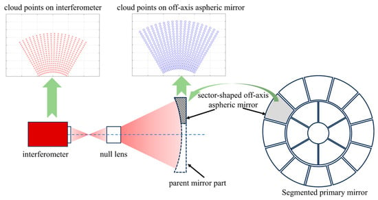
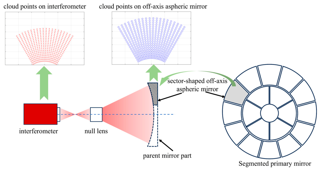
For a large-aperture aspheric primary mirror composed of sector-shaped segments, the optical configuration for testing a sector-shaped sub-mirror using a null lens compensator is schematically illustrated in Figure 1. When the test beam reflected from the mirror surface passes through the null lens and reaches the interferometer detector, the null lens effectively performs an imaging function that relays the test mirror surface onto the detector plane [21]. This imaging process inherently introduces optical distortion, and the resulting image distortion pattern is identical to the mapping distortion present in the interferometric measurement. Consequently, by reversing the test beam path and constructing an equivalent imaging optical path with the test mirror serving as the object, the corresponding imaging distortion can be obtained and analyzed. This principle of optical reciprocity provides a convenient framework for characterizing the mapping distortion of the null lens compensator without requiring a separate calibration setup.
Figure 1.
Schematic diagram of testing sector-shaped off-axis aspheric sub-mirror with null lens.
2.2. Characteristics of Mapping Distortion with Null Lens Compensator
Following the conventional distortion classification framework for imaging lenses, optical distortion can be divided into three primary types: radial distortion, decentering distortion, and thin-prism distortion [30,31,32]. Decentering distortion and thin-prism distortion arise predominantly from misalignments and tilts of optical elements, whereas radial distortion originates mainly from deviations in the curvature of optical surfaces. When the optical components are precisely fabricated and aligned, decentering distortion and thin-prism distortion are generally negligible owing to their minimal magnitude, and radial distortion becomes the dominant residual. Radial distortion conforms to the following equation:
where are the coordinates of the distortion-free points, are the coordinates of the distortion center, is the radial distance from the distortion-free point to the distortion center, are the coordinates of the distorted point corresponding to , and , , …, are the radial distortion coefficients. In practice, retaining the second-order and fourth-order terms (i.e., and ) is generally sufficient to characterize and fit the distortion function, while higher-order terms can usually be neglected without significant loss of accuracy.
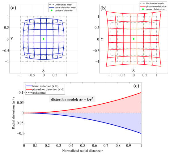
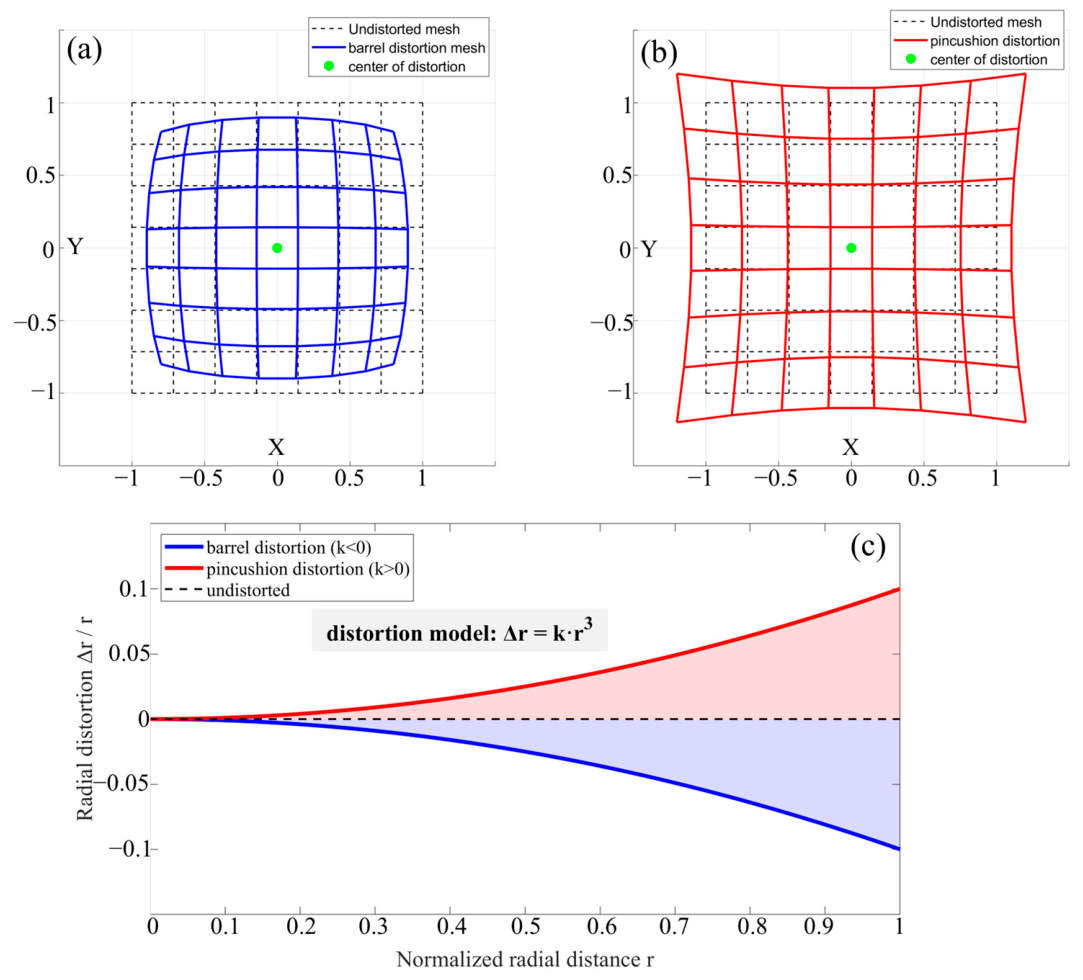
Depending on the sign of the radial distortion coefficients, the mapping distortion causes the distorted image to exhibit different geometric characteristics. For better illustration, a standard distortion-free 7 × 7 grid with a grid spacing of unity is constructed. Let the coordinates of the distortion center be simplified to (0,0). Let the radial distance difference between the distorted point and the distortion-free point be . For the sake of visual clarity and simplicity in this conceptual demonstration, only the second-order term (i.e., ) is considered in the distortion model, but the analysis is equally applicable to distortion models that include higher-order terms. According to Equations (1) and (2), the distorted radial distance and the radial distance difference can be expressed as:
two representative cases are considered by assigning the value of as 0.1 and −0.1, respectively, such that the maximum absolute distortion at the grid edge is 10%. The resulting distorted grid patterns for and are shown in Figure 2a,b, respectively, and the corresponding one-dimensional distorted curves are plotted in Figure 2c. When , the distortion magnitude increases progressively from the center toward the edge, and the distorted grid points contract inward toward the distortion center; the overall pattern assumes a barrel-like shape and is commonly termed barrel distortion. When , the distortion likewise increases from the center to the edge, but the distorted grid points expand outward from the distortion center; the resulting pattern resembles a pincushion and is commonly referred to as pincushion distortion.
Figure 2.
Schematic diagram of radial distortion: (a) barrel distortion (); (b) pincushion distortion (); (c) one-dimensional distorted curves.
2.3. Mapping Distortion of Sector-Shaped Off-Axis Aspheric Surface
A sector-shaped off-axis aspheric surface can be regarded as an off-axis portion extracted from its corresponding rotationally symmetric parent aspheric mirror. Consequently, the mapping distortion inherent in null lens interferometric testing of such a surface follows the same fundamental characteristics as those of the parent aspheric mirror, although its manifestation differs owing to the specific geometry of the sector-shaped segment.
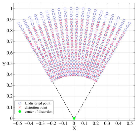
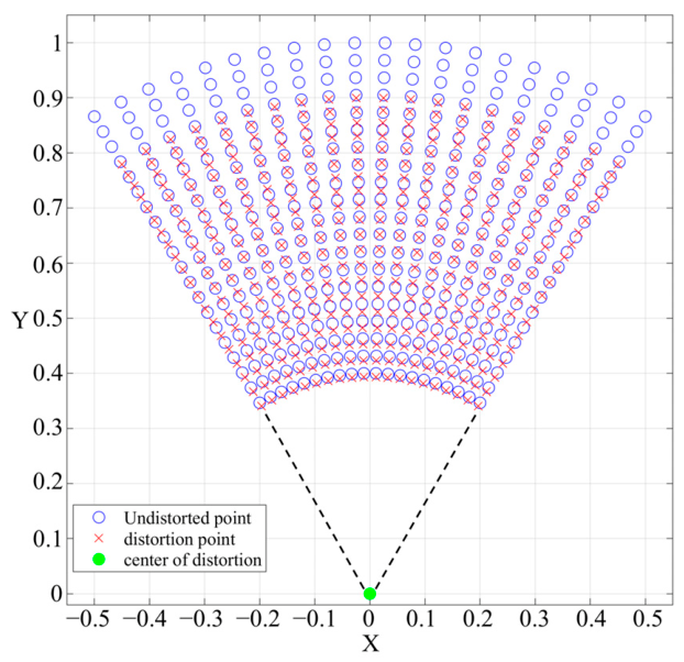
To further illustrate this behavior, a representative sector shape is constructed with a sector angle of 60°, an inner radius of 0.4, and an outer radius of 1. With the radial distortion coefficient set to , the distortion-free points are represented by blue circles, and the corresponding distorted points are indicated by red crosses. The superposition of the distorted points and the distortion-free points is shown in Figure 3. As can be seen from Figure 3, the distorted pattern retains its sector shape overall, and the sector angle remains invariant before and after distortion. This angular invariance makes the distortion in a sector pattern considerably less perceptible on an intuitive level compared with that in a full circular aperture. Nevertheless, owing to the radial distance variation governed by the distortion function, the ratio of the outer radius to the inner radius of the distorted sector pattern decreases compared with that of the undistorted pattern. For the case where the radial distortion coefficient is positive, the opposite effect occurs, i.e., the ratio of the outer radius to the inner radius increases.
Figure 3.
Schematic diagram of mapping distortion of sector-shaped off-axis aspheric surface.
Based on the above characteristics of the distorted pattern obtained in null lens testing of a sector-shaped off-axis aspheric surface, and further supported by our previous work [23], it can be established that the sector-shaped off-axis aspheric surface satisfies three rigorous mathematical properties: (1) the distortion center remains fixed; (2) the straight radial edges of the sector-shaped mirror remain straight, preserving the sector angle; and (3) the nonlinearity of the radial scaling leads to a measurable variation in the outer-to-inner radius ratio. These properties are instrumental for correcting the mapping distortion. Given the known nominal geometric parameters of the sector shape, the coordinates of the distortion center can be determined from the radial boundary data on the distorted pattern. Furthermore, once the radial distortion coefficients are obtained, the mapping distortion can be fully corrected through the inverse coordinate transformation. The detailed mapping distortion correction procedure is presented in Section 3.
3. Mapping Distortion Method
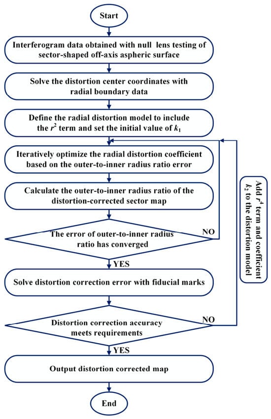
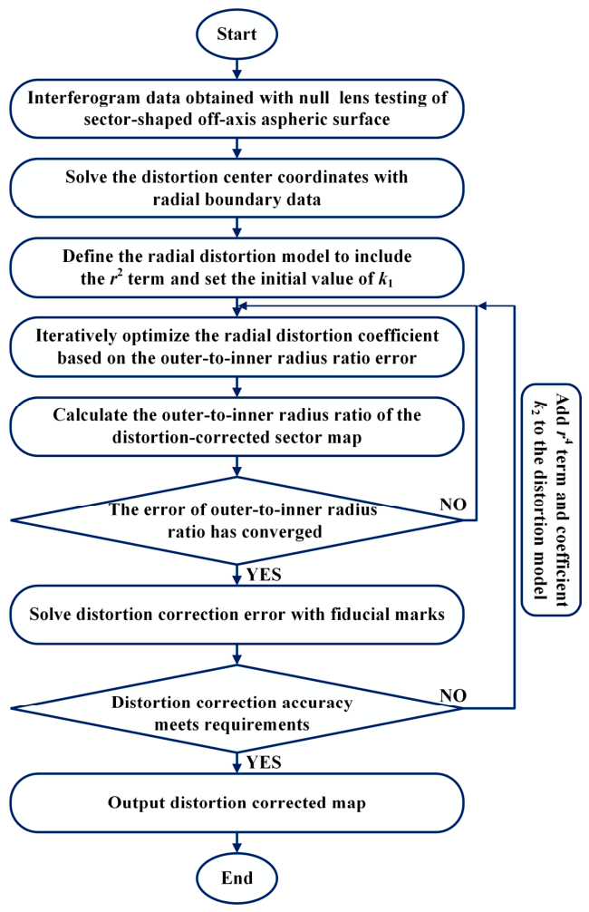
Based on the characteristics and underlying principles of mapping distortion in null lens compensator testing of sector-shaped off-axis aspheric surfaces discussed in Section 2, a novel mapping distortion correction method is proposed. This method comprises two main steps: (1) solving for the distortion center coordinates, (2) determining the radial distortion coefficient and evaluating the residual correction error. The corresponding flowchart is presented in Figure 4. The key steps involved are described in detail in the following subsections.
Figure 4.
Flowchart of mapping distortion correction for sector-shaped off-axis aspheric surfaces.
3.1. Solving for the Distortion Center Coordinates
According to the distortion characteristics of the sector pattern described in Section 2.3, the coordinates of the distortion center are identical in both the distorted and distortion-free configurations, and the overall sector shape is preserved after distortion, with only the ratio of the outer radius to the inner radius being altered. This invariance can be exploited to determine the distortion center directly from the measured distorted pattern.
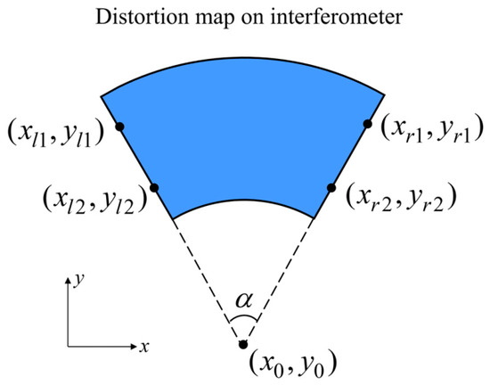
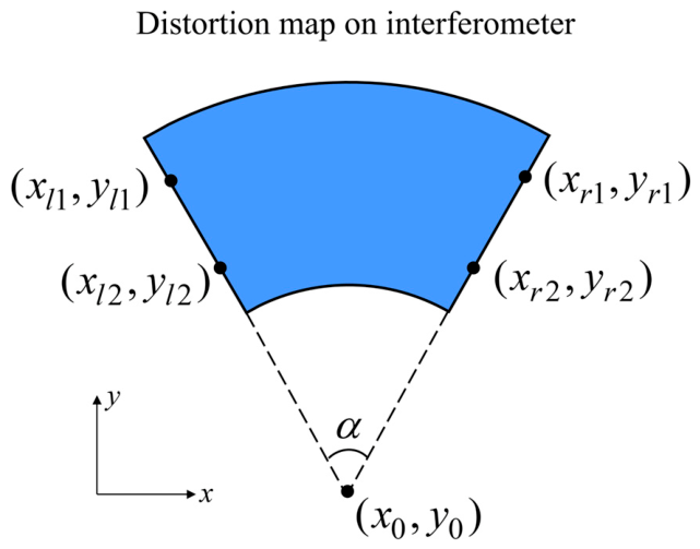
The solution principle is illustrated in Figure 5. Two points are selected on each of the left and right radial boundaries of the distorted sector pattern, denoted as , , , and , respectively. Based on these point coordinates, the equations of the straight lines corresponding to the left and right boundaries can be determined as
where and are the slopes of the left and right boundary lines, and are the corresponding intercepts. These line parameters can be expressed as
Figure 5.
Schematic diagram of solving the distortion center coordinates.
Solving Equations (5) and (6) simultaneously yields the intersection point of the two boundary lines, which corresponds to the distortion center , expressed as
It should be noted that the above calculation of the distortion center coordinates utilizes coordinate points located on the left and right boundaries primarily because these radial boundary points are intuitive and convenient to identify in the measured interferogram. In practice, other pairs of points that are symmetric with respect to the distortion center can also be selected for determining the distortion center coordinates, following the same geometric principle. Furthermore, to improve the accuracy and robustness of the distortion center coordinates solution, the number of selected data point pairs can be increased to more than two, and the optimal distortion center coordinates can be obtained by a least-squares fit with multiple pairs of data.
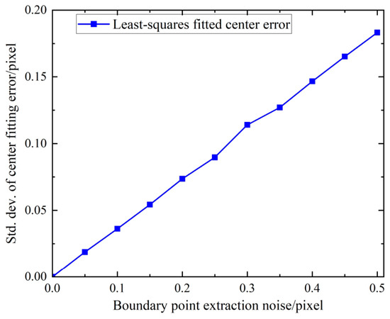
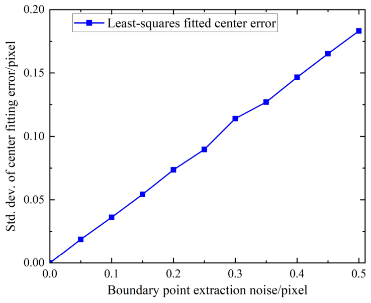
Notably, the accuracy of the distortion center coordinates directly affects the subsequent correction. The main error source in this step is the pixel-level quantization error during the radial boundary extraction. To systematically quantify this error propagation, we have performed a numerical simulation. In the simulation, we set the outer radius to 400 pixels, the inner radius to 160 pixels (inner-to-outer radius ratio of 0.4), and adopted a first-order radial distortion coefficient , resulting in a maximum distortion of approximately 64 pixels at the outer edge. Based on the established theory of sub-pixel edge extraction, we selected 0.5 pixels as the upper bound for the boundary noise. Accordingly, random noise ranging from 0.1 to 0.5 pixels was added to the boundary data.
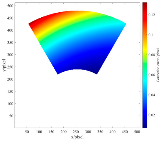
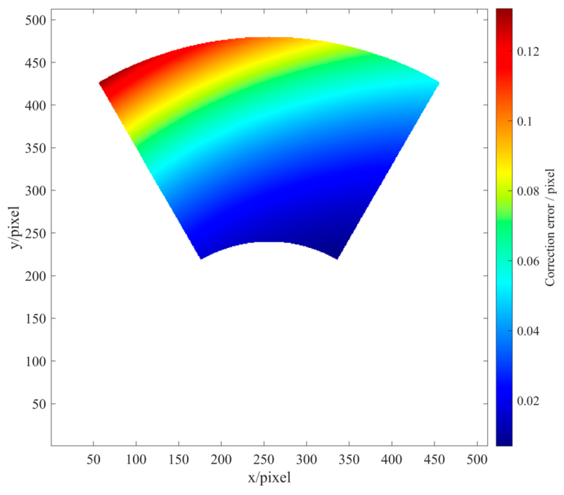
As shown in Figure 6, the standard deviation of the fitted distortion center from the true value remains consistently below 0.2 pixels even under the worst-case boundary extraction error of 0.5 pixels, demonstrating high stability of the least-squares fitting method. Furthermore, we evaluated the impact of this center fitting error on the final distortion correction. By setting the deviations of pixels and pixels each, as illustrated in Figure 7, the maximum correction error caused by the center point deviation is only about 0.13 pixels, and the RMS of the distortion correction error is 0.059 pixels. Consequently, this boundary extraction error is negligible and has a marginal influence on the final correction accuracy, which will not impair the high-precision deterministic figuring.
Figure 6.
Distortion center fitting error as a function of the boundary point extraction error using the Monte Carlo method.
Figure 7.
Impact of the distortion center coordinate error on distortion correction ( pixels, pixels).
3.2. Determination of Radial Distortion Coefficients and Correction Error Evaluation
Once the coordinates of the distortion center are determined, the radial distortion coefficients must also be obtained to accomplish full mapping distortion correction through inverse coordinate transformation. Inaccurate radial distortion coefficients will alter the outer-to-inner radius ratio of the distortion-corrected sector pattern, leading to under- or over-correction.
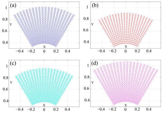
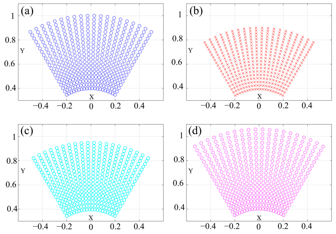
To illustrate this effect quantitatively, simulations were performed based on the same sector geometry used in Figure 3 (sector angle 60°, inner radius of 0.4, outer radius of 1, corresponding to a nominal outer-to-inner radius ratio of 2.5). Using the same distortion model as in Figure 3, applying the inverse solution with the perfect correction coefficient would yield an ideal mapping distortion correction. However, when the coefficient employed in this inverse solution deviates from the perfect value, the mapping distortion correction results exhibit corresponding errors. With deviations of +0.05 and −0.05 from the perfect value (corresponding to inverse coefficients and , respectively), the corrected patterns obtained via the inverse function are shown in Figure 8c,d, respectively. For reference, the original distortion-free pattern and the distorted pattern are displayed in Figure 8a,b. When , the resulting outer-to-inner radius ratio of the corrected sector is approximately 2.3878, which is smaller than the nominal value, indicating an under-corrected state. When , the outer-to-inner radius ratio of the corrected sector is approximately 2.6254, exceeding the nominal value, corresponding to an over-corrected state.
Figure 8.
Influence of radial distortion coefficient error on the mapping correction: (a) distortion-free pattern; (b) distorted pattern (); (c) under-correction pattern ( used for correction); (d) over-correction pattern ( used for correction).
Based on the above analysis, the deviation of the outer-to-inner radius ratio of the corrected image from its theoretical value is adopted as the primary distortion correction error metric. An iterative optimization algorithm is employed to adjust the radial distortion coefficients to minimize this ratio error. Once the error falls below a predetermined threshold, the radial distortion coefficients are preliminarily determined.
However, relying solely on the radius ratio error may be insufficient when higher correction precision is required, as it only constrains the global scaling of the sector pattern. To further refine the solution and to assess the actual correction accuracy, a fine error evaluation step is introduced with few fiducial marks on the surface under test. After the radius ratio error has converged, the residual deviation between the known coordinates of fiducial marks on the mirror surface and their corresponding distortion-corrected coordinates is computed. This deviation serves as the refined correction error, defined as
where are the coordinates of the i-th fiducial mark, are the distortion-corrected coordinates corresponding to the marked points, and is the distortion correction error.
If the second-order radial distortion model yields a residual error that exceeds the required accuracy, a fourth-order term can be further introduced into the distortion model. The iterative optimization is then repeated, using the same combined error evaluation consisting of the radius ratio deviation and the fiducial mark residuals, until satisfies the convergence criterion. In this way, the determination of the radial distortion coefficients and the quantitative evaluation of the correction accuracy are tightly coupled, ensuring that the obtained coefficients can fully meet the precision demand of deterministic figuring.
4. Results
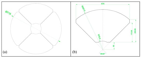
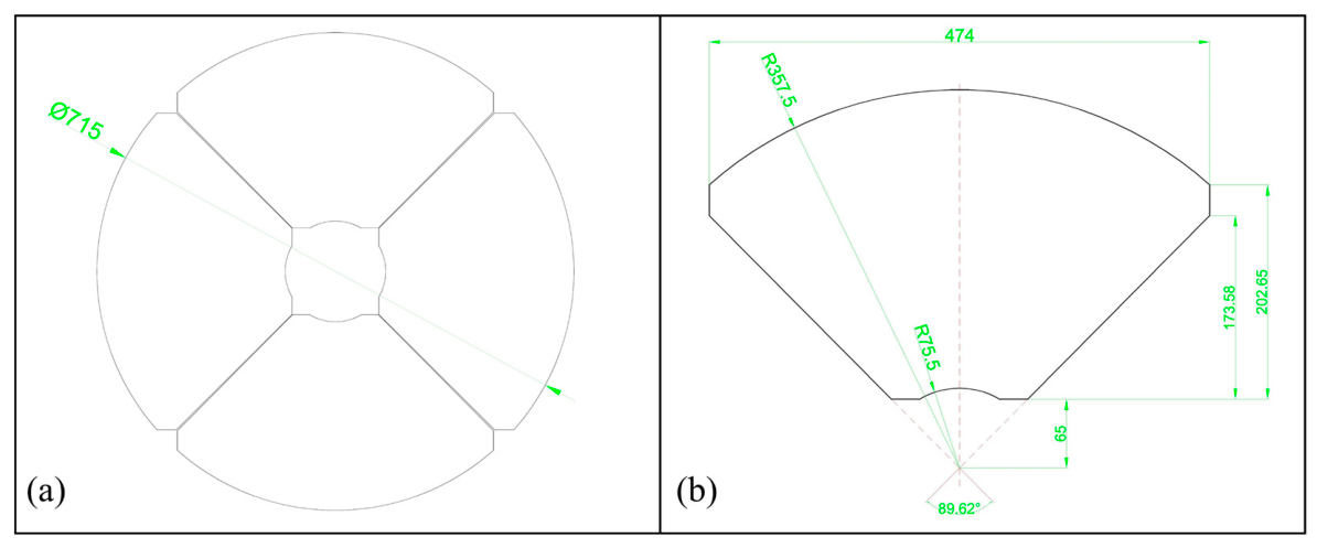
To meet the practical requirements of a segmented telescope with a primary mirror diameter of 715 mm, the primary mirror consists of four sector-shaped sub-mirrors, and the segmented primary mirror assembly is shown in Figure 9a. The mapping distortion correction method proposed in this paper was experimentally validated on a sector-shaped off-axis aspheric sub-mirror. The test mirror is characterized by a paraxial radius of curvature of −2538 mm, a conic constant K = −0.910757, an inner radius of 75.5 mm, an outer radius of 357.5 mm, and a corresponding sector angle of 89.62°. The geometric shape of the off-axis aspheric surface is shown in Figure 9b, where the edge chamfers are introduced for safety and mirror mounting requirements.
Figure 9.
(a) Segmented primary mirror assembly consisting of four sector-shaped sub-mirrors. (b) Geometric shape of the tested sector-shaped off-axis aspheric sub-mirror.
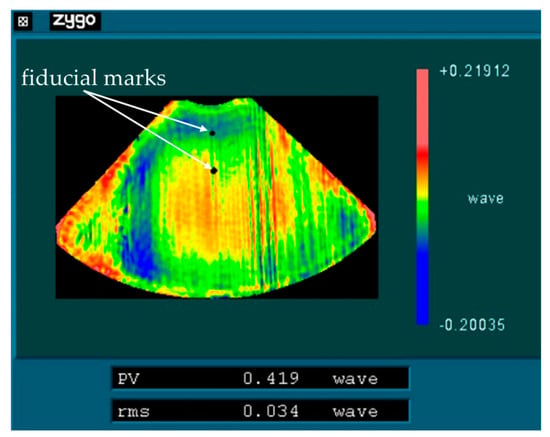
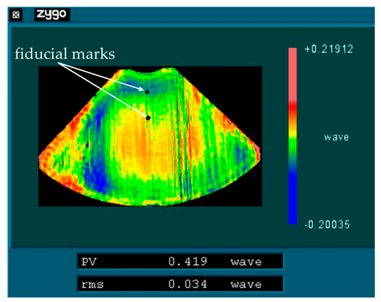
The interferometric test result of the sector-shaped off-axis aspheric mirror obtained with the null lens compensator is presented in Figure 10. Two fiducial marks were placed on the mirror surface to support the subsequent mapping distortion correction. Based on the nominal geometric parameters of the sector-shaped mirror, the theoretical outer-to-inner radius ratio is approximately 4.7351. In contrast, the ratio measured from the interferogram is approximately 5.1184, yielding a ratio error of 0.3833. This radius ratio deviation translates to a maximum radial distortion of approximately 28.9 mm at the outer edge, corresponding to a relative distortion of 8.1% of the outer radius. This clearly indicates the presence of significant mapping distortion in the interferogram; therefore, mapping distortion correction is essential for deterministic figuring.
Figure 10.
Interferogram of the sector-shaped off-axis aspheric surface under test.
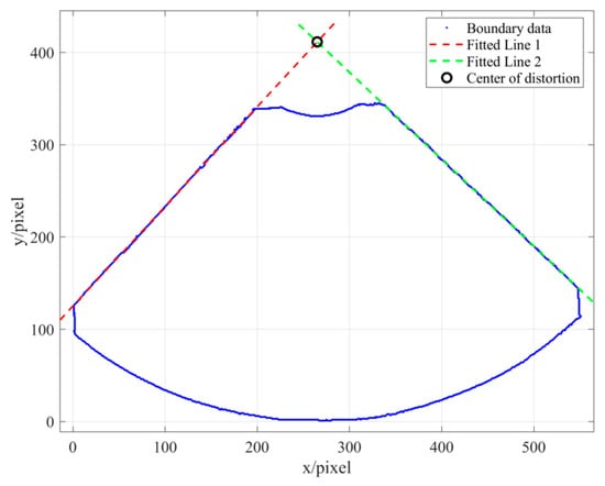
Firstly, the distortion center coordinates are solved using the boundary data of the interferogram, as shown in Figure 11. The procedure for solving the distortion center coordinates is as follows: First, the boundary data points of the distorted sector interferogram were extracted, as indicated by the blue points in Figure 11. Then, the data points on the two radial boundaries were used to fit two straight lines, shown as the red dashed line and the green dashed line in Figure 11, with the fitted coefficients , and , , respectively. Finally, the intersection point of these two fitted lines was calculated to determine the distortion center coordinates, as indicated by the black circle in the figure. The solved distortion center coordinates are pixels, pixels.
Figure 11.
Distortion center coordinates solved using the boundary data of the interferogram.
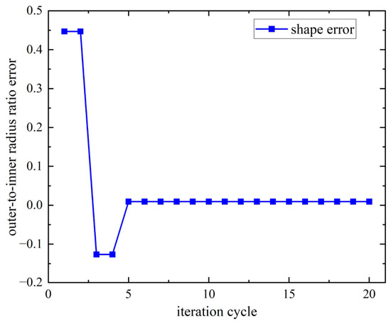
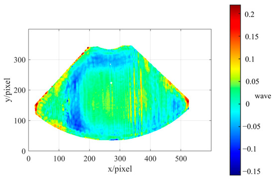
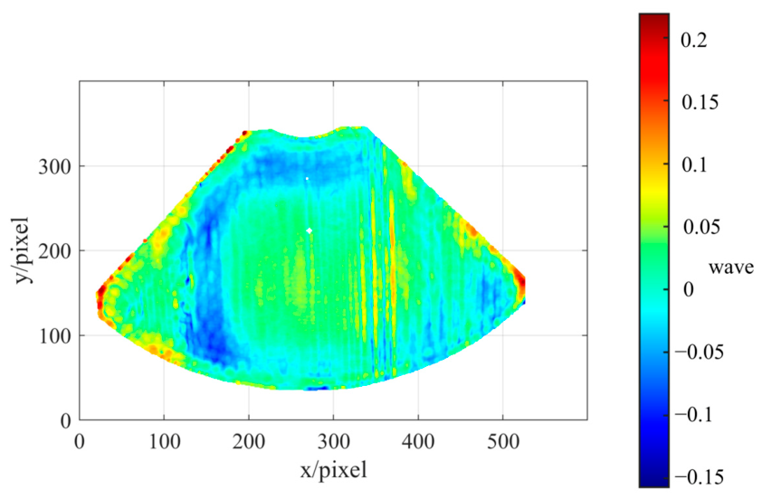
Secondly, the second-order radial distortion coefficient is solved based on the outer-to-inner radius ratio. The optimal is determined iteratively using the bisection method, with the lower and upper bounds initially set to 0 and 0.5, respectively. The variation in the outer-to-inner radius ratio with the number of iterations is shown in Figure 12. The ratio converges rapidly, dropping from the original 0.3833 to 0.0094 after 5 iterations. Furthermore, to improve the correction accuracy, the fourth-order radial distortion coefficient is incorporated, and the two fiducial marks are used to achieve a more accurate solution of the second-order and fourth-order coefficients. After correction, the maximum deviation between the actual coordinates of the two fiducial marks and their corresponding distortion-corrected coordinates is approximately 0.91 mm. The distortion-corrected map is shown in Figure 13.
Figure 12.
Convergence of the outer-to-inner radius ratio with the number of iterations.
Figure 13.
Distortion-corrected map.
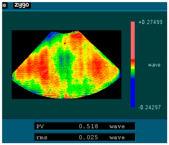
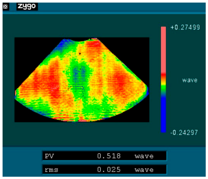
To validate the effectiveness of the distortion correction, deterministic figuring was performed based on the distortion-corrected interferogram. Figure 14 shows the interferogram measured after a single figuring run. The surface figure error RMS converged from 0.034λ to 0.025λ (λ = 632.8 nm), demonstrating both the correctness of the distortion correction and its practical value in guiding high-precision deterministic figuring. Notably, the same correction strategy was applied to the other three sector-shaped sub-mirrors, whose final surface figures are provided in the Supplementary Material. The resulting RMS values for the four sub-mirrors were 0.025λ, 0.027λ, 0.028λ, and 0.024λ, with a mean of 0.026λ and a standard deviation of 0.0018λ. This statistical consistency strongly attests to the high repeatability of the proposed method within the same batch.
Figure 14.
Interferogram after a single figuring run based on the distortion correction result.
5. Discussion
In this paper, we propose a mapping distortion correction method for sector-shaped off-axis aspheric surfaces tested with a null lens compensator. Compared with traditional approaches, our method achieves distortion correction without requiring detailed parameters of the null lens and relies on only a few sparse fiducial marks for validation. For segmented telescopes composed of sector-shaped sub-mirrors, the sub-mirrors located in the same concentric annular ring share identical geometric parameters. Consequently, once the radial distortion coefficients are determined based on the test data of one sub-mirror, they can be directly applied to support the testing of other sub-mirrors within the same ring. This characteristic greatly facilitates rapid batch manufacturing and testing of segmented sub-mirrors.
In terms of mapping distortion correction accuracy, the proposed method achieves a precision comparable to that of related studies in this field. Reference [26] proposed a ray-tracing and fiducial-calibration hybrid method for freeform mirror testing, reporting a maximum synthetic position error of 0.783 mm (see Table 1 in Ref. [26]) for two mirrors fixed on a 790 mm × 390 mm SiC substrate. In this work, the residual error of our method is 0.91 mm for a sector-shaped mirror with an aperture of approximately 357 mm. Although the absolute error of our method is slightly larger, it remains within the sub-millimeter to millimeter range, which is sufficiently small compared with the tool influence function used in deterministic figuring. Therefore, our correction precision is well within the practical tolerance band achievable by high-precision methods in the literature and fully satisfies the requirements of deterministic manufacturing.
In terms of practical convergence efficiency during deterministic figuring, the proposed method demonstrates good performance. The most rigorous test for whether the distortion map meets the requirement is the actual convergence behavior in the deterministic figuring process. Reference [27] employed 37 fiducial marks and orthogonal vector polynomials to correct the mapping distortion of a 1000 mm off-axis parabolic mirror. The surface RMS converged from 0.034λ to 0.0198λ (λ = 632.8 nm) over 10 figuring cycles (see Table 1 in Ref. [27]), corresponding to an average convergence rate of 0.00142λ per run. In contrast, our experimental validation shows that the surface RMS decreased from 0.034λ to 0.025λ after just a single figuring run, yielding a convergence rate of 0.009λ per run. Given that the mirror in Reference [27] has a 1000 mm aperture while ours is approximately 357 mm, it is recognized that a smaller mirror generally allows for faster convergence. However, even considering this size advantage, the achieved convergence rate of 0.009λ per run in our experiment remains remarkably efficient. Furthermore, this level of convergence efficiency is fully consistent with the typical performance observed in our previous work [23], which strongly corroborates that the corrected distortion map provides sufficient accuracy for guiding high-precision deterministic figuring.
Nevertheless, several practical considerations and potential extensions are worth noting:
(1) Selection of fiducial mark spacing
When only two fiducial marks are employed, taking measurement errors into account, an excessively short spacing between the two markers may render the solution of the coefficient matrix ill-conditioned. Increasing the radial spacing between the two markers enhances the robustness of the coefficient solution and improves distortion correction accuracy.
Regarding the selection of fiducial marks, it is important to emphasize that the global distortion coefficients are primarily constrained by the outer-to-inner radius ratio, which incorporates the extreme radial boundaries. Therefore, the fiducial marks are not required to be placed exactly at the physical edges for coefficient fitting. Instead, their role is to provide an independent validation of the correction accuracy across the effective aperture. To ensure the validation is robust and global, the two marks should be placed with maximum radial span, ideally one near the inner working zone and the other near the outer working zone, while edge diffraction regions are avoided. This arrangement separates the optimization data based on the radius ratio from the validation data provided by the fiducial marks, which eliminates data redundancy and helps ensure the entire surface figure is correctly corrected.
(2) Mapping distortion correction accuracy improvement
In the current setup, we deliberately used only two fiducial marks to maintain operational simplicity and high testing efficiency. To further enhance the distortion correction accuracy in future work, the following approaches can be considered:
(a) Optimizing the radial spacing: The current radial span of the two fiducial marks is limited. By placing one mark near the inner effective edge and the other near the outer effective edge, the condition number of the inverse correction matrix becomes well-conditioned, thereby making the coordinate mapping much more robust against local boundary extraction errors.
(b) Modestly increasing the number of markers: Without significantly compromising the testing efficiency, adding a small number of extra markers would allow a more stringent cross-validation of the solved distortion coefficients, further reducing the mapping residual.
(c) Global parameter optimization: Currently, the distortion center coordinates and radial distortion coefficients are solved via a stepwise iterative calculation. In the future, adopting a global optimization algorithm to jointly solve for the optimal parameter set would help further improve the distortion correction accuracy.
(3) Limitations and future extensions
It should be noted that the current method is specifically optimized for the one-dimensional radial distortion introduced by the rotationally symmetric null lens for sector-shaped off-axis aspheres. Although the algorithm is validated using sector-shaped segments in this work, its core principle, relying on the inherent radial symmetry of the null lens distortion, allows it to be readily adapted to other off-axis aspheric geometries. By applying appropriate geometric adjustments to the boundary constraints, such as defining the length-to-width ratio for rectangular mirrors or the radial distance ratio between the inner and outer edges for hexagonal or annular segments, the method can be extended to various segment shapes without altering its fundamental workflow. A recognized limitation, however, is its applicability to more complex freeform surfaces, where the mapping distortion becomes non-rotationally symmetric and requires two-dimensional vector-polynomial fitting. Additionally, while our method has been successfully applied to guide the deterministic figuring of four identical sector-shaped mirrors in our batch manufacturing, further increasing the number of samples or optimizing the marker placement strategy in the mid-radial region could provide even stronger statistical validation. Future work will focus on extending this methodology to general freeform surfaces and integrating global optimization algorithms to achieve higher system-level automation and correction performance.
6. Conclusions
In null lens testing of sector-shaped off-axis aspheric sub-mirrors, mapping distortion prevents the measured interferogram from directly guiding deterministic figuring. This paper proposes a mapping correction method that exploits the one-dimensional radial symmetry of the null lens distortion. The distortion center is determined from the radial boundary data of the distorted sector interferogram, and the radial distortion coefficients are iteratively solved by minimizing the outer-to-inner radius ratio error in combination with a sparse set of fiducial marks. Finally, an inverse coordinate transformation is performed with the determined center and coefficients to correct the mapping distortion. Experimental validation on a sector-shaped mirror reduced the radius ratio error from 0.3833 to 0.0094, with a maximum fiducial coordinate deviation of 0.91 mm. Based on the corrected map, a single figuring run reduced the surface figure RMS from 0.034λ to 0.025λ (λ = 632.8 nm). Furthermore, the proposed method was also applied to guide the deterministic figuring of another three sector-shaped sub-mirrors of the segmented primary mirror, yielding final surface figure errors of 0.027λ, 0.028λ, and 0.024λ, respectively, with a mean of 0.026λ and a standard deviation of 0.0018λ. This statistical consistency strongly attests to the high repeatability of the proposed method within the same batch. Compared with existing approaches, the proposed method eliminates the need for complete compensator parameters and computationally intensive ray tracing, and substantially reduces the number of fiducial marks, making it particularly well suited for the batch manufacturing of sector-shaped segments in large segmented optical telescopes. Furthermore, the proposed method is not only applicable to sector-shaped off-axis aspheric mirrors, but also, after an adaptive modification of the shape error evaluation metric, can be extended to mapping distortion correction in null lens testing of off-axis aspheres of other shapes.
Supplementary Materials
The following supporting information can be downloaded at: https://www.mdpi.com/article/10.3390/photonics13080712/s1, Figure S1: Final surface figure of Sub-mirror 1; Figure S2: Final surface figure of Sub-mirror 2; Figure S3: Final surface figure of Sub-mirror 3.
Author Contributions
Conceptualization, S.H., X.L. and X.G.; methodology, S.H. and D.Z.; software, Y.Z. and S.L.; validation, S.H., D.Z. and Y.Z.; formal analysis, S.H. and D.Z.; investigation, S.H. and S.L.; resources, X.L. and X.G.; data curation, S.H.; writing—original draft preparation, S.H. and D.Z.; writing—review and editing, S.H., X.L. and X.G.; visualization, D.Z. and Y.Z.; supervision, X.L. and X.G.; project administration, S.H. and X.L.; funding acquisition, X.L. and X.G. All authors have read and agreed to the published version of the manuscript.
Funding
This research was funded by The Science and Technology Application Promotion Fund (145XXX050532000X) and The Independent Research Fund for Science and Technology Innovation Talents (HZ2025968QN18).
Data Availability Statement
Data supporting the findings of this study are available from the corresponding author upon reasonable request.
Conflicts of Interest
The authors declare no conflicts of interest.
References
- Zhang, Z.; Chen, J.; You, S.; Ma, W.; Wu, H.; Chang, C.; Zhang, Y.; You, Z.; Liang, Y.; Li, D.; et al. A review of manufacturing technology progress for astronomical telescope mirrors—From material innovation to Full-Spatial-Frequency error control. Light Adv. Manuf. 2026, 7, 128–158. [Google Scholar]
- Kim, D.; Choi, H.; Brendel, T.; Quach, H.; Esparza, M.; Kang, H.; Feng, Y.; Ashcraft, J.N.; Ke, X.; Wang, T. Advances in optical engineering for future telescopes. Opto-Electron. Adv. 2021, 4, 210040. [Google Scholar] [CrossRef] [Scilit]
- Cheng, J. Fundamentals of Optical Telescopes. In The Principles of Astronomical Telescope Design; Burton, W.B., Ed.; Springer: New York, NY, USA, 2009; Volume 1, pp. 1–86. [Google Scholar]
- Dong, D.; Pang, X.; Zhang, X.; Fan, Y.; Li, Z.; Yang, L.; Hu, H. Key technology in developing of metrology mount for large aperture monolithic space-based mirror. Opt. Precis. Eng. 2019, 27, 2166–2179. [Google Scholar] [CrossRef] [Scilit]
- Thorsten, D. The market of huge monolithic mirror substrates for optical astronomy. In Proceedings of the Material Technologies and Applications to Optics, Structures, Components, and Sub-Systems, San Diego, CA, USA, 30 September 2013. [Google Scholar]
- Martin, H.M.; Ceragioli, R.; Gasho, V.; Jannuzi, B.T.; Kim, D.W.; Kingsley, J.S.; Law, K.; Loeff, A.; Lutz, R.D.; Meyen, S.; et al. Production of 8.4 m primary mirror segments for GMT. In Proceedings of the Advances in Optical and Mechanical Technologies for Telescopes and Instrumentation V, Montreal, QC, Canada, 20 September 2022. [Google Scholar]
- Martin, H.; Allen, R.; Burge, J.; Kim, D.W.; Kingsley, J.; Tuell, M.; West, S.; Zhao, C.; Zobrist, T. Fabrication and testing of the first 8.4-m off-axis segment for the Giant Magellan Telescope. In Proceedings of the Modern Technologies in Space-and Ground-Based Telescopes and Instrumentation, San Diego, CA, USA, 19 July 2010. [Google Scholar]
- Zheng, Y.; Tang, L.; Liang, B.; Li, Y. Primary mirror segmentation for large optical telescopes: An inversemap projection approach. Appl. Opt. 2021, 60, 6015–6022. [Google Scholar] [PubMed]
- Rao, C.H.; Zhong, L.B.; Guo, Y.M.; Li, M.; Zhang, L.Q.; Wei, K. Astronomical adaptive optics: A review. PhotoniX 2024, 5, 16. [Google Scholar] [CrossRef] [Scilit]
- Skidmore, W. The Thirty Meter Telescope 2024 Detailed Science Case-The Update Process and Science Highlights. In Proceedings of the American Astronomical Society Meeting Abstracts, National Harbor, MD, USA, 14 January 2025. [Google Scholar]
- Padovani, P.; Cirasuolo, M. The Extremely Large Telescope. Contemp. Phys. 2023, 64, 47–64. [Google Scholar] [CrossRef] [Scilit]
- Hakobyan, A.V. Aperture shapes and the effectiveness of ground-based large and extremely large telescopes. Mon. Not. R. Astron. Soc. 2020, 496, 5414–5422. [Google Scholar] [CrossRef] [Scilit]
- Shen, S.; Cui, X.; Zhang, Y. Simulation and Analysis of Co-phasing Errors of the Segmented Primary Mirror Tiled by Petal-shaped Segments in LOT. Acta Astron. Sin. 2022, 63, 6. [Google Scholar]
- Shen, S.; Cui, X.; Zhang, Y. Simulation and analysis of co-phasing errors of the segmented primary mirror tiled by hexagonal segments in LOT. Res. Astron. Astrophys. 2021, 21, 245–254. [Google Scholar] [CrossRef] [Scilit]
- Hu, H.; Zhang, X.; Ford, V.; Luo, X.; Qi, E.; Zeng, X.; Zhang, X. Edge control in a computer controlled optical surfacing process using a heterocercal tool influence function. Opt. Express 2016, 24, 26809–26824. [Google Scholar] [CrossRef] [Scilit] [PubMed]
- Wei, Y.; Cheng, R.; Li, L.; Cheng, Q.; Pan, Y.; Zhu, C.; Zhang, J.; Zheng, J.; Ai, B. Precision Calibration of Robot Magnetorheological Finishing System Based on Laser Tracker. Photonics 2025, 12, 57. [Google Scholar] [CrossRef] [Scilit]
- Pradhan, P.; Shurvinton, R.; Bourgenot, C.; Wang, H.; Sawhney, K. Ultra-high precision NiP mirror fabrication using ion beam figuring for space applications. Opt. Express 2025, 33, 17721–17734. [Google Scholar] [CrossRef] [Scilit] [PubMed]
- Wang, S.; Kong, L.; Lü, H. Advances in measurement and error evaluation technique of optical freeform surfaces. Acta Opt. Sin. 2023, 43, 243–262. [Google Scholar]
- Li, S.; Zhang, J.; Liu, W.; Liang, H.; Xie, Y.; Li, X. The Methods and Experiments of Shape Measurement for Off-Axis Conic Aspheric Surface. Materials 2020, 13, 2101. [Google Scholar] [CrossRef] [Scilit] [PubMed]
- Wang, X.; Li, X.; Zhang, Q.; Wei, W.; Liu, E. Efficient Testing Light Path for Aspherical Surfaces Based on Secondary Imaging. Photonics 2025, 12, 485. [Google Scholar] [CrossRef] [Scilit]
- Novak, M.; Zhao, C.; Burge, J. Distortion mapping correction in aspheric null testing. In Proceedings of the Interferometry XIV: Techniques and Analysis, San Diego, CA, USA, 11 August 2008. [Google Scholar]
- Robinson, B.M.; Reardon, P.J. Distortion compensation in interferometric testing of mirrors. Appl. Opt. 2009, 48, 560–565. [Google Scholar] [CrossRef] [Scilit] [PubMed]
- Hao, S.; Zhang, J.; Yang, J.; An, F. Mapping distortion correction in off-axis aspheric mirror testing with a null compensator. Appl. Opt. 2022, 61, 4040–4046. [Google Scholar] [CrossRef] [Scilit] [PubMed]
- Xu, H.; Liu, J.; Chen, S. Research on Nanometer Precision Measurement Method of High Order Even Aspheres. Appl. Sci. 2024, 14, 9969. [Google Scholar] [CrossRef] [Scilit]
- Chen, S.; Hu, H.; Guan, C. Fiducial free correction of mapping distortion in null test of aspheres and freeforms. Opt. Commun. 2022, 506, 127560. [Google Scholar] [CrossRef] [Scilit]
- Zeng, X.; Zhang, X.; Xue, D.; Zhang, Z.; Jiao, J. Mapping distortion correction in freeform mirror testing by computer-generated hologram. Appl. Opt. 2018, 57, F56–F61. [Google Scholar] [CrossRef] [Scilit] [PubMed]
- E, K.; Zhao, J.-K.; Wang, B.; Wang, D.; Shen, Y.; Fu, X.; Xu, S.; Li, J.; Xue, X.; Chang, M.; et al. Distortion mapping correction in AIMS primary mirror testing by computer-generated hologram. Res. Astron. Astrophys. 2021, 21, 165. [Google Scholar] [CrossRef] [Scilit]
- Zhou, P.; Martin, H.M.; Zhao, C.; Burge, J.H. Mapping Distortion Correction for GMT Interferometric Test. In Proceedings of the Imaging and Applied Optics Technical Papers, Monterey, CA, USA, 24 June 2012. [Google Scholar]
- Zhao, C.; James, H.B. Orthonormal vector polynomials in a unit circle, application: Fitting mapping distortions in a null test. In Proceedings of the Optical Manufacturing and Testing VIII, San Diego, CA, USA, 21 August 2009; pp. 253–260. [Google Scholar]
- Wang, J.; Shi, F.; Zhang, J.; Liu, Y. A new calibration model of camera lens distortion. Pattern Recognit. 2008, 41, 607–615. [Google Scholar] [CrossRef] [Scilit]
- Ikokou, G.B.; Shoko, M.; Tagoe, N.D. Inverse Analytical Formula for the Correction of Severe Barrel Lens Distortion Modelled by a Depressed Radial Distortion Polynomial. Sensors 2026, 26, 1896. [Google Scholar] [CrossRef] [Scilit] [PubMed]
- Peng, H.; Sun, C.; Wang, P. The Design and Implementation of the Lookup Table in Distortion Correction for the Optical System. IEEE Access 2023, 11, 44335–44342. [Google Scholar] [CrossRef] [Scilit]
Disclaimer/Publisher’s Note: The statements, opinions and data contained in all publications are solely those of the individual author(s) and contributor(s) and not of MDPI and/or the editor(s). MDPI and/or the editor(s) disclaim responsibility for any injury to people or property resulting from any ideas, methods, instructions or products referred to in the content. |
© 2026 by the authors. Licensee MDPI, Basel, Switzerland. This article is an open access article distributed under the terms and conditions of the Creative Commons Attribution (CC BY) license.