


Abstract
Sapphire, with excellent optical properties and high hardness, has become a key hard and brittle material component in extreme environments like aviation equipment and infrared detection systems. Its processing quality directly determines the performance of various equipment systems. To address processing defects, technologies such as multi-wire cutting, magnetorheological polishing, chemical mechanical polishing, femtosecond laser processing, and ion beam etching have been developed and studied to improve the surface quality of sapphire components. This paper focuses on key technologies, including sapphire’s nano-scale surface morphology control, intrinsic nano-surface atomic-level defect control, and combined process systems for precision and shape control. These technologies lay the foundation for sapphire components’ process chain manufacturing to achieve high-precision shape and surface quality control.
1. Introduction
Sapphire crystal is the core supporting material for optoelectronic systems in extreme environments. It has excellent optical properties (covering high transmittance from ultraviolet to mid-infrared bands) [1], extremely high hardness (Mohs hardness 8.5, second only to diamond) [2], excellent high temperature resistance (melting point of 2050 °C), and chemical stability [3]. Sapphire plays an irreplaceable role as a key optical window component in the optical fairing of hypersonic missiles [4], shipboard and spaceborne infrared warning systems [5], as well as advanced targeting pods and photoelectric countermeasure equipment in the defense field [6]. The precise control of its nano-scale surface morphology and intrinsic performance directly determines the core indicators such as infrared detection sensitivity and laser energy transmission efficiency. Therefore, sapphire nano-precision shape-controlled manufacturing technology has become a key bottleneck to promote the performance breakthrough of high-end photoelectric systems.
The manufacturing process of sapphire components currently needs to break through three core bottlenecks. One of the challenges is due to its typical hard and brittle material properties: highly oriented lattice structure and strong molecular bonding force, which can easily induce subsurface microcracks (up to 15 microns in depth under traditional methods) and surface scratches [5,7,8,9]. Secondly, the spectral characteristics formed during the processing, including low-frequency surface shape deviation, medium-frequency waviness, and high-frequency surface finish, have significant coupling effects [10]. It is difficult for a single processing technology to simultaneously achieve the dual control objectives of nano-scale surface shape accuracy (PV value needs to be less than 50 nm) and atomic roughness (Ra value is less than 0.1 nm) [7]. Thirdly, its adaptability under extreme conditions is obviously insufficient: residual grinding medium and chemical pollutants reduce the laser damage threshold [11], and the mechanism of performance degradation in high-temperature and high-pressure environments remains unclear [12].
The above problems have been systematically studied by scholars at home and abroad and achieved phased breakthroughs. First, on the surface shape control, multi-wire cutting technology achieves efficient fragmentation of sapphire wafers [13] and magnetorheological polishing can converge low-frequency surface shape error from 200 nm to 25 nm [7]. Chemical mechanical polishing (CMP) combined with dielectrophoresis effect improves the material removal rate by 27.3% [14]. Secondly, in terms of surface controllability, femtosecond laser combined with chemical etching can prepare nano-scale microstructures [6], and ion beam cleaning technology can completely remove surface contaminated particles and increase surface free energy [15]. Thirdly, in the composite process, ultrasonic vibration assisted CMP [16] and cluster magnetorheological polishing [17] achieve ‘high efficiency-high quality’ balance, with the minimum surface roughness reaching 0.083 nm [18].
2. Nano-Precision Surface Shape Control Manufacturing Technology
With the increasing demand for high efficiency of energy transmission and irradiation distance in laser systems, laser systems have high requirements for the quality of optical components. Nano-precision surface shape control manufacturing requires the error of shape control manufacturing to converge to the nanometer level. Therefore, a variety of technologies have emerged to help realize the shape-control manufacturing technology in nano-precision.
2.1. Sapphire Multi-Wire Cutting Process
Sapphire is a hard and brittle material. As a hard and brittle material, sapphire is difficult to cut due to its highly oriented internal crystal structure and strong intermolecular bonding force. Traditional inner and outer circle cutting methods are ineffective for it, and the emergence of multi-wire cutting technology—especially high-speed diamond wire cutting equipment—has gradually expanded its processing applications [13]. Because its internal crystal structure has the same direction, the binding force between its molecules is large, and it is difficult to cut. Some traditional inner circle and outer circle cutting methods may not be able to effectively cut sapphire. With the emergence of multi-wire cutting technology, the development and application of high-speed diamond wire cutting equipment has gradually expanded. The swing high-speed multi-wire cutting machine independently developed by Chen Yu’s team [13] explored and studied the sapphire cutting process.
2.2. Low-Frequency Surface Shape Error-Ultra-Precision Cutting, Magnetorheological
2.2.1. Ultrasonic Vibration-Assisted Ultra-Precision Grinding
In order to solve the problem that the subsurface damage is not easy to control during the surface machining of sapphire, Zhang Yunqiang and his team [5] successfully developed a nano-abrasive, fixed-abrasive grinding wheel (its particle size is less than 5 μm). The team combined their new grinding wheel with ultrasonic vibration grinding technology (frequency is set to 20 kHz, amplitude is 5 μm) to assist the combination, so that the subsurface crack depth is greatly reduced compared with the traditional grinding method, and the original 15 μm is reduced to less than 3 μm.
2.2.2. Magnetorheological Polishing
The principle of magnetorheological polishing technology is to adjust the shear stress of the polishing fluid by means of the energy of the magnetic field, so as to achieve that the material can effectively remove impurities in the elastic domain. In this study, Fe3O4-based magnetorheological fluid (its viscosity is 500 mPa·s, shear strength is 8 kPa) was used. Under the condition of 600 mT magnetic field strength, the error PV of low-frequency surface shape can be reduced from 200 nm to 25 nm, and the surface roughness Ra can be reduced from 5 nm to 0.8 nm [7].
2.2.3. Grinding Crack Control and Ductile-Regime Grinding
Crack defects often occur in the surface and subsurface regions of hard and brittle materials such as sapphire during grinding. This phenomenon is regarded as the main factor affecting the final surface quality integrity by domestic and foreign researchers. In the process of grinding, the generation of cracks and the different manifestations of their propagation depth will directly affect the surface quality of the material. It is worth noting that some researchers have different views on it. The concept of ductile-regime grinding for brittle materials was first proposed by Bifano et al.: they pointed out that when the cutting depth is controlled below a critical value, brittle materials can undergo plastic deformation rather than brittle fracture during grinding, forming a damage-free surface. Subsequent studies further expanded this theory, believing that when abrasive particles or cutting tools act on hard and brittle materials, if the cutting depth is lower than a certain critical value, even if there are small cracks inside the material removal layer, the machined surface and its lower area can still avoid crack damage, thus forming a damage-free surface based on the plastic deformation mechanism. Grinding experiments [19,20] for the crack-free ductile mode have confirmed Bifano et al.’s theory: during the grinding process, if the cutting depth of the abrasive grain is higher than the critical chip thickness required for crack initiation, and lower than another specific critical threshold, the crack damage caused by this phenomenon will be limited to the material layer to be removed. Finally, the non-destructive grinding surface based on plastic deformation mechanism can still be realized. However, once the threshold is continuously increased and broken by the cutting depth of the abrasive particles, the cracks will be derived to the formed machined surface and the subsurface below it, which eventually leads to the grinding surface with brittle fracture characteristics.
For the ultra-precision turning and grinding process of materials, Arif [8] (2013) and Li [9] (2019) found that once the specific energy required to remove brittleness is higher than that of plastic removal in the processing of materials, cracks will appear in the subsurface layer, causing the material to fall off in a brittle fracture mode. According to these situations, the two scholars identified the corresponding critical cutting depth when the crack appeared as the key parameter of this kind of material processing—brittle-plastic transition depth
Based on the above findings, Gu Weibin [21] and his team took optical glass grinding as the research object and constructed a four-stage grinding theoretical framework from pure plastic mode, quasi-plastic mode, brittle-plastic mixed mode, to brittle mode. Li Changhe and other scholars believe that in the grinding process of hard and brittle materials, when radial (median) cracks and transverse cracks extend to the grinding surface and subsurface at the same time, the surface of the workpiece will be formed in a brittle way [10]. Similarly, in the early stage of sapphire material processing, the generation and expansion of material cracks often occur inside the material removal layer. Even if there is a certain crack damage in the material removal layer, the ultra-precision grinding surface morphology created by the plastic mechanism may still be produced. Only when the transverse and longitudinal directions of the crack are derived to a certain length, the grinding surface will form a certain brittle feature, which will make the machined surface and subsurface show clearly visible brittle damage.
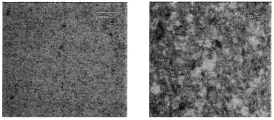
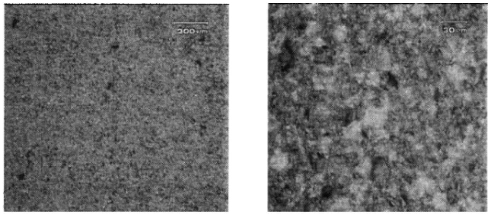
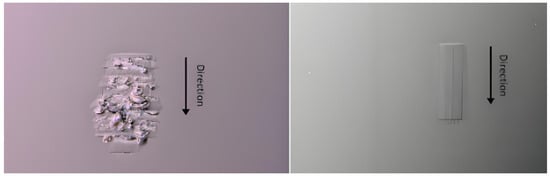
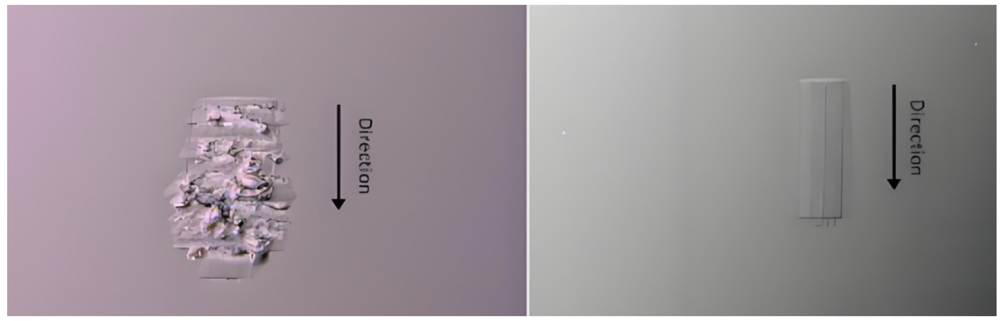
Figure 1 and Figure 2 are the optical micrographs of sapphire substrate before and after processing obtained by Meng Qing ping [22] according to his diamond micropower grinding wheel grinding.
Figure 1.
Optical micrograph of unprocessed sapphire substrate surface [22].
Figure 2.
Optical microscopy of sapphire substrate surface after processing [22].
Although the traditional magnetorheological single-point polishing process can achieve nano-scale roughness processing of free-form surfaces [23], in order to avoid motion interference, the diameter of the tool head is usually small and the linear speed is limited, resulting in low processing efficiency [24]. For sapphire-specific magnetorheological shaping, targeted improvements have been made: Yan Qiusheng’s team developed cluster magnetorheological polishing technology, which constructs semi-solidified ‘micro-grinding heads’ via magnetorheological effect and cluster principle—this design enables uniform abrasive distribution and cooperative grinding, effectively improving sapphire polishing efficiency while ensuring surface quality [17,25]; Lai Keming et al. further combined laser pretreatment with cluster magnetorheological polishing, and experimental results showed that this composite process significantly enhances the processing efficiency of sapphire substrates and reduces surface defects [26].
If the cylindrical magnetorheological polishing wheel is used, the hydrodynamic pressure and flow rate of the processing fluid can be effectively enhanced [27], and the processing efficiency can be improved. Aiming at the efficiency optimization of the magnetorheological process, Seok’s team [28] designed a tool head with a built-in cylindrical permanent magnet and a saddle-shaped cross-section for experiments. The results show that the structure not only improves the material removal rate but also weakens the edge effect. In order to further strengthen the processing efficiency, Ji et al. [29] deeply discussed the influence of the groove polishing wheel on the dynamic characteristics of the flow field, supplemented by fluid simulation. The analysis reveals that, compared with the grooveless wheel, the peak fluid dynamic pressure and shear flow velocity induced by the groove structure at the interface of the workpiece are significantly increased, and the uniformity of pressure distribution is also improved. Li Gang’s group [30] systematically studied the mechanism of the flow channel configuration (wedge, L-shaped, parabolic) on the fluid behavior of the polishing disc surface. Combined with theoretical modeling and numerical simulation, it is concluded that the parabolic flow channel exhibits the best hydrodynamic performance and produces the highest local pressure.
The pressure on the workpiece is related to the pressure and shear force during polishing. Peng et al. [31] analyzed the normal pressure and shear force in the magnetorheological polishing process and constructed the model. They also proposed the final surface roughness Ra model to predict the polishing performance. Ma et al. [32] constructed a shear force model to further explore the effect of shear force on polishing effect. They assume that the magnetic powder will exhibit shear behavior when sliding in the horizontal direction and introduce an exponential function to explain the correlation between the number of slips and the shear rate of the magnetic powder. Yang et al. [24,33] studied the formation principle of the shear force field in the entrance area of magnetorheological polishing, calculated the shear force distribution corresponding to the convex spherical optical element under different curvature radii and different immersion depths and drew conclusions through numerical analysis. It is found that the radius of curvature has little effect on the change in shear force when the immersion depth has a great influence, and the shear force at the entrance of the polishing zone increases with the increase in the immersion depth.
2.3. High Frequency Error Suppression: Polishing
Chemical mechanical polishing (CMP) technology [34,35] was first proposed by Nobuo. The researchers carried out polishing experiments on sapphire with silica sol as the medium. The final test shows that there is no damage to the surface of the workpiece after processing, and the surface roughness is at a low level. This study shows that chemical mechanical polishing can achieve non-destructive processing of hard and brittle materials such as sapphire. However, in the process of chemical mechanical polishing, there are problems such as low polishing efficiency and difficulty in recycling the polishing liquid after polishing.
Xu et al. [36] explored the influence of various process parameters on the polishing results in the chemical mechanical polishing process. They combined theoretical analysis with orthogonal experiments and found that when the pressure increased to 48.26 kPa, a balance was formed between mechanical stripping and chemical reaction. In this state, the material removal rate is 3.1 nm/h, and the surface roughness is 0.1 nm.
The working principle of hydration polishing technology [37] is that the workpiece reacts with high temperature water vapor to form a softening layer, and then the softening layer is mechanically peeled off by friction. In the whole process of hydration polishing, no chemical reagents and abrasives are added, and no pollutants are produced. It is a ‘green ‘processing method.
Wu Jianlin [38] studied the influence of different hole types on the polishing trajectory in the hydration polishing experiment and simulated the influence of hydration polishing on the workpiece under different temperature fields. The results show that the thickness of the reaction layer (i.e., softening layer) is about 2 nm after hydration polishing for 20 h, and the lattice of sapphire surface is not distorted. However, due to the low processing efficiency of hydration polishing and the unclear specific mechanism of the reaction during the processing process, the polishing method is not commonly used in actual production.
Magnetorheological polishing (MRP) technology can process substrate components without subsurface damage, so as to obtain substrates with excellent surface flatness [39]. However, there is still room for improvement in the research of magnetorheological fluid, and magnetorheological polishing has problems such as difficult control of the process, high manufacturing cost of magnetorheological fluid [40], inability to recycle after use, and certain pollution to the environment.
Laser polishing can effectively protect the surface layer [41], because it does not directly contact the workpiece during the polishing process, and the workpiece is not subjected to downward pressure, so no damage layer will be formed on its surface. However, the research on laser polishing is not yet mature: the removal mechanism of workpiece materials is not yet clear, and the reliability of theoretical model results is low. In addition, laser polishing equipment is complicated to manufacture and expensive, which is not conducive to industrial production.
Nusser et al. [42] proposed a laser polishing technique for metal substrates. Their research found that the polished surface of the material not only retains the characteristic morphology corresponding to the initial surface roughness, but also presents some new morphologies brought by the polishing process (these new morphologies are characterized by different surface roughness).
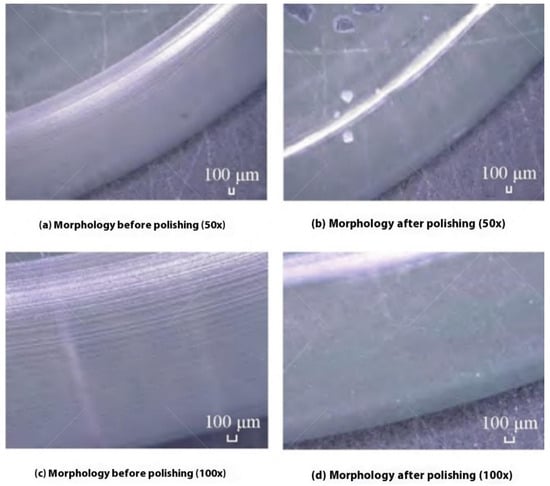
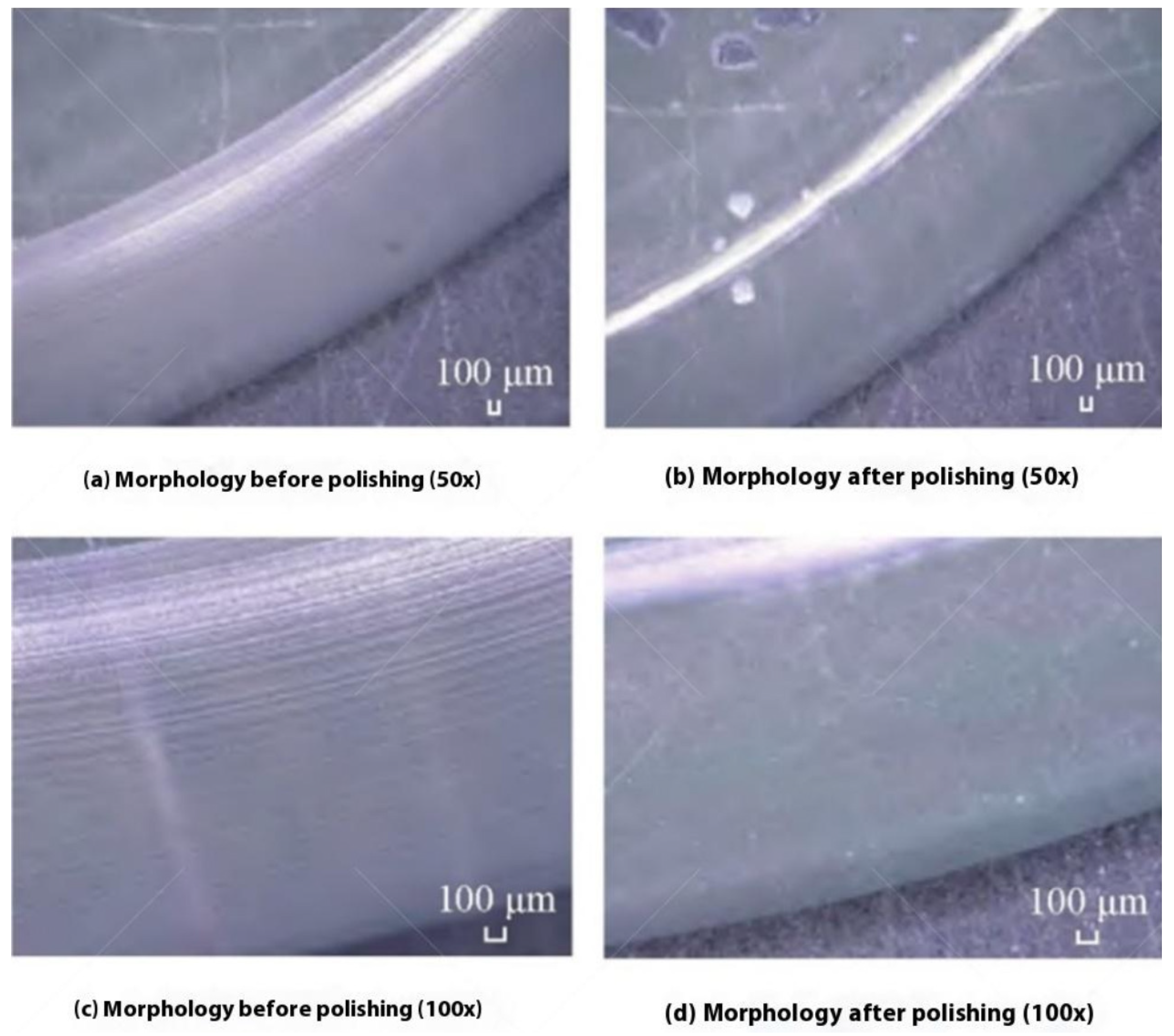
Ballonet polishing is a kind of fast polishing method, which has the characteristics of high efficiency and stable removal function. At present, robot bonnet polishing technology has been widely used in various scenarios, and its advantages are reflected in low cost and strong flexibility [43,44,45,46]. Based on this background, Fu [47] proposed a rapid processing scheme for polishing sapphire by robot airbag, aiming at improving the polishing efficiency of materials and reducing surface roughness. In the specific research, firstly, the airbag polishing removal model and the robot pose transformation model are established, and combined with the Preston equation, the level of factors affecting the airbag polishing effect is analyzed. Subsequently, the obtained optimal factor level is used for experimental verification; after that, under the optimal process parameters, the influence of polishing time on the surface quality of sapphire is further studied. Finally, the feasibility of the process of polishing sapphire surface by balloon is verified by experiments. Figure 3 shows the surface morphology of the front and rear arc surfaces at different magnifications under bonnet polishing.
Figure 3.
Arc surface morphology before and after bonnet polishing [47].
3. Nano-Precision Intrinsic Surface Controllability Generation Method
3.1. Mechanical Surface Defects-Immersed Polishing
The dielectrophoresis effect refers to the phenomenon that particles move due to dielectric polarization in a non-uniform electric field [48,49]. The first application of this effect in the field of polishing was performed by Kim et al. [50,51]. In their research, the dielectrophoresis effect of abrasive particles such as Al2O3, diamond, and silicon carbide in the suspension in the non-uniform electric field was used to promote the directional movement of the abrasive and gather near the polishing tool head, thus realizing the efficient utilization of the abrasive. The domestic research team has carried out relevant explorations around the dielectrophoresis effect in the field of polishing processing. Lin et al. [52] and Zhao et al. [53] deduced the force acting on the abrasive in the non-uniform AC electric field from the theoretical level; Zhao et al. [54]. further observed the morphological changes in polished droplets in the non-uniform AC electric field experimentally to verify the derivation results, and then the processing principle and removal mechanism of dielectrophoresis polishing were clarified. Dielectrophoretic polishing is applicable in the processing of hard and brittle materials.
Zhao et al. [55] used dielectrophoresis polishing (DEEP) to treat silicon wafers. Compared with traditional chemical mechanical polishing (CMP), the material removal rate (MRR) of DEEP increased by 17.6%, and the final surface roughness Ra of silicon wafers decreased to 0.31 nm. It can be seen that this technology can achieve efficient and high-quality processing of silicon wafers. Zhang et al. [56] constructed a single-layer abrasive friction and wear erosion model for high-speed abrasive flow composite polishing technology based on dielectrophoresis effect and a material removal model for self-excited oscillation pulsed abrasive flow polishing. The experimental results show that this method can effectively improve the adsorption amount of SiO2 abrasive particles, and the abrasive removal efficiency is as high as 98%.
Wang Jiahuan et al. [57] proposed to apply the dielectrophoresis effect to the high-speed polishing process and carried out simulation and experimental research on the electrode distribution during high-speed polishing. It is found that there is a correlation between the distribution characteristics of the non-uniform electric field and the arrangement of the electrodes, which will further affect the stress state. Among them, the greater the difference in potential distribution, the more obvious the dielectrophoresis effect. After the electrode plate was arranged in a cross manner, the polishing experiment was carried out on the glass plane, and a higher material removal rate of 1.75 μm/min was finally obtained.
Deng et al. [14] explored the effect of the same layer arrangement of positive and negative electrodes on the polishing effect. Through simulation analysis and experimental verification, it was found that when this arrangement was used to polish the silicon wafer, the material removal rate was 27.3% higher than that of ordinary chemical mechanical polishing (CMP). Practice shows that the combination of dielectrophoresis effect and chemical mechanical polishing (CMP) can effectively improve the utilization efficiency of abrasives in the CMP process.
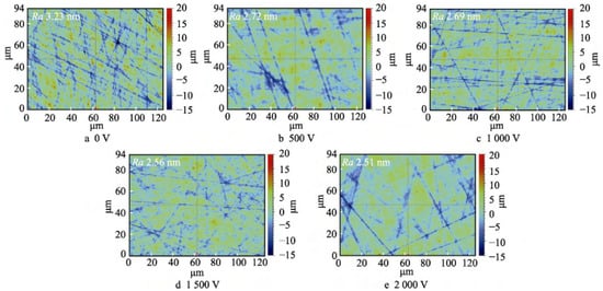
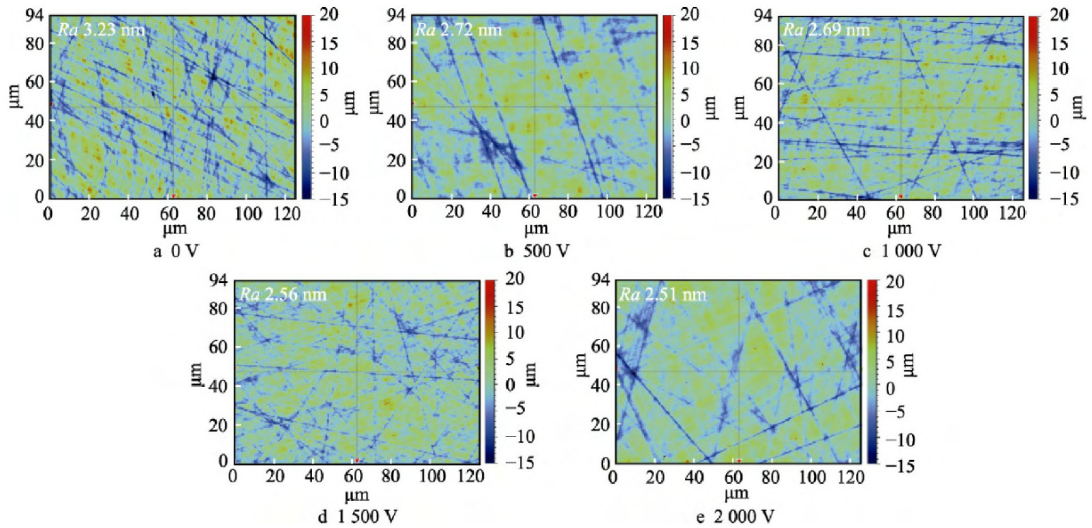
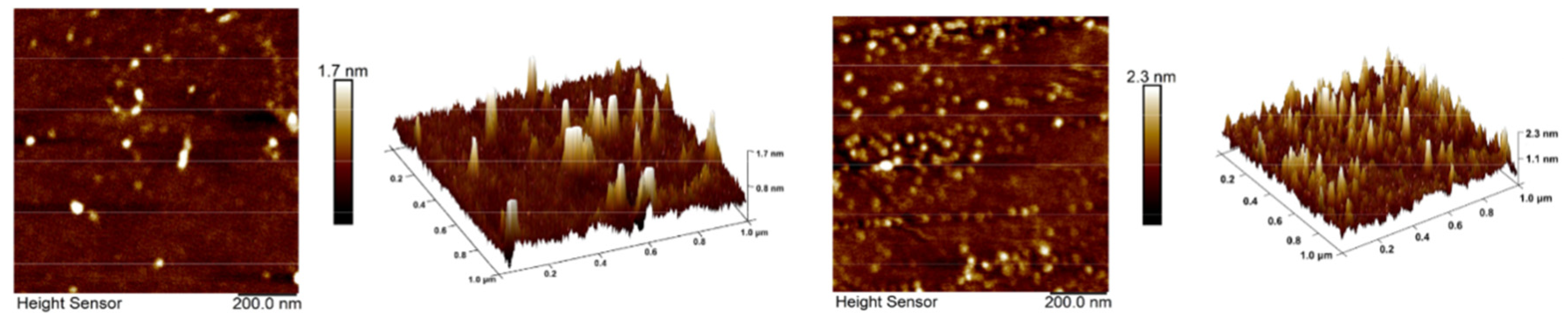
Figure 4 shows the surface morphology results of immersion polishing under different voltages. The surface roughness (Ra) varies with the voltage. For example, Ra is 3.23 nm at 0 V and 2.51 nm at 2000 V. This intuitively shows the influence of voltage on the polishing effect, which corresponds to the content of voltage-regulated processing quality in the study of dielectrophoresis polishing, and provides morphological data support for exploring the optimization of polishing parameters under dielectrophoresis effect.
Figure 4.
Dielectrophoretic polishing results under different voltages: (a) 0 V, (b) 500 V, (c) 1000 V, (d) 1500 V, (e) 2000 V [58].
3.2. Contaminated Defect-Large Beam Ion Beam Cleaning
In the research field of intrinsic surface control of sapphire nano-precision, the pollution defects generated by the processing link have become the core obstacle to limit its performance breakthrough. In the process of cutting, grinding, and polishing, the surface of sapphire will not only form visible scratches, but also its sub-surface area is more likely to be contaminated by impurities such as metal ions and abrasive particles due to residual grinding media, adsorption of environmental impurities, and chemical reactions. These defects disturb the ordered arrangement of surface atoms, greatly weaken the laser loading capacity and optical uniformity of the components, and struggle to meet the stringent requirements of high-end application scenarios such as high-power lasers and semiconductors for nanoscale surface quality.
The traditional process draws on the idea of semiconductor material treatment, introduces the AMP Mega sonic acid pickling process of NIF from the United States [58], uses a certain concentration of HF acid as the etching solution to soak the sapphire workpiece, and removes the pollution layer through chemical corrosion, thereby increasing the laser damage threshold. However, this method has serious drawbacks in practical applications. On the one hand, sapphire crystals have significant anisotropy, which makes it difficult to achieve precise control of the acid etching process, and it is easy to cause surface shape distortion, which runs counter to the goal of nano-precision surface control. On the other hand, the solubility of aluminum fluoride and other products formed by the reaction of HF acid and sapphire is limited, and secondary pollution is formed after deposition, which further deteriorates the intrinsic characteristics of the surface and aggravates the risk of performance degradation.
To effectively overcome the above problems, two typical technologies have been studied: Surat Wala et al. [11] proposed an HF-based etching process to improve the laser damage threshold, while Chen et al. [59] adopted ion etching with physical sputtering effect to realize nano-precision removal of contaminated layers using the ion etching process with the physical sputtering effect as the core and using the high-energy ion beam emitted by the focused ion source to bombard the sapphire surface. When the energy obtained by the surface atoms exceeds the lattice binding energy, the atoms are detached from the surface, and the nano-precision removal of the contaminated layer and the damaged material is achieved. This process can not only effectively remove the nano-dot microstructure absorption precursor but also does not introduce chemical impurities and stress defects throughout the process, which fundamentally guarantees the intrinsic characteristics of the surface atomic arrangement and lays a high-quality foundation for subsequent processing.
It is worth noting that although most of the pollution layers are removed from the sapphire surface after ion etching, fine impurities may still remain, and secondary pollution risks are faced in subsequent processes (such as vacuum coating). In order to solve the above problems, the end-Hall ion source has become the preferred solution for ion beam cleaning due to its unique advantages of low energy and high beam current [60]. In the key link before vacuum coating, sapphire substrate is easy to be contaminated by pollutants in the process of clamping or vacuuming, and ion beam cleaning achieves deep cleaning through physical and chemical dual mechanism. On the surface, the ions collide with the dirt on the surface of the substrate to produce a sputtering effect, which promotes the separation of the adsorbed or adhered impurities; at the molecular level, the oxidation reaction between high thermal energy oxygen ions and contaminants makes the products easier to be removed by ion collision. The experimental data show that after ion beam cleaning, not only are the polishing powder particles on the sapphire surface completely removed [15], but the surface morphology is significantly improved, and the surface free energy is significantly improved.
According to Young’s formula [61]
σ2 = σ1 + σ0 ∗ cos θ
When σ0 and σ1 remain unchanged, the contact angle θ of water droplets decreases and cos θ increases, which in turn increases the surface energy σ2 and creates better substrate conditions for film growth.
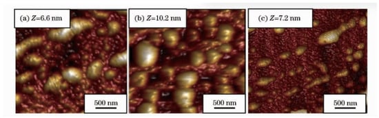
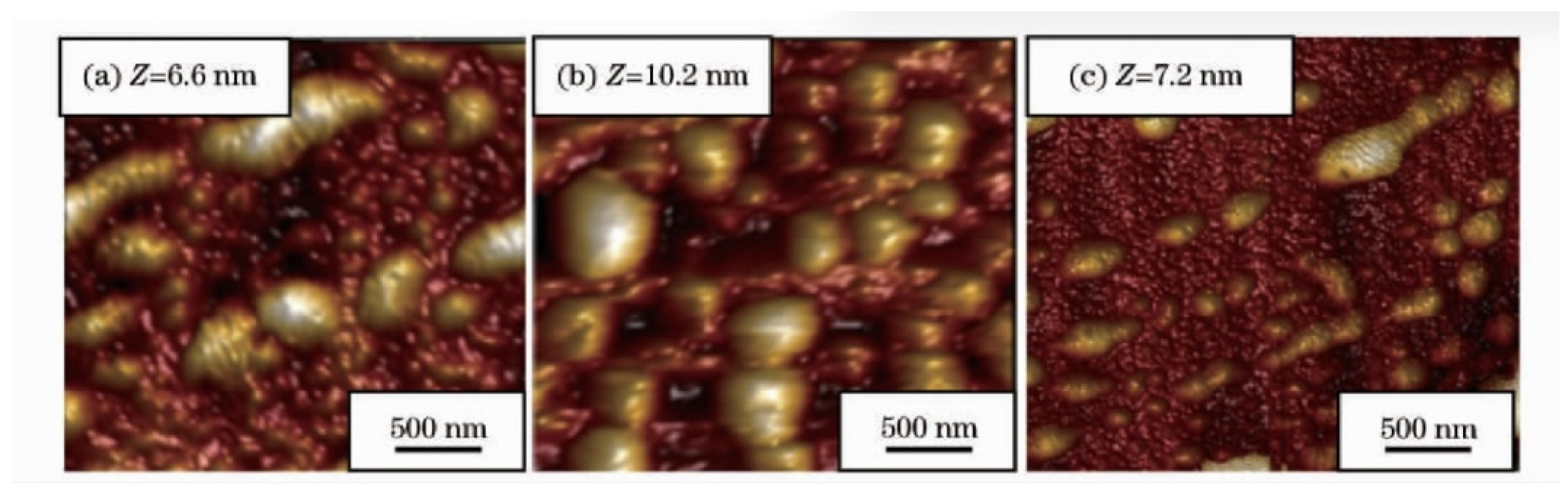
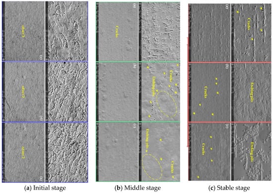
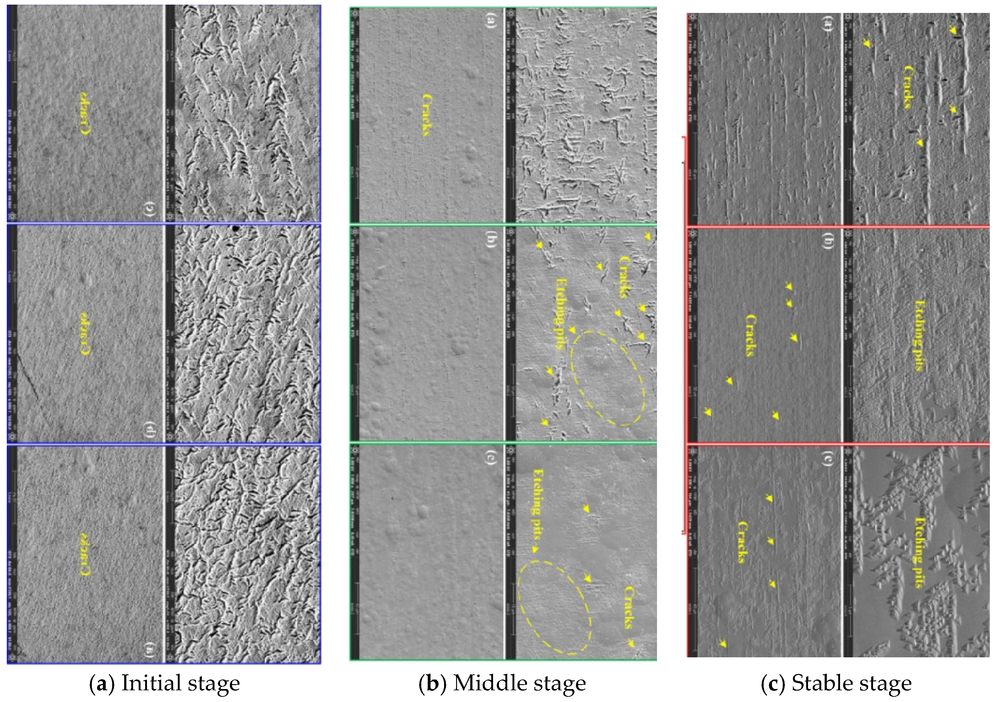
In terms of improving the laser performance of sapphire elements, ion etching and ion beam cleaning technology show a strong synergistic effect. Ion etching eliminates deep pollution from the perspective of material removal, and ion beam cleaning eliminates secondary pollution in the surface cleaning dimension. The two work together to effectively avoid the thermal–mechanical coupling damage caused by local temperature rise during laser irradiation of thin films. At the same time, the increase in surface energy after cleaning promotes the two-dimensional growth of the film, enhances the adhesion between the film and the substrate, and finally significantly improves the laser damage resistance of the film. This whole process of collaborative processing from material removal, surface cleaning, to film performance optimization realizes the all-around improvement of intrinsic surface control of sapphire nano-precision, which provides reliable technical support for its wide application in high-end fields. Figure 5 is the sapphire cleaning diagram under different ion beam parameters, which can better show the characteristics of the technology.
Figure 5.
Cleaning diagram of sapphire under different ion beam parameters.
3.3. Structural Defect-Ion Beam
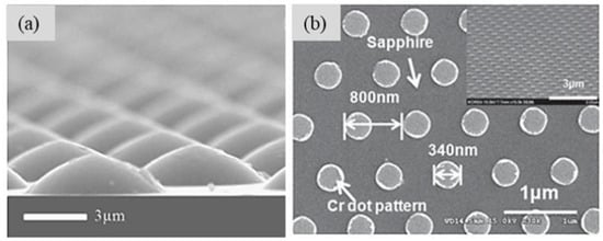
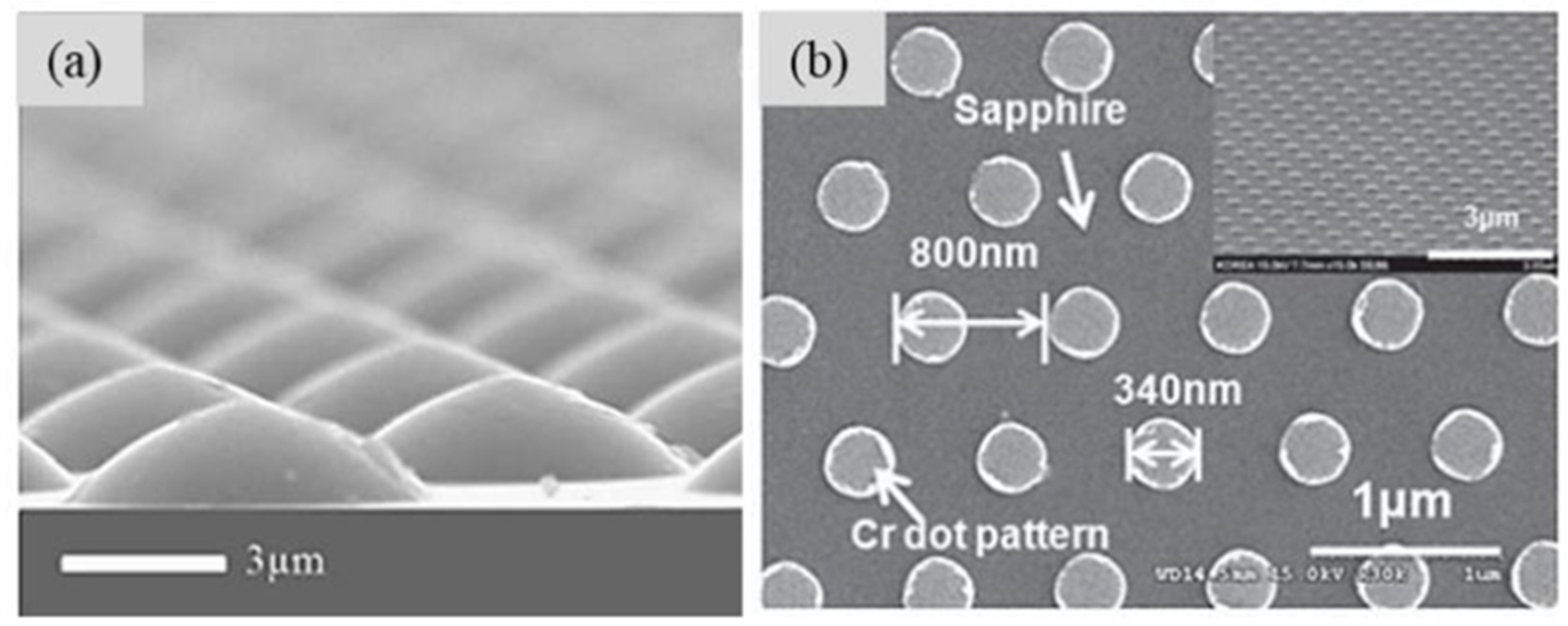
Many researchers have optimized the process parameters of sapphire substrate patterning by RIBE and ICP [62,63,64,65,66]. Suthan Kissinger et al. [63] studied the influence of ion beam incident angle, incident energy, beam current density and action time on the surface structure of sapphire after etching. Etching sapphire crystal under the optimized ion beam parameters can generate a good lens shape structure on its surface, as shown in Figure 6.
Figure 6.
(a) Lens shape structure etched by optimized ion beam parameters (b) sapphire pattern etched by ICP [66].
Y.P. Hsu et al. [66] used Cl2, BCl3, and CH2Cl2 as reaction gases to study the relationship between etching rate and mixed gas ratio when ICP etching sapphire. Hyoungwon Park et al. prepared high-period nano-patterns on 2-inch sapphire substrates by nano-imprint lithography and ICP technology.
4. Nanometer Precision Control Shape Combination Process
In order to achieve the goal of shape control of nano-precision surfaces, domestic and foreign research teams use a combination of high-precision and low-defect combination processes. Different from the simple connection and transformation of each process in traditional processing, this kind of combined process reasonably allocates the achievement of each index to the whole process flow and then realizes the shape-control and controllable manufacturing of sapphire components with high precision and low defects.
4.1. Sapphire Composite Synergistic Polishing Technology
In the sapphire wafer surface polishing technology, a single polishing method such as magnetorheological polishing, ultrasonic vibration polishing, etc., often has a high material removal rate or high surface quality. Between the two, the method cannot have both, and thus cannot meet the actual production and processing requirements [67,68,69]. Therefore, driven by the market demand, the composite polishing technology, which is the organic combination of two or more polishing technologies, came into being [70,71,72].
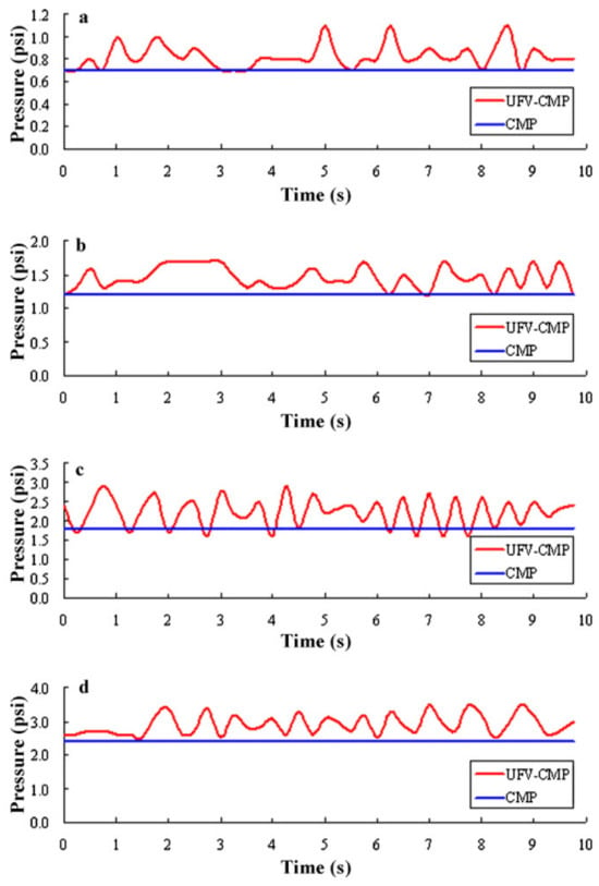
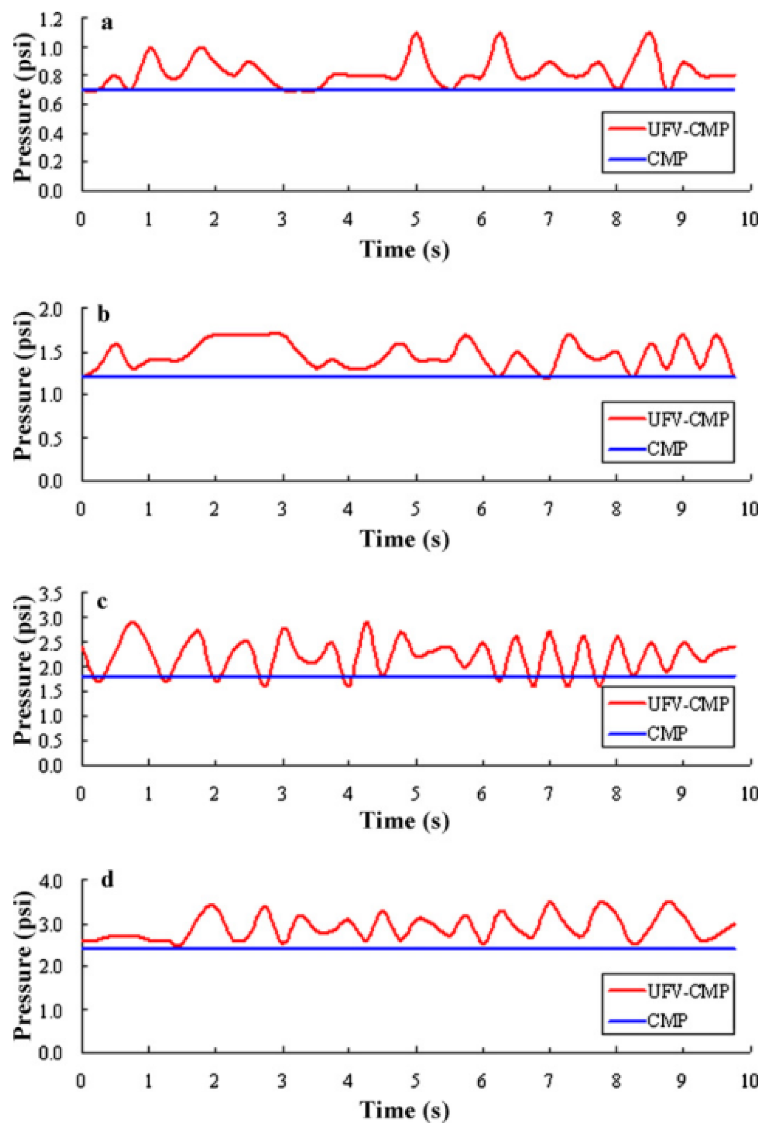
From 2010 to 2011, Pan Guoshun’s team [16] at Tsinghua University used elliptical ultrasonic vibration chemical mechanical polishing (UFV-CMP) to finish the surface of single crystal sapphire. The sapphire wafer can obtain ultrasonic vibration in both horizontal and vertical directions at the same time, as shown in Figure 7. Compared with the traditional chemical mechanical polishing, the experimental results (n = 3, repeated 3 times for each group) show that the composite polishing technology can reduce the surface roughness of the sapphire wafer to Ra = 0.083 ± 0.005 nm (standard deviation σ = 0.005 nm), which is 2.5 times lower than that of traditional CMP (Ra = 0.208 ± 0.012 nm). The flatness is reduced from 0.23 ± 0.015 μm to 0.12 ± 0.008 μm, and the material removal rate is twice that of traditional CMP [18].
Figure 7.
Comparison between bending ultrasonic vibration assisted chemical mechanical polishing and traditional chemical mechanical polishing [16]. (a) Pressure variation with time under Condition 1. (b) Pressure variation with time under Condition 2. (c) Pressure variation with time under Condition 3. (d) Pressure variation with time under Condition 4.
From 2012 to 2014, Yan Qiusheng’s research team of Guangdong University of Technology [17,25] successfully developed cluster magnetorheological polishing technology based on the magnetorheological effect and cluster principle (the specific structure is shown in Figure 8). The core of this technology is as follows: firstly, the abrasive particles are added to the magnetorheological fluid, and then the semi-solidified ‘micro-grinding head’ is constructed by using the magnetorheological effect based on the micro-magnetic unit embedded in the polishing pad of the diamagnetic substrate. These microstructures can effectively bind the free abrasive particles. At the same time, the array arrangement of micro-magnets induces the formation of a specific magnetic field configuration, which promotes the formation of multiple magnetic beams grinding head clusters in the polishing film area, and the grinding particles can be evenly distributed in them. During the polishing process, the workpiece and the polishing disc perform synchronous rotation motion. With the help of the cooperative grinding effect of the cluster micro-grinding head, the precision machining of high-quality surface is finally realized.
Figure 8.
Cluster magnetorheological polishing process of sapphire: [17,25].
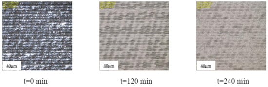
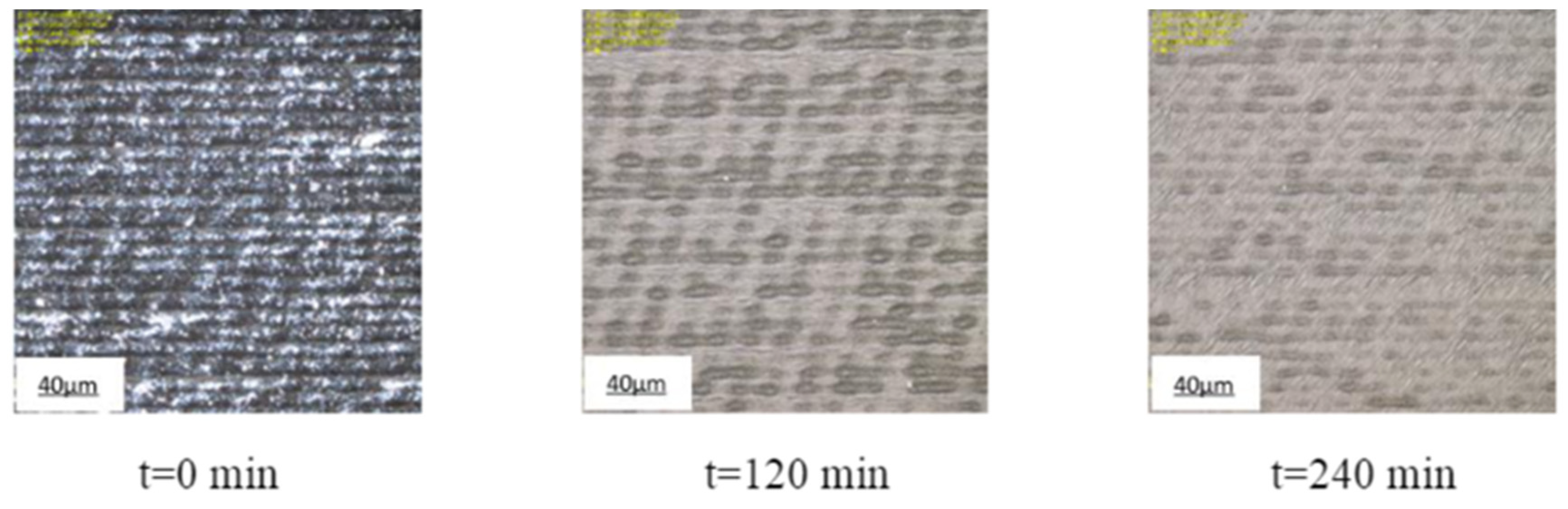
To further improve the processing quality and efficiency of cluster magnetorheological polishing for sapphire, Lai Keming et al. [26]. introduced laser pretreatment into the process: by pretreating the sapphire surface with laser, the surface activation and material removal uniformity were enhanced. The experimental results showed that the surface morphology of sapphire changed significantly with the extension of cluster magnetorheological polishing time after laser pretreatment (Figure 3), and the surface defects were further reduced compared with the traditional cluster magnetorheological polishing process. Figure 9 is Yan Qiu sheng’s [26] team’s sapphire in the laser pretreatment sapphire cluster magnetorheological polishing process with the change in time.
Figure 9.
The surface morphology of sapphire cluster magnetorheological polishing changes with processing time (t represents processing time; t = 120 min, t = 240 min) [26].
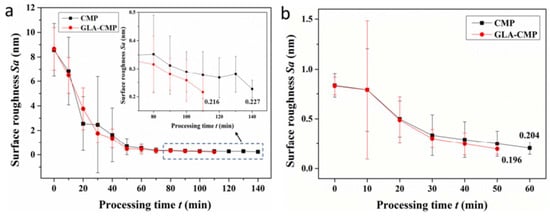
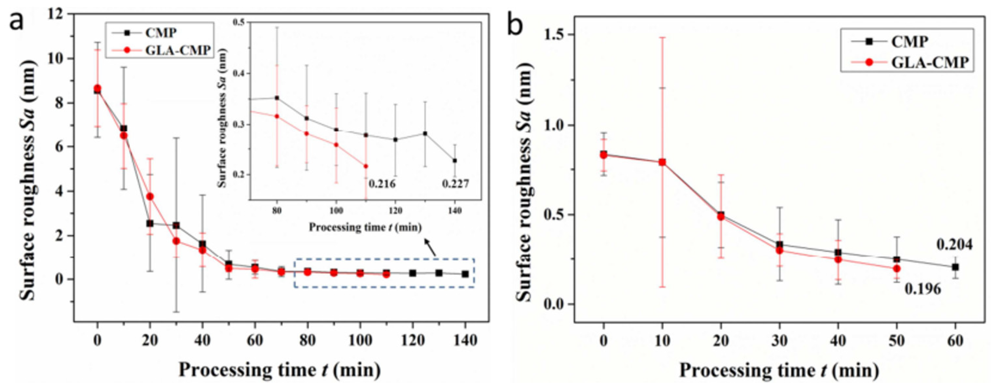
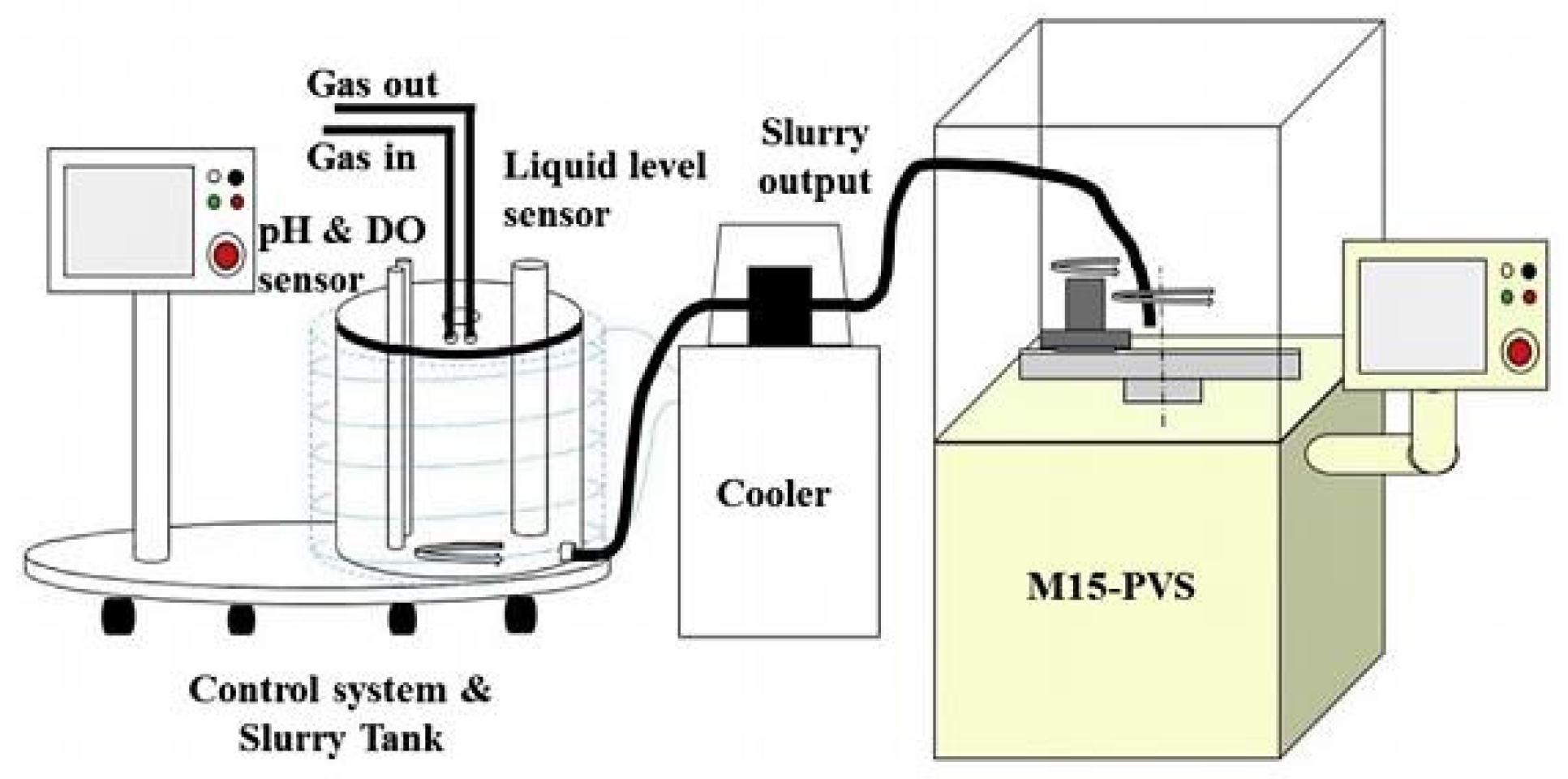
In 2018, Chen Gang of Xi’an University of Technology [73] used cluster magnetorheological technology to carry out polishing experiments on sapphire. The experimental results show that when the pH value of the polishing solution is 10, the abrasive concentration is 45%, the pressure is maintained at 280 N, the temperature is controlled at 39 °C, and the speed of the polishing disc is set to 25 r/min, the surface roughness Ra of the sapphire can be reduced to 0.8 nm after 60 min of polishing. Xu Xipeng et al. [74] of Huaqiao University combined the vapor-liquid-assisted chemical mechanical polishing (GLA-CMP) technology with semi-fixed abrasive polishing to implement ultra-precision polishing of sapphire wafers, and carried out comparative experiments with ordinary chemical mechanical polishing. Figure 10 is the roughness comparison of the two processes. It is found that the material removal rate of this composite polishing technology can reach 77.6 nm/min, which is 10.23% higher than that of ordinary chemical mechanical polishing. After 110 min of polishing, the surface roughness Ra of the wafer can reach 0.2 nm. The experimental device of vapor-liquid-assisted chemical mechanical polishing (GLA-CMP) technology is shown in Figure 11.
Figure 10.
Roughness of ultra-precision polishing and ordinary chemical mechanical polishing at different times [74]. (a) Variation of surface roughness Sq and Sa with processing time. (b) Variation of surface roughness Sa with processing time.
Figure 11.
Vapor-liquid-assisted chemical mechanical polishing [74].
In 2021, Cheng Yuanyao [75] of Nanchang University analyzed the effect of different experimental parameters on the ultrasonic chemical mechanical polishing of sapphire wafers by means of orthogonal test. The experimental results show that the working pressure between the wafer and the polishing disc is the most prominent among the various process parameters affecting the material removal rate of sapphire. As for the polishing parameters that have the most significant influence on the surface roughness, it is the relative speed of the wafer and the polishing disc. Figure 12 is the influence of different experimental parameters on the effect of ultrasonic chemical mechanical polishing of sapphire wafers. It is worth noting that the introduction of ultrasonic vibration can improve the polishing efficiency of sapphire from the two dimensions of chemical reaction and mechanical action.
Figure 12.
Effects of different experimental parameters on the results of ultrasonic chemical mechanical polishing of sapphire wafers [75].
4.2. Sapphire Auxiliary Polishing Technology
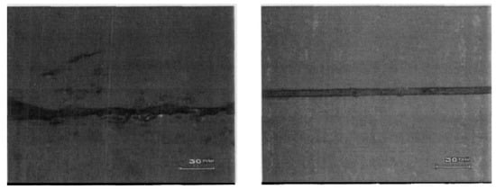
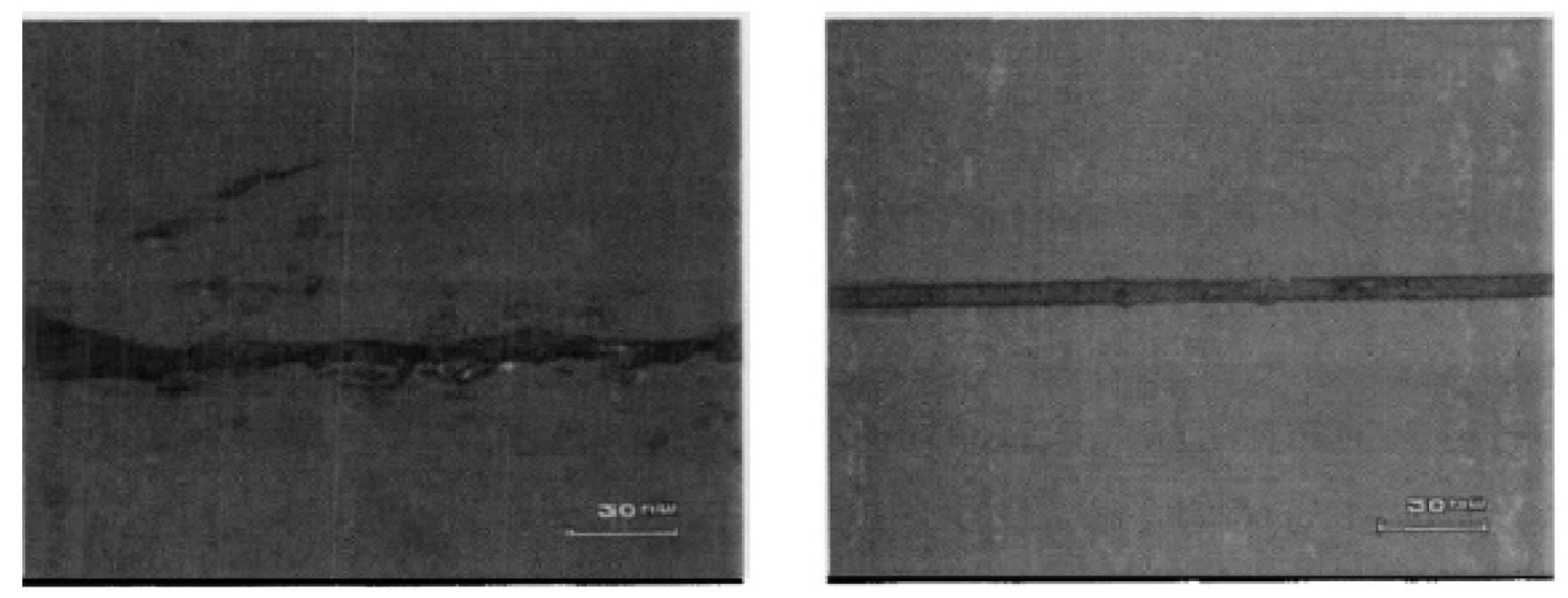
The micro-laser assisted machining (μ-LAM) used by Sean et al. [76] of Rutgers University in the United States is a process with significant advantages. The process is based on single-point diamond turning (SPDT). By focusing the laser on the processing point, the thermal softening effect is used to reduce the hardness of sapphire (up to 50%), thereby promoting the brittle–ductile transition, allowing the material to achieve plastic yield and ductility removal, reducing the common cracks, microcracks, and other damages in traditional processing, and the in situ annealing effect of the laser is also used to alleviate defects such as stacked faults and amorphous regions. Compared with traditional single-point diamond turning, μ-LAM can effectively reduce the residual stress after processing, especially at higher laser power, which can significantly reduce the phenomena of fracture, cracking, and edge collapse. By controlling the laser parameters (such as wavelength and power), the precise control of the processing area can be realized, and the precision control of the surface morphology (such as the notch width of about 2 μm) and the suppression of near-surface damage can be achieved. This combined process greatly improves the surface quality and material performance stability while ensuring the contour accuracy of sapphire optical components and provides a feasible path for high-efficiency and low-damage processing of hard brittle transparent materials. Figure 13 is the comparison of the processing effect of traditional single-point diamond turning and micro-laser assisted machining.
Figure 13.
Traditional single-point diamond turning (left) micro-laser assisted machining (right) [76].
In order to study non-damage or low-damage sapphire processing, Sheng Wang et al. [77] used the high positioning accuracy (sub-micron contour convergence) and high stiffness spindle of ultra-precision grinding to achieve accurate control of complex surfaces such as aspheric surfaces and free-form surfaces. At the same time, the damage was suppressed by small grinding depth and fine-grained grinding wheels to form a ductile grinding surface. The surface roughness was reduced to Ra 8 nm, the subsurface damage depth was controlled at 4.8 μm, and the difference between the internal and external damage of the workpiece was small, which laid a low damage foundation for subsequent processing.
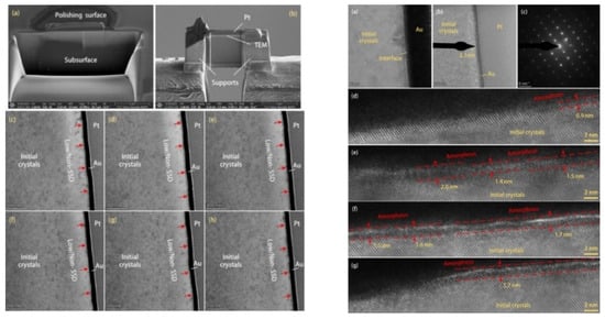
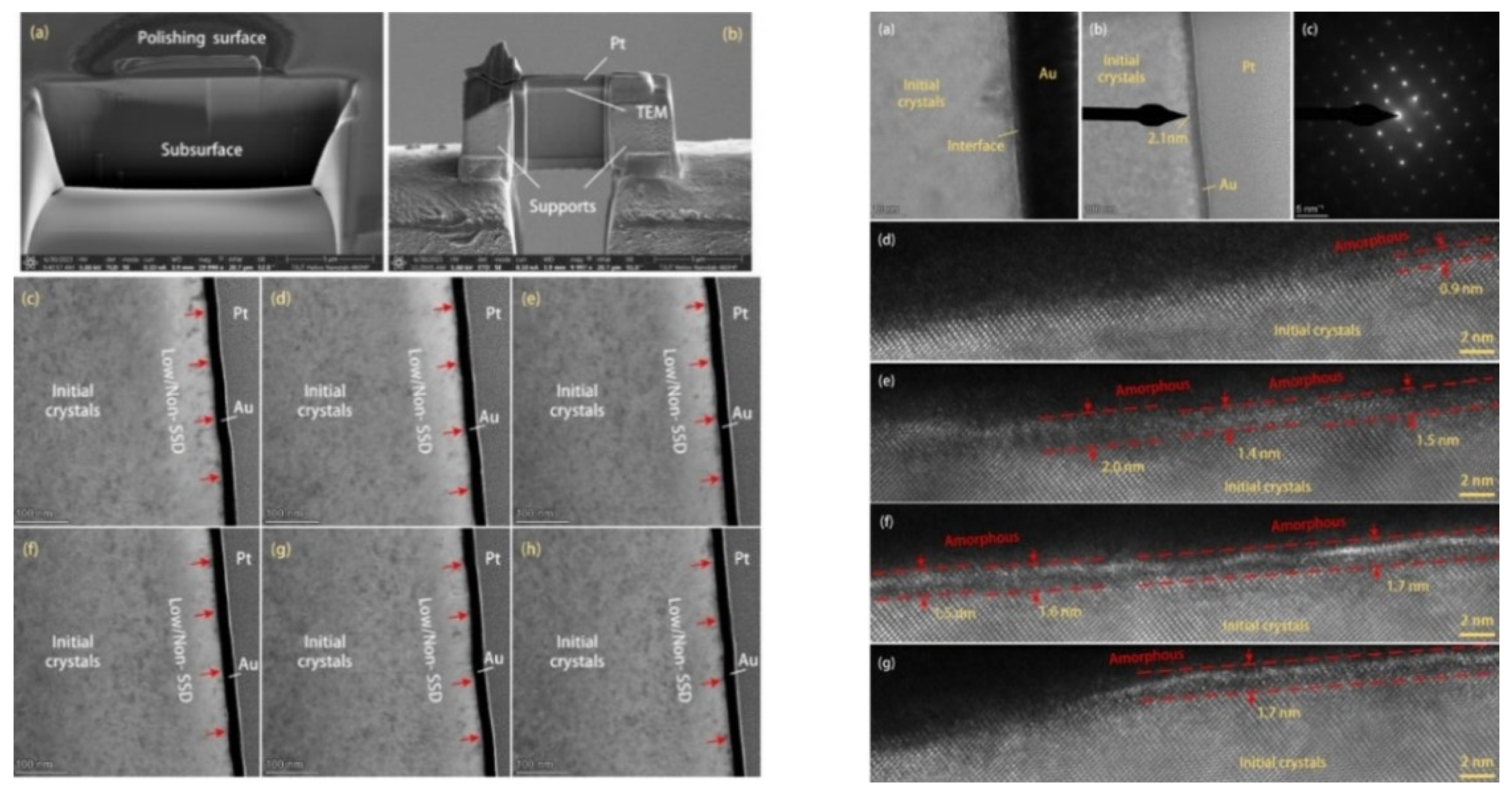
In the subsequent polishing process, different grinding strategies directly affect the control effect. Ultra-precision grinding can shorten the damage removal time by 1/4. Combined with photothermal absorption monitoring, the subsurface damage evolution under the Beilby layer can be tracked. Finally, the scratch-dominated subsurface damage can be eliminated by ion beam polishing. The FIB and TEM characterizations show that there is only an amorphous structure of <2 nm on the subsurface, and most of the atoms are arranged intact to achieve near-atomic damage control. An efficient shape-control and control process chain of ‘ultra-precision grinding-polishing-ion beam polishing’ is constructed, which takes into account surface accuracy and damage suppression to meet the performance requirements of sapphire optical components in harsh environments. Figure 14 is based on the subsurface characteristics and subsurface atomic structure of sapphire processed by this composite process chain, which can more clearly reflect the advantages of this technology.
Figure 14.
Subsurface characteristics and subsurface atomic structure of sapphire processed by composite process chain [77].
The “coarse grinding-semi-fine grinding-ultra-precision grinding” step strategy adopted by Wang et al. [78] is a way to achieve high efficiency and low damage processing. Firstly, the basic forming is completed by a D25 grinding wheel in the coarse grinding stage, and the subsurface damage depth increases with the increase in grinding depth, so the control parameters are needed to avoid excessive damage. Secondly, semi-precision grinding introduces multi-pass processing (such as 10 passes); combined with medium-grained grinding wheels, it can effectively remove deep cracks generated by rough grinding, reduce surface roughness, and lay the foundation for ultra-precision grinding. Then, ultra-precision grinding uses a small-grained grinding wheel (such as D7). With the high stiffness and low vibration characteristics of the total static pressure module, the subsurface damage depth is controlled at 3.9 μm, and the difference between the internal and external damage of the workpiece is suppressed by cross grinding, so that the ductile domain processing with surface roughness < 10 nm can be realized. The process combines cross-section polishing, focused ion beam (FIB), ion beam polishing and other characterization methods to reveal the gradient distribution law of subsurface cracks, and the damage scale is evaluated by photothermal absorption technology. Finally, a damage prediction model suitable for the combined strategy is established. While ensuring the convergence of contour accuracy (especially aspheric and free-form surfaces), the model reduces the material removal of subsequent polishing, balances shape control and performance regulation, and provides a systematic solution for the efficient and low-damage manufacturing of sapphire optical components. Figure 15 is a sapphire element under the three-layer step processing strategy.
Figure 15.
Stepped machining of coarse grinding-semi-fine grinding-ultra-precision grinding [78].
5. Conclusions
As a high-performance hard and brittle material, sapphire’s nano-precision shape-controlled manufacturing technology is crucial in aerospace, optoelectronic systems and other fields. At present, precision control of surface morphology and defects has been achieved through multi-wire cutting, magnetorheological polishing, laser processing and other processes. For example, magnetorheological polishing (sample size n = 5) can reduce the low-frequency surface shape error from 200 ± 12 nm to 25 ± 3 nm (standard deviation σ = 3 nm), and femtosecond laser combined with chemical etching (n = 3) can stably prepare nanoscale microstructures with a size deviation of less than ±10%. However, it still faces challenges such as low processing efficiency, imperfect mechanism model, and insufficient adaptability to extreme environments. In the future, it is necessary to focus on green composite processing, intelligent modeling, and high-temperature damage resistance modification to promote the development of technology to high-efficiency, intelligent, and extreme applications.
Author Contributions
S.Q.: Investigation, Data curation, Formal analysis, Writing—original draft. Y.L.: Investigation, Writing—original draft. Z.H. (Zhangfu Huang): Data curation, Formal analysis. Z.H. (Ziqiang Hu): Investigation, Data curation. W.T.: Resources, Supervision. All authors have read and agreed to the published version of the manuscript.
Funding
This study was financially supported by the National Natural Science Foundation of China (62575308, 62375019), the China Postdoctoral Science Foundation under Grant Number 2024M764130.
Conflicts of Interest
The authors declare that they have no known competing financial interests or personal relationships that could have appeared to influence the work reported in this paper.
References
- Yang, G.; Peng, Z.; Wang, Y.; Sun, P.; Shang, P.; Lian, W.; Yang, X.; Liu, H.; Yang, G.; Yang, M.; et al. Numerical study of thermal shock on infrared windows and their composites with diamond coatings under harsh conditions. Diam. Relat. Mater. 2023, 137, 110117. [Google Scholar] [CrossRef] [Scilit]
- Nie, H.; Lu, B. Sapphire window and it’ s application in military electro–optical equipment. Ship Electron. Eng. 2005, 25, 131–133. [Google Scholar]
- Wu, S.; Li, C.; Xia, L. The optoelectronic applications and development trends of sapphire crystal materials. Yunguangjishu 2012, 44, 1–7. [Google Scholar]
- Li, J.; Su, X.; Na, M.; Li, N.; Yang, P.; Li, Y. Research trends and current status in producing sapphire domes. J. Synth. Cryst. 2007, 36, 467–474. [Google Scholar]
- Zhang, Y.; Pan, G.; Li, F. Research of metallic mesh in improving electromagnetic shielding of air-to-air missile. Infrared Technol. 2010, 32, 395–398. [Google Scholar]
- Liu, X.-Q.; Zhang, Y.-L.; Li, Q.-K.; Zheng, J.-X.; Lu, Y.-M.; Juodkaziset, S.; Chen, Q.-D.; Sun, H.-B. Biomimetic sapphire windows enabled by inside-out femtosecond laser deep-scribing. PhotoniX 2022, 3, 1. [Google Scholar] [CrossRef] [Scilit]
- Kang, R.; Tian, Y.; Guo, D. An Ultra-Precision Grinding Wheel for Hard and Brittle Crystal Substrates. China Patent CN200710016890.5, 15 December 2007. [Google Scholar]
- Arif, M.; Zhang, X.; Rahman, M.; Kumar, S. A predictive model of the critical undeformed chip thickness for ductile-brittle transition in nano-machining of brittle materials. Int. J. Mach. Tools Manuf. 2013, 64, 114–122. [Google Scholar] [CrossRef] [Scilit]
- Li, Z. Research on the Formation Mechanism and Suppression Technology of Grinding Damage of RB-SiC Ceramics. Ph.D. Thesis, Harbin Institute of Technology, Harbin, China, 2019; pp. 35–44. [Google Scholar]
- Yang, M.; Li, C.; Zhang, Y.; Jia, D.; Zhang, X.; Hou, Y.; Li, R.; Wang, J. Maximum undeformed equivalent chip thickness for ductile-brittle transition of zirconia ceramics under different lubrication conditions. Int. J. Mach. Tools Manuf. 2017, 122, 55–65. [Google Scholar] [CrossRef] [Scilit]
- Suratwala, T.I.; Miller, P.E.; Bude, J.D.; Steele, W.A.; Shen, N.; Monticelli, M.V.; Feit, M.D.; Laurence, T.A.; Norton, M.A.; Carr, C.W.; et al. HF based etching processes for improving laser damage resistance of fused silica optical surfaces. J. Am. Ceram. Soc. 2011, 94, 416–428. [Google Scholar] [CrossRef] [Scilit]
- Peng, Z.; Wang, X.; Lu, J. Method of imaging performance deterioration analysis and its experiment simulated high heating sapphire MW infrared window during near–hypersonic flight. Acta Phys. Sin. 2013, 62, 230702. [Google Scholar] [CrossRef] [Scilit]
- Chen, Y.; Ding, P.; Fu, C. Research on sapphire cutting process. Equip. Electron. Prod. Manuf. 2016, 45, 38–41. [Google Scholar]
- Deng, Q.F.; Cheng, J.; Lyu, B.H.; Yaun, J.; Wang, X.; Qian, K. Numerical Simulation and Experiments of SLAEs for Planar Polishing with Dielectrophoresis Effect. China Mech. Eng. 2022, 33, 1772–1779. [Google Scholar]
- You, D.; Huang, X.; Wu, J. Hall plasma source for auxiliary coating. Opt. Instrum. 2001, 23, 58–62. [Google Scholar]
- Xu, W.; Lu, X.; Pan, G.; Lei, Y.; Luo, J. Ultrasonic flexural vibration assisted chemical mechanical polishing for sapphire substrate. Appl. Surf. Sci. 2010, 256, 3936–3940. [Google Scholar] [CrossRef] [Scilit]
- Yan, J.W.; Yan, Q.S.; Lu, J.B.; Gao, W.Q.; Huang, Z.Y. Experimental research on smooth surface-polishing based on the cluster magnetorheological effect. Proc. Precis. Eng. Nanotechnol. 2012, 516, 79–83. [Google Scholar] [CrossRef] [Scilit]
- Xu, W.; Lu, X.; Pan, G.; Lei, Y.; Luo, J. Effects of the ultrasonic flexural vibration on the interaction between the abrasive particles; pad and sapphire substrate during chemical mechanical polishing (CMP). Appl. Surf. Sci. 2011, 257, 2905–2911. [Google Scholar] [CrossRef] [Scilit]
- Wang, W.; Yao, P.; Wang, J.; Huang, C.; Zhu, H.; Zou, B.; Liu, H.; Yan, J. Crack-free ductile mode grinding of fused silica under controllable dry grinding conditions. Int. J. Mach. Tools Manuf. 2016, 109, 126–136. [Google Scholar] [CrossRef] [Scilit]
- Gu, W.; Yao, Z.; Li, H. Investigation of grinding modes in horizontal surface grinding of optical glass BK7. J. Mater. Process. Technol. 2011, 211, 1629–1636. [Google Scholar] [CrossRef] [Scilit]
- Gu, W. Research on the Grinding Mechanism and Process of Optical Glass Based on Micro-Nano Scratch Characteristics. Ph.D. Thesis, Shanghai Jiao Tong University, Shanghai, China, 2012; pp. 73–94. [Google Scholar]
- Meng, Q. Research on High-Efficiency Ultra-Precision Grinding Technology and Damage Detection of Sapphire. Ph.D. Thesis, Dalian University of Technology, Dalian, China, 2009. [Google Scholar]
- Lin, L.Q.; Wang, Z.Z.; Chen, S.P. Study on Remove of Free-Form Surface Structure by Magnetic Polishing. Aeronaut. Manuf. Technol. 2017, 60, 94–98. [Google Scholar]
- Yang, H.; Ren, F.J.; Zhang, Y.F. Numerical Analysis of the Formation Mechanism of Shear Force Field in the Entrance Zone of Magnetorheological Polishing. Opt. Tech. 2022, 48, 153–158. [Google Scholar]
- Pan, J.; Yan, Q.; Lu, J.; Xu, X.; Chen, S. Cluster Magnetorheological Effect Plane Polishing Technology. J. Mech. Eng. 2014, 50, 205–212. [Google Scholar] [CrossRef] [Scilit]
- Lai, K.; Yan, Q.; Xie, X.; Peng, Q.; Zhao, P. Experimental study on laser assisted cluster magnetorheological polishing of sapphire substrate. Aeronaut. Manuf. Technol. 2022, 65, 76–83. [Google Scholar]
- Zhang, F.; Zhao, J.; Zhuang, Y. Polishing of Optical Glass Surface by Hydrodynamic Suspension. J. Jilin Univ. 2007, 37, 544–547. [Google Scholar]
- Seok, J.; Kim, Y.-J.; Jang, K.-I.; Min, B.-K.; Lee, S.J. A Study on the Fabrication of Curved Surfaces Using Magnetorheological Fluid Finishing. Int. J. Mach. Tools Manuf. 2007, 47, 2077–2090. [Google Scholar] [CrossRef] [Scilit]
- Ji, S.M.; Yu, J.F.; Hong, T.; He, J. Influence of shapes of grooved polishing tool on hydrodynamic suspension polishing. Trans. Chin. Soc. Agric. Eng. 2012, 28 (Suppl. S1), 87–91, (In Chinese with English abstract). [Google Scholar]
- Li, G.; Zhang, L.; Wen, D.H. Flow Field Characteristics of Hydrodynamic Polishing Base Plate with Different Structural Flow Passages. J. Shanghai Jiao Tong Univ. 2014, 48, 1606–1612. [Google Scholar]
- Peng, Z.; Song, W.L.; Ye, C.L.; Shi, P. Model Establishment of Surface Roughness and Experimental Investigation on Magnetorheological Finishing for Polishing the Internal Surface of Titanium Alloy Tubes. J. Intell. Mater. Syst. Struct. 2020, 32, 1278–1289. [Google Scholar] [CrossRef] [Scilit]
- Ma, Z.Q.; Cao, J.G.; Xu, X.H.; Xu, J. A Shear Stress Model of Water-Based Magnetorheological Polishing Fluids. J. Intell. Mater. Syst. Struct. 2021, 33, 160–169. [Google Scholar] [CrossRef] [Scilit]
- Yang, H.; Song, S.P.; Zhang, S.; Gan, H.; Huang, W.; He, J. Response Time of Flow Transient Process of Magnetorheological Finishing. Laser Optoelectron. Prog. 2020, 57, 032201. [Google Scholar] [CrossRef] [Scilit]
- Zanzucchi, P.J.; Duffy, M.T.; Alig, R.C. Optical reflectance method for determining the surface quality of sapphire (Al2O3). J. Electrochem. Soc. 1978, 125, 299–305. [Google Scholar] [CrossRef] [Scilit]
- Luo, Q.; Lu, J.; Xu, X.; Jiang, F. Removal mechanism of sapphire substrates (0001,1120 and 1010) in mechanical planarization machining. Ceram. Int. 2017, 43, 16178–16184. [Google Scholar] [CrossRef] [Scilit]
- Xu, W.H.; Cheng, Y.Y.; Zhong, M. Effects of process parameters on chemical-mechanical interactions during sapphire polishing. Microelectron. Eng. 2019, 216, 111029. [Google Scholar] [CrossRef] [Scilit]
- Feng, J. Hydration-Assisted Ultrasonic Abrasive Flow Polishing Technology for Sapphire Microchambers. Master’s Thesis, Jilin University, Changchun, China, 2019. [Google Scholar]
- Wu, J. Mechanism and Experimental Study on Hydration Polishing of Single Crystal Sapphire. Ph.D. Thesis, Zhejiang University of Technology, Hangzhou, China, 2010. [Google Scholar]
- Xiao, Q.; Wang, J.; Jin, L. Research progress of key technology and process of magnetorheological finishing. Mater. Rep. 2022, 36, 59–68. [Google Scholar]
- More, A.K.; Chanmanwar, R. Experimental investigation of magnetorheological finishing on copper alloy. Mater. Today Proc. 2019, 19, 312–316. [Google Scholar] [CrossRef] [Scilit]
- Guo, H. Mathematical modeling analysis on surface polishing parameters of laser micro processing. Laser J. 2017, 38, 56–59. [Google Scholar]
- Nüsser, C.; Kumstel, J.; Kiedrowski, T.; Diatlov, A.; Willenborg, E. Process and material-induced surface structures during laser polishing. Adv. Eng. Mater. 2015, 17, 268–277. [Google Scholar] [CrossRef] [Scilit]
- Walker, D.; Brooks, D.; Freeman, R.; King, A. First aspheric form and texture results from a production machine embodying the precession process. In Proceedings of the SPIE—The International Society for Optical Engineering, San Jose, CA, USA, 20–21 January 2001. [Google Scholar]
- Walker, D.D.; Beaucamp, A.T.H.; Bingham, R.G.; Brooks, D. Precessions aspheric polishing: New results from the development program. In Proceedings of the SPIE—The International Society for Optical Engineering, Denver, CO, USA, 2–3 August 2004. [Google Scholar]
- Walker, D.D.; Brooks, D.; King, A.; Freeman, R.; Morton, R.; McCavana, G.; Kim, S.-W. The ‘Precessions’ tooling for polishing and figuring flat, spherical and aspheric surfaces. Opt. Express 2003, 11, 958–964. [Google Scholar] [CrossRef] [Scilit]
- Bingham, R.G.; Walker, D.D.; Kim, D.H.; Brooks, D.; Freeman, R.; Riley, D. A novel automated process for aspheric surfaces. In Proceedings of the SPIE—The International Society for Optical Engineering, Munich, Germany, 27–30 March 2000. [Google Scholar]
- Fu, Z.; Wang, Z.; Huang, X.; Shen, B.; Liu, Z. Study and analysis of bonnet polished cambered surface of sapphire. Aeronaut. Manuf. Technol. 2024, 67, 94–101, 119. [Google Scholar]
- Padhy, P.; Zaman, M.A.; Jensen, M.A.; Hesselink, L. Dynamically Controlled Dielectrophoresis Using Resonant Tuning. Electrophoresis 2021, 42, 1079–1092. [Google Scholar] [CrossRef] [Scilit]
- Li, R.S.; Zhou, X.P. Interfacial Particle Motion by Dielectrophoretic Force. Colloids Surf. A Physicochem. Eng. Asp. 2024, 682, 132876. [Google Scholar] [CrossRef] [Scilit]
- Kim, W.-B.; Park, S.-J.; Min, B.-K.; Lee, S.-J. Surface Finishing Technique for Small Parts Using Dielectrophoretic Effects of Abrasive Particles. J. Mater. Process. Technol. 2004, 147, 377–384. [Google Scholar] [CrossRef] [Scilit]
- Kim, W.B.; Lee, S.J.; Kim, Y.J.; Lee, E.S. The Electromechanical Principle of Electrorheological Fluid-Assisted Polishing. Int. J. Mach. Tools Manuf. 2003, 43, 81–88. [Google Scholar] [CrossRef] [Scilit]
- Lin, Y.B.; Zhao, T.C.; Deng, Q.F. Experimental Study on Dielectrophoresis Polishing and Shape of Electrode. Surf. Technol. 2016, 45, 155–160. [Google Scholar]
- Zhao, T.C.; Yuan, J.L.; Deng, Q.F.; Feng, K.; Zhou, Z.; Wang, X. Contrast Experiments in Dielectrophoresis Polishing (DEPP)/Chemical Mechanical Polishing (CMP) of Sapphire Substrate. Appl. Sci. 2019, 9, 3704. [Google Scholar] [CrossRef] [Scilit]
- Zhao, T.C.; Deng, Q.F.; Yuan, J.L.; Lyu, B.; Lin, Y. An Experimental Investigation of Flat Polishing with Dielectrophoretic (DEP)Effect of Slurry. Int. J. Adv. Manuf. Technol. 2016, 84, 1737–1746. [Google Scholar] [CrossRef] [Scilit]
- Zhao, T.; Deng, Q.; Zhang, C.; Feng, K.; Zhou, Z.; Yuan, J. Orthogonal Experimental Research on Dielectrophoresis Polishing (DEPP) of Silicon Wafer. Micromachines 2020, 11, 544. [Google Scholar] [CrossRef] [Scilit]
- Zhang, X.; Yuan, J.; Deng, Q.; Wang, X.; Luo, Y. High-Speed Abrasive Flow Composite Polishing Based on Dielectrophoresis Effect. Int. J. Adv. Manuf. Technol. 2022, 119, 8137–8146. [Google Scholar] [CrossRef] [Scilit]
- Wang, J.H.; Deng, Q.F.; Yuan, J.L. Simulation and Experimental Verification of Electrode Distribution for High-Speed Polishing by Dielectrophoresis Effect. Surf. Technol. 2020, 49, 314–322. [Google Scholar]
- Huang, Z.L.; Bai, X.T.; Pan, J.S. Influence of process parameters on immersed CMP assisted by DC dielectrophoresis of sapphire wafers. Surf. Technol. Chin. Core J. 2024, 53, 144–155, (In Chinese with English abstract). [Google Scholar]
- Chen, M.Y.; Cheng, W.M.; Wang, C.W. Multiaperture overlap-scanning technique for large-aperture test. In Proceedings of the Laser Interferometry and Computer Aided Interferometry, San Diego, CA, USA, 1 January 1991; SPIE: Bellingham, WA, USA, 1991; Volume 1553, pp. 626–635. [Google Scholar]
- Cheng, W.M.; Chen, M.Y. Transformation and connection of subapertures in the multiaperture overlap-sacnning technique for large optics tests. Opt. Eng. 1993, 32, 1947–1950. [Google Scholar] [CrossRef] [Scilit]
- Jinfa, T.; Peifu, G.; Xu, L. Modern Optical Thin Film Technolog; Press of Zhejiang University: Hangzhou, China, 2006; p. 103. [Google Scholar]
- Hu, Q.; Ma, Q. Laser damage characteristics of HfO2/SiO2 high reflective film, antireflection film and polarization film at 1064nm. Opt. Technol. 2001, 68, 507–508+511. [Google Scholar]
- Kissinger, S.; Jeong, S.-M.; Yun, S.-H.; Lee, S.J.; Kim, D.-W.; Lee, I.-H.; Lee, C.-R. Enhancement in emission angle of the blue LED chip fabricated on lens patterned sapphire (0001). Solid-State Electron. 2010, 54, 509–515. [Google Scholar] [CrossRef] [Scilit]
- Wang, M.; Chen, C. Etching of sapphire nano-structures with different ion beam parameters and their optical properties. Appl. Opt. 2014, 35, 691–695. [Google Scholar]
- Liu, Y.; Chen, C.; Fei, M. Sapphire irradiation experiments under different krypton ion beam parameters. Adv. Laser Optoelectron. 2019, 56, 1–6. [Google Scholar]
- Hsu, Y.P.; Chang, S.J.; Su, Y.K.; Sheu, J.K.; Kuo, C.H.; Chang, C.S.; Shei, S.C. ICP etching of sapphire substrates. Opt. Mater. 2005, 27, 1171–1174. [Google Scholar] [CrossRef] [Scilit]
- Hu, Z.; Shao, M.; Fang, C.; Yu, Y. Study on axial ultrasonic vibration assisted grinding characteristics of different crystal planes of sapphire. China Mech. Eng. 2017, 28, 1380–1385. [Google Scholar]
- Geng, Q.; Li, C. Effects of ultrasonic magnetic abrasive processing parameters on the surface roughness of sapphire. Surf. Technol. 2018, 47, 104–111. [Google Scholar]
- Yang, X.; Li, Y.; Guo, Z. Research on magnetorheological chemical mechanical polishing process of sapphire. J. Anhui Univ. Technol. 2019, 39, 266–272. [Google Scholar]
- Chen, F.; Su, C.; Zhang, Z. Ultrasonic assisted milling and grinding technology for ceramic materials. Navig. Control. 2019, 18, 75–84. [Google Scholar]
- Yin, S.; Wang, Y.; Li, Y.; Kang, R.; Chen, F.; Hu, T. Experimental study on magnetorheological chemical polishing of sapphire substrates. Chin. J. Mech. Eng. 2016, 52, 80–87. [Google Scholar] [CrossRef] [Scilit]
- Bao, H. Study on Ultrasonic Hydration Polishing Method of Sapphire Optical Microcavity. Master’s Thesis, Jilin University, Jilin, China, 2016. [Google Scholar]
- Chen, G. Experimental Study on Cluster Magnetorheological Polishing of Single Crystal Sapphire Substrate. Master’s Thesis, Xi’an University of Technology, Xi’an, China, 2018; pp. 40–54. [Google Scholar]
- Xu, Y.C.; Lu, J.; Xu, X.P.; Chen, C.C.A.; Lin, Y. Study on high-efficient sapphire wafer processing by coupling SG-mechanical polishing and GLA-CMP. Int. J. Mach. Tools Manuf. 2018, 130, 12–19. [Google Scholar] [CrossRef] [Scilit]
- Cheng, Y. Sapphire Ultrasonic Chemical Mechanical Polishing Process and Material Removal Mechanism Research. Master’s Thesis, Nanchang University, Nanchang, China, 2021; pp. 76–77. [Google Scholar]
- Sean, M.L.; Deepak, R.; Adrian, B.M. Mitigation of damage during surface finishing of sapphire using laser assisted machining. Precis. Eng. 2019, 56, 1–7. [Google Scholar] [CrossRef] [Scilit]
- Wang, S.; Tie, G.; Shi, F.; Tian, Y.; Yang, X. Effect of different grinding strategies on subsequent polishing processes of sapphire. J. Manuf. Process. 2024, 112, 339–357. [Google Scholar] [CrossRef] [Scilit]
- Wang, S.; Wang, S.; Zhao, Q. Subsurface damage in sapphire ultra-precision grinding. J. Manuf. Process. 2024, 129, 215–237. [Google Scholar] [CrossRef] [Scilit]
Disclaimer/Publisher’s Note: The statements, opinions and data contained in all publications are solely those of the individual author(s) and contributor(s) and not of MDPI and/or the editor(s). MDPI and/or the editor(s) disclaim responsibility for any injury to people or property resulting from any ideas, methods, instructions or products referred to in the content. |
© 2026 by the authors. Licensee MDPI, Basel, Switzerland. This article is an open access article distributed under the terms and conditions of the Creative Commons Attribution (CC BY) license.