


Abstract
This study investigates the radiation-induced attenuation (RIA) of an Anti-Resonant Hollow-Core Fiber (AR-HCF) exposed to neutron and gamma radiation in a nuclear reactor environment. The AR-HCF—with a revolver-style structure—was characterized for RIA and compared to a solid, pure-silica-core fiber. Experimental results demonstrate that the AR-HCF exhibits substantially higher radiation tolerance compared to pure-silica, solid-core fibers, by about a factor of six in terms of dB/m. Numerical modeling in COMSOL Multiphysics (Version 6.3) was performed to simulate potential contributors of RIA, including silica compaction due to neutron fluence and changes in light confinement. These simulations ruled out these effects as primary causes of the measured attenuation. We also show that our results are consistent with the radiolytic generation of nitric acid within the hollow core, an interpretation that aligns with findings from a prior study. The results included in this manuscript provide insight into the behavior of AR-HCFs in the radiation field of a nuclear reactor, a topic with very limited prior literature, and underscore their potential for use in high-radiation environments such as fission and fusion reactors, particle accelerators, and space applications. The findings also point to promising future directions, including spectral characterization and dosimetry applications that leverage the unique properties of these fibers.
1. Introduction
Hollow-core fibers (HCFs) are optical fibers that guide light through a hollow, typically air-filled core, rather than the solid glass core featured by conventional fibers. This design offers reduced signal loss, lower dispersion and latency, and mitigation of nonlinear effects. There are three primary types of hollow-core optical fibers, each designed to optimize specific properties for different applications [1,2,3]. Bragg hollow-core fibers are a type of hollow-core optical fiber that guide light using a photonic bandgap structure created by alternating layers of materials with different refractive indices in the cladding [4]. This creates a Bragg reflector, which reflects specific wavelengths of light back into the hollow core, preventing it from escaping into the cladding. Photonic Bandgap Fibers (PBG) use a periodic arrangement of materials in their cladding to create a photonic bandgap. The bandgap prevents light from escaping into the cladding, thus confining it to the hollow core. PBG fibers are suitable for guiding light at specific wavelengths and are used for low-loss transmission in certain frequency ranges [5,6]. In Anti-Resonant Hollow-Core Fibers (AR-HCFs) light is guided by anti-resonant reflection. The fiber’s cladding consists of thin-walled, tube-like structures that reflect light, preventing it from coupling into the cladding. This design offers broader wavelength transmission with lower loss and is increasingly used in telecommunications and sensing applications [7,8,9].
Each type of hollow-core fiber has different guiding mechanisms, allowing them to be tailored for specific uses in telecommunications, high-power laser delivery, and sensing. One of the most promising sensing applications is based on using these fibers as vessels for gas spectroscopy, where they can be employed as long-optical-interaction, highly broadband measurement tubes [10].
Optical fibers have been employed in numerous sensing applications since their debut in the 1970s—for strain, temperature and pressure sensing using point sensing approaches such as fiber Bragg gratings [11,12,13] or distributed methods [14,15,16]—and have demonstrated viability in harsh environmental conditions [12,17,18,19,20,21,22,23], including high magnetic fields, due to their immunity to EM interference [24]. Distributed methods were also successfully employed to carry out acoustic sensing with optical fibers [25,26]. Several sensing methods were specifically developed for HCFs, taking advantage of their durable, wide spectrum transmission. Such applications include, for example, temperature radiometry/pyrometry [27,28], and chromatic confocal [29] or Fabry–Perot [30] distance measurement. The latter two can also be employed as vibration, surface velocity, and profilometry measurements [31]. The presence of gas in the light vessel can serve as both the interaction region and the transmission medium for Raman spectroscopy measurements [10,32,33,34].
The motivation for this study is the significant potential of HCFs to operate in environments with intense ionizing radiation, such as nuclear reactor cores or the target regions of particle accelerators. Because light in HCFs is guided through an air-filled core rather than a solid glass core, these fibers avoid, at least in part, the radiation-induced attenuation (RIA) that arises from defect formation in pure or doped silica in conventional solid-core fibers [35,36,37,38]. Fibers with pure-silica cores generally exhibit the lowest RIA and therefore the highest radiation tolerance. However, recent studies reported unexpectedly high RIA in an ultra-low-loss variant of a pure-silica-core fiber, suggesting that additional factors, such as subtle microstructural differences or unknown impurities, may significantly influence the radiation response even for nominally equal compositions [39,40]. HCFs, by contrast, are immune to these material-dependent effects since light propagation occurs in air rather than through solid glass. HCFs have been highlighted as one of the most promising new opportunities for the future of fiber-optic implementations in nuclear environments in one of the most prominent recent reviews of this topic [37].
The effects of ionizing radiation on hollow-core fibers have not been extensively studied, leading to a limited body of literature on the subject. Cheymol et al. tested PBG HCFs in a reactor’s core up to a 10 GGy gamma dose, and a fluence in the order of 1021/1020 n/cm2 thermal/fast neutrons, respectively. The measured RIA was less than 2 dB at 980 and 1064 nm wavelengths for an estimated 0.5 m of irradiated fiber [41]. In a more recent paper involving irradiation in a nuclear reactor core, a “revolver”-type AR-HCF’s transmission in 1550 nm was measured up to a gamma dose of 29 MGy and a fast neutron fluence in the order of 1017 n/cm2. The measured RIA was described as “zeroth” but was somewhat erratic, including negative RIA (an increase in power) of around −0.06 dB/m without a clear trend. This behavior was not explained by the authors and leaves open the possibility that the results were influenced by experimental artifacts, such as compromised transmission through fiber splices or other optical connections [42]. In another paper, a PBG HCF was tested up to a total dose of 940 kGy gamma under a 60Co source and a measured RIA of 2.1 dB/km at 1550 nm [43]. Gu et al. also tested a PBG optical fiber under a similar radioactive source up to 1.4 kGy, reporting an induced loss of 0.45 dB/km at 1550 nm [44]. In 2023, Medaer et al. tested AR-HCFs under gamma radiation. Specifically, the hollow-core fibers tested had a nested anti-resonant structure. They measured a broad spectrum, revealing some spectroscopic lines that emerge in the air medium inside the fiber’s hollow core under ionizing radiation. Around the telecom wavelength of 1550 nm, the RIA reached 3.5 dB/km up to 203 kGy [45].
Although the few aforementioned studies involve different fibers and radiation environments, rendering direct comparisons challenging, they clearly highlight the potential for significantly higher radiation tolerance in hollow-core fibers than in their solid-core counterparts. This potential motivated our experiments to measure the radiation-induced attenuation (RIA) of a hollow-core fiber in the radiation field of a nuclear reactor and compare their behavior to that of a solid, pure-silica-core fiber.
The radiation sensitivity of an optical fiber is defined as the amount of attenuation exhibited by the fiber due to an absorbed radiation dose, and is usually normalized by length and expressed in dB/m, relative to the original attenuation of the pristine fiber:
where D is the absorbed dose, the specific wavelength, the total transmitted light, and RIA is in decibels (dB) per meter.
2. Materials and Methods
2.1. Investigated Hollow-Core Fiber
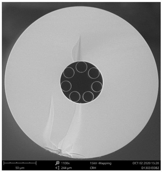
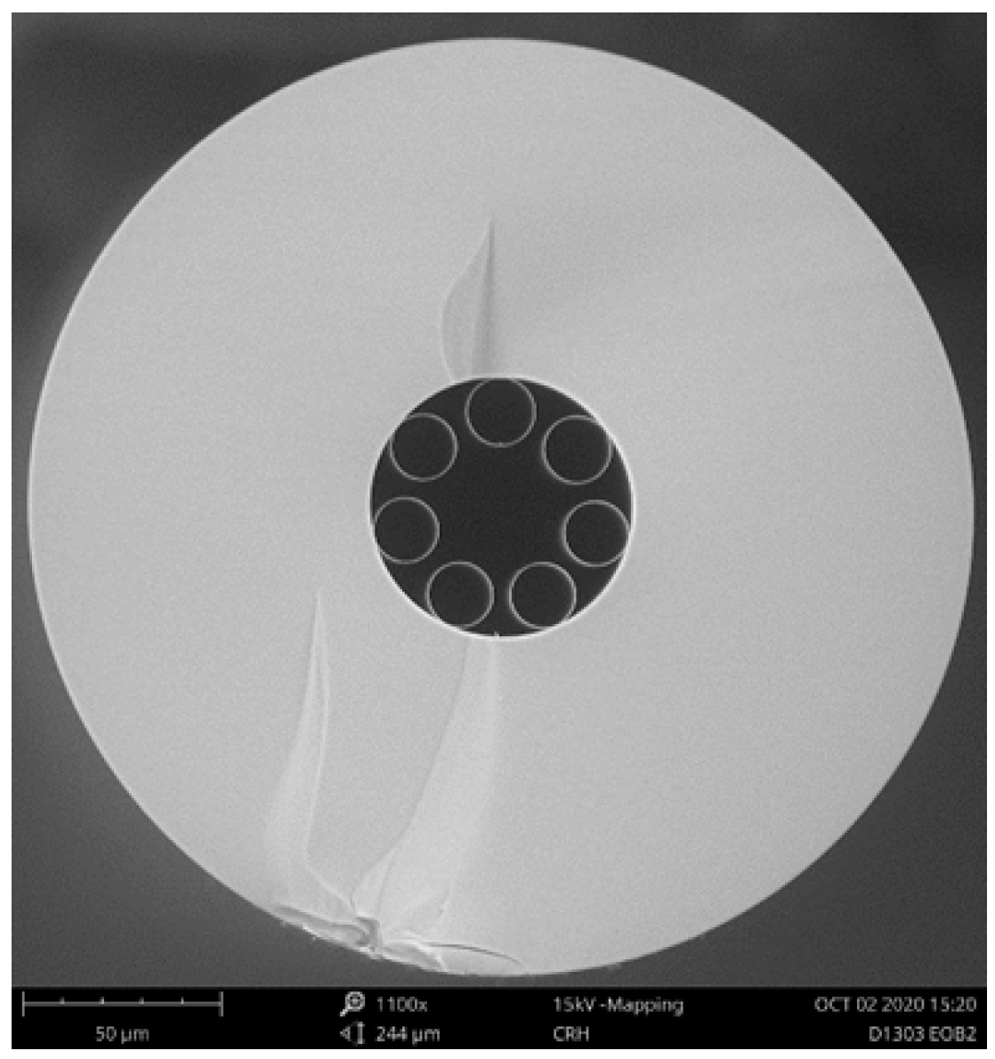
The tested AR-HCF was of a standard revolver style with 7 capillaries, fabricated from Heraeus F300 pure fused silica (manufactured by Heraeus Covantics, Kleinostheim, Germany) using the stack and draw method [46] at the University of Central Florida. It had an outer diameter of 236 µm, capillary diameter of 16.5 µm, and capillary thickness of 275 nm. Cross sectional SEM micrographs of the fiber design can be seen in Figure 1. For the irradiation test, a 15 m length of the optical fiber was used.
Figure 1.
Cross sectional SEM micrographs of the tested AR-HCF with a “revolver” design.
2.2. Optical Setup
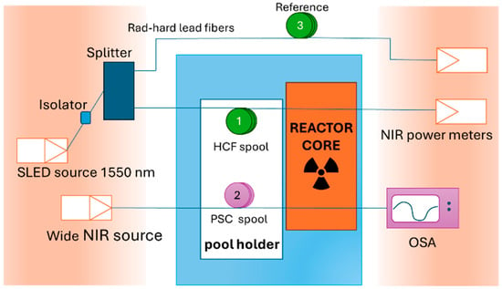
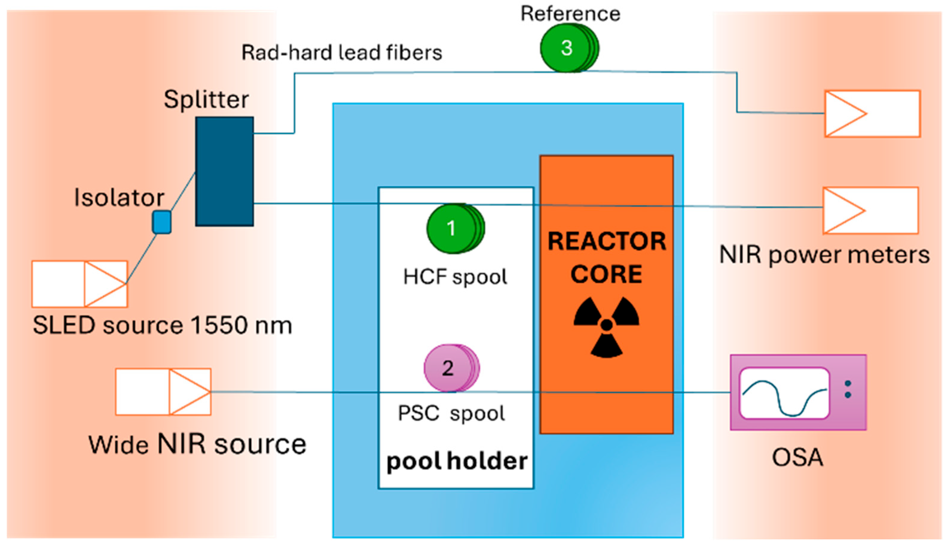
A general layout of the experimental setup can be seen in Figure 2. The HCF spool (marked 1 in the diagram), a 15 m long section of AR-HCF, was inserted into the reactor pool, and positioned by the reactor core face, in a specifically built aluminum spool and holder. The spool had a 15 cm diameter, which according to our tests introduced negligible loss at 1550 nm. The HCF was spliced to solid, pure-silica-core (PSC) fibers on both ends to lead the light in and out of the tested area. All other components and instruments were located in the reactor bay, protected from radiation, for the entirety of the measurements. The lead fibers were about 12 m long and were a single mode fiber as input (FiberCore SM1250SC manufactured by Fibercore, Southampton, UK), and multimode on the output (FG105LCA by Thorlabs, Newton, NJ, USA). Since the HCF has a large core diameter, a MM fiber was used as the collection fiber to lower the light loss in the splices. The splice losses were not negligible but were stable enough for relative transmission measurements. The light source was an SLED with a spectral width of 50 nm around the telecommunication wavelength of 1550 nm (Thorlabs SLD1005S). To measure the power during irradiation, the output fiber was connected to optical power meters (ThorLabs PM100USB with an InGaAS detector model S154C).
Figure 2.
A schematic diagram of the experimental setup.
Spool 2 was a 15 m PSC fiber (ThorLabs FG105LCA) that was part of a separate channel that ran in parallel with the HCF. This PSC fiber was used to gather attenuation data at 1550 nm and compare it with the HCF. The PSC fiber was illuminated by a different tungsten halogen light source (SLS201L), and the entire transmission spectrum was recorded using an optical spectrum analyzer (OSA). For the purposes of this measurement, only the 1550 nm data was used from the measured spectrum.
To account for any drifts in the optical components, the source was measured throughout the experiment using a conventional SMF28 fiber in a non-irradiated, stable environment (spool 3 in Figure 2).
2.3. Reactor Irradiation Conditions
The spools were irradiated at the reactor’s core face, which provided a combination of gamma radiation and neutrons. The neutron fluence and gamma dose received by the fibers are listed in Table 1. Fast neutrons have energies greater than 0.1 MeV.
Table 1.
Fiber irradiation conditions in the Breazeale Nuclear Reactor.
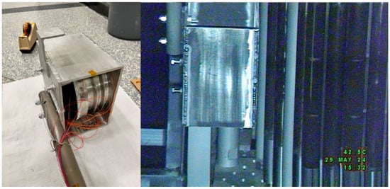
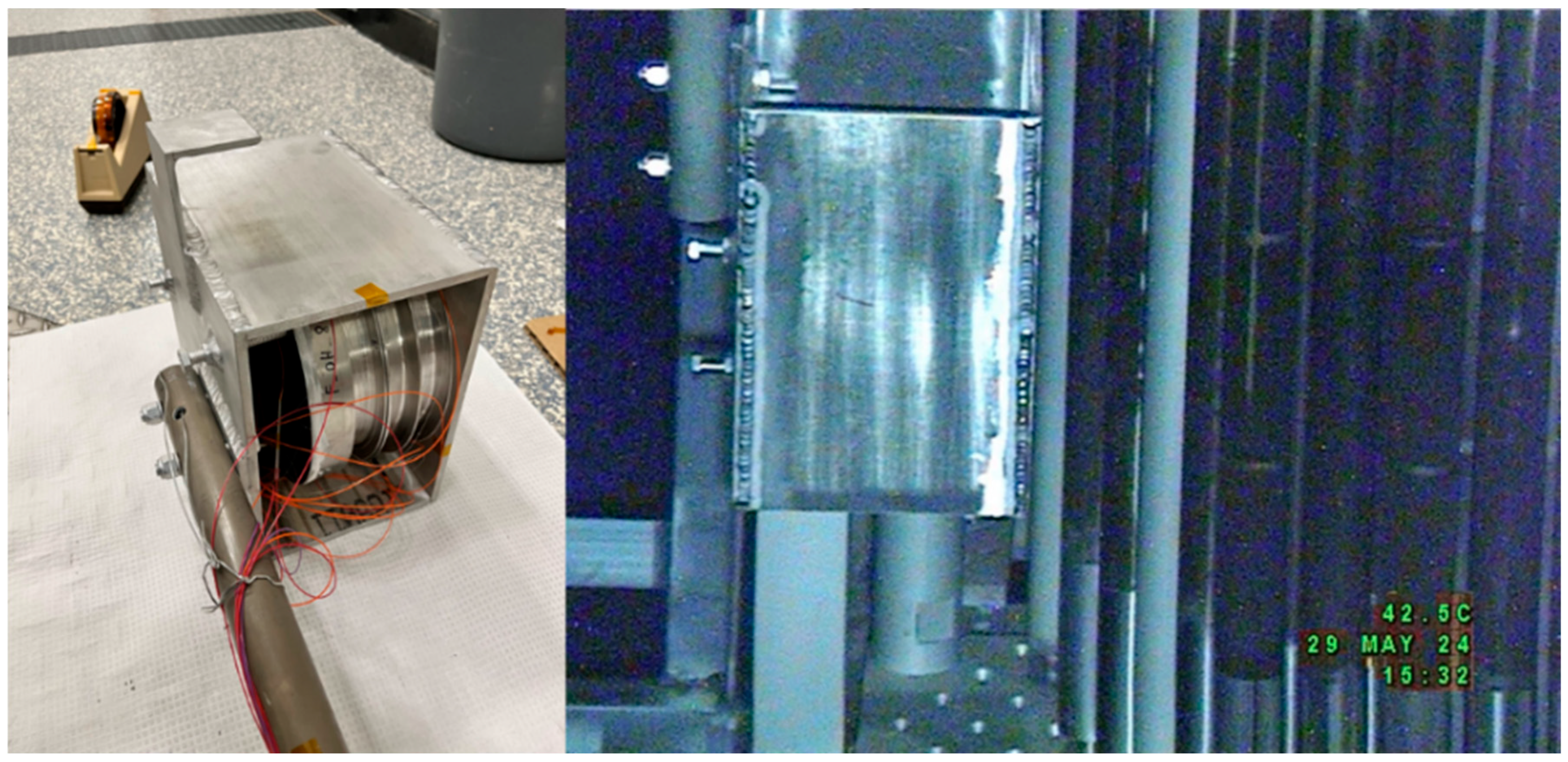
Figure 3 illustrates the fiber sample holder used to position the fiber spools at the irradiation location adjacent to the reactor core face. The holder consists of a custom-built aluminum enclosure housing aluminum spools on which the fibers to be irradiated are wound. To prevent spool movement, side-mounted bolts apply pressure against the spools, securing them firmly against the enclosure walls. As shown in the left image of Figure 3, the enclosure is attached to an aluminum pole that spans the height of the reactor pool, extending from the core centerline to above the water surface. This pole enables maneuvering of the sample holder from the bridge above the pool and allows attachment at the irradiation position via brackets that latch onto the reactor tower structure. The right image of Figure 3 shows the sample holder positioned next to the core face during irradiation; this image was captured using an underwater camera.
Figure 3.
The fiber spools in the holder before deployment (left) and inside the reactor pool by the core face (right).
3. Results
3.1. Experimental Results
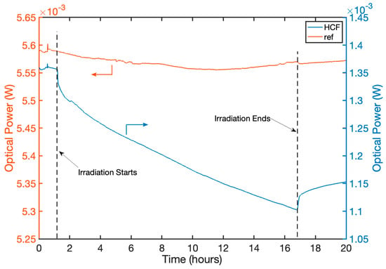
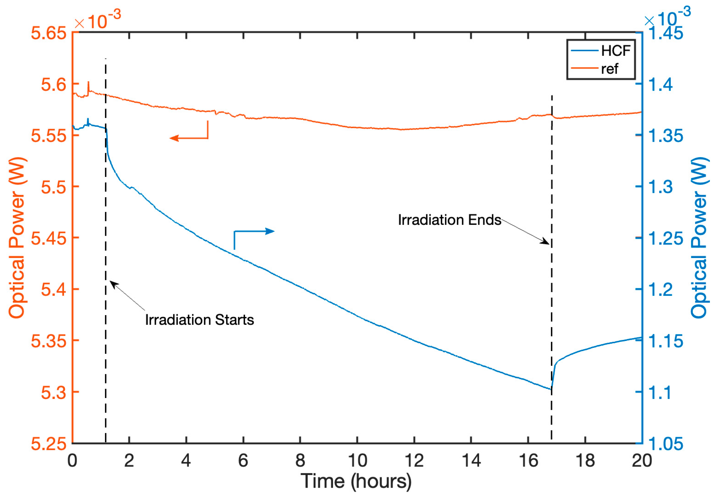
The raw power measurements of the HCF and the solid-core reference fiber are shown in Figure 4.
Figure 4.
Raw optical intensity measurements throughout the experiments. Beginning and end of reactor irradiation are noted with vertical black dashed lines.
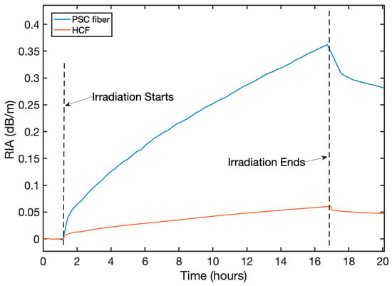
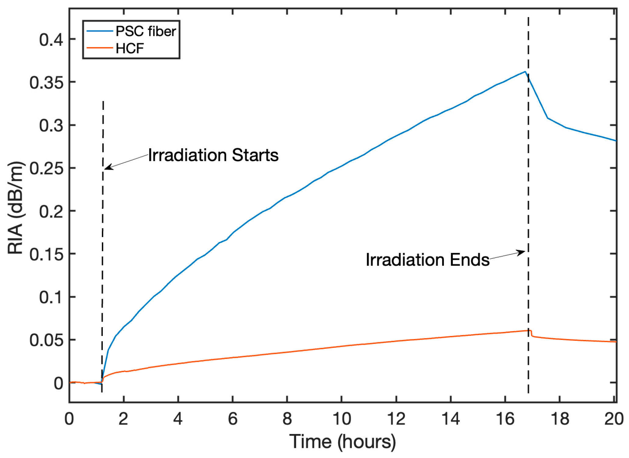
The formula described in Equation (1) was used to obtain the RIA exhibited by the fibers, expressed in dB/m. According to this definition, RIA quantifies the optical attenuation per unit length induced by ionizing radiation. The reference signal is used henceforth to correct for external intensity changes. These results can be seen in Figure 5 for the HCF fiber, in comparison to the pure-silica-core fiber that was irradiated under the same conditions. The RIA for these two fibers is monotonically increasing during reactor operation, consistent with expectations.
Figure 5.
Time evolution of RIA at 1550 nm throughout the experiment for the HCF fiber with comparison to a PSC fiber irradiated in parallel.
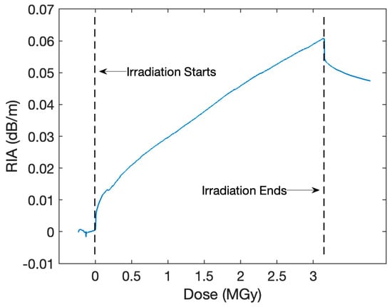
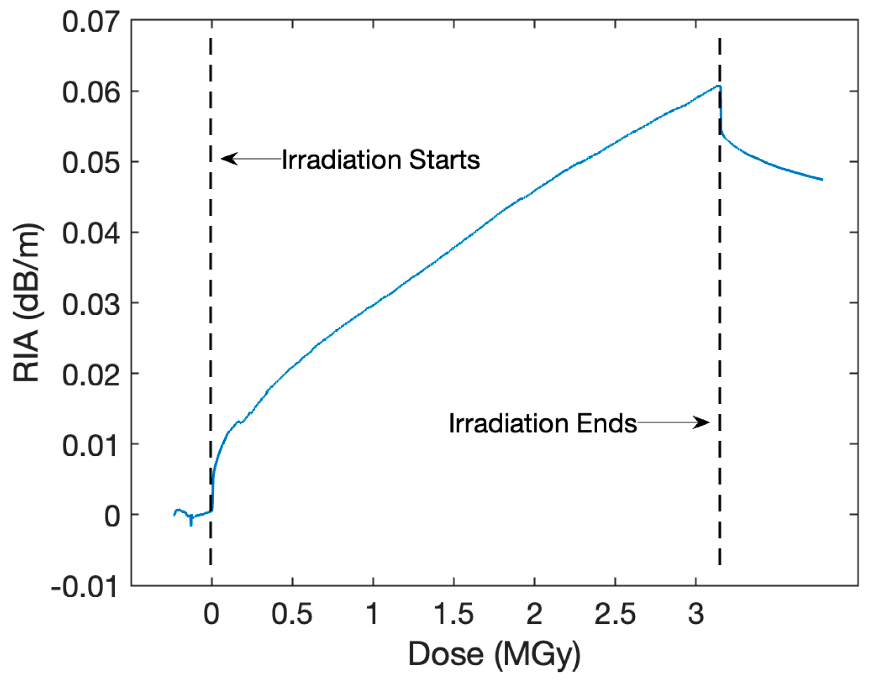
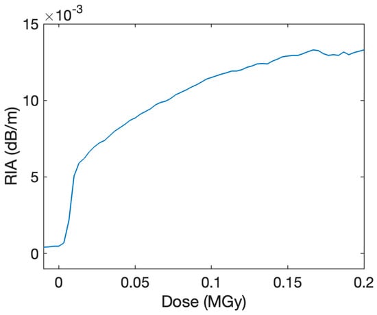
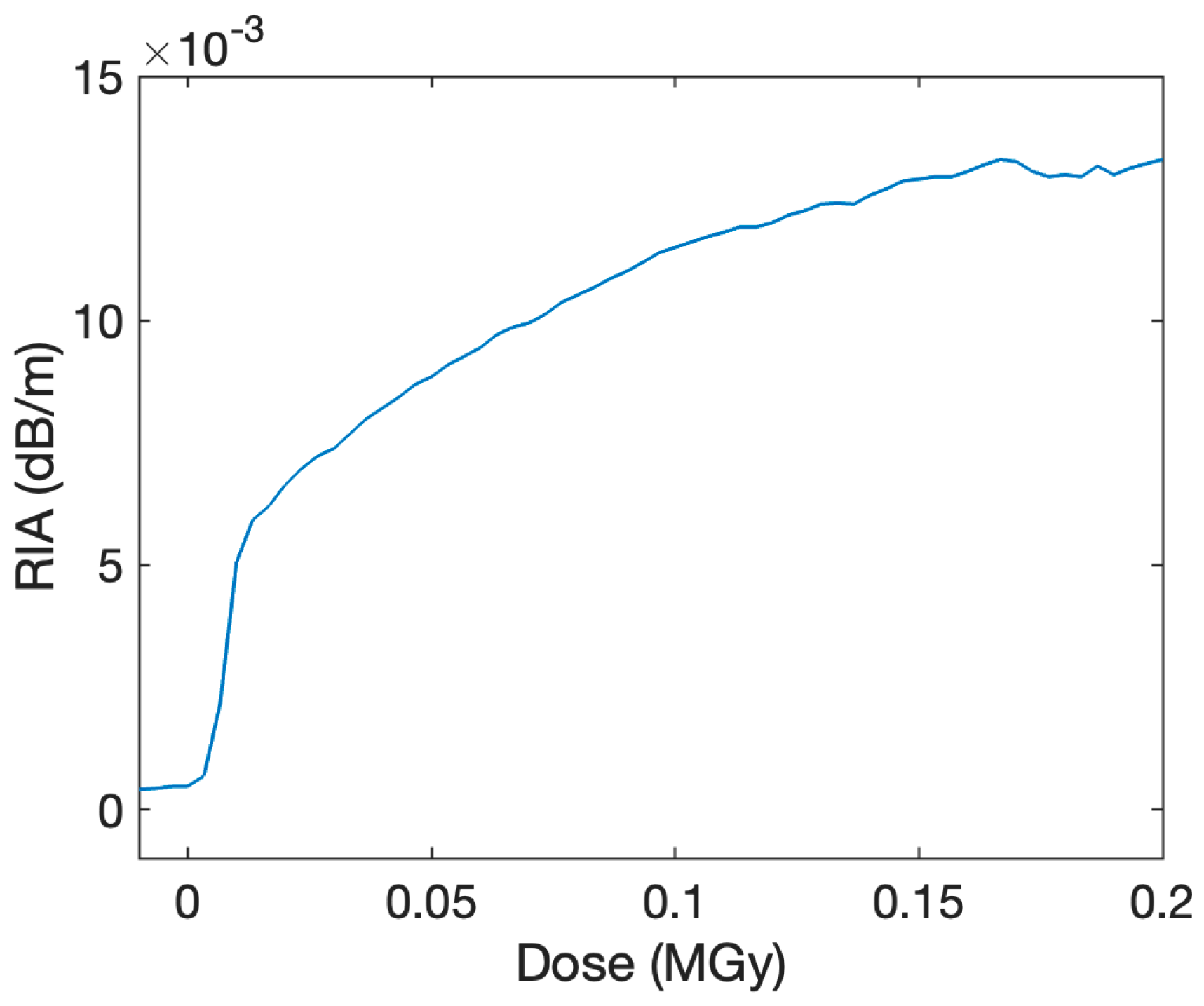
Figure 6 focuses on the RIA building up in the AR-HCF fiber. In the beginning of the irradiation (around the first 50 kGy/15 min), there is a very strong, nonlinear rise in the RIA up to around 0.01 dB/m. This initial rise is enlarged in Figure 7. After this initial stage, there is a slower, approximately linear rise in RIA of about 0.015 dB/m/MGy.
Figure 6.
RIA of HCF fiber as a function of radiation dose during the irradiation.
Figure 7.
Initial nonlinear rise in RIA of the HCF during the initial stages of reactor irradiation.
By the end of reactor irradiation, the PSC fiber attenuates light at 0.35 dB/m, while the HCF fiber exhibits an attenuation of 0.06 dB/m, after the same irradiation conditions. The PSC fiber recovers about 30% of the total RIA in about 3 h post-irradiation, whereas the HCF exhibits a very sharp recovery right around the end of irradiation, followed by a slow recovery of about 25% after 3 h.
The uncertainty associated with the optical power measurements used to calculate RIA was experimentally quantified through a dry run conducted with the same instrumentation employed in the irradiation experiments. Optical power was continuously monitored, and relative uncertainty was evaluated over successive 1 h intervals as well as over the full 5 h duration to assess temporal stability. The resulting relative errors (calculated at 3σ, corresponding to 99.7% confidence intervals) were 0.30%, 0.25%, 0.27%, and 0.31% for the first through fourth hours, respectively, and 0.35% over the full duration. This upper-bound value (0.35%) was conservatively adopted and propagated through the attenuation calculation, comprising a ratio of optical powers and base-10 logarithm, yielding an uncertainty of ±0.022 dB on optical attenuation. A second contribution arises from the fiber length measurement used to express RIA in dB/m. The fiber length was conservatively estimated to have a relative uncertainty of 1% (15 ± 0.15 m, 3σ). Combining attenuation and length uncertainties via error propagation for a ratio (RIA = A/L) yields final 3σ uncertainties of ±0.00378 dB/m for the pure-silica-core fiber (RIA = 0.35 ± 0.00378 dB/m) and ±0.00155 dB/m for the hollow-core fiber (RIA = 0.06 ± 0.00155 dB/m).
3.2. Numerical Modeling Results
Numerical modeling was performed in COMSOL Multiphysics to better understand the impact of radiation effects on the optical properties of the AR-HCF and to aid the interpretation of experimental results. Neutron radiation is known to cause compaction in fused silica, which will influence the geometry of the fiber as well as the refractive index of the silica. The optical propagation in the AR-HCF is highly dependent on both the refractive index of the silica and the geometry of the cladding elements. The AR-HCF guides light in broad transmission windows, punctuated by loss resonances. The location of these resonances is given by the following equation:
Here, λm is the resonant wavelength, t is the thickness of the capillaries, n is the refractive index of the glass, and m is the order of the resonance. Both the capillary thickness and index will change with compaction, shifting the transmission windows of the AR-HCF. Additionally, changes in the geometry and glass index will affect the mode field diameter of the propagating core mode, as well as the confinement of the mode within the air core. As the effects of compaction on the optical properties of the AR-HCF could be contributing to the measured RIA, they were each investigated in the simulation. Compaction saturates about 3% for fused silica at high radiation doses. This correlates to a 3% decrease in volume and an approximate 1% increase in refractive index [47].
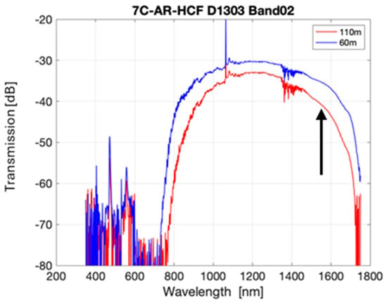
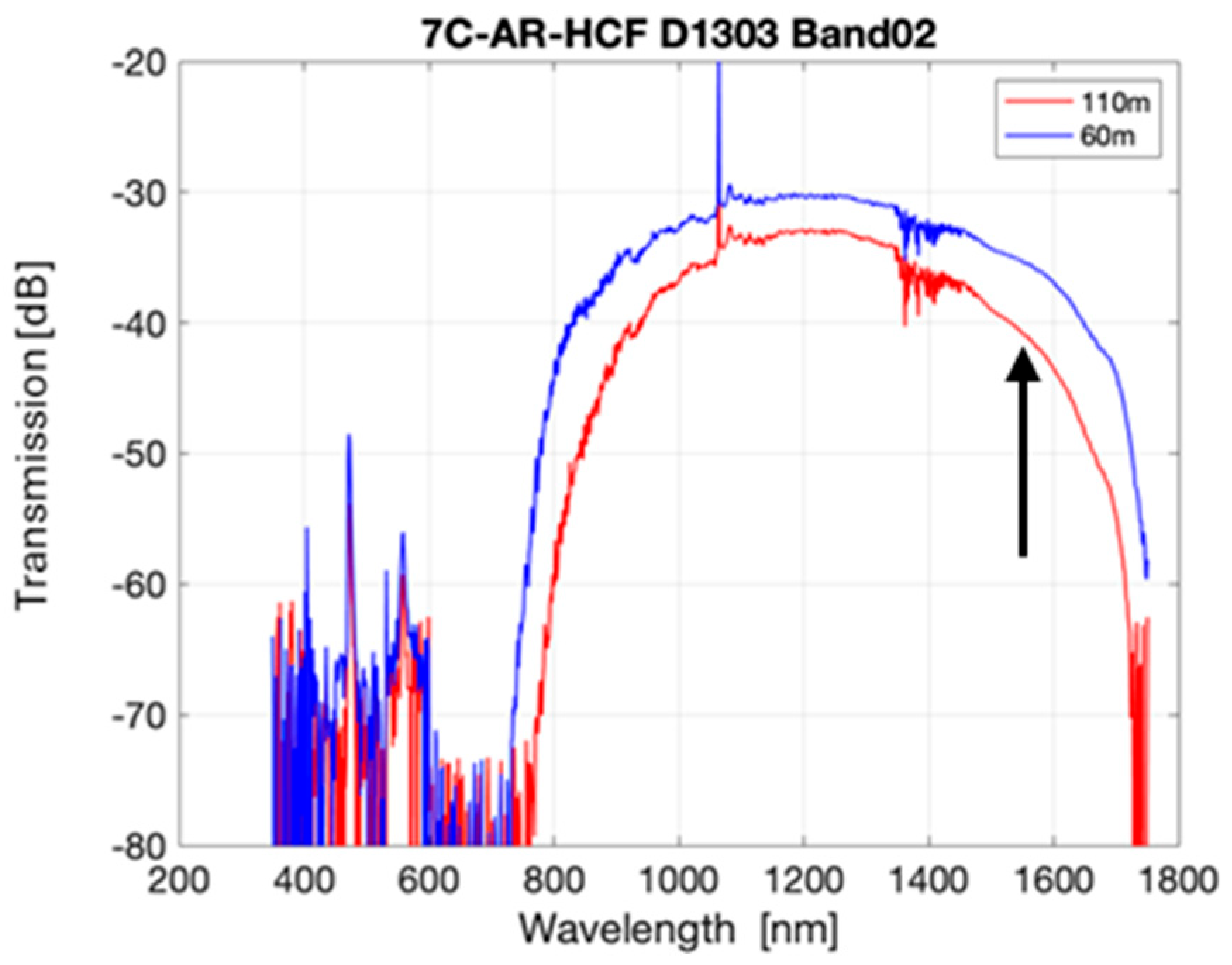
The first theoretical investigation looked at the change in the transmission of the AR-HCF due to compaction with respect to wavelength. As the above equation shows, changes in capillary thickness and refractive index will shift the wavelengths of the loss resonances. The measured transmission spectrum of the AR-HCF tested is shown in Figure 8. The center of the transmission window is around 1060 nm, but due to limited resources at the time of the test, this fiber was tested only at 1550 nm. Because 1550 nm is on the edge of the transmission window, any shift in the resonance wavelength will cause a change in the loss at 1550 nm. It is worth noting, however, that this effect would be even weaker or completely absent if the HCF structure was optimized for its expected operating wavelength (e.g., 1550 nm) since the transmission wavelength would be further away from resonances. In such a case, potential radiation-induced resonance shifts would not lead to any appreciable change in attenuation.
Figure 8.
AR-HCF transmission spectrum, with wavelength used for RIA measurement indicated by a black vertical arrow.
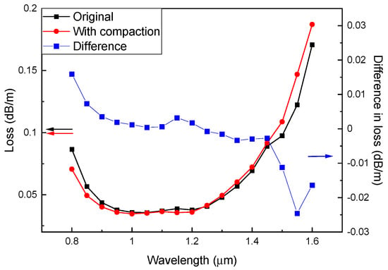
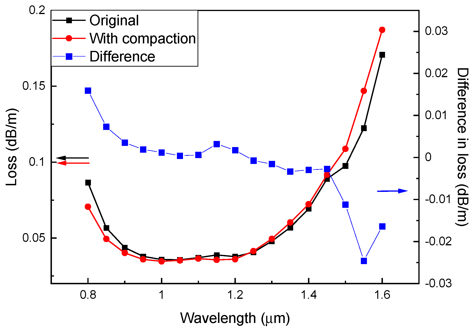
COMSOL Multiphysics was used to calculate the loss vs. wavelength for the tested AR-HCF. The loss spectrum was then compared between the original fiber parameters and those after compaction. Figure 9 shows the slight spectral shift towards longer wavelengths with compaction. From the above equation, the decrease in capillary thickness would cause the loss resonances to shift to short wavelengths, while the increase in refractive index would cause it to shift to longer wavelengths. These counter-acting effects caused by compaction led to a minimal change in loss at 1550 nm. The calculated propagation loss only increased from 0.144 dB/m to 0.147 dB/m (a change of about 0.003 dB/m). Due to the opposing shifts caused by the silica densification, the change in loss caused by the resonance shift is significantly less than the measured 0.06 dB/m RIA, and therefore is most likely not the primary cause.
Figure 9.
Simulated loss spectrum of AR-HCF after expected compaction.
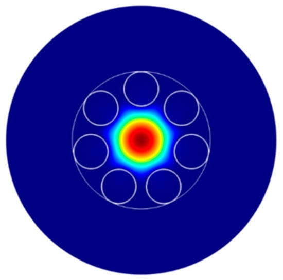
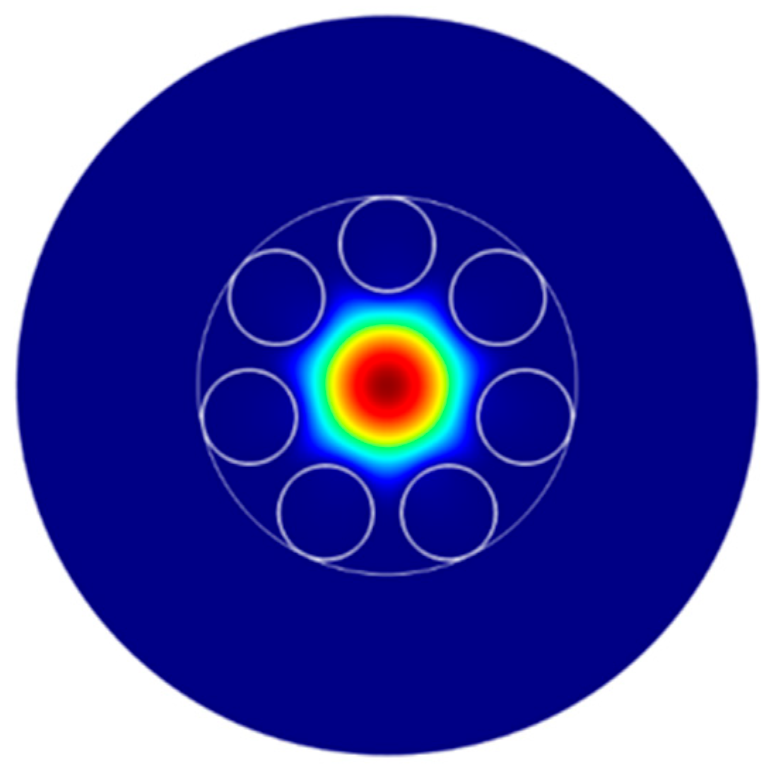
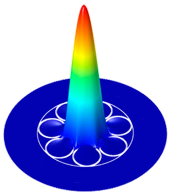
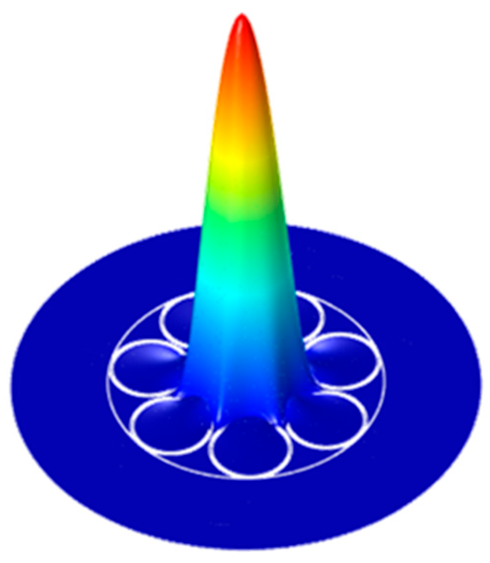
Another key property of the optical fiber that will be affected by compaction is the mode field diameter (MFD) of the fundamental core mode. The fundamental mode of the AR-HCF is mostly Gaussian, as shown in Figure 10 below. The MFD of both the solid-core PSC Fiber and the AR-HCF will change with a change in index and fiber geometry. Using COMSOL Multiphysics, the MFD was calculated for the AR-HCF and for the PSC-SMF both with and without compaction. For the PSC Fiber, the MFD decreased from 7.57 µm to 7.50 µm with compaction at 1550 nm. Similarly, the MFD of the AR-HCF decreased from 23.53 µm to 23.32 µm with compaction.
Figure 10.
The fundamental mode of the AR-HCF.
Another potential cause of the measured RIA is the change in coupling between the PSC-SMF fiber and the AR-HCF. As both MFDs change with compaction, the coupling efficiency between the two fibers at the splice will also change. The coupling efficiency was calculated based on the above MFDs and the following equations:
Here is the ratio of fiber MFDs and η is the coupling efficiency. With compaction, the coupling efficiency did not change by a measurable amount. Based on this analysis, the change in coupling efficiency is not a reasonable source of the measured RIA.
A third theoretical investigation focused on the overlap of the light in the AR-HCF with the fused silica of the fiber. Typically, the light in the AR-HCF is heavily confined to the air core, with very little overlap with the silica fiber structure, as shown in Figure 11. Therefore, the radiation-induced damage occurring in the silica has a significantly reduced impact on the optical propagation in a hollow-core fiber. This is the primary reason for the reduced RIA when compared to a solid glass fiber.
Figure 11.
The guided light’s field intensity in the AR-HCF cross sectional structure.
It may be expected that the level of reduction in RIA would be correlated to the amount of overlap of the propagating light with the glass. The optical power overlapping with the silica structure of the AR-HCF was calculated using COMSOL and was found to be only a fraction of 4.6 × 10⁻⁵ from the total power around 1550 nm. It is evident that the measured RIA is not directly correlated to the level of optical confinement in the hollow core, as the calculated confinement is orders of magnitude higher than the measured RIA progression. To put it more clearly, if the HCF’s RIA effect was caused by silica defects, the level of the attenuation would have been the fraction of the overlap from the effect as seen in the PSC fiber (where the RIA is caused by silica defects). This would have produced an RIA ratio of five orders of magnitude between the two fibers, but the ratio is less than one (see Figure 5).
Another theory we explored was the silica compaction causing a change in the confinement of the core light, potentially leading to RIA. The overlap was recalculated with 3% compaction, changing both the fiber geometry and refractive index of the silica, and the value was slightly reduced to 4.5 × 10⁻⁵, thus ruling out core confinement as a potential cause of the measured RIA.
The theoretical investigations performed in COMSOL did not identify the source of the measured RIA, but they did eliminate several potential causes. The shift in the loss resonance, change in coupling efficiency between the input fiber and the AR-HCF, and the change in light confinement within the hollow core all proved to not be the source of the measured loss. While silica compaction clearly impacts light guidance in the AR-HCF, the decrease in volume and increase in index appear to mostly counteract each other, leading to small overall effects.
4. Discussion
The AR-HCF and the solid-core PSC exhibited the well-known monotonic RIA response to irradiation. This in itself indicates that the measurements were valid throughout the irradiation, without showing signs of instabilities. At the end of the irradiation, the HCF fiber RIA is a factor of six lower than that of the PSC fiber, when compared in terms of dB/m. This is a significant reduction in RIA since it is compared to the solid-core fiber chemistry with the best radiation tolerance and thus holds significant promise for deployment of HCFs in high-radiation environments.
In the modeling section, we explained how we ruled out the possibility that the attenuation might arise from structural changes caused by the compaction of the silica under the neutron flux. Saturated compaction parameters were intentionally adopted to represent a worst-case scenario, corresponding to the maximum reported density change in silica. Any partial saturation at the investigated dose levels would result in a smaller refractive index change and therefore a reduced impact on attenuation. Likewise, potential non-uniform compaction along the fiber length would further decrease the effective compaction when integrated over the irradiated section, reinforcing the conclusion that compaction cannot account for the observed attenuation. Another possibility is that the evanescent field of light that travels within the silica is affected by the radiation damage of silica, analogously to that of the PSC fiber. However, the amount of energy that interfaces with the silica is quite small (a fraction of 4.6 × 10⁻⁵ from the total), so a much smaller effect is expected relative to the PSC fiber. Because of what we know about the mode field’s overlap with silica, and all the effects that were simulated, we would expect a lower RIA than what we measured with the AR-HCF.
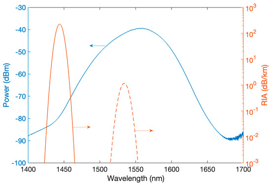
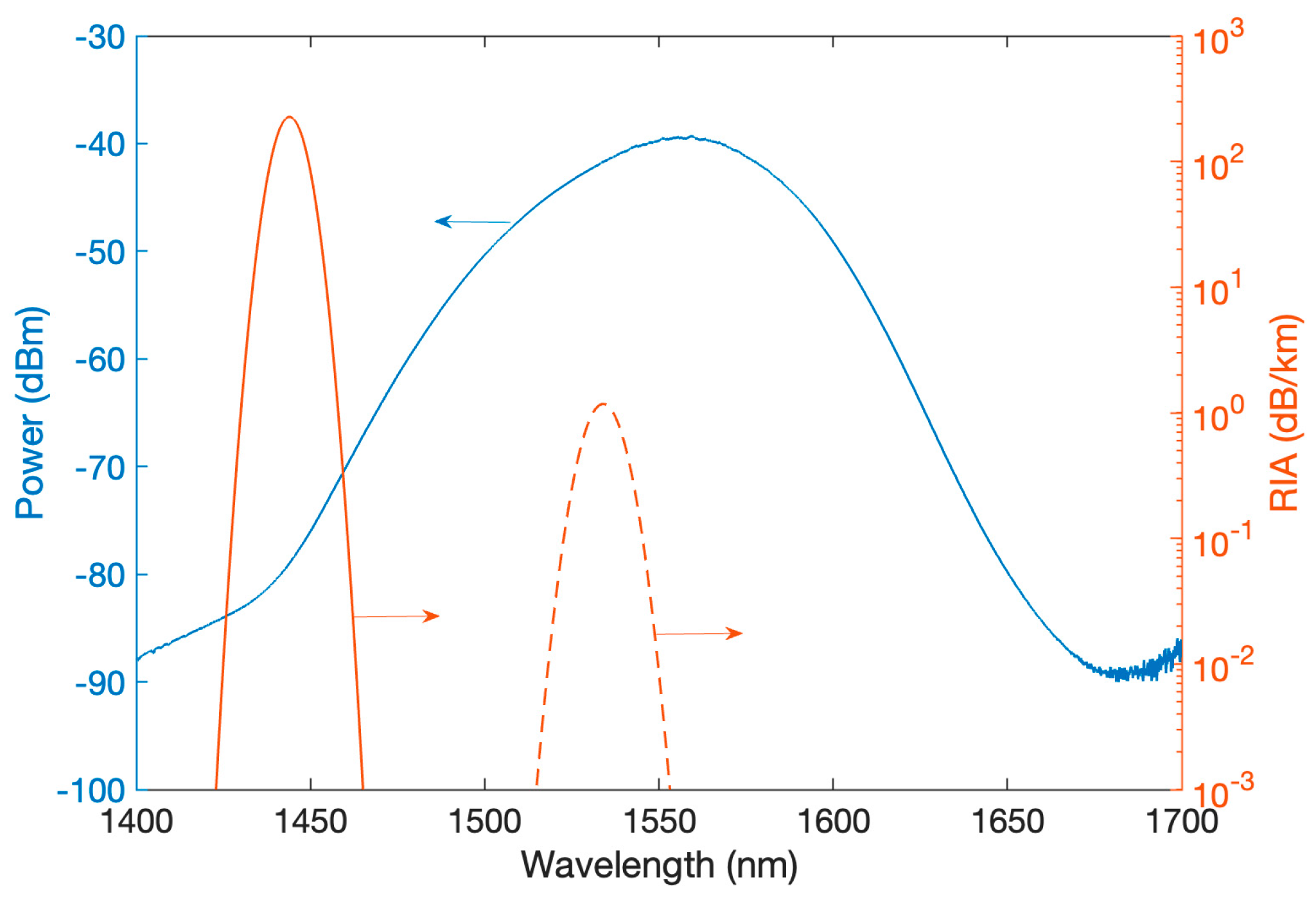
The last effect we considered is a change in the gas that fills the hollow core. We note that the hollow core of our AR-HCF fiber is filled with air, which naturally contains a certain amount of humidity. A known effect that takes place when air is exposed to ionization radiation is the production of nitric acid (HNO3). This phenomenon was observed by Medaer et al. [45], measuring HCFs that were irradiated with X-ray up to 240 kGy. In that work, clear absorption lines centered around 1444 nm and 1534 nm were measured (among others that occurred outside of the spectral region used in our study). These lines grew stronger, approximately in a linear fashion, causing RIA-equivalent attenuation of up to ~140 dB/km at around 1444 nm and ~1.5 dB/km at around 1534 nm. The light source that was used in our work was centered about 1550 nm and spanned from 1425 to 1675 nm, with a 50 dB difference from the peak to the edges, in a roughly bell curve distribution, as shown in Figure 12. By linearly extrapolating the rising attenuation caused by the generated nitric acid to the total dose that was reached in our experiment, we obtain about 0.02 dB/m at 1534 nm, which is where the main overlap with our source lies. This is about a third of the attenuation measured in our experiment, i.e., the same order of magnitude as the RIA reached under our conditions. Considering that the rise in the concentration of the absorber is not necessarily linear and considering that the levels of the initial humidity in the HCF might be radically different between our experiment and that of Medaer et al., this phenomenon might be the cause of the attenuation. In addition, the measurements by Medaer et al. were carried out under X-ray, which is different than the radiation field used in our experiments, comprising higher-energy gamma and neutrons. The radiolytic production of nitric acid may be higher in our radiation field, leading to an underestimation of the attenuation when extrapolating from the attenuation numbers measured in X-ray by Medaer et al. Another support to this claim is the relatively low recovery in the AR-HCF RIA after reactor shutdown. There is a sudden drop right after the shutdown that can be attributed to the minor contribution due to the short-lived defects generated in the silica. The un-recovered RIA is likely due to the HNO3 absorption. After its radiolytic generation, nitric acid is relatively stable inside the glass vessel of the HCF, as long as it is not exposed to strong sunlight or heat [48], neither of which were present post-irradiation. Chemistry and kinetics related to the formation and possibly the destruction of HNO3 can provide more insight into the individual contributions of these effects to the overall RIA during irradiation.
Figure 12.
The power distribution of the SLED light source as measured by an optical spectrum analyzer (left axis) along with the absorbing lines of nitric acid after 240 kGy of irradiation (right axis), as adapted from Medaer et al. [45].
This localized absorption peak can be avoided by using narrow light sources in other regions of the spectrum, which subjects the fiber to a much smaller, almost negligible RIA, even under higher doses. Another strategy is to control the atmosphere inside the hollow core of the HCF, for example by filling it with argon or nitrogen gas, which also enables a range of spectroscopic measurements. By carefully calibrating the radiolytic reaction rates that generate detectable compounds, this approach could support a new form of distributed dosimetry. Because gas diffusion in these small cylindrical cores is very slow, it may be possible to probe spatial variations in the spectra using a pulsed laser and to exploit nonlinear scattering effects. This would enable Raman spectroscopy of irradiated gases over long cells, localized to spatially dependent radiation levels, providing a path to a distributed dosimeter.
The next step to validate the hypothesis that the RIA in the HCF was caused by the formation of nitric acid is to conduct an absorption spectroscopy experiment with a more spectrally encompassing measurement and to compare an air-filled HCF with the same fiber filled with argon or nitrogen.
5. Conclusions
This study measured the near-infrared (NIR) radiation-induced attenuation (RIA) of an anti-resonant hollow-core optical fiber (AR-HCF) irradiated with neutrons and gamma radiation in a nuclear reactor. The results are compared to the RIA experienced by a pure-silica, solid-core fiber irradiated in the same environment. The AR-HCF exhibited a NIR RIA that is about six times lower than the pure-silica, solid-core fiber, showing excellent promise for data transmission and sensing in high-radiation applications such as fission and fusion reactors and particle accelerators. We show that the magnitude of the RIA in this particular spectral region is consistent with a previously reported radiolytic reaction that produces nitric acid, which exhibits absorption at these wavelengths. Lastly, we indicated a path to further increase radiation tolerance and develop sensing approaches based on this highly radiation-resilient optical waveguide.
Author Contributions
Conceptualization, F.S.; Data curation, S.Z., A.V.N., M.L. and M.C.; Formal analysis, A.V.N. and F.S.; Funding acquisition, F.S.; Investigation, W.L., M.L., M.C., M.R. and F.S.; Methodology, S.Z., W.L., D.B., J.A.G., A.S., M.R. and F.S.; Project administration, F.S.; Resources, A.V.N., J.A.G., E.A.L., R.A.C., A.S., M.R. and F.S.; Software, A.V.N.; Supervision, F.S.; Validation, D.B. and J.A.G.; Writing—original draft, S.Z.; Writing—review and editing, A.V.N., W.L., M.L., M.C. and F.S. All authors have read and agreed to the published version of the manuscript.
Funding
This research was supported in part by the Army Research Office (W911NF1910426) and the Department of the Navy (N68335-20-395-C0862).
Data Availability Statement
Data will be made available upon reasonable request.
Conflicts of Interest
The authors declare no conflicts of interest.
Abbreviations
The following abbreviations are used in this manuscript:
| HCF | Hollow-Core Fiber |
| RIA | Radiation-Induced Attenuation |
| NIR | Near-Infrared |
| AR-HCF | Anti-Resonant Hollow-Core Fiber |
| PSC | Pure-Silica Core |
References
- Borzycki, K.; Osuch, T. Hollow-Core Optical Fibers for Telecommunications and Data Transmission. Appl. Sci. 2023, 13, 10699. [Google Scholar] [CrossRef] [Scilit]
- Debord, B.; Amrani, F.; Vincetti, L.; Gérôme, F.; Benabid, F. Hollow-core fiber technology: The rising of ‘gas photonics’. Fibers 2019, 7, 16. [Google Scholar] [CrossRef] [Scilit]
- Gao, S.; Wang, Y.; Liu, X.; Hong, C.; Gu, S.; Wang, P. Nodeless hollow-core fiber for the visible spectral range. Opt. Lett. 2016, 42, 61–64. [Google Scholar] [CrossRef] [Scilit]
- Foroni, M.; Passaro, D.; Poli, F.; Cucinotta, A.; Selleri, S.; Lægsgaard, J.; Bjarklev, A.O. Guiding properties of silica/air hollow-core Bragg fibers. J. Light. Technol. 2008, 26, 1877–1884. [Google Scholar] [CrossRef] [Scilit]
- Poletti, F.; Petrovich, M.N.; Richardson, D.J. Hollow-core photonic bandgap fibers: Technology and applications. Nanophotonics 2013, 2, 315–340. [Google Scholar] [CrossRef] [Scilit]
- Benabid, F. Hollow-core photonic bandgap fibre: New light guidance for new science and technology. Philos. Trans. R. Soc. A Math. Phys. Eng. Sci. 2006, 364, 3439–3462. [Google Scholar] [CrossRef] [Scilit]
- Yu, F.; Knight, J.C. Negative Curvature Hollow-Core Optical Fiber. IEEE J. Sel. Top. Quantum Electron. 2016, 22, 146–155. [Google Scholar] [CrossRef] [Scilit]
- Ding, W.; Wang, Y.-Y.; Gao, S.-F.; Wang, M.-L.; Wang, P. Recent progress in low-loss hollow-core anti-resonant fibers and their applications. IEEE J. Sel. Top. Quantum Electron. 2019, 26, 1–12. [Google Scholar] [CrossRef] [Scilit]
- Ni, W.; Yang, C.; Luo, Y.; Xia, R.; Lu, P.; Hu, D.J.J.; Danto, S.; Shum, P.P.; Wei, L. Recent Advancement of Anti-Resonant Hollow-Core Fibers for Sensing Applications. Photonics 2021, 8, 128. [Google Scholar] [CrossRef] [Scilit]
- Jaworski, P. A review of antiresonant hollow-core fiber-assisted spectroscopy of gases. Sensors 2021, 21, 5640. [Google Scholar] [CrossRef] [Scilit]
- Udd, E.; Spillman, W.B. Fiber Optic Sensors: An Introduction for Engineers and Scientists; John Wiley & Sons Inc.: Hoboken, NJ, USA, 1990. [Google Scholar]
- Kok, S.P.; Go, Y.L.; Wang, X.; Wong, M.L.D. Advances in Fibre Bragg Grating (FBG) Sensing: A Review of Conventional and New Approaches and Novel Sensing Materials in Harsh and Emerging Industrial Sensing. IEEE Sens. J. 2024, 24, 29485–29505. [Google Scholar] [CrossRef] [Scilit]
- Sahota, J.K.; Gupta, N.; Dhawan, D. Fiber Bragg grating sensors for monitoring of physical parameters: A comprehensive review. Opt. Eng. 2020, 59, 060901. [Google Scholar] [CrossRef] [Scilit]
- Thévenaz, L. Review and Progress in Distributed Fiber Sensing. In Optical Fiber Sensors; Optica Publishing Group: Washington, DC, USA, 2006; p. ThC1. [Google Scholar] [CrossRef] [Scilit]
- Lo, W.; Scurti, F. Rayleigh-backscattering Interrogated Optical Fibers in HTS coils: Effects of AC Currents on Optical Fiber signals. Supercond. Sci. Technol. 2025, 38, 125030. [Google Scholar] [CrossRef] [Scilit]
- Lu, P.; Lalam, N.; Badar, M.; Liu, B.; Chorpening, B.T.; Buric, M.P.; Ohodnicki, P.R. Distributed optical fiber sensing: Review and perspective. Appl. Phys. Rev. 2019, 6, 041302. [Google Scholar] [CrossRef] [Scilit]
- Scurti, F.; Ishmael, S.; Flanagan, G.; Schwartz, J. Quench detection for high temperature superconductor magnets: A novel technique based on Rayleigh-backscattering interrogated optical fibers. Supercond. Sci. Technol. 2016, 29, 03LT01. [Google Scholar] [CrossRef] [Scilit]
- Rovera, A.; Tancau, A.; Boetti, N.; Dalla Vedova, M.D.L.; Maggiore, P.; Janner, D. Fiber Optic Sensors for Harsh and High Radiation Environments in Aerospace Applications. Sensors 2023, 23, 2512. [Google Scholar] [CrossRef] [Scilit]
- Rountree, S.D.; Ohanian, O.J.; Boulanger, A.J.; Kominsky, D.; Davis, M.; Wang, M.; Chen, K.P.; Leong, A.; Zhang, J.D.; Scurti, F.D.; et al. Multi-parameter fiber optic sensing for harsh nuclear environments. In Fiber Optic Sensors and Applications XVII; Society of Photographic Instrumentation Engineers: Washington, DC, USA, 2021; p. 16. [Google Scholar] [CrossRef] [Scilit]
- Zilberman, S.; Berkovic, G.; London, Y.; Dadon, M.; Shafir, E.; Ozeri, O.; Ben-Meir, K.; Krakovich, A.; Makmal, T. Response of Differently Inscribed Fiber Bragg Gratings to Very High Doses of Ionizing Radiation. In Proceedings of the European Workshop on Optical Fibre Sensors (EWOFS 2023), Mons, Belgium, 23–26 May 2023; SPIE 12643, 126433H. [Google Scholar] [CrossRef] [Scilit]
- Leoschke, M.; Zilberman, S.; Lo, W.; Catellani, M.; Beck, D.; Geuther, J.; Scurti, F. Simultaneous measurement of temperature and ionizing radiation dose based on type-II FBGs inscribed in P-doped optical fibers. In Proceedings of the 29th International Conference on Optical Fiber Sensors; Lopez-Amo Sainz, M., Santos, J.L., Sun, T., Eds.; Society of Photographic Instrumentation Engineers: Washington, DC, USA, 2025; p. 521. [Google Scholar] [CrossRef] [Scilit]
- Liu, D.; Wu, Q.; Mei, C.; Yuan, J.; Xin, X.; Mallik, A.K.; Wei, F.; Han, W.; Kumar, R.; Yu, C. Hollow Core Fiber Based Interferometer for High-Temperature (1000 °C) Measurement. J. Light. Technol. 2018, 36, 1583–1590. Available online: https://opg.optica.org/jlt/abstract.cfm?URI=jlt-36-9-1583 (accessed on 9 February 2026). [CrossRef] [Scilit]
- Balbier, C.; Bucks, S.; Scurti, F.; Lee, S. High-Temperature Fiber Optic Sensor Performance for Heat Pipe Instrumentation. IEEE Sens. J. 2025, 25, 17117–17127. [Google Scholar] [CrossRef] [Scilit]
- Scurti, F.; Velez, C.; Kelly, A.; Ishmael, S.; Schwartz, J. In-field strain and temperature measurements in a (RE)Ba2Cu3O7−x coil via Rayleigh-backscattering interrogated optical fibers. Smart Mater. Struct. 2023, 32, 065006. [Google Scholar] [CrossRef] [Scilit]
- He, Z.; Liu, Q. Optical Fiber Distributed Acoustic Sensors: A Review. J. Light. Technol. 2021, 39, 3671–3686. [Google Scholar] [CrossRef] [Scilit]
- Ohodnicki, P.R.; Sarcinelli, E.; Zhang, P.; Naeem, K.; Karki, D.; Meyer, R.; Lalam, N.; Wright, R. Nuclear canister integrity monitoring using quasi-distributed fiber acoustic sensors and physics-based modeling. In Optical Waveguide and Laser Sensors II; Sanders, G.A., Lieberman, R.A., Udd Scheel, I., Eds.; Society of Photographic Instrumentation Engineers: Washington, DC, USA, 2023; p. 17. [Google Scholar] [CrossRef] [Scilit]
- Zur, A.; Katzir, A. Theory of fiber optic radiometry, emissivity of fibers, and distributed thermal sensors. Appl. Opt. 1991, 30, 660–673. [Google Scholar] [CrossRef] [Scilit]
- Scharf, V.; Katzir, A. Four-band fiber-optic radiometry for determining the ‘true’ temperature of gray bodies. Appl. Phys. Lett. 2000, 77, 2955–2957. [Google Scholar] [CrossRef] [Scilit]
- Agoyan, M.; Fourneau, G.; Cheymol, G.; Ladaci, A.; Maskrot, H.; Destouches, C.; Fourmentel, D.; Gérand, S.; Gaillard-Groléas, J.; Desjacques, M.; et al. Confocal chromatic sensor for displacement monitoring in research reactor. EPJ Web. Conf. 2021, 253, 04021. [Google Scholar] [CrossRef] [Scilit]
- Cheymol, G.; Verneuil, A.; Grange, P.; Maskrot, H.; Destouches, C. High-Temperature Measurements with a Fabry–Perot Extensometer. IEEE Trans. Nucl. Sci. 2020, 67, 552–558. [Google Scholar] [CrossRef] [Scilit]
- Berkovic, G.; Shafir, E. Optical methods for distance and displacement measurements. Adv. Opt. Photon. 2012, 4, 441–471. [Google Scholar] [CrossRef] [Scilit]
- Ding, H.; Hu, D.J.J.; Yu, X.; Liu, X.; Zhu, Y.; Wang, G. Review on All-Fiber Online Raman Sensor with Hollow Core Microstructured Optical Fiber. Photonics 2022, 9, 134. [Google Scholar] [CrossRef] [Scilit]
- Nie, Q.; Liu, Z.; Cheng, M.; Pei, S.; Yang, D.; Guo, D.; Yang, M. Review on hollow-core fiber based multi-gas sensing using Raman spectroscopy. Photonic Sens. 2024, 14, 240412. [Google Scholar] [CrossRef] [Scilit]
- Nissen, M.; Doherty, B.; Hamperl, J.; Kobelke, J.; Weber, K.; Henkel, T.; Schmidt, M.A. UV absorption spectroscopy in water-filled antiresonant hollow core fibers for pharmaceutical detection. Sensors 2018, 18, 478. [Google Scholar] [CrossRef] [Scilit] [PubMed]
- Dufour, A.; Morana, A.; Meyer, A.; Marin, E.; Boukenter, A.; Ouerdane, Y.; Girard, S. Overview of the Infrared Radiation Responses of Telecom-Grade Single Mode Optical Fibers. J. Light. Technol. 2024, 42, 4987–4996. [Google Scholar] [CrossRef] [Scilit]
- Girard, S.; Kuhnhenn, J.; Gusarov, A.; Brichard, B.; Van Uffelen, M.; Ouerdane, Y.; Boukenter, A.; Marcandella, C. Radiation effects on silica-based optical fibers: Recent advances and future challenges. IEEE Trans. Nucl. Sci. 2013, 60, 2015–2036. [Google Scholar] [CrossRef] [Scilit]
- Girard, S.; Kuhnhenn, J.; Gusarov, A.; Morana, A.; Paillet, P.; Robin, T.; Weninger, L.; Fricano, F.; Roche, M.; Campanella, C.; et al. Overview of Radiation Effects on Silica-Based Optical Fibers and Fiber Sensors. IEEE Trans. Nucl. Sci. 2024, 72, 982–1020. [Google Scholar] [CrossRef] [Scilit]
- Zilberman, S.; Lo, W.; Guzman, K.N.H.; Van Horn, Z.; Dror, R.; Bruner, A.; Scurti, F.; Harrera, K. Near infrared radiation induced attenuation in P-doped and Al-doped optical fibers at cryogenic temperature. Opt. Contin. 2025, 4, 1411. [Google Scholar] [CrossRef] [Scilit]
- Morana, A.; Campanella, C.; Vidalot, J.; De Michele, V.; Marin, E.; Reghioua, I.; Boukenter, A.; Ouerdane, Y.; Paillet, P.; Girard, S. Extreme radiation sensitivity of ultra-low loss pure-silica-core optical fibers at low dose levels and infrared wavelengths. Sensors 2020, 20, 7254. [Google Scholar] [CrossRef] [Scilit]
- Weninger, L.; Morana, A.; Campanella, C.; Vidalot, J.; Marin, E.; Ouerdane, Y.; Boukenter, A.; Alía, R.G.; Girard, S. Radiation monitoring with radiosensitive pure-silica core ultralow loss optical fiber. IEEE Trans. Nucl. Sci. 2024, 71, 1813–1820. [Google Scholar] [CrossRef] [Scilit]
- Cheymol, G.; Long, H.; Villard, J.F.; Brichard, B. High level gamma and neutron irradiation of silica optical fibers in CEA OSIRIS nuclear reactor. In Proceedings of the 2007 9th European Conference on Radiation and Its Effects on Components and Systems, Deauville, France, 10–14 September 2007; IEEE: New York, NY, USA, 2007; pp. 1–5. [Google Scholar] [CrossRef] [Scilit]
- Kashaykin, P.F.; Tomashuk, A.L.; Vasiliev, S.A.; Britskiy, V.A.; Ignatyev, A.D.; Ponkratov, Y.V.; Kulsartov, T.V.; Samarkhanov, K.K.; Gnyrya, V.S.; Zarenbin, A.V.; et al. Radiation Resistance of Single-Mode Optical Fibers at λ = 1.55 μm under Irradiation at IVG.1M Nuclear Reactor. IEEE Trans. Nucl. Sci. 2020, 67, 2162–2171. [Google Scholar] [CrossRef] [Scilit]
- Olanterä, L.; Sigaud, C.; Troska, J.; Vasey, F.; Petrovich, M.N.; Poletti, F.; Wheeler, N.V.; Wooler, J.P.; Richardson, D.J. Gamma irradiation of minimal latency Hollow-Core Photonic Bandgap Fibres. J. Instrum. 2013, 8, C12010. [Google Scholar] [CrossRef] [Scilit]
- Gu, S.; Lian, Z.; Yu, Q.; Xu, J.; Huang, B.; Wang, X.; Sheng, X.; Lou, S. Radiation-induced attenuation of hollow-core photonic bandgap fiber for space applications. Infrared Phys. Technol 2023, 131, 104709. [Google Scholar] [CrossRef] [Scilit]
- Medaer, S.E.R.; Bradley, T.D.; Di Francesca, D.; Fu, Q.; Jasion, G.; Kuhnhenn, J.; Meroli, S.; Poletti, F.; Schmauss, B.; Taranta, A.; et al. Near-infrared radiation induced attenuation in nested anti-resonant nodeless fibers. Opt. Lett. 2023, 48, 6224. [Google Scholar] [CrossRef] [Scilit]
- Kim, J.-C.; Kim, H.-K.; Paek, U.-C.; Lee, B.-H.; Eom, J.-B. The Fabrication of a Photonic Crystal Fiber and Measurement of its Properties. J. Opt. Soc. Korea 2003, 7, 79–83. Available online: https://opg.optica.org/josk/abstract.cfm?URI=josk-7-2-79 (accessed on 9 February 2026). [CrossRef] [Scilit]
- Morana, A.; Cheymol, G.; Reghioua, I.; Boukenter, A.; Schlegel, M.; Gusarov, A.; Marin, E.; Ouerdane, Y.; Destouches, C.; Girard, S. Structural and optical changes in silica-based optical fibers exposed to high neutron and gamma fluences. J. Non-Cryst. Solids 2021, 574, 121150. [Google Scholar] [CrossRef] [Scilit]
- Atkins, P. Shriver and Atkins’ Inorganic Chemistry, 5th ed; Oxford University Press: New York, NY, USA, 2010. [Google Scholar]

Disclaimer/Publisher’s Note: The statements, opinions and data contained in all publications are solely those of the individual author(s) and contributor(s) and not of MDPI and/or the editor(s). MDPI and/or the editor(s) disclaim responsibility for any injury to people or property resulting from any ideas, methods, instructions or products referred to in the content. |
© 2026 by the authors. Licensee MDPI, Basel, Switzerland. This article is an open access article distributed under the terms and conditions of the Creative Commons Attribution (CC BY) license.