


Abstract
This paper proposes a distributed vibration sensing system based on dual-chirped pulses and weak fiber Bragg gratings. Compared with conventional dual-pulse heterodyne detection techniques, the proposed approach utilizes the time-frequency characteristics of chirp signals, effectively relaxing the stringent requirements on the signal pulse width. In addition, when chirp signals with different chirp rates are adopted, frequency-division multiplexing technology can be realized to enhance the system’s response bandwidth. Last but not least, the sensing probe signal is generated in the optical domain using microwave photonic technology, which theoretically helps alleviate the dependence on arbitrary waveform generators. A simulation study on the system was conducted. Using a chirp signal of 200 MHz/μs and with a grating spacing of 50 m, the desired vibration signal is phased modulated onto a beat signal with a frequency of 100 MHz, and the allowable pulse width can be up to 500 ns. To verify frequency-division multiplexing capability further, an additional pair of chirped pulses with a chirp rate of 400 MHz/μs was introduced into the system, which was generated by frequency multiplication. The results demonstrate that the system response bandwidth is increased to twice the original bandwidth. The proposed scheme provides a new solution for performance enhancement in a distributed fiber optic vibration sensing system.
1. Introduction
As a high-performance sensing technology, distributed fiber optic vibration sensing systems have been widely adopted in critical fields, such as perimeter security, pipeline leak detection, structural health monitoring of bridges and buildings, and railway track condition assessment [1,2,3,4]. The large-scale deployment of this technology is attributed to its passive operation, strong immunity to electromagnetic interference, and cost-effective scalability. Currently, phase-sensitive optical time-domain reflectometer (Φ-OTDR) represents a mainstream implementation approach for this technology. By leveraging phase variations in Rayleigh backscattered light, Φ-OTDR enables the reconstruction of vibration waveforms with high sensitivity and favorable frequency response characteristics [5,6,7,8]. When a specific location along the optical fiber is subjected to external disturbances, the phase of the corresponding backscattered signal changes accordingly. By detecting these phase variations and integrating the time-of-flight information of optical pulses, accurate localization and quantitative measurement of vibration signals can be achieved. However, the inherently weak intensity of Rayleigh backscattered light fundamentally limits the achievable signal-to-noise ratio (SNR) of the system [9]. Simultaneously, coherent fading caused by the randomness of scattered signals can severely degrade the stability and effectiveness of phase demodulation [10].
To mitigate these limitations, weak fiber Bragg grating (WFBG) arrays have been introduced to enhance the system’s SNR by establishing stable reflection points along the sensing fiber [11,12,13]. In such configurations, the fiber segment between two adjacent gratings serves as an individual vibration sensing unit. Vibration information can be extracted by performing phase demodulation on the Fabry-Pérot interferometer formed by the grating pair. Typically, there are three ways to realize phase demodulation: coherent detection, phase-generated carrier (PGC), and self-heterodyne detection. Coherent detection offers superior sensitivity and the ability to recover the full complex optical field by mixing the reflected signal with a stable local oscillator. This process effectively shifts the optical signal to an intermediate frequency or baseband, preserving both amplitude and phase information. As a result, the phase can be linearly extracted via digital signal processing [14]. Furthermore, coherent detection facilitates frequency-division multiplexing (FDM) by employing multiple sub-carriers, allowing for expanding the response bandwidth [15]. However, coherent systems require lasers with exceptionally high frequency stability and narrow linewidths to maintain phase coherence over the measurement interval. In addition, differential optical path delays between the reference and sensing signals can introduce phase errors, limiting the measurement accuracy.
The PGC technique employs a matched interferometer to interfere with two adjacent reflected pulses, thereby reducing the influence of laser noise on demodulation performance. A cosine modulation is applied to one interferometer arm, which transfers the measured vibration onto the phase of a carrier at a specific frequency [16]. However, in this detection method, the interference spectrum contains many harmonic components of the carrier frequency. To avoid spectral aliasing and overlap among these harmonics, the frequency range and dynamic amplitude of the measured vibration signal must be limited.
Given the fixed grating spacing, a self-heterodyne detection technique based on dual-pulse signals can be employed, where the time delay between the two pulses is matched to the grating spacing [17]. This technique utilizes the interference between two time-delayed versions of the reflected signal itself, thereby effectively reducing the system noise floor. Nevertheless, it imposes a stringent constraint on the signal pulse width, which should be shorter than the time delay between adjacent gratings. In addition, it is also difficult to combine with FDM techniques to increase the response bandwidth. Linear chirp signals, whose instantaneous frequency varies linearly with time, offer an effective means of overcoming this limitation. Through frequency modulation technology, long-duration pulse signals can achieve a large bandwidth, thereby enabling a favorable balance between signal energy and sensing resolution. Liang Guang et al. implemented phase demodulation of WFBG arrays using a dual-identical-chirped-pulse signal [18]. In their scheme, the beat signal is generated by introducing a slight relative time delay between the two pulses, thus requiring a high chirp rate for the chirp signal. Moreover, the system sampling period is constrained by the probe pulse repetition period, exhibiting an inverse relationship with the detectable vibration frequency bandwidth. Specifically, a shorter pulse period increases the upper limit of the detectable vibration frequency, at the expense of a reduced sensing length.
To address the aforementioned issues, this paper proposes a distributed fiber optic vibration sensing system that utilizes dual-chirped pulses as probe signals to achieve self-heterodyne detection. The optical probe signal is generated within a microwave photonic framework and analyzed through numerical modeling. In the signal generation module, an FDM technique based on frequency-doubled chirped signals is incorporated to further extend the system’s response bandwidth. It should be noted that the present work focuses on theoretical analysis and simulation-based validation, and no experimental implementation is included. The potential relaxation of electrical performance requirements and the expected sensing performance improvement are therefore discussed at the system-design level. This study provides a potential technical solution for distributed fiber optic vibration sensing applications that demand long-distance operation, high SNR, and wide bandwidth.
2. System Structure and Operating Principle
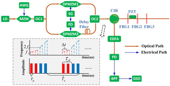
The structure of the proposed distributed fiber optic vibration sensing system is shown in Figure 1. An optical carrier output from a laser diode (LD) is modulated into a dual-pulse signal using a Mach-Zehnder modulator (MZM). The dual-pulse modulation signal is generated with an arbitrary waveform generator (AWG). Then the optical signal is split into two paths via a 50/50 optical coupler (OC1). For the upper path, a dual-parallel MZM (DPMZM1) is employed to implement carrier-suppressed single-sideband (CS-SSB) modulation on a linear chirp signal generated by a signal generator (SG). For the lower path, DPMZM2 performs CS-SSB modulation on the frequency-doubled linear chirp signal, which is produced by a frequency doubler (FD), and a fixed time delay is introduced in the lower path via a delay fiber. After combining the two-path signals with OC2, a dual-chirped pulse signal is generated, and it is fed into the WFBG array through an optical circulator (CIR). The reflected optical signal is first amplified by an erbium-doped fiber amplifier (EDFA) and then converted into an electrical signal by a photodetector (PD), followed by a band-pass filter (BPF). The filtered signal is subsequently recorded by a digital storage oscilloscope (DSO). Finally, vibration localization and measurement are achieved through data acquisition and phase demodulation algorithms.
Figure 1.
Schematic diagram of the proposed distributed fiber optic vibration sensing system. The inset: time-frequency characteristics and waveform of the generated optical sensing signal. Inset: Red color: the signal output from DPMZM1; blue color: the signal output from DPMZM2.
2.1. Principle of Sensing Signal Generation
The optical carrier output by the laser can be expressed as , where and are the amplitude and frequency of the optical carrier, respectively. The optical carrier is pulse-modulated by the MZM, and the modulating signal is a dual-pulse sequence, which can be written as
where is the amplitude of the pulse signal, rect(·) is the rectangular function, used to define the shape of the rectangular pulse, denotes the pulse width, is the pulse period, and is the time delay between the two pulses. The output signal of MZM can be expressed as
where the MZM is biased at its minimum transmission point and is the half-wave voltage of MZM. It can be seen from Equation (2) that if the amplitude of the pulse signal is equal to , then a high-extinction-ratio pulse modulation can be achieved. The pulse-modulated optical signal is split into two paths via a 50/50 optical coupler, which are modulated by the linear chirp signal and the frequency-doubled linear chirp signal, respectively. The linear chirp signal can be expressed as
where , and are the amplitude, starting frequency and chirp rate of the linear chirp signal, respectively. The frequency-doubled signal of the LFM can be expressed as
where is the amplitude of the frequency-doubled linear chirp signal. In both path, two DPMZMs are utilized to implement CS-SSB modulation. The outputs of the two DPMZMs can be expressed as
where high-order and DC components are ignored. It can be inferred from Equations (5) and (6) that the proposed scheme achieves pulse modulation of the linear chirp signal and its frequency-doubled signal in the optical domain, enabling each DPMZM to generate dual-chirped pulses with different starting frequencies. For DPMZM1, the starting frequencies of the output dual-chirped pulses are and , respectively; for DPMZM2, the starting frequencies of the output dual-chirped pulses are and , respectively. To realize FDM and improve the system’s response bandwidth, the output signal of the lower path is delayed by , and the delayed signal is expressed as . After the two paths of signals are combined by OC2, the desired sensing signal is obtained, as illustrated by the time–frequency characteristics in the inset of Figure 1, where the red color represents the signal output from DPMZM1, and the blue color represents the signal output from DPMZM2.
2.2. Principle of Vibration Measurement
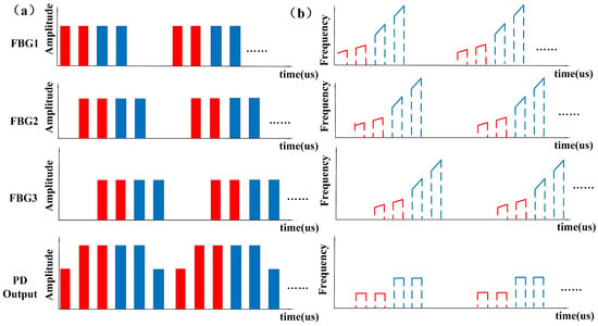
The generated FDM dual-chirped pulse sensing signal is injected into the WFBG array via an optical circulator. The distance between two adjacent FBGs is , corresponding to a signal time delay of , where is the effective refractive index of the optical fiber and is the light velocity in vacuum. When the time delay between the two pulses is adjusted such that , the two pulses will overlap in the time domain after being reflected by the WFBG array, as shown in Figure 2. As a result, self-heterodyne detection is realized, and a beat signal is generated. By demodulating the phase of the beat frequency signal, the target vibration information can be obtained.
Figure 2.
Schematic illustration of the signals reflected from the WFBG array. (a) Waveforms; (b) time-frequency characteristics.
To simplify the analysis, the dual-chirped pulse generated in path1 is first considered. Assume that a disturbance occurs between the i-th FBG and the (i + 1)-th FBG, the first chirped pulse reflected by the (i + 1)-th FBG can be expressed as
where represents the change in fiber length induced by vibration, and denote the time and phase variation caused by , respectively. The second chirped pulse reflected by the i-th FBG can be expressed as
Both reflected pulses share the same time delay. After being converted into an electrical signal via a photodetector, and with the high-frequency and DC components ignored, the resulting signal can be expressed as
where , . As can be seen from Equation (9), a beat signal with a frequency of is generated. This relationship reveals the mechanism for relaxing pulse width constraints in LFM-based systems. Similarly, for the dual-chirped pulse generated in path2, the generated beat signal can be expressed as
where . It can be inferred from Equations (9) and (10) that the vibration signal to be measured is mapped to the phases of the two beat signals. Therefore, it can be obtained by phase demodulating the two beat signals.
3. Simulation Results
The system depicted in Figure 1 was simulated and verified using MATLAB(2024a) according to the above theoretical analyses. To balance sampling accuracy and computational efficiency, and in accordance with practical experimental hardware constraints, the sampling frequency was set to 40 GHz. The total simulation time was set to 100 μs, resulting in 4 × 10⁶ sampling points. Regarding the optical carrier, the input power was set to 10 dBm at 1550 nm. For the dual-pulse modulation signal, the pulse period is 2 μs, corresponding to a maximum sensing distance of 500 m. The pulse width is 250 ns, and the time delay between the two pulses is 500 ns. The continuous linear chirp modulation signal has a starting frequency of 1 GHz and a chirp rate of 200 MHz/μs. The period of the chirp signal is the same as that of the dual-pulse signal. The time delay introduced in path2 is 1 μs. The WFBG array consists of three gratings, with a spacing of 50 m between adjacent gratings. The reflectivity of each FBG is set to be 0.7%, employing a low-reflection design to avoid interference from multiple reflections. The main parameters of the sensing system are summarized in Table 1.
Table 1.
Main parameters used in the simulation.
3.1. Sensing Signal Generation
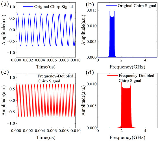
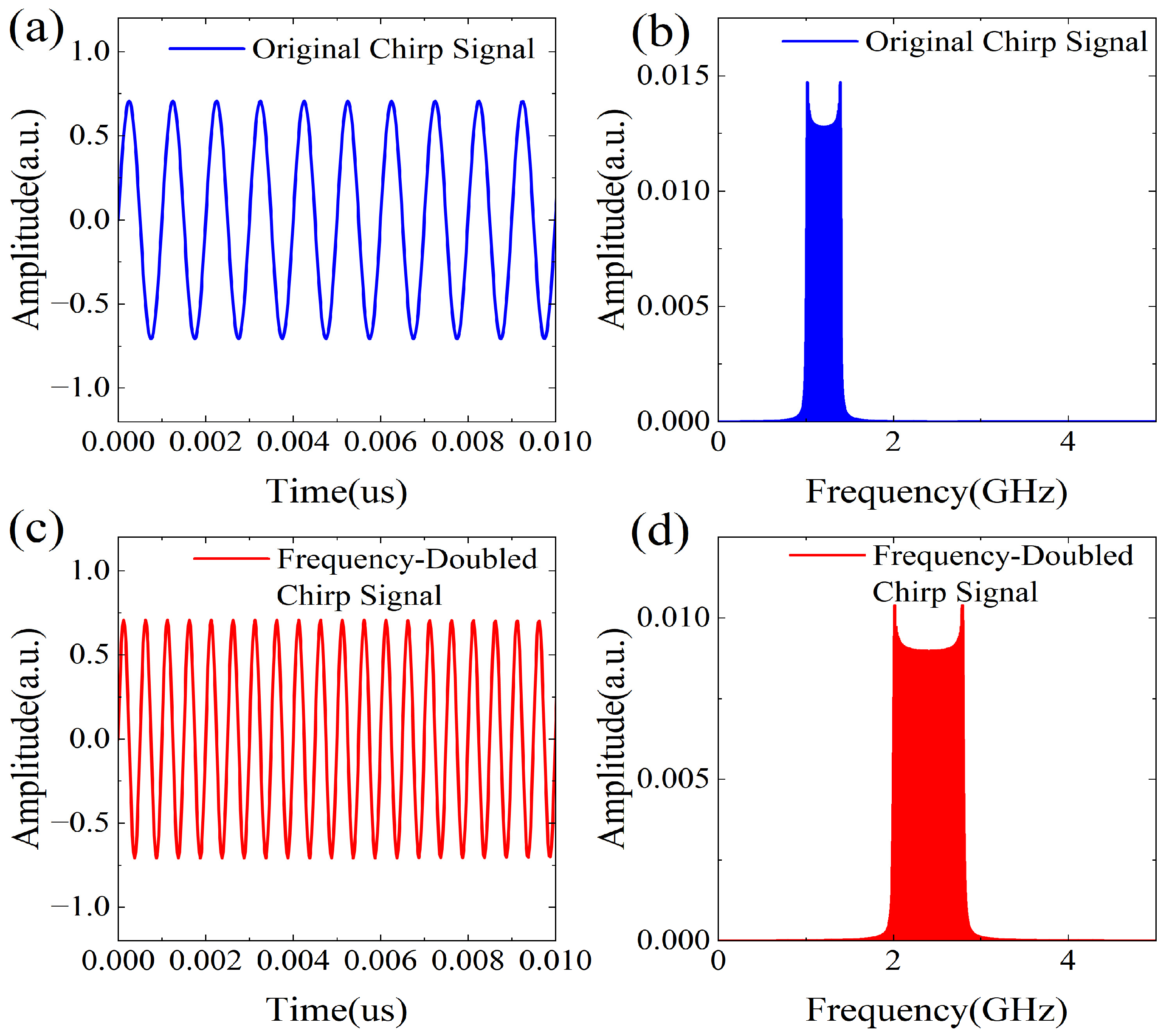
The optical carrier is first modulated by a dual-pulse signal using an MZM with a half-wave voltage of 3.5 V. The output signal from MZM is calculated according to Equation (2). Then it is split into two paths. One path is modulated by a chirp signal, while the other is modulated by its frequency-doubled counterpart. The chirp signal and frequency-doubled chirp signal are generated based on Equations (3) and (4). Figure 3 shows the corresponding waveforms and frequency spectra of the chirp signal and frequency-doubled chirp signal. In the simulation, both modulation signals are set to have the same amplitude. As can be seen from Figure 3, the chirp signal occupies a frequency range of 1–1.4 GHz, whereas the frequency-doubled chirp signal spans 2–2.8 GHz.
Figure 3.
(a) Waveform and (b) frequency spectrum of the modulation chirp signal. (c) Waveform and (d) frequency spectrum of the frequency-doubled chirped signal.
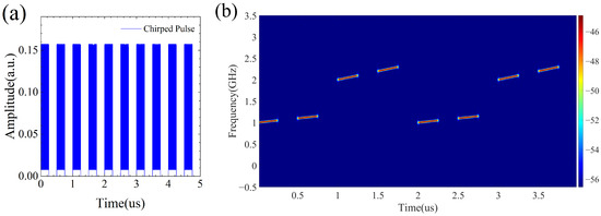
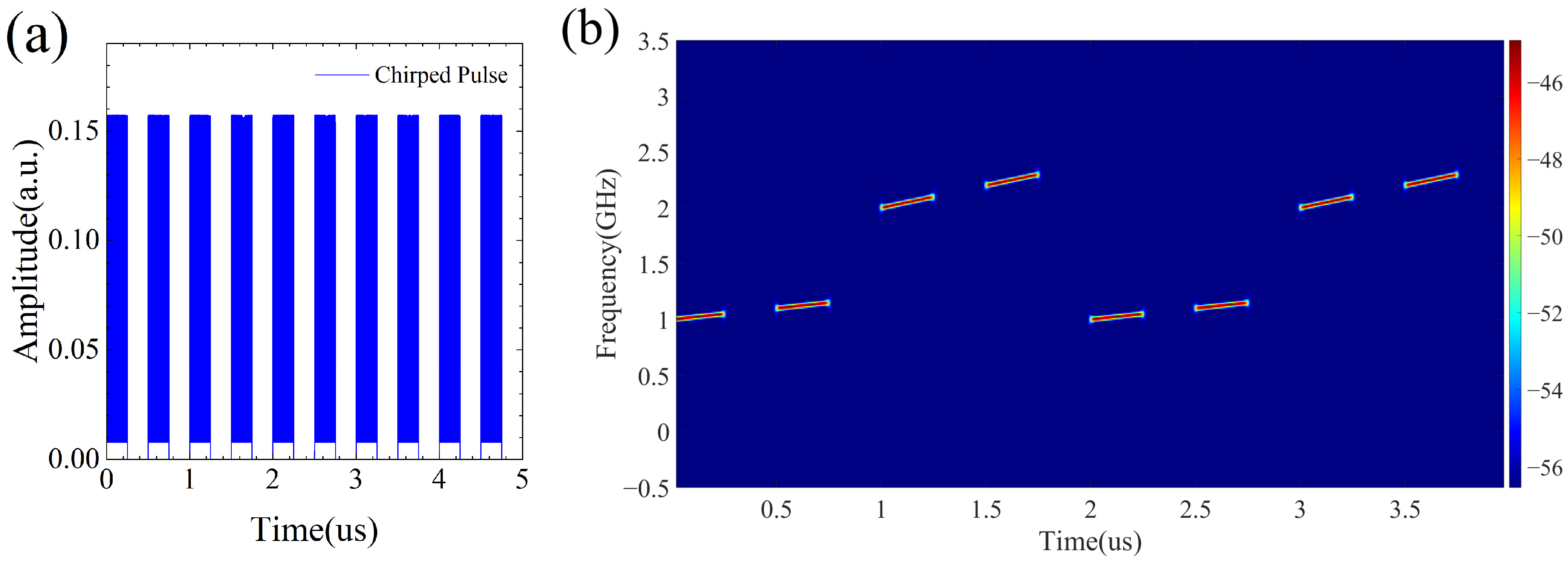
In both paths, DPMZMs are utilized to achieve CS-SSB modulation. Each DPMZM is modeled based on its nested dual-parallel Mach-Zehnder configuration, including two sub-MZMs and a parent MZM. The two sub-MZMs are biased at the null point to suppress the optical carrier, while the parent MZM introduces a π/2 phase shift to generate the CS-SSB modulated signal. The output of DPMZM2 is digitally delayed by an appropriate number of sampling points to introduce a temporal offset of 1 μs. After combining the two path signals, the optical sensing signal is finally generated, as illustrated in Figure 4. From the time-frequency characteristics of the sensing signal shown in Figure 4b, we can see that two pairs of dual-chirped pulse signals with different chirp rates are generated within one signal period, and the two pulses in each pair have different starting frequencies. Consequently, two beat signals with different frequencies are obtained after reflection from the WFBG array. Both beat signals encode the target vibration information, enabling FDM and thereby improving the system response bandwidth. It should be noted that the sampling frequency in the simulation is set to 40 GHz, whereas the optical carrier wavelength is 1550 nm, corresponding to an optical frequency on the order of hundreds of terahertz. Since the optical carrier frequency is far beyond the sampling frequency, the directly sampled spectrum does not represent the absolute optical frequency of the signal. For the result shown in Figure 4b, the signal is first downconverted to the radio-frequency domain. Specifically, the CS-SSB modulated signal is mixed with the optical carrier, generating a beat-frequency signal. Therefore, the resulting frequency components start from 1 GHz, corresponding to the starting frequency of the chirp signal rather than the optical carrier frequency.
Figure 4.
(a) Waveform and (b) time-frequency characteristics of the generated sensing signal.
3.2. Vibration Measurement
The generated optical sensing signal is injected into the WFBG array via an optical circulator. The FBG array was modeled as a set of discrete reflective elements. The reflected optical field from the i-th FBG is represented as a delayed and attenuated replica of the incident signal, and it can be expressed as
where is the round-trip propagation delay determined by the fiber length . The total reflected optical field is obtained by coherently summing the contributions from all FBGs:
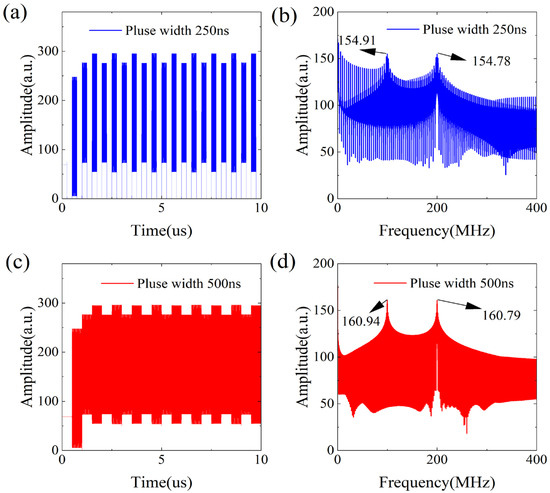
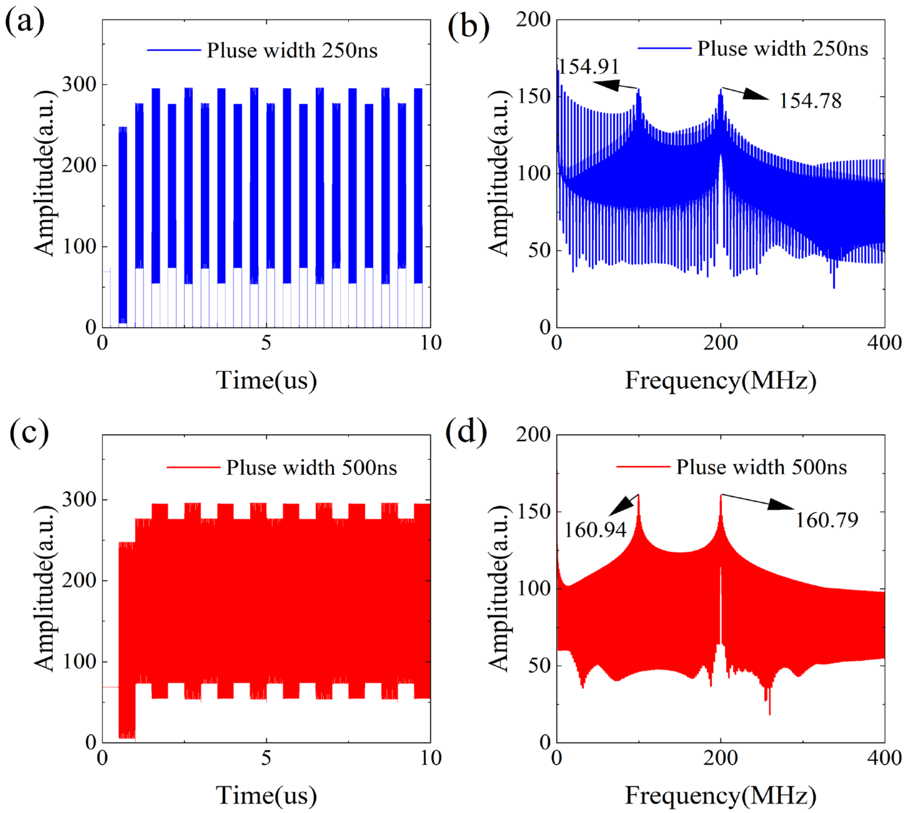
The reflected signal is amplified by an EDFA and subsequently detected using a 1-GHz PD. In the simulation, the PD is modeled as a square-law detector followed by a low-pass filter with a bandwidth of 1 GHz. Figure 5 shows the PD output, where Figure 5a depicts the time-domain waveform and Figure 5b presents the corresponding frequency spectrum. From Figure 5a, we can see that there are four pulses in each period. The first and third pulses correspond to the beat signals generated by the reflection signals from the first two FBGs, while the second and fourth pulses correspond to the beat signals generated by the reflection signals from the latter two FBGs. As observed in Figure 5b, two dominant spectral peaks appear at 100 MHz and 200 MHz, respectively, corresponding to the two beat signals generated by the two pairs of dual-chirped pulse signals. Because of the time-frequency characteristics of chirp signals, the proposed scheme permits a pulse width as large as the time delay between adjacent FBGs, which is beneficial for improving the system SNR. To verify this, the pulse width is extended to 500 ns, and the results are illustrated in Figure 5c,d. It can be seen that the amplitudes of the 100 MHz and 200 MHz signals are increased by approximately six units. It should be noted that when the pulse width is equal to the time delay between adjacent FBGs, the two pulses are merged into a single pulse, as shown in Figure 5c. In this case, the optical carrier can be regarded as being modulated by a chirped pulse signal and its frequency-doubled counterpart, respectively.
Figure 5.
(a) Time-domain waveform and (b) spectrum of PD output with 250 ns pulse width. (c) Time-domain waveform and (d) spectrum of PD output with 500 ns pulse width.
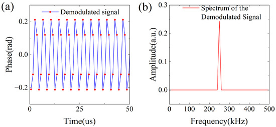
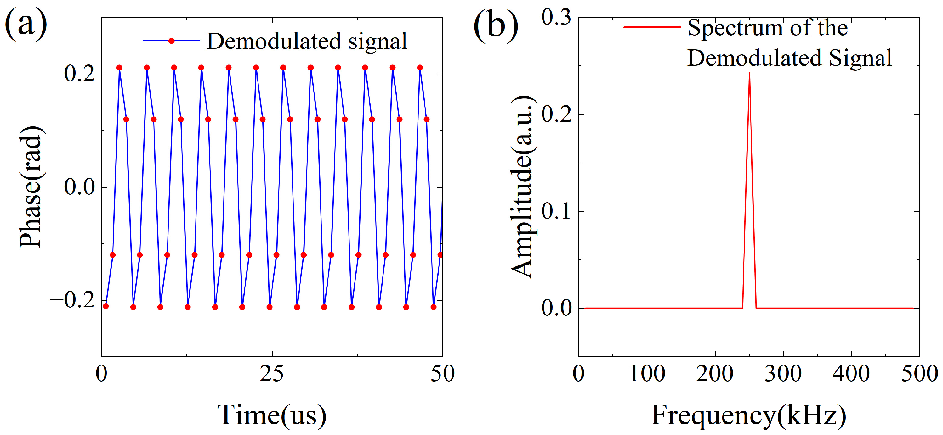
According to the theoretical part, when a disturbance occurs between the adjacent FBGs, it will be mapped into the phases of the 100 MHz and 200 MHz beat signals. Then, the vibration to be measured can be obtained by performing phase demodulation of these two beat signals. In our simulation, a vibration signal with a frequency of 250 kHz is added between the first and second FBG. The vibration-induced phase modulation is applied to the reflected signal from the FBG located after the vibration region. The phase demodulation is implemented using an arctangent algorithm. The digitized output signal from PD is mixed with in-phase and quadrature local oscillator signals to obtain the baseband I/Q components. The instantaneous phase is then retrieved via an arctangent operation. To suppress temporal fluctuations and improve phase stability, centralized window averaging is performed over the effective pulse duration. For the FDM scheme, parallel demodulation branches with different local oscillator frequencies are employed. Each branch demodulates the vibration signal at different time instants, thereby effectively increasing the overall sampling rate of the system.
Figure 6 shows the demodulated results for the first and third pulses in each period. In terms of demodulation performance, the transmission of each detection pulse in the system can be regarded as a sampling of the vibration signal; thus, the vibration sampling rate is equivalent to the pulse repetition rate. Without FDM, the pulse repetition period is 2 μs and the system sampling rate is 500 kHz. After FDM implementation, the system sampling rate is increased to 1000 kHz. Therefore, for a 250 kHz vibration signal, there are four sampling points in each period.
Figure 6.
(a) Time-domain waveform and (b) spectrum of the demodulated vibration signal.
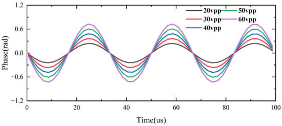
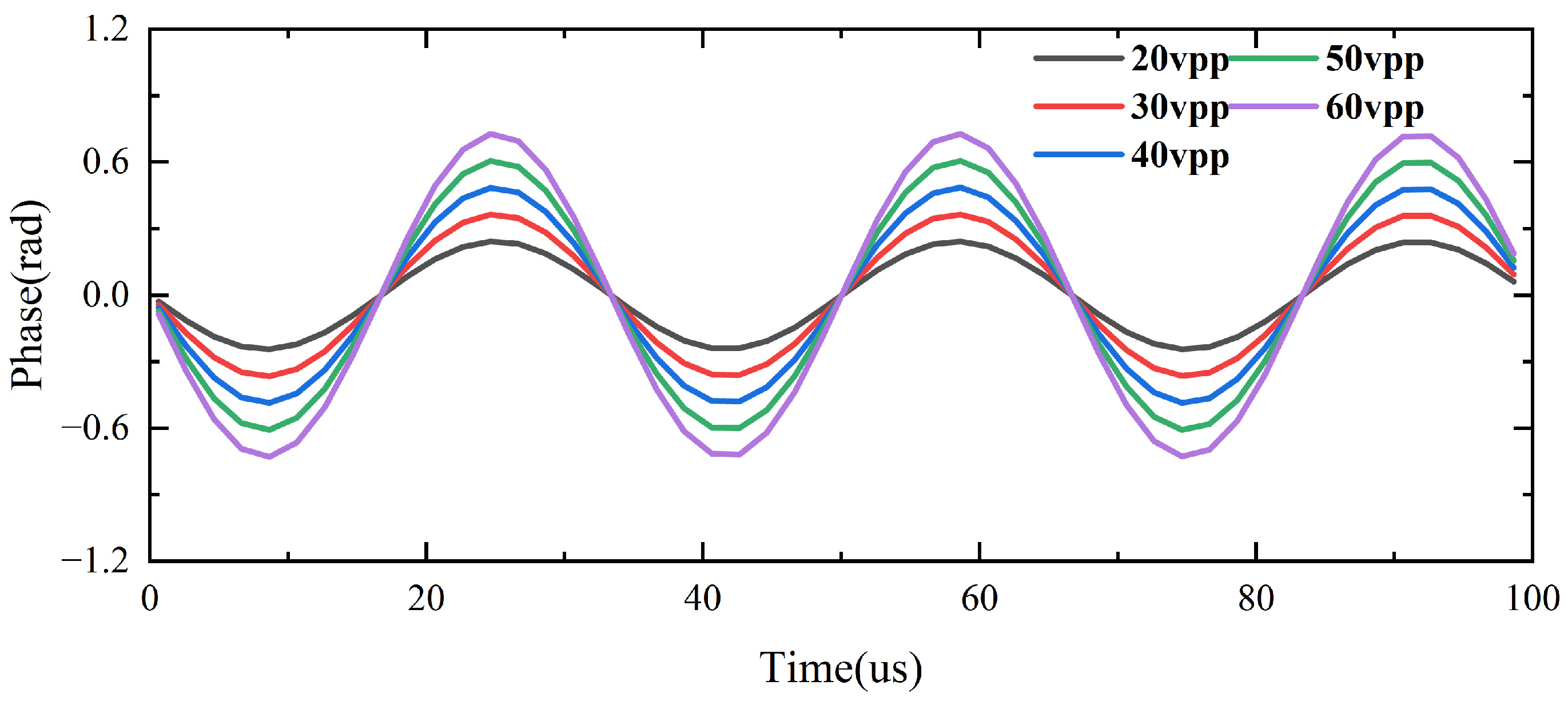
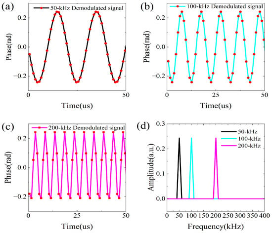
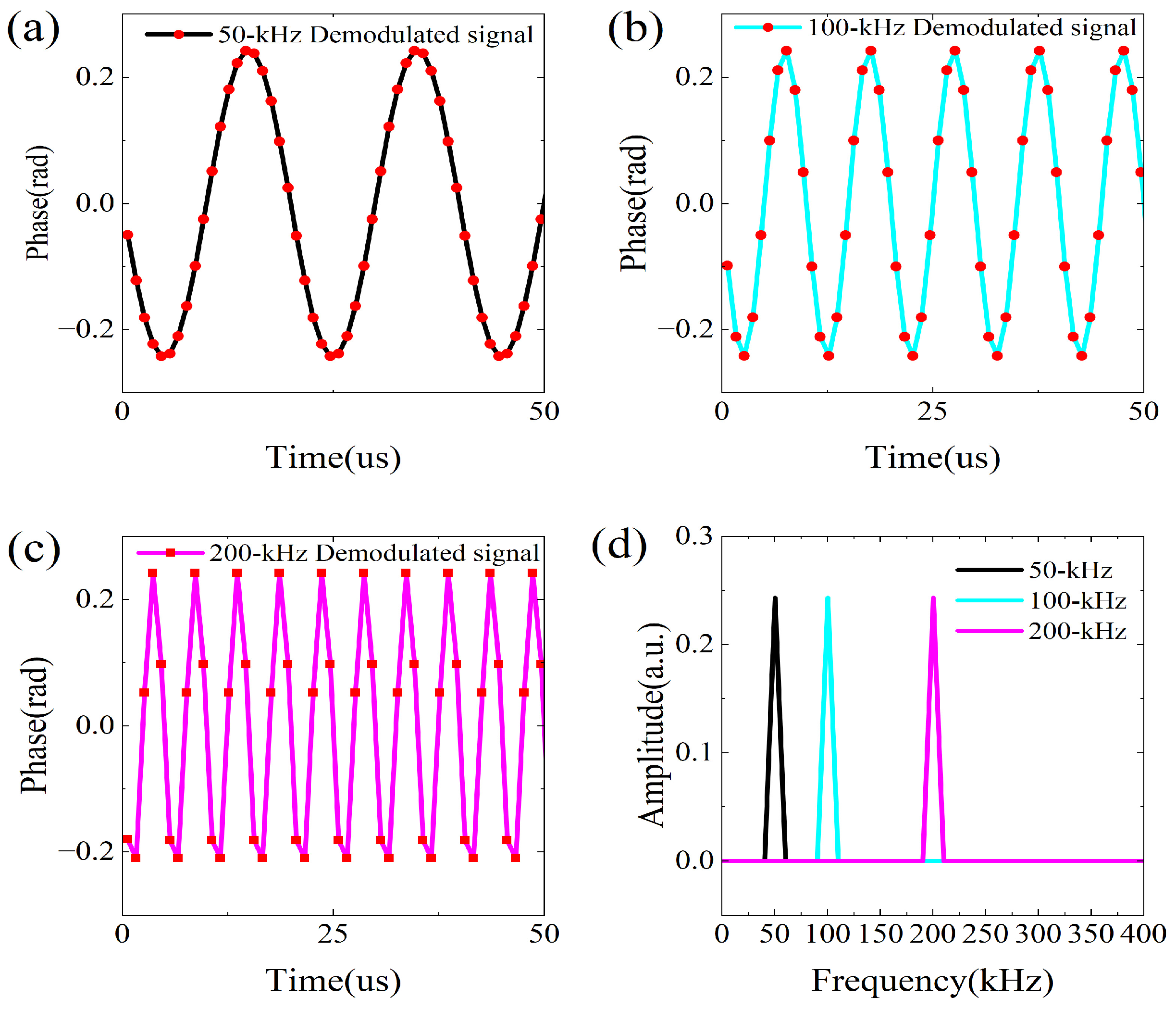
Then the amplitude and frequency of the applied vibration signal are successively varied to verify the feasibility of the system. Figure 7 shows the demodulation results of a 30 kHz vibration signal with different amplitudes. It can be observed that, as the vibration amplitude increases, the amplitude of the demodulated signal increases accordingly, which is consistent with practical measurement results. Figure 8 presents the demodulation results for vibration signals with the same amplitude but different frequencies. The results indicate that the proposed system can correctly demodulate vibration signals at different frequencies, thereby verifying the reliability of the proposed scheme.
Figure 7.
Demodulated results for vibration signals with different amplitudes.
Figure 8.
Demodulated results for vibration signals with different frequencies. Demodulated waveforms of (a) 50 kHz, (b) 100 kHz, and (c) 200 kHz vibration signals. (d) Spectrum of the demodulated signal.
Although the present study is conducted through numerical simulations, the proposed architecture is compatible with existing microwave photonic technology. All required components, including DPMZMs, arbitrary waveform generators, lasers, and fiber delay lines, are commercially available. There are no stringent requirements on device performance, and the signal frequency is relatively low. The fixed delay between the two optical paths can be implemented using a calibrated fiber delay line. Moreover, high delay accuracy is not critical, since the two optical paths operate independently.
Since dual-chirped-pulse-based distributed sensing schemes have already been experimentally demonstrated in [18], the primary practical challenge lies in the stable generation of dual-chirped pulses. In this work, dual-chirped signal generation is implemented using a microwave photonic approach, which has been extensively investigated for chirped pulse generation and applied in radar systems [19,20]. The key mechanism is the CS-SSB modulation based on DPMZM. The carrier suppression ratio plays a crucial role in both signal generation and overall vibration sensing performance. Fortunately, the carrier suppression ratio can exceed 25 dB [21,22], under which condition the influence of the residual carrier can be neglected. In addition, the bias stabilization circuits can be employed to maintain long-term stability of CS-SSB modulation.
The interferometric structure formed by the two optical paths may also influence signal generation. When the carrier suppression ratio is sufficient, as said before, the two optical paths carry signals at different frequencies, and the resulting beat-frequency component lies well beyond the detection bandwidth, allowing it to be effectively filtered. In contrast, insufficient carrier suppression may cause interference between the residual carrier components, leading to signal power fluctuations. Nevertheless, as long as the signal remains detectable, the demodulation accuracy is not compromised, since the vibration information is encoded in the phase of the beat-frequency signal rather than in its amplitude.
Furthermore, the incorporation of a grating array enhances the system’s noise tolerance and robustness. In summary, the proposed scheme is practically feasible and provides a solid foundation for subsequent experimental validation, which will constitute the focus of future work.
When compared with traditional dual-pulse heterodyne systems, the proposed dual-chirp pulse scheme offers several advantages. Regarding the relaxation of pulse width constraints, conventional dual-pulse systems require the pulse width to be strictly shorter than the round-trip time between gratings. In contrast, our scheme exploits the time-frequency mapping property of LFM signals, allowing longer pulses to overlap in the time domain while remaining separable in the frequency domain. This enables higher pulse energy injection and a significant improvement in SNR without compromising spatial resolution. In terms of response bandwidth enhancement, compared to the work in [18], our FDM approach theoretically doubles the effective sampling rate by multiplexing two distinct chirp rates, enabling the system to detect high-frequency vibrations that would otherwise be aliased.
4. Conclusions
This paper proposes a distributed fiber optic vibration sensing system based on FDM dual-chirped pulses and a WFBG array. In the proposed system, a self-heterodyne detection method is employed to demodulate vibration-induced phase variations, leveraging the fixed spatial positions of the FBGs. Owing to the time-frequency characteristics of chirped pulse signals, the pulse width can be relaxed to be equal to the time delay between adjacent FBGs, enabling self-heterodyne detection using a single-pulse signal. The feasibility of the proposed scheme is verified through theoretical analysis and numerical simulations. Furthermore, frequency-doubled signals are introduced to implement FDM, thereby enhancing the system response bandwidth. These approaches provide an effective solution for long-distance fiber-optic vibration sensing with a high SNR.
Author Contributions
Conceptualization, H.P. and J.Z.; methodology, J.Z.; software, H.P.; validation, H.P., J.Z. and S.H.; formal analysis, H.P.; investigation, J.Z.; resources, J.Z.; data curation, H.P.; writing—original draft preparation, H.P.; writing—review and editing, J.Z., S.H. and Y.W.; visualization, H.P.; supervision, Y.W. and S.H.; project administration, J.Z. and Y.W.; funding acquisition, J.Z. and Y.W. All authors have read and agreed to the published version of the manuscript.
Funding
This research was funded by the Beijing Natural Science Foundation under Grant 4242001 and in part by the National Natural Science Foundation of China under Grant 62275008.
Data Availability Statement
The novel findings and original data of this study are incorporated into the main text of the article. For additional information or inquiries, please contact the corresponding authors. All original contributions generated in this research are included within the published article. Should further details be required, correspondence may be addressed to the corresponding authors.
Conflicts of Interest
The authors declare no conflicts of interest.
References
- Marie, T.F.B.; Bin, Y.; Dezhi, H.; Bowen, A. Principle and application state of fully distributed fiber optic vibration detection technology based on Φ-OTDR: A review. IEEE Sens. J. 2021, 21, 16428–16442. [Google Scholar] [CrossRef] [Scilit]
- Wang, C.; Zhang, R.; Zhang, H.; Yang, Y.; Ma, Y.; Meng, J. Distributed fiber optic warning identification algorithm for oil and gas pipelines based on the inception DVS model. Flow Meas. Instrum. 2025, 102, 102802. [Google Scholar] [CrossRef] [Scilit]
- Jousset, P.; Reinsch, T.; Ryberg, T.; Blanck, H.; Clarke, A.; Aghayev, R.; Hersir, G.P.; Henninges, J.; Weber, M.; Krawczyk, C.M. Dynamic strain determination using fibre-optic cables allows imaging of seismo-logical and structural features. Nat. Commun. 2018, 9, 2509. [Google Scholar] [CrossRef] [Scilit] [PubMed]
- Liang, S.; Zhang, C.; Lin, W.; Li, L.; Li, C.; Feng, X.; Lin, B. Fiber-Optic Intrinsic Distributed Acoustic Emission Sensor for Large Structure Health Monitoring. Opt. Lett. 2009, 34, 1858–1860. [Google Scholar] [CrossRef] [Scilit]
- Zinsou, R.; Liu, X.; Wang, Y.; Zhang, J.; Wang, Y.; Jin, B. Recent Progress in the Performance Enhancement of Phase Sensitive OTDR Vibration Sensing Systems. Sensors 2019, 19, 1709. [Google Scholar] [CrossRef] [Scilit]
- Peng, F.; Wu, H.; Jia, X.-H.; Rao, Y.-J.; Wang, Z.-N.; Peng, Z.-P. Ultra-Long High-Sensitivity φ-OTDR for High Spatial Resolution Intrusion Detection of Pipelines. Opt. Express 2014, 22, 13804–13810. [Google Scholar] [CrossRef] [Scilit]
- Hussels, M.-T.; Chruscicki, S.; Arndt, D.; Scheider, S.; Prager, J.; Homann, T.; Habib, A.K. Localization of transient events threatening pipeline integrity by fiber-optic distributed acoustic sensing. Sensors 2019, 19, 3322. [Google Scholar] [CrossRef] [Scilit]
- Yang, G.; Fan, X.; Wang, S.; Wang, B.; Liu, Q.; He, Z. Long-Range Distributed Vibration Sensing Based on Phase Extraction from Phase-Sensitive OTDR. IEEE Photonics J. 2016, 8, 7458125. [Google Scholar] [CrossRef] [Scilit]
- Sun, Z.; Fang, M.; Huang, D.; Yang, H.; Zhao, C.; Li, S.; Liu, F. An unsupervised learning method to enhance SNR for distributed optical fiber vibration sensor based on phase-sensitive OTDR. Opt. Laser Technol. 2025, 180, 111570. [Google Scholar] [CrossRef] [Scilit]
- Lin, Z.; He, H.; Zhao, Z.; Tong, W.; Tang, M. Frequency Response Enhanced Quantitative Vibration Detection Using Fading-Free Coherent-OTDR with Randomized Sampling. J. Light. Technol. 2023, 41, 5159–5168. [Google Scholar] [CrossRef] [Scilit]
- Gui, X.; Li, Z.; Fu, X.; Guo, H.; Wang, Y.; Wang, C.; Wang, J.; Jiang, D. Distributed Optical Fiber Sensing and Applications Based on Large-Scale Fiber Bragg Grating Array. J. Light. Technol. 2023, 41, 4187–4200. [Google Scholar] [CrossRef] [Scilit]
- Zhu, F.; Zhang, Y.; Xia, L.; Wu, X.; Zhang, X. Improved Φ-OTDR sensing system for high-precision dynamic strain measurement based on ultra-weak fiber Bragg grating array. J. Light. Technol. 2015, 33, 4775–4780. [Google Scholar]
- Sandah, F.; Dossou, M.; Kinet, D.; Dandu, P.; Wuilpart, M. Study and mitigation of polarization fading in FBG-assisted direct-detection φ-OTDR. Opt. Express 2025, 33, 10873–10885. [Google Scholar] [CrossRef] [Scilit] [PubMed]
- Liu, C.; Wang, Y.; Tang, K.; Tang, J.; Cheng, C.; Yang, M. Distributed Multi-Parameter Sensing Using Composite Optical Fibers of Hybrid Ultra-Weak Fiber Bragg Gratings. Opt. Laser Technol. 2025, 180, 111503. [Google Scholar] [CrossRef] [Scilit]
- Wu, M.; Fan, X.; Zhang, X.; Yan, L.; He, Z. Frequency Response Enhancement of Phase-Sensitive OTDR for Interrogating Weak Reflector Array by Using OFDM and Vernier Effect. J. Light. Technol. 2020, 38, 4874–4882. [Google Scholar] [CrossRef] [Scilit]
- Zhou, C.; Pang, Y.; Qian, L.; Chen, X.; Xu, Q.; Zhao, C.; Zhang, H.; Tu, Z.; Huang, J.; Gu, H.; et al. Demodulation of a Hydroacoustic Sensor Array of Fiber Interferometers Based on Ultra-Weak Fiber Bragg Grating Reflectors Using a Self-Referencing Signal. J. Light. Technol. 2018, 37, 2568–2576. [Google Scholar] [CrossRef] [Scilit]
- Shan, Y.; Ji, W.; Dong, X.; Cao, L.; Zabihi, M.; Wang, Q.; Zhang, Y.; Zhang, X. An Enhanced Distributed Acoustic Sensor Based on UWFBG and Self-Heterodyne Detection. J. Light. Technol. 2019, 37, 2700–2705. [Google Scholar] [CrossRef] [Scilit]
- Liang, G.; Jiang, J.; Liu, K.; Wang, S.; Xu, T.; Chen, W.; Ma, Z.; Ding, Z.; Zhang, X.; Zhang, Y.; et al. Phase Demodulation Method Based on a Dual-Identical-Chirped-Pulse and Weak Fiber Bragg Gratings for Quasi-Distributed Acoustic Sensing. Photon. Res. 2020, 8, 1093. [Google Scholar] [CrossRef] [Scilit]
- Li, J.; Xie, Y.; Wo, J.; Wang, X.; Yao, J. Multiband Microwave Photonic Radar with Increased Target Detection Ability. Opt. Lett. 2025, 50, 4094–4097. [Google Scholar] [CrossRef] [Scilit]
- Wang, Y.; Liu, X.; Zhang, J.; Wang, D.; Zhang, Y. Reconfigurable Generation of Switchable Multi-Format Linearly Frequency Modulated Signal at X-Band and K-Band with a Compact Photonics-Based Scheme. IEEE Photonics J. 2024, 16, 5500907. [Google Scholar] [CrossRef] [Scilit]
- Wang, Y.; Xu, J.; Wang, D.; Zhou, T.; Yang, D.; Zhong, X.; Yang, F. Microwave Photonic Mixer with Large Mixing Spurs Suppression and High RF/LO Isolation. Optik 2018, 174, 630–635. [Google Scholar] [CrossRef] [Scilit]
- Wang, Y.; Li, J.; Wang, D.; Zhou, T.; Xu, J.; Zhong, X.; Yang, D.; Rong, L. Ultra-Wideband Microwave Photonic Frequency Downconverter Based on Carrier-Suppressed Single-Sideband Modulation. Opt. Commun. 2018, 410, 799–804. [Google Scholar] [CrossRef] [Scilit]

Disclaimer/Publisher’s Note: The statements, opinions and data contained in all publications are solely those of the individual author(s) and contributor(s) and not of MDPI and/or the editor(s). MDPI and/or the editor(s) disclaim responsibility for any injury to people or property resulting from any ideas, methods, instructions or products referred to in the content. |
© 2026 by the authors. Licensee MDPI, Basel, Switzerland. This article is an open access article distributed under the terms and conditions of the Creative Commons Attribution (CC BY) license.