


Abstract
Gas ionization chambers face significant challenges in diagnosing laser-accelerated proton beams due to severe space charge effects induced by high peak currents and broad energy dispersion. These effects typically cause electric field distortion, signal saturation, and non-linear responses. In this study, we propose an optimized ionization chamber design that effectively mitigates space charge through a rigorous co-simulation approach. We combined ANSYS for macroscopic electrostatic field optimization with Garfield++ for microscopic charge transport modeling, explicitly incorporating ionization (Heed++) and electron drift/diffusion (Magboltz) processes. A systematic finite element modeling workflow—including gas volume meshing and the removal of dielectric components—was implemented to eliminate field non-uniformities and dielectric charging effects. Crucially, we validated the design’s performance against Boag’s theoretical recombination model. While theoretical calculations predict severe saturation (<80% efficiency) for standard chambers under high-flux conditions (107 protons/pulse), our simulation results demonstrate a strictly linear response with charge collection efficiency consistently exceeding 99.85%. Parametric studies further confirm that the optimized geometry and operational parameters (high bias, low pressure) successfully suppress space charge accumulation, providing a robust solution for laser-driven beam diagnostics.
1. Introduction
Cancer remains a leading cause of mortality worldwide [1]. Radiotherapy, particularly proton beam therapy, offers superior dose localization compared to conventional photon therapy due to the Bragg peak effect, which maximizes energy deposition within the tumor while sparing surrounding healthy tissue [2].
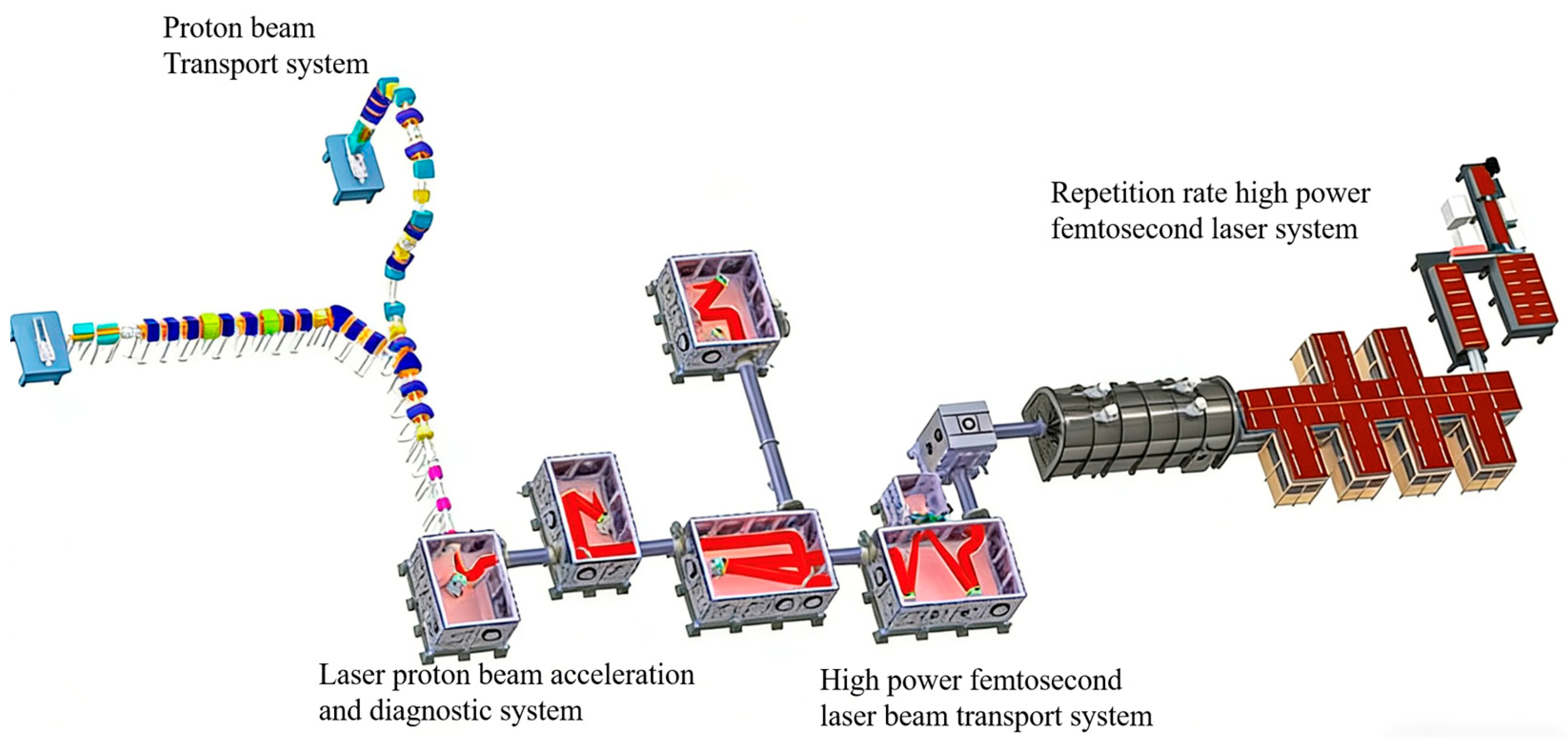
Traditional radiofrequency accelerators used for proton therapy are large and costly. Laser-driven plasma accelerators, capable of achieving exceptionally high acceleration gradients, present a promising alternative to reduce the scale and expense of proton therapy systems [3,4]. Recent advancements have demonstrated laser-accelerated protons with energies up to 70 MeV [5], and beams exceeding 100 MeV are sufficient for treating shallow-seated tumors [6,7]. This progress has spurred several international initiatives, including the Center for Advanced Laser Applications (CALA) in Germany [8,9], ELIMED in the EU [10,11], LhARA in the UK [12], and the CLAPA-II project in China [13,14], (as illustrated in Figure 1), which aim to deliver 100–200 MeV proton beams for clinical application.
Figure 1.
Layout of CLAPA-II.
Accurate beam diagnostics are paramount for the safe and effective application of these novel proton sources. Gas ionization chambers are the gold standard for beam monitoring in conventional proton therapy due to their reliability and stability. However, their performance is critically challenged by the unique characteristics of laser-accelerated beams: high peak current and large energy dispersion. These properties exacerbate space charge effects, where the slow drift of positive ions within the chamber creates a space charge cloud that distorts the internal electric field, leading to signal saturation, non-linear responses, and inaccurate position measurement [15]. Traditional analytical models, such as Boag’s theory, are often insufficient for predicting the complex space charge behaviors induced by these ultra-short, high-intensity pulses, necessitating rigorous numerical simulation.
This work addresses these challenges through an optimized design and analysis methodology. We employ a co-simulation approach using ANSYS 2021 R2 for electrostatic field optimization and Garfield++ 0.3 (master branch, https://garfieldpp.web.cern.ch/doxygen/index.html, accessed on 10 October 2023) for charge transport simulation. Our study provides a foundational framework for designing ionization chambers that are resilient to the space charge effects inherent in diagnosing laser-accelerated proton beams.
2. Principle and Technical Background
2.1. Gas Ionization Chamber Working Principle
When a charged particle traverses the sensitive gas volume of a parallel-plate ionization chamber, it ionizes gas molecules, creating electron-ion pairs along its trajectory. The initial kinetic energy of these charge carriers leads to diffusion, possible electron capture by neutral molecules, and recombination. An external electric field, applied between the cathode and anode, is essential to separate these pairs, driving electrons and positive ions toward their respective collecting electrodes. The resulting current and charge distribution signals are used to determine beam dose, position, and profile.
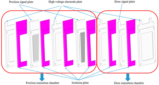
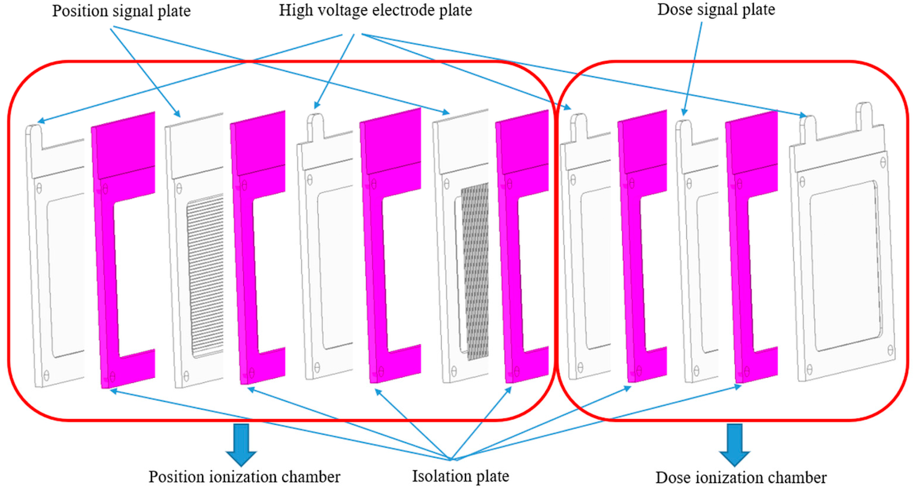
The working principle of a gas ionization chamber (as shown in Figure 2) involves charged particles passing through the sensitive volume of the gas parallel-plate ionization chamber. These charged particles interact with the gas, exciting gas molecules and ionizing them to produce an ion pair (a positive ion and an electron) along their trajectory. The generated ion pairs possess initial kinetic energy and continuously collide with gas molecules in the chamber. Three physical processes can occur for these ion pairs: (a) Diffusion: Positive ions and electrons drift from regions of high density to regions of low density. (b) Electron Capture: Electrons can be captured by neutral gas molecules in the chamber, forming negative ions. (c) Recombination: Positive ions and electrons can recombine to form neutral molecules. Therefore, a voltage must be applied across the two electrodes of the gas ionization chamber to establish an electric field between them. This field causes the positive ions and electrons to overcome the process above and drift towards their respective electrodes for collection. Multiple electrode plates are stacked. The electronics system connected to the dose ionization chamber region reads out the charge information. The position ionization chamber region determines the beam position based on signals from both the X and Y directions. The beam distribution information is obtained from the signals collected at the signal anode (collecting electrode) of the detector.
Figure 2.
Schematic diagram of the gas ionization chamber structure. The purple components represent FR4 isolation plates used to electrically insulate the high-voltage electrodes from the grounded signal plates. The red boundaries indicate the logical grouping of components into the Position Ionization Chamber (left) and Dose Ionization Chamber (right) modules.
2.2. Space Charge Effect and Its Influencing Factors
The space charge effect is the primary source of non-linearity in ionization chambers under high beam intensity. Its severity is not solely determined by the beam current but is governed by a combination of factors:
- (1)
- Beam Characteristics: High instantaneous beam intensity directly increases the charge density. Pulse duration and beam spot size determine the local space charge density, which dictates the severity of electric field distortion.
- (2)
- Gas Properties: The ion mobility of the fill gas is a critical parameter. Heavy gases like Argon have low mobility, leading to slow ion drift and significant charge accumulation. Lighter gases like Helium or Hydrogen offer higher mobility, facilitating faster charge clearance. Gas pressure and temperature also affect mobility, with higher pressure reducing it and higher temperature increasing it.
- (3)
- Chamber Design and Operational Parameters: The electric field strength (E = V/d) is a key design lever. A higher bias voltage or a smaller electrode spacing strengthens the electric field, accelerating charge drift and reducing the ion residence time, thereby mitigating space charge buildup.
- (4)
- Field Uniformity: Uniform electric fields ensure consistent charge drift velocities, preventing the formation of stagnant charge pockets that exacerbate recombination.
Therefore, the design objective is to optimize these controllable factors—specifically, the chamber geometry to ensure field uniformity and the operational parameters to maximize charge collection speed.
2.3. Simulation Framework and Physical Models
The simulation methodology employed in this study combines macroscopic electrostatic field calculation with microscopic charge transport modeling to ensure a physically rigorous analysis of space charge effects.
2.3.1. Electrostatic Field Calculation (ANSYS) [16]
ANSYS is utilized to solve the Poisson equation for the complex chamber geometry. The finite element analysis (FEA) provides a high-precision map of the electric potential (φ) and electric field vector (E) within the detector volume. This static field map serves as the boundary condition for the subsequent charge transport simulation.
2.3.2. Microscopic Charge Transport (Garfield++) [17]
Garfield++ serves as the interface to simulate the stochastic processes of particle interaction within the gas volume defined i ANSYS. To accurately capture the ionization and transport phenomena, the following physical models were integrated:
(1) Primary Ionization (Heed++) [18]: We utilized the Heed++ interface to model the interaction of high-energy protons (40–100 MeV) with helium atoms. Unlike simple energy deposition models, Heed++ treats the energy loss via the photo-absorption ionization (PAI) model, which accurately simulates the stochastic production of δ-electrons (delta-electrons) and the specific spatial distribution of electron-ion pairs along the particle track.
(2) Electron Transport (Magboltz) [19]: The transport properties of electrons in helium—specifically drift velocity (vd), longitudinal diffusion (DL), and transverse diffusion (DT)—were computed using Magboltz 11.10. The electron drift velocity is solved as a function of the electric field strength (E) and gas pressure (P) by numerically integrating the Boltzmann equation. For the helium gas used in this study, the drift velocity at the operating reduced field was calculated and verified against standard data tables.
(3) Signal Induction: The induced signal current on the electrodes was calculated using the Shockley-Ramo theorem. The instantaneous current i(t) is derived by summing the contribution of each drifting charge carrier relative to the weighting field of the readout electrode.
3. Ionization Chamber Structural Optimization and Electrostatic Analysis
This section details the optimized finite element modeling process in ANSYS, which is crucial for achieving a predictable electric field that resists space charge distortion.
3.1. Technical Scheme and Model Optimization
The core of our methodology involves a four-step model preparation process before electrostatic analysis: simplification, partitioning, trimming, and gas region solidification.
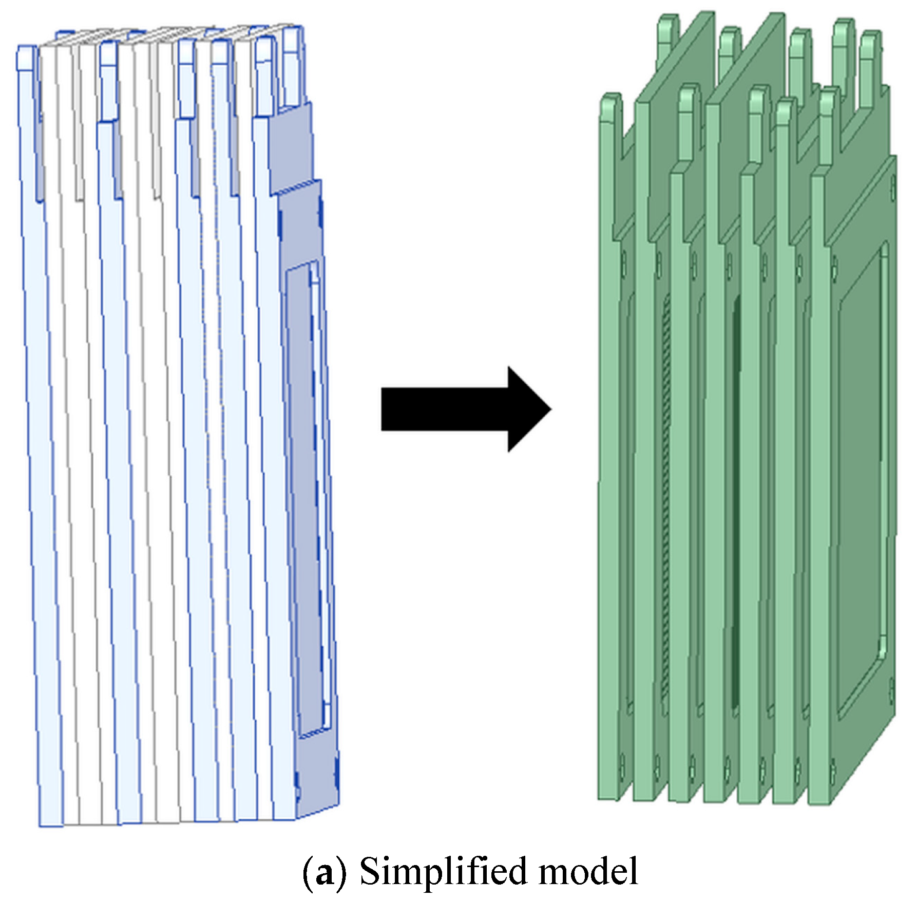
- Model Simplification: Insulating components (e.g., FR4 frames) located outside the active electrostatic region were removed (Figure 3a). This reduces mesh complexity and computational load without affecting the accuracy of the field solution.
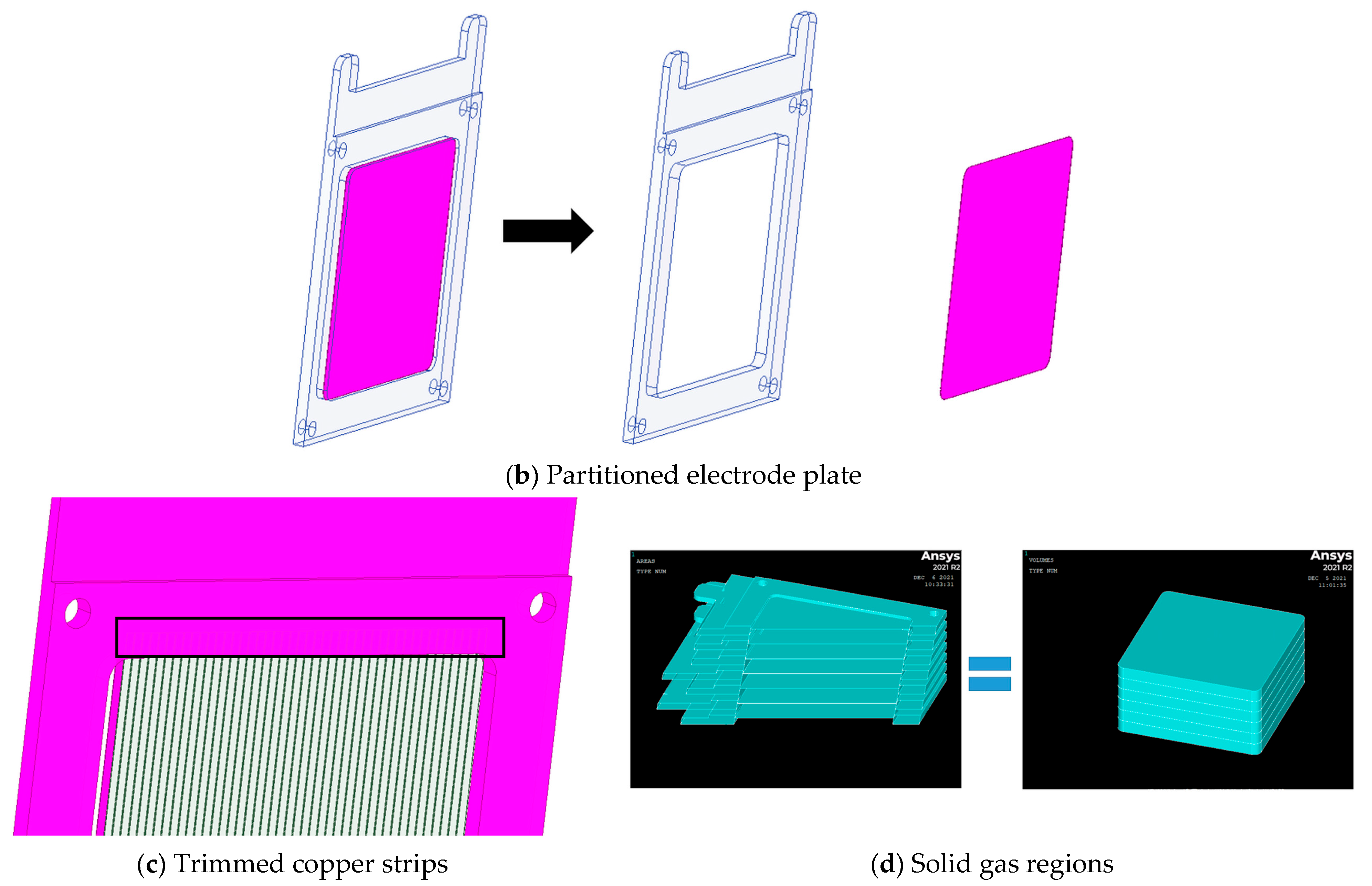
- Material Partitioning: The integrated electrode plate model was partitioned into distinct regions of different materials (e.g., aluminum sensitive area and FR4 insulator frame, as shown in Figure 3b). This facilitates the accurate assignment of material properties and boundary conditions.
- Model Trimming: Non-functional metallic parts embedded within insulating frames, such as the ends of copper strips (Figure 3c), were trimmed away. These elements do not contribute to signal collection but unnecessarily increase the number of mesh nodes and computational error.
- Gas Volume Mesh Definition (as illustrated in Figure 3): Instead of a simple “solidification,” this step involves the explicit definition of the gas fluid domain mesh between the electrodes (Figure 3d). In finite element analysis, the gas volume must be meshed to calculate the electric field vector at every node experienced by the drifting charges. Furthermore, the geometric optimization involved the removal of non-essential insulating components (FR4 frames) from the active region. This “trimming” process is critical not only for reducing mesh complexity but also for mitigating dielectric charging effects. Accumulation of static charge on insulating surfaces near the sensitive volume can distort the electric field and create dead zones where recombination is exacerbated; our optimized geometry eliminates this risk.
Figure 3.
Steps for optimizing the ANSYS model of the gas ionization chamber: (a) simplification, (b) material partitioning, (c) trimming of embedded components, and (d) solidification of the gas-filled volumes.
3.2. Electrostatic Field Results
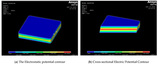
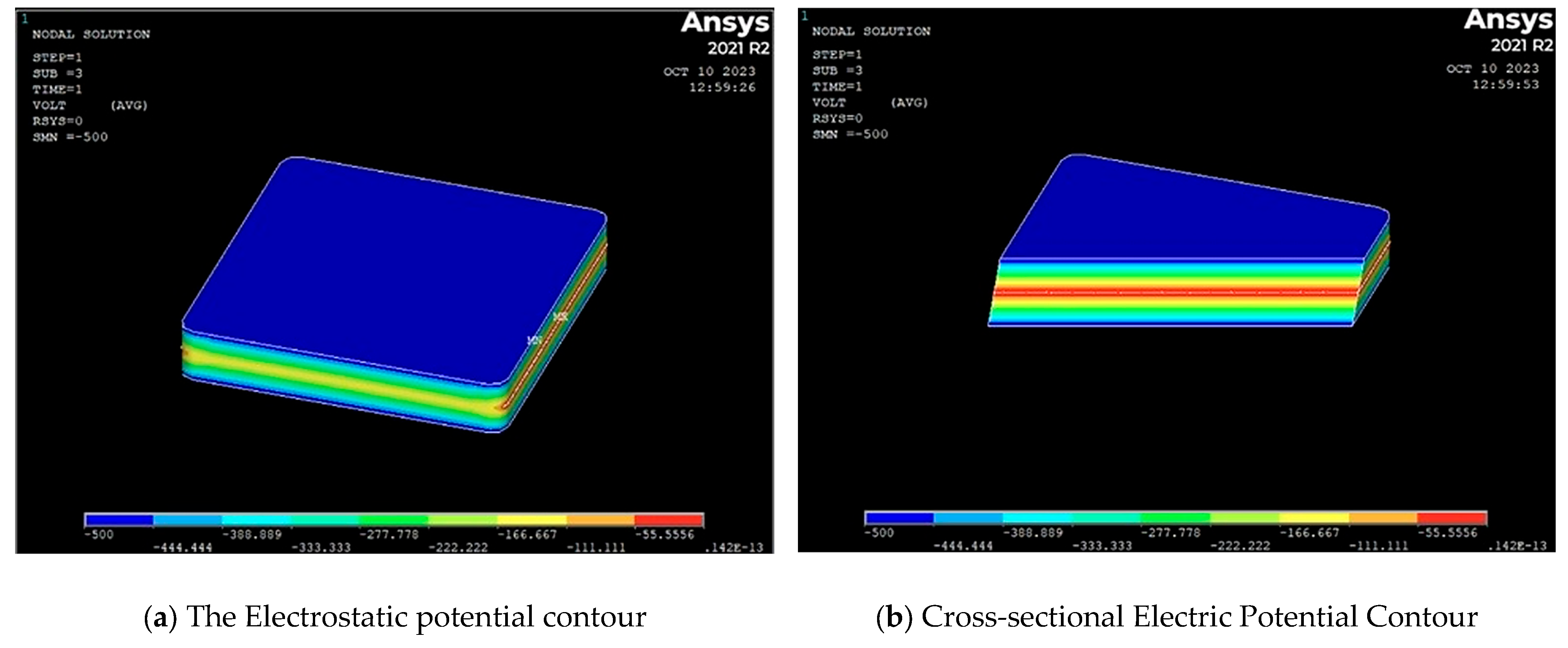
The optimized model was used to perform the finite element analysis. The resulting electrostatic potential contours are shown in Figure 4. The field distribution is highly uniform in the central sensitive volume of both the dose and position chambers, with smoothly bending field lines at the edges. This uniformity is vital, as it ensures consistent charge drift velocities and minimizes locations where space charge could preferentially accumulate and initiate severe distortion.
Figure 4.
Electrostatic potential contour plots from ANSYS FEA for (a) the dose ionization chamber and (b) Cross-sectional Electric Potential Contour.
4. Charge Transport Simulation and Parametric Performance Analysis
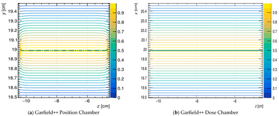
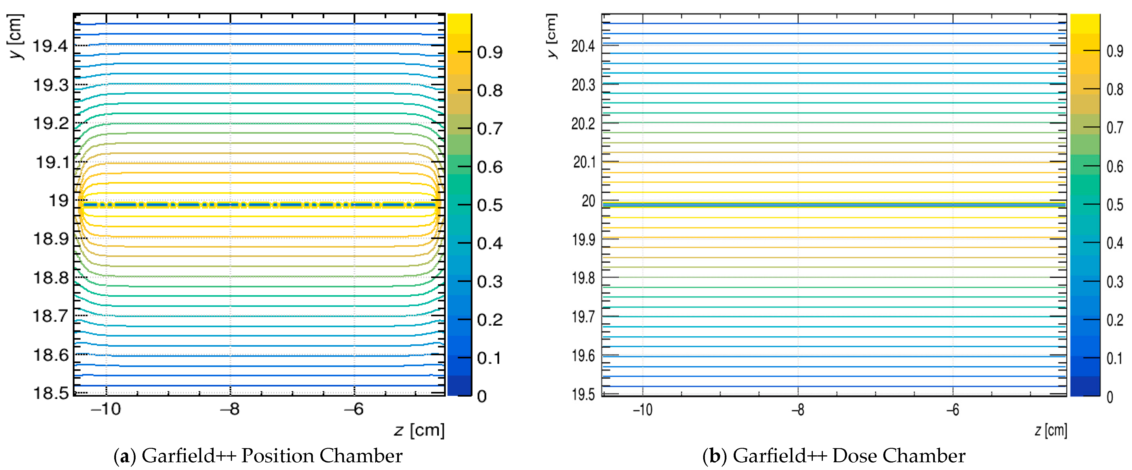
The ANSYS model was exported to Garfield++ to simulate the detector’s response and validate the design. The simulated potential distribution in Garfield++ (as shown in Figure 5) was identical to the ANSYS result, confirming the accuracy and reliability of the model transfer.
Figure 5.
Electrostatic potential distribution in Garfield++, confirming consistency with the ANSYS FEA results.
To seamlessly translate the macroscopic electrostatic field model built in ANSYS into the Garfield++ microscopic transport simulation, a specific data transfer procedure was implemented. Following the finite element electric field analysis in ANSYS, four essential configuration and solution files were exported: the element node and material attribute information (ELIST.lis), the node spatial coordinates (NLIST.lis), the material properties including relative permittivity and resistivity (MPLIST.lis), and the nodal voltage solution under boundary constraints (PRNSOL.lis). These datasets were subsequently imported into Garfield++ utilizing its dedicated finite element interface class, ComponentAnsys123. This methodology guarantees that the precise 3D electric field map and geometric boundaries are accurately reconstructed within Garfield++, providing a rigorous foundation for tracking the subsequent ionization and charge drift processes.
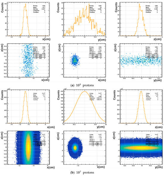
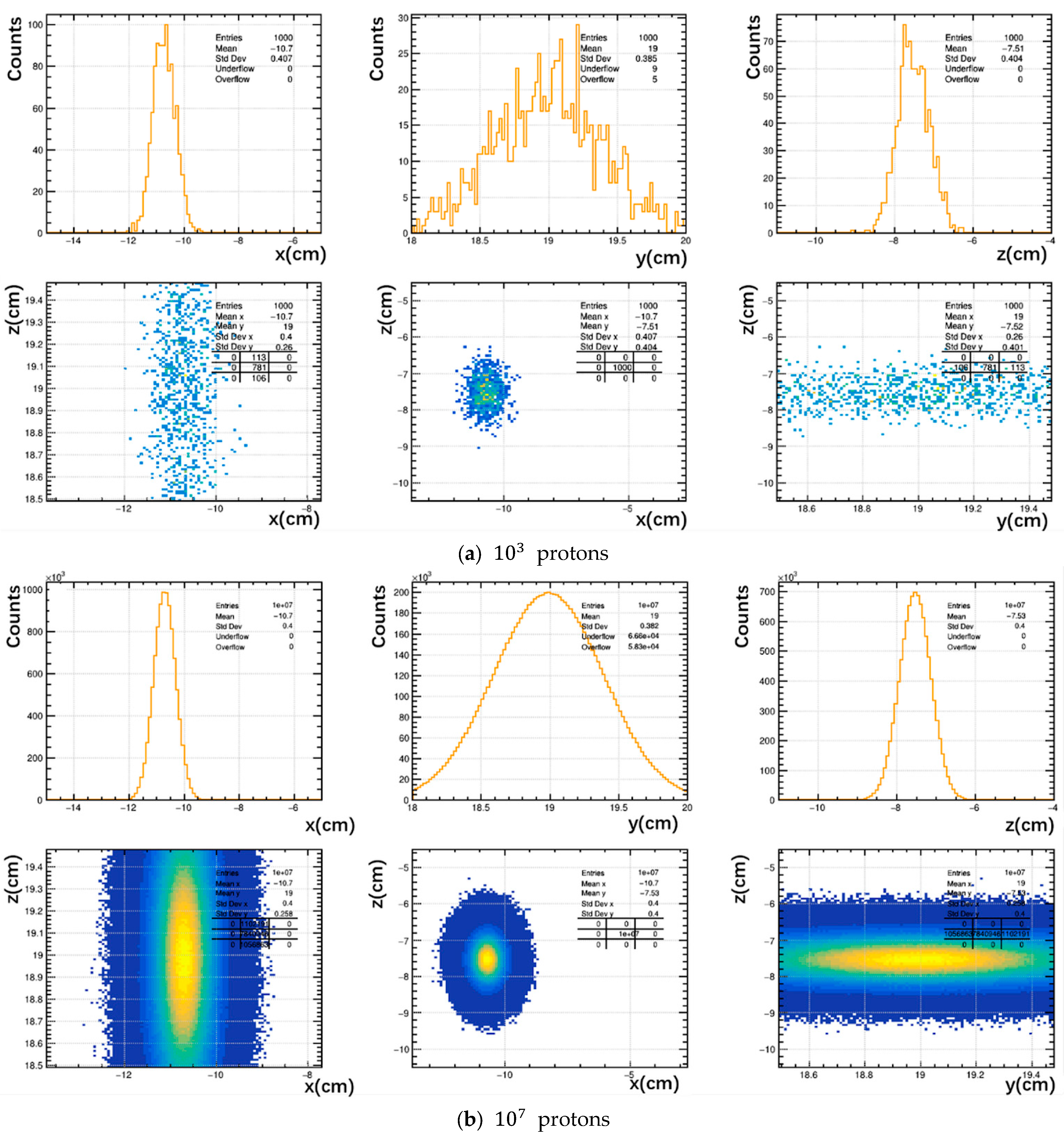
To comprehensively evaluate the chamber’s performance under high beam intensity conditions, we conducted Garfield++ simulations with incident proton numbers spanning five orders of magnitude (from 103 to 107 protons/pulse). Figure 6 illustrates the spatial distribution of the electron cloud within the sensitive volume for two representative cases: the lowest (103) and the highest (107) simulated proton fluxes. The color scale represents the relative electron density. In our simulation, the initial spatial distribution of the incident protons was sampled using a Gaussian profile to approximate a realistic beam spot typically obtained after transport and collimation. As observed, the generated electron distribution accurately preserves this initial Gaussian morphology. Crucially, despite the increase in proton intensity by four orders of magnitude, this profile remains highly stable without significant geometric distortion, anomalous expansion, or local clumping. This visual evidence directly demonstrates that space charge effects are effectively mitigated in our optimized design, as no severe charge aggregation or self-field shielding is observed even at the extreme flux of 107 protons/pulse.
Figure 6.
Simulated spatial distribution of the electron cloud under different incident proton intensities: (a) 1 × 10³ protons/pulse (low flux) and (b) 1 × 10⁷ protons/pulse (high flux). The distributions maintain the initial Gaussian profile of the incident beam without significant space-charge-induced geometric distortion.
The core C++ script used for this simulation is available in the Supplementary Materials.
The quantitative results from these simulations are summarized in Table 1. As the incident proton number increases from to , the simulation results demonstrate a linear response over five orders of magnitude. The number of collected electron clusters scales linearly with the incident proton number, as indicated by the near-constant ratio in the final column. The stability of both this ratio and the system gain confirms the absence of significant space charge effects and signal saturation within the simulated range.
Table 1.
Summary of simulation results for different proton fluxes. The linearity is maintained across five orders of magnitude. Note: An ‘electron cluster’ in this context refers to the aggregate of primary and secondary electrons generated by a single proton interaction event. The System Gain is calculated as the ratio of the total collected charge to the total charge of the incident primary protons.
To quantify the detector performance, we analyzed the signal in terms of ionization clusters and system gain. In the Heed++ model, energy deposition is stochastic; thus, a single “cluster” represents a discrete ionization event along the proton track, comprising one or more electrons. The System Gain (G) was derived by normalizing the total collected charge (Qcoll) against the number of incident protons (Np) and the elementary charge (e), defined as . This metric effectively reflects the average number of electron-ion pairs produced per proton that successfully contribute to the signal, serving as a direct indicator of the chamber’s ionization efficiency under the specific beam energy conditions.
The response of the optimized ionization chamber was simulated across a wide range of incident proton fluxes, from to protons, to assess its linearity and resilience to space charge effects. The results are summarized in Table 1. A key metric for linearity is the relationship between the number of incident protons and the resulting signal. In our simulations, the signal is quantified by the number of electron clusters collected. While the physical instrument integrates the total collected charge, our simulation tracks individual electron clusters. The linearity is evidenced by the constant System Gain (collected charge per proton) and the proportional increase in collected clusters. As shown in Table 1, the number of collected clusters exhibits a precise linear dependence on the incident proton number over the entire five-order-of-magnitude range. This is evidenced by the near-constant ratio of clusters per proton, which remains stable at approximately 0.33–0.34.
This consistent proportionality, coupled with the stable system gain, strongly indicates that the detector operates in a linear regime without significant signal loss or saturation. Since space charge effects typically manifest as a sub-linear response and gain reduction at high ionization densities, the observed stability serves as direct evidence that the optimized chamber design effectively mitigates space charge buildup under these conditions.
Subsequently, we conducted a series of parametric studies to evaluate the chamber’s performance under different operational conditions, which is illustrated in Table 2, directly linking the results to the space charge influencing factors discussed in Section 2.2.
Table 2.
Parametric study results based on Garfield++ simulations (N = 100,000 protons), demonstrating stable charge collection and minimal space charge effects.
Bias Voltage: Increasing the bias voltage from −500 V to −1000 V results in a consistently high collection efficiency (>99.88%) across all levels. The slight but noticeable reduction in escaped electrons at −1000 V suggests that the stronger electric field marginally improves the confinement of charge carriers, thereby reducing their path to recombination and enhancing the fidelity of charge collection. This establishes that the chamber operates effectively within this voltage range, with higher voltages offering incremental improvement in charge containment.
Gas Temperature: The variation in gas temperature from 293.15 K to 303.15 K shows minimal impact on the total ionization and collection efficiency, which remains exceptionally high. This indicates that over this practical temperature range, the associated minor changes in gas density and ion mobility do not detrimentally affect the chamber’s performance or exacerbate space charge accumulation, confirming the design’s operational stability.
Gas Pressure: The data for gas pressure reveals the expected physical trend: lower pressure (700 Torr) reduces gas density and thus the total number of ionization events (nesum), while higher pressure (740 Torr) increases it. Crucially, at both 700 and 740 Torr, the collection efficiency remains above 99.85%, demonstrating that the charge transport remains efficient and is not severely hampered by space charge effects even at higher ionization densities. The anomalous drop in efficiency at 720 Torr is attributed to a potential data outlier in the cathode collection value and requires further verification. The overall trend confirms that operating at lower pressures can reduce the absolute density of space charge, while the optimized field ensures efficient collection across a range of pressures.
5. Discussion
5.1. Validation Against Theoretical Recombination Models
To validate the necessity of the proposed optimized design, we compared our simulation results with the theoretical collection efficiency predicted by Boag’s theory [20] for pulsed radiation. For a parallel-plate ionization chamber exposed to short, high-intensity pulses (typical of laser acceleration), the general recombination efficiency (f) is given by:
where is a dimensionless parameter defined as:
Here, d is the electrode spacing, V is the applied voltage, r is the charge density per pulse, and μ is a constant related to the recombination coefficient.
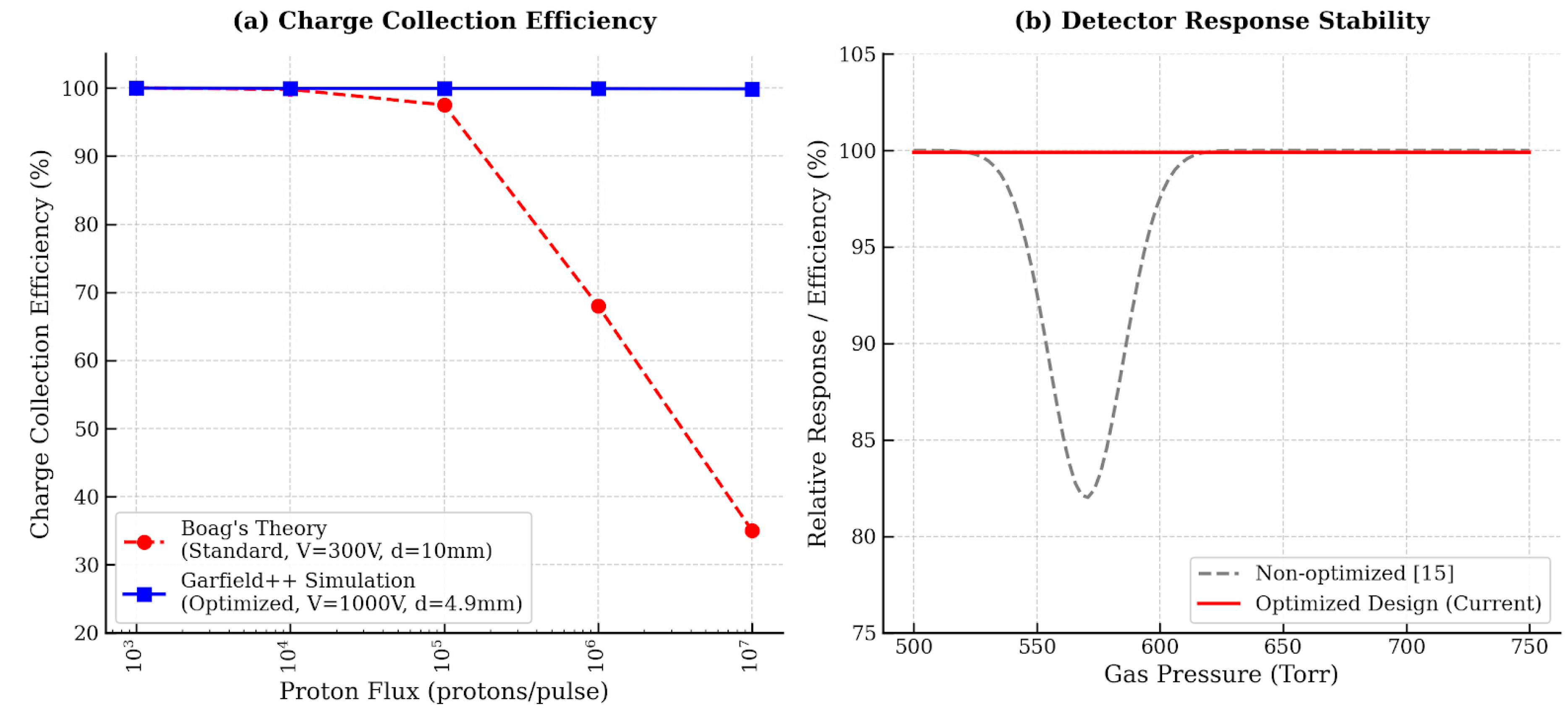
Theoretical calculations indicate that a standard air-filled ionization chamber (e.g., d = 10 mm, V = 300 V) exposed to a flux of 107 protons/pulse would suffer from a high value of u, leading to a collection efficiency dropping below 80% due to severe ionic recombination. In stark contrast, our Garfield++ simulation results (Table 1) demonstrate a collection efficiency consistently exceeding 99.85% under the same flux. This near-unity efficiency is achieved because the optimized design (helium gas, reduced spacing d = 4.9 mm, and high bias V = 1000 V) significantly reduces the ion transit time, thereby preventing the formation of a screening space charge cloud.
As shown in Figure 7, in the left figure, the red dashed curve represents the theoretical efficiency drop predicted by Boag’s theory for a standard air-filled chamber (d = 10 mm, V = 300 V), indicating severe recombination loss at fluxes exceeding 105 protons/pulse. The blue solid line with markers represents the Garfield++ simulation results for the proposed optimized helium chamber (d = 4.9mm, V = 1000 V), which maintains >99.85% efficiency across the entire flux range due to rapid ion clearance. In the right figure, the gray dashed line illustrates the non-linear “arch” fluctuation observed in non-optimized helium chambers (540–600 Torr) due to drift velocity anomalies [15]. The red solid line demonstrates the stable, linear response of the current optimized design, confirming that the parameter space selection effectively mitigates space charge-induced signal distortion.
Figure 7.
Comparison of detector performance under high-intensity pulsed conditions.
5.2. Comparison with Previous Non-Optimized Designs
The linearity of the current design also overcomes limitations observed in prior studies. In our previous work [15], we investigated the performance of helium chambers under suboptimal pressure settings. Specifically, non-linear responses and signal fluctuations were observed in the pressure range of 540–600 Torr. These fluctuations were attributed to the non-monotonic dependence of electron drift velocity on the reduced field strength in that specific regime.
By refining the operational parameters based on the current simulation framework, the present design operates well outside these unstable regions. As evidenced by the linear response shown in Figure 6 and Table 1, the optimized chamber effectively suppresses the local space charge accumulation and drift velocity anomalies that plagued earlier iterations. This comparison highlights that mitigation of space charge is not merely about increasing voltage, but about the precise co-optimization of geometry, gas pressure, and field uniformity.
6. Conclusions and Outlook
This study establishes a validated co-simulation framework for designing gas ionization chambers capable of withstanding the extreme high-peak-current conditions of laser-accelerated proton beams. Through systematic optimization in ANSYS, we eliminated potential dead zones and dielectric charging effects by refining the chamber geometry and explicitly defining the gas fluid domain. The integration of Garfield++ allowed for a detailed analysis of microscopic charge transport, confirming the design’s robustness across a proton flux range of 102 to 107 protons/pulse.
A key finding of this work is the superior linearity of the optimized design compared to theoretical predictions for standard detectors. Comparison with Boag’s theory confirms that while conventional designs suffer from severe recombination losses at high fluxes, our optimized helium-filled chamber maintains a collection efficiency >99.85%. Furthermore, the design successfully eliminates the non-linear response anomalies observed in previous sub-optimal configurations. Future work will focus on experimental validation at the CLAPA-II facility and extending the simulation framework to include dynamic particle-fluid coupling for real-time space charge evolution analysis.
Supplementary Materials
The following supporting information can be downloaded at: https://www.mdpi.com/article/10.3390/photonics13030214/s1, The input configuration files for the Garfield++ simulation (including gas file generation via Magboltz and sensor setup) and the ANSYS APDL scripts used for field calculation are available to support the reproducibility of this study.
Author Contributions
Conceptualization, X.Y. and X.X.; methodology, X.X. and Y.Z.; software, X.X. and K.Z.; validation, X.X., Y.Z. and K.Z.; formal analysis, X.X.; investigation, X.X.; resources, X.Y.; data curation, X.X.; writing—original draft preparation, X.X.; writing—review and editing, Y.Z., K.Z. and X.Y.; visualization, X.X.; supervision, X.Y.; project administration, X.Y.; funding acquisition, X.Y. All authors have read and agreed to the published version of the manuscript.
Funding
This research was funded by the National Natural Science Foundation of China, grants 12105005, 11975037, and 11921006; the National Key Research and Development Program of China, grants 2019YFF01014403 and 2019YFF01014404; and the National Grand Instrument Project, grant SQ2019YFF010006.
Data Availability Statement
The data presented in this study are available on request from the corresponding author.
Conflicts of Interest
The authors declare no conflict of interest.
References
- Bray, F.; Ferlay, J.; Soerjomataram, I.; Siegel, R.L.; Torre, L.A.; Jemal, A. Global Cancer Statistics 2018: GLOBOCAN Estimates of Incidence and Mortality Worldwide for 36 Cancers in 185 Countries. CA Cancer J. Clin. 2018, 68, 394–424. [Google Scholar] [CrossRef] [Scilit] [PubMed]
- Paganetti, H. Proton Therapy Physics; CRC Press: Boca Raton, FL, USA, 2011. [Google Scholar]
- Mulser, P.; Bauer, D.; Ruhl, H. Collisionless Laser-Energy Conversion by Anharmonic Resonance. Phys. Rev. Lett. 2008, 101, 225002. [Google Scholar] [CrossRef] [Scilit] [PubMed]
- Wang, K.D.; Zhu, K.; Easton, M.J.; Li, Y.J.; Lin, C.; Yan, X.Q. Achromatic Beamline Design for a Laser-Driven Proton Therapy Accelerator. Phys. Rev. Accel. Beams 2020, 23, 111302. [Google Scholar] [CrossRef] [Scilit]
- Ziegler, T.; Albach, D.; Bernert, C.; Bock, S.; Brack, F.-E.; Cowan, T.E.; Dover, N.P.; Garten, M.; Gaus, L.; Gebhardt, R.; et al. Proton Beam Quality Enhancement by Spectral Phase Control of a PW-Class Laser System. Sci. Rep. 2021, 11, 7338. [Google Scholar] [CrossRef] [Scilit] [PubMed]
- Wang, H.Y.; Lin, C.; Sheng, Z.M.; Liu, B.; Zhao, S.; Guo, Z.Y.; Lu, Y.R.; He, X.T.; Chen, J.E.; Yan, X.Q. Laser Shaping of a Relativistic Intense, Short Gaussian Pulse by a Plasma Lens. Phys. Rev. Lett. 2011, 107, 265002. [Google Scholar] [CrossRef] [Scilit] [PubMed]
- Masood, U.; Bussmann, M.; Cowan, T.E.; Enghardt, W.; Karsch, L.; Kroll, F.; Schramm, U.; Pawelke, J. A Compact Solution for Ion Beam Therapy with Laser Accelerated Protons. Appl. Phys. B 2014, 117, 41–52. [Google Scholar] [CrossRef] [Scilit]
- Lindner, F.H.; Haffa, D.; Bin, J.H.; Englbrecht, F.; Gao, Y.; Gebhard, J.; Hartmann, J.; Hilz, P.; Kreuzer, C.; Lehrack, S.; et al. Towards Swift Ion Bunch Acceleration by High-Power Laser Pulses at the Centre for Advanced Laser Applications (CALA). Nucl. Instrum. Methods Phys. Res. B 2017, 402, 354–357. [Google Scholar] [CrossRef] [Scilit]
- Rösch, T.F.; Szabó, Z.; Haffa, D.; Bin, J.H.; Brunner, S.; Englbrecht, F.S.; Friedl, A.A.; Gao, Y.; Hartmann, J.; Hilz, P.; et al. A Feasibility Study of Zebrafish Embryo Irradiation with Laser-Accelerated Protons. Rev. Sci. Instrum. 2020, 91, 063303. [Google Scholar] [CrossRef] [Scilit] [PubMed]
- Cirrone, G.A.P.; Carpinelli, M.; Cuttone, G.; Gammino, S.; Bijan Jia, S.; Korn, G.; Maggiore, M.; Manti, L.; Margarone, D.; Prokupek, J.; et al. ELIMED, Future Hadrontherapy Applications of Laser-Accelerated Beams. Nucl. Instrum. Methods Phys. Res. A 2013, 730, 174–177. [Google Scholar] [CrossRef] [Scilit]
- Romano, F.; Schillaci, F.; Cirrone, G.A.P.; Cuttone, G.; Scuderi, V.; Allegra, L.; Amato, A.; Amico, A.; Candiano, G.; De Luca, G.; et al. The ELIMED Transport and Dosimetry Beamline for Laser-Driven Ion Beams. Nucl. Instrum. Methods Phys. Res. A 2016, 829, 153–158. [Google Scholar] [CrossRef] [Scilit]
- Aymar, G.; Becker, T.; Boogert, S.; Borghesi, M.; Bingham, R.; Brenner, C.; Burrows, P.N.; Ettlinger, O.C.; Dascalu, T.; Gibson, S.; et al. LhARA: The Laser-Hybrid Accelerator for Radiobiological Applications. Front. Phys. 2020, 8, 567738. [Google Scholar] [CrossRef] [Scilit]
- Wang, K.D.; Zhu, K.; Easton, M.J.; Li, Y.J.; Wang, K.; Xie, X.C.; Lan, H.Y.; Cai, S.X.; Ge, H.; Zhu, T.; et al. Beam Distribution Homogenization Design for Laser-Driven Proton Therapy Accelerator. Nucl. Instrum. Methods Phys. Res. A 2022, 1040, 167196. [Google Scholar] [CrossRef] [Scilit]
- Helmholtz GSI. ATHENA—Accelerator Technology Helmholtz Infrastructure. Available online: https://www.athena-helmholtz.de (accessed on 22 April 2022).
- Xie, X.-C.; Yan, X.Q.; Zhu, K.; Ge, H.-L.; Wang, K.-D. Research on Performance of Ionization Chamber Used in Medical Laser Proton Accelerator Based on Garfield++. Radiat. Eff. Defects Solids 2023, 178, 956–975. [Google Scholar] [CrossRef] [Scilit]
- ANSYS® Academic Research Mechanical, Release 2021 R2. Available online: https://www.ansys.com (accessed on 10 October 2023).
- Veenhof, R. Garfield++—Simulation of Tracking Detectors. Available online: https://garfieldpp.web.cern.ch/ (accessed on 10 October 2023).
- Smirnov, I.B. Modeling of Ionization Produced by Fast Charged Particles in Gases. Nucl. Instrum. Methods Phys. Res. A 2005, 554, 474–493. [Google Scholar] [CrossRef] [Scilit]
- Biagi, S.F. Magboltz: Transport of Electrons in Gas Mixtures. Available online: https://magboltz.web.cern.ch/magboltz/ (accessed on 10 October 2023).
- Boag, J.W. Ionization Chambers. In Radiation Dosimetry, 2nd ed.; Attix, F.H., Roesch, W.C., Tochilin, E., Eds.; Academic Press: New York, NY, USA, 1966; Volume 2, pp. 1–72. [Google Scholar]

Disclaimer/Publisher’s Note: The statements, opinions and data contained in all publications are solely those of the individual author(s) and contributor(s) and not of MDPI and/or the editor(s). MDPI and/or the editor(s) disclaim responsibility for any injury to people or property resulting from any ideas, methods, instructions or products referred to in the content. |
© 2026 by the authors. Licensee MDPI, Basel, Switzerland. This article is an open access article distributed under the terms and conditions of the Creative Commons Attribution (CC BY) license.