


Abstract
This paper deals with design of permanent magnet synchronous generators (PMSG) for diesel engine generators. The PMSG is required to reduce the total harmonic distortion (THD) reduction of the induced electromotive force (EMF) for the enhancement of power quality. In this paper, a design method is proposed to reduce the THD of the induced EMF for power quality enhancement in the PMSG. First, the selection process for the number of poles and slots is described. Second, the rotor shape design is proposed using an eccentric curve and slit shape. Based on the results of the first process, the optimal rotor shape is selected to achieve the additional THD reduction of the induced EMF. Finally, the performance for the optimal rotor shape is verified through a 2-dimensional finite element analysis (2D FEA) and prototype.
1. Introduction
As the demands of high efficiency for electric machines increase, synchronous motors for diesel engine generators have been converted from wound field types to permanent magnet types. In order to increase the high-quality electric power of permanent magnet synchronous generators (PMSGs), an inverter is widely used instead of a separate exciter [1,2].
Compared to a wound field type generator, the PMSG also has a key strength in physical size reduction. Moreover, PMSGs produce higher quality output than the wound field type generator because they control the voltage and frequency using an inverter. However, loss and vibration are inevitable if the combination of the number of poles and slots is not selected carefully [3]. Furthermore, the power quality of the generator is affected by the total harmonic distortion (THD) of the induced electromotive force (EMF) at the no load and load drive for the generator drive conditions.
Generally, the induced EMF THD increases more at the load than at no-load for the drive conditions of the generator. This is because the wave form of the magnetic flux density in the air gap is distorted due to the influence of the armature reaction [4]. Therefore, it is an essential design factor to reduce the induced EMF THD at the load drive in the generator design. Furthermore, if the power factor (PF) in the PMSG is less than one, the induced EMF THD at the load drive increases. This reduced PF deteriorates the power quality of the PMSG. In order to reduce the induced EMF THD, a rotor shape design is commonly used.
Eccentricity and pole angle are key design parameters in the rotor shape design. However, eccentricity is generally applied to enhance the performance in three types of permanent magnet electric machines. First, the spoke-type machine deals with the eccentricity to reduce the induced EMF THD and torque ripple for the cost reduction of the rare earth magnet [5]. Second, the surface permanent magnet machine (SPM) also deals with eccentricity, mainly to reduce cogging torque for automotive EPS (electric power steering) systems [6,7]. The reduction of cogging torque is the most essential quality factor to enhance steering feeling. Finally, the internal permanent magnet (IPM) also deals with eccentricity to reduce not only the torque ripple and induced EMF THD, but also iron loss [8,9]. The reduction of iron loss is a key design factor in the IPM-type machine to improve efficiency at high speed, such as in electric vehicles (EVs) [10,11,12].
For this reason, it can be concluded that most previous research mainly focused on eccentricity to reduce the induced EMF THD and torque ripple. Accordingly, eccentricity is considerably effective at reducing induced EMF THD. However, eccentricity has two weaknesses. One is the increase of THD at the load drive, while the other is the reduction of induced EMF magnitude. Therefore, it is necessary to overcome these weaknesses resulting from the eccentricity.
This paper proposes a design method to reduce the induced EMF THD at the load drive and increase the magnitude of induced EMF for power quality enhancement in PMSGs. First, the selection process of the number of poles and slots for the initial design is described. Second, the rotor shape design is proposed using the eccentric curve and slit shape. Based on the results of this first process, the optimal rotor shape is designed to achieve additional THD reduction and increase EMF magnitude. Finally, the performance for the final design is verified through 2D finite element analysis (FEA) and experimentation.
2. Proposed Design Process of PMSG
2.1. Selection of Pole and Slot Number
This paper deals with the PMSG for a diesel engine. The rated voltage and frequency was 380 V, with a root mean value for line-to-line, and 60 Hz, respectively. The rated output power was 78 kW and the cooling type was air-forced cooling. The pole number four was selected to meet the 60 Hz of output power frequency by considering the rated rotational speed (1800 rpm) of the diesel engine. The design specifications are shown in Table 1.
Table 1.
Design specifications.
The permanent magnet in the PMSG is a N42SH and its residual flux density is Br = 1.2 [T] at 100 °C. In this paper, the Br value was used to analyze the PMSG for the 2D FEA.
Generally, the size of an electric machine is determined based on the design specifications. The sizing parameters are one of the main methods to decide the size of an electric machine. In this paper, the sizing parameters were used to decide the size of the PMSG. The sizing factors are the torque per rotor unit volume (TRV) and the shape ratio (SR), as expressed in Equations (1) and (2) [13,14].
In (1) and (2), Trated, Dr, and Lstk represent the rated torque, external diameter of the rotor, and the stack length of the stator and rotor, respectively. In this paper, the values of the TRV and SR in sizing are referred to as 30 kNm/m3 and 2.37, respectively [13,14]. Table 1 lists the design specification, including the values of TRV and SR.
The stack length and diameter of the rotor were calculated using (1) and (2), as shown Table 1. In this paper, the layout type of the magnet in the PMSG is an IPM (internal permanent magnet) to prevent the magnet from spattering in the rotor. The induced EMF THD for the generator differs from the slot number and winding type.
Fractional slot winding, one of the winding types, is characterized by a high winding coefficient and a low induced EMF THD. In factional slot winding, the high winding coefficient refers to the high fundamental component value of the induced EMF [15]. In order to reduce the induced EMF THD using fractional slot winding, the selection process for the slot number was carried out as described below.
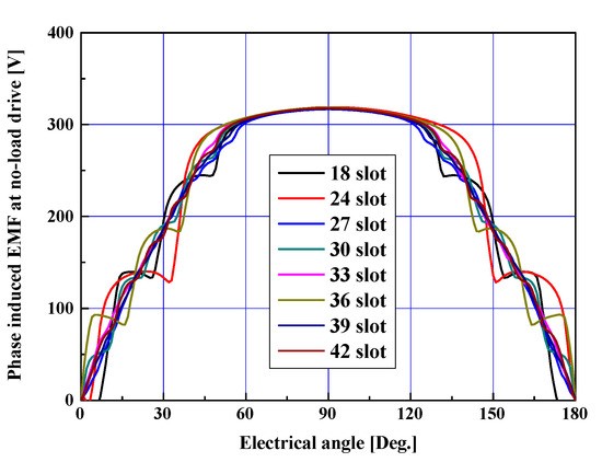
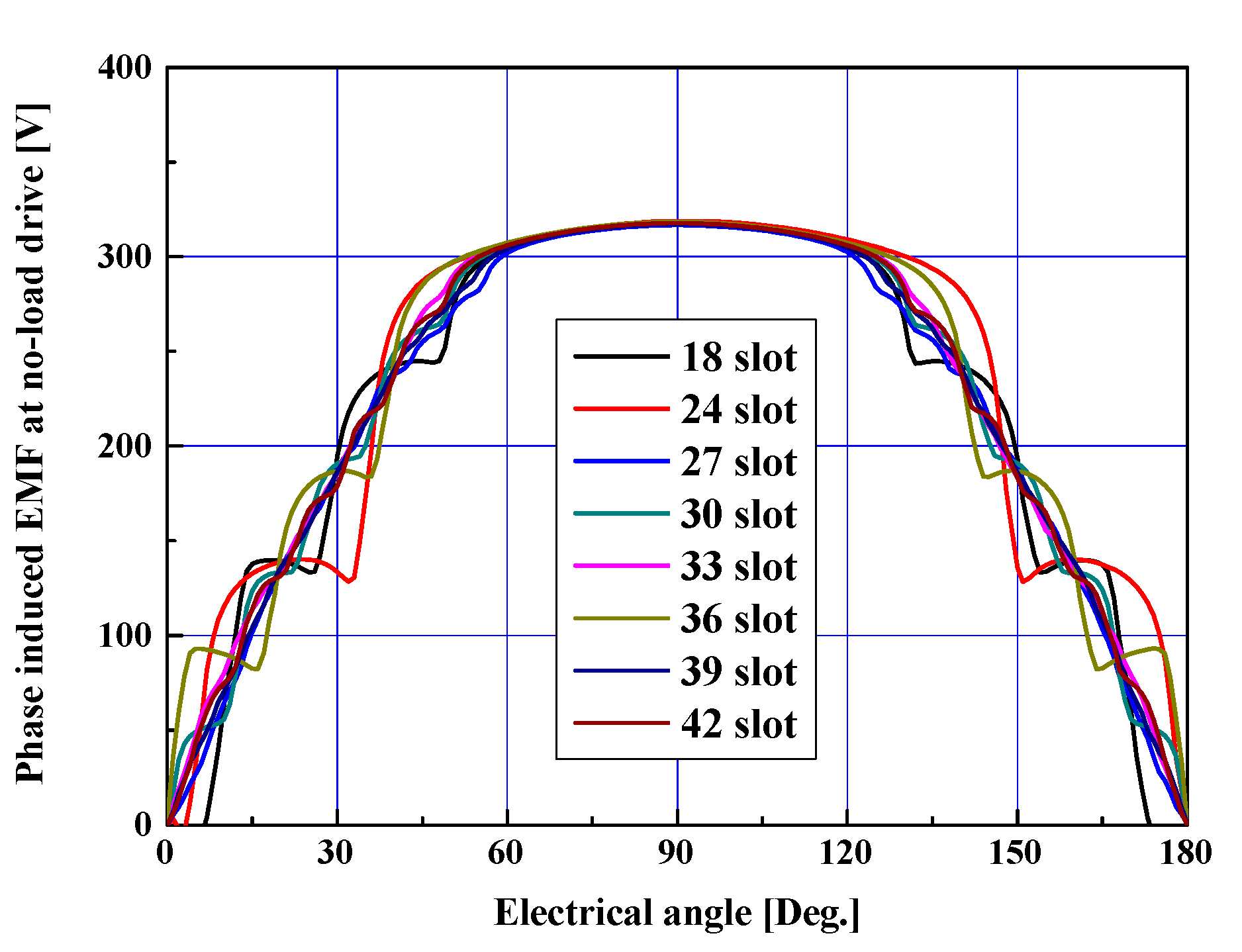
Figure 1 shows the wave form of the induced EMF at the no-load drive of 1800 rpm with four poles. The wave form of the induced EMF at the no-load drive was analyzed by space harmonic analysis, one of the analytical methods.
Figure 1.
Wave form of the induced EMF at no-load drive according to the slot number.
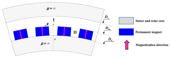
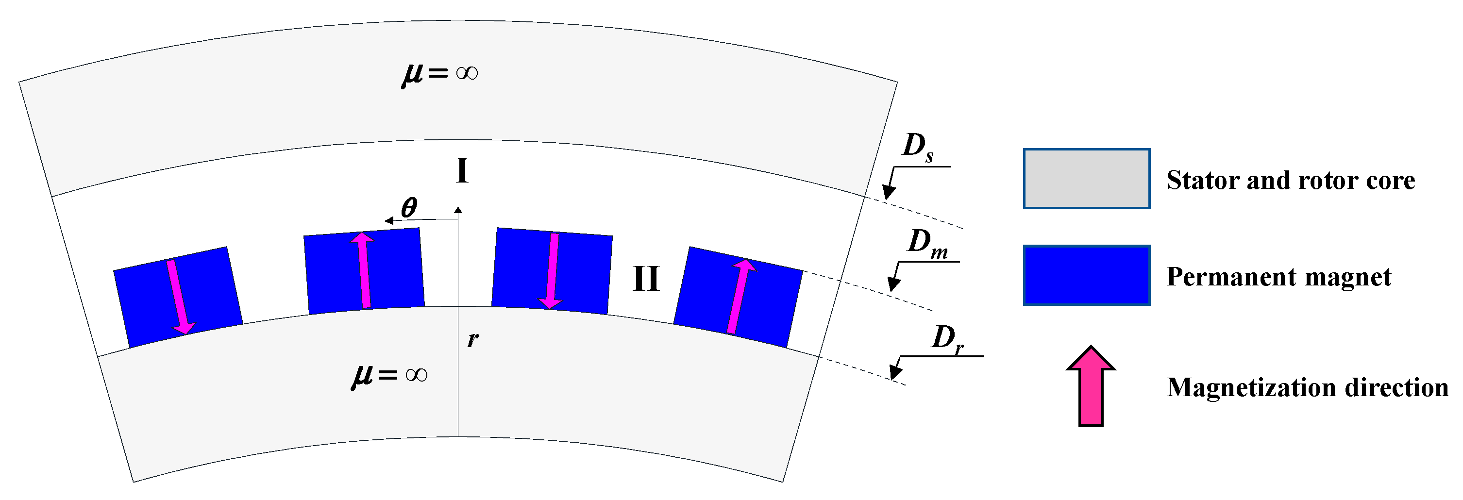
The space harmonic analysis calculates the characteristics of the electric machine by modelling the flux density of the air gap with the mathematical method. The strength of the space harmonic analysis is to shorten the analysis time when compared to numerical methods, such as 2D FEA. Figure 2 shows the simplified model of the PMSG with polar coordinates for space harmonic analysis. In Figure 2, Ds and Dm represent the internal radius of the stator and the external radius of the magnet, respectively. However, the following assumptions are required [16]:
Figure 2.
Simplified model for space harmonic analysis.
- The end effect is neglected;
- Permeability of the cores in the stator and rotor µ is infinite;
- The tooth tip of the slot open in the stator is neglected;
- The permanent magnet has a constant periodicity in θ direction.
Region I and II in Figure 2 are the region of the air gap and the permanent magnet. In region I, the magnetic scalar potential φ is governed by Laplace’s equation and the distribution of φ can be expressed by Equation (3) [16].
For region II, the φ is governed by Poisson’s equation and the distribution of φ can be expressed by Equation (4). In (4), Mr and µr refer to the magnetization in radial direction and the relative recoil permeability of the permanent magnet, respectively [16].
Therefore, the wave form of the induced EMF, including the air gap flux density and flux linkage, can be analyzed by Equations (3) and (4) with Figure 1 [17].
In this paper, the space harmonic analysis is used to confirm the quick results of the induced EMF THD in the initial design step for the selection of the pole and slot number.
Table 2 shows the fundamental root mean square (rms) and THD for the induced EMF, and the radial force order at the no-load drive with four poles according to the slot number, as shown in Figure 1. The fundamental components were calculated by using the harmonic order analysis based on the wave form in Figure 1. In Table 2, q refers to the slot number per phase per pole. The radial harmonic order, rλ, was calculated using Equation (4). In Table 2, the induced EMF THD, whose values were less than 10%, had slot numbers 18, 27, 30, 33, 39, and 42. Therefore, these slot numbers corresponded to fractional slot winding.
Table 2.
Phase induced EMF and radial force order according to the slot number.
However, these fractional slot windings have an inevitable weakness: vulnerability to vibration. The magnetic force in the radial direction, occurring in the air gap, causes these vibrations [18].
The magnetic force in the radial direction also has fundamental and harmonic components. The deformation amount of the stator ∆d differs from the radial harmonic order rλ, the harmonic order of the magnetic force in the radial direction. The ∆d is inversely proportional to the 4th power of rλ approximately, as shown in Equation (5) [19].
Therefore, the lower the radial harmonic order, the larger the deformation amount of the stator. The maximum value of rλ in Table 2 was calculated using Equation (6). In (6), Ns and Np represent the slot number and pole number, respectively, while r refers to the space harmonic order for the space distribution of induced EMF in the rotor. As the distribution of the induced EMF can be approximated by a square wave form, r has an odd integer [19].
where r is an odd integer.
Based on these procedures, the possible slot number in Table 2 should meet the constraints which have low a THD and a high rλ among the fractional winding mentioned above. As a result, the candidate slot numbers were 18, 30, and 40. However, the final slot number selected was 18 to meet the fill factor ratio in Table 1 among the candidate slot numbers.
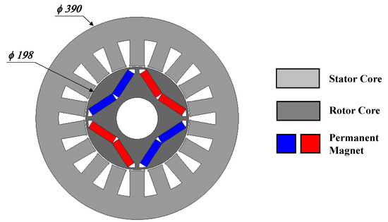
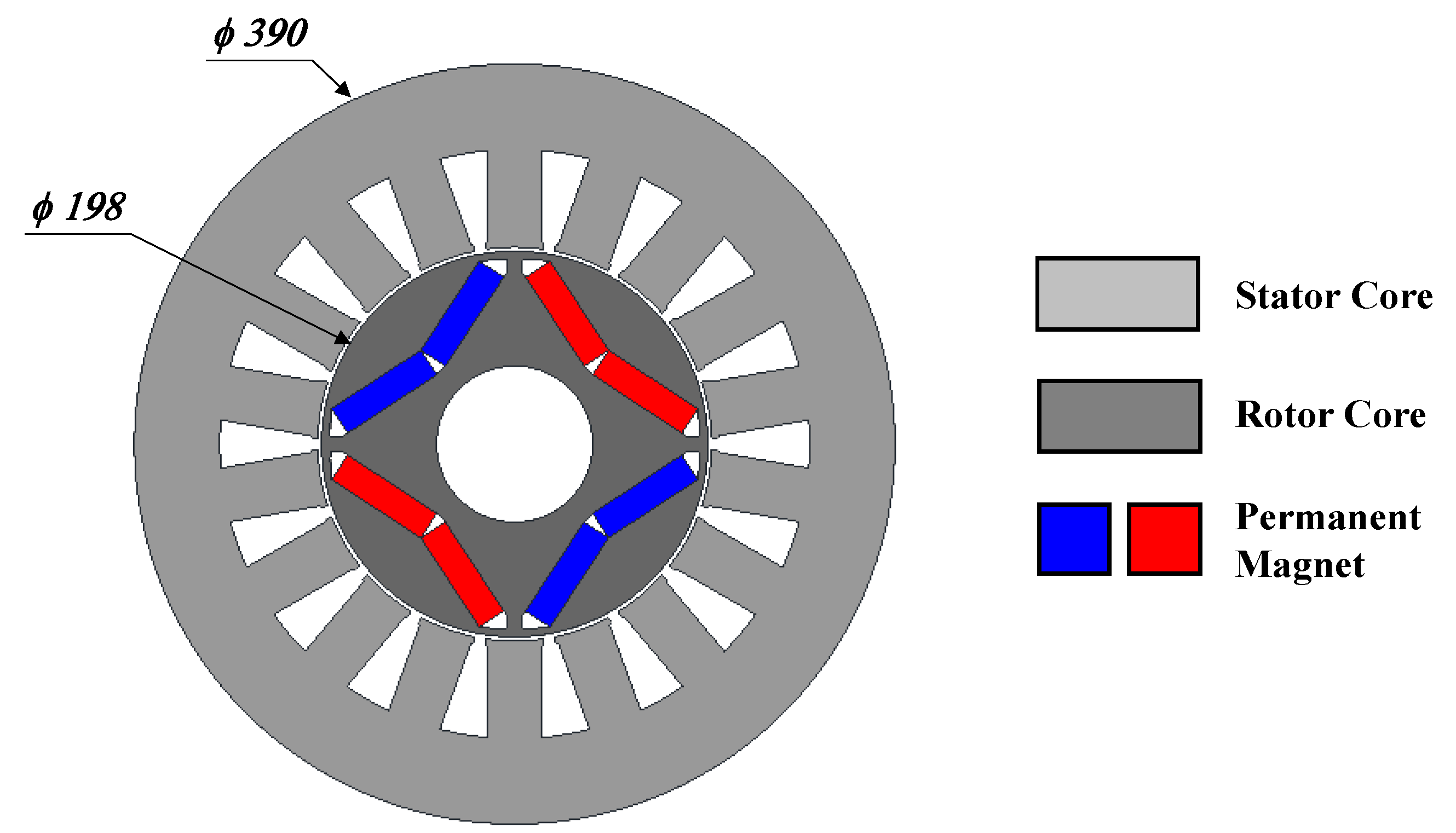
Figure 3 shows the initial design model with four poles and 18 slots. The 2D FEA was conducted to confirm the induced EMF for the initial design.
Figure 3.
Cross-sectional view of the initial design.
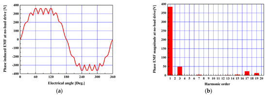
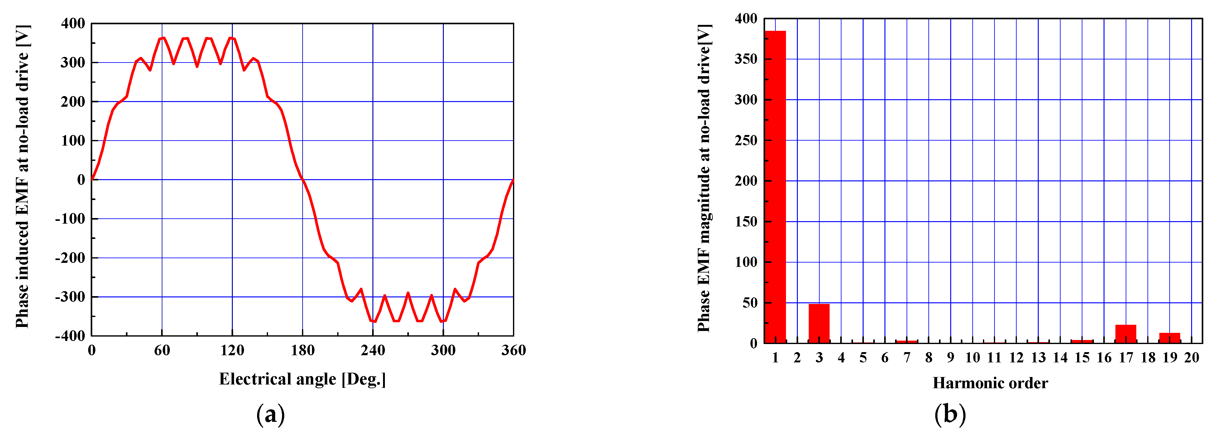
Figure 4a shows the wave form of the phase induced EMF at a no-load drive with 1800 rpm using 2D FEA. In Figure 4b, the 3rd order exists due to the slot open of the stator, which was not considered in the space harmonic analysis used in Figure 1 [16].
Figure 4.
Induced EMF at no-load drive for the initial design: (a) wave form, and (b) harmonic order.
2.2. Reduction Design of the Induced EMF THD
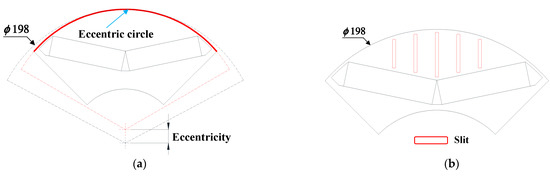
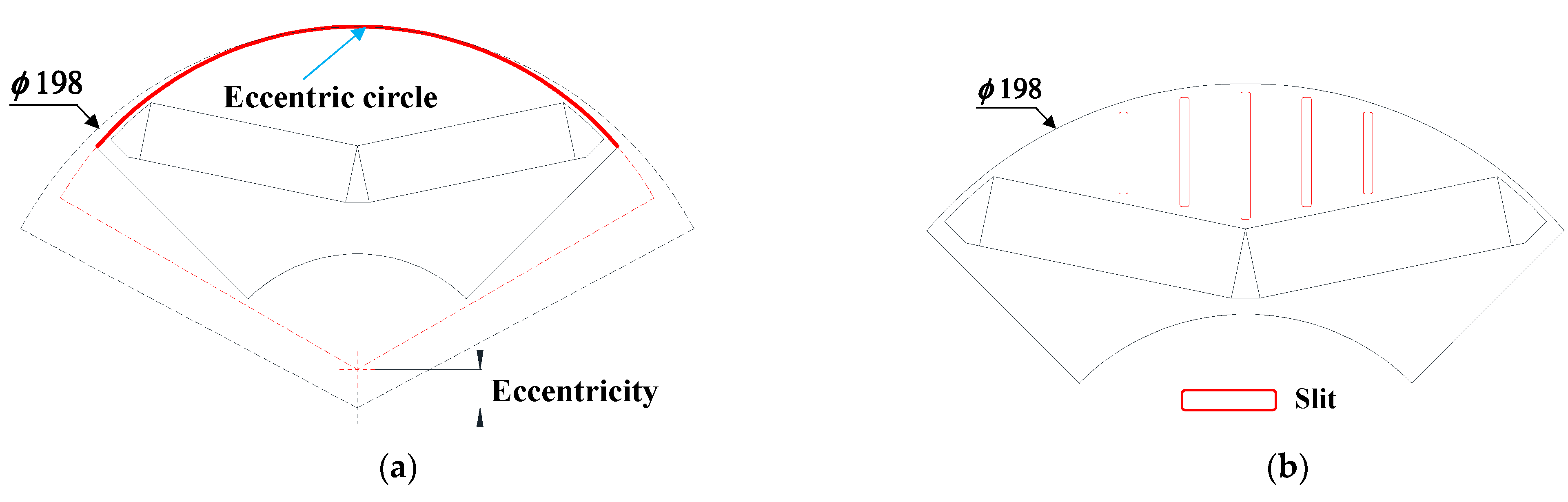
The rotor shape design was conducted to reduce the THD of the induced EMF in the initial design, as shown in Figure 3. In this paper, the shapes of eccentricity and slit are used in the rotor shape design of the PMSG. Generally, eccentricity in the rotor is one of the general methods used for reducing the THD of the induced EMF and torque ripple [5,6,7,8,9,10,11,12]. Figure 5a shows the eccentricity applied for the rotor based on the rotor diameter specified in Table 1. For the slit in Figure 5b, this was proposed to improve the wave form of the induced EMF so as to be a sinusoidal wave form.
Figure 5.
Proposed design in the rotor shape: (a) eccentricity, and (b) slit.
Therefore, this paper proposes two shapes in the rotor shape design. First, the eccentricity in the rotor shape is investigated to affect the magnitude and THD of the induced EMF wave form.
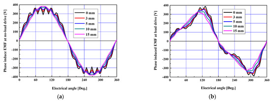
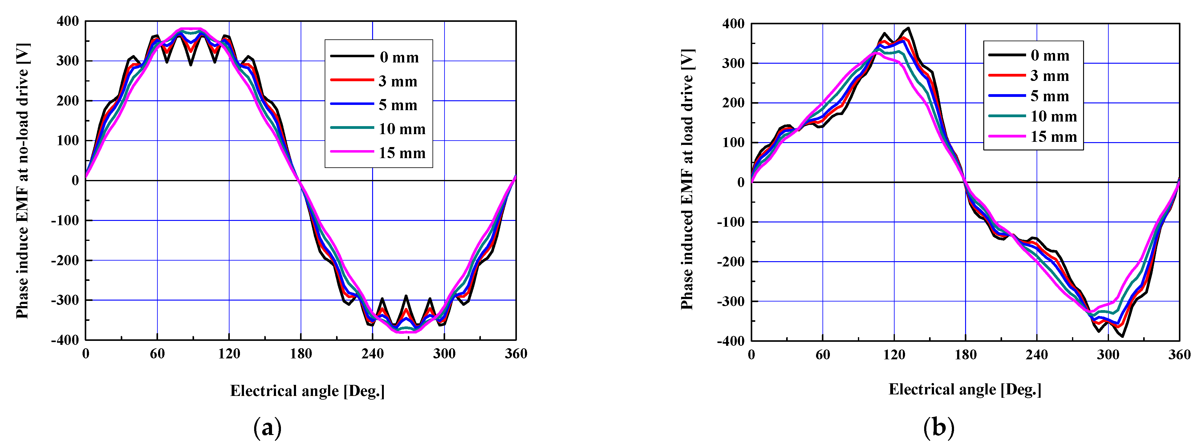
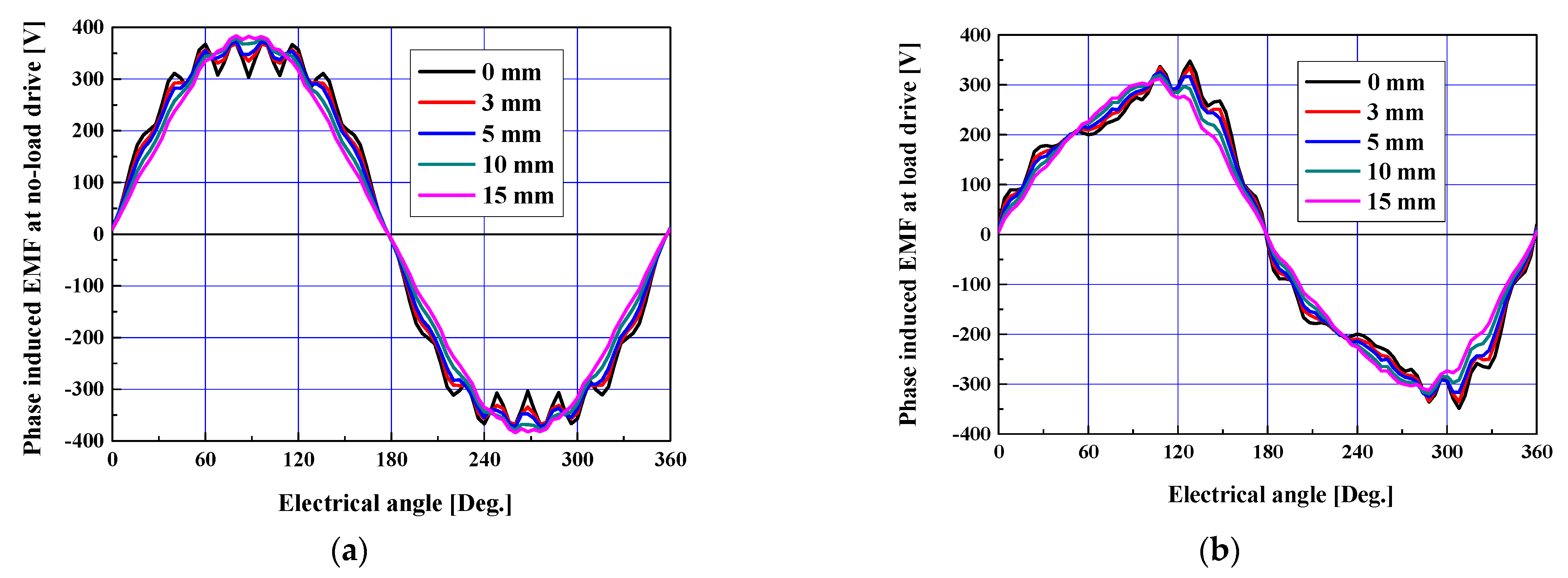
Figure 6 shows the wave form of the induced EMF at the no-load and load drives according to the eccentricity. The wave forms in Figure 6 were obtained using 2D FEA. As the eccentricity increased, the wave form came closer to becoming a sinusoidal wave form in both the no-load and load drives. In Figure 6b, the analysis conditions of the load drive show that the power was 78 kW and the PF (power factor) was 0.8. The wave form of the induced EMF is considerably distorted due to the armature reaction, as shown in Figure 6b [20].
Figure 6.
Wave form of the induced EMF according to the eccentricity: (a) no-load drive, and (b) load drive.
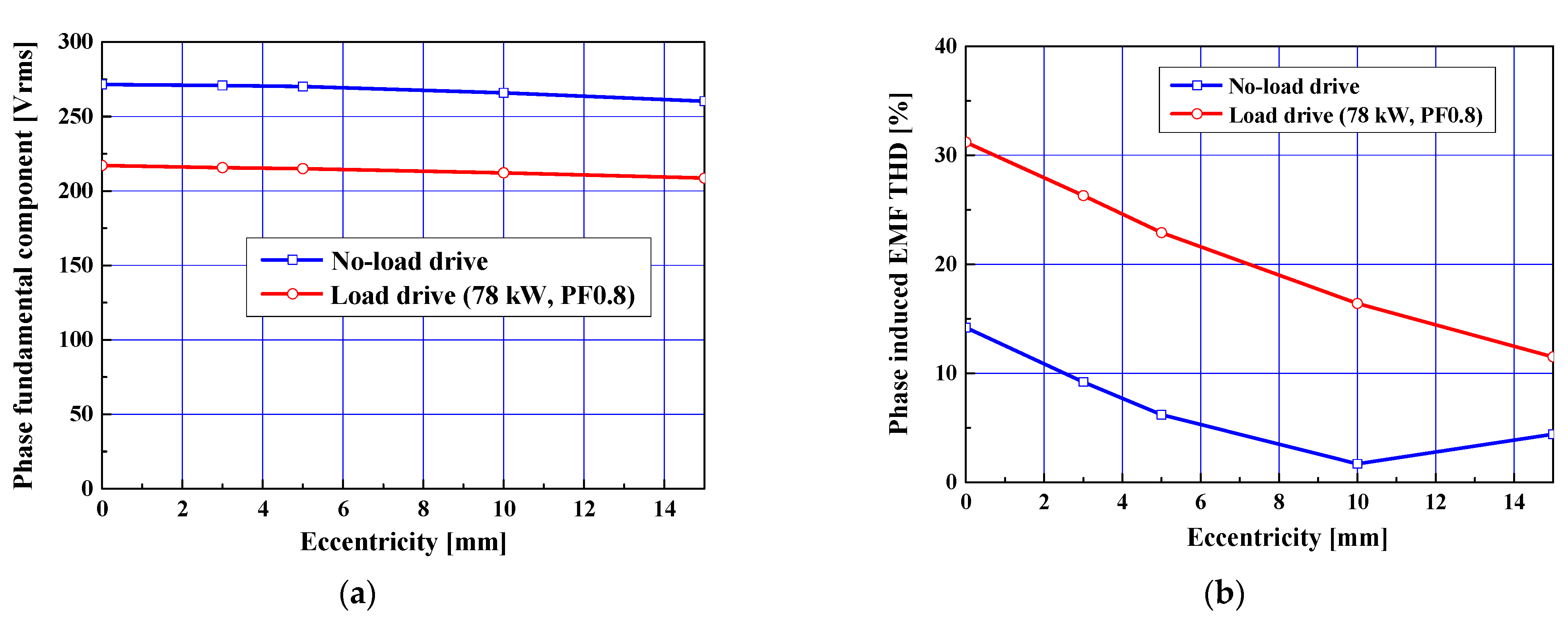
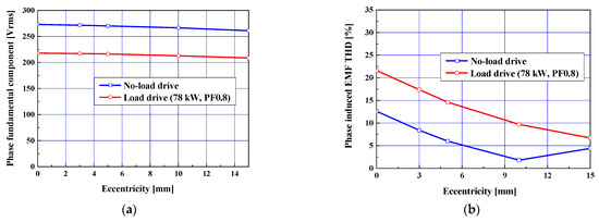
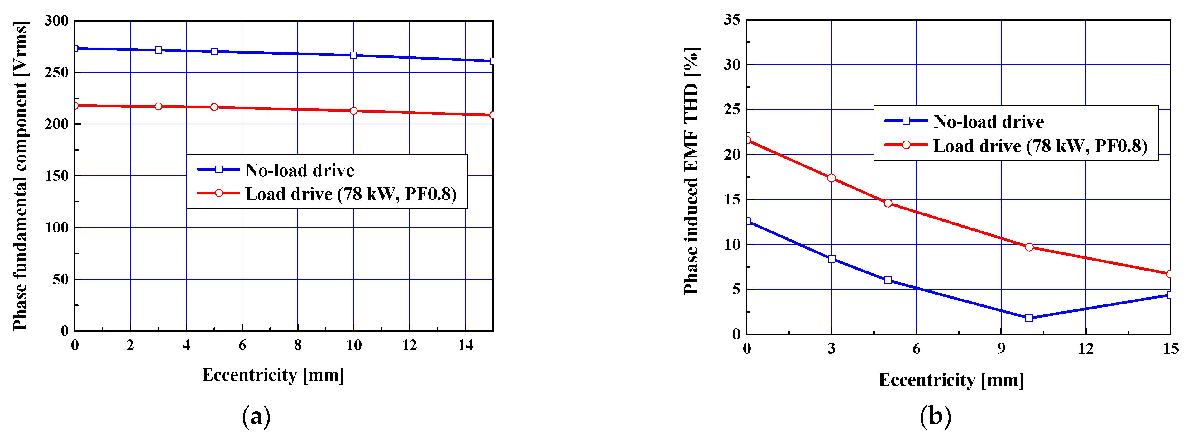
As the eccentricity increases in Figure 6, it was expected that this would reduce the fundamental component with the root mean (rms) value for the wave form of the induced EMF. The fundamental component with the rms value is denoted as the fundamental component below. Figure 7 shows the fundamental component and the THD of the induced EMF at the no-load and load drives according to the eccentricity. In Figure 7a, the fundamental components of the induced EMF at the no-load and load drives decreased. However, the change rates for the two fundamental components were 4.1% and 3.2%, respectively.
Figure 7.
Induced EMF at no-load and load drives according to the eccentricity: (a) fundamental component, and (b) THD.
The change rate means the percentage of the induced EMF for the two eccentricities was 0 and 15 mm. Accordingly, the change rates for the induced EMF were relatively small according to the eccentricity. In case of the induced EMF THD at the no-load and load drives, the induced EMF THD decreased as the eccentricity increased. However, in the case of the no-load drive, the THD had a minimum value at the eccentricity of 10 mm and then increased again.
Second, the other proposed design was a hybrid model, an eccentric shape including the slit shape of Figure 5b. Figure 8 and Figure 9 show the wave form and THD for the proposed model at the no-load and load drives. The wave forms in Figure 8 were obtained by 2D FEA. These figures correspond to Figure 6 and Figure 7, respectively. When applying the slit design, the eccentricity increased, and the wave forms of the induced EMF at the no-load and load drives moved closer to a sinusoidal wave form in a similar way to Figure 6.
Figure 8.
Wave form of the induced EMF according to the eccentricity with the slit: (a) no-load drive, and (b) load drive.
Figure 9.
Induced EMF at no-load and load drives according to the eccentricity with the slit: (a) fundamental component, and (b) THD.
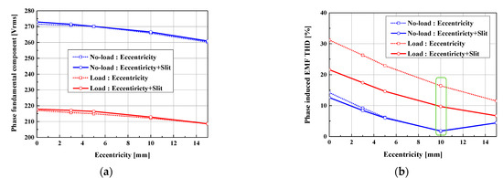
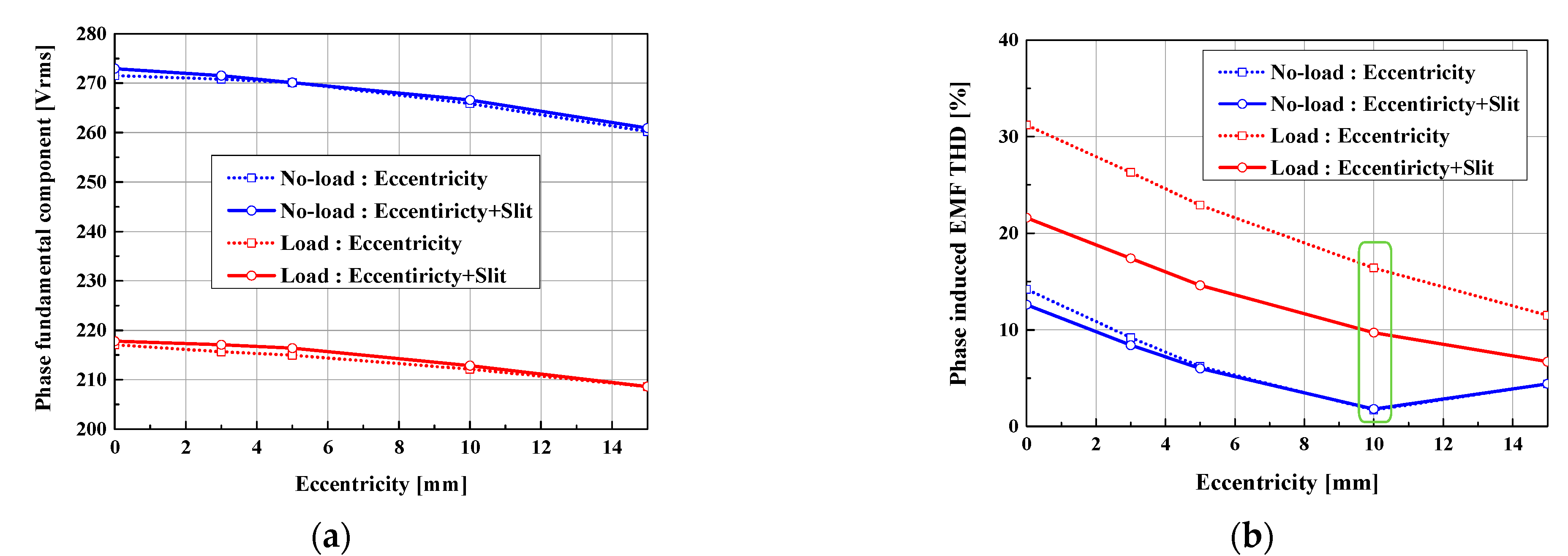
Figure 9 also shows the fundamental component and THD of the induced EMF at the no-load and load drives for the proposed design models used in Figure 5b. Figure 10 shows the summarized results of the fundamental component and the THD for the two proposed models in Figure 5. The fundamental components of the eccentricity model with the slit in Figure 10a are relatively higher than that of the eccentricity model according to the eccentricity at both the no-load and load drives.
Figure 10.
Comparison of the induced EMF at no-load and load drives for the two proposed models: (a) fundamental component, and (b) THD.
For the induced EMF THD in Figure 10b, the eccentricity model with the slit was also relatively lower than that of the eccentricity model at both the no-load and load drives. In the load drive, the induced EMF THD of the eccentricity model with the slit was significantly reduced to 60% when compared to that of the eccentricity model at an eccentricity of 10 mm, as shown in Table 3.
Table 3.
Phase fundamental component and THD for the proposed models with an eccentricity of 10 mm.
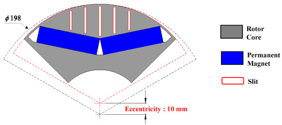
Therefore, the final model selected was the eccentricity model with the slit. An eccentricity of 10 mm was selected to minimize the induced EMF THD at the no-load and load drive. Figure 11 shows the final rotor shape design. In Table 4, the THD of the final design model was reduced by 41% at the load-drive compared to the conventional design with only eccentricity. It was also confirmed that the fundamental component of the induced EMF for the final design has higher values than that of the conventional design at the no-load and load drives.
Figure 11.
Cross-sectional view of the initial design.
Table 4.
Phase fundamental component and THD for the proposed models with an eccentricity of 10 mm.
3. Generator Characteristics and Analysis of Mechanical Stiffness
3.1. Generator Characteristics
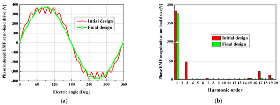
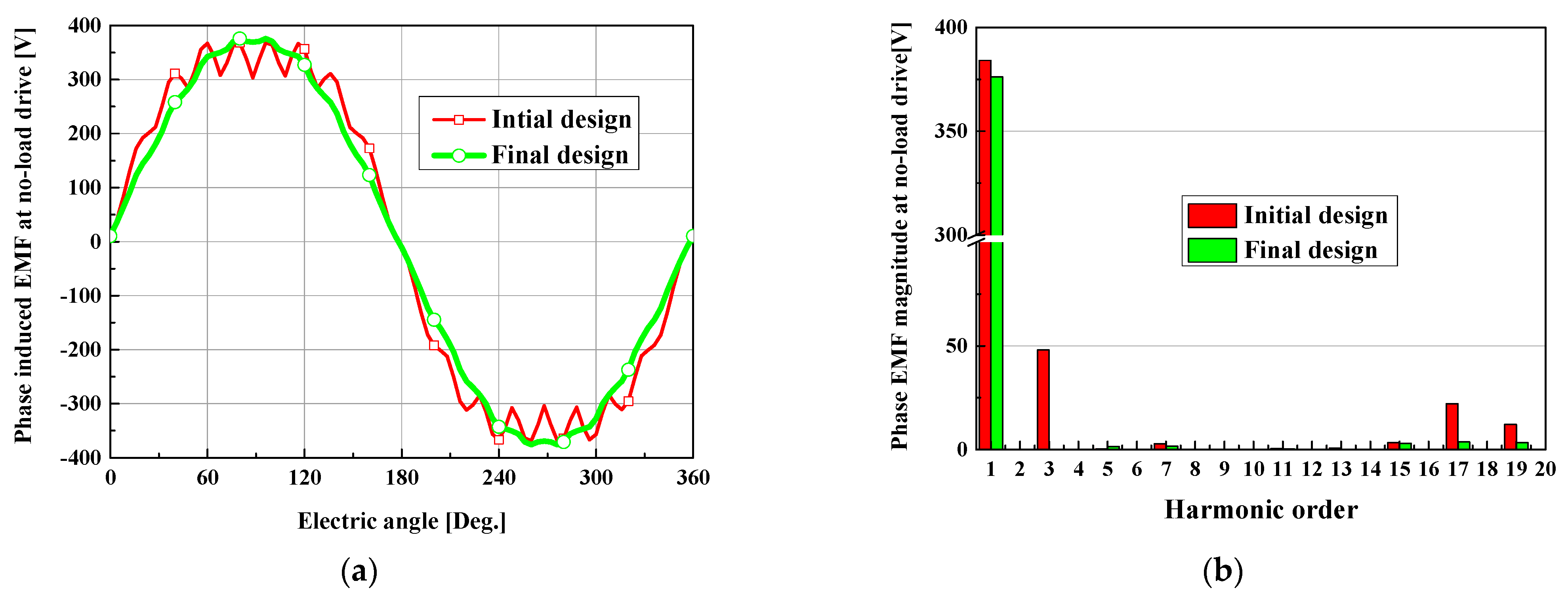
In order to investigate the characteristics of the PMSG for the final model, a comparison of the THD reduction between the initial and final rotor shape design is discussed. Figure 12 shows the wave form and harmonic order of the induced EMF at the no-load drives for the initial design of Figure 3 and the final design of Figure 11.
Figure 12.
Comparison of the induced EMF at no-load and load drives for the initial and final design: (a) wave form, and (b) harmonic order.
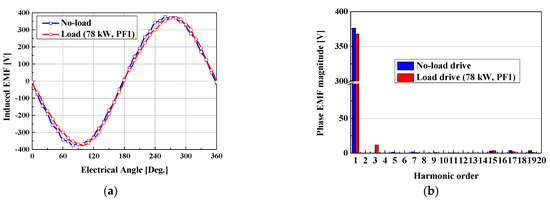
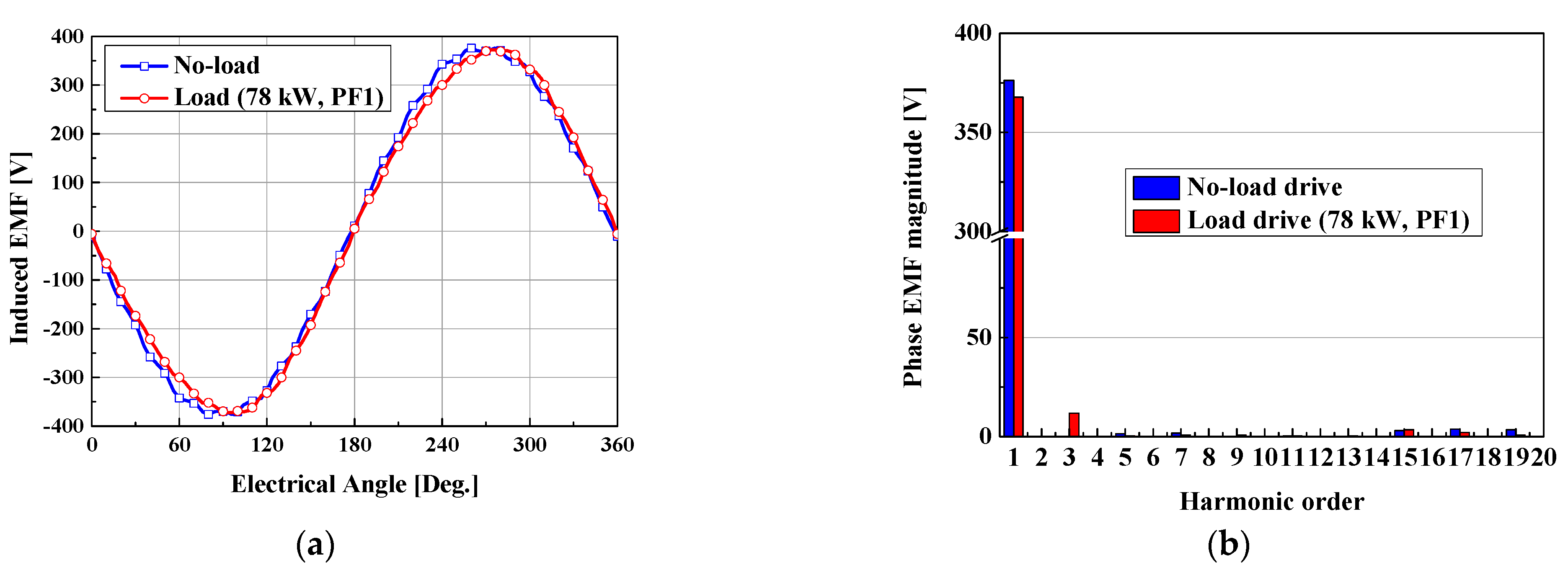
Figure 13 shows the wave form and harmonic order of the induced EMF at the no-load and load drives for the final design. In these figures, the 3rd harmonic order is significantly reduced. Therefore, it was confirmed that the 3rd harmonic order, due to the slot opening in the initial design, was significantly reduced.
Figure 13.
Induced EMF at no-load and load drives for the final design: (a) wave form, and (b) harmonic order.
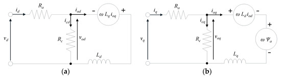
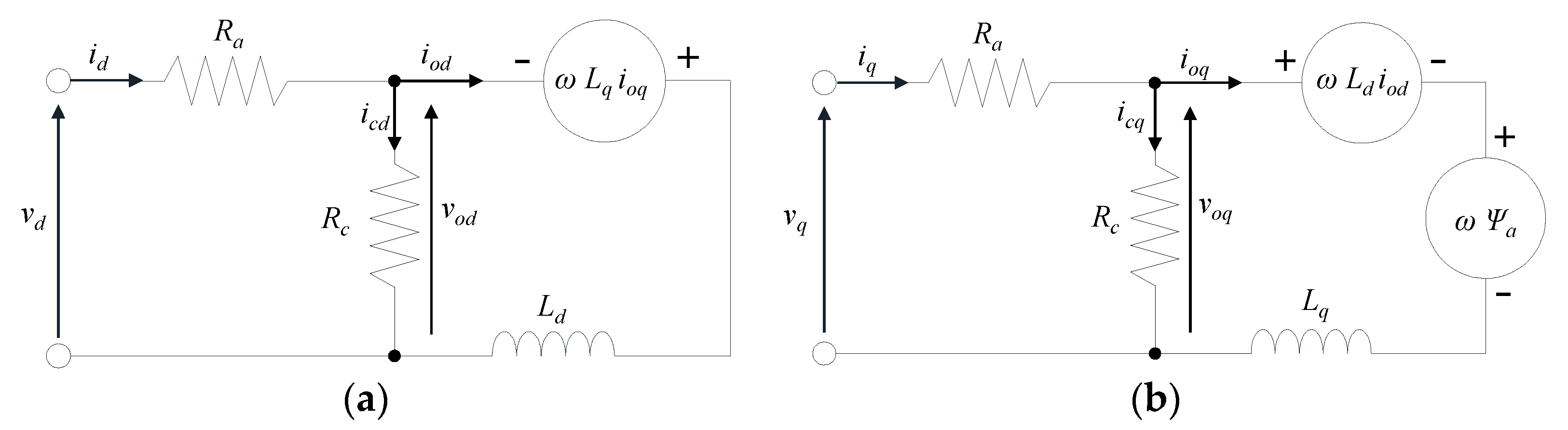
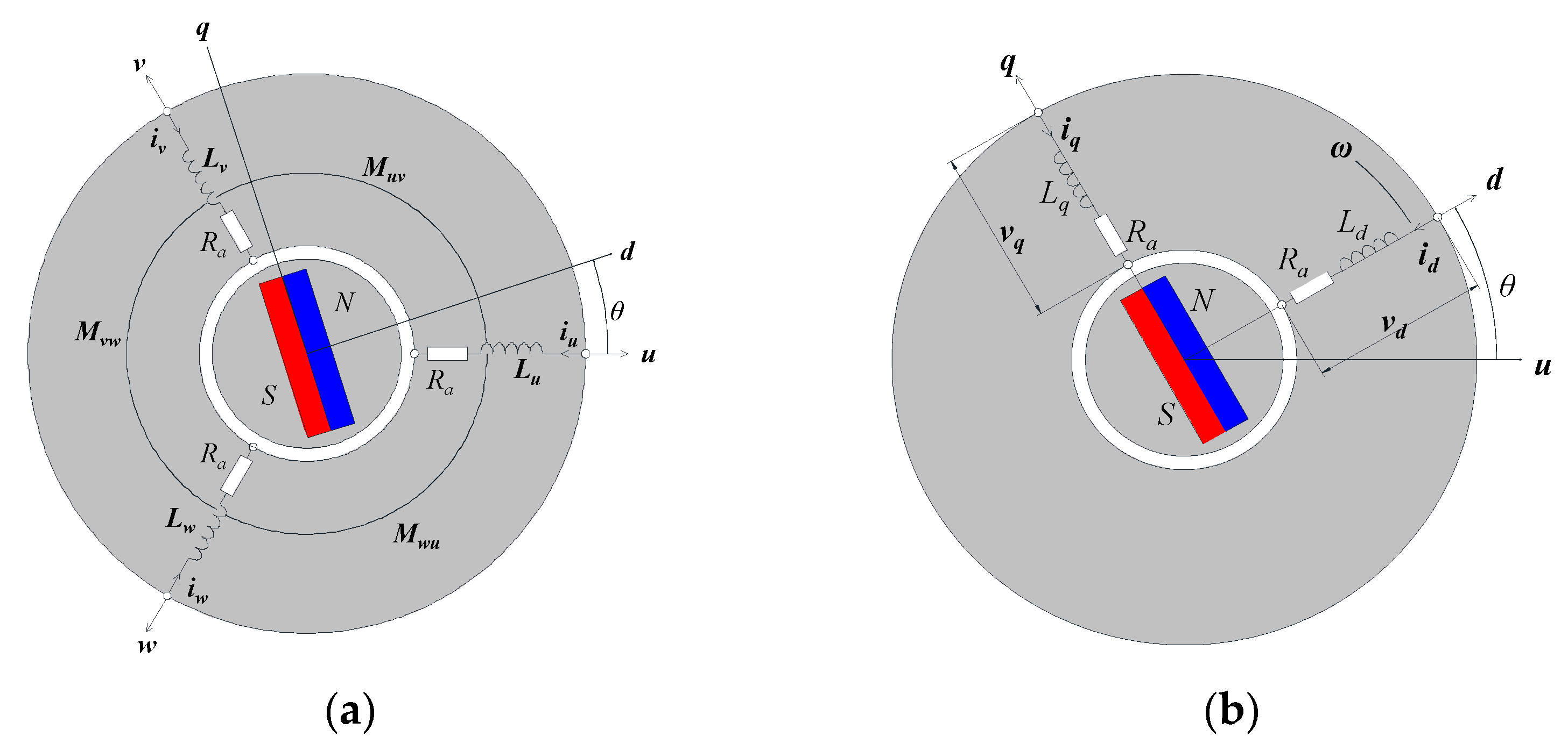
In order to verify the characteristics of the PMSG for the final design in Figure 11, the dq equivalent circuit was used as shown in Figure 14. The dq equivalent circuit has the strength of being able to analyze the characteristics of the PMSG with direct current (DC) circuits, as compared to an analysis of alternating currents for the 3-phase model [21].
Figure 14.
Equivalent circuit: (a) d axis, and (b) q axis.
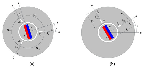
Figure 15a,b show the basic model of the 3-phase and dq transformed model, respectively. The voltage equation in Figure 15a is expressed by Equation (7) [22].
Figure 15.
Basic model of PMSG with two poles: (a) 3-phase model, and (b) transformed dq model.
In (7), the voltage equation has AC circuits with P, which is the differential operator. Equation (8) is the transformed matrix from the 3-phase model of Figure 15a to the dq model of Figure 15b [21].
The voltage equation of the dq model in Figure 14 is expressed by Equations (9) and (10). In (9) and (10), the parameters have constant values. Therefore, the characteristics of the PMSG can be analyzed with ease [22].
The nomenclatures of symbols in Figure 14 and Figure 15 and Equations (7)–(10) are described in the nomenclature.
The efficiency and voltage regulation, characteristics of the PMSG, were described using the dq equivalent circuit of Figure 14. The efficiency η was calculated in Equations (11)–(13). In (11) and (12), Pcu and Piron refer to copper loss and iron loss, respectively. In (13), T and ωm refer to mechanical torque and angular speed, respectively.
For the voltage regulation, %Reg was also calculated in (14) based on Figure 14. In (14), Vnoload and Vload refer to the induced EMF at the no-load and load drives, respectively.
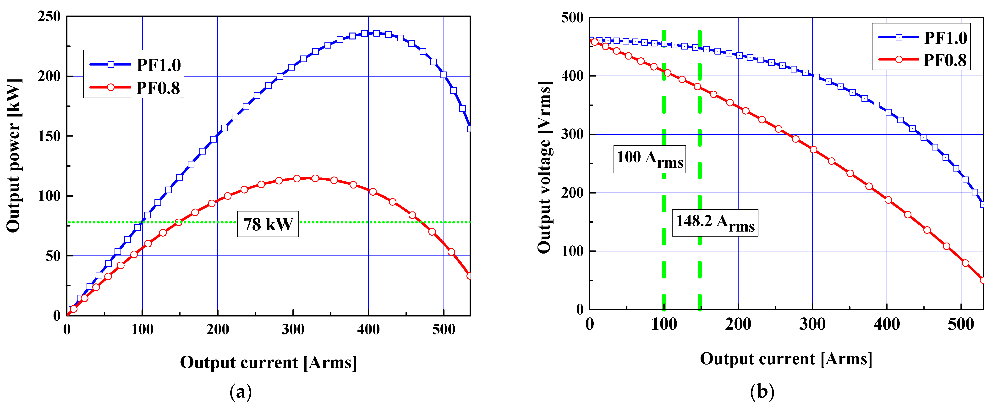
Figure 16a,b show the output power and voltage characteristics of the PMSG according to the input current. In Figure 16a, compared to the case of PF0.8, the PF1.0 was considerably reduced. In Figure 16b, compared to the case PF1.0, the voltage regulation of PF0.8 was significantly higher. In addition, the terminal voltage decreased sharply as the input current increased for the case of PF0.8.
Figure 16.
Output characteristics for the final design: (a) output power according to the output current, and (b) output voltage according to the output current.
Table 5 shows the analysis results for the case of PF1.0 and 0.8 under the same output power, 78 kW. For the PF0.8, the output current increased. The efficiency decreased and voltage regulation increased by the increased output current. However, the required efficiency is to satisfy the case of PF1.0 and 0.8, as shown in the design specification of Table 1.
Table 5.
Analysis results of load drive with 1800 rpm and 78 kW.
3.2. Analysis of Mechanical Stiffness
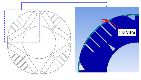
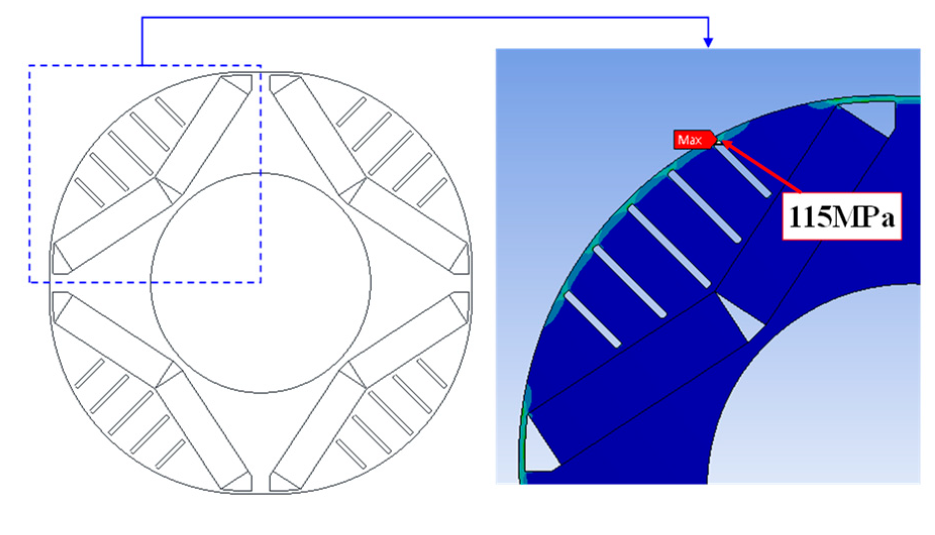
In this paper, since the slit shape was applied to the rotor core, the stress analysis was essential to secure the mechanical stiffness of the rotor [23]. Figure 17 shows the maximum stress result. A stress analysis was performed through a 2D structural finite element analysis.
Figure 17.
Maximum mechanical stress of the final rotor design.
The material properties of the rotor electric core were an iron core density of 7700 kg/m3 and a yield strength 270 N/mm2. The mechanical stiffness analysis was conducted under speed conditions of 1800 rpm. The maximum stress was 115 MPa in the location of the upper part of the slit. Therefore, it was confirmed that the mechanical stiffness is safe by verifying the safety factor 2.3.
4. Experiment
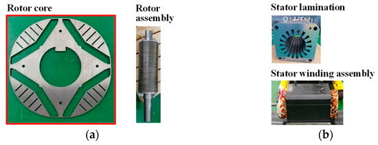
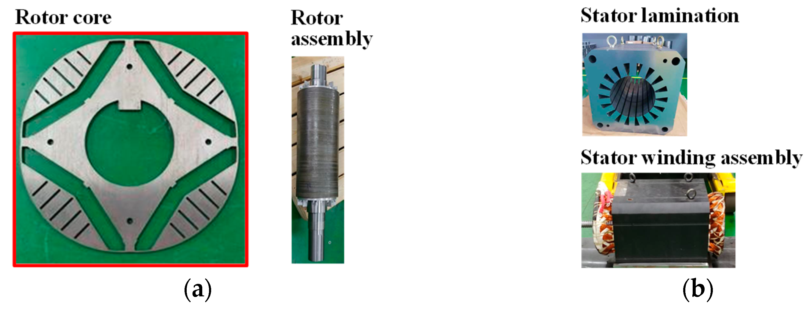
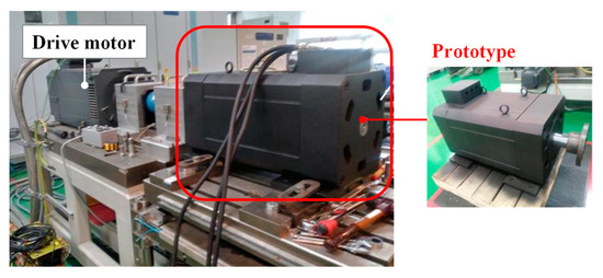
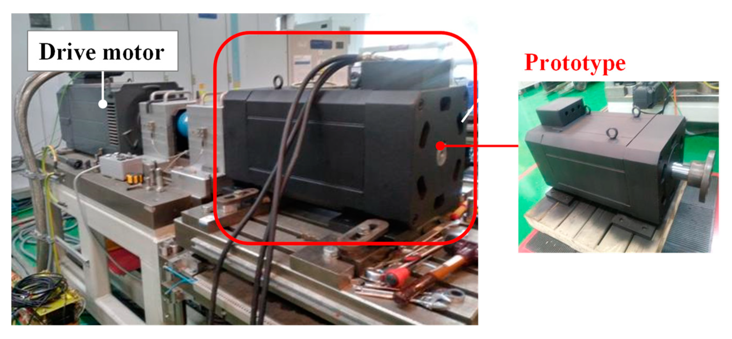
The measurement of the induced EMF at the no-load drive was conducted to verify the results of the 2D FEA for the final rotor shape design. Figure 18 shows the parts and prototype assembly. The final rotor shape design in Figure 11 is shown in Figure 18a. A 0.5 mm silicon steel sheet (50PN470) was used for the stator and rotor core. The prototype for the assembly of the rotor and stator in Figure 18 was mounted on the measurement equipment, as shown in Figure 19.
Figure 18.
Prototype of the final design: (a) rotor, and (b) stator.
Figure 19.
Measurement equipment.
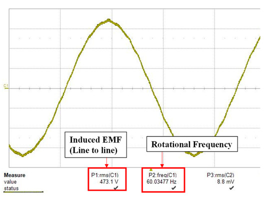
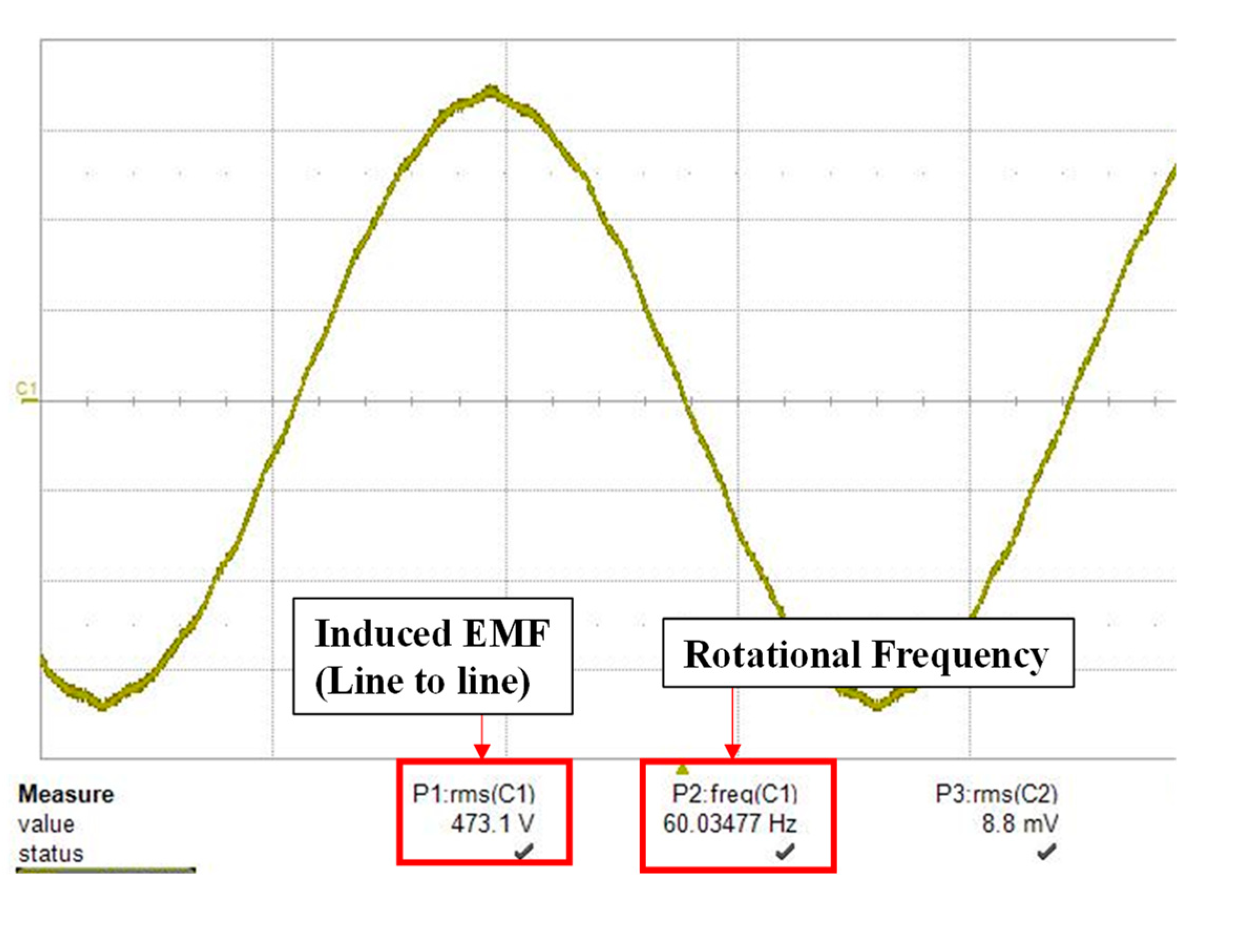
The stator assembly of the generator in Figure 18b was manufactured without housing. Since the housing was manufactured as a prototype, it was constructed in a rectangular shape, instead of a circular shape, to facilitate easy installation into the measurement equipment. The drive motor was connected to the prototype to measure the induced EMF at the no-load drive, as shown in Figure 19. The measurement conditions were a speed of 1800 rpm at room temperature (20 °C). In Figure 20, it was confirmed that the fundamental component value was measured at 495.7 Vrms (line-to-line voltage) and the rotational frequency was 60 Hz.
Figure 20.
Measured wave form of the induced EMF at no-load drive.
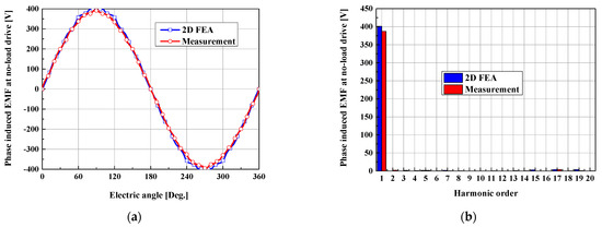
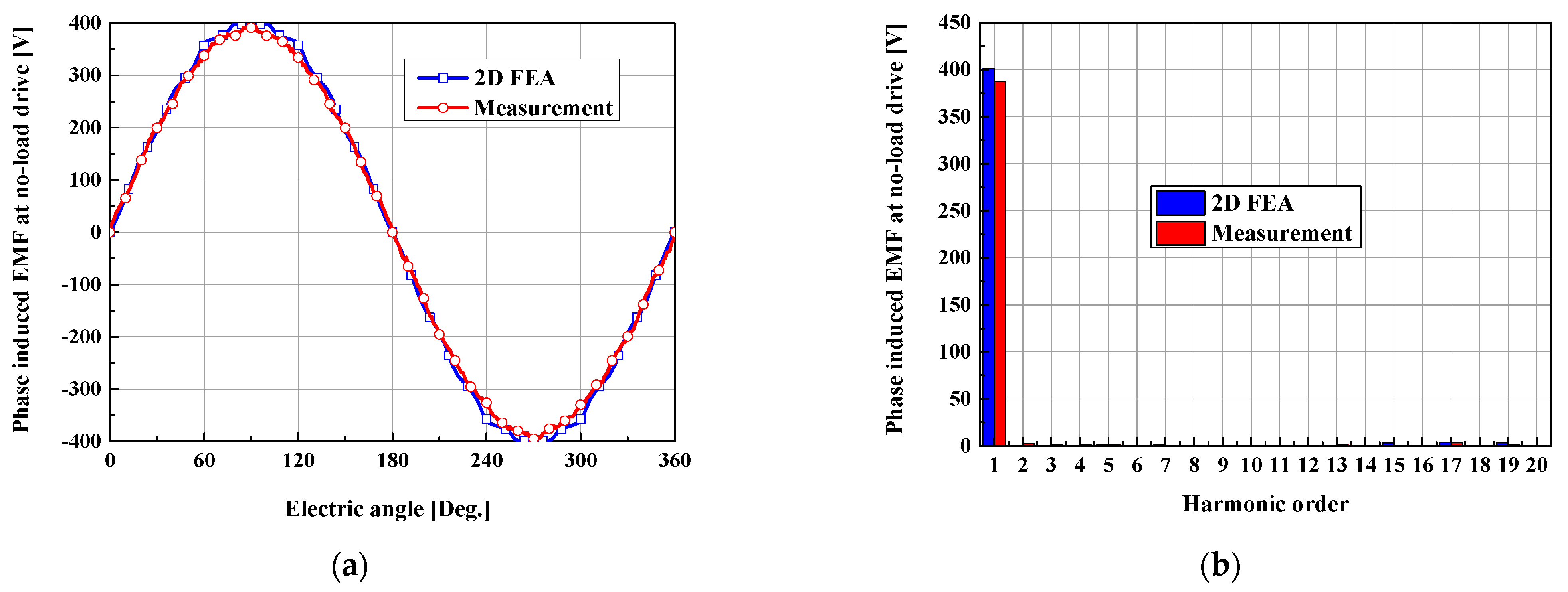
Figure 21 shows the results of the 2D FEA and measurement for the wave form of the induced EMF at the no-load drive. The Br = 1.3 [T] of the permanent magnet in Figure 18 was calculated to the final rotor model for the 2D FEA model considering the magnet’s temperature coefficient of α = −0.012 %/°C at 20 °C, the room temperature of the measurement equipment in Figure 19.
Figure 21.
Comparison of 2D FEA and measurement results: (a) wave form, and (b) harmonic order.
Table 6 lists the results of the 2D FEA and measurements for the fundamental component and the THD. In comparison with the 2D FEA results, the error percentages of the fundamental component and the THD for the measurement results were 3.5% and 6%, respectively. Compared to the 2D FEA results, the measurement results slightly decreased. It is expected that manufacturing disturbances, such as tolerance errors of magnet magnetization and shape dimension in rotor and stator, were the cause of this. However, the measurement results were close to the predicted results.
Table 6.
Phase fundamental component and THD at the no-load drive for the results of 2D FEA and measurement.
5. Conclusions
In this paper, the THD reduction design of the induced EMF was conducted to improve the power quality of a generator. In order to reduce the induced EMF THD, the eccentricity and slit shapes were proposed for the rotor shape design. The final design was determined at 10 mm of the eccentricity with the slit shape in the rotor.
The fundamental components of the induced EMF for the final design at the no-load and load drives were reduced by about 5% and 2%, respectively, when compared to the initial model. However, the induced EMF THD of the final design for the enhancement of generator power quality was significantly reduced to 88% and 70%, respectively, when compared to that of the initial design.
Based on the final design, with an eccentricity of 10 mm and a slit shape, the proposed design had better performance than the conventional design with the eccentricity in the rotor shape. Specifically, the THD of the design model was reduced by 41% at the load-drive compared to the conventional design with an eccentricity of 10mm as shown in the literature method [5,6,7,8,9,10,11,12]. It was also confirmed that the fundamental component of the induced EMF for the proposed design had a higher value than that of the conventional design at the no-load and load drives. Thus, the proposed design was able to reduce the weight of the PMSG due to the slit in the rotor shape. The reduced weight of the rotor assembly lead to an enhanced response for the initial design of the PMSG.
The prototype of the proposed design was manufactured to verify the characteristics of the PMSG. In comparison with the 2D FEA results, the error percentages of the fundamental component and THD for the measurement results were 3.5% and 6%, respectively. It was confirmed that the 2D FEA results were close to the measurement results.
Author Contributions
Conceptualization, C.-S.L.; methodology, C.-S.L.; software, C.-S.L.; validation., C.-S.L.; data curation, C.-S.L.; writing–original draft preparation, C.-S.L.; writing–review and editing, H.-J.K.; visualization, H.-J.K.; supervision, H.-J.K. All authors have read and agreed to the published version of the manuscript.
Funding
This research received no external funding.
Institutional Review Board Statement
Not applicable.
Informed Consent Statement
Not applicable.
Data Availability Statement
Not applicable.
Conflicts of Interest
The authors declare no conflict of interest.
Nomenclature
| ψa | Magnetic flux linkage on dq axis |
| Ld, Lq | Inductances on dq axis |
| Ra | Phase resistance |
| Rc | Core loss resistance on dq axis |
| icd, icq | Currents for core loss resistance Rc for dq axis |
| id, iq | Currents on dq axis |
| vod, voq | Voltages for core loss resistance Rc for dq axis |
| vd, vq | Voltages on dq axis |
| ω | Electric angular velocity |
| ωm | Mechanical angular velocity |
| θ | Rotor position |
| Lu, Lv, Lw | Self-inductances of each phase for 3-phase model |
| Muv, Mvw, Mwu | Mutual inductances of each phase for 3-phase model |
| iu, iv, iw | Currents of each phase for 3-phase model |
| vu, vv, vw | Voltages of each phase for 3-phase model |
| ψf | Magnetic flux linkage for 3-phase model |
| p | Differential operator |
References
- Kim, K.H.; Paul, S.; Bang, D.J.; Chang, J.H. Performance of permanent magnet synchronous generator for urban water pipleline energy harvester considering slotting and load effect on radial force characteristic. IEEE Trans. Magn. 2021, 57, 8203105. [Google Scholar] [CrossRef] [Scilit]
- Al-Adsani, A.; Beik, O. Design of a multiphase hybrid permanent magnet generator for series hybrid EV. IEEE Trans. Energy Convers. 2018, 33, 1499–1507. [Google Scholar] [CrossRef] [Scilit]
- Zhu, Z.Q.; Xia, Z.P.; Wu, L.J.; Jewell, G.W. Influence of slot and pole number combination on radial force and vibration modes in fractional slot PM brushless machines having single and double layer windings. In Proceedings of the IEEE Energy Conversion Congress and Exposition (ICEM), San Jose, CA, USA, 20–24 September 2009. [Google Scholar]
- Fang, L.; Hong, J.P. Flux-barrier design technique for improving torque performance of interior permanent magnet synchronous motor for driving compressor in HEV. In Proceedings of the IEEE Vehicle Power and Propulsion Conference, Dearborn, MI, USA, 7–10 September 2009. [Google Scholar]
- Hwang, K.Y.; Kwon, B.I. Rotor pole design in spoke-type brushless DC motor by response surface method. IEEE Trans. Magn. 2007, 43, 1833–1836. [Google Scholar] [CrossRef] [Scilit]
- Ruangsinchaiwanich, S.; Zhu, Z.Q.; Howe, D. Influence of magnet shape on cogging torque and back-emf waveform in permanent magnet machines. In Proceedings of the IEEE Energy Conversion Congress and Exposition (ICEM), Nanjing, China, 27–29 September 2005. [Google Scholar]
- Lee, C.S.; Cha, K.S.; Park, J.C.; Lim, M.S. Tolerance-insensitive design of the magnet shape for a surface permanent magnet synchronous motor. Energies 2020, 13, 1311. [Google Scholar] [CrossRef] [Scilit]
- Yu, J.S.; Lee, S.H. Stator and rotor shape optimum design of brushless permanent magnet motor for automotive cooling device. In Proceedings of the IEEE Vehicle Power and Propulsion Conference, Seoul, Korea, 9–12 October 2012. [Google Scholar]
- Park, Y.U.; Kim, D.K. A rotor shape design of interior PM motor for reducing cogging torque in electric air-conditioning system of HEV. In Proceedings of the International Conference Electrical Machines and Systems (ICEM), Busan, Korea, 26–29 October 2013. [Google Scholar]
- Ding, Z.; Zhang, B.; Yin, D. A design of fractional-slot concentrated winding IPM synchronous motor electric vehicle. In Proceedings of the 43rd Annual Conference of the IEEE Industrial Electronics Society, Beijing, China, 29 October–1 November 2017. [Google Scholar]
- Yu, Y.; Liang, Z. The influence of optimizing rotor on the performance and the iron loss of the permanent machine. In Proceedings of the International Conference Electrical Machines and Systems (ICEM), Hangzhou, China, 22–25 October 2014. [Google Scholar]
- Xu, H.; Li, J. A sleeve-free interior permanent magnet high speed motor with non-uniform airgap. In Proceedings of the IEEE International Electric & Drive Conference (IEMDC), San Diego, CA, USA, 12–15 May 2019. [Google Scholar]
- Kim, H.J.; Jeong, J.S.; Yoon, M.H.; Moon, J.W.; Hong, J.P. Simple size determination of permanent magnet synchronous machines. IEEE Trans. Ind. Electron. 2017, 64, 7972–7983. [Google Scholar] [CrossRef] [Scilit]
- Miller, T.J.E. Brushless Permanent-Magnet and Reluctance Motor Drives; Oxford Science Publications: New York, NY, USA, 1989; pp. 20–24. [Google Scholar]
- Hiramastu, D.; Tsujikwa, K.; Ueda, T.; Fujita, M. Winding method to reduce vibration and loss caused by fractional slot of synchronous machine. Electr. Eng. Jpn. 2017, 198, 1130–1137. [Google Scholar]
- Zhu, Z.Q.; Howe, D.; Bolte, E.; Ackermann, B. Instantaneous magnetic field distribution in brushless permanent magnet dc motors, part I: Open-circuit field. IEEE Trans. Magn. 1993, 29, 124–135. [Google Scholar] [CrossRef] [Scilit]
- Lubin, T.; Mezani, S.; Rezzoug, A. 2D exact analytical model for surface-mounted permanent-magnet motors with semi-closed slots. IEEE Trans. Magn. 2010, 47, 479–492. [Google Scholar] [CrossRef] [Scilit]
- Li, Y.; Chai, F.; Song, Z.; Li, Z. Analysis of vibrations in interior permanent magnet synchronous motors considering air-gap deformation. Energies 2017, 17, 1259. [Google Scholar] [CrossRef] [Scilit]
- Gieras, J.F.; Wang, C.; Lai, J.C. Noise of Poly Phase Electric Motors; CRC Press: Boca Raton, FL, USA, 2006; pp. 49–53. [Google Scholar]
- Jung, Y.H.; Park, M.R.; Lim, M.S. Asymmetric rotor design of IPMSM for vibration reduction under certain load condition. IEEE Trans. Energy Convers. 2020, 35, 928–937. [Google Scholar] [CrossRef] [Scilit]
- Qiao, W.; Qu, L.; Harley, R.G. Control of IPM synchronous generator for maximum wind power generation considering magnetic saturation. IEEE Trans. Ind. Appl. 2009, 45, 1095–1105. [Google Scholar] [CrossRef] [Scilit]
- Levron, Y.; Belkov, J.; Baimel, D. A tutorial on dynamics and control of power systems with distributed and renewable energy sources based on the DQ0 transformation. Appl. Sci. 2018, 8, 1661. [Google Scholar] [CrossRef] [Scilit]
- Jung, J.W.; Kim, D.J.; Hong, J.P. Mechanical stress reduction of rotor core of interior permanent magnet synchronous motor. IEEE Trans. Magn. 2014, 50, 911–914. [Google Scholar]


Publisher’s Note: MDPI stays neutral with regard to jurisdictional claims in published maps and institutional affiliations. |
© 2021 by the authors. Licensee MDPI, Basel, Switzerland. This article is an open access article distributed under the terms and conditions of the Creative Commons Attribution (CC BY) license (https://creativecommons.org/licenses/by/4.0/).