


Abstract
Active vibration control is crucial for mitigating harmful resonant vibrations in structures subjected to harmonic loads. While antiresonant (zero-placement) methods are effective for this purpose, existing state-feedback solutions require full state measurement, and output-feedback approaches often prioritize resonance assignment over direct harmonic cancellation. This work bridges this gap by proposing a novel systematic design for a proportional–derivative (PD) output-feedback controller to achieve antiresonance for second-order linear systems with a time delay in the actuators. The method first computes a homogeneous gain solution. It then leverages the parametrization of all antiresonant solutions as a constraint within a genetic algorithm optimization. The algorithm optimizes both the stability margin, characterized by an -disk criterion, and the number of encirclements of the critical point in the complex plane, as assessed by the Generalized Nyquist Stability Criterion. The proposed approach provides a practical, optimized output-feedback strategy for precise rejection of harmonic disturbances, as demonstrated through a collection of numerical examples from real-world applications. The results confirm the method’s effectiveness in synthesizing stabilizing controllers that enforce antiresonance while ensuring robust stability margins.
1. Introduction
1.1. Motivation
The mechanical vibration of structural systems is a ubiquitous phenomenon across various contexts and real-world applications. In industrial processes, piping, chimneys, and compressor and pump bases, for example, are among the structures that can experience harmful vibrations due to harmonic loads and perturbations [1,2,3,4,5,6]. Possible causes include gust winds, earthquakes, misalignment, and flux pulsation; they can induce resonance with the structure’s natural frequencies. To mitigate the effects of harmonic loads, passive [7,8], semi-active [9,10], and active techniques [11] can be used. Passive or semi-active techniques have some disadvantages, such as being generally ad hoc and addressing only localized vibrations; however, they are inexpensive. Active vibration control methods based on linear dynamic models are more costly to implement but are flexible and can mitigate vibrations across the structure. Active vibration control methods include resonant and antiresonant approaches. In the resonant case, a prescribed location—strict or regional—for the system eigenstructure is determined by the designer, and feedback controllers, such as state feedback [12,13,14] or output feedback (static or dynamic) [15,16], are computed to achieve the specified spectrum or eigenstructure. Antiresonant methods are designed to address so-called harmonic loads or perturbations. In that case, a harmonic excitation enters the system in a given degree of freedom, and the goal is to cancel its effect in steady-state on another target degree of freedom of relevance. To achieve this, zeros are placed at the chosen impedance. Since the seminal work of [17], a series of prominent contributions for antiresonance or zero placement using system frequency response—also known as receptance—have been made to the state of the art, as summarized in the next subsection.
1.2. State of the Art
Active vibration control, encompassing both collocated and non-collocated configurations, has been extensively developed over recent decades through various methodological, theoretical, and technological advancements. A key challenge in practical implementation is the presence of time delays in the control loop, which can degrade performance and even destabilize the system. Methodologically, advanced pole-zero placement techniques have been proposed to address these issues. For instance, Mottershead et al. [18] introduced a receptance-based method for output feedback that assigns poles and zeros without requiring system matrices, effectively handling delays and enabling collocated control. Similarly, Singh [19] generalized partial pole assignment for aeroelastic systems with a time delay, demonstrating that targeted flutter modes can be stabilized without affecting other modes. Technological implementations also focus on compensating for delays and periodic disturbances. Yuksel et al. [20] developed an internal model control scheme for systems with a long dead time, using a filter–delay pair to reject harmonic disturbances, validated experimentally on a mechatronic setup. Hirschfeldt et al. [21] proposed a second-order compensator for non-collocated velocity feedback control, where compensator parameters are derived from measured antiresonances, circumventing the need for a plant model. These works collectively illustrate the evolution of robust, implementable control strategies that explicitly account for time delay and system uncertainties. Direct harmonic perturbation decoupling in second-order systems was initially characterized by Mottershead et al. [7,17], who proposed zero-placement conditions and a formulation for single-input systems based on system receptance. Subsequently, several contributions were made, including the extension to multi-input systems and the concept of an adjunct system [22]. For systems with a delay, a recent work [23] synergizes the results with the Nyquist stability criterion explored in [14,24,25], incorporating time delays in the measurements. In that work, state-feedback controllers are designed, which demand full state measurement—displacements and velocities. Output feedback for an antiresonant optimized design was proposed in [26] using displacement and velocity measurements. The use of output-feedback PD controllers for active vibration control in systems with actuation delays to cancel harmonic perturbations is, to the best of our knowledge, a novel solution.
1.3. Contribution of This Work and Paper Organization
In this paper, antiresonant/zero placement is proposed by computing a proportional–derivative (PD) output-feedback controller that ensures closed-loop stability based on the Generalized Nyquist Stability Criterion [27]. The proposed approach can achieve antiresonant control with guaranteed gain and phase margins, considering multiple harmonic disturbances frequencies, collocated or non-collocated sensor–actuators, and (possibly) different delays in each of the actuators (inputs). To this end, a homogeneous solution for the proportional and derivative feedback gains that stabilize the system is computed. Then, the parametrization of all antiresonant solutions is used as a constraint in a genetic algorithm search for an optimal solution that minimizes the stability margins represented by an -disk and the number of encirclements of the critical point in the complex plane [28,29]. The rest of the paper is organized as follows: (i) Section 2 presents the preliminary concepts and states the problem to be solved; (ii) Section 3 describes the proposed approach to output-feedback PD controller design in a systematic way; (iii) Section 4 presents numerical examples borrowed from real-world applications to illustrate the proposal; (iv) Section 5 outlines a brief discussion of the results and the advantages and drawbacks of the proposal; (v) Section 6 presents some conclusions and perspectives.
2. Preliminaries and Statement of the Problem
Let the second-order linear n-DOF system be defined as
in which are, respectively, the mass, damping, and stiffness matrices; is the influence matrix for the control input ; are standard vectors of dimension n; is a harmonic disturbance; is the sensing (measurement) matrix that defines the measurement output vector ; and is the p-th DOF of the system.
For the statement of the problem, the approach will be considered using a proportional–derivative (PD) output-feedback solution of the form
with . If the input vector is subject to fixed time delays of (possibly) different values, then by taking the Laplace Transform with relaxed initial conditions, one can write in the frequency domain in the following relation:
in which the delay diagonal matrix is given as
The antiresonant control for this closed-loop dynamics can then be stated as
Problem 1.
In summary, the influence of the harmonic disturbance entering the system through the p-th DOF on the displacement of the q-th DOF is perfectly canceled at steady-state with the computed PD output-feedback controller.
3. The Proposed Approach
3.1. Zero Assignment
By developing (5), one can find the frequency domain generalized displacement
from which left-multiplying by gives
The matrix is the well-known closed-loop receptance. Notice that for annihilation of at steady-state, as required in Problem 1 the undamped complex zero pair must be made of zeros of the cross-receptance . Let be the closed-loop dynamic stiffness matrix of the controlled system, that is,
Thus, the receptance can then be written as
in which is the adjoint matrix of the dynamic stiffness. As can be found in [30], this matrix has, by construction, the entries given by
In the above equation, is the minor, computed after the deletion of the q-th row and p-th column of the dynamic stiffness matrix. Notice that the zeros of are the roots of the equation:
Denoting the bases for the right null spaces of the standard vectors and , respectively, as the matrices and , it can be verified that
with
The dynamic stiffness matrix and its respective matrices above are called the adjunct system of (1). The poles of the associated receptance are the zeros of . In summary, to proceed with the zero assignment that is a solution for Problem 1, the pole assignment of must be performed.
Focusing now on for pole assignment, one has
The Sherman–Morrison–Woodbury formula can be applied to expand this inverse, resulting in
with . The characteristic equation for (17) is given as
In order to assign a set of roots to this equation, say, in closed-loop, since is a closed-loop pole of the system, then
This is equivalent to stating that the rank of the matrix
is equal to . If one picks a vector from the null space of , say, , then the following result holds:
Expanding this, one obtains
Applying the ’vec-trick’ to the above equation and casting for results in
Such a system can be written in a compact form as , with an obvious definition of the system matrices. This is a linear system with equations, dictated by the number of zeros to be assigned and the dimension of the measurement vector, and unknowns, the elements of the feedback gain matrices. Some facts regarding the system solutions are as follows:
- (i)
- The system has solutions if for all nontrivial vectors , , that is, is full row rank;
- (ii)
- If this condition is matched, the number of free variables in the solution is ;
- (iii)
- The solutions have the form [22,23]:where is a particular solution; is the basis of the null space of ; and is the free parameter of the solution.
Notice that any solution computed using (20) can be used as the homogeneous in (21). As an instance, the Moore–Penrose inverse can be applied to compute
Other generalized inverses can be used to compute .
Remark 1.
Regarding fact (i), this rank conditions holds only if the number of outputs is less than or equal to the number of inputs—, because, from (19),
That is, the rank condition described can no longer be assured. Fortunately, since the adjunct system’s receptance has other alternative forms, in particular
characteristic Equation (18) can be written in the dual form
The same steps for the development of the case in which can be reproduced, by interplay:
and thus one obtains a linear system like (20) that is not rank-defective.
3.2. Optimization-Based Solution
The parametrization of all antiresonant feedback matrices (21) gives the designer the possibility of using the free parameter for search in a generally large space of dimension [22,31]. An indispensable requirement is that the solution must yield a stable closed-loop system. Several works using state or state-derivative feedback controllers [23,24,25] addressed this issue using the Nyquist stability criterion [32], or its generalized version for the multi-input case [27]. The closed-loop receptance can be deduced as
The closed-loop poles of (25) are the roots of the characteristic equation
where is the so-called loop gain function of the controlled system. Lemma 1 in Appendix A.1 establishes the conditions for the closed-loop system to be stable according to the Generalized Nyquist Criterion. Thus, given a prescribed value of that imposes a delay and gain margins for the closed-loop system, and by considering a frequency range sufficiently large and far from the highest natural frequency of the open-loop poles, , the following optimization problem can be solved to compute the feedback gain matrices and :
Remark 2.
The -disk establishes an exclusion zone for the Nyquist plot; that is, the eigenloci must be enforced to remain outside those limits. As a result, lower bounds for gain and phase (delay) margins are guaranteed. These margins imply robustness against uncertainties in the system model. Even parametric uncertainties that simultaneously affect the gain and the phase plus their respective crossover frequencies can be absorbed by these guaranteed margins, provided that in the worst case scenario, the constraints for stability are not violated. Some relevant contributions on this topic can be found in [33].
Remark 3.
In a similar manner as in Remark 1, the loop function matrix produces fixed null eigenvalues when . Thus, the alternative loop function
can be used for a more efficient eigenloci construction.
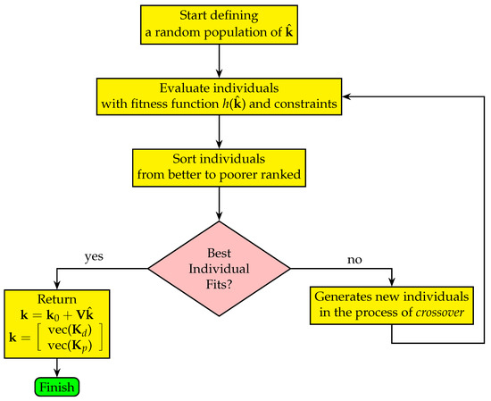
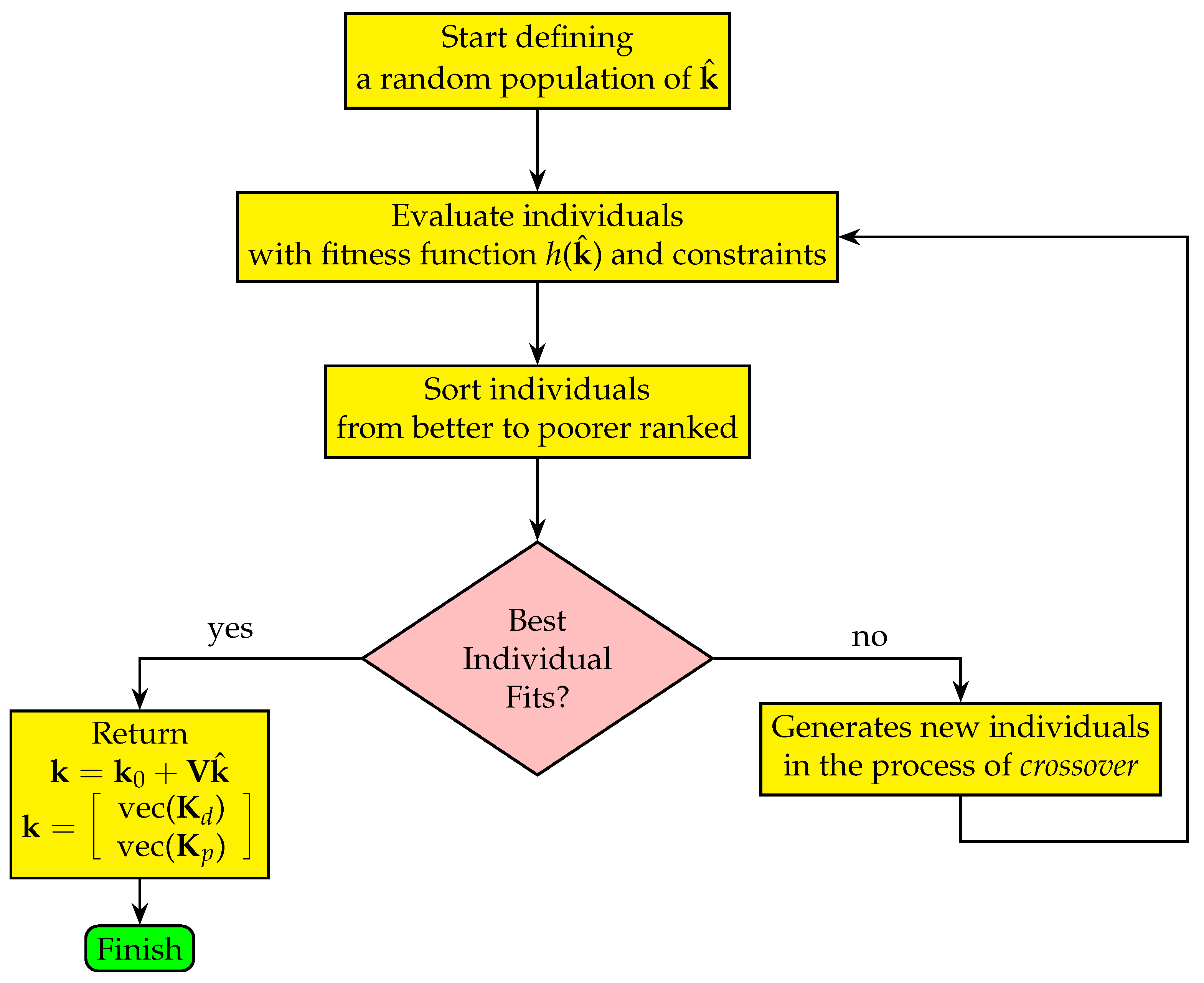
The solution to optimization problem (27) is not trivial. Although various heuristic methods exist in the literature, a Genetic Algorithm (GA) was chosen for this task. This choice is motivated by a GA’s ability to explore large solution spaces, adapt to dynamic conditions, and optimize complex functions. Furthermore, its robustness in handling multi-modal problems and its capability to find near-optimal solutions made it particularly suitable for this study. A general flowchart to the solution computation with a GA is displayed in Figure 1. The classical steps of a general GA can be used to build the script. In the crossover stage, one can choose from among the available recombination methods, such as single-point, two-point, intermediate, scattered, arithmetic, or any heuristic approach.
Figure 1.
General flowchart to solve the optimization problem (27) with a GA.
4. Numerical Studies
4.1. Test Case Descriptions
Three examples demonstrate the effectiveness of PD controllers for antiresonance performance when the proposed approach is applied. In the first one, a spring-mass-damper with four DOFs, two control inputs, and two measured displacements in a collocated sensor–actuator scheme is studied. Such an example can model several kinds of structural systems. In the second example, an unstable open-loop model for the friction-induced vibration phenomenon in a belt conveyor with a structural contact point is employed to illustrate the proposed antiresonant design. The third example is a reduced-order model of a building with active vibration control applied to two target harmonic disturbance frequencies.
4.1.1. Case I: Collocated Sensors and Actuators in a Structural System
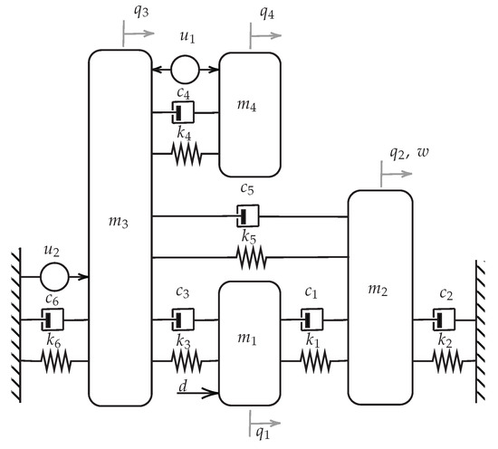
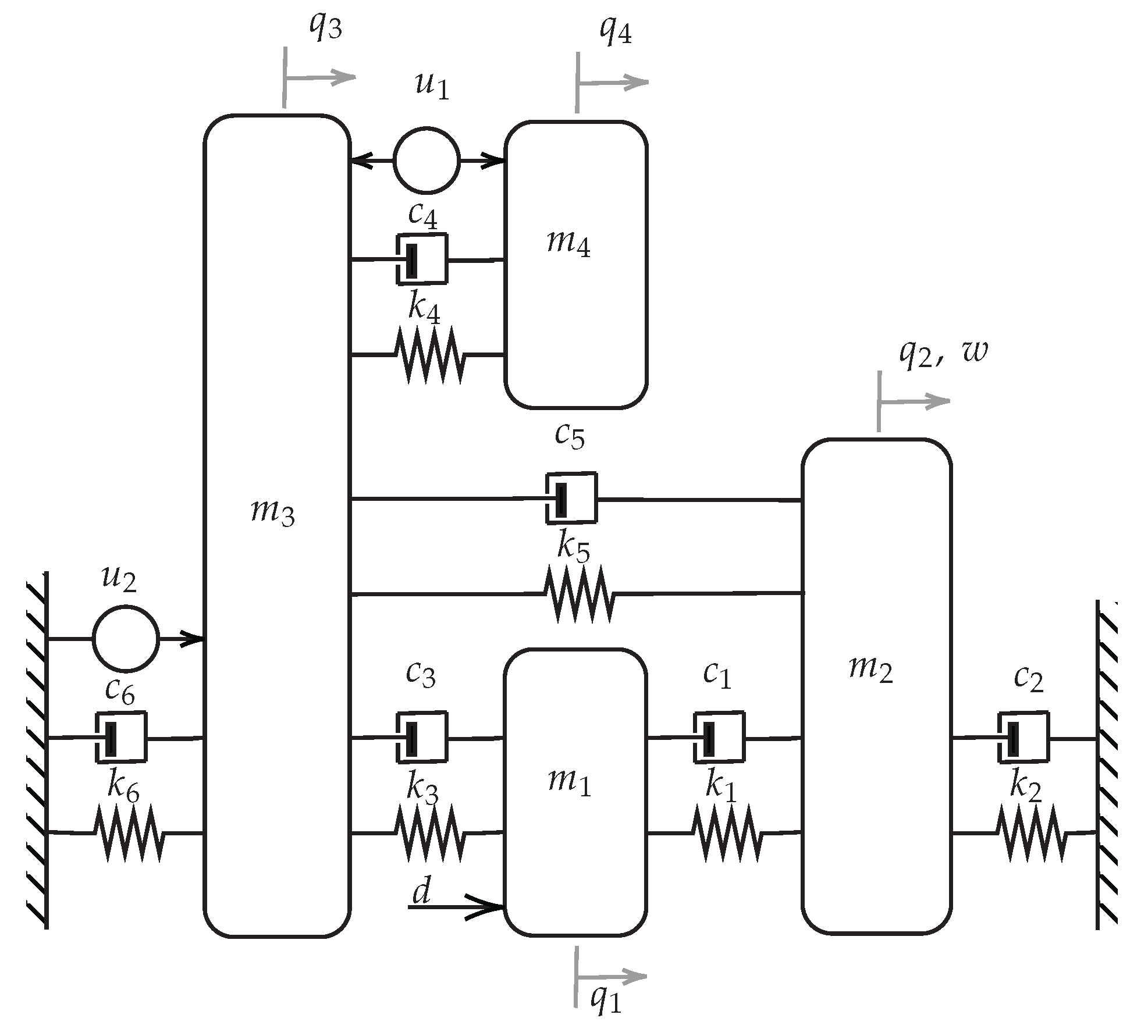
This example illustrates the antiresonant design of a four-DOF mass-spring-damper, as shown in Figure 2. The harmonic perturbation , with , enters in the 1st DOF and must be suppressed in the 2nd DOF; that is:
Figure 2.
Mechanical system with 4 DOFs of test case in Section 4.1.1.
The system mass, damping, and stiffness matrices together with the influence matrix were borrowed from the experimental assembly in [26] and, considering collocated measurement, are given as
The delays at the input are considered as s. An -disk with radius , that is, , is chosen for the design. The system is open-loop stable, that is, ; then, the encirclements of the critical point must be null. A stabilizing homogeneous solution is computed using the parameters
The feedback matrices are computed, resulting in
The Nyquist contour with the fixed disk is depicted in Figure 3, and the system stability can be certified using this visualization: no encirclements are observed in the plot. The time-domain responses of the target DOF for harmonic disturbance rejection and the demanded control effort are displayed respectively in Figure 4 and Figure 5.
Figure 3.
Generalized Nyquist contour for the closed-loop system of the test case in Section 4.1.1. The red line is the -disk circumference, and the black cross is the critical point .
Figure 4.
Time-domain response of the target DOF before and after loop closing.
Figure 5.
Control effort of test case in Section 4.1.1.
4.1.2. Case II: Non-Collocated Sensor and Actuator Control of System with Friction-Induced Vibration
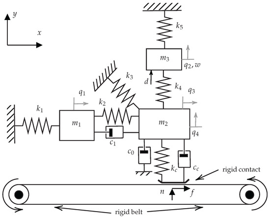
In this test case, the well-known friction-induced vibration phenomenon [34] is revisited, in an example borrowed from [35]. The mechanical system is displayed in Figure 6. The belt movement creates friction at the contact point, and depending on the friction coefficient, unstable vibration can occur. For design purposes, the system matrices for this system are the following:
Figure 6.
Friction-induced vibration system.
Input delays are given as s, s, and s. The system has an unstable pair of eigenvalues, namely, ; that is, . A harmonic perturbation , with , enters the system in the second DOF, and the effect at itself, that is, the point of inertance , must have an annihilator zero pair . Thus, one has
As in the previous test case, is adopted. A stabilizing homogeneous solution is computed using the parameters
The feedback gain matrices are then computed, resulting in
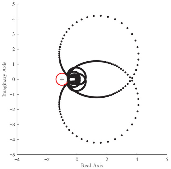
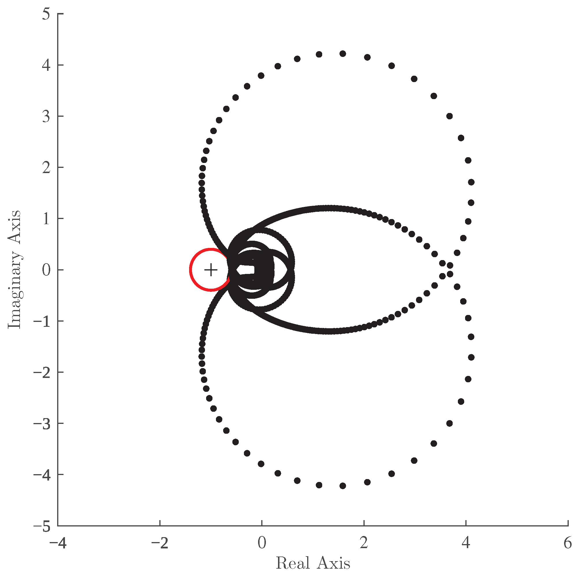
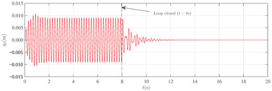
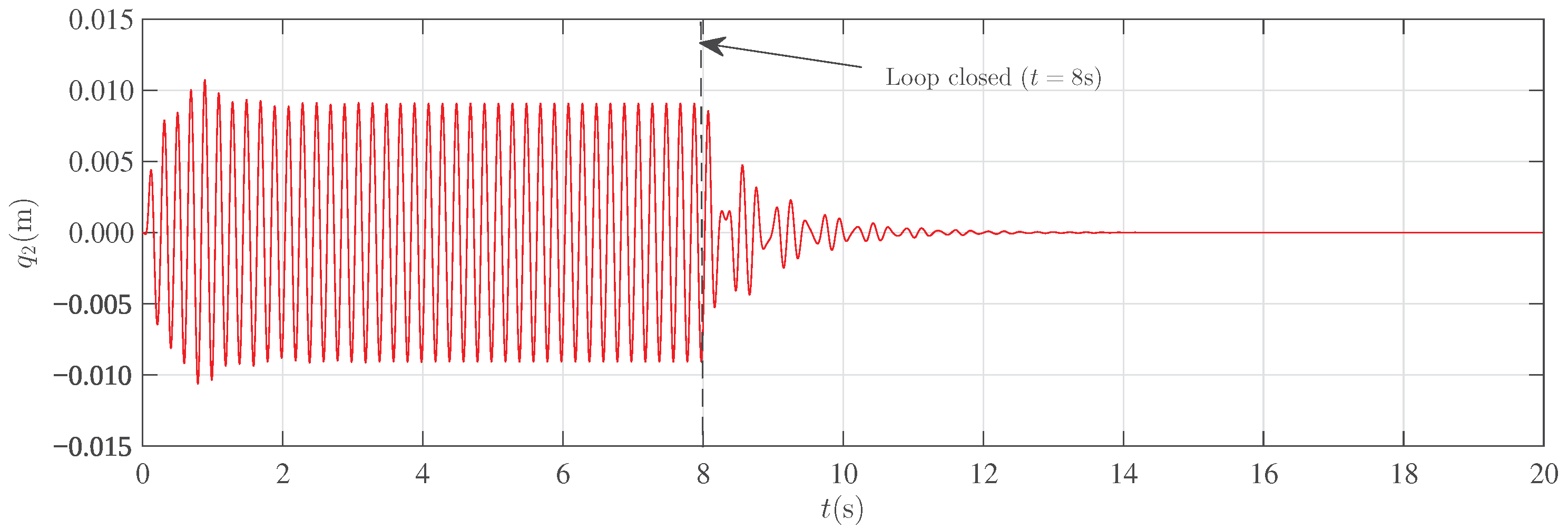
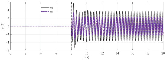
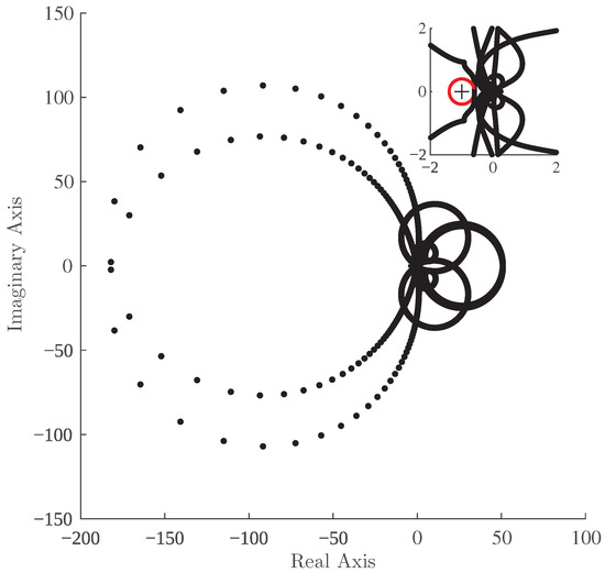
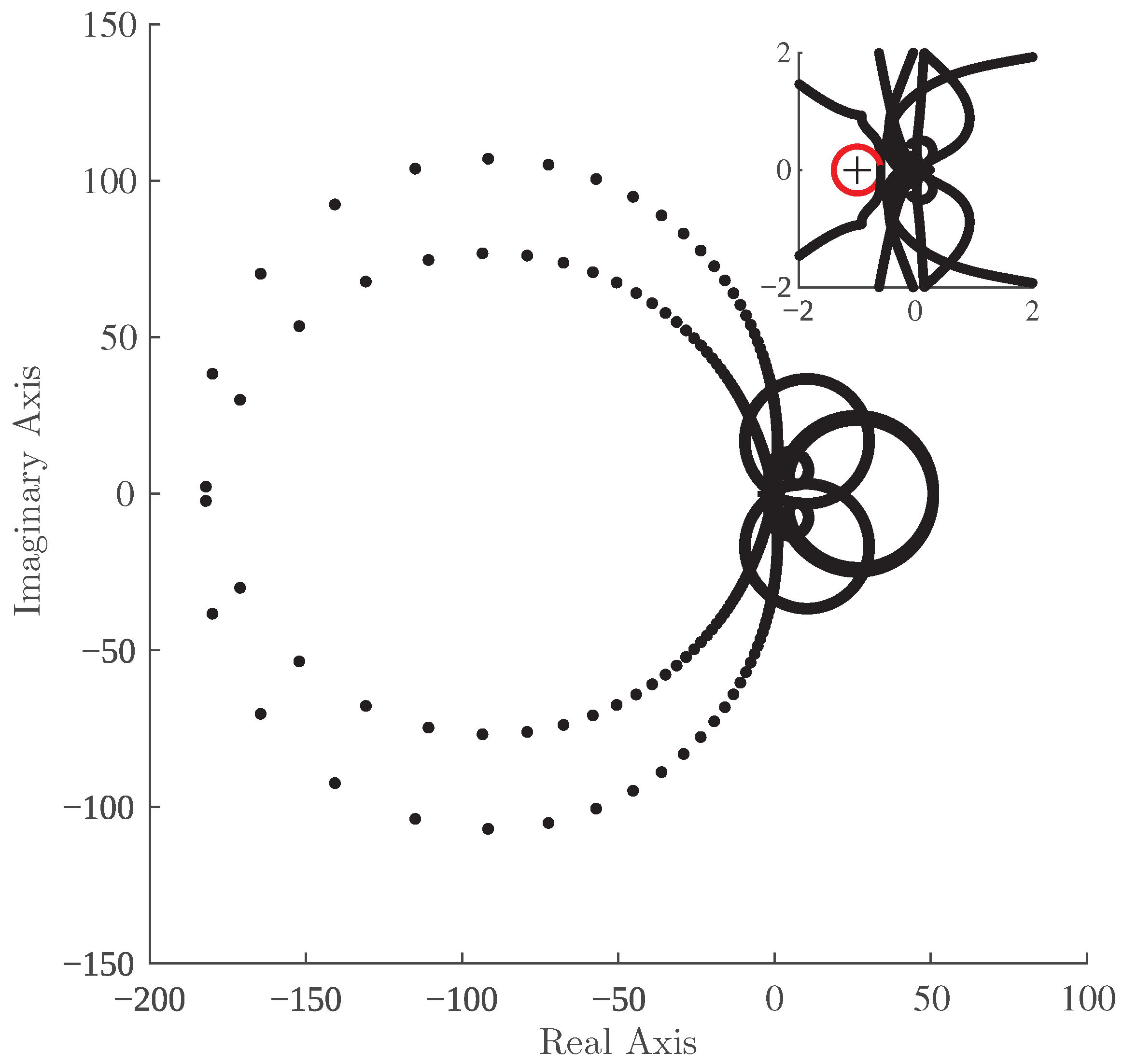
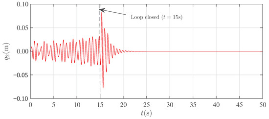
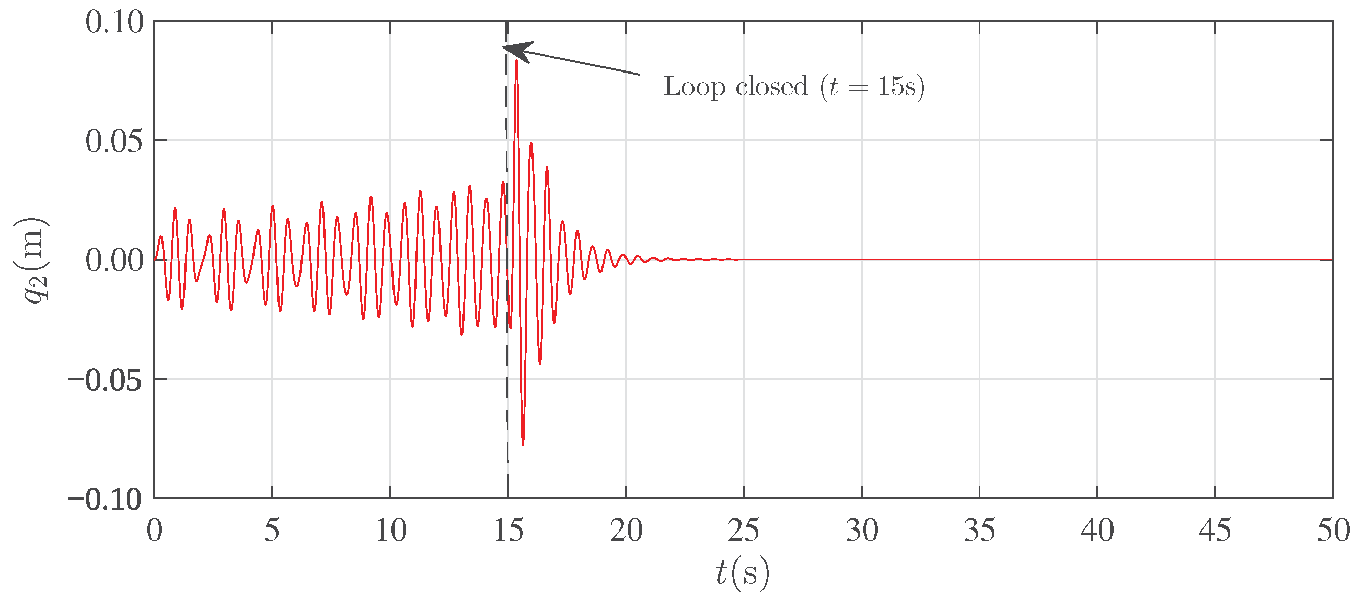
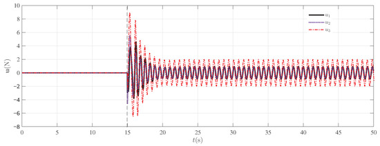
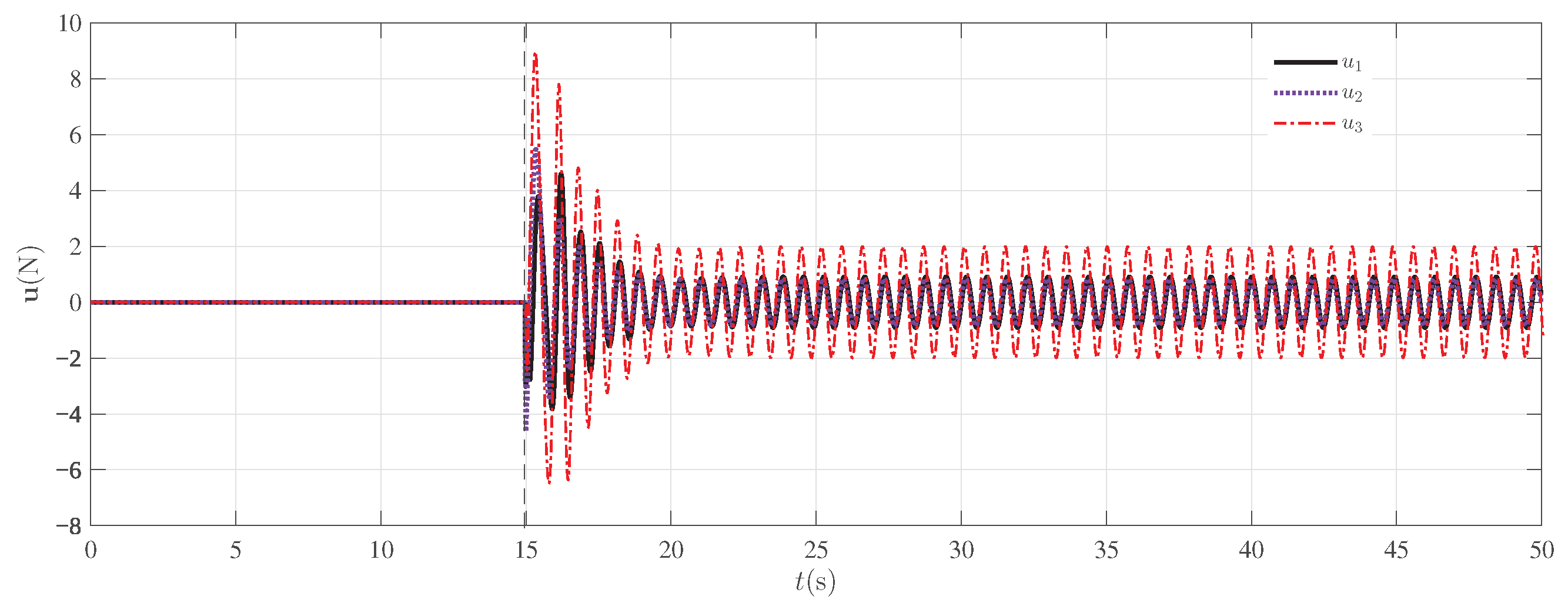
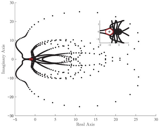
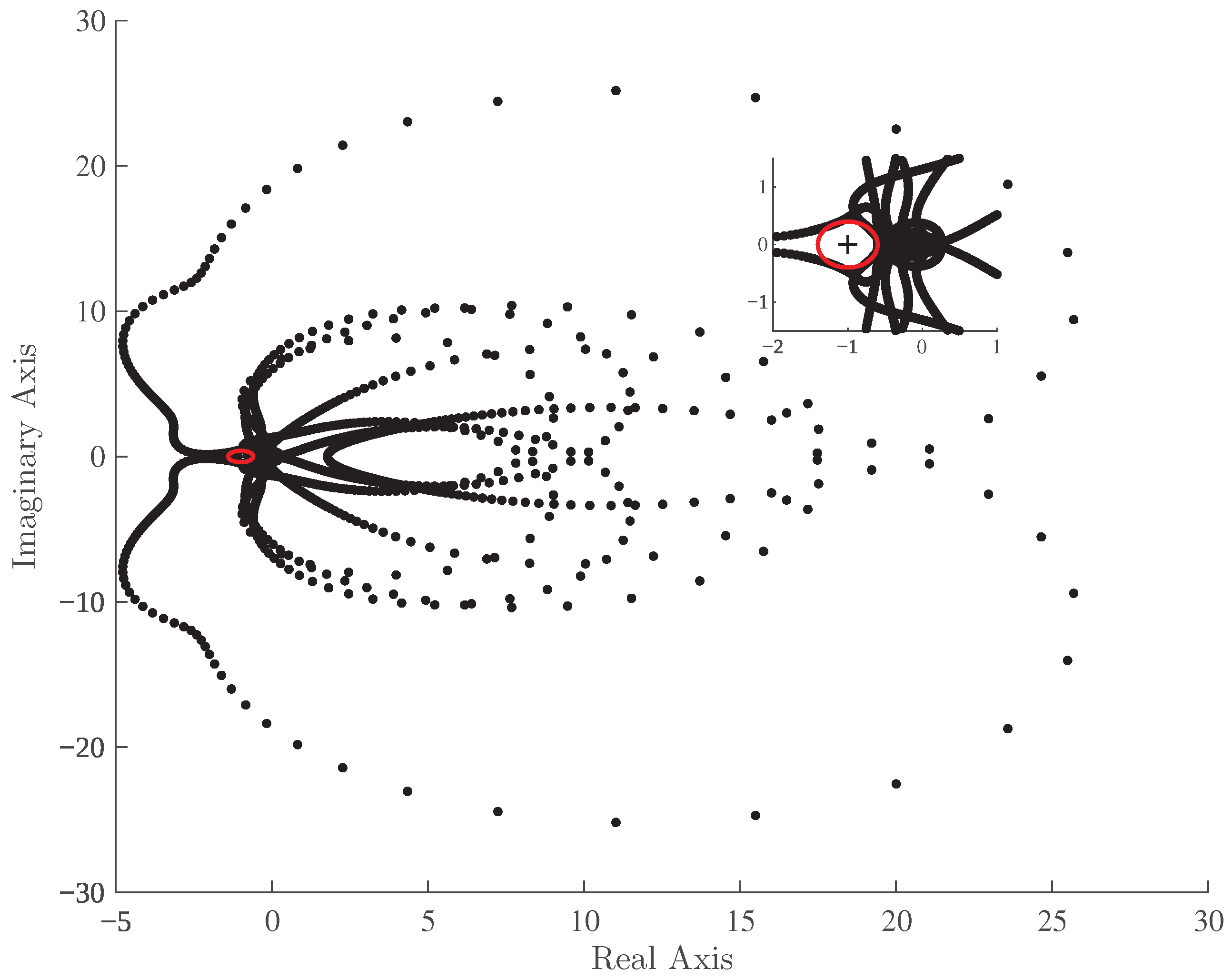
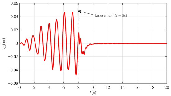
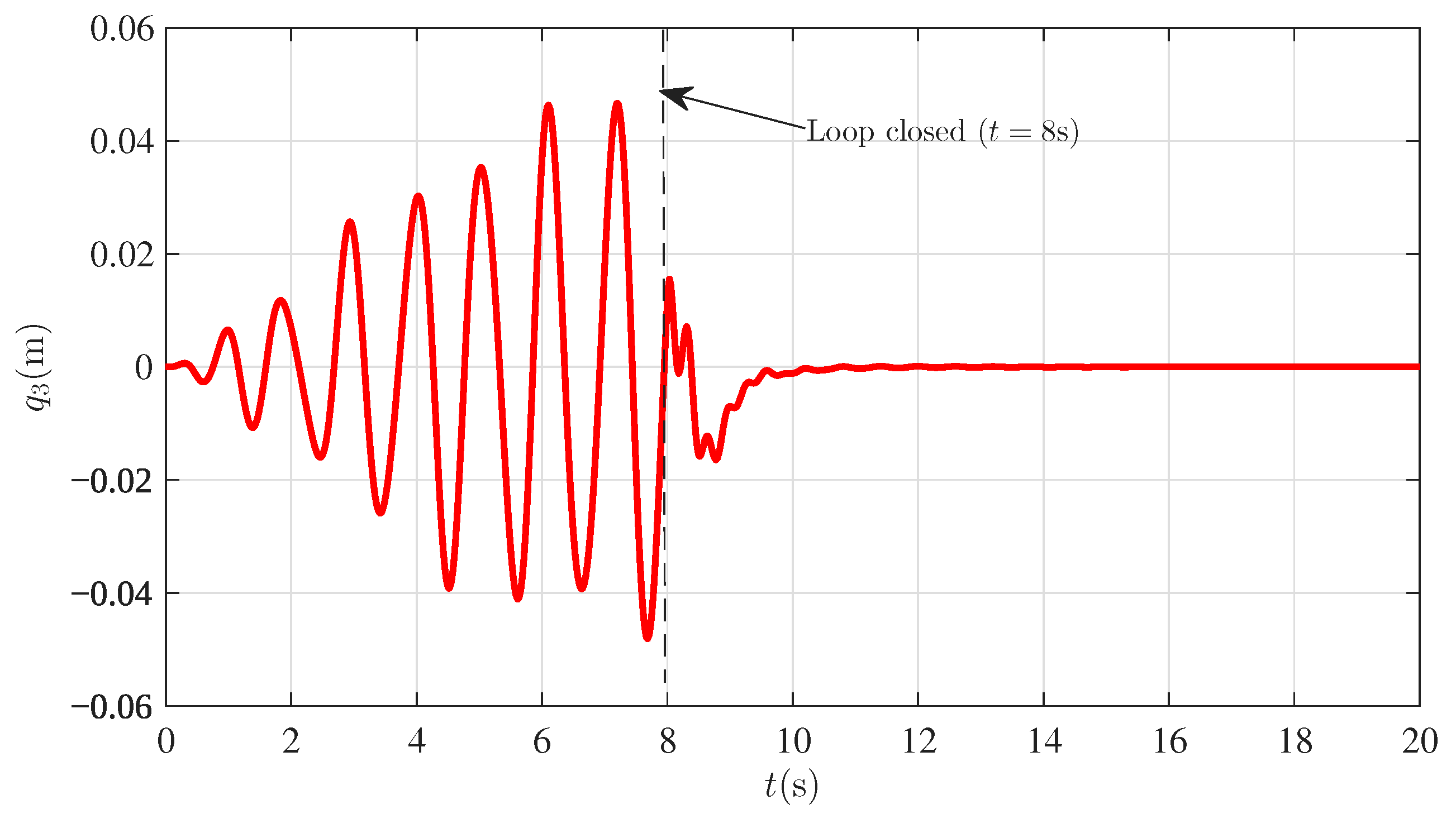
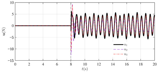
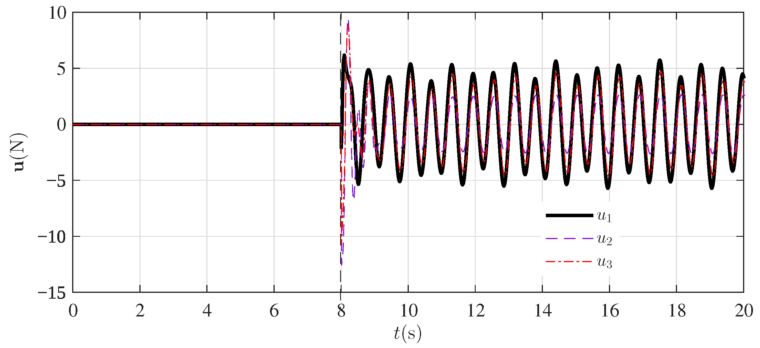
In Figure 7, the generalized Nyquist contour resulting from the computed controller is displayed, in full view and in detail. It is evident that the double crossing of the critical point of the complex plane corresponds to . A simulation in which the loop is closed at the instant was performed. The effectiveness of the controller can be checked in Figure 8, which shows the time-domain response of the target DOF, and in Figure 9, where the control effort delivered by the designed controller is depicted.
Figure 7.
Generalized Nyquist contour for the closed-loop system of the test case in Section 4.1.2.
Figure 8.
Time -domain response of the target DOF before and after loop closing.
Figure 9.
Control effort of test case in Section 4.1.2.
4.1.3. A Reduced Model of a Hospital Building
In this example, a reduced-order model of a four-DOF hospital building [36,37] is used for antiresonant design. A collocated sensor–actuator is used as in the case in Section 4.1.1. The system matrices are
Input delays are s, s, and s. The system is open-loop stable; that is, . A harmonic perturbation with two mixed frequencies , with and , enters the system in the first DOF, and the effect at the third DOF, that is, the cross inertance , must have two annihilator zero pairs and . Thus, one has
The disk for the margin definition has a value of . A stabilizing homogeneous solution is computed using the parameters
The feedback gain matrices are then computed, resulting in
In Figure 10, the generalized Nyquist contour resulting from the computed controller is displayed, in full view and in detail. It is evident there is no crossing of the critical point of the complex plane, corresponding to . A simulation in which the loop is closed at the instant was performed. The effectiveness of the controller can be checked in Figure 11, which shows the time-domain response of the target DOF, and in Figure 12, where the control effort delivered by the designed controller is depicted.
Figure 10.
Generalized Nyquist contour for the closed-loop system of the test case in Section 4.1.3.
Figure 11.
Time- domain response of the target DOF before and after loop closing.
Figure 12.
Control effort of test case in Section 4.1.3.
4.2. Robustness Margins
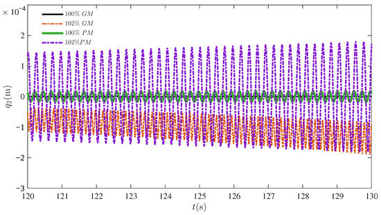
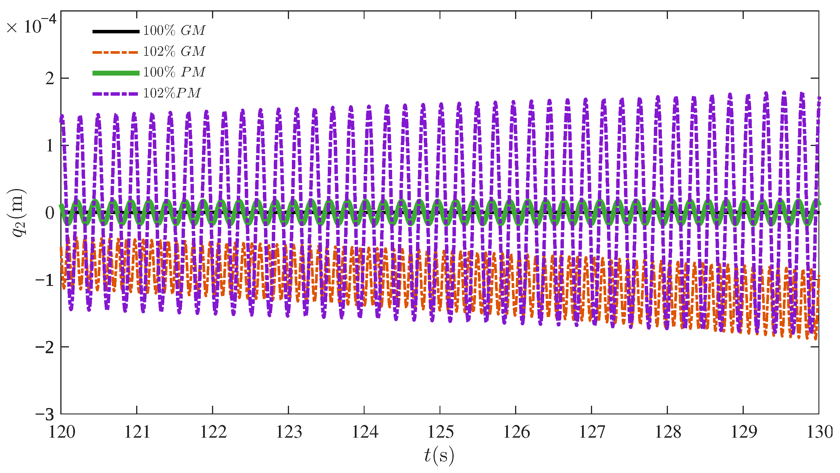
To illustrate the closed-loop system margins of the design described in Appendix A.2, the test case in Section 4.1.1 is stressed to the margins and slightly beyond them. The effective margins of the system were computed from the eigenloci as
To introduce the phase margin in the simulation, the critical frequency was identified as rad/s, resulting in a maximum additional delay in the loop of s. The simulations were run with no perturbations and an initial displacement of . The displacement of the target DOF is displayed in Figure 13. The system is resilient and exhibits marginal stability with of the computed margins, introduced once at a time. The uncertainty was increased beyond those values, leading to , and the closed-loop unstable behaviors were then noted.
Figure 13.
Closed-loop response of test case in Section 4.1.1 with gain and phase stressed at and beyond the margins.
4.3. Design Comparison
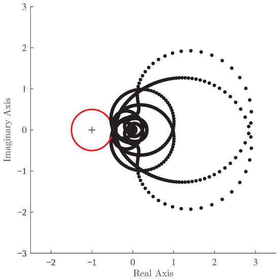
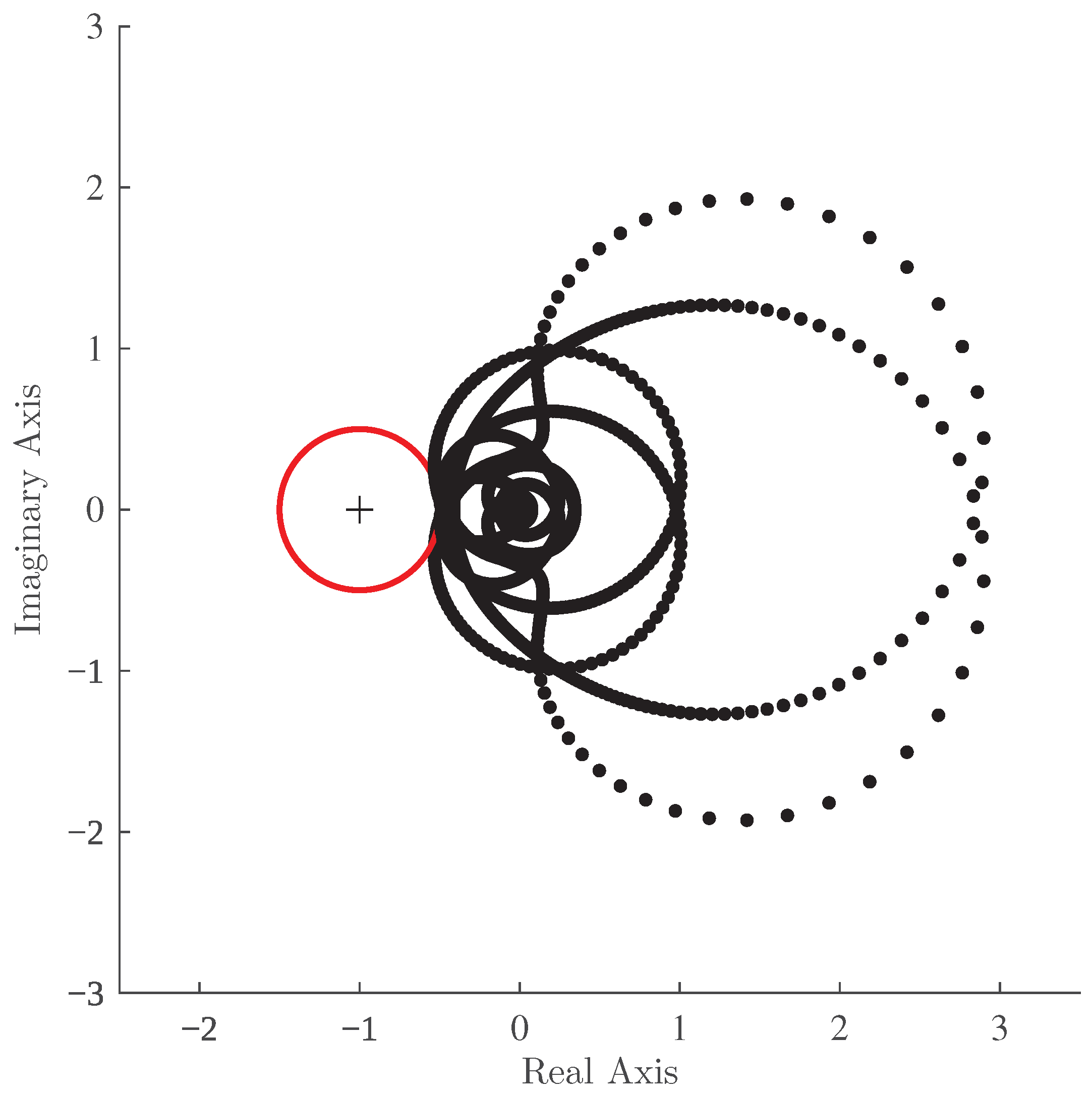
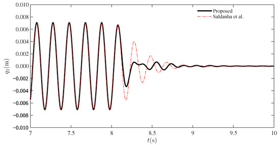
Consider the structural system of the test case in Section 4.1.1 and a antiresonant controller design with the same specifications as [26] for the output measurements, a silenced target DOF and the disturbance channel
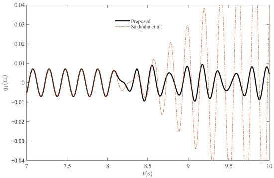
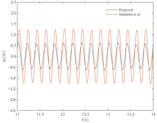
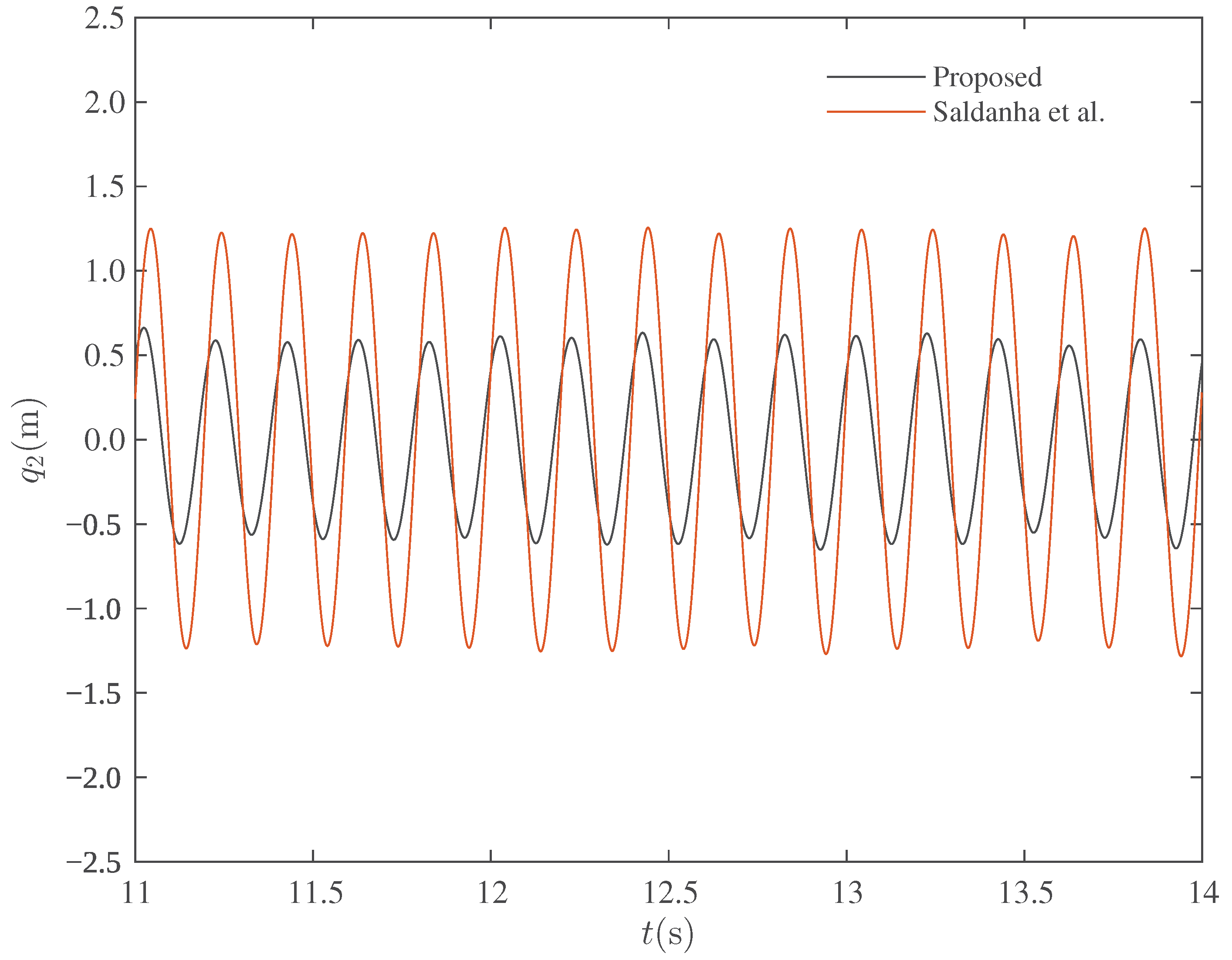
with and . The remaining matrices are the same as in the test case in Section 4.1.1; the delays are given as , and the disk for the margins is chosen with . In this case, , and thus the method to compute the homogeneous solution is conducted as described in Remark 1. The Nyquist contour forthe proposed mathod is displayed in Figure 14. The feedback matrices computed with the proposed method and with the method in [26] are displayed in Table 1. The system responses with the two controllers are then compared in two scenarios: the nominal system and the gain stressed with the loop gain scaled by the factor . Both the designs efficiently silence the output under the harmonic disturbance, as displayed in Figure 15. On the other hand, when the gain is stressed to the gain margin of the proposed approach, the controller shows resilience in assuring marginal stability, whereas the controller from [26] results in an unstable response, as illustrated in Figure 16.
Figure 14.
Generalized Nyquist contour for the closed-loop system of the test case in Section 4.3.
Table 1.
Feedback matrices for antiresonant control with designs using the methods of Saldanha et al. [26] and the proposed method.
Figure 15.
Comparison of time-domain responses of the structural system with antiresonant design and nominal system.
Figure 16.
Comparison of time-domain responses of the structural system with antiresonant design and maximum gain margin of the design with the proposed approach.
Another relevant comparison between the two methods regards the sensitivity of the closed-loop system to noise measurement that can plague the sensors. Notice that for the PD controller, the control law considering the estimated output , with being a stationary stochastic process representing the measurement noise, results in the transfer matrix from noise to output given by
On the other hand, the method proposed in [26] uses proper sensors to calculate the output velocity, resulting in it estimation as , with representing the velocity measurement noise. Denoting the measurement noise vector by , the transfer matrix for these two noise channels to the output in this case is given by
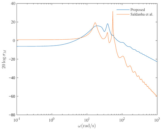
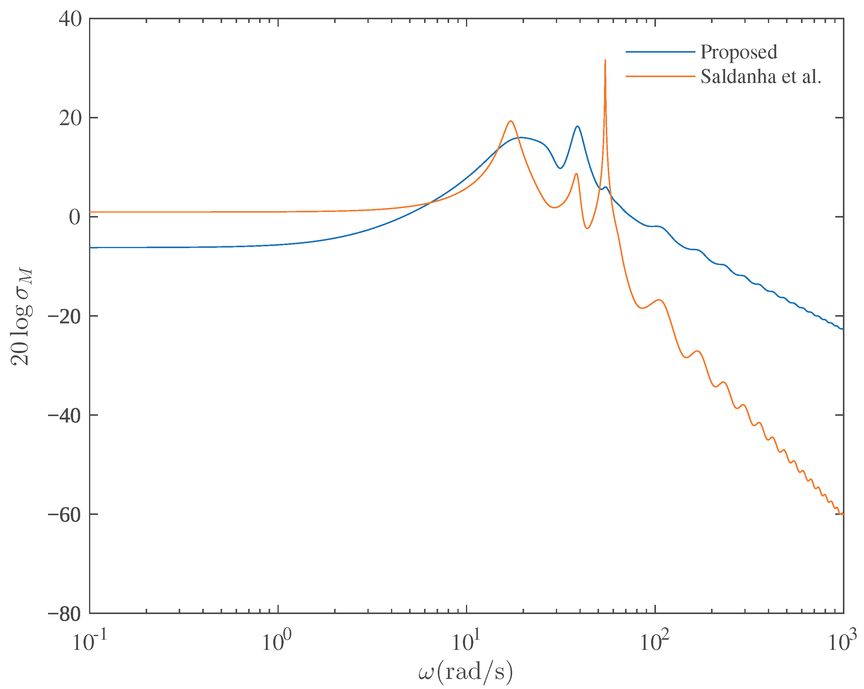
The frequency response for these transfer matrices (the maximum singular value) is displayed in Figure 17. The noise amplification is quite similar, with the proposed method performing slightly better (Figure 16, Figure 17 and Figure 18).
Figure 17.
Closed-loop frequency response of the two designs from noise to the output.
Figure 18.
Closed-loop system response in the time domain with white noise of variance (square meters in the displacement measurements and square meters by square seconds in the velocity measurements) red-colored by a low-pass filter—cutoff frequency 200 rad/s—at the measurements.
5. Discussion
The proposed approach to antiresonant control has been demonstrated to be effective in silencing the effect of harmonic perturbations entering the system on a given DOF. This is a better strategy for mitigating perturbations than the resonant-pole assignment design. Another relevant point is that, although in the examples the system matrices are known, the proposal can leverage experimental identification of the system receptance [17,38] and, subsequently, the dynamic stiffness matrix to handle the adjoint system for zero assignment. Moreover, the use of proportional–derivative output feedback further enhances the approach’s advantages, as only displacement sensors are required, whereas in [26], velocity measurements are used for feedback. Related to this work, the proposed approach can handle multiple perturbation frequencies rather than a single frequency as in [26]. The same can be said of the multiple delays considered here, whereas a single delay is explored in [26]. The approach may not perform well in some very specific cases. Some of these include systems with a reduced number of actuators and/or sensors. In these cases, the search space has a low dimension; that is, the number of free variables in the optimization problem may not be sufficient for attaining the minimum with constraint satisfaction.
6. Conclusions
This paper presented a novel systematic approach for designing PD output-feedback controllers to achieve antiresonance in second-order mechanical systems subjected to harmonic disturbances. By formulating the zero assignment problem as a pole assignment of an adjoint system, the method enables direct cancellation of harmonic components at target degrees of freedom. The proposed optimization framework integrates stability constraints via the Generalized Nyquist criterion and -disk robustness margins, with a Genetic Algorithm exploring the solution space.
The effectiveness of the methodology was demonstrated through a collection of numerical examples encompassing collocated and non-collocated configurations, stable and unstable open-loop systems, and multiple disturbance frequencies. Results confirm that stabilizing controllers enforcing antiresonance while ensuring robust stability margins can be systematically synthesized.
Future work will focus on experimental validation, extension to nonlinear systems, and integration with data-driven identification techniques to bypass explicit model requirements. Additionally, investigating adaptive schemes for time-varying disturbance frequencies and exploring alternative optimization algorithms may further enhance the practical applicability of the proposed approach.
Author Contributions
Conceptualization, J.M.A., J.R.B.d.A., N.J.B.D. and C.E.T.D.; methodology, J.M.A. and C.E.T.D.; software, J.M.A. and N.J.B.D.; validation, J.M.A., J.R.B.d.A., N.J.B.D. and C.E.T.D.; formal analysis, J.M.A. and C.E.T.D.; investigation, J.M.A., J.R.B.d.A., N.J.B.D. and C.E.T.D.; resources, J.M.A. and C.E.T.D.; data curation, J.M.A.; writing—original draft preparation, J.M.A., J.R.B.d.A., N.J.B.D. and C.E.T.D.; writing—review and editing, J.M.A. and C.E.T.D.; visualization, J.M.A.; supervision, J.M.A. and C.E.T.D.; project administration, J.M.A. and C.E.T.D.; funding acquisition, J.M.A. and C.E.T.D. All authors have read and agreed to the published version of the manuscript.
Funding
This research was funded by Conselho Nacional de Desenvolvimento Científico e Tecnológico—CNPq, grant numbers 311478/2022–0 and 306178/2023–0.
Data Availability Statement
The original contributions presented in this study are included in the article. Further inquiries can be directed to the corresponding author.
Conflicts of Interest
The authors declare no conflicts of interest.
Appendix A
Appendix A.1
The Lemma presented here can be found in [23], and the complete proof is presented in [27]. Let the loop function, as defined in Section 3.2, be
Assume that the characteristic equation has roots—open-loop poles—in the right half-plane. Setting , in which is the frequency, the Generalized Nyquist criterion can be met with the help of the following definitions.
Definition A1.
The eigenloci is the set of all the geometric branches, in the complex plane, obtained by computing the eigenvalues , when ω varies in the interval of frequencies , with .
Definition A2.
The number of counterclockwise encirclements of the point by the k-th branch of the eigenloci in the complex plane is denoted as .
Definition A3.
The number of counterclockwise encirclements of the point by the k-th branch of the eigenloci in the complex plane is denoted as .
Assumption A1.
The eigenloci of the loop function has no clockwise encirclements of the critical point ; that is, .
Lemma A1.
The closed-loop system in Equation (25) with Assumption 1 is exponentially stable if
- 1.
- ;
- 2.
- .
Appendix A.2. System Margins from the Nyquist Contour
For a controller design that assures the Nyquist contour remains outside the called disk, the following bounds for gain margin and phase margin can be certified for open-loop stable models [28]:
On the other hand, in the case of open-loop unstable systems, the margins have the bounds [29]
References
- Cheng, Y.; Dai, K.; Liu, Y.; Yang, H.; Sun, M.; Huang, Z.; Camara, A.; Yin, Y. A method for along-wind vibration control of chimneys by tuning liners. Eng. Struct. 2022, 252, 113561. [Google Scholar] [CrossRef] [Scilit]
- Menon, D.; Rao, P. Estimation of along-wind moments in RC chimneys. Eng. Struct. 1997, 19, 71–78. [Google Scholar] [CrossRef] [Scilit]
- Zeng, X.; Xu, J.; Han, B.; Zhu, Z.; Wang, S.; Wang, J.; Yang, X.; Cai, R.; Du, C.; Zeng, J. A Review of Linear Compressor Vibration Isolation Methods. Processes 2024, 12, 2210. [Google Scholar] [CrossRef] [Scilit]
- Liu, S.; Gu, C.; Tian, Q.; Huang, D.; Guo, Y. Research on the vibration mechanism of compressor complex exhaust pipeline based on transient flow. Int. J. Hydrogen Energy 2025, 139, 886–894. [Google Scholar] [CrossRef] [Scilit]
- Matin Nikoo, H.; Bi, K.; Hao, H. Passive vibration control of cylindrical offshore components using pipe-in-pipe (PIP) concept: An analytical study. Ocean. Eng. 2017, 142, 39–50. [Google Scholar] [CrossRef] [Scilit]
- Ding, H.; Ji, J.C. Vibration control of fluid-conveying pipes: A state-of-the-art review. Appl. Math. Mech. 2023, 44, 1423–1456. [Google Scholar] [CrossRef] [Scilit]
- Mottershead, J.E.; Ram, Y.M. Inverse eigenvalue problems in vibration absorption: Passive modification and active control. Mech. Syst. Signal Process. 2006, 20, 5–44. [Google Scholar] [CrossRef] [Scilit]
- Richiedei, D.; Trevisani, A. Simultaneous active and passive control for eigenstructure assignment in lightly damped systems. Mech. Syst. Signal Process. 2017, 25, 556–566. [Google Scholar] [CrossRef] [Scilit]
- Ikeda, Y. Active and semi-active vibration control of buildings in Japan – Practical applications and verification. Struct. Control Health Monit. 2009, 16, 703–723. [Google Scholar] [CrossRef] [Scilit]
- Dyke, S. Acceleration Feedback Control Strategies for Active and Semi-active Control Systems: Modeling, Algorithm Development, and Experimental Verification. Ph.D. Thesis, University of Notre Dame, Notre Dame, IN, USA, 1996. [Google Scholar]
- Ouyang, H.; Wei, X.; Mottershead, J.E. Structural modification and active vibration control by the receptance method: Review and tutorial. Mech. Syst. Signal Process. 2025, 241, 113532. [Google Scholar] [CrossRef] [Scilit]
- Ram, Y.; Singh, A.; Mottershead, J.E. State feedback control with time delay. Mech. Syst. Signal Process. 2009, 23, 1940–1945. [Google Scholar] [CrossRef] [Scilit]
- Araújo, J.M.; Dórea, C.E.; Gonçalves, L.M.; Datta, B.N. State derivative feedback in second-order linear systems: A comparative analysis of perturbed eigenvalues under coefficient variation. Mech. Syst. Signal Process. 2016, 76–77, 33–46. [Google Scholar] [CrossRef] [Scilit]
- Araújo, J.M. Discussion on ’State feedback control with time delay’. Mech. Syst. Signal Process. 2018, 98, 368–370. [Google Scholar] [CrossRef] [Scilit]
- Bernstein, D.S.; Bhat, S.P. Lyapunov Stability, Semistability, and Asymptotic Stability of Matrix Second-Order Systems. J. Mech. Des. 1995, 117, 145–153. [Google Scholar] [CrossRef] [Scilit]
- Araújo, J.M.; Castelan, E.d.B.; Dórea, C.E.T.; Isidório, I.D. A bilinear optimization-based approach for eigenstructure assignment output feedback control of second-order linear systems. Res. Sq. 2025, Preprints. [Google Scholar] [CrossRef] [Scilit]
- Mottershead, J.E.; Ram, Y.M. Receptance Method in Active Vibration Control. AIAA J. 2007, 45, 562–567. [Google Scholar] [CrossRef] [Scilit]
- Mottershead, J.E.; Tehrani, M.G.; James, S.; Ram, Y.M. Active vibration suppression by pole-zero placement using measured receptances. J. Sound Vib. 2008, 311, 1391–1408. [Google Scholar] [CrossRef] [Scilit]
- Singh, K.V. Active aeroelastic control with time delay for targeted flutter modes. Aerosp. Sci. Technol. 2015, 43, 281–288. [Google Scholar] [CrossRef] [Scilit]
- Yüksel, C.K.; Vyhlídal, T.; Bušek, J.; Hromčík, M.; Niculescu, S.I. A spectrum-based filter design for periodic control of systems with time delay. J. Sound Vib. 2025, 604, 118959. [Google Scholar] [CrossRef] [Scilit]
- Hirschfeldt, N.; Furtmüller, T.; Adam, C.; Maderebner, R. Compensated velocity feedback for non-collocated active vibration control. Meccanica 2024, 60, 3407–3427. [Google Scholar] [CrossRef] [Scilit]
- Richiedei, D.; Tamellin, I.; Trevisani, A. Pole-zero assignment by the receptance method: Multi-input active vibration control. Mech. Syst. Signal Process. 2022, 172, 108976. [Google Scholar] [CrossRef] [Scilit]
- Araújo, J.M.; Dantas, N.J.; Dórea, C.E.; Richiedei, D.; Tamellin, I. Pole-zero placement through the robust receptance method for multi-input active vibration control with time delay. J. Sound Vib. 2025, 599, 118850. [Google Scholar] [CrossRef] [Scilit]
- Araújo, J.M.; Bettega, J.; Dantas, N.J.B.; Dórea, C.E.T.; Richiedei, D.; Tamellin, I. Vibration Control of a Two-Link Flexible Robot Arm with Time Delay through the Robust Receptance Method. Appl. Sci. 2021, 11, 9907. [Google Scholar] [CrossRef] [Scilit]
- Dantas, N.J.B.; Dorea, C.E.T.; Araujo, J.M. Partial pole assignment using rank-one control and receptance in second-order systems with time delay. Meccanica 2021, 56, 287–302. [Google Scholar] [CrossRef] [Scilit]
- Saldanha, A.; Michiels, W.; Kuře, M.; Bušek, J.; Vyhlídal, T. Stability optimization of time-delay systems with zero-location constraints applied to non-collocated vibration suppression. Mech. Syst. Signal Process. 2024, 208, 110886. [Google Scholar] [CrossRef] [Scilit]
- Desoer, C.; Wang, Y.T. On the generalized nyquist stability criterion. IEEE Trans. Autom. Control 1980, 25, 187–196. [Google Scholar] [CrossRef] [Scilit]
- Skogestad, S.; Postlethwaite, I. Multivariable Feedback Control: Analysis and Design; Wiley: Hoboken, NJ, USA, 2005. [Google Scholar]
- Sebek, M.; Hurák, Z. An often missed detail: Formula relating peek sensitivity with gain margin less than one. In Proceedings of the 17th International Conference on Process Control ’09, Štrbské Pleso, Slovakia, 9–12 June 2009; pp. 1–9. [Google Scholar]
- Bernstein, D. Matrix Mathematics: Theory, Facts, and Formulas, 2nd ed.; Princeton Reference; Princeton University Press: Princeton, NJ, USA, 2009. [Google Scholar]
- Belotti, R.; Richiedei, D. Pole assignment in vibrating systems with time delay: An approach embedding an a-priori stability condition based on Linear Matrix Inequality. Mech. Syst. Signal Process. 2020, 137, 106396. [Google Scholar] [CrossRef] [Scilit]
- Nyquist, H. Regeneration theory. Bell Syst. Tech. J. 1932, 11, 126–147. [Google Scholar] [CrossRef] [Scilit]
- Baab, C.T.; Cockburn, J.C.; Latchman, H.A.; Crisalle, O.D. Generalization of the Nyquist robust stability margin and its application to systems with real affine parametric uncertainties. Int. J. Robust Nonlinear Control 2001, 11, 1415–1434. [Google Scholar] [CrossRef] [Scilit]
- Popp, K. Modelling and control of friction-induced vibrations. Math. Comput. Model. Dyn. Syst. 2005, 11, 345–369. [Google Scholar] [CrossRef] [Scilit]
- Liang, Y.; Yamaura, H.; Ouyang, H. Active assignment of eigenvalues and eigen-sensitivities for robust stabilization of friction-induced vibration. Mech. Syst. Signal Process. 2017, 90, 254–267. [Google Scholar] [CrossRef] [Scilit]
- Chahlaoui, Y.; Van Dooren, P. Benchmark Examples for Model Reduction of Linear Time-Invariant Dynamical Systems. In Dimension Reduction of Large-Scale Systems; Benner, P., Sorensen, D.C., Mehrmann, V., Eds.; Springer: Berlin/Heidelberg, Germany, 2005; pp. 379–392. [Google Scholar]
- Betcke, T.; Higham, N.J.; Mehrmann, V.; Schröder, C.; Tisseur, F. NLEVP: A Collection of Nonlinear Eigenvalue Problems. ACM Trans. Math. Softw. 2013, 39, 7. [Google Scholar] [CrossRef] [Scilit]
- Mottershead, J.E.; Tehrani, M.G.; James, S.; Court, P. Active vibration control experiments on an AgustaWestland W30 helicopter airframe. Proc. Inst. Mech. Eng. Part C J. Mech. Eng. Sci. 2012, 226, 1504–1516. [Google Scholar] [CrossRef] [Scilit]

Disclaimer/Publisher’s Note: The statements, opinions and data contained in all publications are solely those of the individual author(s) and contributor(s) and not of MDPI and/or the editor(s). MDPI and/or the editor(s) disclaim responsibility for any injury to people or property resulting from any ideas, methods, instructions or products referred to in the content. |
© 2026 by the authors. Licensee MDPI, Basel, Switzerland. This article is an open access article distributed under the terms and conditions of the Creative Commons Attribution (CC BY) license.