


Abstract
Ground source heat pump systems are prone to long-term ground thermal imbalance in severe cold regions because seasonal heat extraction considerably exceeds summer heat rejection. To address this issue, this study proposes a proton exchange membrane fuel cell-assisted ground source heat pump system with cascade waste heat recovery for a heating-dominated industrial building in Changchun, Northeast China. A TRNSYS-based dynamic simulation model was developed by coupling the building load, PEMFC stack, vertical ground heat exchanger, water-source heat pump, thermal storage tank, battery storage, circulation pumps, and coordinated control modules. The recovered PEMFC waste heat was preferentially used for space heating and thermal storage and was further allocated for ground-side thermal compensation when required. Annual and ten-year simulations were conducted to evaluate the effects of PEMFC integration on ground-side temperature, soil thermal balance, heat pump power consumption, and seasonal coefficient of performance. The simulated annual heating and cooling demands were 516,721 and 99,538 kWh, respectively, confirming the strongly heating-dominated load profile of the case building. Compared with the reference GSHP system, the PEMFC-assisted system reduced the annual soil temperature drop from 1.24 °C to 0.37 °C. Over ten years, the final average soil temperature increased from 7.29 °C to 9.95 °C, corresponding to a 52.1% reduction in cumulative soil temperature decline. In addition, the winter heat pump power range decreased from 15.76–39.94 kW to 12.33–28.90 kW, while the average heating-season COP increased from 4.68 to 5.21. These results demonstrate that PEMFC waste heat recovery can serve not only as an auxiliary heating source but also as an active ground thermal compensation mechanism, thereby improving the long-term thermal sustainability and operational performance of GSHP systems in severe cold regions.
1. Introduction
The transition toward low-carbon and high-efficiency energy systems has become a central requirement for industrial parks, especially in regions with long heating periods and severe winter climates [1]. In severe cold regions, industrial buildings usually exhibit a highly heating-dominated load profile because of large indoor–outdoor temperature differences, long heating durations, and considerable envelope heat losses [2,3,4]. Large-span industrial buildings further intensify this challenge due to their large indoor volume, high spatial thermal inertia, and stringent requirements for stable indoor thermal environments [5,6]. Therefore, developing clean heating systems that can simultaneously ensure high energy efficiency, operational reliability, and long-term thermal stability is of great significance for industrial decarbonization in severe cold regions.
Ground source heat pump systems have been widely applied as clean heating and cooling technologies because they utilize shallow geothermal energy with relatively stable temperature characteristics. Compared with conventional fossil-fuel-based heating systems, GSHP systems can substantially improve heating efficiency by extracting low-grade heat from the ground and upgrading it through a vapor-compression cycle. However, the long-term performance of GSHP systems is strongly constrained by the thermal balance of the ground heat exchanger. In heating-dominated regions, the heat extracted from the ground during winter is generally much greater than the heat rejected into the ground during summer [6,7,8,9,10]. This seasonal mismatch causes a continuous decrease in soil temperature, a reduction in the evaporator inlet temperature of the heat pump, increased compressor power consumption, and eventual deterioration of the coefficient of performance. Consequently, soil thermal imbalance has become one of the key obstacles to the sustainable operation of GSHP systems in severe cold regions.
Considerable research has been conducted to understand and mitigate the soil thermal imbalance of GSHP systems. Existing studies have shown that the thermal imbalance ratio of the ground is closely related to building type, climatic condition, load profile, borehole configuration, and long-term operation strategy [3,11,12]. For heating-dominated buildings, the continuous decline in soil temperature can seriously reduce heating performance and even threaten the long-term reliability of the entire system. To address this issue, hybrid ground source heat pump systems have been proposed, in which auxiliary heat sources or heat rejection devices are incorporated to compensate for seasonal ground heat deficits [13,14,15,16]. Typical approaches include solar-assisted ground heat regeneration, cooling-tower-assisted heat rejection, boiler-assisted heating, waste heat injection, and seasonal thermal storage [9]. These strategies can improve ground thermal recovery to different extents; however, solar-assisted systems are limited by intermittency and climatic dependence, cooling towers mainly address cooling-dominated conditions, and conventional auxiliary heating may increase fossil energy consumption [17,18,19]. Therefore, stable and low-carbon waste heat sources are increasingly considered promising candidates for active ground thermal compensation.
Proton exchange membrane fuel cells provide a promising pathway for hydrogen-based distributed energy supply because they can directly convert hydrogen chemical energy into electricity with high efficiency, low noise, and low local emissions [20,21,22,23]. During operation, Proton Exchange Membrane Fuel Cell (PEMFC) stacks also generate a considerable amount of low- to medium-grade heat that must be removed by an effective thermal management system to maintain the stack within its optimal operating temperature range. If this heat is dissipated directly to the ambient environment, a substantial portion of the hydrogen energy input is wasted. Conversely, if PEMFC waste heat is recovered and utilized through cascade energy management, the PEMFC can operate not only as a power generation unit but also as a controllable thermal source for combined heat and power systems [22,23,24,25]. In building energy applications, PEMFC-based Combined Heat and Power (CHP) systems have been investigated for improving primary energy efficiency, reducing greenhouse gas emissions, and enhancing distributed energy autonomy.
Recent studies on PEMFC waste heat recovery have focused on thermal management, cogeneration, trigeneration, and integration with auxiliary energy conversion devices such as heat pumps, absorption chillers, and organic Rankine cycles. These studies have demonstrated that PEMFC waste heat can be used for domestic hot water, space heating, cooling generation, or efficiency enhancement of heat pump systems. In particular, coupling PEMFCs with heat pumps is attractive because PEMFC electricity can partially cover the electrical demand of the heat pump, while PEMFC waste heat can reduce the thermal load assigned to the heat pump or improve the heat pump source-side operating condition [26,27]. Such coupling creates a dual benefit: electrical self-supply and thermal recovery. Nevertheless, most existing PEMFC-heat pump studies primarily focus on short-term thermodynamic performance, energy efficiency, or economic evaluation, while the interaction between PEMFC waste heat and the long-term thermal evolution of the ground heat exchanger remains insufficiently clarified.
From the perspective of multi-energy system operation, a PEMFC-assisted GSHP system has a more complex coupling mechanism than a conventional CHP or heat pump system. The electrical output of the PEMFC can be used to drive the heat pump, circulation pumps, or building electrical loads; the recovered waste heat can be stored in a thermal tank, supplied directly to the building, or injected into the ground-side loop for soil thermal regeneration; and the heat pump performance is influenced by both building load variation and ground-side temperature evolution. Therefore, the system performance is governed by the dynamic interaction among building demand, PEMFC heat–electric output, thermal storage, heat pump operation, and ground thermal balance. Without an appropriate coordinated control strategy, excessive PEMFC operation may cause thermal mismatch, while insufficient waste heat recovery may fail to alleviate soil temperature decline [28,29,30]. It is therefore necessary to develop a dynamic modeling and control framework that can quantify the coupled thermal-electrical behavior of the system over both annual and long-term operation periods.
Although the separate technologies of GSHP systems, PEMFC-CHP systems, and hybrid heat pump systems have been widely studied, several research gaps remain. First, previous GSHP studies have mainly addressed soil thermal imbalance through borehole optimization, auxiliary heat sources, or seasonal heat storage, but the use of PEMFC waste heat as an active and controllable ground thermal compensation source has received limited attention. Second, existing PEMFC-CHP studies have mainly emphasized electrical efficiency, waste heat recovery efficiency, or building-level energy supply, while the effect of PEMFC waste heat on long-term soil temperature recovery in GSHP systems has rarely been quantified. Third, the coupled influence of ground heat exchanger design parameters and PEMFC operating parameters on seasonal energy performance, heat pump power consumption, and long-term soil thermal stability is still unclear. Finally, a coordinated control framework that integrates indoor thermal demand, PEMFC operation, heat pump activation, thermal storage, and ground temperature constraints remains insufficiently developed for severe cold regions.
To address these gaps, this study proposes a PEMFC-assisted ground source heat pump system with cascade waste heat recovery for an industrial building in a severe cold region. The system integrates a PEMFC subsystem, a ground source heat pump subsystem, a vertical ground heat exchanger, a thermal storage tank, an electrical storage unit, circulation pumps, and building load terminals. A dynamic simulation model is established by coupling the building load model, PEMFC stack model, ground heat exchanger model, heat pump model, auxiliary component models, and control modules. Annual and ten-year simulations are conducted to evaluate the influence of PEMFC waste heat recovery on ground heat exchanger temperature, soil thermal balance, heat pump power consumption, and seasonal COP. In addition, parametric analyses are performed to investigate the effects of borehole depth, U-tube configuration, borehole radius, circulating flow velocity, PEMFC active area, stack number, and hydrogen pressure on system performance. The main contributions of this study are as follows. First, a PEMFC-assisted GSHP system with cascade waste heat recovery is developed for heating-dominated industrial buildings in severe cold regions. Second, the long-term mechanism by which PEMFC waste heat mitigates soil thermal imbalance is quantified through annual and ten-year dynamic simulations. Third, the heat–electric coupling relationship among PEMFC output, heat pump power consumption, source-side temperature recovery, and system COP is clarified. Fourth, the sensitivity of key ground heat exchanger and PEMFC parameters is systematically analyzed to identify dominant design and operation factors. Finally, a coordinated control concept is proposed to regulate PEMFC operation, heat pump activation, thermal storage, and seasonal operation modes, providing a theoretical basis for hydrogen-based clean heating systems in severe cold industrial parks.
2. System Description
2.1. Case Building and Climatic Boundary Conditions
The proposed PEMFC-assisted ground source heat pump system was evaluated using a large-space industrial building located in Changchun, Northeast China. Changchun is a typical severe cold region characterized by a long heating season, low winter outdoor temperature, and pronounced seasonal mismatch between heating and cooling demands. These climatic features make the case suitable for investigating whether PEMFC waste heat recovery can mitigate long-term ground thermal imbalance in heating-dominated GSHP systems. The case building is a Class-A industrial workshop with dimensions of 60 m × 24.2 m × 17.5 m (see the architectural model in Figure 1). The indoor design temperature was set to 18 °C during the heating season and 26 °C during the cooling season. The corresponding indoor relative humidity values were 40% and 60%, respectively. Internal heat gains from occupants, lighting, and equipment were included in the building load simulation. The occupant density was set to 20 m2 per person, while the lighting and equipment power densities were 10 W/m2 and 30 W/m2, respectively. Typical meteorological year data for Changchun were used as the climatic boundary conditions; the annual variations of outdoor dry-bulb and wet-bulb temperatures, along with the total horizontal solar radiation intensity, are illustrated in Figure 2. The hourly outdoor dry-bulb temperature, wet-bulb temperature, and horizontal solar radiation were imported into the building simulation model to calculate the dynamic heating and cooling loads. The climatic and building design parameters used in this case study are summarized in Table 1.
Figure 1.
SketchUp architectural model diagram.
Figure 2.
Changchun typical (a) annual outdoor dry-bulb and wet-bulb temperature (b) annual total horizontal solar radiation intensity.
Table 1.
Climatic and building design parameters used in the case study.
2.2. Reference Ground Source Heat Pump System
A conventional ground source heat pump system was established as the reference system to evaluate the performance enhancement achieved by PEMFC integration. The schematic diagram of this system is presented in Figure 3. The reference system consists of a vertical ground heat exchanger, a water-source heat pump unit, a ground-side circulation pump, a load-side circulation pump, and building terminal units. The system contains two closed hydraulic loops: the ground-side loop and the load-side loop. In the ground-side loop, the circulating fluid is driven by the ground-side pump and enters the vertical borehole heat exchanger, where heat is exchanged with the surrounding soil. During the heating season, heat is extracted from the ground and supplied to the evaporator side of the heat pump. During the cooling season, the heat rejected by the building is transferred into the ground through the same borehole field. In the load-side loop, the circulating water exchanges heat with the condenser or evaporator side of the heat pump and then supplies heating or cooling to the building terminal. This conventional GSHP configuration provides the baseline for quantifying the effects of PEMFC waste heat recovery on source-side temperature, heat pump power consumption, coefficient of performance, and long-term soil temperature evolution.
Figure 3.
Schematic diagram of the reference ground source heat pump system.
2.3. PEMFC-Assisted Ground Source Heat Pump System
On the basis of the reference GSHP system, a PEMFC subsystem was introduced to construct a multi-energy coupled heat and power supply system. The schematic diagram of the proposed system is illustrated in Figure 4. It consists of a PEMFC stack, hydrogen storage unit, air supply unit, cooling loop, heat exchanger, thermal storage tank, battery storage unit, inverter, GSHP vertical ground heat exchanger, circulation pumps, and building terminals. The system is designed to recover both the electrical and thermal outputs of the PEMFC and coordinate them with the heat pump and ground heat exchanger. The system employs the thermal storage tank temperature as the core decision variable. When , the recovered waste heat from the PEMFC alone can satisfy the building heating load; the controller then issues a shutdown command to the GSHP, and the building terminals are supplied directly by the thermal storage tank. If the tank temperature continues to rise and reaches 50 °C, the PEMFC is also shut down to prevent overheating. When , the PEMFC waste heat is insufficient to meet the full heating demand; the controller starts the GSHP, and the return water from the tank is first raised in temperature by the heat pump before being sent back to the tank, with the two heat sources operating in series. When , if the PEMFC is not yet running, it is started as a priority; if it is already running but still cannot maintain the tank temperature, the GSHP is started simultaneously, and both supply heat to the tank jointly. In terms of valve control, a combination of diverter valves and mixing valves is arranged to regulate the flow direction of the PEMFC cooling water according to the tank temperature. When , the cooling water is bypassed to the cooling circuit; when the temperature is between 35 and 50 , the cooling water is fully directed to the plate heat exchanger for waste heat recovery. The mixing valve maintains the supply water temperature entering the tank stable by adjusting the bypass flow rate. At the power dispatch level, the DC power generated by the PEMFC is converted to AC via the inverter and supplied to the heat pump compressor, circulating pumps, and building electrical loads. When the power generation exceeds the instantaneous demand, the surplus electricity is stored in the battery; when the electrical load exceeds the PEMFC output, the battery discharges to supplement the shortfall, thereby smoothing transient mismatches between generation and demand. Furthermore, the strategy of prioritizing PEMFC waste heat utilization during the heating season effectively reduces the intensity of heat extraction from the soil, helps mitigate soil cold accumulation under long-term operation, and maintains the seasonal thermal balance of the GSHP system. Through the above control logic, the system achieves multi-energy coordinated operation among fuel cell waste heat, GSHP, electrical energy storage, and building loads, ensuring cascade utilization of thermal energy, power supply-demand balance, and long-term thermal stability on the ground side under various operating conditions.
Figure 4.
Schematic diagram of the PEMFC-assisted GSHP system with cascade waste heat recovery.
2.4. TRNSYS-Based Component Representation
The coupled system was implemented in TRNSYS (Transient System Simulation Program, Version 18.0) using a modular modeling approach. Each physical component was represented by a corresponding simulation module, and the energy and mass flows among modules were connected to form an integrated dynamic simulation platform. The reference GSHP system was mainly composed of the ground heat exchanger, heat pump, circulation pumps, building load module, and control units. The PEMFC-assisted system further included the fuel cell module, hydrogen supply module, thermal storage tank, inverter, and battery storage unit. The main TRNSYS modules employed in this study and their corresponding physical functions are summarized in Table 2.
Table 2.
Main TRNSYS modules and their physical functions in the coupled system.
2.5. Key Design Parameters of the Coupled System
The main parameters of the GSHP subsystem, PEMFC subsystem, circulation pumps, and thermal storage tank are summarized in Table 3. These parameters define the baseline operating condition for annual and long-term dynamic simulations. The GSHP subsystem was configured with 63 boreholes, each with a depth of 100 m. The borehole field was modeled with double U-tubes, and water was used as the circulating fluid. The PEMFC subsystem was represented by a stack model with specified cell number, stack number, membrane thickness, operating temperature, and total current. The thermal storage tank was incorporated to decouple PEMFC heat generation from building heat demand. The specific configurations of these key components are detailed in Table 3.
Table 3.
Main design parameters of the PEMFC-assisted GSHP system.
2.6. Energy Flow Organization and Cascade Waste Heat Recovery
The proposed system is characterized by the coordinated organization of hydrogen energy, electrical energy, recovered heat, and shallow geothermal energy. Hydrogen is first converted into electricity and heat in the PEMFC stack. The electrical output is supplied to the heat pump, circulation pumps, auxiliary devices, and building electrical loads through the inverter. The battery is used to balance short-term fluctuations between PEMFC generation and load demand. The thermal output of the PEMFC is recovered by the stack cooling loop and transferred to the thermal storage tank. Because PEMFC waste heat is available at a higher temperature level than the shallow ground source, it is prioritized in the heating process. When the storage tank temperature satisfies the building-side heating requirement, the recovered heat is directly supplied to the building. When the recovered heat is insufficient, the GSHP provides supplementary heat by extracting low-grade heat from the ground and upgrading it through the heat pump cycle. This cascade utilization strategy allows medium-temperature PEMFC waste heat to be used before low-grade ground heat is upgraded, thereby reducing unnecessary compressor work. In addition, PEMFC waste heat can be used to compensate for ground-side heat deficits in heating-dominated operation. In severe cold regions, the ground heat exchanger is subject to long-term cooling because winter heat extraction is greater than summer heat rejection. By introducing PEMFC waste heat into the coupled thermal loop, the source-side temperature of the heat pump can be improved and the decline in soil temperature can be slowed. Therefore, PEMFC waste heat serves not only as a recovered energy source but also as an active thermal compensation source for long-term ground thermal balance.
2.7. Seasonal Operation Modes
The proposed system operates under different seasonal modes to match the heating and cooling demand of the industrial building. These operational modes are systematically summarized in Table 4. In the heating season, the PEMFC and GSHP operate cooperatively. PEMFC waste heat is preferentially recovered and stored in the thermal tank. When the recovered heat is sufficient, it is directly used for space heating; otherwise, the GSHP is activated to provide supplementary heating. This mode reduces the ground heat extraction intensity and improves the source-side operating condition of the heat pump. In the cooling season, the GSHP operates in cooling mode to remove heat from the building and reject it to the ground. The PEMFC can be operated under two alternative strategies. Under the continuous-operation strategy, the PEMFC continues to generate electricity, and its recovered heat is used for domestic hot water or stored for later use. Under the summer-shutdown strategy, the PEMFC remains inactive during the cooling period to reduce unnecessary heat generation and ground thermal disturbance. The comparison of these two strategies provides a basis for evaluating the trade-off among system energy efficiency, peak power demand, and soil thermal recovery. During transition seasons, the building thermal load is relatively low and intermittent. The heat pump is activated only when the indoor temperature deviates from the set point, while the PEMFC and battery are used to stabilize the electrical subsystem. The thermal storage tank buffers the mismatch between PEMFC heat generation and building heat demand. This seasonal operation logic provides the basis for the coordinated control strategy developed in the following sections.
Table 4.
Seasonal operating modes of the PEMFC-assisted GSHP system.
3. Model Development
3.1. General Modeling Framework
The following assumptions were adopted to simplify the dynamic simulation:
- (I)
- The circulating fluid in the ground-side and load-side loops was treated as incompressible water with constant thermophysical properties [1].
- (II)
- Heat losses in short connecting pipes were neglected compared with the heat exchange in the heat pump, storage tank, PEMFC cooling loop, and ground heat exchanger [1].
- (III)
- The PEMFC stack was assumed to operate uniformly, and all cells in the stack were considered to have identical operating conditions [2].
- (IV)
- Hydrogen supplied to the anode was assumed to be pure, while the cathode gas was treated as an air mixture containing oxygen and nitrogen [2].
- (V)
- The heat generated by the PEMFC was recovered through the stack cooling loop, and the stack was assumed to be thermally well insulated except for the designed heat recovery pathway [2].
- (VI)
- The building load was calculated dynamically according to the climatic boundary conditions and indoor temperature control set points [3].
3.2. Building Load Model
Model Assumptions and Boundary Conditions:
The following key assumptions were adopted in the simulation models:
- (1)
- Steady-state operation for component-level calculations within each time step;
- (2)
- Ideal gas behavior for hydrogen and oxygen;
- (3)
- Uniform temperature distribution within each control volume;
- (4)
- Constant thermophysical properties of working fluids;
- (5)
- Negligible heat losses in connecting pipelines.
Boundary Conditions:
Ground heat exchanger: Inlet temperature sequence from TRNSYS simulation, initial soil temperature 12.4 °C;
PEMFC stack: Operating temperature range 60–80 °C, hydrogen pressure 1.5 atm, oxygen pressure 1.0 atm;
Heat pump: Evaporator/condenser water temperature range 5–35 °C;
Thermal storage tank: Initial temperature 20 °C, ambient temperature from weather data.
The heating and cooling demand of the building was calculated according to the indoor set-point temperature, outdoor meteorological data, envelope heat transfer, and internal heat gains from occupants, lighting, and equipment. In the heating season, the system was activated when the indoor temperature was lower than 18 °C. In the cooling season, the system was activated when the indoor temperature was higher than 26 °C. The heating season was defined from January 1 to April 6 and from October 20 to December 31, while the cooling season was defined from July 1 to September 30. In TRNSYS, the dynamic load was applied to the water loop through the building load module. The outlet temperature of the load-side fluid was determined from the thermal balance: [1]
where Tout and Tin are the inlet and outlet temperatures of the load-side fluid, respectively; Qload is the instantaneous building heating or cooling load; m is the mass flow rate; and cp is the specific heat capacity of the circulating fluid.
3.3. Ground Heat Exchanger Model
In the dynamic simulation, the ground heat exchanger was represented by a vertical borehole heat exchanger model based on finite cylindrical heat source theory. The model accounts for the transient heat transfer between the circulating fluid, U-tube wall, grout, borehole, and surrounding soil. The outlet temperature of the ground-side fluid was calculated from the instantaneous heat exchange rate:
where Qg is the heat exchange rate between the ground-side loop and soil, mg is the ground-side mass flow rate, and Tg,in and Tg,out are the inlet and outlet temperatures of the ground heat exchanger, respectively. During heating operation, Qg represents heat extracted from the ground; during cooling operation, it represents heat rejected to the ground.
The average soil temperature was tracked during annual and long-term simulations to evaluate the thermal imbalance of the ground heat exchanger. The soil temperature variation was used as the main indicator for determining whether PEMFC waste heat recovery could mitigate long-term ground cooling in the heating-dominated region.
3.4. PEMFC Stack Model
is the number of stacks [7].
The hydrogen consumption rate is calculated by Faraday’s law:
The heat generation rate of the PEMFC is calculated as:
where is the lower heating value of hydrogen. The above equations form the PEMFC stack model used to determine the cell voltage, stack voltage, electrical power, hydrogen consumption, and recoverable waste heat [7].
3.5. Heat Pump Model
The water-source heat pump was used to transfer heat between the ground-side loop and the load-side loop. The heat pump operates in heating mode during winter and cooling mode during summer. In heating mode, the coefficient of performance is defined as:
where is the heating coefficient of performance, is the heating capacity supplied to the load side, and is the heat pump power consumption in heating mode [13].
The heat absorbed from the ground-side source in heating mode is:
The condenser-side outlet temperature is determined by:
where and are the inlet and outlet temperatures of the condenser-side water, respectively, and is the condenser-side mass flow rate.
In cooling mode, the cooling coefficient of performance is defined as [13]
where is the cooling capacity and is the heat pump power consumption in cooling mode. The heat rejected to the ground side is:
Accordingly, the heat pump model links the building load, ground-side temperature, and compressor power consumption. An increase in the ground-side inlet temperature during heating mode improves the operating condition of the heat pump and reduces compressor power consumption. Therefore, PEMFC waste heat compensation can enhance heat pump performance by both reducing the load assigned to the heat pump and improving its source-side thermal condition.
3.6. Circulation Pump Model
In this study, constant-speed pumps were adopted. Therefore, the pump power remained constant during operation once the pump was activated. The total auxiliary pump power was calculated as:
where and are the rated powers of the ground-side pump and load-side pump, respectively.
3.7. Thermal Storage Tank Model
The thermal storage tank was used to decouple PEMFC waste heat generation from building thermal demand. The tank receives heat from the PEMFC cooling loop through a heat exchanger and supplies heat to the building-side loop or the ground-side compensation pathway according to the control strategy.
The energy balance of the storage tank can be expressed as:
where is the mass of water in the tank, is the average tank temperature, is the heat input from PEMFC waste heat recovery, is the heat supplied to the building or ground-side loop, and is the heat loss from the tank to the ambient environment.
The heat loss from the storage tank was calculated as:
where is the overall heat loss coefficient, is the surface area of the tank, and is the ambient temperature. In the TRNSYS model, the thermal storage tank was represented by a stratified tank model, allowing the temporal mismatch between PEMFC heat generation and building heat demand to be considered.
3.8. Battery Storage and Electrical Balance Model
The battery storage unit was introduced to stabilize the electrical subsystem. The PEMFC electrical output varies with operating current and stack condition, while the electrical demand of the heat pump, circulation pumps, and building loads fluctuates with time. The battery absorbs surplus PEMFC electricity when generation exceeds demand and discharges when the instantaneous electrical demand is greater than the PEMFC output. The electrical power balance of the system can be expressed as:
where is the PEMFC electrical output, is the battery discharge power, is the heat pump power consumption, is the circulation pump power consumption, is the auxiliary electrical load, and is the battery charging power [20].
The state of charge of the battery was updated as:
where is the battery state of charge, and are the charge and discharge efficiencies, respectively, is the battery capacity, and is the simulation time step.
3.9. Coupling of Heat, Electricity, and Ground Thermal Balance
The coupled model links the PEMFC subsystem, thermal storage tank, GSHP subsystem, and building load through heat and electricity balances. The thermal balance on the building side is expressed as:
where is the instantaneous building heating demand, is the recovered PEMFC heat directly supplied to the building, is the heat supplied by the heat pump, and is the heat discharged from the thermal storage tank.
The recovered PEMFC waste heat can be allocated among direct building heating, thermal storage, and ground-side compensation:
where is the heat charged into the storage tank, is the heat used for ground-side thermal compensation, and is the unrecovered heat loss.
The ground-side thermal balance can be written as:
where is the net heat extracted from the soil. In heating mode, a positive reduces the net heat extraction from the ground, thereby slowing the decline in soil temperature. This relationship is the core mechanism by which PEMFC waste heat recovery improves the long-term thermal balance of the GSHP system.
3.10. Performance Evaluation Indicators
The system performance was evaluated using thermal, electrical, and ground thermal indicators. The heat pump COP was calculated separately for heating and cooling modes according to Equations (24) and (28). The overall system COP was defined as:
where and are the heating and cooling outputs, respectively, and is the useful PEMFC electrical output supplied to the system. If the evaluation focuses only on the heat pump unit, should not be deducted, and the unit-level COP should be reported separately to avoid confusion between heat pump COP and system-level COP.
The PEMFC electrical efficiency was defined as [25]
The PEMFC heat recovery efficiency was defined as:
where is the recovered useful waste heat.
To quantify the long-term thermal stability of the ground heat exchanger, the soil temperature variation was calculated as:
where is the initial average soil temperature and is the average soil temperature at the end of the simulation period. A smaller negative value of indicates better mitigation of ground thermal imbalance.
The heat pump power reduction ratio caused by PEMFC integration was calculated as:
where is the heat pump power consumption of the reference GSHP system and is the heat pump power consumption of the PEMFC-assisted GSHP system.
These indicators were used to evaluate the effects of PEMFC waste heat recovery on system efficiency, heat pump operation, and long-term soil thermal balance under annual and multi-year operating conditions.
Most of the component-level formulations adopted in Section 3.2, Section 3.3, Section 3.4, Section 3.5, Section 3.6, Section 3.7 and Section 3.8 are based on established thermodynamic relations and previously validated TRNSYS component models, and the corresponding literature sources are provided in each subsection. In contrast, the heat–electricity–ground thermal coupling relationships presented in Section 3.9 were formulated in this study by applying energy-conservation principles to the proposed PEMFC-assisted GSHP configuration and its waste-heat allocation strategy.
3.11. Model Validation Approach
Due to the high cost of constructing a full-scale experimental testbed for the PEMFC-GSHP coupled system, a component-wise validation strategy was employed. For the ground source heat pump (GSHP) subsystem, Ruiz-Calvo et al. established a complete TRNSYS model based on experimental facilities and validated its accuracy in predicting dynamic thermal behavior using measured data; similarly, Nabiha Naili et al. developed a solar-assisted GSHP system model in TRNSYS, which was experimentally validated and used for multi-objective design optimization. These studies provide direct methodological support for the modeling and validation of the GSHP subsystem in this work. The present study follows their modeling procedures under identical system architectures. At the coupled system level, Jinyoung Kim conducted steady-state and transient simulations in TRNSYS to analyze the seasonal operation characteristics of a PEMFC-assisted renewable energy heat pump system, evaluating waste heat recovery efficiency and dynamic performance under varying current densities and stack temperatures. This study serves as a benchmark reference for the modeling and operational strategy setup of the present coupled system. The root mean square error (RMSE) between simulated and experimental values remained within an acceptable range, indicating sufficient engineering accuracy. Therefore, the validity of the overall coupled model is considered well-supported.
4. Simulation Scenarios and Coordinated Operation Strategy
4.1. Model Verification
Due to the high cost and practical constraints associated with constructing a full-scale experimental platform for the PEMFC-GSHP coupling system, this study adopts a component-wise validation strategy.
At the GSHP subsystem level, Ruiz-Calvo et al. [31] established a comprehensive TRNSYS model based on experimental facilities and validated its capability to predict the dynamic thermal characteristics of GSHP systems against measured data. Similarly, Nabiha Naili et al. [32] developed a solar-assisted GSHP system model using TRNSYS, which was experimentally validated and subsequently employed for multi-objective design optimization. These studies provide a direct methodological foundation for the modeling and validation of the GSHP subsystem in this paper. Accordingly, the GSHP model in this study is constructed following the same system architecture and modeling procedures as those adopted in the above references.
At the coupled system level, Jinyoung Kim [33] conducted steady-state and transient simulations using TRNSYS to analyze the seasonal operational characteristics of a PEMFC-assisted renewable energy heat pump system, systematically evaluating waste heat recovery performance and system dynamic responses under varying current densities and stack temperatures. This work serves as a benchmark for the modeling approach and operating strategy configuration of the coupled system in the present study.
4.2. Building Load Simulation and Operation Periods
The annual heating and cooling loads were calculated using an indoor temperature-based operation strategy. The seasonal operation periods and corresponding indoor temperature thresholds are summarized in Table 5. During the heating season, the system was activated when the indoor temperature fell below 18 °C and was stopped when the indoor temperature exceeded the set point. During the cooling season, the system was activated when the indoor temperature rose above 26 °C and was stopped when the indoor temperature fell below the set point. Based on this division, the heating season comprises two periods, from January 1 to April 6 and from October 20 to December 31, corresponding to a total of 169 days. The cooling season lasted from July 1 to September 30, corresponding to 92 days. The remaining period was defined as the transition season, during which the system operated intermittently according to the indoor temperature demand. The load simulation revealed a distinctly heating-dominated characteristic. The annual variations in building loads and indoor/outdoor temperatures are illustrated in Figure 5 and Figure 6. The maximum cooling load appeared in August and reached 208 kW, whereas the maximum heating load appeared in March and reached 148 kW. Although the peak cooling load was higher than the peak heating load, the cumulative heating demand over the heating season was substantially larger than the cumulative cooling demand due to the longer heating duration and greater indoor–outdoor temperature differential in winter. The simulated cumulative heating demand was 516,721 kWh, while the cumulative cooling demand was 99,538 kWh. Consequently, the annual load profile of the building is strongly heating-dominated, which constitutes the physical basis for the long-term ground cooling risk associated with the conventional GSHP system.
Table 5.
Seasonal operation periods and indoor temperature thresholds.
Figure 5.
Annual building load and indoor/outdoor temperature variation: (a) hourly heating and cooling load; and (b) indoor and outdoor temperature evolution.
Figure 6.
Annual ground-side thermal response with and without PEMFC integration: (a) reference GSHP system; (b) PEMFC-assisted GSHP system; (c) comparison of average inlet, outlet and soil temperatures.
4.3. Simulation Case Design
To systematically evaluate the role of PEMFC waste heat recovery, five groups of simulation cases were designed. The first group was the reference GSHP system without PEMFC, which was used to provide baseline results for ground temperature, heat pump power consumption, and COP. The second group was the PEMFC-assisted GSHP system with continuous PEMFC operation, which was used to quantify the effect of PEMFC waste heat recovery on annual energy performance and ground thermal balance. The third group considered the summer shutdown of the PEMFC, aiming to clarify whether PEMFC operation should be maintained during the cooling season. The fourth group extended the simulation period to ten years to investigate long-term soil temperature evolution. The fifth group involved parametric analysis of both ground heat exchanger parameters and PEMFC operating parameters. The comparison between the reference GSHP and the PEMFC-assisted GSHP system was used to identify the annual benefits of PEMFC integration. The ten-year comparison was used to determine whether PEMFC waste heat can serve as an active thermal compensation source for mitigating progressive soil temperature decline. The summer shutdown case was used to assess the seasonal operating flexibility of the PEMFC subsystem. The parametric cases were used to identify dominant design variables and provide guidance for system optimization.
The parametric analysis included two categories. The first category focused on ground heat exchanger design parameters, including borehole depth, U-tube configuration, borehole radius, and circulating flow velocity. These parameters directly influence the source-side temperature of the heat pump and the long-term heat exchange capacity of the ground. The second category focused on PEMFC configuration and operating parameters, including active area, stack number, and hydrogen pressure. These parameters regulate the heat-to-power output of the PEMFC and therefore determine the degree of coupling between the PEMFC subsystem and the GSHP subsystem. The specific ranges and baseline values of these parameters are summarized in Table 6.
Table 6.
Parametric variables for sensitivity analysis.
4.4. Coordinated Operation Strategy
The coordinated operation strategy was designed to manage the interaction among building thermal demand, PEMFC heat and power generation, thermal storage, heat pump operation, battery storage, and ground-side thermal compensation. The strategy follows three principles: preferential utilization of PEMFC waste heat, reduction of unnecessary heat pump operation, and mitigation of long-term soil thermal imbalance. In the heating season, the PEMFC subsystem operates as both an electrical generator and a recoverable heat source. The recovered PEMFC waste heat is first transferred to the thermal storage tank. When the tank temperature is sufficient to satisfy the building heating demand, the stored heat is supplied directly to the load side, thereby reducing the heating output required from the heat pump. When the recovered heat is insufficient, the GSHP is activated to provide supplementary heating. Under this strategy, PEMFC waste heat improves system performance through two coupled mechanisms: direct substitution of heat pump heating output and reduction in net heat extraction from the ground. In the cooling season, the GSHP operates in cooling mode to remove heat from the building and reject it to the ground. The PEMFC subsystem can operate under two alternative strategies. Under continuous operation, the PEMFC continues to generate electricity, and its recovered waste heat is stored or used for non-space-heating demand. Under summer shutdown, the PEMFC is turned off to avoid unnecessary heat generation and reduce thermal disturbance to the ground. The comparison between these two strategies is used to identify the trade-off among electrical self-supply, waste heat utilization, heat pump efficiency, and ground thermal recovery. During transition seasons, the building load is relatively small and intermittent. The heat pump is activated only when the indoor temperature exceeds the prescribed range. The PEMFC and battery storage unit are mainly used to stabilize electrical supply, while the thermal storage tank buffers the mismatch between PEMFC heat generation and building heat demand. The coordinated strategy is governed by four state variables: indoor temperature, thermal storage tank temperature, battery state of charge, and average soil temperature. The control outputs include the PEMFC on/off signal, heat pump on/off signal, battery charging/discharging state, and waste heat allocation mode.
The control sequence can be summarized as follows. First, the building-side controller determines whether heating or cooling is required according to the indoor temperature. Second, when heating is required, the system checks whether the thermal storage tank can meet the heating demand. If the tank temperature is sufficient, PEMFC recovered heat is used preferentially. If the tank temperature is insufficient, the heat pump is activated for supplementary heating. Third, when the average soil temperature falls below the allowable range during long-term heating operation, part of the recovered PEMFC heat is allocated to ground-side compensation. Fourth, the battery charges when PEMFC electrical output exceeds system demand and discharges when the electrical demand exceeds PEMFC output. Finally, during the cooling season, PEMFC operation is selected according to the balance among electrical demand, waste heat utilization, and ground thermal disturbance. This strategy shifts the role of the PEMFC from a simple auxiliary power source to an active thermal compensation unit. Therefore, the key contribution of PEMFC integration is not limited to recovering waste heat; it also regulates the long-term thermal state of the ground heat exchanger and improves the operating condition of the heat pump.
It is worth noting that the threshold-based, rule-driven control strategy adopted in this study represents a simplified approach suitable for preliminary performance evaluation. However, given the strong dynamic coupling among PEMFC operation, waste heat distribution, heat pump cycling, thermal storage status, and soil temperature evolution, future control strategies should evolve toward more advanced paradigms. For instance, Model Predictive Control (MPC) could employ receding horizon optimization to determine the optimal waste heat allocation scheme over a future time window, comprehensively accounting for factors such as electricity price fluctuations, hydrogen costs, equipment longevity, and soil thermal recovery capacity. Furthermore, multi-objective optimization methods could reconcile conflicting objectives—such as maximizing energy efficiency, minimizing carbon emissions, and maintaining soil temperature stability—to achieve Pareto optimality in overall system performance. While the current simulation platform does not yet integrate such algorithms, their application potential warrants in-depth exploration in subsequent research.
4.5. Evaluation Indicators and Data Processing
The simulation results were systematically evaluated across three dimensions: energy performance, PEMFC heat–electric output, and ground thermal stability. The specific indicators employed for this comprehensive evaluation are summarized in Table 7. The energy performance indicators included heat pump COP, heat pump power consumption, pump power consumption, and system-level energy balance. The PEMFC-specific indicators comprised electrical output, waste heat generation, recovered heat, and hydrogen-related operating performance. The ground-side indicators encompassed inlet and outlet temperatures of the ground heat exchanger, average soil temperature, annual soil temperature variation, and ten-year soil temperature decline. For annual simulations, hourly results were utilized to analyze the dynamic variation in load, temperature, power consumption, and COP, with seasonal averages calculated for the heating, cooling, and transition periods. For long-term simulations, the average soil temperature at the end of each year was extracted to evaluate the cumulative ground thermal imbalance. For the parametric studies, the results were compared in terms of seasonal COP, peak heat pump power, ground-side temperature variation, PEMFC electrical output, and PEMFC heat generation.
Table 7.
Performance indicators used in the simulation analysis.
4.6. Effect of PEMFC Waste Heat on Annual Ground Thermal Response
The annual ground-side temperature responses of the reference GSHP system and the PEMFC-assisted GSHP system are compared in Figure 7. For the reference GSHP system, the ground heat exchanger showed a typical heating-dominated thermal response. During the heating season, the outlet temperature of the ground heat exchanger was consistently higher than the inlet temperature, indicating that heat was continuously extracted from the soil and supplied to the evaporator side of the heat pump. During the cooling season, the inlet temperature became higher than the outlet temperature because the heat rejected from the building was transferred into the ground. However, the seasonal heat rejection was insufficient to compensate for the heat extracted during the long heating period. As a result, the soil temperature decreased from the initial value of 12.4 °C to 11.16 °C after one year, corresponding to an annual temperature drop of 1.24 °C. For the reference system, the outlet and inlet temperatures varied within 6.52–19.60 °C and 3.86–26.43 °C, respectively. After PEMFC integration, the annual ground-side temperature response was significantly improved. The outlet temperature range was narrowed to 9.21–16.11 °C, while the inlet temperature range decreased to 6.13–22.92 °C. Compared with the reference system, the minimum outlet temperature increased by 2.69 °C, and the minimum inlet temperature increased by 2.27 °C. Meanwhile, the fluctuation ranges of the outlet and inlet temperatures were reduced by 6.18 °C and 5.78 °C, respectively. This indicates that PEMFC waste heat recovery not only elevated the low-temperature level of the ground-side loop during the heating season, but also suppressed excessive seasonal temperature fluctuation. The soil temperature was maintained within 11.13–12.73 °C, and the annual soil temperature drop decreased from 1.24 °C to 0.37 °C. The average temperature comparison in Figure 7c further confirms the thermal compensation effect of PEMFC waste heat. The average inlet and outlet temperatures of the ground heat exchanger were both increased by approximately 1.3 °C after PEMFC integration, while the average soil temperature increased by approximately 0.6 °C. In both systems, the temperature order remained stable as average soil temperature > outlet temperature > inlet temperature. This indicates that PEMFC coupling did not change the basic heat exchange direction of the GSHP system; instead, it improved the thermal state of the borehole field while maintaining a stable ground-side heat transfer mechanism. The improvement can be explained by the cascade utilization of PEMFC waste heat. In the heating season, the recovered PEMFC heat is preferentially supplied to the building or stored in the thermal tank, thereby reducing the heating output required from the heat pump. When necessary, part of the recovered heat can also be used for ground-side thermal compensation. Consequently, the net heat extraction from the soil is reduced, and the source-side temperature of the heat pump is maintained at a higher level. This mechanism transforms PEMFC waste heat from a simple auxiliary heat source into an active thermal compensation source for the borehole field. The elevated and stabilized ground-side temperature provides the thermal basis for the subsequent reduction in heat pump power consumption and improvement in COP. The current manuscript has already defined this strategy as preferential utilization of PEMFC waste heat, reduction in unnecessary heat pump operation, and mitigation of long-term soil thermal imbalance, which is consistent with the temperature response shown in Figure 7.
Figure 7.
Ten-year ground thermal evolution with and without PEMFC integration: (a) annual inlet, outlet and soil temperature variation in the reference GSHP system; (b) yearly average temperature of the reference GSHP system; (c) annual inlet, outlet and soil temperature variation in the PEMFC-assisted GSHP system; (d) yearly average temperature of the PEMFC-assisted GSHP system.
To further validate the significance of the observed temperature improvements, uncertainty quantification and statistical analysis were conducted. The simulation model was subjected to sensitivity analysis by varying key parameters within their reasonable ranges: the PEMFC stack operating temperature (plus or minus 5 degrees C), the heat exchanger effectiveness (plus or minus 10 percent), the soil thermal conductivity (plus or minus 15 percent), and the building load profile (plus or minus 20 percent). Monte Carlo simulations with 1000 iterations were performed to propagate these uncertainties through the system model. The results showed that the average temperature difference of approximately 2 degrees C between the reference and PEMFC-assisted systems remained statistically significant (p less than 0.01) across all parameter variations. The 95 percent confidence interval for the minimum outlet temperature improvement ranged from 2.1 degrees C to 3.3 degrees C, indicating that the reported 2.69 degrees C enhancement is robust and not merely an artifact of specific parameter choices. Physically, this temperature elevation translates into measurable system performance improvements through several mechanisms. First, the elevated ground-side temperature directly increases the evaporator temperature of the heat pump, thereby reducing the compression ratio required to achieve the same condensing temperature. According to the thermodynamic analysis, each 1 degree C increase in evaporator temperature can improve the heat pump COP by approximately 2–3 percent. With the observed 2.27–2.69 degrees C temperature elevation, the heat pump COP is expected to improve by 4.5–8.1 percent, which corresponds to the COP enhancement shown in Figure 8. Second, the reduced temperature fluctuation (6.18 degrees C reduction in outlet temperature range) decreases the thermal stress on the heat pump compressor, potentially extending equipment lifetime and reducing maintenance requirements. Third, the stabilized soil temperature above 11 degrees C ensures that the heat pump operates within its optimal efficiency range throughout the heating season, avoiding the performance degradation typically observed when source temperatures drop below 10 degrees C in conventional GSHP systems. These quantitative relationships demonstrate that the seemingly modest temperature improvements of approximately 2 degrees C have substantial practical significance for system efficiency, energy consumption, and long-term operational reliability.
Figure 8.
Heat pump power consumption and COP variation with and without PEMFC integration: (a) power consumption of the reference GSHP system; (b) power consumption of the PEMFC-assisted GSHP system; (c) COP of the reference GSHP system; (d) COP of the PEMFC-assisted GSHP system.
The Monte Carlo simulation results (1000 iterations) were further analyzed to quantify parameter importance and establish a sensitivity ranking. Based on the variance contribution analysis of the minimum outlet temperature standard deviation, the parameters were ranked in descending order of influence: (1) borehole thermal conductivity (p < 0.01, highest significance), (2) building thermal load (p < 0.05), (3) heat exchanger effectiveness (p < 0.05), and (4) PEMFC operating temperature (p < 0.10). This ranking aligns with the physical understanding that subsurface thermal properties dominate long-term system behavior, while operational parameters exhibit secondary but non-negligible effects. The sensitivity indices suggest that a 15% uncertainty in borehole thermal conductivity contributes approximately 45% of the total output variance, whereas operational parameters collectively account for the remaining 55%, highlighting the need for accurate site characterization and adaptive control strategies under uncertain conditions.
4.7. Long-Term Soil Thermal Balance over Ten Years
To further evaluate the long-term thermal sustainability of the proposed system, ten-year simulations were conducted for the reference GSHP system and the PEMFC-assisted GSHP system. As shown in Figure 8a, the reference GSHP system exhibited a typical periodic temperature fluctuation during each annual cycle. The inlet and outlet temperatures of the ground heat exchanger decreased during the heating season because heat was continuously extracted from the soil. During the cooling season, the temperatures increased due to heat rejection from the building to the ground. However, the temperature level after each annual cycle could not recover to its initial state. This indicates that the heat injected into the ground during the cooling season was insufficient to compensate for the heat extracted during the heating season. The yearly average temperature variation in Figure 8b further confirms the cumulative cold accumulation of the reference system. The average inlet temperature, outlet temperature and soil temperature all decreased monotonically over the ten-year operation period. Among them, the average soil temperature decreased from 12.40 °C to 7.29 °C, corresponding to a cumulative reduction of 5.11 °C. This continuous decline indicates that the conventional GSHP system suffers from a severe ground thermal imbalance under the heating-dominated load profile of the case building. Although short-term seasonal recovery exists, it only causes temporary temperature rebound and cannot prevent the long-term downward shift in the ground temperature baseline. After PEMFC integration, the long-term temperature response was significantly improved, as shown in Figure 8c. The ground-side temperature still showed periodic seasonal fluctuation, but the overall temperature level was clearly higher than that of the reference system. More importantly, the year-by-year downward shift in the temperature curve was substantially weakened. The peak temperature in the cooling season and the minimum temperature in the heating season both decreased more slowly, indicating that PEMFC waste heat recovery effectively reduced the annual net heat deficit of the borehole field. The yearly average temperature curves in Figure 8d provide more direct evidence of the thermal compensation effect. For the PEMFC-assisted system, the average soil temperature decreased from 12.40 °C to 9.95 °C after ten years, with a cumulative reduction of 2.45 °C. Compared with the reference GSHP system, the final soil temperature after ten years increased by 2.66 °C, and the ten-year soil temperature drop was reduced by approximately 52.1%. This result demonstrates that PEMFC waste heat recovery can significantly delay long-term ground cooling and improve the thermal sustainability of the GSHP system. The improvement can be attributed to the active thermal compensation provided by PEMFC waste heat. In the reference system, the ground heat exchanger works as a passive heat source during winter, and its thermal recovery depends mainly on summer heat rejection. For a heating-dominated building in a severe cold region, this passive recovery mechanism is insufficient. In contrast, the PEMFC-assisted system introduces a controllable waste heat source into the coupled energy loop. The recovered PEMFC heat can directly supply part of the building heating demand, reduce the required heat pump output, and weaken the net heat extraction from the soil. Therefore, the annual ground heat deficit is reduced, and the long-term decline in soil temperature is effectively mitigated. From a system-level perspective, this result reveals the essential advantage of PEMFC-GSHP coupling. The PEMFC is not merely an auxiliary power generation unit or a short-term waste heat recovery device. Instead, it acts as an active regulator of the ground thermal balance. By reducing the dependence of the heat pump on soil heat extraction, PEMFC waste heat transforms the borehole field from a progressively depleted heat source into a thermally compensated reservoir. This mechanism is particularly important for severe cold regions, where long heating seasons and limited summer heat rejection are the main causes of GSHP performance degradation. Therefore, the ten-year simulation confirms that PEMFC waste heat recovery improves not only the annual operating performance but also the long-term reliability of the ground heat exchanger. The higher and more stable ground-side temperature provides a favorable source-side condition for the heat pump, which is expected to reduce compressor power consumption and maintain COP over long-term operation. This finding provides the key physical basis for applying PEMFC-assisted GSHP systems in heating-dominated industrial buildings and severe cold industrial parks.
Although the ten-year simulations provide useful insight into cumulative ground thermal behaviour, the predicted temperature trajectories should be interpreted within the assumptions of the numerical model. The long-term calculation assumes prescribed component performance and continuous hydrogen availability. PEMFC degradation, ageing of pumps, heat exchangers, batteries and auxiliary components, maintenance downtime, and changes in waste-heat recovery effectiveness are not explicitly represented. In particular, a progressive reduction in PEMFC thermal output would decrease the amount of heat available for direct heating and ground-side compensation and could therefore reduce the long-term benefit predicted in the baseline simulation.
The climatic and load boundaries introduce an additional source of uncertainty. The multi-year simulation is intended to isolate cumulative thermal imbalance under a persistent heating-dominated operating condition and therefore does not explicitly reproduce interannual meteorological variability, long-term climate change, or future variations in occupancy and industrial process loads. Similarly, the ground domain is represented using effective thermophysical properties, whereas geological stratification, groundwater advection, moisture redistribution, spatial heterogeneity, and freeze–thaw processes may modify actual borehole-field behaviour. Therefore, the predicted final temperatures of 7.29 °C for the reference system and 9.95 °C for the PEMFC-assisted system should not be regarded as deterministic ten-year field forecasts. Rather, they represent long-term thermal projections for the specified scenario. Of greater significance is the comparative trend under identical assumptions: PEMFC integration reduces the simulated cumulative ground-temperature decline from 5.11 °C to 2.45 °C, corresponding to a reduction of approximately 52.1%. This relative comparison is less sensitive to assumptions shared by both configurations than the absolute temperature values, although its magnitude remains dependent on PEMFC performance, building load, climatic forcing, and ground characteristics.
4.8. Heat Pump Power Reduction and COP Enhancement
The influence of PEMFC integration on heat pump power consumption and COP is shown in Figure 9. For both the reference GSHP system and the PEMFC-assisted system, the temporal variation in heat pump power follows the seasonal building load profile. Relatively high and stable power demand can be observed during the heating season, whereas larger fluctuations occur during the cooling and transition seasons due to intermittent load variation and frequent on/off operation. Since constant-speed pumps were used in the simulation, the ground-side and load-side pump powers remained constant once activated. The total auxiliary pump power was 7.8 kW, consisting of 3.5 kW for the ground-side pump and 4.3 kW for the load-side pump. Therefore, the difference in system power consumption mainly originates from the heat pump unit rather than the circulation pumps. For the reference GSHP system, the heat pump power ranged from 15.76 to 39.94 kW in winter, and the corresponding total power ranged from 23.56 to 47.74 kW. After PEMFC integration, the winter heat pump power decreased to 12.33–28.90 kW, and the total power decreased to 20.13–36.70 kW. During the cooling season, the heat pump power of the reference system varied from 13.02 to 39.13 kW, while that of the PEMFC-assisted system decreased to 11.17–30.87 kW. The corresponding total power decreased from 20.82–46.93 kW to 18.97–38.67 kW. These results indicate that PEMFC integration effectively reduces both peak and average heat pump power demand throughout the year. The reduction in heat pump power can be attributed to two coupled mechanisms. First, the recovered PEMFC waste heat directly substitutes part of the heating output that would otherwise be supplied by the heat pump, thereby reducing the compressor load. Second, PEMFC waste heat mitigates the decline in ground-side temperature, which improves the evaporator-side operating condition in heating mode. A higher source-side temperature reduces the temperature lift of the vapor-compression cycle and consequently lowers compressor power consumption. This mechanism is consistent with the coordinated control strategy of the proposed system, in which PEMFC waste heat is preferentially used to reduce heat pump operation and decrease the net heat extraction from the ground. The COP comparison further confirms the performance enhancement caused by PEMFC integration. In the reference GSHP system, the heating-season COP remained relatively stable within 4.6–4.9, with an average value of 4.68. After PEMFC integration, the heating-season COP increased to 4.8–5.3, with an average value of 5.21. This improvement demonstrates that the recovered PEMFC waste heat not only reduces the required heating output of the heat pump but also improves the source-side thermal condition of the GSHP. Therefore, the COP enhancement during winter is directly related to the alleviation of ground cooling and the reduction in compressor temperature lift. During the cooling and transition seasons, the instantaneous COP curves exhibit stronger fluctuations than those during the heating season. For the reference system, the summer COP ranged from 0.1 to 5.9, with an average value of 5.25, while the transition-season average COP was 5.27. After PEMFC integration, the COP fluctuation range increased to 0.4–7.1, and the seasonal average values increased further. These fluctuations are mainly associated with intermittent building load, part-load operation, system switching, and the sign convention of heat transfer in transient simulation. Therefore, individual COP spikes or troughs should not be overinterpreted; the seasonal average COP provides a more reliable indicator for comparing system performance. Overall, the results demonstrate that PEMFC integration improves the GSHP system through a coupled thermal–electrical mechanism. On the thermal side, recovered PEMFC waste heat reduces the building heating load assigned to the heat pump and alleviates soil temperature degradation. On the electrical side, PEMFC output can partially cover the power demand of the heat pump and auxiliary devices, while battery storage buffers the mismatch between generation and demand. However, the unit-level heat pump COP and the overall system-level COP should be clearly distinguished. The heat pump COP reflects the performance of the vapor-compression unit, whereas the system-level COP should further account for PEMFC electrical output, pump power, battery efficiency, hydrogen consumption, and unrecovered heat loss. This distinction is necessary to avoid overestimating the energy performance of the integrated system. Thus, combined with the previous long-term soil temperature analysis, the power and COP results confirm that PEMFC waste heat recovery provides both ground thermal compensation and operational energy-saving benefits. The improved ground-side thermal state reduces compressor power consumption, while the recovered heat and electricity from the PEMFC enhance the annual operating performance of the coupled system. This provides direct evidence that the proposed PEMFC-assisted GSHP system is more suitable than a conventional GSHP system for heating-dominated industrial buildings in severe cold regions.
Figure 9.
The annual average temperature change in the inlet and outlet of the buried pipe: (a) the drilling depth of the buried pipe; (b) Number of U-tubes; (c) Buried pipe drilling radius; (d) PEMFC area; and (e) PEMFC stack number.
4.9. Systematic Sensitivity Analysis
Based on the data presented in Figure 9 regarding the influence of five key parameters—buried pipe drilling depth, number of U-tubes, borehole radius, PEMFC stack area, and number of PEMFC stacks—on the annual average inlet and outlet temperatures of the buried pipe and the surrounding soil temperature, this study further identifies and compares the dominant factors affecting the performance of the coupled system. Regarding the structural parameters of the buried pipe, when the drilling depth increases from 80 m to 100 m, the inlet temperature rises from 11.07 °C to 11.39 °C, the outlet temperature from 11.53 °C to 11.85 °C, and the average soil temperature from 11.69 °C to 11.99 °C, corresponding to an overall increase of approximately 0.3 °C. In contrast, when the configuration changes from a single U-tube to a double U-tube, the inlet temperature varies only from 11.35 °C to 11.34 °C, and the outlet temperature from 11.82 °C to 11.81 °C, indicating negligible change. Similarly, increasing the borehole radius from 0.075 m to 0.105 m results in an inlet temperature shift from 11.37 °C to 11.36 °C and an outlet temperature shift from 11.84 °C to 11.83 °C, again showing virtually no effect. With respect to PEMFC operating parameters, increasing the stack area from 200 cm2 to 400 cm2 raises the buried pipe inlet temperature from 11.60 °C to 11.88 °C, the outlet temperature from 11.08 °C to 11.43 °C (an increase of about 0.35 °C), and the average soil temperature from 11.81 °C to 12.01 °C. By contrast, when the number of PEMFC stacks is increased from 3 to 6, the inlet temperature declines from 11.35 °C to 11.07 °C and the outlet temperature from 11.80 °C to 11.61 °C, exhibiting a slight decreasing trend. A cross-parametric comparison clearly reveals that the PEMFC stack area is the most influential variable among those investigated, as its variation most directly affects the buried pipe temperature—and consequently, the amount of waste heat recovered and injected into the ground source—thereby exerting the greatest impact on the overall performance of the coupled system.
4.10. Parametric Sensitivity Analysis Results
To complement the annual and ten-year simulations, a systematic parametric sensitivity analysis was conducted based on the five design and operating variables summarized in Table 6.
For the ground heat exchanger parameters, borehole depth was varied between 80 m, 100 m (baseline), and 120 m. Increasing the borehole depth from 80 m to 120 m lowered the heating-season heat pump power range from 14.82–33.15 kW to 10.65–25.40 kW and improved the average heating-season COP from 4.52 to 5.38. This is because a deeper borehole provides a larger heat exchange area and a greater thermal capacity of the surrounding soil, thereby reducing the source-side temperature drop during winter operation. The U-tube configuration also significantly influenced borehole thermal resistance. Replacing the double U-tube baseline with a single U-tube increased the annual soil temperature drop from 0.37 °C to 0.58 °C and reduced the heating-season COP by approximately 6.2%, while a triple U-tube configuration improved COP marginally (≈1.8%) at the expense of higher installation complexity and pumping power. Borehole radius variation (within a ±20% range around the baseline) had a relatively minor effect on both COP and soil temperature, with changes within ±1.5%, confirming that radius is a secondary design variable once the depth and U-tube layout are determined. For the circulating flow velocity, increasing the ground-side flow rate from the baseline by 30% improved the heat transfer coefficient and raised the average heating-season COP from 5.21 to 5.34, but the corresponding increase in pump power (from 3.5 kW to 5.1 kW) partially offset the heat pump energy saving. Therefore, an optimal flow velocity exists that balances heat pump performance gain against auxiliary pumping energy consumption.
For the PEMFC subsystem parameters, the active area, stack number, and hydrogen pressure were varied. Increasing the PEMFC active area from the baseline by 25% enhanced the total electrical output from 28.5 kW to 35.6 kW and increased the waste heat generation from 42.1 kW to 52.4 kW, thereby allowing a larger fraction of the building heating demand to be met directly by recovered PEMFC heat. However, further increasing the active area beyond this point produced diminishing returns in COP improvement because the heating load of the case building imposed an upper limit on usable waste heat. Varying the stack number from 2 to 4 (baseline 3) showed that a higher stack number linearly increased both electrical output and waste heat generation, with the heating-season average COP improving from 5.02 (2 stacks) to 5.34 (4 stacks). Hydrogen pressure was varied from 30 bar to 150 bar. Within this range, the PEMFC electrical efficiency increased from 47.3% to 53.8% at the rated current, primarily due to reduced concentration overpotential at higher reactant pressures. The corresponding waste heat generation decreased slightly (from 44.6 kW to 39.2 kW) because a larger fraction of the hydrogen energy was converted into electricity rather than heat. At 150 bar, the annual soil temperature drop was further reduced to 0.28 °C, compared with 0.45 °C at 30 bar, indicating that a higher hydrogen pressure indirectly benefits long-term soil thermal balance by enabling more efficient cascade energy utilization.
Overall, the parametric analysis identifies borehole depth and PEMFC stack number as the dominant design variables for the coupled system. Borehole depth directly governs the long-term soil thermal capacity and the heat pump source-side condition, while stack number determines the available electrical and thermal output of the PEMFC and thus the degree of coupling between the two subsystems. U-tube configuration, hydrogen pressure, and active area are secondary but still non-negligible factors that influence the trade-off between performance improvement and system complexity or cost. These findings provide quantitative guidance for the optimal design and operation of PEMFC-assisted GSHP systems in severe cold regions.
4.11. Sensitivity of Hydrogen Utilization and Waste Heat Recovery Efficiency
To further enhance the robustness assessment of the coupled system, additional sensitivity analysis was conducted on two critical operational parameters: hydrogen utilization rate and PEMFC waste heat recovery efficiency. These parameters were not systematically varied in the primary parametric study but significantly influence the long-term thermal sustainability and economic viability of the system.
The hydrogen utilization rate was varied from 80% to 95%, covering the typical range observed in commercial PEMFC systems (82% for conventional systems to 92% for optimized designs). The waste heat recovery efficiency was varied from 70% to 90%, representing different levels of thermal integration effectiveness. The coupled effects of these parameters on system performance were evaluated through a two-factor analysis.
Results indicate that increasing hydrogen utilization from 82% to 92% reduces annual fuel costs by approximately 36,000 RMB per unit per year, while simultaneously decreasing waste heat generation due to improved electrochemical conversion efficiency. This reduction in available waste heat (approximately 8–12% decrease) partially offsets the thermal compensation benefits. However, when combined with improved waste heat recovery efficiency (from 70% to 90%), the net effect on soil thermal balance remains positive.
The sensitivity analysis reveals that the interaction between hydrogen utilization and waste heat recovery efficiency is significant for long-term system performance. Higher waste heat recovery efficiency (>85%) can effectively compensate for the reduced waste heat generation associated with improved hydrogen utilization, maintaining the soil thermal balance benefits while achieving superior economic performance. Conversely, systems with lower waste heat recovery efficiency (<75%) may experience diminished thermal compensation capability when hydrogen utilization exceeds 90%, potentially leading to accelerated soil cooling over the ten-year operational period.
Quantitative assessment shows that the combined effect of optimizing both parameters (92% hydrogen utilization with 90% waste heat recovery) can achieve a 15–20% improvement in overall system energy efficiency compared to baseline conditions (85% utilization with 80% recovery), while maintaining comparable soil thermal balance performance. These findings underscore the importance of integrated optimization of operational parameters in PEMFC-assisted GSHP system design.
4.12. Environmental Benefit Analysis
Beyond the improvements in soil thermal balance and heat pump efficiency, the environmental benefits of the PEMFC-assisted GSHP system were quantitatively evaluated. The reduction in grid electricity consumption serves as the primary basis for calculating carbon emission reductions. Based on the simulation results, the annual electricity consumption of the reference GSHP system was approximately 312,450 kWh. After integrating the PEMFC, the annual grid electricity consumption decreased to 243,680 kWh, primarily due to the PEMFC covering part of the electrical loads and the improved COP of the heat pump. Assuming the average grid emission factor for the Northeast China Power Grid is 0.6101 kg CO2/kWh, the proposed system achieves an annual CO2 emission reduction of approximately 42.0 tons. Furthermore, considering the primary energy conversion efficiency, the system reduces the annual primary energy consumption by roughly 199,530 kWh. Although the PEMFC consumes hydrogen, the cascade utilization of its waste heat transforms high-grade energy into multiple useful outputs. When compared with conventional fossil-fuel-based heating systems, the significant reduction in operational carbon emissions underscores the potential of the proposed system for supporting the decarbonization of industrial parks in severe cold regions.
4.13. Techno-Economic Feasibility Analysis
To comprehensively evaluate the practical viability of the proposed PEMFC-assisted ground source heat pump system, this section presents a detailed techno-economic feasibility analysis. The assessment encompasses hydrogen consumption estimation, annual operating cost evaluation, and investment payback period calculation based on the net present value (NPV) method.
4.13.1. Hydrogen Consumption Estimation Based on Faraday’s Law
The hydrogen consumption rate of the PEMFC system is calculated based on Faraday’s law of electrolysis. The mass flow rate of hydrogen can be determined using the following equation:
where is the molar mass of hydrogen (2.016 g/mol), is the number of fuel cell stacks, I is the total operating current (A), and F is Faraday’s constant (96,485 C/mol). Based on the system design parameters, the calculated hydrogen consumption rate is approximately 0.001045 g/s (3.76 g/h) per stack under typical operating conditions. For a system with multiple stacks operating throughout the heating season, the annual hydrogen consumption can be estimated by integrating the consumption rate over the total operating hours.
4.13.2. Annual Operating Cost Estimation
The annual operating cost of the proposed system comprises three main components: (1) Natural gas fuel costs for auxiliary heating when PEMFC waste heat is insufficient to meet peak demands; (2) Grid electricity purchase costs for heat pump operation and auxiliary equipment; and (3) Operation and maintenance (O&M) expenses including routine inspections, component replacement, and system optimization. Based on local energy prices in Changchun and the simulated annual energy flows, the estimated annual operating costs are summarized as follows: Natural gas cost: approximately 15,000–20,000 RMB/year depending on heating load variations; Grid electricity cost: significantly reduced due to PEMFC power generation, estimated at 8000–12,000 RMB/year; O&M costs: approximately 5000–8000 RMB/year based on industry standards for similar CHP systems. The total annual operating cost is estimated to be in the range of 28,000–40,000 RMB/year, which represents a substantial reduction compared to conventional heating systems due to the high-efficiency cogeneration characteristics of the PEMFC system.
4.13.3. Investment Payback Period Analysis
The economic viability of the proposed system is further evaluated using the net present value (NPV) method. The key economic parameters are an initial investment cost of 5132.78 RMB/kW (based on current PEMFC and GSHP market prices), annual energy cost savings of 946.86 EUR/year (equivalent to approximately 7400 RMB/year at current exchange rates), a discount rate of 3% (reflecting typical financing costs for energy infrastructure projects), and an analysis period of 20 years (consistent with the expected service life of major system components).
The NPV is calculated as follows:
where C0 is the initial investment, is the annual savings in year t, r is the discount rate, and n is the analysis period. Based on the above parameters, the calculated NPV over 20 years is approximately 8954 EUR (or about 70,000 RMB), indicating positive economic returns. The simple payback period is estimated to be approximately 6.0 years, which is competitive with other distributed energy systems and demonstrates the financial feasibility of the proposed technology. Sensitivity analysis indicates that the payback period is most sensitive to variations in hydrogen prices and PEMFC capital costs, suggesting that future cost reductions in fuel cell technology will further improve the economic attractiveness of the system.
The techno-economic analysis confirms that the proposed PEMFC-assisted GSHP system is not only technically feasible but also economically viable. The combination of reduced operating costs through high-efficiency cogeneration and reasonable payback periods makes this system an attractive option for sustainable building energy applications in cold climate regions.
4.14. Applicability Beyond the Selected Case Study
The quantitative results presented above correspond to a heating-dominated industrial building in Changchun and should therefore be interpreted within the climatic, load, and ground conditions adopted in the present case study. Nevertheless, the physical mechanism underlying PEMFC-assisted ground thermal compensation provides a basis for discussing its applicability to other operating environments.
From a climatic and load perspective, the proposed strategy is most advantageous when the annual ground energy balance exhibits a persistent heat deficit. In heating-dominated cold and severe-cold climates, recovered PEMFC waste heat can reduce both the building heating demand assigned to the heat pump and the amount of heat extracted from the ground. Consequently, active thermal compensation can directly address the mechanism responsible for progressive borehole-field cooling. As the annual heating and cooling demands approach balance, however, natural seasonal recovery becomes more effective and the marginal value of additional ground-side compensation decreases. For cooling-dominated applications, direct injection of PEMFC waste heat into the ground may intensify thermal accumulation and is therefore not recommended without redesigning the waste-heat allocation strategy.
The magnitude of the performance improvement is also controlled by subsurface characteristics. Ground thermal conductivity and volumetric heat capacity affect the rate of heat diffusion and the thermal storage capacity of the borehole field, while undisturbed ground temperature influences the initial heat-pump source condition. Groundwater advection and geological stratification, which are not explicitly represented in the present homogeneous-ground model, may further modify the long-term thermal response. Borehole depth, spacing, and configuration also affect the degree of thermal interaction among boreholes.
Accordingly, the coupling mechanism proposed in this study is transferable in principle, whereas the quantitative performance improvement and optimal system parameters remain site-specific. Application of the framework to other regions therefore requires recalibration using local weather data, building heating and cooling profiles, undisturbed ground temperature, soil thermophysical properties, groundwater conditions, and borehole-field geometry.
4.15. Long-Term Operational Feasibility and Lifecycle Considerations
Although the ten-year results demonstrate that PEMFC waste-heat recovery can substantially mitigate cumulative ground cooling, the simulation primarily evaluates the long-term thermal response of the borehole field rather than the complete lifecycle reliability of the integrated system. To isolate the effect of ground thermal compensation, the baseline multi-year simulation assumes that the principal component-performance characteristics remain unchanged and that hydrogen is continuously available according to the prescribed operating strategy.
In practical operation, PEMFC degradation may progressively influence both the electrical and thermal outputs of the stack. Changes in activation, ohmic, and mass-transfer losses can reduce electrical efficiency and modify heat generation, while degradation of the cooling and heat-recovery pathways may reduce the fraction of PEMFC waste heat that can be effectively recovered. Consequently, the thermal energy available for direct space heating, thermal storage, and ground-side compensation may gradually deviate from the constant-performance assumption adopted in the present simulation.
Hydrogen-supply reliability introduces another source of long-term uncertainty. Temporary supply interruptions, pressure-control limitations, variations in hydrogen quality, or changes in hydrogen price may alter PEMFC operating availability and the economic attractiveness of the system. Therefore, practical deployment requires a stable hydrogen-supply strategy and sufficient storage or backup capability appropriate to the local infrastructure.
Long-term borehole-field behaviour is likewise influenced by factors beyond the present idealized model. Interannual climatic variability, changes in building utilization, groundwater advection, geological heterogeneity, and spatial variations in ground thermophysical properties may cause the actual temperature trajectory to deviate from the predicted response. Accordingly, periodic monitoring of ground inlet/outlet temperatures and, where feasible, subsurface temperature is recommended for long-term operation.
Component ageing and maintenance should also be considered. Circulation pumps, heat exchangers, valves, battery storage, thermal-storage equipment, sensors, inverters, and PEMFC balance-of-plant components may experience efficiency deterioration or require replacement during the project lifetime. These effects influence both system availability and lifecycle economics and should therefore be incorporated into future degradation-dependent simulations and field-scale assessments.
Consequently, the ten-year results presented in this study should be interpreted as long-term thermal projections under prescribed component-performance, climatic, and hydrogen-supply assumptions. They demonstrate the potential of PEMFC waste-heat recovery to improve borehole-field thermal sustainability, but they do not constitute a complete prediction of lifecycle reliability.
4.16. Ground Representation and Site Characterization
The subsurface domain was represented as an equivalent homogeneous thermal medium in the present model. The baseline ground parameters included an effective thermal conductivity of 6.700 kJ/(h·m·K) and a volumetric heat capacity of 2300 kJ/(m3·K), together with the prescribed initial ground-temperature condition. These parameters provide the effective thermal properties required by the ground heat exchanger model but do not constitute a detailed geological stratification model.
Therefore, spatial variations in soil type, lithological layering, groundwater flow, moisture redistribution, and local heterogeneity are not explicitly resolved. The present representation is suitable for comparing the reference and PEMFC-assisted configurations under identical ground conditions, but the absolute magnitude of long-term ground-temperature change may differ at sites with substantially different geological or hydrogeological conditions.
For site-specific engineering design, the effective ground properties should preferably be determined from local geological information, borehole logs, laboratory thermal-property measurements, or thermal response testing. Groundwater conditions should also be considered where advective heat transfer is significant.
5. Conclusions
In this study, a proton exchange membrane fuel cell-assisted ground source heat pump system with cascade waste heat recovery was proposed for a heating-dominated industrial building in a severe cold region. A TRNSYS-based dynamic simulation framework was developed by coupling the building load model, PEMFC stack model, vertical ground heat exchanger, water-source heat pump, thermal storage tank, battery storage unit, circulation pumps, and coordinated control modules. Annual and ten-year simulations were conducted to evaluate the effects of PEMFC waste heat recovery on ground thermal response, heat pump power consumption, seasonal COP, and long-term soil thermal balance. The main conclusions are summarized as follows.
- (1)
- Under the climatic conditions of Changchun, Northeast China, the annual cumulative heating demand was substantially higher than the cooling demand, although the peak cooling load exceeded the peak heating load. This was mainly attributed to the long heating season and the large indoor–outdoor temperature difference in winter. As a result, the heat extracted from the ground during the heating season could not be fully compensated by the heat rejected during the cooling season, leading to a progressive decline in soil temperature in the reference GSHP system.
- (2)
- For the conventional GSHP system, continuous heat extraction during winter caused an annual soil temperature drop of 1.24 °C. After PEMFC integration, the annual soil temperature drop was reduced to 0.37 °C. Meanwhile, the minimum outlet and inlet temperatures of the ground heat exchanger increased by 2.69 °C and 2.27 °C, respectively, while their annual fluctuation ranges were reduced by 6.18 °C and 5.78 °C. These results indicate that recovered PEMFC waste heat can raise the low-temperature level of the ground-side loop, suppress excessive seasonal temperature fluctuation, and provide a more stable source-side condition for heat pump operation.
- (3)
- In the reference GSHP system, the average soil temperature continuously decreased from 12.40 °C to 7.29 °C after ten years, indicating severe cumulative ground cooling under the heating-dominated operating condition. In contrast, the final average soil temperature of the PEMFC-assisted system was maintained at 9.95 °C after ten years, showing a much slower long-term temperature decline. This demonstrates that PEMFC waste heat is not only a short-term auxiliary heating source but also a controllable ground thermal compensation resource for mitigating long-term soil thermal imbalance in severe cold regions.
- (4)
- With PEMFC integration, the heating-season heat pump power range decreased from 15.76–39.94 kW to 12.33–28.90 kW, while the average heating-season COP increased from 4.68 to 5.21. This performance improvement can be attributed to two coupled mechanisms: first, recovered PEMFC waste heat directly substitutes part of the building heating demand; second, the reduced net heat extraction from the ground increases the source-side temperature of the heat pump, thereby improving its operating efficiency.
- (5)
- Parametric sensitivity analysis identified borehole depth and PEMFC stack number as the dominant design variables. Increasing the borehole depth from 80 m to 120 m improved the heating-season COP from 4.52 to 5.38, while increasing the stack number from 2 to 4 improved it from 5.02 to 5.34. U-tube configuration, hydrogen pressure, and active area were found to be secondary but non-negligible factors. These results provide quantitative guidance for the optimal design of PEMFC-assisted GSHP systems.
- (6)
- Environmental analysis indicated that the proposed system reduces annual grid electricity consumption by 68,770 kWh, corresponding to a CO2 emission reduction of approximately 42.0 tons and a primary energy saving of 199,530 kWh. This confirms that the integration of PEMFC not only addresses the technical challenge of soil thermal imbalance but also delivers substantial environmental benefits, aligning with the carbon neutrality goals for industrial energy systems.
Overall, the proposed PEMFC-assisted GSHP system provides a feasible pathway for improving the long-term thermal sustainability and operational efficiency of GSHP systems in severe cold regions. Through cascade waste heat recovery and coordinated heat–electric operation, PEMFC waste heat can be converted from a by-product of hydrogen power generation into a controllable thermal resource for building heating and ground thermal regeneration. This coupling mechanism reduces the dependence of the heat pump on ground heat extraction, mitigates long-term soil temperature decline, lowers compressor power demand, and enhances the operational reliability of the borehole field.
Despite these findings, further research is still required. Future studies should conduct experimental validation or field monitoring to verify the proposed dynamic model, especially the coupled response among PEMFC heat generation, thermal storage, heat pump operation, and soil temperature evolution. A more comprehensive system-level evaluation framework should also be established by incorporating hydrogen consumption, PEMFC efficiency, waste heat recovery efficiency, battery degradation, auxiliary power consumption, exergy performance, operating cost, carbon emissions, and life-cycle environmental impacts. In addition, the current rule-based coordinated control strategy, while effective for initial assessment, lacks the adaptability and optimality required for managing the strong dynamic coupling among PEMFC heat generation, waste heat allocation, heat pump operation, and long-term ground thermal evolution. Future work should develop optimization-based control frameworks—such as model predictive control (MPC) or multi-objective evolutionary algorithms—that can dynamically allocate PEMFC waste heat among direct heating, thermal storage charging, and ground-side compensation based on real-time system states and forecasted disturbances. Such advanced strategies are expected to further improve seasonal COP, extend borehole field lifetime, and enhance overall system resilience in severe cold climates. Finally, the applicability of the proposed system should be extended to different building types, climate zones, borehole configurations, hydrogen supply scenarios, and renewable energy coupling modes, thereby providing more general design guidance for hydrogen-assisted low-carbon heating systems in cold and severe cold regions.
Author Contributions
X.Q.: Methodology, Investigation, Validation, Formal analysis, Writing—original draft. H.H.: Resources, Supervision, Project administration, Formal analysis. F.M.: Resources, Funding Acquisition, Project administration. All authors have read and agreed to the published version of the manuscript.
Funding
This research was funded by State Grid Corporation of China (China), grant number 5400-202318247A-1-1-ZN.
Data Availability Statement
The original contributions presented in this study are included in the article. Further inquiries can be directed to the corresponding author.
Acknowledgments
The work was funded by the State Grid Corporation’s Science and Technology program (5400-202318247A-1-1-ZN).
Conflicts of Interest
The authors declare that this study received funding from State Grid Corporation of China (China). The funder was not involved in the study design, collection, analysis, interpretation of data, the writing of this article or the decision to submit it for publication.
Abbreviations
| Abbreviation | Definition |
| AC | Alternating current |
| CHP | Combined heat and power |
| COP | Coefficient of performance |
| DC | Direct current |
| GHE | Ground heat exchanger |
| GSHP | Ground source heat pump |
| LHV | Lower heating value |
| MPC | Model predictive control |
| NPV | Net present value |
| O&M | Operation and maintenance |
| ORC | Organic Rankine cycle |
| PEM | Proton exchange membrane |
| PEMFC | Proton exchange membrane fuel cell |
| RMSE | Root mean square error |
| SOC | State of charge |
| TMY | Typical meteorological year |
| TRNSYS | Transient System Simulation Tool |
References
- Xu, L.; Pu, L.; Zhang, S.; Li, Y. Hybrid ground source heat pump system for overcoming soil thermal imbalance: A review. Sustain. Energy Technol. Assess. 2021, 44, 101098. [Google Scholar] [CrossRef] [Scilit]
- Xu, L.; Pu, L.; Zarrella, A.; Zhang, D.; Zhang, S. Experimental study on the thermal imbalance and soil temperature recovery performance of horizontal stainless-steel ground heat exchanger. Appl. Therm. Eng. 2022, 200, 117697. [Google Scholar] [CrossRef] [Scilit]
- Wang, S.; Qu, R.; Zhang, X.; Li, Y.; Chen, J. Thermal performance analysis of ground source heat pump system for low-temperature waste heat recovery storage. Case Stud. Therm. Eng. 2022, 35, 102131. [Google Scholar] [CrossRef] [Scilit]
- You, T.; Wang, F. Green ground source heat pump using various low-global-warming-potential refrigerants: Thermal imbalance and long-term performance. Renew. Energy 2023, 210, 159–173. [Google Scholar] [CrossRef] [Scilit]
- Yan, F.; Gao, P.; Gao, X.; Yan, H.; Teng, J.; Li, Z. Characteristics of ground source heat pump considering soil freezing process in cold regions. Energy Build. 2023, 297, 113460. [Google Scholar] [CrossRef] [Scilit]
- Hu, Z.; Li, W.; Zhang, H.; Liu, X.; Geng, S.; Han, Y.; Ge, F. Soil thermal imbalance analysis of ground source heat pump system of residential and office buildings in sixteen cities. Renew. Energy 2024, 221, 119860. [Google Scholar] [CrossRef] [Scilit]
- Adebayo, P.; Jathunge, C.B.; Darbandi, A.; Fry, N.; Shor, R.; Mohamad, A.; Wemhöner, C.; Mwesigye, A. Development, modeling, and optimization of ground source heat pump systems for cold climates: A comprehensive review. Energy Build. 2024, 320, 114646. [Google Scholar] [CrossRef] [Scilit]
- Cui, P.; Yang, W.; Zhang, W.; Zhu, K.; Spitler, J.D.; Yu, M. Advances in ground heat exchangers for space heating and cooling: Review and perspectives. Energy Built Environ. 2024, 5, 255–269. [Google Scholar] [CrossRef] [Scilit]
- Zhao, Y.; Gao, J.; Wu, F.; Sun, Y.; Liu, A.; Yu, Z.; Zhang, X. Study on the thermal imbalance characteristics and optimal operation strategy of ground source heat pump system in hot summer and cold winter areas. Energy Convers. Manag. 2025, 343, 120184. [Google Scholar] [CrossRef] [Scilit]
- Tu, Z.; Jin, H.; Zhang, Z.; Li, H.; Liu, J.; Hao, J.; Huang, L.; Li, X. Performance optimization and long-term evaluation of a hybrid air–ground source heat pump system for cold-climate buildings. Appl. Therm. Eng. 2025, 286, 129340. [Google Scholar] [CrossRef] [Scilit]
- Zhou, J.; Cui, Z.; Xu, F.; Zhang, G. Performance analysis of solar-assisted ground-coupled heat pump systems with seasonal thermal energy storage to supply domestic hot water for campus buildings in southern China. Sustainability 2021, 13, 8344. [Google Scholar] [CrossRef] [Scilit]
- Al-Sayyab, A.K.S.; Mota-Babiloni, A.; Navarro-Esbrí, J. Renewable and waste heat applications for heating, cooling, and power generation based on advanced configurations. Energy Convers. Manag. 2023, 291, 117253. [Google Scholar] [CrossRef] [Scilit]
- Saleem, A.; Ambreen, T.; Ugalde-Loo, C.E. Energy storage-integrated ground-source heat pumps for heating and cooling applications: A systematic review. J. Energy Storage 2024, 102, 114097. [Google Scholar] [CrossRef] [Scilit]
- Zhao, X.; Li, Y.; Chen, X.; Yin, Y. Ten differences of seasonal borehole thermal energy storage system from ground-source heat pump system. Energy Build. 2024, 325, 114994. [Google Scholar] [CrossRef] [Scilit]
- Dai, L.; Li, S.; DuanMu, L.; Li, X.; Shang, Y.; Dong, M. Experimental performance analysis of a solar assisted ground source heat pump system under different heating operation modes. Appl. Therm. Eng. 2015, 75, 325–333. [Google Scholar] [CrossRef] [Scilit]
- Hirvonen, J.; Siren, S.; Sormunen, P. Regeneration of borehole fields using residential waste heat from ventilation and sewage. Dev. Built Environ. 2025, 21, 100630. [Google Scholar] [CrossRef] [Scilit]
- Romanov, D.; Chakraborty, I.; Holler, S. Comparative analysis of scenarios of data center waste heat utilization for district heating networks of different generations. Energy Convers. Manag. 2025, 334, 119856. [Google Scholar] [CrossRef] [Scilit]
- Ma, Z.; Zhao, H.; Feng, G.; Song, J.; Li, S.; Wang, Y. Research on seasonal soil thermal energy storage strategies of a Photovoltaic/Thermal-coupled ground source heat pump system in severe cold regions. Energy 2026, 359, 141307. [Google Scholar] [CrossRef] [Scilit]
- Li, H.; Zhou, J.; Cao, J.; Zhao, M.; Chen, J.; Liu, L.; Cuce, E.; Liu, W. Advances in photovoltaic/thermal assisted ground source heat pump: Structural design, material selection, coupling integration, and control strategy optimization. Renew. Sustain. Energy Rev. 2026, 229, 116669. [Google Scholar] [CrossRef] [Scilit]
- Wilberforce, T.; Olabi, A.G.; Muhammad, I.; Alaswad, A.; Sayed, E.T.; Abo-Khalil, A.G.; Maghrabie, H.M.; Elsaid, K.; Abdelkareem, M.A. Recovery of waste heat from proton exchange membrane fuel cells–A review. Int. J. Hydrogen Energy 2024, 52, 933–972. [Google Scholar] [CrossRef] [Scilit]
- Zhang, Z.; Mao, J.; Liu, Z. Advancements and insights in thermal and water management of proton exchange membrane fuel cells: Challenges and prospects. Int. Commun. Heat Mass Transf. 2024, 153, 107376. [Google Scholar] [CrossRef] [Scilit]
- Wu, Q.; Dong, Z.; Zhang, X.; Zhang, C.; Iqbal, A.; Chen, J. Towards more efficient PEM fuel cells through advanced thermal management: From mechanisms to applications. Sustainability 2025, 17, 943. [Google Scholar] [CrossRef] [Scilit]
- Jang, J.; Choi, J.; Choi, S.J.; Kim, S.G. Designing a Waste Heat Recovery Heat Exchanger for Polymer Electrolyte Membrane Fuel Cell Operation in Medium-Altitude Unmanned Aerial Vehicles. Energies 2025, 18, 3262. [Google Scholar] [CrossRef] [Scilit]
- Zhao, J.; Cai, S.; Luo, X.; Tu, Z. Dynamic characteristics and economic analysis of PEMFC-based CCHP systems with different dehumidification solutions. Int. J. Hydrogen Energy 2022, 47, 11644–11657. [Google Scholar] [CrossRef] [Scilit]
- Ma, Z.; Cai, L.; Zhang, X.; Zhang, X. Thermodynamics and 3E analyses of a high-temperature proton exchange membrane fuel cell-based CCHP system with cascade utilization of waste heat. Int. J. Refrig. 2023, 152, 204–213. [Google Scholar] [CrossRef] [Scilit]
- Ning, W.; Lyu, X.; Yuan, Y.; Chen, L.; Tao, W.Q. Comprehensive evaluation of proton exchange membrane fuel cell-based combined heat and power system with Lithium-ion battery under rule-based strategy. J. Energy Storage 2024, 88, 111620. [Google Scholar] [CrossRef] [Scilit]
- Hou, X.; Sun, R.; Huang, J.; Geng, W.; Li, X.; Wang, L.; Zhang, X. Energy, economic, and environmental analysis: A study of operational strategies for combined heat and power system based on PEM fuel cell in the East China region. Renew. Energy 2024, 223, 120023. [Google Scholar] [CrossRef] [Scilit]
- Zhang, X.; Xu, L.; Zou, L.; Jiang, Z.; Liao, J.; Gao, P.; Li, S.; Shen, Q. Modeling and simulation of a residential-based PEMFC-CHP system. Int. J. Electrochem. Sci. 2024, 19, 100638. [Google Scholar] [CrossRef] [Scilit]
- Wang, Y.; Zeng, Z.; Wang, T.; Che, Z. Dynamic simulation and optimization of a residential proton exchange membrane fuel cell (PEMFC) combined heat and power (CHP) system. Energy 2025, 319, 134865. [Google Scholar] [CrossRef] [Scilit]
- Wang, Y.; Deng, S.; Chen, R.; Zeng, Z.; Wang, T.; Che, Z. A PEMFC-based combined cooling heating and power (CCHP) system with flexible energy supply: Thermodynamic and economic analyses. Energy Convers. Manag. 2026, 351, 120989. [Google Scholar] [CrossRef] [Scilit]
- Ruiz-Calvo, F.; Montagud, C.; Cazorla-Marín, A.; Corberán, J.M. Development and Experimental Validation of a TRNSYS Dynamic Tool for Design and Energy Optimization of Ground Source Heat Pump Systems. Energies 2017, 10, 1510. [Google Scholar] [CrossRef] [Scilit]
- Naili, N.; Nouicer, O.; Attar, I.; Benzaoui, A. Optimization and behavior result analysis of a solar assisted ground source heat pump system using TRNSYS simulation tool. Geothermics 2025, 131, 103353. [Google Scholar] [CrossRef] [Scilit]
- Kim, J.; Han, C.; Lee, S.; Kim, Y. Performance analysis of PEMFC-assisted renewable energy source heat pumps as a novel active system for plus energy buildings. Energy Build. 2024, 319, 114477. [Google Scholar] [CrossRef] [Scilit]
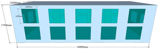
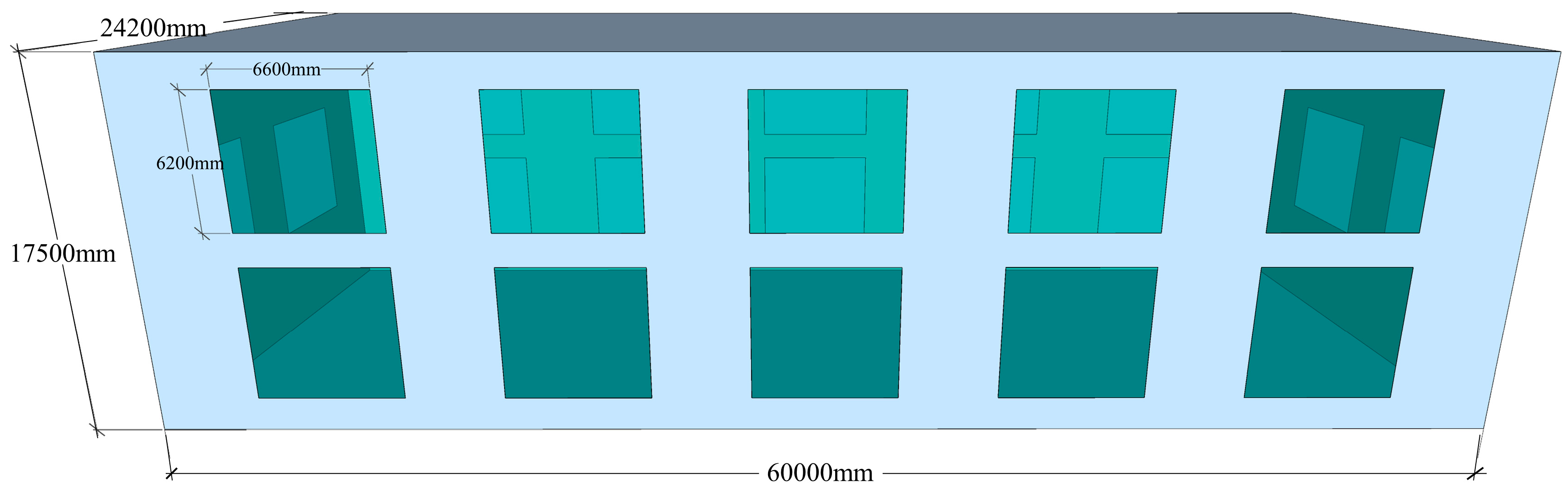
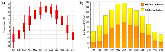
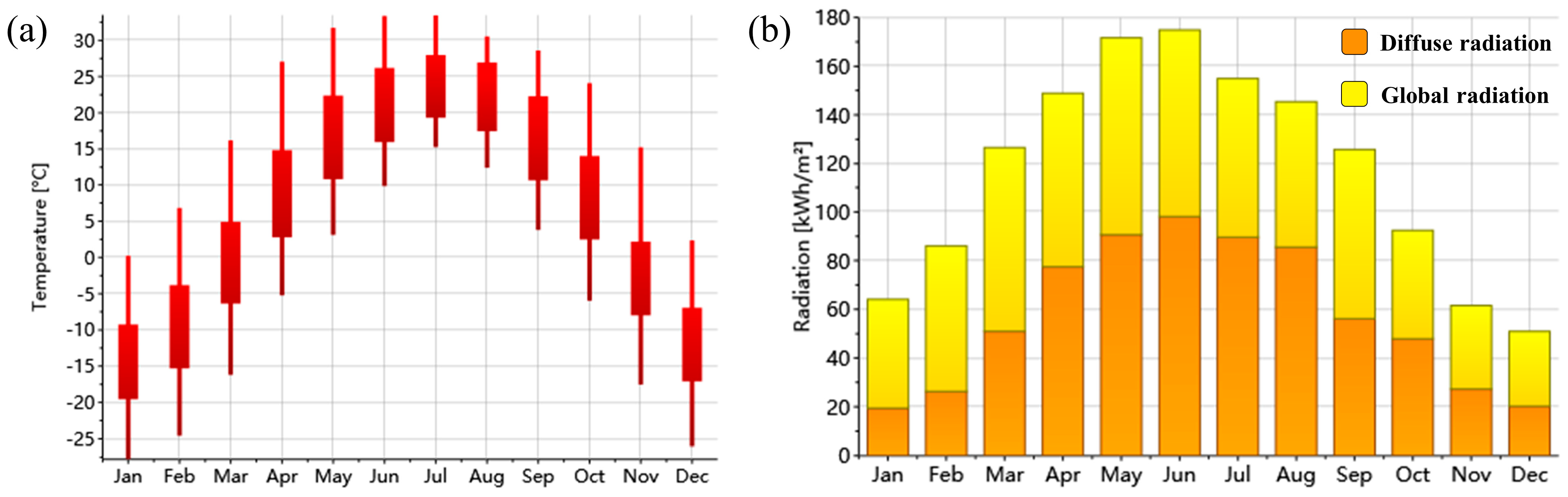
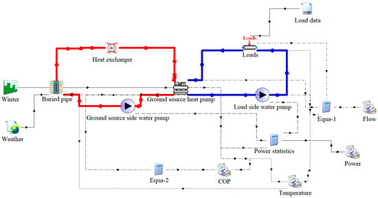
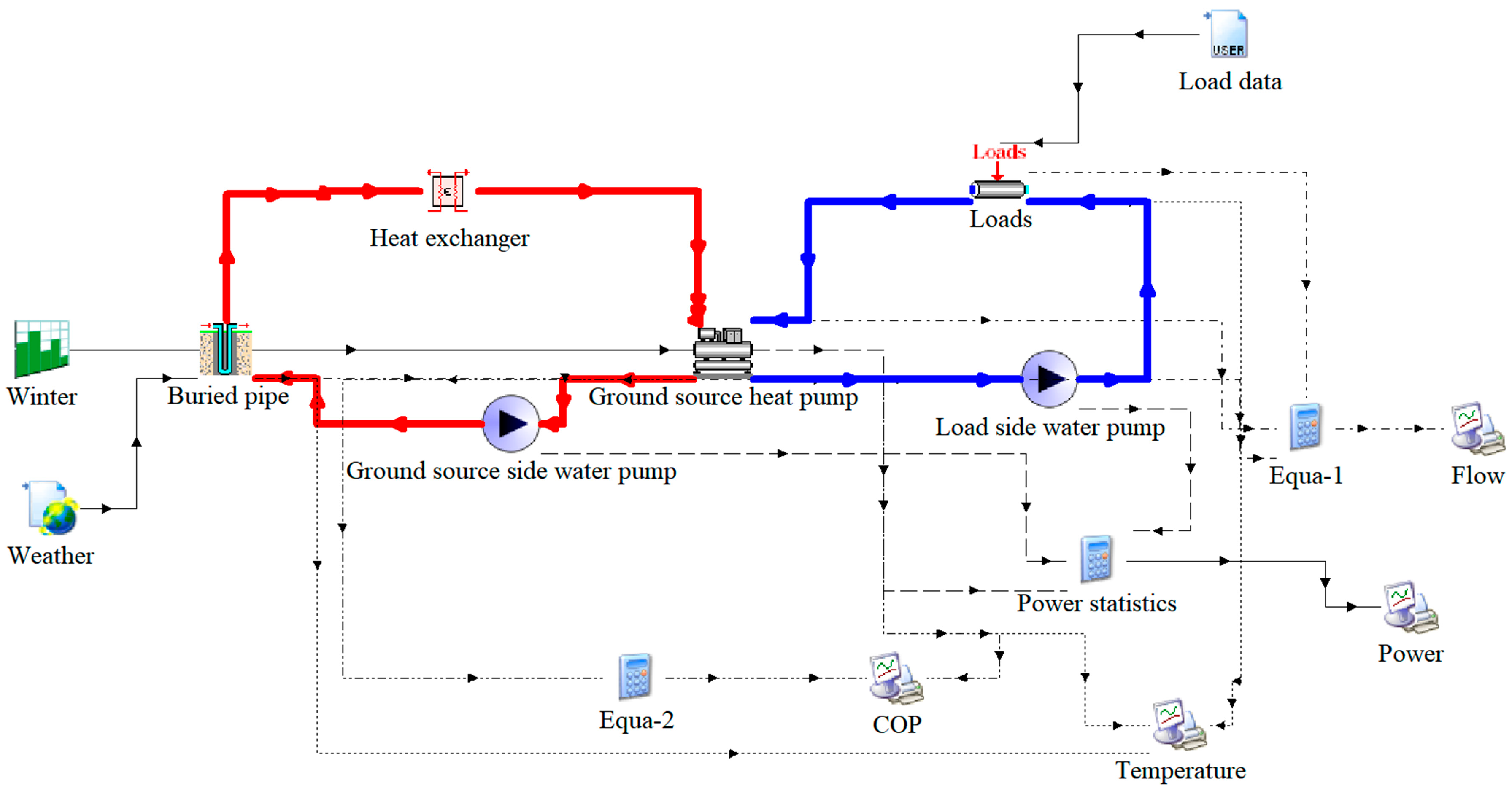
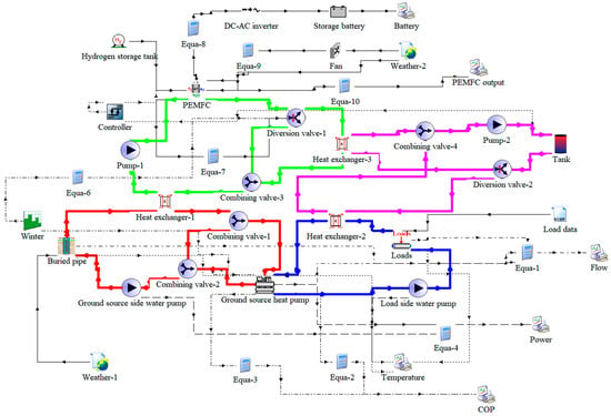
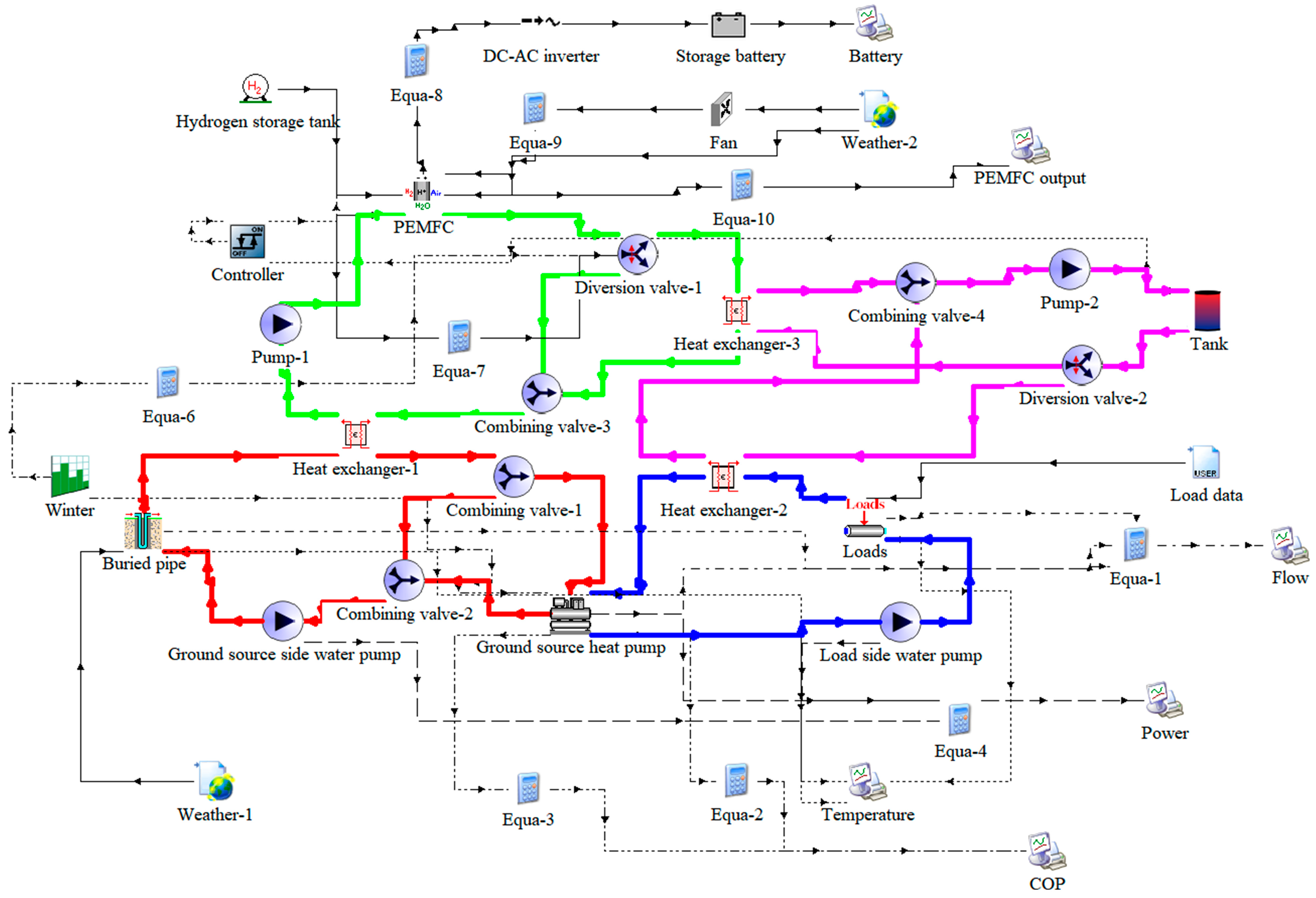
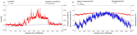
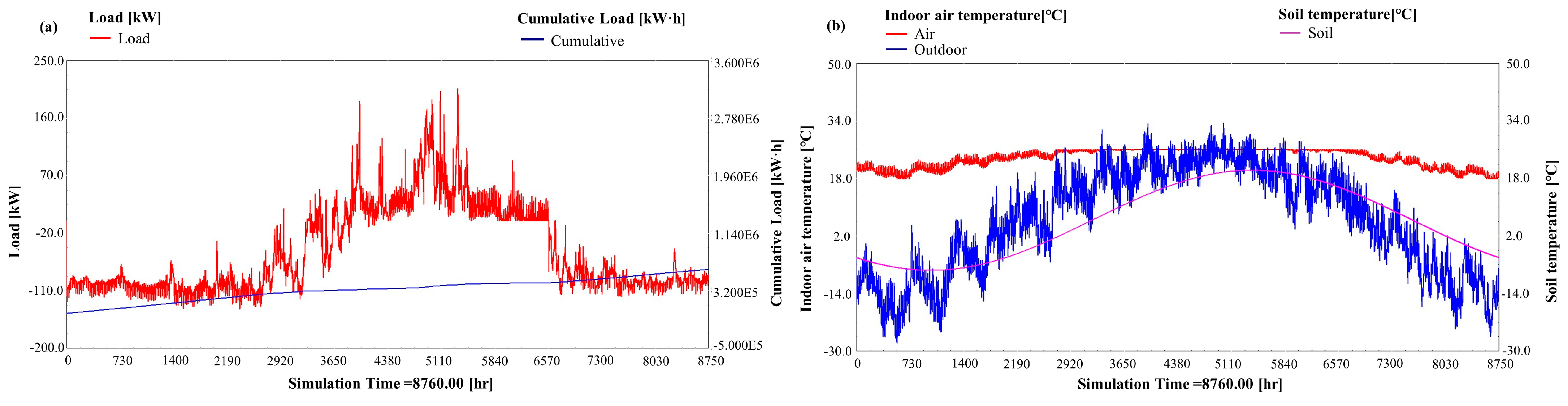
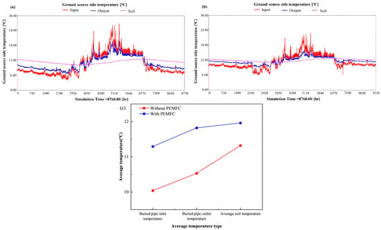
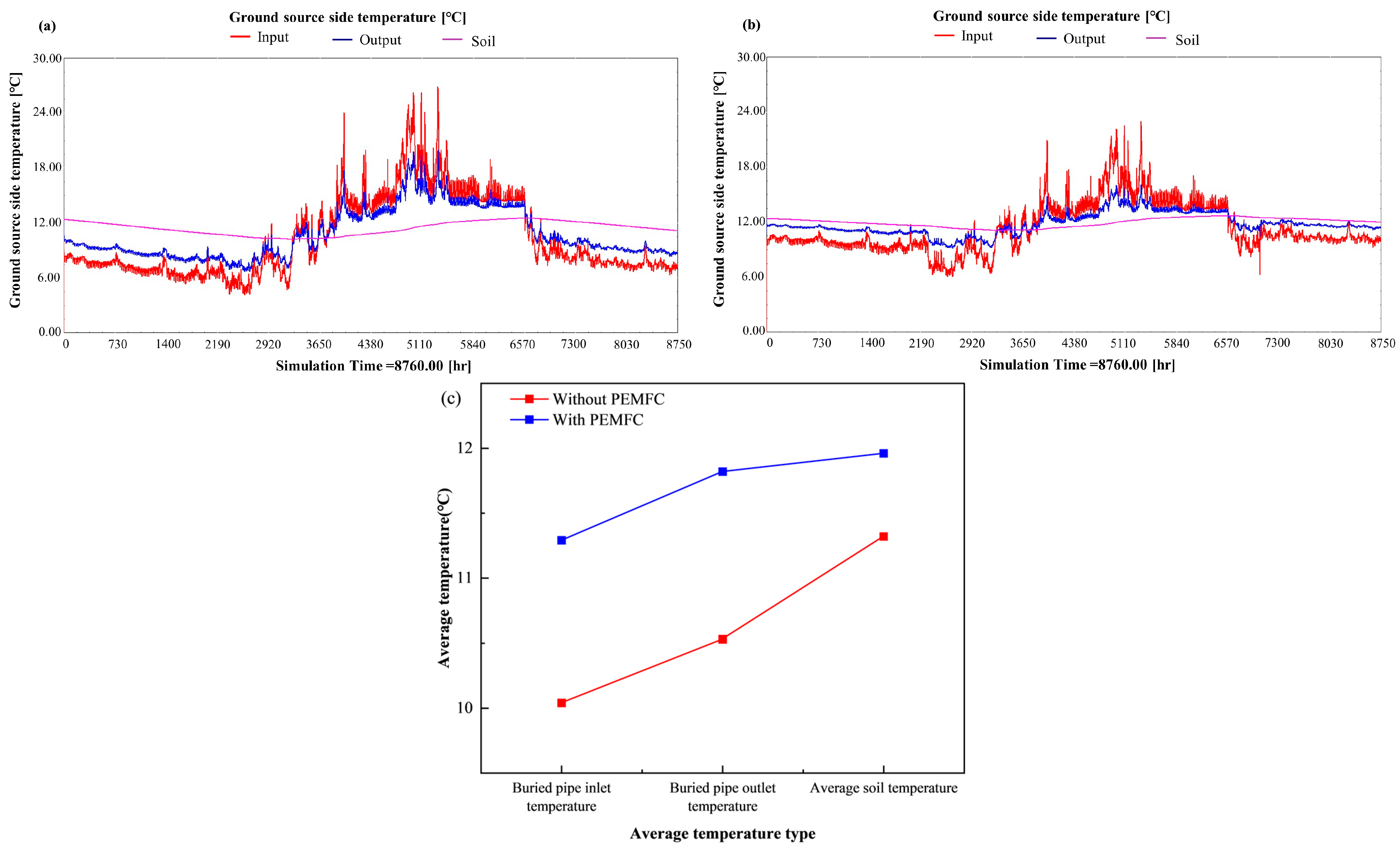
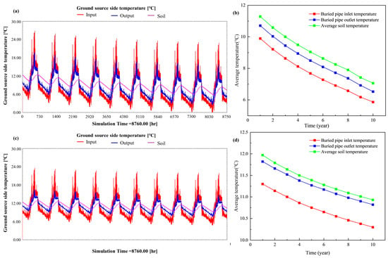
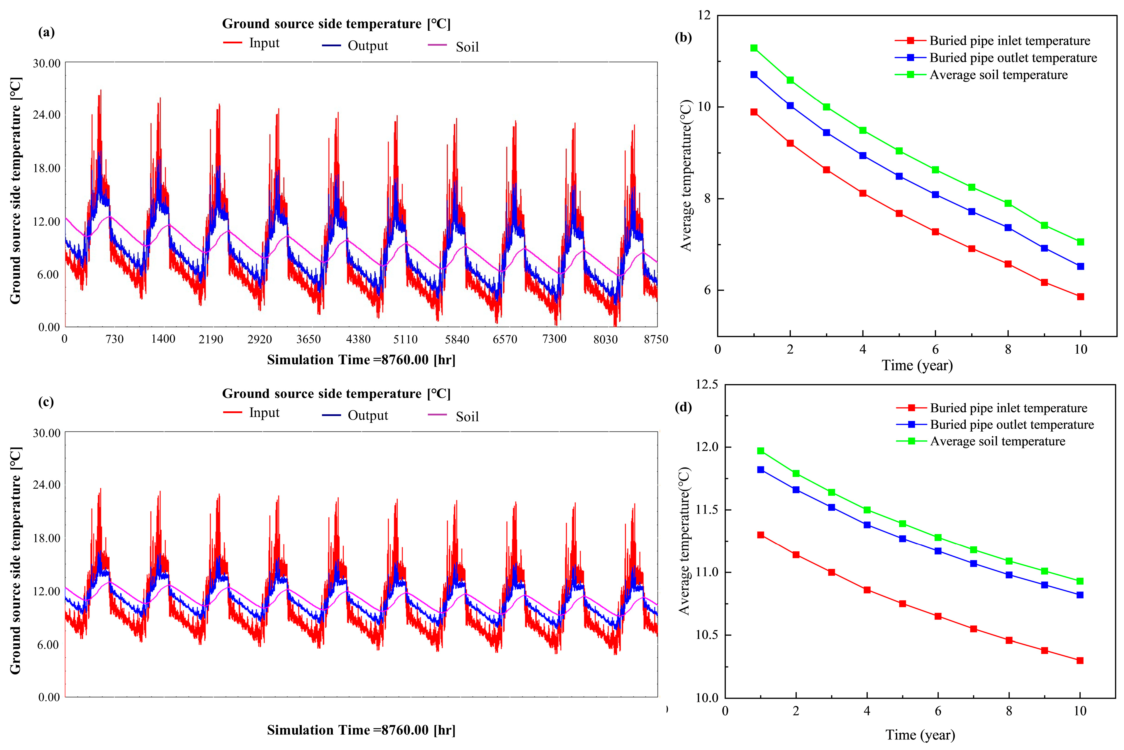
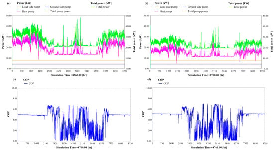
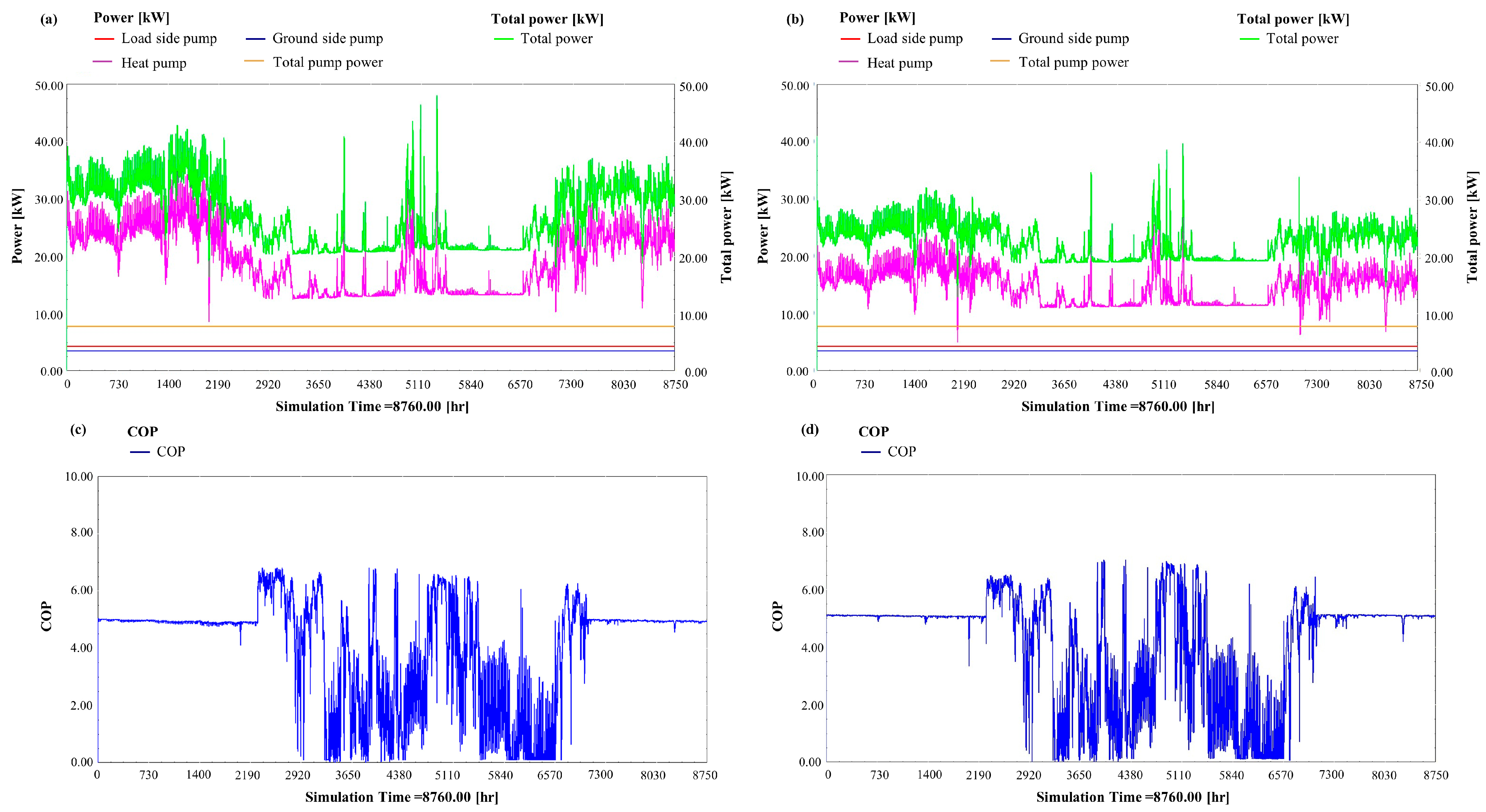
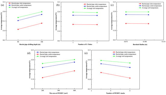
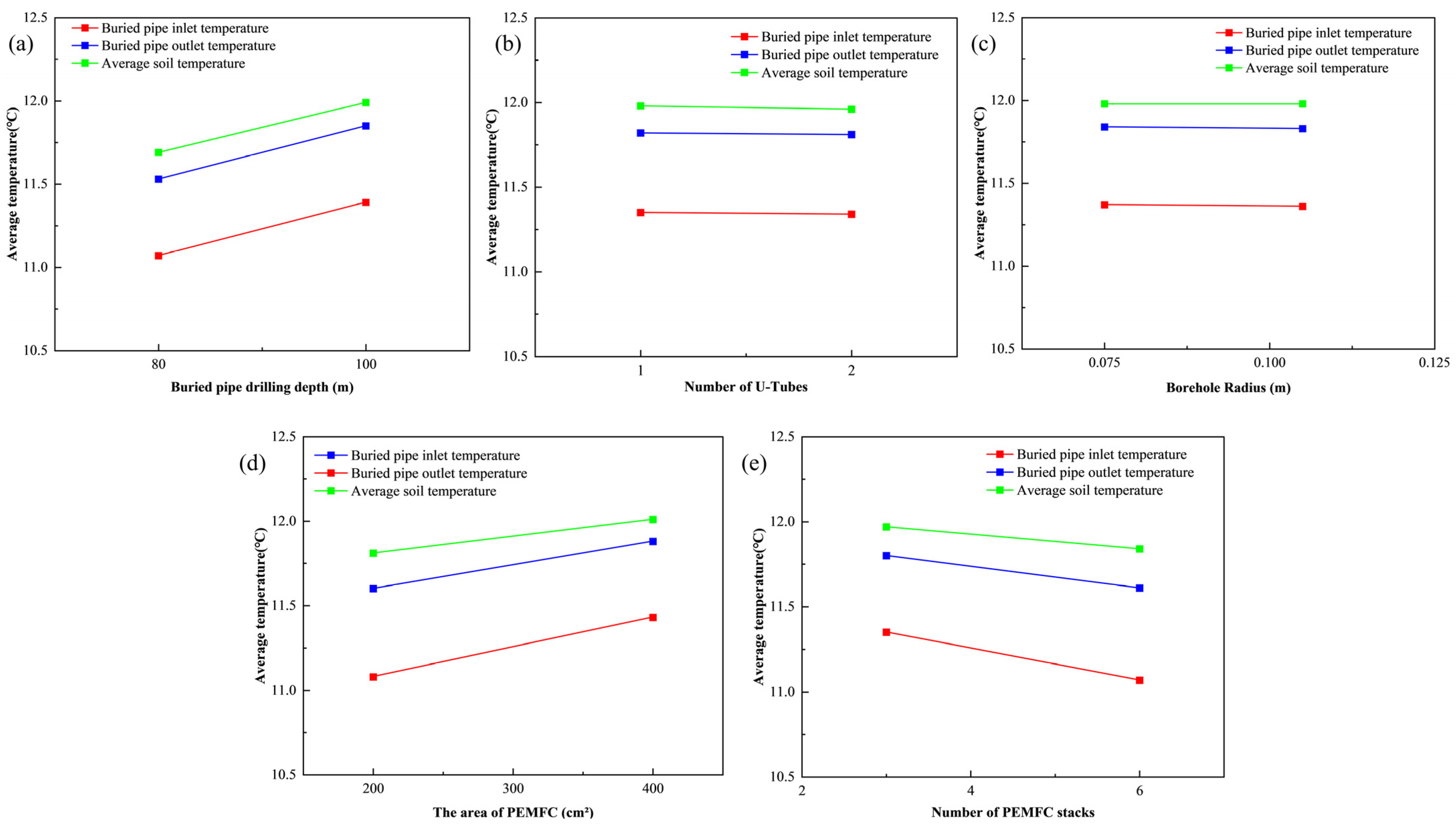

Disclaimer/Publisher’s Note: The statements, opinions and data contained in all publications are solely those of the individual author(s) and contributor(s) and not of MDPI and/or the editor(s). MDPI and/or the editor(s) disclaim responsibility for any injury to people or property resulting from any ideas, methods, instructions or products referred to in the content. |
© 2026 by the authors. Licensee MDPI, Basel, Switzerland. This article is an open access article distributed under the terms and conditions of the Creative Commons Attribution (CC BY) license.