


Abstract
The SP Gas Storage is situated in the SP-Xingcheng structural belt, where volcanic gas reservoirs are widely distributed and characterized by abundant primary microfractures and pore structures. The developed pores and fractures degrade the petrophysical properties of reservoirs and render volcanic basement rocks highly abrasive. In addition, pore-fracture systems alter the internal stress field of formations, which substantially increases the risk of wellbore instability and the collapse of injection and production wells. This poses great challenges to drilling operations and the safe running of the gas storage in this block. To systematically clarify the wellbore instability mechanism of large-diameter wellbores and address the drilling engineering problems in the study area, a dedicated experimental scheme for large-diameter wellbore stability was designed in this work. Laboratory true triaxial tests were conducted on wellbore stability with different borehole sizes, and basic mechanical parameter tests of reservoir rocks were also completed. This study systematically investigates the evolution of rock mechanical parameters and the surrounding stress-reconstruction mechanism induced by pore-forming unloading and identifies the dominant internal mechanism of wellbore instability under large-diameter conditions. A clear distinction is made between the formation stress redistribution caused by stratum exposure and unloading during drilling and formation stress evolution during the subsequent injection and production of the gas storage. On this basis, the fracture initiation threshold, propagation paths, and morphological evolution in thin interbedded sandstone–mudstone reservoirs are further analyzed. Combined with rock mechanical parameters and in situ stress balance conditions, criteria and quantitative evaluation methods for wellbore instability discrimination are finally established.
1. Introduction
The Northeast region is a key area rich in oil and gas resources in China, and the SP block is a core unit for oil and gas production capacity construction in the Northeast. Affected by the long-term evolution of regional geological structures, the Yicheng Formation in the upper part of the SP block has a typical interbedded sandstone and mudstone structure, with widespread micro-fractures, complex orientations, and an uneven distribution. In some areas, fractures are interconnected, causing damage to the integrity of the formation. During drilling in this layer, wellbore instability occurs frequently, manifested as collapse, rock fall, and wellbore constriction, which not only reduces drilling efficiency, delays progress, and increases costs, but also may lead to a stuck pipe and lost pipe and other safety accidents, seriously restricting the advancement of gas-storage well-drilling projects. Existing studies have shown that the risk of wellbore instability in fractured formations is much higher than that in intact formations. Fractures weaken the rock strength and provide channels for drilling fluid invasion. At the same time, the sandstone and mudstone in this area have low mineral hardness, poor cementation, and insufficient shear strength and are prone to deformation and shedding under drilling disturbances and in situ stress, jointly inducing wellbore instability.
At present, scholars at home and abroad have conducted multi-dimensional research on the problem of wellbore instability in such fractured sandstone and mudstone formations [1,2,3,4,5]. It has been clearly established that high-brittleness mineral components and high-permeability fracture networks are the core internal factors causing wellbore collapse. The development of fractures can cause pore pressure fluctuations, stress concentration around the wellbore, and the deterioration of wellbore strength. Existing prevention and control technologies mainly focus on drilling fluid optimization, the adjustment of construction parameters, and conventional plugging and support. Although they are effective in some well sections, research on the complex stress reconstruction and fracture propagation mechanism of large-diameter wellbores is still relatively weak, making it difficult to completely solve the problem of wellbore stability.
Scholars at home and abroad have conducted systematic research in relevant fields for decades and established a comprehensive theoretical system covering rock brittle damage, multi-field coupling [6], which lays a foundation for the stability analysis of wellbores in complex formations [7,8,9,10,11]. A complete research framework has been formed for wellbore stability mechanics, and leading researchers have clarified the fundamental mechanical inducements of wellbore instability [12,13,14]. Nevertheless, traditional theories are poorly applicable to deep formations under high in situ stress, and test results from small-sized core samples fail to truly reflect the mechanical responses of large-scale surrounding rock in field conditions. Therefore, it is urgent to improve the relevant test systems and evaluation models [15,16].
Wellbore instability in formations with developed natural fractures is a worldwide challenge. The academic community generally recognizes that natural fracture networks alter the seepage field and accelerate pore pressure propagation, while existing evaluation models show limited applicability under high-stress unloading [17,18]. The superposition of thermally induced stress and seepage stress caused by fracture flow conduction aggravates surrounding rock failure [19]. Dynamic unloading during drilling leads to the expansion of micro-fractures and the deterioration of mechanical parameters of rock masses [20,21,22]. Research on drilling fluid invasion further enriches the multi-factor coupling theory of wellbore instability [23,24,25]. The brittleness and lithological heterogeneity of interbedded sand-mud formations are inherent factors triggering wellbore instability [26,27]. Interlayer interfaces are prone to delamination and slip under stress disturbance, and the properties of hard brittle formations further exacerbate damage induced by drilling disturbances. The mechanical responses of large-diameter wellbores for gas-storage reservoirs differ from those of conventional drilling wells, and relevant research remains insufficient. Although China has made progress in drilling and completion technologies for gas-storage reservoirs, there is still a gap compared with advanced international technologies [28]. Issues including the wellbore stability of large-diameter boreholes remain common technical bottlenecks in the industry [29,30]. Field practices also demonstrate that the construction of large-diameter boreholes faces numerous potential safety hazards.
Previous scholars have investigated the wellbore stability characteristics of fractured formations via diverse research approaches and put forward corresponding technical suggestions [31,32]. Distinct from conventional research objects, wellbores at the SP Gas Storage are generally designed with large diameters, while traditional calculation models ignore the size effect on formation pressure, resulting in prominent calculation errors. Conventional experimental research mainly focuses on formation damage induced by drilling fluid fracturing, yet few studies concentrate on the influence of the borehole diameter on wellbore stability, leading to insufficient studies targeting large-diameter wellbore mechanical analyses.
To fill such research gaps, based on indoor rock mechanics experiments, the author’s team proposes improvements against the deficiencies of existing theories. Relying on the geological features of the target block, this paper systematically carries out research on large-diameter wellbore stability and designs a dedicated test scheme to implement true triaxial tests under various borehole sizes. A coupled stress-seepage mechanical model is established to reveal the dynamic propagation and evolution mechanism of natural fractures around large-diameter boreholes and quantitatively characterize the regulation law of interlayer modification based on wellbore stability. The obtained conclusions can provide a solid theoretical reference and technical support for the safe drilling and efficient reservoir stimulation of large-diameter wells in the SP Gas Storage.
2. Comprehensive Logging and Geological Evaluation of SP Gas Storage
The SP area is mainly characterized by interbedded sandstone and mudstone strata. The upper Yingcheng Formation contains a small amount of rhyolite with grayish–yellow and purplish–red weathered surfaces. The lower Quantou Formation and Denglouku Formation are dominated by unequal-thickness interbeds of brownish–tan and purplish–red mudstone, as well as purple–gray and grayish–white sandstone.
The strata in this area are loose with poor cementation and inferior reservoir physical properties. The average porosity is 8.4%, ranging from 4.0% to 27.5%, and the average permeability is 1.19 mD, with a range of 0.006–319 mD, mostly concentrated between 0.01 and 1 mD.
As shown in Figure 1, the Denglouku Formation was deposited during the tectonic transition stage when basin faulting ceased and the depression basin initially developed. It is predominantly composed of fluvial sediments and widely distributed regionally. Its thickness and distribution are significantly controlled by basement faults with strong lateral heterogeneity, and the Member 1 of the Denglouku Formation is absent within the study well area.
Figure 1.
Measured geological section of Denglouku Formation.
The sedimentary environments of the second and third members of the Denglouku Formation were unstable, resulting in poor sedimentary stability, highly variable stratigraphic thickness, and an irregular spatial distribution. The lithology is mainly represented by unequal-thickness interbeds of dark purplish–red, dark purple, and grayish–purple mudstones, as well as gray siltstones and fine sandstones. The lower part of the second member develops interbeds of dark purple mudstone and gray glutenite. In contrast, the sedimentary framework of the fourth member remained relatively stable, with the stratigraphic thickness gradually increasing from west to east, and its lithology consists mainly of unequal-thickness interbeds of dark purple mudstone, silty mudstone, gray siltstone, and argillaceous siltstone.
Tectonically, the Xuxi Fault had ceased activity during the deposition of the Denglouku Formation. Fault development in the study area is weak, dominated by NNW-trending faults, together with NNE-trending and nearly NS-trending faults. A total of 439 faults are identified in the three members of the Denglouku Formation, including 86 faults with an extension length greater than 1.5 km and 353 faults less than 1.5 km. Within the gas storage area, nine mainly NNW-trending faults are developed, among which three faults feature deep cutting and extend from the Yingcheng Formation to the top surface of the second member of the Denglouku Formation.
3. Laboratory Tests on Rocks in Sand–Mud Interbedded Strata
3.1. XRD Mineral Composition Test
As shown in Figure 2, the cuttings for X-ray diffraction (XRD) mineral composition tests were collected from downhole samples of the SP Gas Storage and ground into powder. All specimens were kept dry and isolated from air, with the particle size controlled at 320 mesh (approximately 40 μm). The rock cuttings were ground and sieved using mortars, pestles, and standard sieves, and particles were repeatedly screened to achieve a fine grain size during the process. The particle size was considered qualified when no granular texture could be felt by touch. Afterwards, the powder samples were made into whole-rock slices for subsequent testing.
Figure 2.
Downhole cuttings and ground powder.
Based on the mineral composition test data of sandstone and mudstone of the Denglouku Formation in the SP Gas Storage listed in Table 1, a systematic analysis can be conducted on the mineralogical characteristics, diagenetic evolution background, and engineering geological significance of lithologies in different intervals of the Denglouku Formation. Overall, significant differences in mineral composition exist between the sandstone of Member 1 and the mudstone of Member 2 of the Denglouku Formation, reflecting varied sedimentary environments, diagenetic evolution pathways, and reservoir-cap rock assemblage characteristics. These findings provide critical mineralogical evidence for understanding the controlling factors of reservoir quality and wellbore stability in the SP Gas Storage.
Table 1.
Mineral composition contents of sandstones and mudstone in SP Gas Storage.
In terms of the mineral composition of sandstone samples from Member 1, the framework minerals are dominated by quartz and plagioclase. The quartz content ranges from 34.9% to 39.5%, and the plagioclase content is between 19.4% and 20.8%. The total proportion of the two minerals exceeds 55%, forming a rigid supporting framework that determines the overall strength and compaction resistance of the reservoir. Meanwhile, the sandstone contains a relatively high content of clay minerals, ranging from 28.8% to 32.9%. These clay minerals mostly occur in the forms of pore fillings, grain coatings, or matrix materials. They not only block pore throats and reduce reservoir permeability but also induce water sensitivity, velocity sensitivity, and salt sensitivity when contacting external fluids during drilling, injection, and production operations. Such interactions lead to the hydration expansion, dispersion, and migration of clay minerals, weaken the cementation strength between rock particles, and become a key hidden danger affecting wellbore stability. In addition, the sandstone contains 6.9% to 7.2% calcite cement, with locally distributed barite ranging from 4.0% to 5.9%, indicating differential fluid activities during diagenesis. Calcite cement enhances the compaction resistance and mechanical strength of partial sandstone, while the intermittent distribution of barite reflects variations in the salinity of diagenetic fluids or precipitation of local pore fluids. This results in heterogeneous cementation, strengthens the spatial heterogeneity of rock mechanical properties, and creates potential weak planes for subsequent wellbore instability. In general, the sandstone of Member 1 is characterized by a high clay content, a moderate quartz–feldspar content, and localized carbonate cementation. It is typical lithic feldspathic sandstone with a medium to high clay content. This type of rock is highly susceptible to hydration during drilling, accompanied by obvious strength degradation and high risks of wellbore instability.
Distinct mineralogical differences are observed in the mudstone of Member 2 compared with the sandstone of Member 1. No clay minerals are detected in the mudstone samples. Quartz and feldspar constitute the primary framework minerals, with the quartz content reaching 45.3–49.1% and the total content of K-feldspar and plagioclase ranging from 29.2% to 33.7%. The total proportion of brittle minerals exceeds 75%, resulting in high rock brittleness and high susceptibility to shear failure and fracture propagation under external stress. Furthermore, the mudstone contains 5.2–5.8% calcite, 6.6–7.5% dolomite, and 4.5–4.9% anhydrite, forming a composite carbonate–sulfate cementation system. Although these cements improve the compaction resistance of mudstone to a certain extent, they also form weak zones vulnerable to fluid dissolution and alteration. Calcite and dolomite are easily dissolved by acidic fluids, while anhydrite may experience hydration expansion in freshwater environments. Both processes reduce the local cementation strength and induce the initiation and expansion of microfractures. Additionally, the mudstone contains 4.0–4.3% siderite. As iron-bearing carbonate minerals, siderite is susceptible to oxidation and dissolution in the late diagenetic stage, further aggravating the heterogeneity of rock mechanical properties. Overall, the mudstone of Member 2 is characterized by high brittle mineral content, low clay mineral content, and widespread carbonate–sulfate cements. With poor plasticity and strong brittleness, this mudstone is prone to brittle fracturing under wellbore stress disturbances and fluid interaction, resulting in wellbore spalling and block falling and posing a serious threat to wellbore integrity.
From the perspective of engineering geology and gas storage development, the above mineral-composition characteristics possess important guiding significance. The high clay content of Member 1 sandstone requires the adoption of a low-damage and low-water-sensitivity drilling fluid system during drilling to inhibit clay hydration and expansion and mitigate rock strength attenuation. In contrast, the high brittleness and carbonate cementation of Member 2 mudstone demand reasonable control of wellbore stress disturbance in drilling practices, so as to avoid brittle fracturing induced by improper drilling fluid density and wellbore size effect. Meanwhile, fluid properties during injection and production should be optimized to reduce the dissolution risk of carbonate cements and prevent cap rock damage during reservoir stimulation. Moreover, the mineralogical heterogeneity between sandstone and mudstone of the Denglouku Formation requires full consideration of the spatial variation of rock mechanical parameters in wellbore stability analysis. Establishing mechanical models consistent with actual geological conditions based on mineral-composition characteristics can provide technical support for the safe and efficient development of the SP Gas Storage.
3.2. Cold Field Emission Scanning Electron Microscope
Long-term immersion in drilling fluid significantly degrades the mechanical properties of sandstone, which is jointly controlled by the fluid–rock interactions and rock anisotropy. Before immersion, sandstone is characterized by developed pores and microcracks, dense particle cementation, and a stable structure. During immersion, water molecules in the drilling fluid induce the hydration and expansion of clay minerals, weaken the cementation strength, and accompany the dissolution and recrystallization of salt minerals, thereby altering the pore structure. The original fractures and weakly cemented zones of rock suffer preferential damage and promote the initiation and propagation of new cracks. Meanwhile, the damage degree varies obviously in different directions, which fully reflects the anisotropy of sandstone in structural characteristics and mechanical response.
The Figure 3 presents scanning electron microscopy (SEM) images of sandstone samples collected from the Denglouku Formation in the SP Gas Storage at a magnification of 672 times. The samples contain abundant clay minerals, which occur as scaly and fibrous aggregates extensively filling intergranular pores and grain margins, with continuous clay bridge structures developed in local zones. Most clay minerals coat the surfaces of quartz and feldspar grains in the form of thin films or fill intergranular spaces as flocculent and aggregated masses, which markedly reduce the primary porosity of rock and may cause plugging of pore throats.
Figure 3.
SEM scanning of sandstone particle structure before immersion.
The extensive development of clay minerals not only intensifies reservoir heterogeneity, but also provides material conditions for hydration expansion, dispersion, and migration after drilling fluid invasion. It serves as one of the critical factors that enhance reservoir water sensitivity and degrade rock mechanical strength. The morphology and distribution characteristics of clay minerals in the images directly verify the high clay mineral content of the First Member sandstone concluded from the previous X-ray diffraction (XRD) analysis and offer direct microscale evidence for wellbore stability analysis and the reservoir-protection design of this reservoir.
The evolution of these microstructures directly degrades the macroscopic mechanical properties of sandstone, manifested as a reduced elastic modulus and compressive strength. With the extension of soaking time, hydration damage accumulates gradually, and the attenuation of mechanical properties increases rapidly at first and then slows down, which conforms to the general law of the characteristic hydration time. Long-term fluid–rock interactions also significantly affect mesoscopic structural parameters. Indicators such as the equivalent pore radius, pore volume, and pore quantity change regularly with the soaking process, thereby driving the expansion of damage from local regions to the overall rock mass.
In the Figure 4, rigid framework grains such as quartz and feldspar are generally developed with transgranular cracks and intergranular microfractures. Some grains are cut into fragmented blocks by fractures with disordered extension directions, forming a complex microfracture network. These fractures are irregularly distributed among mineral grains and penetrate multiple mineral particles. Obvious stress fragmentation traces can be observed at the edges of partial fractures, indicating that the reservoir has undergone intense tectonic stress transformation.
Figure 4.
SEM scanning of sandstone particle structure before soaking.
The development of abundant microfractures significantly reduces the overall rock strength and provides preferential channels for fluid invasion, which further aggravates hydration damage and instability risks. It acts as a vital micro-controlling factor for the frequent occurrence of brittle fractures, spalling, and block collapse of the wellbore in this reservoir. Therefore, when evaluating the wellbore stability of sandstone formations, it is necessary to focus not only on the variations of conventional physical and mechanical parameters, but also systematically analyze the influence of fracture propagation on overall wellbore failure combined with mesoscopic structure characterization methods.
3.3. Test of Rock Porosity, Permeability, and Mechanical Parameters
3.3.1. Principle of Gas Permeability Measurement
As shown in Figure 5, this experiment was carried out in accordance with Darcy’s law. Using nitrogen as the testing medium, a pressure difference was applied across both ends of the core sample, and core permeability was calculated by monitoring the inlet and outlet pressures, as well as the outlet flow rate. The specific procedures are as follows: the core samples were first dried to a constant weight and placed into a core holder, with the confining pressure set at 3 MPa. The gas cylinder was opened and the pressure reducing valve was adjusted. After the inlet pressure and outlet flow became stable, the gas permeability was measured. Subsequently, the inlet pressure was slightly adjusted, and two additional groups of permeability tests were repeated once the flow stabilized, with the average value adopted. Upon completion of the test, the gas supply was shut off, the confining pressure was released, and the core sample was removed.
where: Kg—Gas permeability of the rock, 10−3 μm2;
Figure 5.
Combined porosity and permeability tester under confining pressure.
μ—Fluid viscosity under test conditions, mPa·s;
L—Core sample length, cm;
A—Cross-sectional area of the core sample, cm2;
Pa—Standard atmospheric pressure under test conditions, MPa;
Q0—Gas volume flow rate through the core sample over a given period, cm3/s;
P1—Inlet pressure of the core sample, MPa;
P2—Outlet pressure of the core sample, MPa.
3.3.2. Analysis of Porosity and Permeability Test Results
As shown in Table 2 and Table 3, the experimental samples are divided into two categories: sandstone and mudstone of the Denglouku Formation. According to the classification criteria for porosity and permeability of mudstones, the Denglouku Formation mudstone is characterized by low porosity and medium–low permeability. The porosity shows little variation between wells, ranging from 2% to 4%, while the permeability varies significantly, ranging from 5 × 10⁻³ μm2 to 20 × 10−3 μm2. As a whole, the formation is prone to filtrate loss when interacting with drilling fluids.
Table 2.
Porosity and permeability tests of mudstone.
Table 3.
Sandstone porosity and permeability tests.
In contrast, according to the classification criteria for the porosity and permeability of sandstones, the Denglouku Formation sandstone is characterized by low–medium porosity and medium–high permeability. The porosity shows little inter-well variation, ranging from 11% to 12%, while the permeability varies significantly, ranging from 12 × 10−3 μm2 to 66 × 10−3 μm2.
3.3.3. Rock Mechanical Parameters
Rock mechanical parameters characterize the mechanical properties of rock materials and play a vital role in rock engineering, geological engineering, seismology, and other disciplines. In oil and gas well drilling operations, complete core sampling for all formation intervals is usually impractical, whereas rock mechanical parameters are essential for borehole stability analysis. Therefore, as shown in Table 4, an empirical method based on well logging data is established in this study to predict the above parameters. Dynamic rock mechanical parameters can be calculated using the compressional acoustic transit time, bulk density, and natural gamma-ray (GR) logging data in combination with the equilibrium, geometric, and constitutive equations of elastic mechanics.
Table 4.
Sandstone porosity and permeability tests.
An empirical conversion formula between compressional wave velocity and its acoustic transit time is expressed as follows:
where ∆t denotes the compressional acoustic transit time, in s/m.
To reduce field logging costs, only compressional wave acoustic logging is commonly implemented on-site. For sand–shale formations, an empirical correlation between compressional and shear wave velocities dependent on the rock density is determined via the laboratory ultrasonic testing of field core samples:
where is the bulk density, in .
Assuming homogeneous isotropic formations, dynamic Poisson’s ratio and the dynamic elastic modulus can be calculated from compressional wave velocity, shear wave velocity, and bulk density:
where dynamic Poisson’s ratio; = dynamic elastic modulus, unit: .
Subject to the in situ formation stress state, loading rate and rock deformation characteristics of the subsurface strata, static rock mechanical parameters obtained from triaxial compression tests better reflect actual rock mechanical behaviors. Affected by pore fluids, dynamic parameters fail to represent the intrinsic mechanical properties of in situ rocks; hence, static parameters are required for in situ stress computation and practical engineering design. It is therefore necessary to establish a dynamic-to-static conversion model to acquire static mechanical parameters via regression analysis between measured core mechanical data and conventional logging data:
where = static Poisson’s ratio; = static elastic m. Based on abundant laboratory experiments, Deere and Miller proposed an empirical relation between the uniaxial compressive strength and shale content for sedimentary rocks. Experimental results also indicate that the rock tensile strength accounts for 1/8–1/12 of its uniaxial compressive strength: modulus, unit: .
where = uniaxial compressive strength; tensile strength, unit: MPa; Vd clay volume fraction.
Coates put forward an empirical formula for cohesion calculation from experimental research:
where c = cohesion, MPa; Kd = dynamic shear modulus, MPa.
The rock type, grain size, and other factors affect internal friction angle, which is generally quantified by regression of experimental data:
where = internal friction angle, ; , , are rock-specific empirical constants.
4. Large-Scale Physical Model Test of Wellbore Stability
4.1. Large-Scale True Triaxial Wellbore Stability Experiment
In general, the borehole size exerts a size effect by altering the stress concentration around the wellbore and the propagation law of the plastic zone in surrounding rock. As the borehole diameter increases, the formation unloading range induced by well excavation expands, aggravating stress concentration near the borehole wall. Consequently, the surrounding rock fails to form a stable load-bearing stress arch, and the plastic failure zone continuously extends deep into the formation. For mud shale and fractured clastic formations, the creep deformation of surrounding rock and hydration triggered by invasive drilling fluid are intensified, raising the collapse pressure and reducing fracture pressure of the formation, narrowing the safe density window of the drilling fluid and synchronously increasing risks of borehole collapse and lost circulation. When the borehole size decreases, the self-supporting arch effect of the surrounding rock is remarkably strengthened and the development of the plastic zone is restrained, which is mechanically favorable for borehole stability. Nevertheless, the reduced annular cross-section increases the flow velocity of the drilling fluid, and high-speed fluid scours the borehole wall, easily triggering local erosional collapse in unconsolidated sandstone intervals. For intact tight hard formations, the borehole size has a negligible regulating effect on wellbore stability.
Wellbore stability refers to the condition where the actual drilling fluid density falls within the safe range bounded by the critical collapse density and critical fracture density. Under such circumstances, hydrostatic pressure can effectively counterbalance in situ stress and restrain the shear failure and tensile cracking of rocks around the wellbore, resulting in a regular wellbore geometry without obvious downhole hazards such as cuttings falling, hole shrinkage, lost circulation, or formation influx during drilling and tripping operations. In contrast, wellbore instability mainly includes shear collapse and hydraulic fracturing. If the drilling fluid density is lower than the critical collapse density, shear failure occurs in the surrounding rock, characterized by hole enlargement from rock sloughing and pipe sticking; if the drilling fluid density exceeds the critical fracture density, tensile fractures initiate on the borehole wall and the drilling fluid invades formation pores and fractures to cause lost circulation. Both aforementioned conditions are defined as wellbore instability.
To reveal the instability mechanism of large-diameter boreholes under varying well sizes, physical simulation experiments on the wellbore stability of sandstone–mudstone interbedded strata were performed under in situ stress by using a true-triaxial physical simulation system. Seven outcrop blocks of the Denglouku Formation were collected from the Shengping Block, 500 m to the west of Zhuanshanhu Dam in Yehe Town, Siping City. The outcrop fault zone is approximately 150 m long and 5–45 m high, with its measured geological profile shown in the corresponding figure. This structural profile consists of conglomerate, mudstone, pebbly sandstone, silty mudstone, and fine sandstone, accompanied by structural lenticles, lithology-bound joints, and flower structures. Affected by regional tectonic compression, different lithologies are squeezed together, featured by abundant lenticular bodies and well-developed flower structures.
All collected rock blocks were cut by a specialized rock cutter into uniform specimens with dimensions of 280 mm × 280 mm × 280 mm for subsequent sample assembly and laboratory testing. A rock sample mold with a dimension of 290 mm × 290 mm × 290 mm was preassembled. As shown in Figure 6, the processed outcrop sample is precisely placed at the center of the mold. Uniform gaps are reserved around the sample and the inner wall of the mold to provide sufficient space for full cementation between the cement slurry and the outcrop sample.
Figure 6.
Placement diagram of cut outcrop sample and mold.
The cement slurry was prepared by mixing quartz sand and cement at a mass ratio of 1:1 with water to form a homogeneous and viscous mixture. The slurry was slowly injected into the mold to fully wrap the outcrop sample without omission or voids. After injection, the mold was kept stationary for no less than 48 h to ensure sufficient cementation and solidification between the cement and the rock sample.
Figure 7 shows the effect after the cement and outcrop sample solidify. After the cement slurry is fully cemented and hardened with the outcrop sample, the mold is disassembled and the molded rock block is taken out. Sandpaper and an angle grinder were used to finely polish the edges, corners, and irregular parts formed by cement solidification. Medium and large holes and cracks with insufficient cementation on the block surface were filled and repaired with a special cementing adhesive. After the adhesive was fully cured, secondary polishing was conducted again with sandpaper and the angle grinder. This ensured that all six end faces of the rock block were smooth and flat, with a length, width, and height no more than 295 mm.
Figure 7.
Static placement diagram of the mold after cement slurry injection.
Using a large-size drilling rig, boreholes with diameters of 5 cm, 6 cm, 7 cm, 8 cm, and 10 cm were drilled on the outcrop side of each rock block, with a uniform drilling depth of 20 cm for all holes.
As shown in Figure 8, a through hole with a diameter of 2 cm was drilled on the opposite side of the large-size borehole to realize precise alignment of the two holes and form an integrated flow channel. A base plate whose area was no less than that of a single face of the rock block was prepared. Sufficient special bonding adhesive was evenly smeared on the central region of the base plate, and the coated area was larger than the aperture of the large borehole. The rock block was stably placed upside down with the large-diameter opening facing downward, allowing the adhesive to fully cover the wellhead of the large-size borehole. Afterwards, uniform downward pressure was applied to the rock block to achieve tight adhesion between the adhesive and cement surface.
Figure 8.
Rock specimen after drilling using large-size drilling rig.
Afterwards, edible salt was evenly poured into the 2 cm-diameter upper hole until the stacking height was 4 cm below the orifice. The special cementing adhesive was then filled into the hole. The bottom of the wellbore was sealed with adhesive tape, and the wellbore was slowly rotated and installed into the channel. Weights were placed on the top for compaction and fixation. The rock sample was kept stationary for no less than 24 h for curing, so as to ensure the cementing adhesive reached the designed bonding strength.
After the bonding adhesive fully bonded and cured, the residual adhesive at the bottom of the rock specimen was carefully polished with an angle grinder and sandpaper. This procedure ensured a flat and smooth bottom surface without bulges or uneven structures to meet the requirements of subsequent experiments. Finally, the orientations of maximum horizontal stress, minimum horizontal stress and overburden stress were marked according to the preset fracture orientation. The finished specimen is shown in Figure 9.
Figure 9.
Complete view of the prepared rock specimen.
The Denglouku Formation of the Shengping Gas Storage is dominated by glutenite and unconsolidated clastic rocks featured with pore-fracture reservoir spaces. This formation is characterized by weak compaction, poor cementation, and favorable permeability. Controlled by such lithologic assemblage, the surrounding rock near wellbore is prone to grain spalling, fracture propagation, and partial collapse under the combined effects of drilling fluid soaking, circulating pressure differences, and in situ stress disturbances, making it a typical target for investigating the instability mechanism of large-diameter wellbores. The rock mechanical profile indicates that the interval from 2600 m to 2800 m is mainly composed of sandstone with prominent rigid–brittle properties. During drilling of large-size boreholes, the stressed region of surrounding rock expands and wellbore stress concentration intensifies remarkably, which frequently triggers fracture-type lost circulation.
The field statistical data of downhole accidents further demonstrates that lost-circulation incidents in the Denglouku Formation are highly concentrated in wells drilled with the large 444.5 mm borehole size, accounting for 75% of total lost-circulation events. The troubleshooting time consumed by these accidents occupies 18% of the overall drilling cycle. Accordingly, sandstone specimens from the Denglouku Formation are selected for laboratory tests. Under triaxial stress conditions with a principal stress ratio of σV:σH:σh = 20:24:16, four distinct borehole diameters of 4.61 mm, 5.77 mm, 7.38 mm, and 10.00 mm are designed, and all samples undergo one-day unified drilling-fluid soaking treatment to systematically compare wellbore instability mechanisms under varying borehole dimensions. The specific experimental parameters are listed in Table 5 and Table 6.
Table 5.
Experimental schemes for Denglouku Formation sandstone.
Table 6.
Scaling conversion of field and laboratory borehole dimensions.
When conducting fracturing tests with field outcrop specimens, unavoidable limitations exist in the present study. Simplification is required during laboratory modeling to fit experimental equipment and test conditions, so the original stratigraphic combination, randomly distributed natural fractures, and complex heterogeneous lithology of in situ formations cannot be fully reproduced in laboratory samples. In addition, the in situ stress of subsurface rocks is controlled by the regional tectonics, burial depth, and fault structures, showing prominent spatial heterogeneity; the accurate acquisition of original in situ stress around outcrops remains challenging, which introduces uncertainties in the applied loading stress of laboratory tests. Furthermore, inherent rock heterogeneity in the mineral composition and pore characteristics exacerbates discrepancies between laboratory measurements and field practical conditions. Accordingly, the findings of this work are only applicable to formations with similar geological settings rather than extensive generalization.
During the experimental design, both the Grey Relational Analysis (GRA) theory [33] and the controlled variable method were taken into consideration. Although GRA is applicable to datasets with a small sample size, the large-scale physical simulation experiments in this study were constrained by high costs and long test cycles, and only a limited number of working condition data were acquired. An insufficient sample size would render the ranking of correlation degrees highly sensitive to parameters such as the distinguishing coefficient, making the results unstable and non-reproducible. Accordingly, the controlled variable method was adopted in this work. By directly comparing the borehole enlargement rate and stress distribution under various working conditions, the influencing laws of different factors were clearly revealed. This mechanism-oriented analytical approach is better aligned with the core objectives of this research than statistical ranking methods.
A comprehensive analysis from the perspectives of similarity criteria and boundary effects demonstrates that the cubic cement specimen of 290 mm × 290 mm × 290 mm with a central borehole diameter ranging from 60 to 90 mm is scientifically reasonable for the laboratory physical simulation of wellbore stability. From similarity theory, the specimen dimension is sufficient to accommodate the stress-disturbed zone and the developing scope of plastic failure around the borehole, enabling full evolution of damage configurations during wellbore instability. Meanwhile, the mechanical properties of cement-based specimens can be precisely adjusted to match the prototype formation and realize constitutive similarity, satisfying the core similarity requirement for simulating mechanical responses of the wellbore.
Nevertheless, inherent experimental discrepancies are unavoidable for this physical model. For one thing, homogeneously cast cement specimens are devoid of natural bedding planes, fractures, and lithologic variations, failing to reproduce the heterogeneous geological architectures and inherent defects of in situ formations and thus resulting in incomplete geological similarity. For another, the experimental setup cannot simultaneously satisfy all dimensionless similarity criteria for multi-physics, including the seepage and temperature, which creates discrepancies in the coupled thermo-hydro-mechanical mechanisms compared with subsurface field formations.
In terms of boundary effects, under conventional in situ stress loading, the reserved distance between the wellbore wall and specimen outer boundary prevents the direct obstruction of crack propagation, facilitating reliable characterization of fundamental wellbore failure laws. However, rigid confinement from the test chamber suppresses elastic deformation of the peripheral specimen matrix. Unlike semi-infinite free boundary conditions of the subsurface strata, such confinement elevates circumferential stress around the borehole and consequently yields overestimated critical collapse and breakdown pressures. Furthermore, with a fixed overall specimen size, increasing the borehole diameter shortens the clearance between wellbore and outer boundary and intensifies boundary interference, imposing more prominent impacts on test results for large-size borehole cases.
4.2. Similarity Ratio Calculation and Parameter Conversion
Based on the outcrop specimens used in experiments and the 3D wellbore stability governing equations proposed by the rock mechanics research group, field operational parameters are introduced to derive similarity criteria for laboratory tests. In line with similarity theory, key similarity criteria are extracted from single-valued condition parameters, among which the similarity of the ratio between in situ stress and the equivalent elastic modulus is required to guarantee the similarity of stress and deformation fields.
: in situ stress distribution;
Ee: equivalent elastic modulus of rock.
Similarity in the ratio of injected volume to the cube of the characteristic dimension ensures consistent similarity of the fluid-injection-pressure response and volumetric effect.
T: Fracturing time;
Q: Displacement rate;
L: Dimension.
Similarity of the temperature field is realized by matching the Fourier number; the similarity of viscosity, fracture toughness, and seepage properties corresponds to the Reynolds number, fracture toughness number, and Darcy number, respectively. These dimensionless criteria jointly guarantee the multi-physics similarity of thermal–hydraulic–mechanical-fracture coupling between the model and prototype. With fixed model geometry, the calculated key similarity ratios are listed as follows: the similarity ratios of vertical stress and the elastic modulus both equal 0.43, the temperature similarity ratio is 1000, the flow rate similarity ratio is 3.3 × 10⁻⁶, the viscosity and fracture toughness ratios are approximately 1, and the similarity ratio for fracture seepage characteristics is around 0.0003. These similarity ratios are adopted to convert laboratory hydraulic pressure, in-situ stress, and the borehole dimension, enabling the physical model to reliably reproduce field-scale mechanical responses and wellbore failure evolution. The in situ equivalent mud weight gradient is 1.72 gcm3, which is converted to a laboratory confining hydraulic pressure of 17 MPa via similarity transformation. In situ stress parameters are as follows: vertical stress is 18 MPa, maximum horizontal principal stress is 20 MPa, and minimum horizontal principal stress is 16 MPa, with a horizontal stress difference of 4 MPa. Identical to the field formulation, potassium salt copolymer mud and water-in-oil invert emulsion mud are prepared for testing, supplemented with green fluorescent tracer powder. The tracer visualizes mud invasion paths, fracture propagation fronts, and the spatial distribution of wellbore failure, supporting subsequent quantitative analysis.
4.3. Analysis of Experimental Results
The stability of large-size wellbores in the SP Gas Storage is comprehensively affected by multiple factors, including in situ formation conditions, physical and mechanical properties of the rock mass, and drilling engineering disturbances. These factors are interrelated and interact with each other, jointly determining the mechanical response and instability risk of wellbores during drilling, completion, and subsequent gas storage operations. Combined with the observation results of large-size wellbore tests, the action mechanisms and performance characteristics of each influencing factor are analyzed as follows.
To quantitatively describe the evolution of wellbore instability, this study divides the process into three distinct phases—fracture initiation, fracture propagation, and wellbore collapse—based on borehole deformation and stress distribution data from large-scale physical simulation experiments. The fracture initiation threshold is defined as the critical condition at which the stress in the surrounding rock first exceeds the Hoek–Brown strength criterion. The fracture propagation threshold is identified when significant plastic zone connectivity develops around the wellbore and the borehole-enlargement rate exceeds 10%. The wellbore collapse threshold is determined by full borehole enlargement and the complete linkage of stress concentration zones. These thresholds are derived from observations of a limited number of repeated experiments, combined with fundamental rock mechanics principles, to establish a clear and reproducible framework for the quantitative evaluation of wellbore instability.
The distribution characteristics of the virgin in situ stress field constitute the core factor governing the stability of large-diameter wellbores, and they are also the fundamental trigger for various wellbore instability phenomena, including near-wellbore stress concentration, fracture initiation and propagation, borehole enlargement and collapse. Large-size wellbores possess larger borehole diameters. Taking Specimen No. 4 with a 7 cm borehole diameter shown in Figure 10 as an example, its surrounding rock experiences stress redistribution over a wider range with a stronger degree of stress disturbance. The magnitude and orientation of virgin in-situ stress, as well as the differential stress between principal stresses, directly determine the occurrence position, concentration intensity and distribution law of near-wellbore stress concentration.
Figure 10.
Variation in bottom-hole fractures of No.4 Specimen after fracturing.
Experimental observations indicate that the direction of the maximum horizontal principal stress always acts as the dominant region of wellbore stress concentration. Stress in this direction cannot be effectively transferred and released by the surrounding rock mass around large-size wellbores, resulting in the drastic accumulation of shear stress on the wellbore surface and further triggering the initiation and propagation of shear fractures. The extension direction of fractures presents a distinct mechanical correlation with the orientation of the maximum horizontal principal stress.
In contrast, the minimum horizontal principal stress controls the distribution of borehole enlargement and collapse zones, and severe borehole expansion occurs along its orientation. As shown in Figure 11, most enlarged wellbores develop into irregular ellipses along the dominant stress direction. Taking Specimen No. 1 as an example, its initial borehole diameter is 42 mm and expands to approximately 61 mm after the test, with a maximum borehole enlargement rate of about 150%. The above results fully demonstrate that the spatial heterogeneity of the in-situ stress field is the primary controlling factor for the instability of large-diameter wellbores.
Figure 11.
Comparison of bottom hole morphology of each rock specimen after fracture.
The dynamic release of in situ stress also exerts a significant influence on wellbore stability. During the drilling operation, the gradual release of original-formation in situ stress continuously adjusts the stress state of surrounding rock, thereby inducing rock deformation and failure. The rock falling volume fluctuates periodically with the progress of stress release, which further aggravates the risk of wellbore instability.
The size effect of large-diameter wellbores is another critical factor contributing to wellbore instability. Compared with small-size wellbores, large-size wellbores feature more pronounced stress redistribution in the surrounding rock, easier diffusion of rock deformation and damage, and higher difficulty in wellbore support. Once instability occurs, the failure scope is wider and the consequences are more severe. Meanwhile, large-size wellbores are more sensitive to various influencing factors, and any abnormal change in a single factor may trigger a chain reaction and eventually lead to wellbore collapse.
In summary, the wellbore stability of large-size boreholes in the SP Gas Storage results from the coupled effects of in situ stress distribution, inherent mechanical properties of sandstone, drilling disturbances, and the wellbore structure. These factors superimpose and interact with one another. Clarifying the action mechanisms and influence laws of each factor can provide reliable experimental basis and theoretical support for large-size wellbore stability control and drilling parameter optimization.
As shown in Figure 12, the inherent physical and mechanical properties of sandstone rock masses are internal factors affecting the stability of large-diameter wellbores. Mineral composition, particle gradation, cementation strength and bedding development degree directly determine the shear strength, brittleness and mechanical stability of rock masses, and further control the capacity of wellbores to resist external disturbances. The stability of large-size wellbores is more sensitive to changes in rock mass physical properties. Owing to the large borehole diameter, weak structural planes inside rock masses are more likely to be exposed with a larger stress-bearing area. Even tiny differences in the intrinsic characteristics of rock can induce obvious wellbore instability.
Figure 12.
Fracture morphology of rock specimens after fracturing.
As shown in Figure 13, distinct interfaces between sandstone and concrete can be observed on the fractured rock samples after fracturing tests. This experimental result indicates that sandstone from different intervals presents obviously different mechanical responses and instability characteristics due to variations in inherent rock properties. Dense sandstone features uniform particle gradation, good sorting, and tight intergranular cementation, with prominent brittleness and high shear strength. Under external stress disturbances, stress tends to concentrate and release along the direction of the minimum resistance line, forming regular and continuous linear shear fractures with relatively smooth surfaces. In this case, the wellbore remains intact with a borehole enlargement rate below 5% and good roundness, demonstrating excellent wellbore stability.
Figure 13.
Cementation display of sandstone outcrop and concrete.
For sandstone sections with weak cementation and well-developed bedding structures, the intergranular bonding strength is low and the plastic deformation capacity of the rock mass is enhanced, accompanied by a remarkable reduction in shear strength. In the process of stress transmission, stress cannot concentrate in a single direction, and a complex fracture system with dominant main fractures and staggered secondary fractures is easily formed, with rough fracture surfaces and massive debris shedding. As natural mechanical weak planes, bedding planes only possess 30–50% of the cementation strength of the rock matrix and low shear strength. A large number of micron-scale micropores and incompletely cemented gaps are distributed between bedding layers, which easily act as preferential channels for stress concentration and drilling fluid invasion. This further induces rock spalling, block falling, and even collapse, greatly increasing the borehole-enlargement rate and seriously damaging wellbore integrity.
In addition, a small amount of hydrophilic minerals in sandstone will produce slight hydration after long-term immersion in the drilling fluid, which further weakens the intergranular bonding strength and causes slight plastic deformation of the rock mass. Although it will not directly trigger wellbore collapse, it will aggravate fracture expansion and rock block instability and indirectly threaten the long-term stability of large-size wellbores.
Physical simulation experimental results reveal that the unloading effect induced by borehole excavation triggers stress release in the surrounding rock, which dominates the initiation and propagation of fractures around the wellbore. After borehole drilling, the instantaneous removal of radial confinement at the wellbore wall leads to the redistribution of in situ stress and pronounced stress concentration near the well wall. Such stress variation drives pre-existing formation fractures to initiate, propagate and coalesce along the direction of maximum principal stress, eventually forming major longitudinal opening fractures along the borehole (the red dashed line on the left of the figure denotes the original profile of the wellbore). Under the continuous action of coupled tensile–shear stress, fractures interconnect gradually and internal damage accumulates within the rock mass, eventually leading to fracture-spalling instability of the wellbore rock. As shown in Figure 14, triangular rock blocks detach integrally along fully connected fracture planes. The inner surface of the detached blocks retains the intact spalled face of the wellbore, as marked by the area enclosed by the solid red line on the right specimen. The rough failure surface shows obvious traces of hydration erosion and shear abrasion.
Figure 14.
Demonstration of wellbore spalling, block falling, and fractures.
This failure mode is categorized as typical fracture-controlled instability. The whole evolutionary process of crack initiation, propagation, and coalescence governs the development of wellbore collapse, and stress perturbation originating from excavation unloading continuously supplies the driving force for fracture growth. Local microcrack damage of wellbore rock consequently evolves into massive block spalling and collapse, which intuitively illustrates the intrinsic mechanism that excavation unloading of a large-diameter wellbore accelerates surrounding rock fracturing and triggers block-type wellbore collapse.
Large-size boreholes feature a larger diameter and a wider action area for drilling fluid hydrostatic pressure, making wellbores more susceptible to pressure fluctuations. Improper control of hydrostatic pressure may cause compressive deformation of surrounding rock and imbalance of formation pressure, resulting in fracture development, wellbore enlargement and hole constriction as shown in Figure 15. Meanwhile, dynamic scouring mediated by drilling fluid damages the shallow wellbore structure, accelerates particle shedding of weakly cemented sandstone, and continuously weakens the overall wellbore stability.
Figure 15.
Wellbore instability, sloughing, and spalling after fracturing.
Differences in the wellbore structure also restrict the stability of large-size wellbores. The upper concrete layer and lower sandstone layer present significant differences in mechanical properties, resulting in disordered stress transfer and secondary stress concentration at the interface. Such concentration mainly occurs along the minimum horizontal principal stress direction, making the well Section 1–3 m below the interface highly prone to borehole enlargement.
As a direct disturbance during drilling, bit cutting and impact exert periodic mechanical loading on large-size wellbores, inducing transient stress concentration in surrounding rock and local rock fragmentation with microcrack initiation. These microcracks act as preferential paths for subsequent stress accumulation and drilling fluid invasion, gradually evolving into macroscopic fractures and eventually triggering rock falling and wellbore collapse.
Drilling fluid infiltration serves as a critical factor aggravating large-size wellbore instability and follows the principle of preferential propagation along mechanical weak zones. It invades the formation mainly through sandstone bedding planes, weakly cemented zones, and pre-existing fractures. On one hand, free water in drilling fluid reacts with hydrophilic minerals in sandstone to cause hydration, softening cementing materials, and weakening intergranular bonding, which degrades the rock mass integrity. On the other hand, fluid infiltration alters pore pressure and breaks the in situ stress equilibrium of wellbore surrounding rock. Continuous hydraulic scouring further widens fractures and connects scattered microcracks into a complex three-dimensional fracture network. The intact sandstone wellbore is thereby divided into discrete rock blocks of varying sizes. Under the lateral compression of the minimum horizontal principal stress, these blocks gradually lose stability, slide and spall off, ultimately forming extensive collapse zones.
5. Stress–Seepage Coupling Wellbore Strengthening Model
5.1. Initial and Boundary Conditions
To describe the three-dimensional formation-pore fluid coupling response of deviated wells, a three-dimensional poroelastic model is established. In the initial state, the formation is static with the pore pressure maintained at the original formation pressure, and both displacement and velocity are zero. The corresponding initial conditions are expressed as follows:
where p0 is the initial pore pressure (Pa), and u is the displacement vector.
Pressure boundary and normal stress boundary are imposed on the wellbore. At the wellbore radius r = rw, the pore pressure is equal to the wellbore pore pressure pm(t), and the normal (radial) total stress is equal to the mud hydrostatic pressure σm(t):
It can be seen from Figure 16 that, with the filter cake existing, the pressure transmission between wellbore mud pressure Pi and far-field formation pressure Pe passes through two radial seepage channels:
Figure 16.
Schematic diagram of formation profile.
(i) Filter cake layer Ri→Rm, permeability: Km;
(ii) Formation Rm→Re, equivalent permeability: Kf.
Under the condition of steady-state Darcy flow, the radial volumetric flow rate (per unit wellbore height) of the two channels is identical, satisfying the flow conservation at the interface. On this basis, the analytical expression of interface pressure Pm and the equivalent total flow conductivity can be derived, and the pressure boundary condition of the wellbore is further determined. In addition, far-field pore pressure and in situ stress boundaries are applied at the outer boundary of the computational domain r = Re or r→∞.
Flow conservation at the filter cake-formation interface (steady-state radial Darcy flow):
Analytical solution of wellbore interface pressure Pm:
Infinite far-field condition (or outer boundary r = Re):
where:
Km—dynamic permeability of filter cake (m2);
Kf—equivalent formation permeability (m2);
μ—filtrate viscosity of drilling fluid (Pa·s);
Pi—wellbore mud pressure (Pa);
Pe—filter cake-formation interface pressure (Pa);
Pe—far-field (initial) formation pore pressure (Pa);
Ri—actual wellbore radius (m);
Rm—wellbore interface radius (m), generally defined as the outer edge of filter cake wellbore wall position;
Re—outer radius of computational domain or alternative boundary for infinity (m);
σij0—far-field in situ stress components under wellbore coordinate system (Pa).
5.2. Stress Field Around Wellbore and Boundary Conditions
To accurately evaluate wellbore stability, it is necessary to first obtain the stress distribution around the wellbore. In this paper, coordinate transformation is combined with the Kirsch solution to convert the three-dimensional in situ stress from the global coordinate system to the wellbore coordinate system, as illustrated in Figure 17.
Figure 17.
Distribution of in situ stress and borehole in global coordinate system.
Given the three far-field principal stresses or the stress tensor in the global coordinate system (X,Y,Z):
Construct the rotation matrix according to the well deviation angle β and well azimuth angle α:
to obtain the far-field stress in the wellbore coordinate system (xb,yb,zb):
Combined with the wellbore boundary conditions and poroelastic correction, the closed-form solution is further derived. The expression of stress distribution within the wellbore cross-section is given as follows:
where:
Pm is the filter cake–formation interface pressure, which is determined by the simultaneous seepage governing equations of filter cake and formation.;
Pp X represents the pore pressure at the wellbore;
α is the Biot coefficient.
ν denotes the Poisson’s ratio.
Σxx,σyy,τxy denotes the far-field stress component of the wellbore cross-section obtained by coordinate rotation.
Definition formulas based on Biot’s poroelastic theory:
where:
Kb: bulk modulus of the rock skeleton;
Ks: bulk modulus of the rock matrix grains.
As shown in Figure 18, after obtaining the effective stress distribution on the wellbore wall, it can be directly substituted into the H-B strength criterion.
Figure 18.
Distribution of wellbore effective stress.
A study was conducted on the variation characteristics of the wellbore moisture content and pore pressure considering hydration. The influences of the wellbore pressure, diffusion coefficient, and swelling coefficient on wellbore stability were further analyzed. The value of δc was determined based on immersion test results:
In the context of effective stress, a safety margin function (strength minus stress) is established:
Judgment criterion: GHB > 0 indicates a stable state, GHB = 0 represents the critical state, GHB < 0 means wellbore failure.
On this basis, the safe interval can be searched with Pi (equivalent mud density), and the safe mud density window can be finally determined.
5.3. Analysis of Wellbore Surrounding Stress Field Results
This analysis covers full-scale borehole sizes of 660.5 mm, 444.5 mm, 311.2 mm, and 215.9 mm. In the cloud charts, the circumferential direction represents the azimuth and the radial direction corresponds to the inclination angle; the color scale quantifies the collapse pressure coefficient, in which red denotes high instability risk and blue indicates a stable region.
The results reveal an obvious borehole size effect. Larger boreholes present higher collapse pressure, severer stress concentration around the wellbore and elevated failure risk. In situ stress anisotropy exists throughout the analysis. High-inclination zones in the north–south direction are identified as high-risk areas, while the east–west direction remains relatively stable. This rule is independent of borehole diameter, which provides a fundamental basis for subsequent size effect analysis.
As shown in Figure 19, four pre-drilling cloud diagrams reflect the global distribution characteristics of formation collapse pressure in the undisturbed original strata without drilling excavation perturbation. Under all bit sizes, the formation exhibits consistent azimuthal differentiation: the orientations of the maximum horizontal principal stress (due north and due south) are high-value zones of collapse pressure with the highest risk of wellbore shear failure; the orientations of the minimum horizontal principal stress (due east and due west) show the lowest collapse pressure and optimal natural wellbore stability. Meanwhile, the inclination effect is prominent. As the borehole inclination increases, the overall collapse pressure rises gradually, and the instability risk of high-inclination well sections is far higher than that of low-inclination near-vertical well sections. A horizontal comparison of well diameters shows slight differences between the cloud diagrams of large-size bits (660.5 mm and 444.5 mm), with basically identical coverage of high-risk areas. As the bit size decreases step by step, the blue stable area in the middle of the cloud diagrams expands continuously. Under original formation conditions, small-diameter boreholes possess better inherent potential for wellbore stability.
Figure 19.
Collapse pressure cloud map of boreholes with different sizes before drilling.
As shown in Figure 20, boreholes of different diameters exhibit significantly differentiated responses to drilling unloading disturbances. For large-size boreholes (660.5 mm and 444.5 mm), the cloud contours show negligible visual differences before and after drilling, with slight variations in the collapse pressure field. Large-diameter wells feature a wide range of circumferential stress concentration and deep disturbance depths, leading to limited stability improvements from drilling unloading.
Figure 20.
Cloud contours of collapse pressure for boreholes with different sizes after drilling.
In sharp contrast, small-size boreholes (311.2 mm and 215.9 mm) present a much larger expansion of the blue stable zone after drilling. The smaller the wellbore diameter, the more prominent the unloading stabilization effect induced by drilling excavation. Mechanically, large-diameter surrounding rock undergoes extensive plastic disturbance and severe stress concentration, resulting in stricter critical conditions for formation failure. For small boreholes, the near-well disturbance range is limited, and stress release exerts a more favorable effect on wellbore stability. Such differential laws of size effect are consistently observed across all inclination angles and azimuths.
Based on the comprehensive comparative analysis of all cloud contours, core engineering guidelines for on-site drilling operations are summarized. The collapse pressure boundary of wellbore stability is jointly controlled by the well diameter, drilling excavation disturbance, in situ stress azimuth, and borehole inclination. In field trajectory design, high-inclination well sections in the north–south direction should be avoided preferentially, and drilling along the east–west direction is recommended to take full advantage of the natural formation stability. For staged drilling design, higher safety redundancy of mud density is required for large-diameter pilot hole sections to cope with intense stress concentration.
Moreover, the post-drilling unloading stabilization effect provides an optimization potential for the mud density window of small-borehole drilling, allowing a reasonable reduction in the upper limit of mud density within the safe range. The revealed evolution laws of wellbore stability for full-scale diameters offer a reliable theoretical support for layered wellbore structure design and precise determination of the safe mud density window.
Wellbore size is a key factor governing wellbore stability. Changes in the borehole diameter will affect the circumferential and radial stress distribution. Deviation is performed along the direction of the minimum principal stress. Two borehole sizes of 215.9 mm and 311.2 mm are selected for analysis, and the corresponding wellbore collapse prediction nephograms are shown in Figure 21, Figure 22, Figure 23, Figure 24 and Figure 25 below.
Figure 21.
Borehole enlargement of 215.9 mm- and 311.2 mm-diameter wellbores at a deviation angle of 0°.
Figure 22.
Borehole enlargement diagram for wellbores of 215.9 mm and 311.2 mm diameters at a deviation angle of 30°.
Figure 23.
Borehole enlargement diagram for wellbores of 215.9 mm and 311.2 mm diameters at a deviation angle of 60°.
Figure 24.
Borehole enlargement diagram for wellbores of 215.9 mm and 311.2 mm diameters at a deviation angle of 90°.
Figure 25.
Plots of borehole enlargement for different wellbore sizes.
At the deviation angle of 0°, the cross-sectional area of the 215.9 mm wellbore increases by 20.42%, while that of the 311.2 mm wellbore increases by 22.51%. At 30°, the area expansion rates reach 34.15% and 55.64% for the two borehole sizes, respectively. When the deviation angle rises to 60°, the area increases by 58.39% for the 215.9 mm wellbore and 88.39% for the 311.2 mm wellbore. At a deviation angle of 90°, the area expansion rates are 102.16% and 149.83% correspondingly.
For deviated wells drilled along the direction of the minimum principal stress, wellbore collapse occurs along the direction of the maximum principal stress. Under the same deviation angle, a larger borehole diameter corresponds to a greater area enlargement. The enlarged area of the wellbore rises continuously with the increase in the deviation angle, and the borehole enlargement of large-diameter wellbores becomes much more severe at high deviation angles.
To verify the theoretical conclusions complementarily to numerical simulations, this study presents practical field cases. Two pilot wells, Shengping-Kuping 1 and Shengping-Kuping 2, were drilled in the Shengping Gas Storage. Both wells suffered downhole troubles such as wellbore instability and lost circulation throughout the drilling process.
For Shengping-Kuping 1, a polyamine composite anti-sloughing drilling fluid was used. Upon penetrating the second member of the Nenjiang Formation, wellbore spalling and rock sloughing appeared, and noticeable drag was encountered during reaming. After obtaining official approval, the drilling fluid density was raised from 1.28 g/cm3 to 1.40 g/cm3, which remarkably mitigated wellbore spalling. Following sidetracking, the PerfectDrill fluid system was deployed. Caliper logging revealed extensive hole constriction across multiple intervals, reflecting severe wellbore instability in this well.
When running the completion string in Shengping-Kuping 2, sticking occurred twice at depths of 3138 m and 3484 m. The screen pipe became stuck at 3484 m within the second member of the Denglouku Formation. Repeated pulling and rotating failed to free the assembly, which necessitated a revision to the cementing design. The stage collar was set at 2503.07 m, significantly shallower than the target depth. Low cement return occurred during liner cementing, with the cement top located at 1985 m. This left a 178.86 m uncemented section ranging from 1806.14 m to 1985 m. The cement slurry settled to around 2750 m, resulting in inadequate isolation of the cap rock above the reservoir.
Moreover, lost circulation was detected at 3167 m during drilling. The mud pump was shut down promptly, yet 12.35 m3 of drilling fluid was lost after pump restart. An additional 11.16 m3 fluid loss was recorded while circulating with lost circulation materials. Static plugging was subsequently conducted, with a further fluid loss of 1 m3. The circulation flow rate was then gradually increased from 10 L/s to 30 L/s, and no additional leakage was observed, proving that the plugging operation was successful. Post-event investigation identified fractured formations as the primary cause of the lost circulation.
6. Conclusions
Based on the large-scale sandstone wellbore stability tests of the SP Gas Storage, combined with measured data such as caliper logging and fracture observation, this paper systematically analyzes the influences of four major controlling factors on wellbore stability, including in situ stress, rock mass properties, drilling disturbances, and the wellbore structure. The mechanism of wellbore instability in large-diameter sandstone formations is revealed, which provides theoretical and experimental support for the optimization of drilling construction in the study area.
The research results show that the in situ stress field acts as the core controlling factor. The maximum horizontal principal stress promotes the development and propagation of shear fractures and impairs wellbore integrity. The minimum horizontal principal stress dominates the distribution of wellbore collapse and hole enlargement, and the maximum hole enlargement ratio in this direction can reach 150%. Meanwhile, stress release will further aggravate wellbore spalling. The inherent structure of sandstone constitutes the internal foundation of wellbore stability. Sandstone with dense cementation and favorable physical properties presents high strength and small deformation, with a hole-enlargement ratio lower than 5% and excellent construction stability. In contrast, sandstone with weak cementation and developed bedding exhibits poor mechanical properties. Bedding weak planes are prone to induce stress concentration and drilling fluid invasion, thereby resulting in rock mass fragmentation and wellbore enlargement.
Drilling engineering disturbances serve as a vital external inducement. Fluctuations in the hydrostatic column pressure, mechanical impact, and filtrate invasion will break the stress balance of surrounding rocks, damage rock mass structures, and trigger downhole complexities. In addition, mechanical differences at the wellbore interface and large-size effects will cause additional stress concentration. Large-diameter wellbores have a wider stress-adjustment range and more diffused formation failure, which greatly increases the difficulty of wellbore support. Wellbore instability in this area is caused by the combined action of multiple factors. The research findings can effectively guide wellbore instability prevention and control, as well as drilling parameter optimization.
There are still several limitations in this study. The experimental conditions are relatively idealized, failing to fully restore the dynamic changes in the formation temperature and pressure, which leads to deviations from actual field working conditions and restricts the field applicability of the research results. This study focuses on single-factor analysis, without an in-depth exploration of the multi-field and multi-factor coupled instability mechanism. The lack of quantitative characterization makes it difficult to reproduce the real formation-instability process. Moreover, the tests are dominated by short-term measurements, ignoring the long-term rock creep and long-term erosion of drilling fluid, so the long-term service stability of the wellbore cannot be reflected. Furthermore, the monitoring accuracy of fractures and deformation is insufficient, and the rock samples are limited in coverage area and burial depth, weakening the universality of the research conclusions. In addition, conventional wellbore stability models take the Mohr–Coulomb (M-C) and Drucker–Prager (D-P) criteria as the failure criteria for wellbore surrounding rocks. They fail to fully consider the anisotropic characteristics of fracture-developed formations, resulting in substantial deviations for layered rocks. Hence, such models are inconsistent with the actual wellbore instability features.
In view of the above deficiencies, future research can be further deepened in multiple aspects. On the basis of field parameters, such as the formation temperature, pressure, and pore pressure, experimental simulation conditions can be optimized and a dynamic test platform can be established to restore the real geological and engineering environment. Indoor tests and numerical simulation can be combined to quantify the coupling relationship of multiple factors and establish a wellbore instability prediction model. Long-term creep and fluid immersion tests shall be carried out to explore the time-dependent damage law of rock masses. High-precision monitoring technologies need to be upgraded, and rock samples from different blocks and depths should be supplemented to enrich basic data. Meanwhile, oriented by practical engineering demands, efforts should be made to promote the transformation of theoretical achievements, develop targeted wellbore stability prevention and control technologies suitable for this area, and further improve the engineering application value of the research.
This study takes large-scale physical simulation experiments of wellbore stability as the main research method and investigates the mechanisms and influencing laws of wellbore instability combined with field-measured geological and engineering data. Machine learning algorithms are not adopted for data analysis and prediction due to comprehensive consideration of the research orientation, experimental characteristics, and engineering research logic. Large-scale physical simulation experiments feature controllable working conditions, distinct variables, and results with clear physical implications. The experimental and field-measured data are well-defined in dimensions and highly targeted. The inherent laws of data can be accurately interpreted via classical rock mechanics approaches, including traditional mechanical analysis, the Hoek–Brown strength criterion and stress–strain analysis. A clear correlation among working parameters, wellbore responses, and instability characteristics can be established, and conventional analytical methods are sufficiently accurate to meet the research requirements, making data reconstruction and prediction using machine learning unnecessary.
Furthermore, machine learning [34] models rely heavily on massive, multi-dimensional, and standardized datasets. However, field data of downhole wellbore instability are plagued by complex working conditions, various environmental interferences, and a shortage of high-quality valid samples. The blind application of machine learning may lead to problems such as model overfitting, poor generalization performance, and decoupling from physical mechanisms, which fail to reflect the actual engineering rules on site. In conclusion, the combination of physical experiments and field data with traditional mechanical analysis yields results with explicit physical mechanisms and high engineering reliability, which is well suited to the core objectives of this research on wellbore instability mechanisms.
Author Contributions
Conceptualization, Z.C. and Y.X.; methodology, Z.C.; software, T.L.; validation, T.L. and H.S.; formal analysis, H.S.; investigation, H.S. and J.M.; resources, H.Z. and J.M.; data curation, H.Z. and J.M.; writing—original draft preparation, X.C.; writing—review and editing, Y.X. and H.Z.; visualization, T.L.; supervision, Y.X.; project administration, Y.X. and Z.C.; funding acquisition, Y.X. and Z.C. All authors have read and agreed to the published version of the manuscript.
Funding
This work was financially supported by the Oil & Gas Major Project (Grant No. 2025ZD1406800), the National Science and Technology Major Project of China (Grant No. 2025ZD1406805), the PetroChina Science and Technology Project (Grant No. 2023YQX10604), and the institutional research project of China Petroleum Engineering Technology Research Institute (CPET) entitled “Key Technologies and Tool Development for Underground Space Utilization” (Grant No. CPET202511). Financial support was also provided by the China National Petroleum Corporation (CNPC) Science and Technology Project “Key Technologies for Efficient Construction and Safe Operation of Underground Gas Storage” (Grant No. 2023YQX106). Additional funding was supplied by the Karamay Innovative Environment Construction Plan (Grant No. XQZX20250088, entitled “Research on Rock Deterioration and Wellbore Instability Mechanisms in Deep Fractured Formations Subjected to Intense Tectonic Compression”), the Tianchi Talent Introduction Program (Grant No. YHBH01120998, entitled “Research on Ahead-of-Bit Real-Time Geological Detection Mechanism While Drilling in Complex Deep Formations and Lithology Self-Adaptive Intelligent Drilling Technology”), and the Science and Technology Program of Xinjiang Uygur Autonomous Region (Grant No. 2024B01014). The authors would like to express sincere gratitude to all research teams involved in the above projects for their generous support.
Data Availability Statement
The original contributions presented in this study are included in the article. Further inquiries can be directed to the corresponding author.
Acknowledgments
The authors would like to thank Zichao Ma from China University of Petroleum-Beijing for his support and guidance in conducting experiments.
Conflicts of Interest
Authors Zhi Chang, Tian’en Liu, Hengyu Song, and Hong Zhang were employed by the company CNPC Engineering Technology R&D Company Limited. Author Xinglong Cao was employed by the company China University of Petroleum (Beijing). Author Yingjian Xiao was employed by the company China University of Petroleum-Beijing at Karamay. Author Jilong Ma was employed by the company CNPC Daqing Oilfield Co., Ltd. The remaining authors declare that the research was conducted in the absence of any commercial or financial relationships that could be construed as a potential conflict of interest.
References
- Yang, Z.S. Wellbore Stability Research of Mud Shale Formation with Natural Fractures. Doctoral Dissertation, Southwest Petroleum University, Chengdu, China, 2022. [Google Scholar] [CrossRef]
- Shi, X.C.; Zhang, Q.; Zhuo, Y.; Gao, L.Y.; Jia, X.W. Discrete element numerical simulation on wellbore stability of fractured limestone formation in Tongluoxia Gas Field, Eastern Sichuan. Drill. Prod. Technol. 2025, 48, 27–36. Available online: https://kns.cnki.net/kcms2/article/abstract?v=RM9JFOVmTL-P03bfalXtPA7icdwFgVJtHT8Bx5QKPFWx0VbyW3K1FrXf5OLh-agA6efhB3X4Tusf9PM3WZN3CYyKXusVjRJ1jKmFmQ1lNP0IMYnD_UcYfo4YWVN0RsZU96GLoVZJzafIBE7eweDSxr57DYsKVqAO19orvJyr_3wJaRMfYbiuuA==&uniplatform=NZKPT&language=CHS (accessed on 25 April 2026).
- Li, W.D. Multi-Field Coupling Mechanism of Wellbore Stability in Fractured Formations. Ph.D. Dissertation, China University of Petroleum, Beijing, China, 2019. [Google Scholar]
- Yu, L.; Zhang, J.H.; Liu, B.F.; Sun, R.H.; Ji, Y.B.; Liu, C.Q. Research and application of wellbore stability technology for mud shale formations with developed micro-fractures. Pet. Drill. Tech. 2017, 45, 27–31. Available online: https://kns.cnki.net/kns8s/defaultresult/index?crossids=YSTT4HG0%2CLSTPFY1C%2CJUP3MUPD%2CMPMFIG1A%2CWQ0UVIAA%2CBLZOG7CK%2CPWFIRAGL%2CEMRPGLPA%2CNLBO1Z6R%2CNN3FJMUV&korder=SU&kw=%E4%BA%95%E5%A3%81%E7%A8%B3%E5%AE%9A (accessed on 25 April 2026).
- Luo, X.F. Study on wellbore stability of fractured formations. Inn. Mong. Petrochem. Ind. 2014, 40, 121–124. Available online: https://kns.cnki.net/kcms2/article/abstract?v=RM9JFOVmTL-AGr4ysjbJ_f7CEFKh05n3BNicYyIrWa5T_U3JeuvA-Ee9a4eWcjjL6nOPRYnwkj2bszBDDX-BabiMTsaLY-gJFxaP8NqPlQ3FNyOd6qyaCt5AG7OKMueNNa4-RrqSjXikxP_3E_HDYhp01HMZrlMKyYkE4XP9BQGCPDaPFMHRFQ==&uniplatform=NZKPT&language=CHS (accessed on 25 April 2026).
- Yin, X.; Ouyang, S.S.; Qin, Z.H. Research status analysis of rock damage evolution and fracture early warning under multi-field coupling. Sci. Technol. Vis. 2025, 15, 12–15. Available online: https://kns.cnki.net/kcms2/article/abstract?v=RM9JFOVmTL_edWYOJL9dS_axgpNzqA-Lu6Ecf056Ehl1OLiVwMdfDtGqbGWwnENwXqQPCHaA3Qh0zHgJVgkfEFeO37unbrBVwkwuD57T8L4U8QGsXc3oo_HMDDyOLcVfcMCwAtni1qh7Eeje--nooTr5dnMd09KNcl3Artkaypg4Bwe4WuAl7w==&uniplatform=NZKPT&language=CHS (accessed on 25 April 2026).
- Liu, Y.P.; Yue, J.P.; Peng, T.; Li, B.X.; Ping, W. Study on wellbore stability based on poroelastic model and dynamic temperature field. Nat. Gas. Oil 2023, 41, 93–99. Available online: https://kns.cnki.net/kcms2/article/abstract?v=RM9JFOVmTL9HCesE3Y1v4rk__V8_6GY131jWglLn2yM_MYAf6F9FUO3mDBdD6scUfekXs-R1MV6SLq-MoWbmebuHClZHR_34ILGAVudJ5eO9VtvR3u6MaduWwIf0yeCz6kUAcul3n5xgA59Oops50Z5z8g4ZNQh1-WfIt7HQL3PA49Ybb7zzcQ==&uniplatform=NZKPT&language=CHS (accessed on 25 April 2026).
- Luo, C. Research on Wellbore Stability of Complex Fractured Carbonate Formations. Master’s Thesis, China University of Petroleum, Beijing, China, 2021. [Google Scholar]
- Chen, B. Wellbore Stability Analysis of Complex Shale Formations Based on Mg-C Criterion. Master’s Thesis, Yangtze University, Wuhan, China, 2021. [Google Scholar]
- Li, Q.C. Research on Wellbore Stability of Complex Formations in MS Oilfield. Master’s Thesis, Yangtze University, Wuhan, China, 2014. [Google Scholar]
- Sun, L.H. Research on Wellbore Stability in Junggar Basin. Master’s Thesis, China University of Petroleum, Beijing, China, 2009. [Google Scholar]
- Zhang, X.N.; Zhou, F.; Yan, W.H.; Feng, C.Y.; Liu, H.B. Study on wellbore instability mechanism of coal rock based on microfabric and mechanical properties. Nat. Gas. Technol. Econ. 2026, 20, 36–47. Available online: https://kns.cnki.net/kcms2/article/abstract?v=RM9JFOVmTL9HM6EDHXmFaLtajmqLotltdOmCQGO-hyT6EQlDvI5Ibo7zzo0mF-9k1O9KLAOjLqZWHeMyqmKPv57CxHgOeYS4P_fXq0DjwvosBKAwCz7fRwtyUNLNKp8x9vF2p_0VTada4ZP4KsP8wMyvgHnh9zqc3xmj6IOAY0k1xlwB2uPIuw==&uniplatform=NZKPT&language=CHS (accessed on 25 April 2026).
- Sun, M.H.; Li, Y.X.; Wang, J.; Geng, Y.; Meng, S.C.; Wang, L.H. Wellbore instability mechanism of mudstone in Shihezi Formation and countermeasures of drilling fluid technology in Sulige Block. Xinjiang Pet. Nat. Gas. 2026, 22, 68–77. Available online: https://kns.cnki.net/kcms2/article/abstract?v=RM9JFOVmTL_6YEdmfZ1cQLWubdskVWYoWpWbpG0SEo0sEW-k8SCItw4vASZwydY6qpCW1jWfX8ixzNcGrIAWoHDgAgeEpwxcUZXpMwWtzDz0yHJ1ElDJc8AbqBils5HH7KMHC_SPOG5pjjBwTuSceQqL0iNPNdel3fx_HmS2a55l9G09mTgAHg==&uniplatform=NZKPT&language=CHS (accessed on 25 April 2026).
- Li, J.X.; Chen, M.; Xia, Y.; Lu, Y.H.; Zhou, B.; Zhang, Y.X.; Xiang, J. Characteristics and influencing factors of wellbore instability in high in-situ stress formations of southwestern Tarim area. J. Northeast Pet. Univ. 2025, 49, 84–96 + 136–137. Available online: https://kns.cnki.net/kcms2/article/abstract?v=RM9JFOVmTL9zSTMar5ixIfyeb1OrcgZAlbdLNCh6ROLEMN1biA3LlY_6B_9FCs051T2ZQ3e80CusHQFnowR5ULH6yq1d-taYnD_CTLZNCUU3zOAe4NQH6CLtn4J9Eg_4YR7H4CbY9QverkMTDpxGnBW2bGATjRCaecMwXnD7XzRRX7-ZB_BWMQ==&uniplatform=NZKPT&language=CHS (accessed on 25 April 2026).
- Fan, Y.; Huang, W.A.; Wang, Y.C.; Guo, J.H. Wellbore instability mechanism and prevention countermeasures of large-diameter holes in ultra-deep wells in western Sichuan Basin. Nat. Gas. Ind. 2024, 44, 116–127. Available online: https://kns.cnki.net/kcms2/article/abstract?v=RM9JFOVmTL-bdoYMk5QItg4WBeMTpCAT3fREhaMWm-lY6df15tNfndBJsuDUKuaO0mi_elEhkmM0nXTitOBuwWjnLoJMWL1bFdaBLigkBibOZBOU8C0Gtdhy31JDy5GuiZm6TIKy7BOhYImQPWIzqXsIbnWrowy7C_R8lwL5S444JLVCHGUHQA==&uniplatform=NZKPT&language=CHS (accessed on 25 April 2026).
- Liu, X.J.; Ding, Y.; Cao, G.F.; Yue, Z.P.; Zhang, Z.C.; Zhang, W.; Liang, L.X.; Yu, X.L. Stability of large-diameter boreholes in the upper section of ultra-deep wells. J. China Coal Soc. 2025, 50, 1053–1063. [Google Scholar] [CrossRef]
- Yang, W.S. Research on Wellbore Instability Induced by High in-Situ Stress and Corresponding Countermeasures. 2000. Available online: https://kns.cnki.net/kcms2/article/abstract?v=RM9JFOVmTL-9nloGJob60ojlS7xJY07mcVnKV-u987VJPIXvmXbieaQIiG1XuBi0qCPo7dC1oLSrvek2XCg-Ew1CIJlj5r2mG4FQcToFe-g2tAMOV_2bOHUmoFOzeCbIOlbkj3xiccUU5DNq__QTXIhCqfGEGlEJrrk2JvoagOh7N0FxCGOATg==&uniplatform=NZKPT&language=CHS (accessed on 25 April 2026).
- Yang, B.; Xu, C.Y.; Zhang, H.; Guo, Y.F.; Yang, J.; Li, Y.; Zhao, J.G. Research progress and countermeasures on wellbore instability mechanism of deep broken formations. Acta Pet. Sin. 2024, 45, 875–888. Available online: https://kns.cnki.net/kcms2/article/abstract?v=RM9JFOVmTL-RrHQUGMzDR7hkn4tdVIBFSCqyo59Y-y_PaTVSoIuDH5hjPiJtuihxT6b4jc73jbSmcSyBK2FNBUfarQNkm-zy9tY5Rpu8S-nUlXYTMPzi0upwZCq6eNQivr4lFgbexLjCsE49yiGPVkr6VcZUvPpJXtWtNCu1PU2spfi-AmTFfg==&uniplatform=NZKPT&language=CHS (accessed on 25 April 2026).
- Zhou, P.; Jiang, H.S.; Li, S.P.; Lan, B.F.; Zeng, J.Y. Wellbore stability analysis of horizontal wells based on seepage-stress coupling: A case study of mud shale in Anchang Syncline, northern Guizhou. Unconv. Oil Gas. 2025, 12, 94–102. [Google Scholar] [CrossRef]
- Wang, W.J.; Zhang, D.J. Prediction model for wellbore stability in fractured formations with high in-situ stress. Drill. Fluid Complet. Fluid 2026, 43, 152–160. Available online: https://kns.cnki.net/kcms2/article/abstract?v=RM9JFOVmTL-GRxgtTS6y41iDlb8hVcpHMsF5bnsIOQVhntSeIxhBqjwiabiUiLovX-HbDmaEmukJ3Ib6l3j4PUBdnfOaWuwJlhrI7VILLvXZa35VEX1n0eN3GbgaKVfbmlMC54UGbPY-9NLxraOt5vwfEiFhBIgyIW2YbMGjtrtmsBn-kJbz8w==&uniplatform=NZKPT&language=CHS (accessed on 25 April 2026).
- Hao, S.J.; Xing, X.; An, X.X.; Wei, S.J.; Zou, J.; Hao, T. Drilling fluid technology for fractured bedrock reservoirs with ultra-high temperature. Drill. Fluid Complet. Fluid 2026, 43, 179–187. Available online: https://kns.cnki.net/kcms2/article/abstract?v=RM9JFOVmTL_ip0iNZP3gqraibL0Fu5FAZZi5BGLT7_PbrY2rT7WpAF0M61bFBaG_183diYOCrUkd1pc5qkl9cmSNLoe0HYPBF3XzI6nPRuWFMhqTFVAXR0GB5PvJ3Xm6eJwcg22G6Uv0zv80qWi02VzW5KGIxZEfq5AVtsWJAY_Lx9bfkaIo6Q==&uniplatform=NZKPT&language=CHS (accessed on 25 April 2026).
- Liu, W.J.; Chen, Z.W.; Li, A.Y.; Zhu, X.H. Wellbore instability mechanism during drilling in fractured hot dry rock formations. Nat. Gas. Ind. 2025, 45, 103–114. Available online: https://kns.cnki.net/kcms2/article/abstract?v=RM9JFOVmTL9fker_5djpAmVMg5dK7ShUXgVNkmQkDBrhAL06x8oJYn12hZ9-b0YjJu_6S-qC6SVT-Ty0-kh3YeL7S0EAe7ySIV6jG56wThdLEF-41toHIf-4m8vMeuEHNxEEZAcWmkSt7vfxmbRmqJkUiNtdi_wc19EY20o7VfAoDS_99T0epw==&uniplatform=NZKPT&language=CHS (accessed on 25 April 2026).
- Sun, P.T.; Dong, G.C.; Li, L.L.; Ding, J.P.; Han, S.C. Analysis on wellbore instability characteristics of fractured shale formations under thermal-hydraulic-mechanical-chemical coupling. J. Liaoning Shihua Univ. 2025, 45, 36–46. Available online: https://kns.cnki.net/kcms2/article/abstract?v=RM9JFOVmTL-9XknFuWN5mo9Lqggj02lmZmzAKF4HnvSJrmUt3i4Ei17EvVZwhlaDJQto0vvVmDDGBg478XSOof0Yfebw6fYniqitPVpi_gsx0LEeL6LQ92nxAoDUq69yWCUdk-LWT88Lnj-Mi01GP88D8PIIF6bu84anGVVHh8vdzakp4TYNEA==&uniplatform=NZKPT&language=CHS (accessed on 25 April 2026).
- Cao, W.K.; Xing, X.S.; Zhou, C.S.; Zhu, H.Y. Fluid-thermal-mechanical-chemical coupling model for wellbore collapse in Bozhong area and its application. J. Xi’an Shiyou Univ. (Nat. Sci. Ed.) 2024, 39, 71–77+84. Available online: https://kns.cnki.net/kcms2/article/abstract?v=RM9JFOVmTL_rjCXyuzCNx_fbcwBFl7p0ccVwm4ih8DtD0y0iyf53f3TAUGN48h8Z0jMQ5fOLYzkgqAjMbsTK73jbnjZyu7L8PgZhL9HPld41TqrNYMXi6uo7R2nv0ZnN_3P9lPNGkHD9eSSVoO4qlbix1wDEJta9UN1KgCgdyPJsDNcRXeszhQ==&uniplatform=NZKPT&language=CHS (accessed on 25 April 2026).
- Sun, Z.H. Research on Multi-Field Coupling Mechanism of Wellbore Stability in Shallow and Medium Reservoirs of Southern Songliao Area. Master’s Thesis, China University of Petroleum, Beijing, China, 2024. [Google Scholar]
- Shi, B.Z.; Dong, Z.; Qi, C. Micro digital analysis on failure modes and mechanisms of mudstone wellbore instability in Songnan Gas Field. Pet. Drill. Tech. 2023, 51, 22–33. Available online: https://kns.cnki.net/kcms2/article/abstract?v=RM9JFOVmTL__hSmccfOH4tG5-TzglUMzXZfwrkbF4BEKWhE6m_cMlAKZU4EFdqBYgmDjNLogiPNGY8__8cLJDQZKgy31YHAQdh0RdpC5AyTAGbx2q1wzUMJdhkZasTvvW3LYZW2HUocGBoSwgac8VHX-pMkWtwIjWz90Wrk973_a6_oSRcGl0g==&uniplatform=NZKPT&language=CHS (accessed on 25 April 2026).
- Zhang, Y. Research on Wellbore Instability Mechanism and Countermeasures of Inter-Salt Plastic Mudstone in Keshen Block. Master’s Thesis, China University of Petroleum, Beijing, China, 2023. [Google Scholar]
- Zhang, H.; Xia, Y.; Ma, X.B.; Pang, Y.H.; Dai, K.; Ren, S.J.; Song, H.Y.; He, Q. Technical progress and development suggestions on well integrity of underground gas storage wells. In Proceedings of the China International Symposium on Underground Gas Storage & the 1st International Seminar on Comprehensive Utilization of Underground Space, Shenzhen, China, 5 November 2025; pp. 33–39. [Google Scholar] [CrossRef]
- Zhang, M.L.; Zhang, W.; Wang, L.; Yang, Y.Q.; Chen, T. Application of ROP improvement technology for large-diameter boreholes in deep and ultra-deep wells. West-China Explor. Eng. 2024, 36, 69–72. Available online: https://kns.cnki.net/kcms2/article/abstract?v=RM9JFOVmTL85I1rbMZk4r0zDuaMfMF3Prel7LD5mY2iCNZpnuCQPRXtJXiQy_G3fspcpzPrOeswdzpqIluZ0WUCQp9Ole5MIohd_fruFNG4OtEKmTdsuzdyIiOU2f7vL7-qTnSP4JGUUNVtIeLQZFfdR1XI8QQIyLUCDIRBWTjZLenJlZBcXlg==&uniplatform=NZKPT&language=CHS (accessed on 25 April 2026).
- Zhou, Y.D.; Qu, G.; Yu, J. Technical application of safe, efficient and fast drilling for large-diameter boreholes in ultra-deep wells of Mahu Sag. Chem. Eng. Equip. 2016, 7, 114–117. Available online: https://kns.cnki.net/kcms2/article/abstract?v=RM9JFOVmTL8Yit6GvW5Je9KjRGXwZpYSJPV39rExoIvjPpeBk5BG5AwWLSuMewbZA-T36mDQgPidrNq502tTKqWIQpjKxS8XGhCI6NABDPMUJqBa_51IITUbQhUQgtzyIEMrycNxkCkIlE7WIDWV0AdHE3xnJvPtT9-Bajg1Boc93OrHLs7W9g==&uniplatform=NZKPT&language=CHS (accessed on 25 April 2026).
- Liu, S.; Zhang, Z.N.; Huang, Z.W. Three-Dimensional Hydraulic Fracture Simulation with Hydromechanical Coupled-Element Partition Method. Int. J. Geomech. 2021, 21, 04021162. [Google Scholar] [CrossRef] [Scilit]
- Liu, S.; Liu, Z.Y.; Zhang, Z.N. Numerical study on hydraulic fracture-cavity interaction in fractured-vuggy carbonate reservoir. J. Pet. Sci. Eng. 2022, 213, 110426. [Google Scholar] [CrossRef] [Scilit]
- Asadoullahtabar, S.R.; Asgari, A.; Tabari, M.M.R. Assessment, identifying, and presenting a plan for the stabilization of loessic soils exposed to scouring in the path of gas pipelines, case study: Maraveh-Tappeh city. Eng. Geol. 2024, 342, 107747. [Google Scholar] [CrossRef] [Scilit]
- Yuan, W.K.; Xie, B.C.; Zhou, W.Z.; Yin, Z.X.; Wang, Z.W.; Ding, T. Seismic performance analysis of wind and rain bridge structures and design of a seismic vibration damping program using rubber isolators. Structures 2025, 79, 109474. [Google Scholar] [CrossRef] [Scilit]
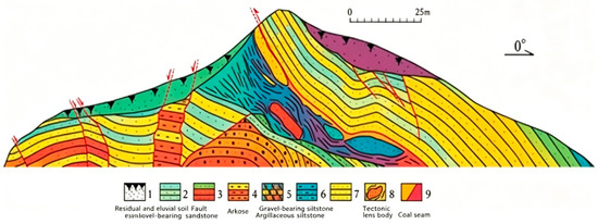
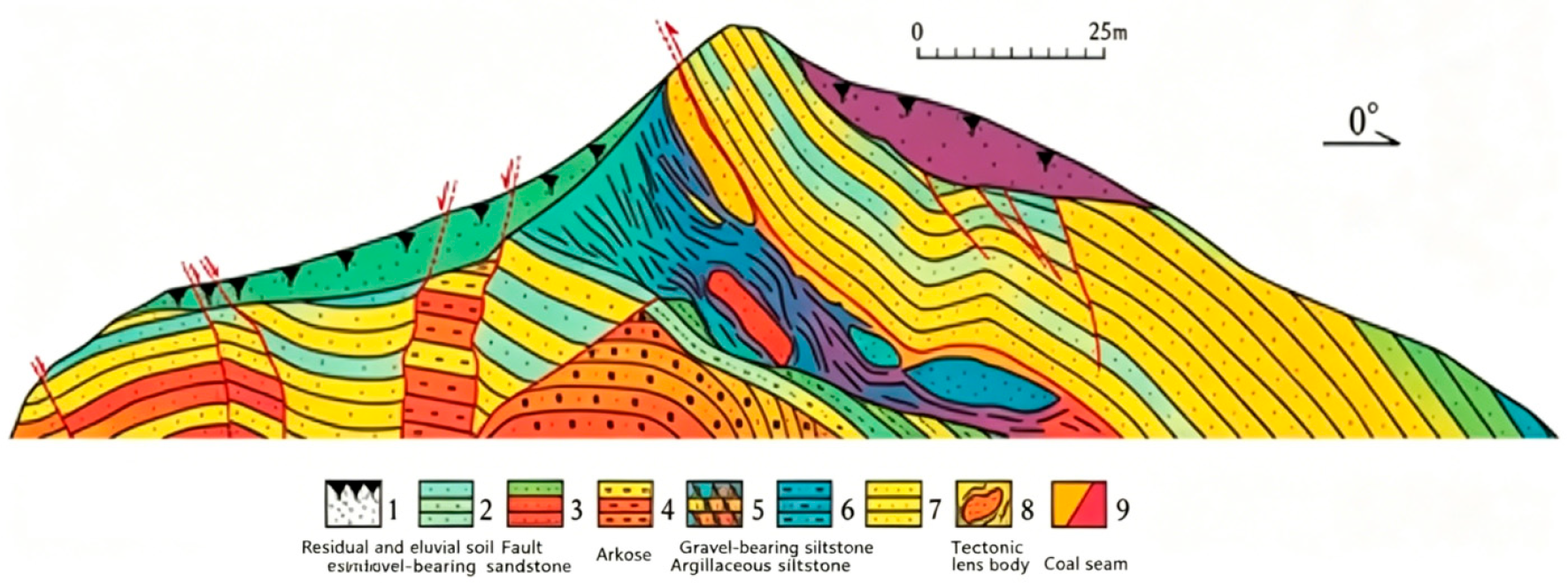
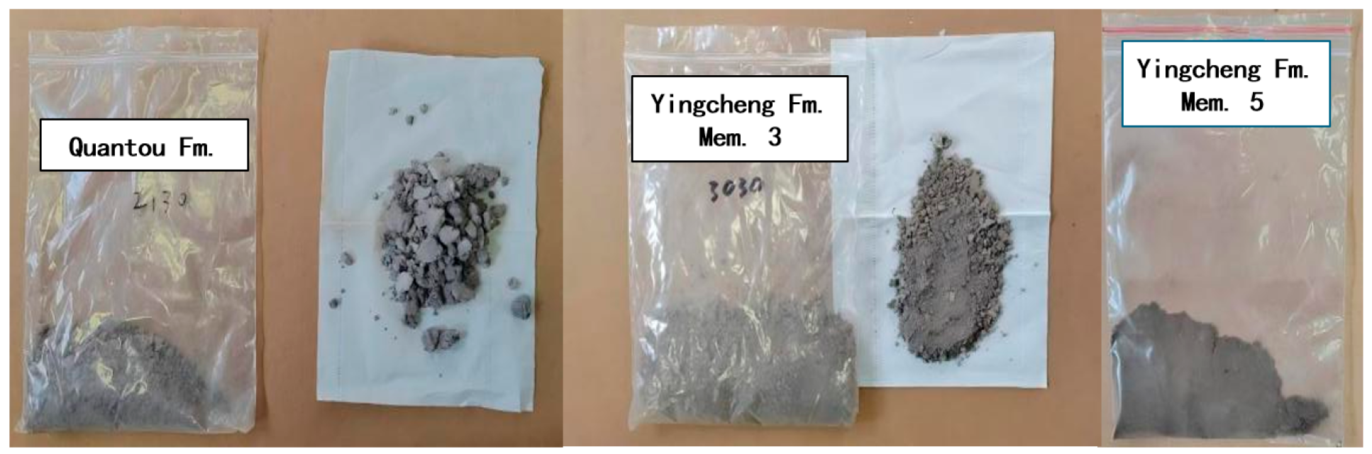
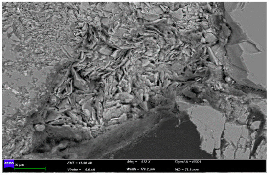
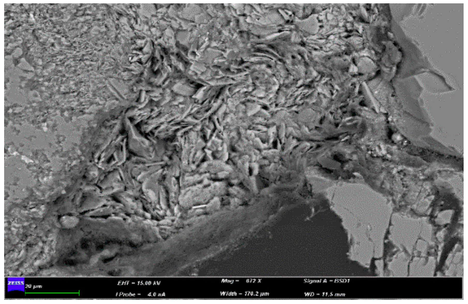
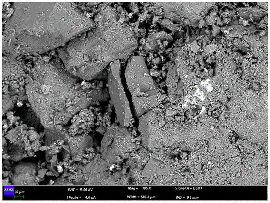
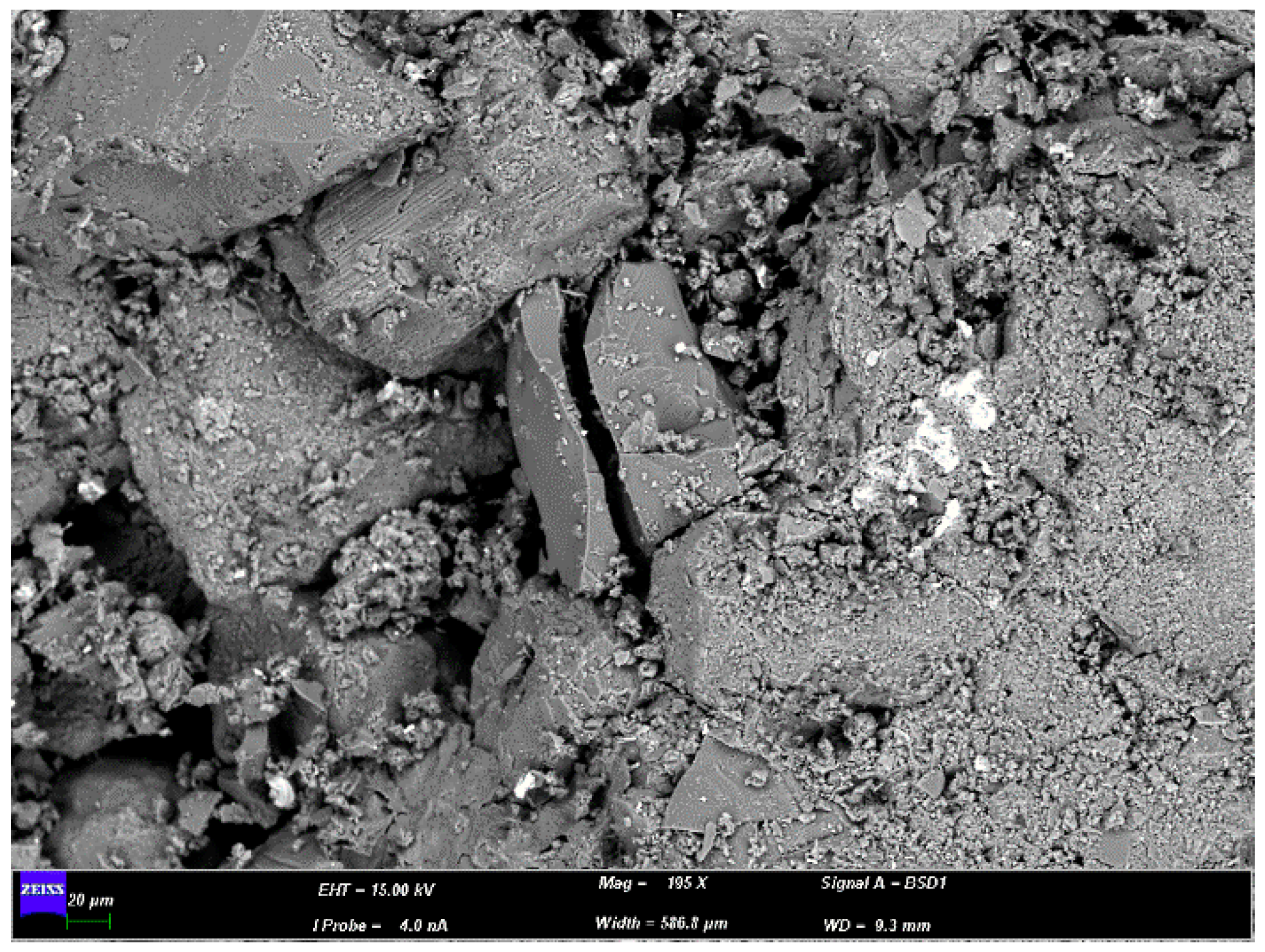
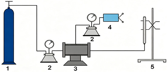
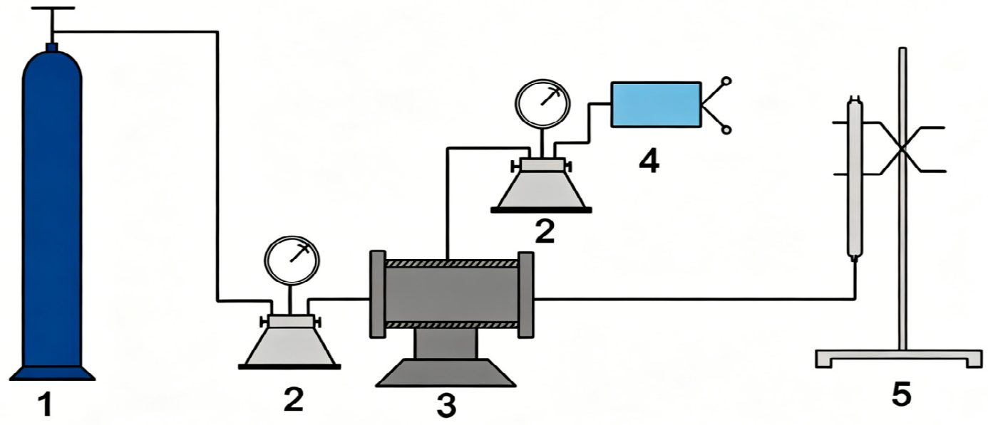
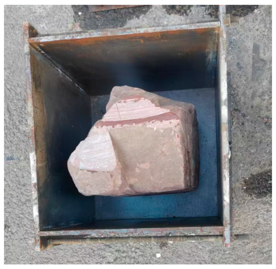
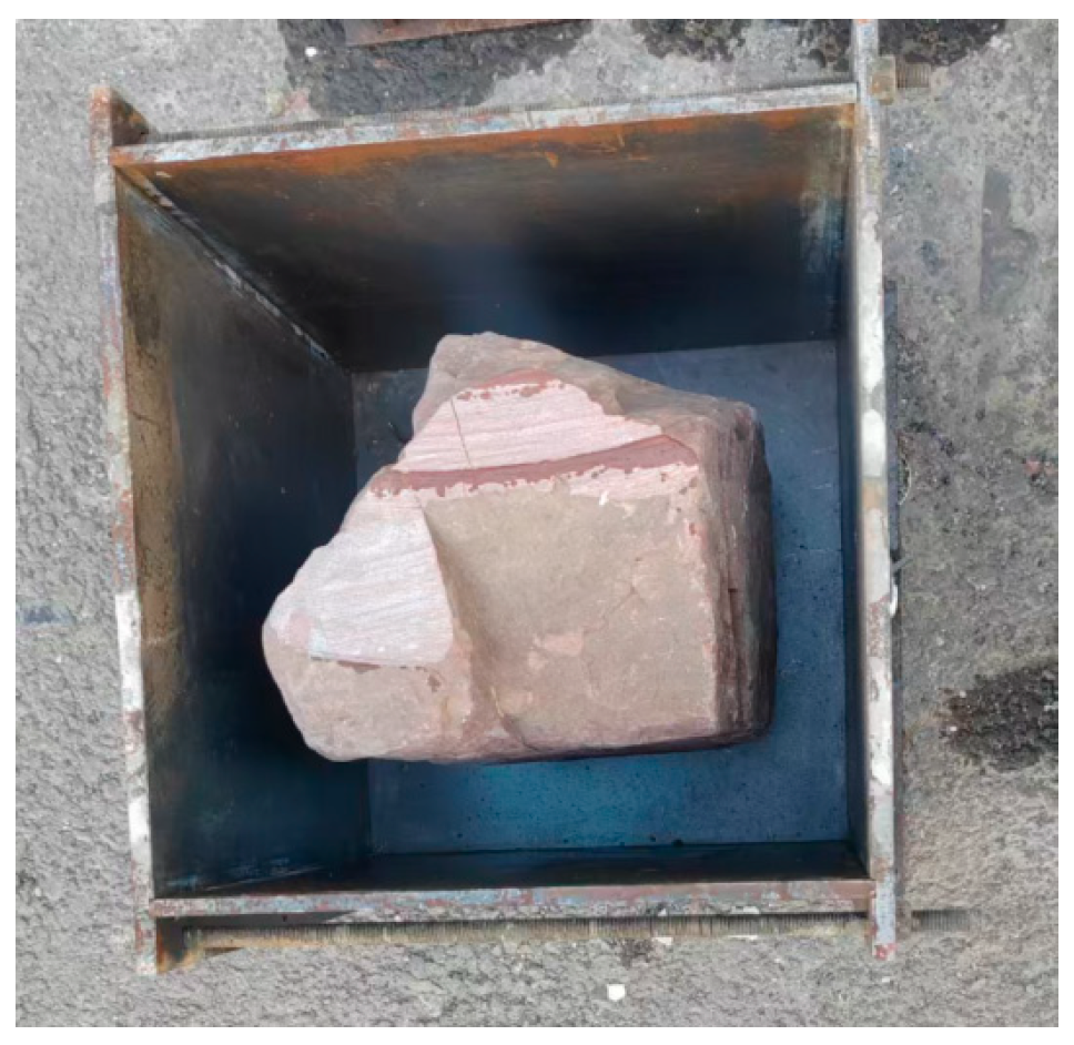
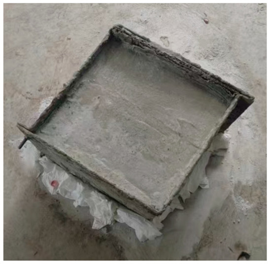
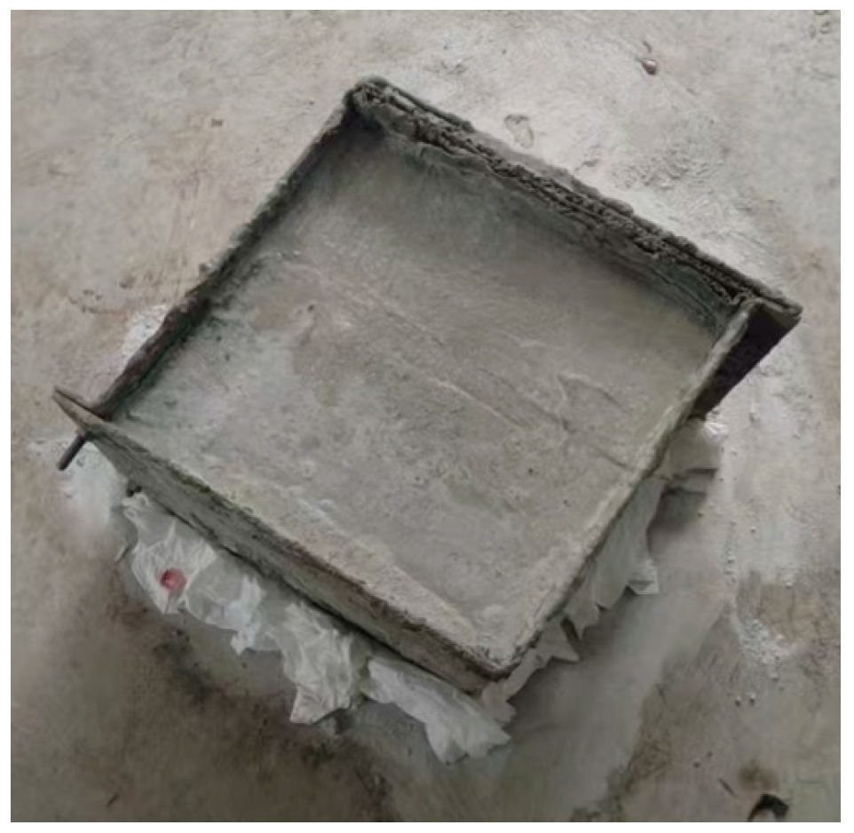
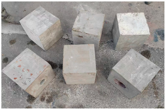
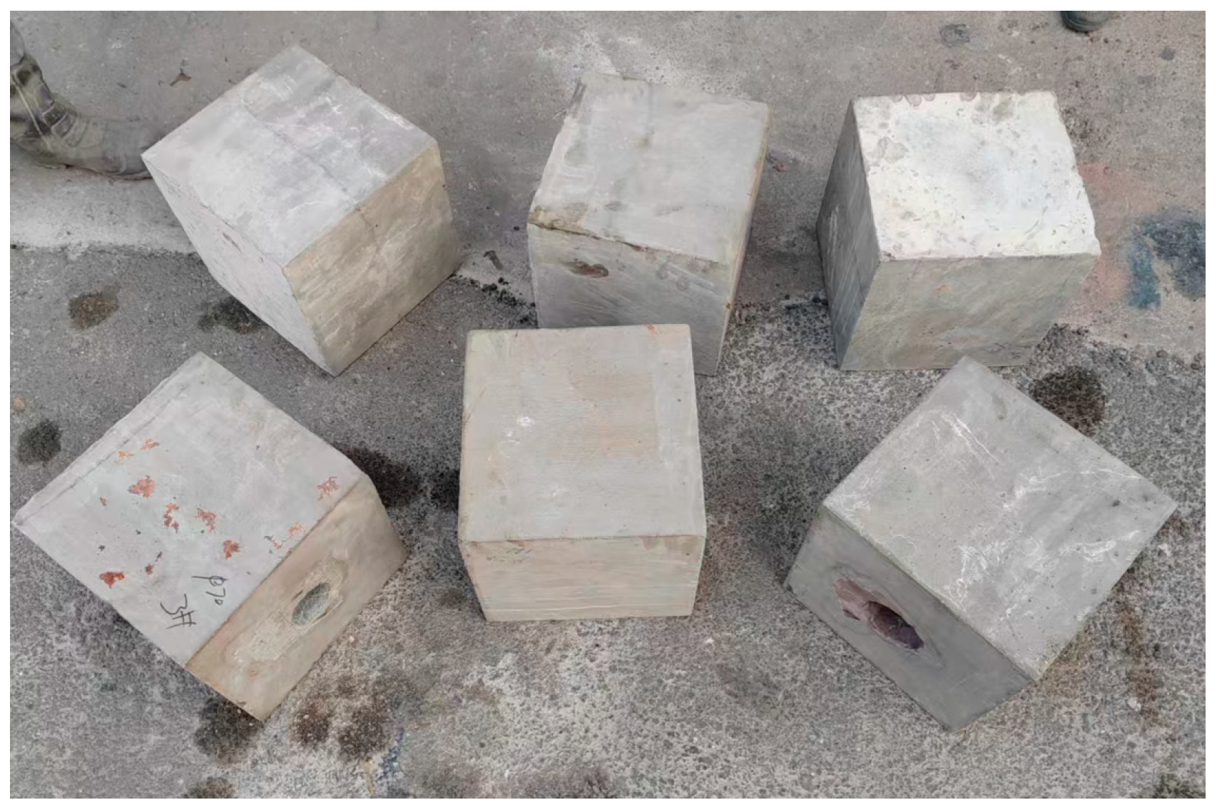
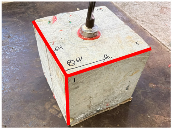
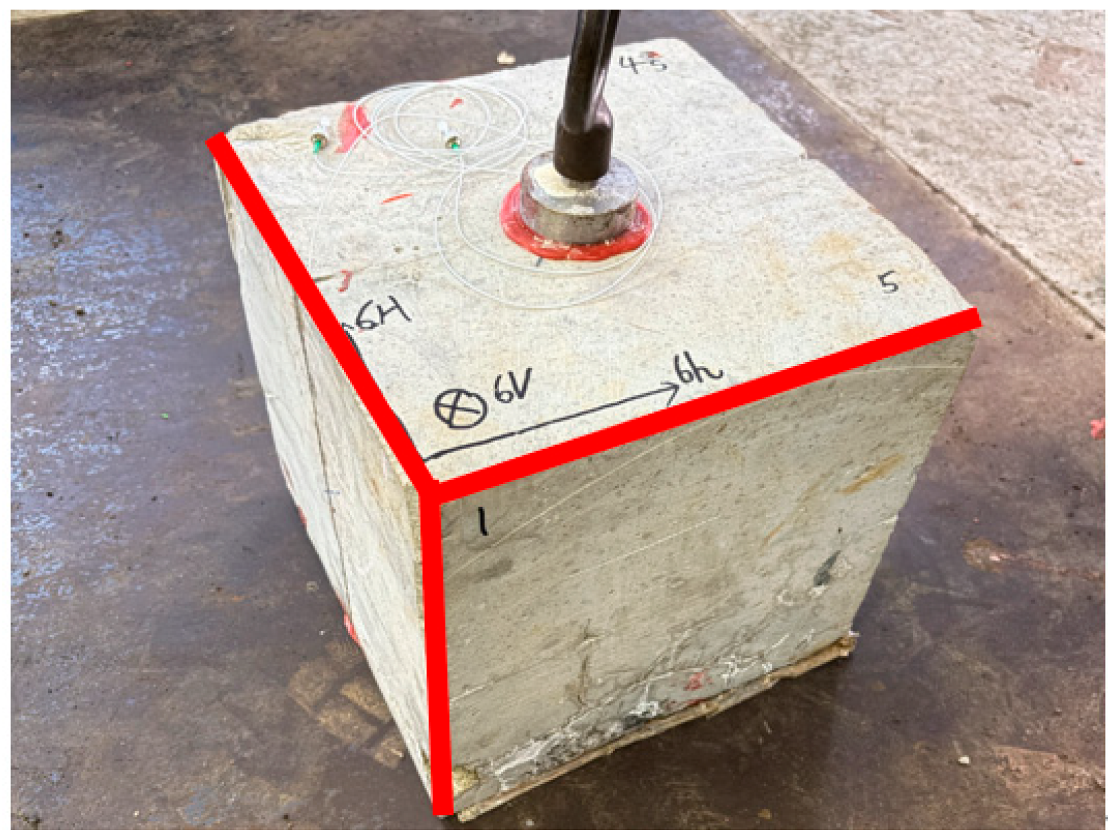
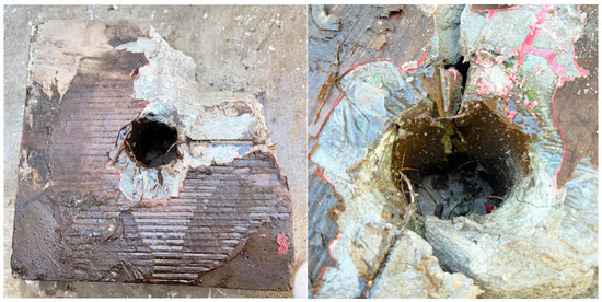
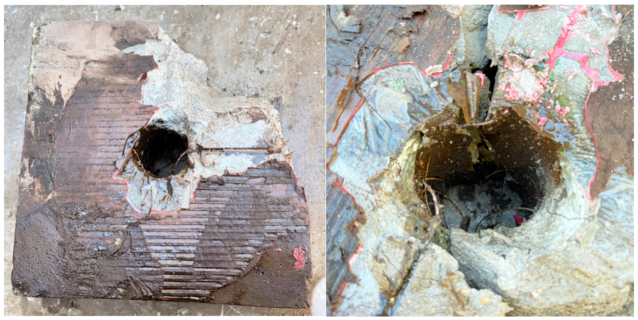
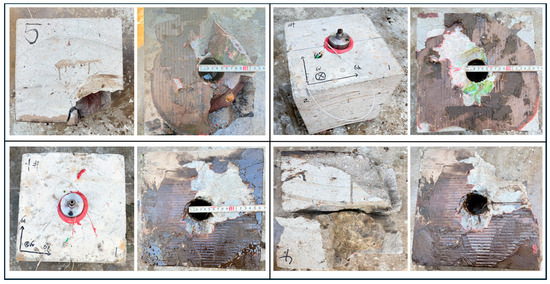
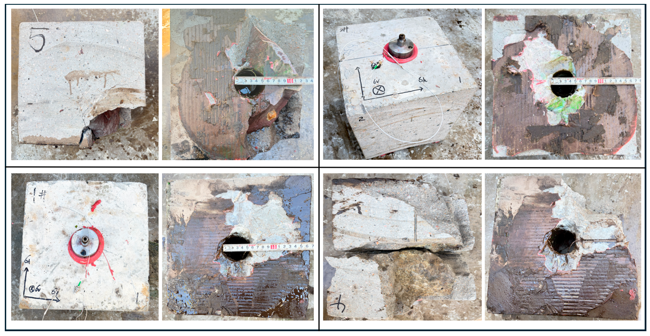
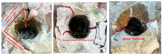
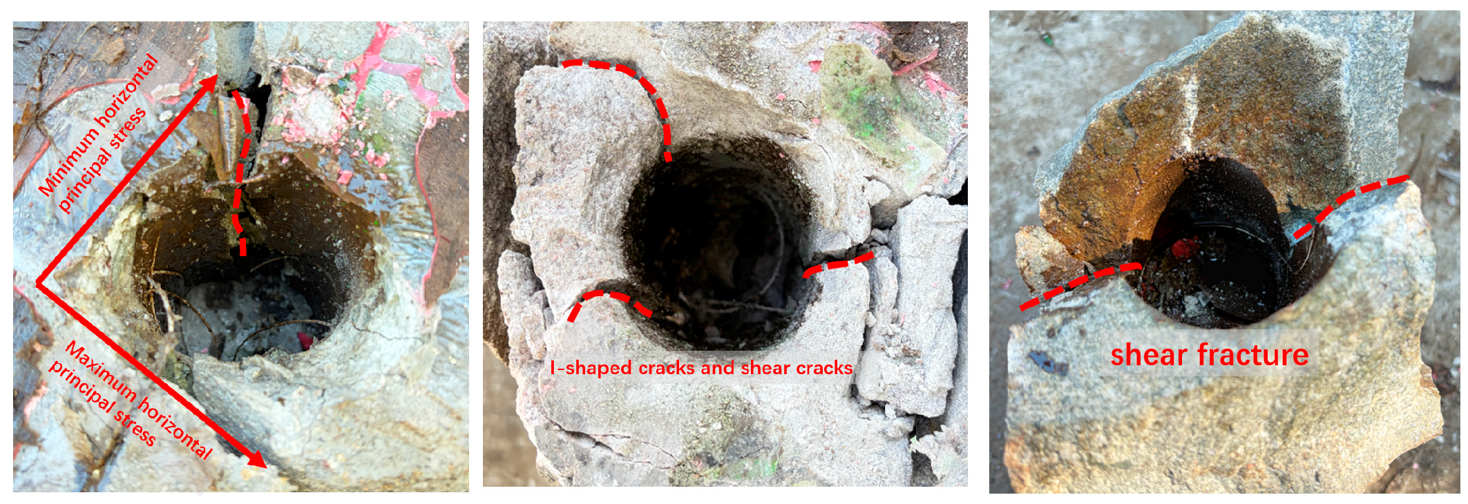
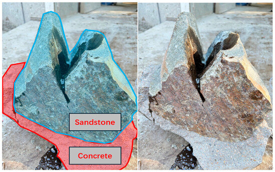
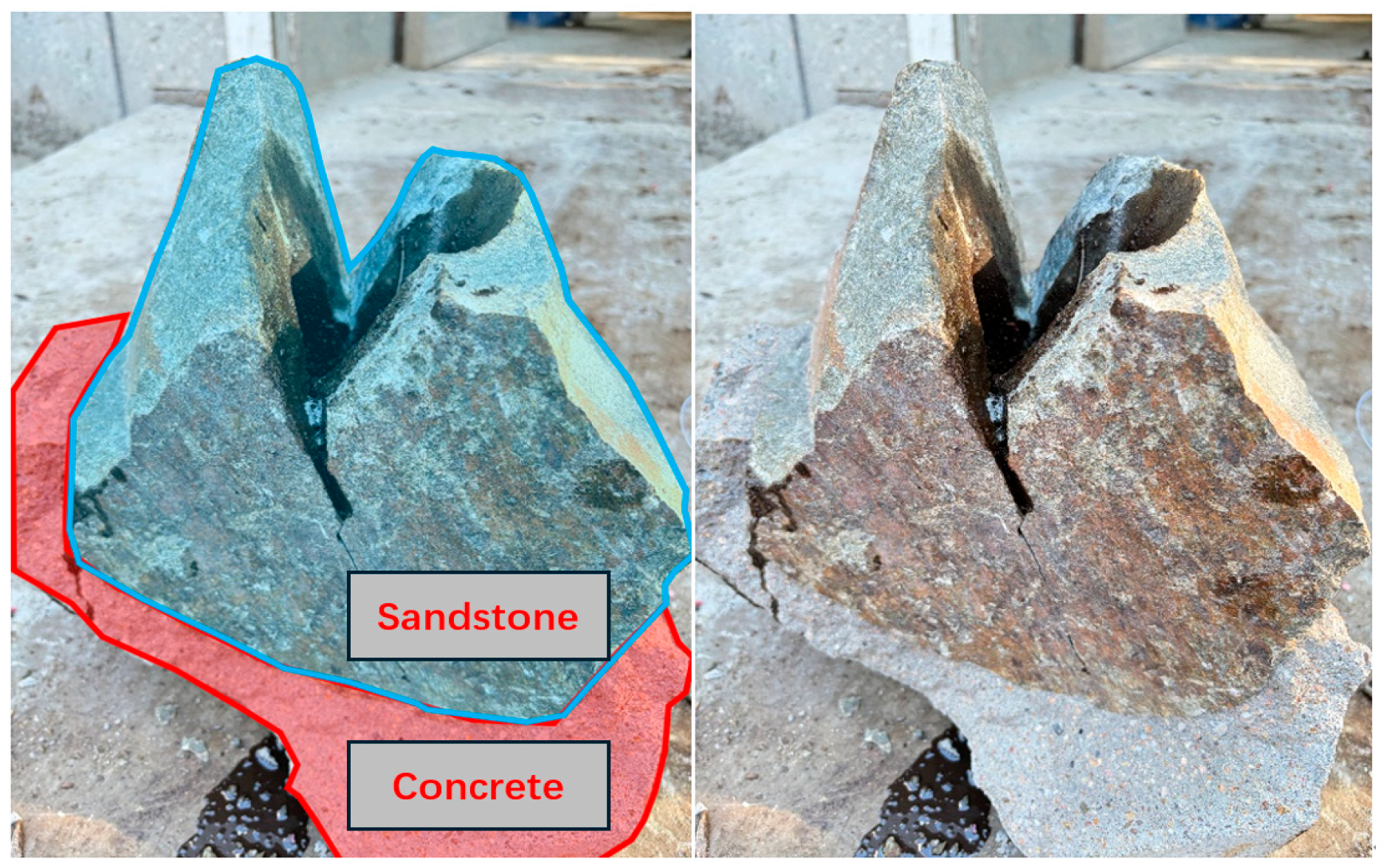
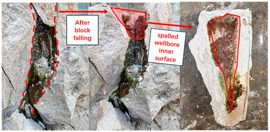
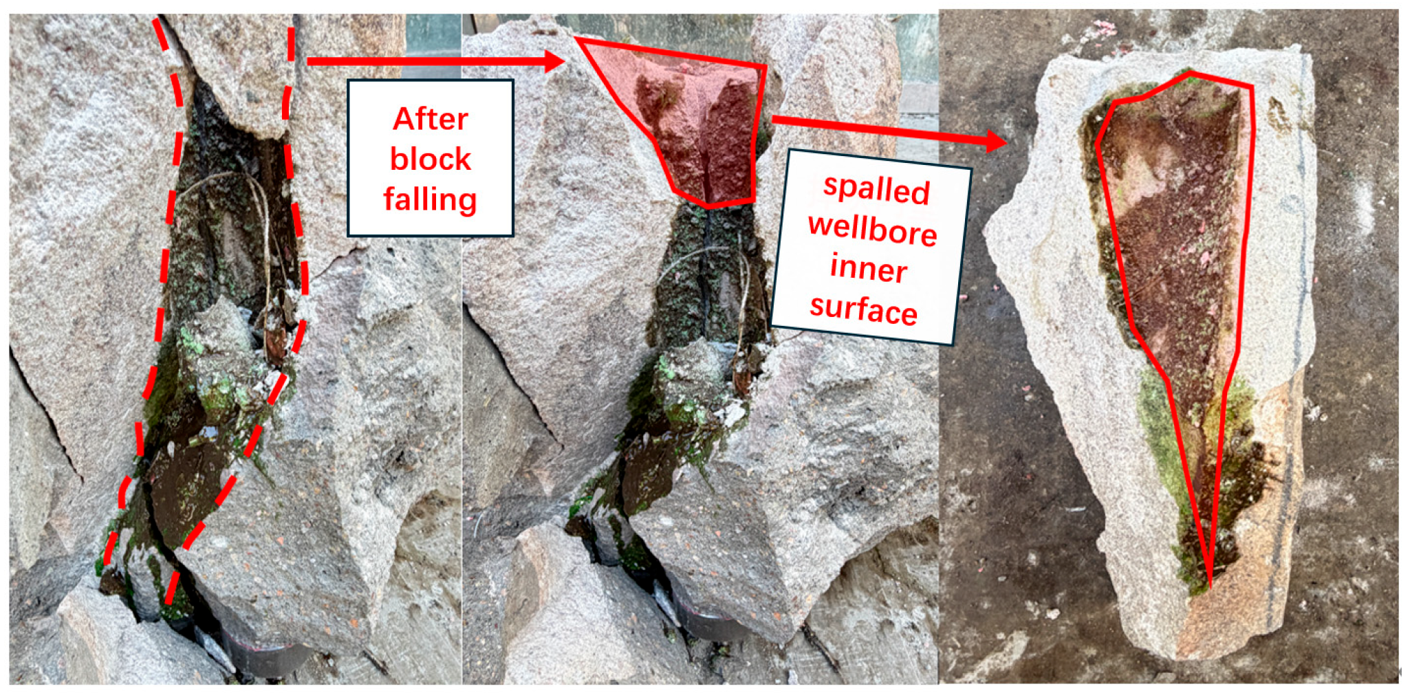
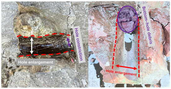
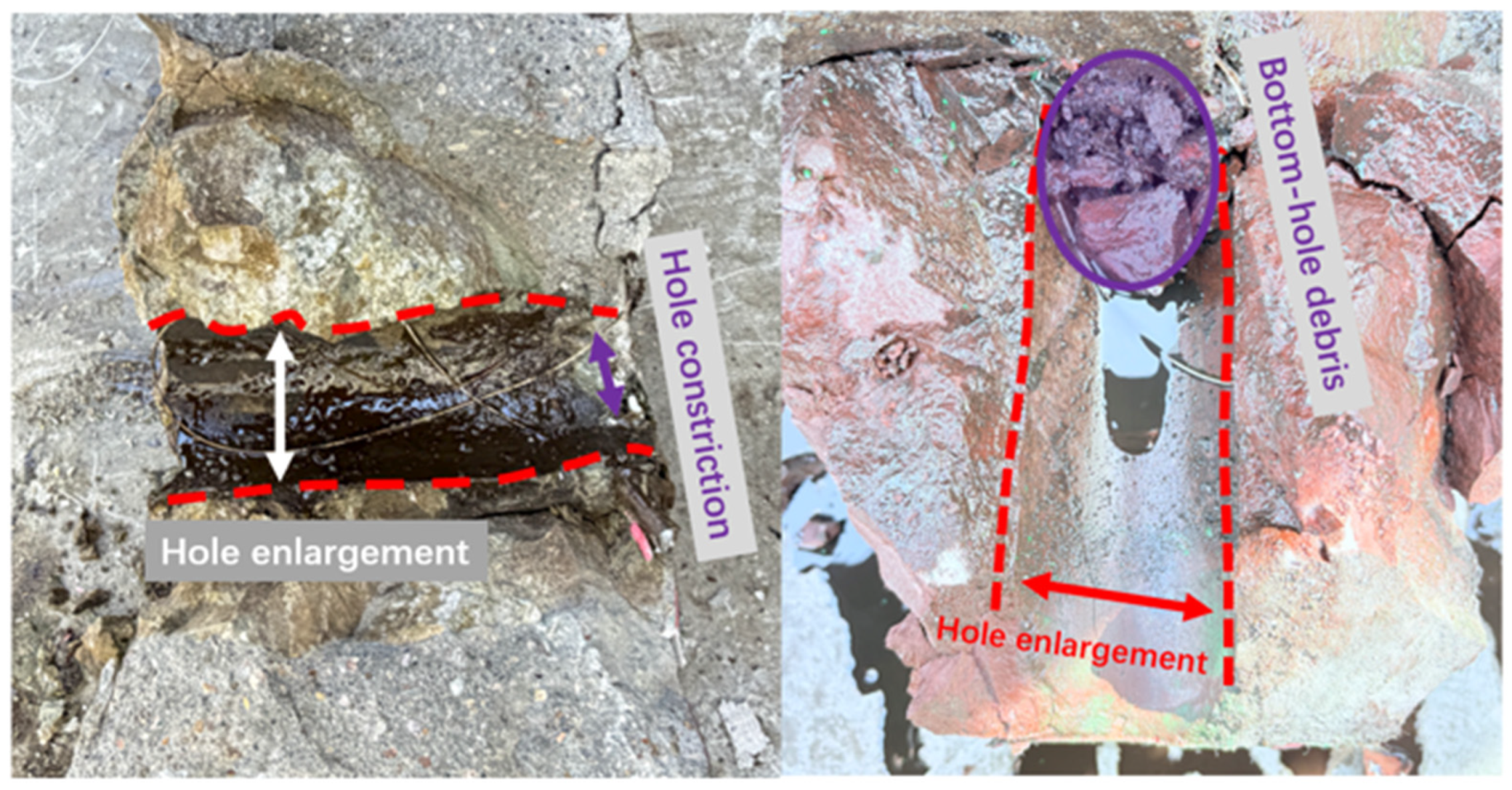
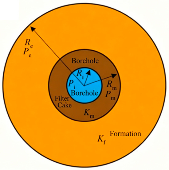
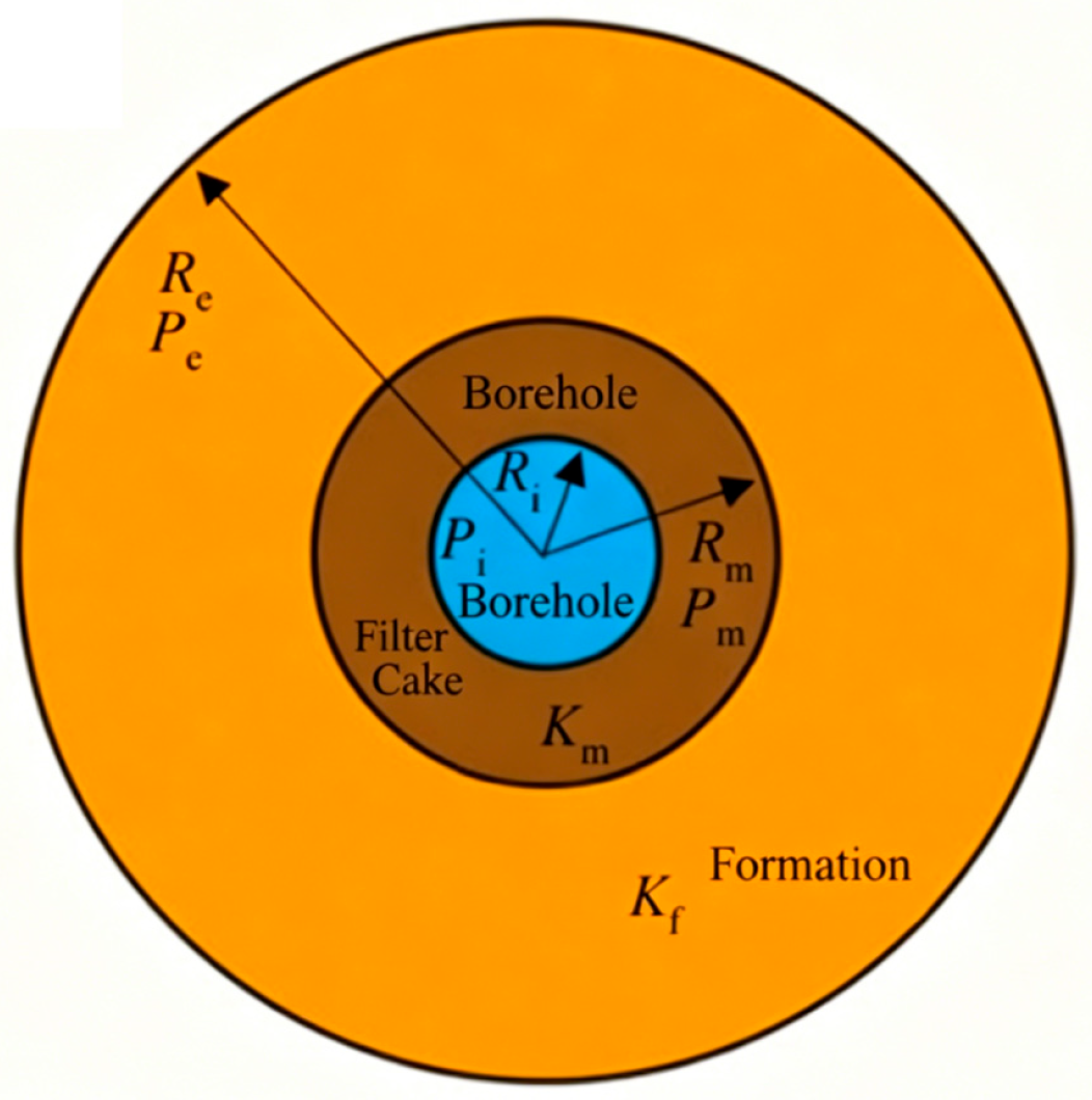
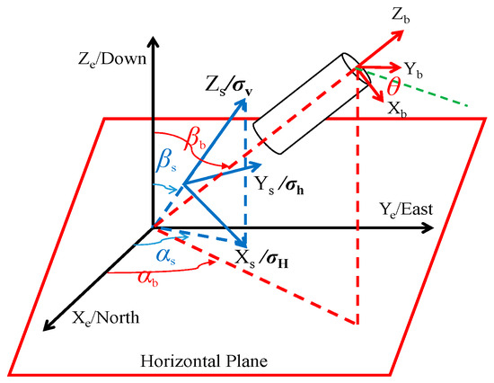
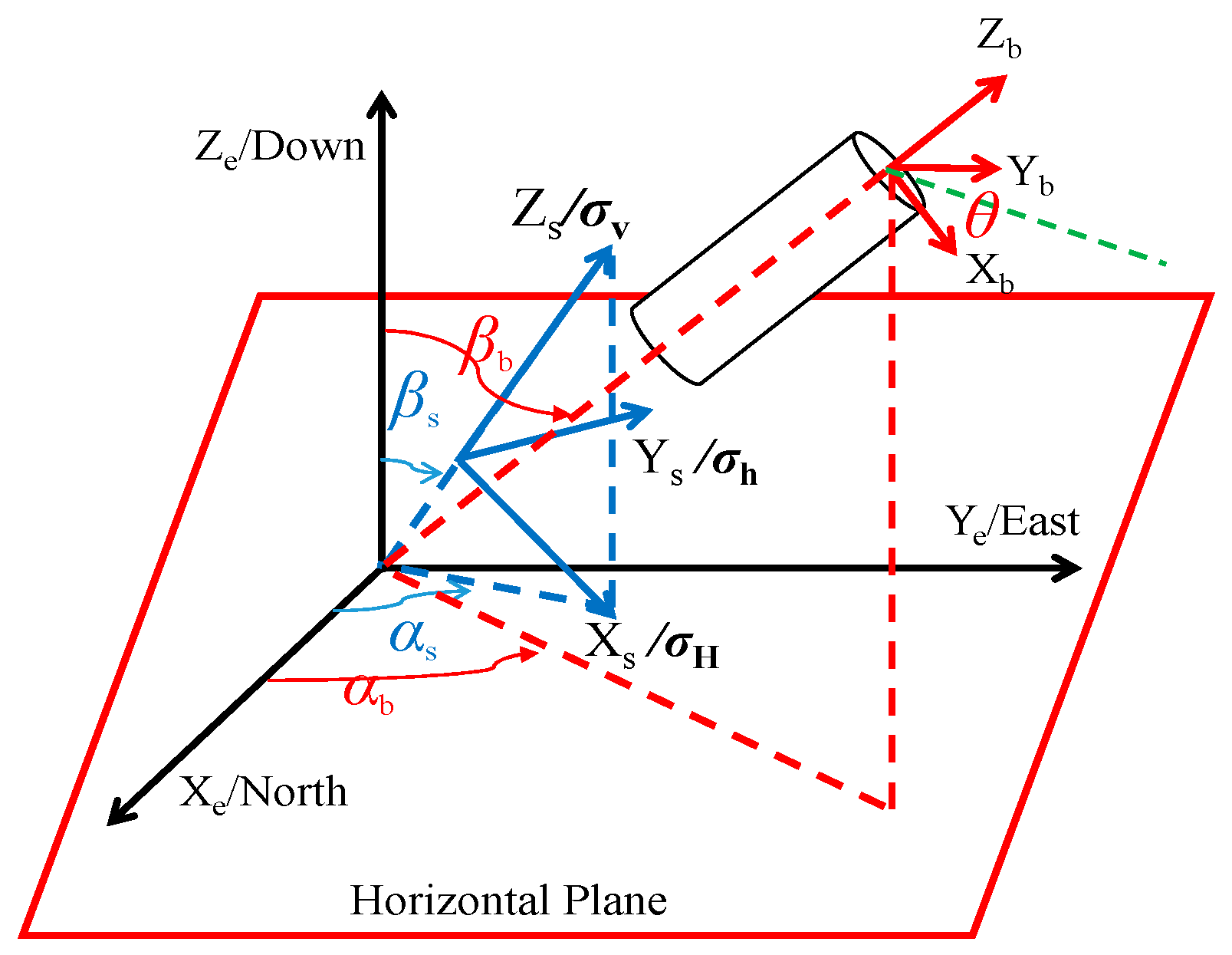
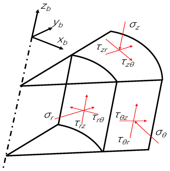
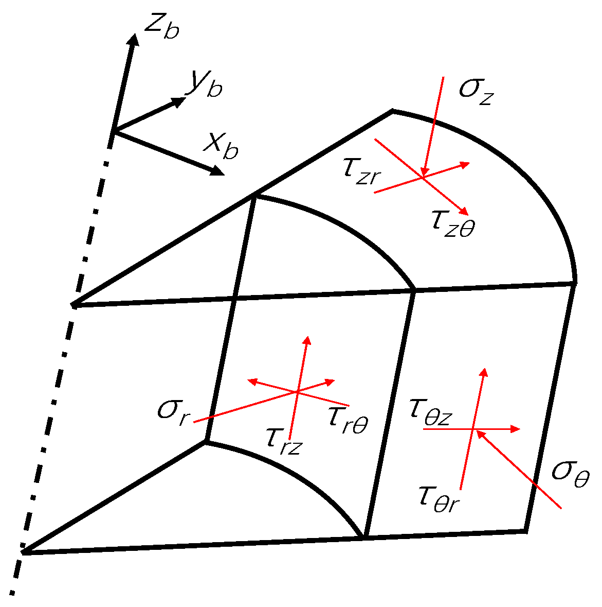
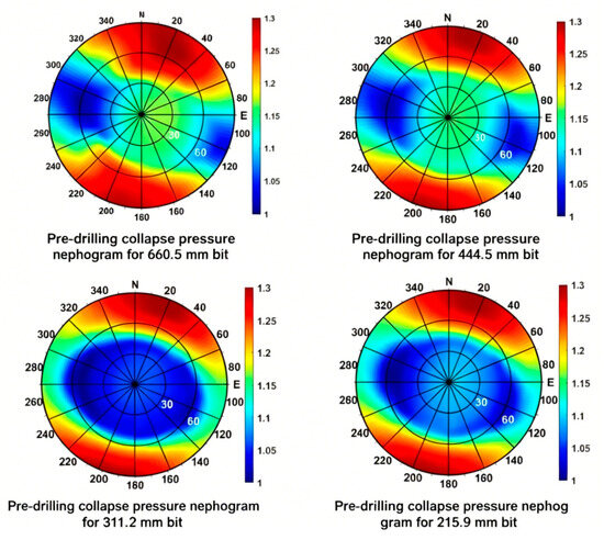
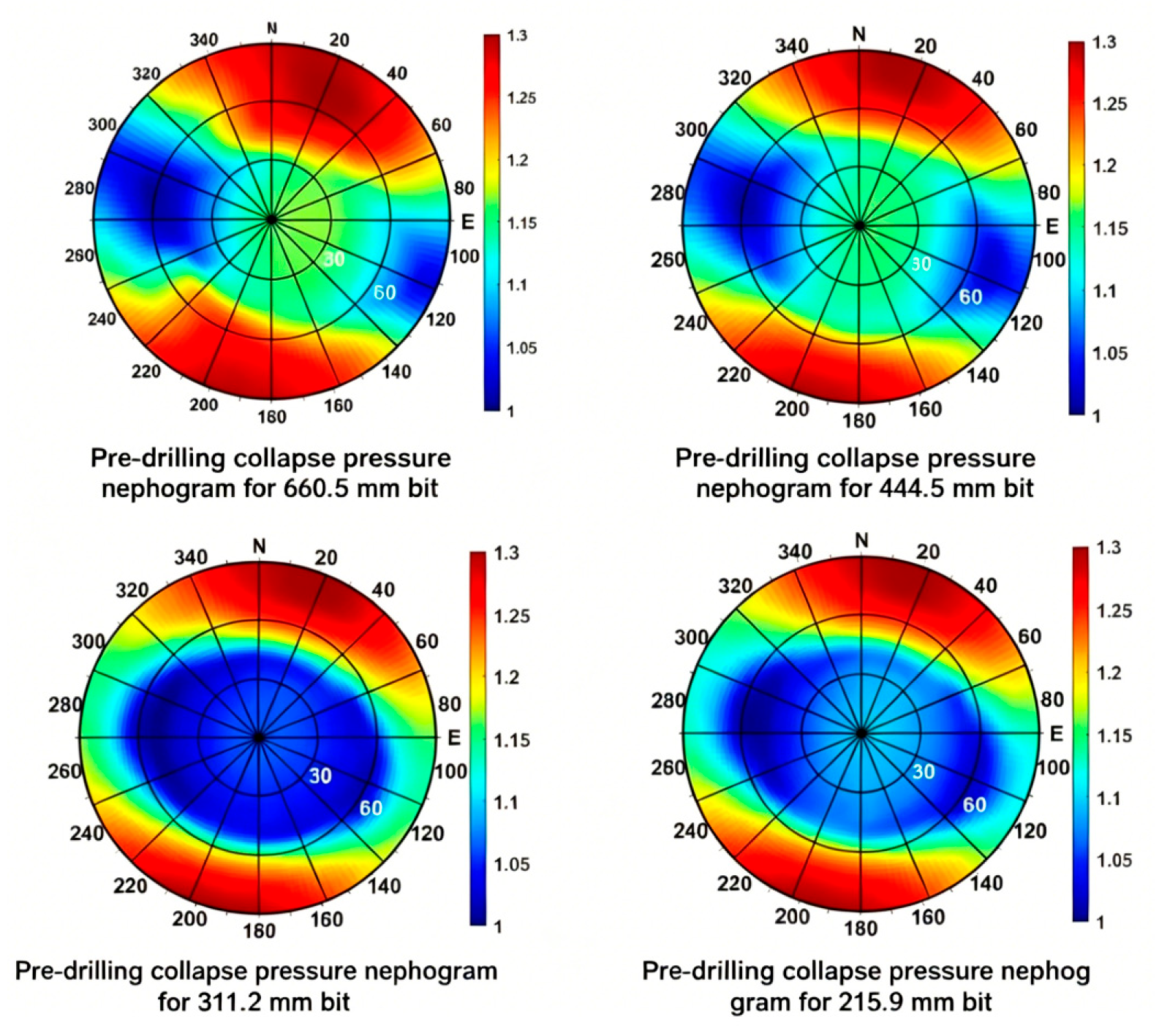
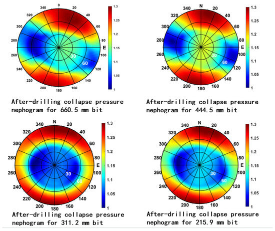
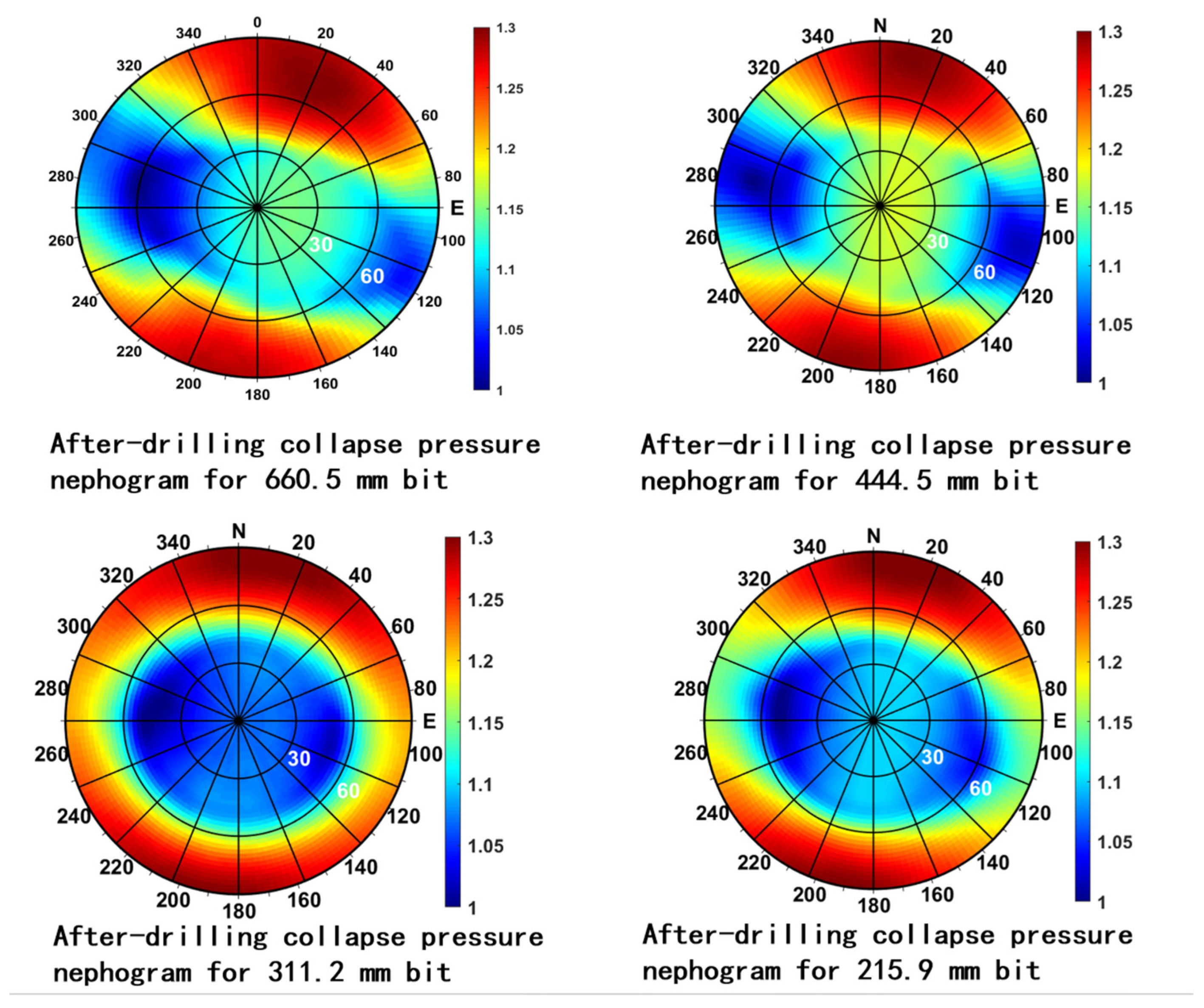
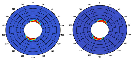
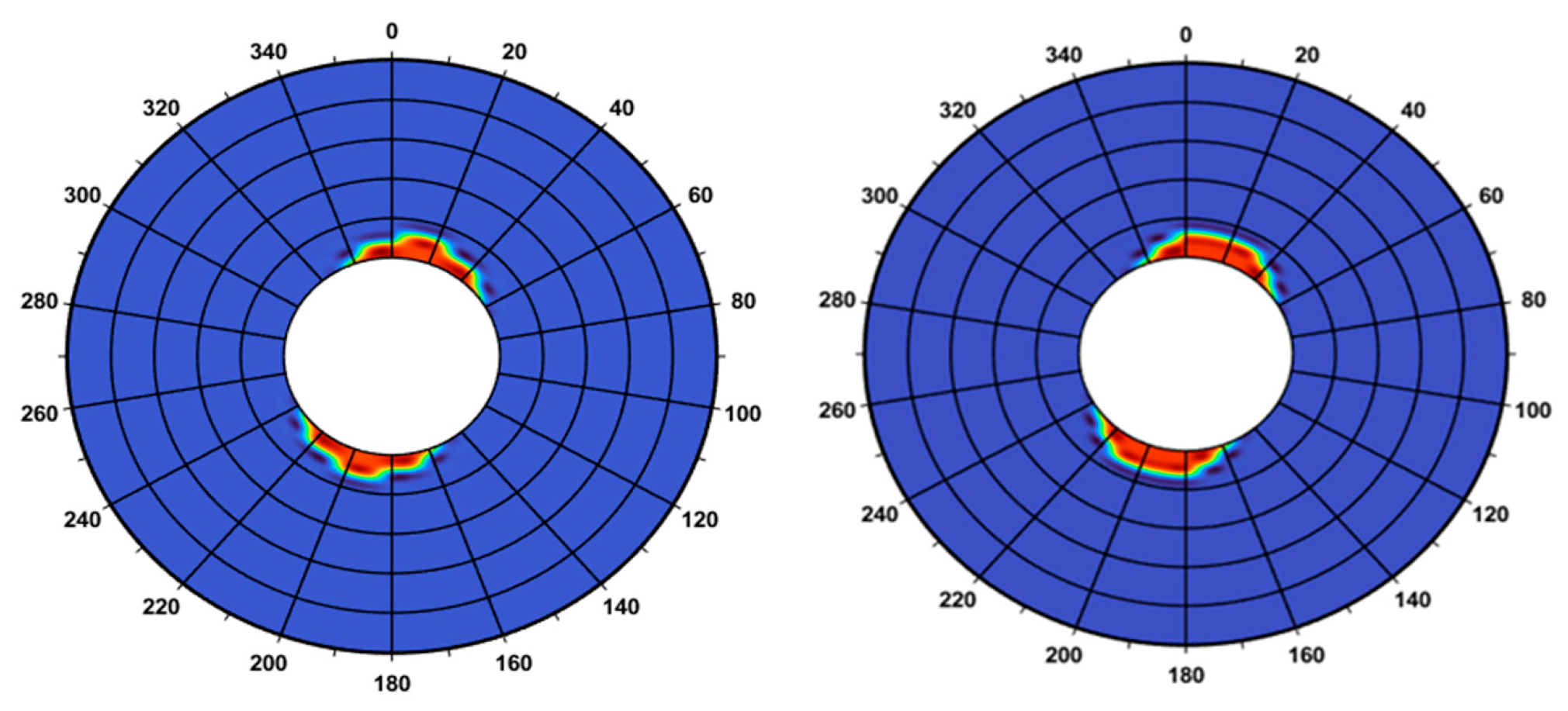
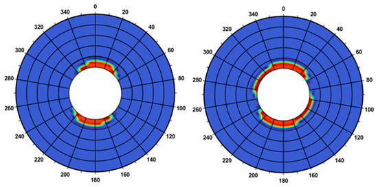
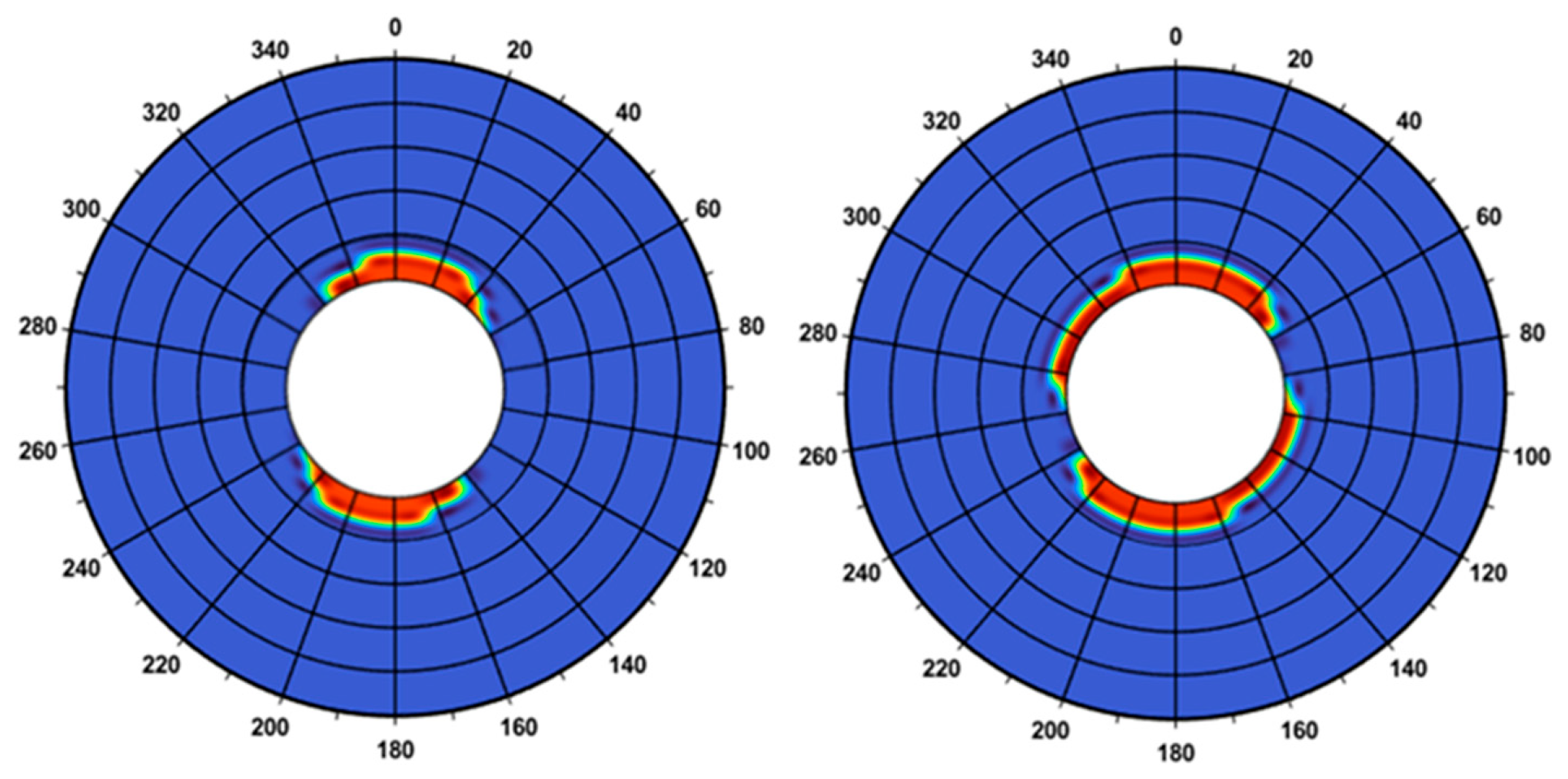
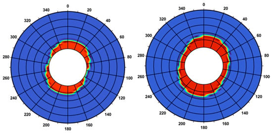
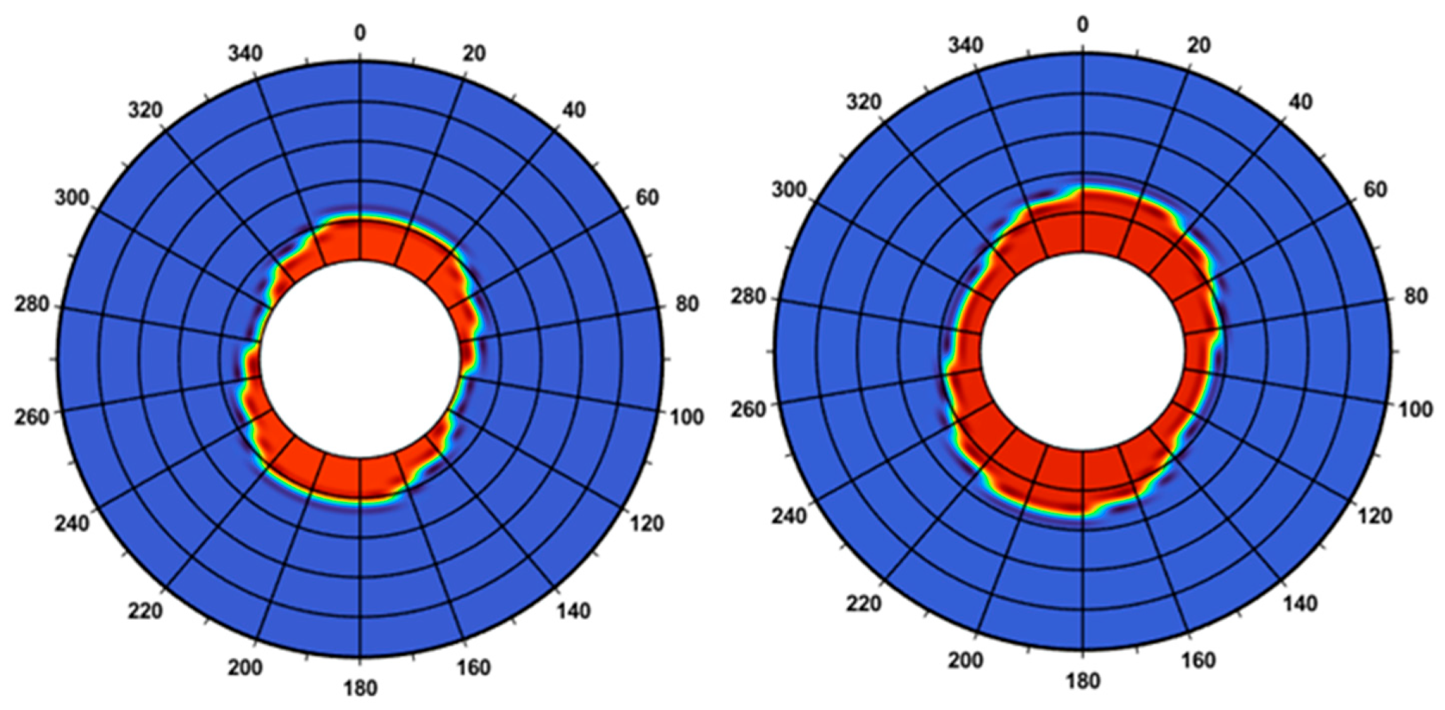
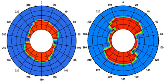
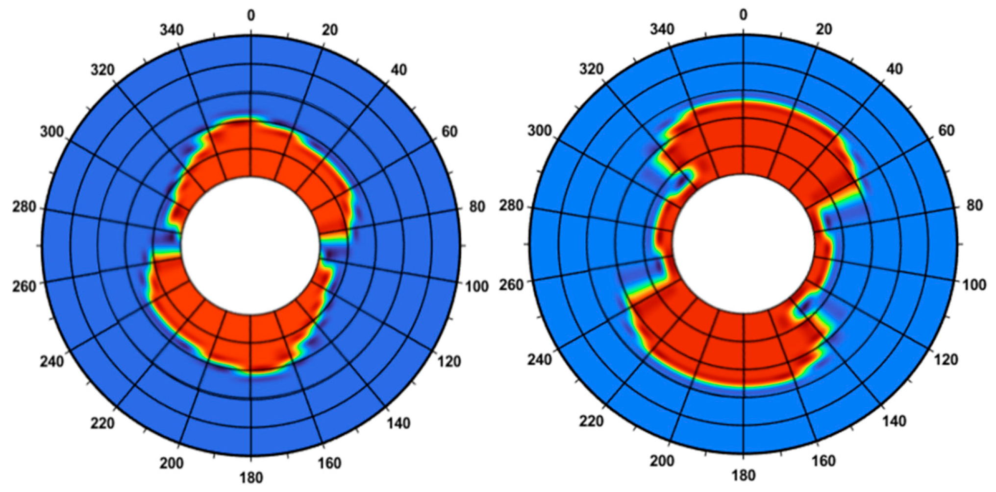
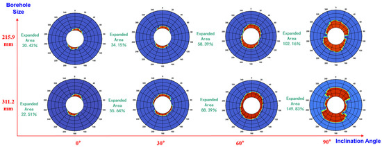
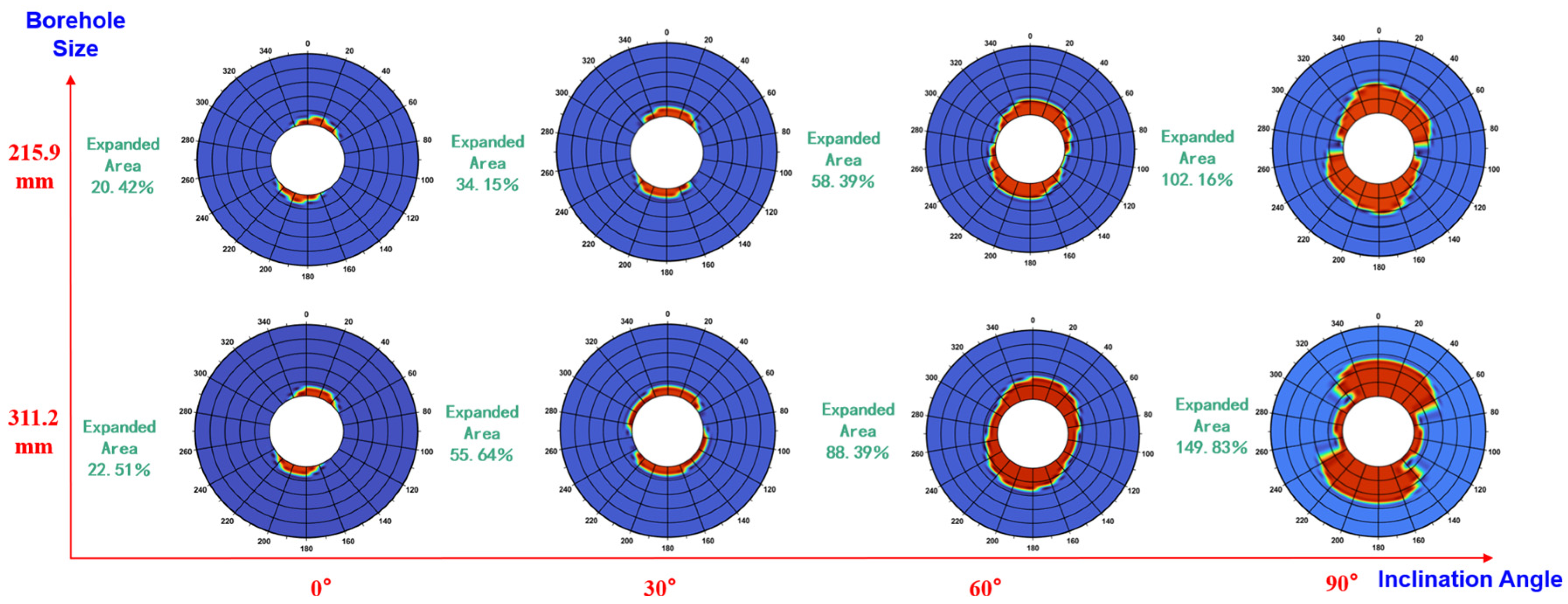

Disclaimer/Publisher’s Note: The statements, opinions and data contained in all publications are solely those of the individual author(s) and contributor(s) and not of MDPI and/or the editor(s). MDPI and/or the editor(s) disclaim responsibility for any injury to people or property resulting from any ideas, methods, instructions or products referred to in the content. |
© 2026 by the authors. Licensee MDPI, Basel, Switzerland. This article is an open access article distributed under the terms and conditions of the Creative Commons Attribution (CC BY) license.