


Abstract
Maintaining wellbore stability in deep and ultra-deep formations demands plugging agents capable of sealing nano- to micro-scale pores under high-temperature conditions. A core–shell nano-plugging agent (CSP) was synthesized via emulsion polymerization using KH-570-modified nano-SiO2 as the rigid core and a poly(styrene-co-butyl acrylate-co-methyl methacrylate) terpolymer as the deformable shell. CSP particles had a mean diameter of 196.5 nm (polydispersity index, PDI = 0.183) and an onset decomposition temperature of 342 °C. Compatibility tests at 180 °C confirmed that 3 wt% CSP caused no adverse changes in the rheology or emulsion stability of the oil-based drilling fluid (OBM). At 180 °C, CSP reduced the high-temperature high-pressure (HTHP) filtrate loss by 64.4% and the permeability plugging apparatus (PPA) filtrate loss by 66.1%. Sand-disk tests elevated the breakthrough pressure from 1.5 to 9.2 MPa. Core displacement on sandstone cores achieved a plugging rate of 98.30%, and pressure transmission tests on natural shale cores extended the 50% equalization time by 7.8-fold. Comparative evaluation confirmed that the core–shell architecture consistently outperformed nano-SiO2 alone, polymer alone, and their physical blend. Low-temperature N2 adsorption provided direct evidence of pore sealing, with the treated-shale Brunauer–Emmett–Teller (BET) surface area and total pore volume reduced by about 62% (12.6 to 4.8 m2/g and 0.0325 to 0.0121 cm3/g, respectively). Scanning electron microscopy of the shale surface before and after treatment further provided direct visual evidence of pore sealing, showing the open, porous matrix being converted into a dense, compacted filter cake. Filter-cake thickness measurements are consistent with a proposed three-stage plugging mechanism—bridging, deformation filling, and thermal compaction—driven by the complementary roles of the rigid core and the deformable shell. These findings indicate that CSP merits further evaluation as a high-temperature plugging agent for wellbore stabilization in deep shale formations.
1. Introduction
The rapid expansion of deep and ultra-deep well drilling for unconventional oil and gas resources has introduced formidable challenges to wellbore stability [1,2,3]. Shale formations encountered at depths exceeding 4000 m typically exhibit extensive development of micro-fractures and nano-scale pores, with aperture sizes predominantly ranging from 50 to 500 nm [4,5]. During drilling operations, pressure differentials drive drilling fluid invasion through these pathways, triggering pore pressure elevation near the wellbore, mechanical weakening of the rock matrix, and ultimately wellbore instability events, such as borehole collapse and stuck pipe [6,7,8].
Oil-based drilling fluids (OBMs) have become the preferred choice for drilling shale formations owing to their superior shale inhibition characteristics, lubricity, and thermal stability [9,10]. Unlike water-based systems, OBMs suppress clay hydration and swelling by preventing direct water contact with the formation. Nevertheless, the continuous oil phase can still penetrate micro-fractures and nano-pores under downhole pressure, causing pressure transmission into the near-wellbore region. Consequently, effective plugging of these nano- to micro-scale pathways remains essential even when OBMs are employed [11,12].
Conventional plugging agents for drilling fluids, including calcium carbonate particles, asphalt, and sulfonated lignite, have particle sizes in the micrometer-to-millimeter range and are inherently unable to enter nano-scale pores [13,14]. Over the past decade, nano-plugging agents have attracted considerable attention as candidates for sealing these fine pathways [15,16]. Inorganic nanoparticles, such as nano-SiO2, nano-TiO2, and nano-ZnO, exhibit small particle sizes and high surface areas, enabling penetration into nano-pores [17]. However, their rigid nature prevents deformation under downhole pressure, limiting the sealing efficiency. Furthermore, unmodified inorganic nanoparticles are prone to aggregation in the oil phase, severely compromising their dispersibility in OBMs [18,19].
Organic polymer nanoparticles, including latex particles and gel microspheres, offer advantages of deformability and film-forming ability [20,21]. Under elevated pressures, these soft particles can deform to fill irregular pore geometries, creating effective seals. However, purely organic nanomaterials frequently suffer from insufficient thermal stability at temperatures exceeding 150 °C, where polymer chain degradation compromises the plugging integrity [22,23]. This temperature limitation restricts their applicability in deep and ultra-deep well environments where bottom-hole temperatures routinely exceed 180 °C.
Core–shell structured nanoparticles present an attractive strategy that combines the thermal stability and rigidity of an inorganic core with the deformability and oil-phase compatibility of a polymer shell [24,25]. Recent studies have explored SiO2@polymer core–shell particles for OBM plugging. A SiO2@poly(styrene-butyl acrylate) binary copolymer system demonstrated improved filtration control at 150 °C, while SiO2-reinforced polymer microspheres showed promising wellbore strengthening effects [26]. However, several critical gaps persist: (i) binary copolymer shells (e.g., St-BA) offer limited control over the glass transition temperature (Tg) and thus over the onset of deformation; (ii) the interplay between crosslinking density and deformability has not been systematically optimized; and (iii) the plugging mechanism has been inferred primarily from macroscopic performance rather than from direct microstructural evidence. Addressing these limitations requires a shell chemistry that offers a broader compositional window for balancing rigidity (via high-Tg monomers such as St and MMA) and deformability (via low-Tg monomers such as BA), combined with systematic evaluation of plugging performance and mechanistic analysis.
Specifically, the choice of a ternary St–BA–MMA shell rather than a conventional binary St–BA copolymer is motivated by three considerations. First, adding a third monomer widens the accessible glass transition window: the high-Tg rigid units (St, Tg ≈ 100 °C; MMA, Tg ≈ 105 °C) and the low-Tg flexible unit (BA, Tg ≈ −54 °C) can be balanced through the Fox equation to position Tg precisely below the bottom-hole temperature, so that the shell stays rigid during storage and surface handling yet turns viscoelastically deformable downhole. Second, the polar ester groups contributed by MMA raise the cohesive energy of the shell and strengthen its adhesion to the silica core, improving thermal stability relative to St–BA alone, whose narrower compositional range leaves less room to optimize rigidity and deformability simultaneously. Third, this balanced rigidity–deformability profile is the prerequisite for the bridging–deformation–compaction sealing sought at high temperature, allowing the shell to conform to irregular pore geometries without sacrificing the load-bearing integrity needed to withstand the large differential pressures of deep, hot formations. In summary, relative to a conventional binary St–BA shell, the St–BA–MMA terpolymer translates into three concrete, high-temperature-relevant advantages. (i) Thermal stability: the polar MMA ester units increase the cohesive energy of the shell and its adhesion to the silica core, which—together with the rigid core—raises the onset decomposition temperature by 57 °C (to 342 °C, Section 3.4) and preserves plugging integrity after aging at 180 °C, whereas purely St–BA shells offer a narrower window for such reinforcement. (ii) Deformability: the third monomer broadens the Fox-equation compositional window so that the shell Tg can be placed precisely (here, 53.6 °C, i.e., 126 °C below the 180 °C service temperature) to keep the particle rigid during storage and handling yet rubbery and pressure-deformable downhole—a rigidity/deformability balance that a binary St–BA pair, with its more constrained Tg range, cannot tune as freely. (iii) High-temperature plugging performance: this tunable balance is precisely what enables the bridging–deformation–compaction sealing, and it underpins the 64.4% HTHP and 66.1% PPA filtrate-loss reductions and the 9.2 MPa sand-disk breakthrough pressure reported below (Section 3.6.1, Section 3.6.2, Section 3.6.3, Section 3.6.4 and Section 3.6.5), which exceed those of the corresponding single-component and physically blended controls.
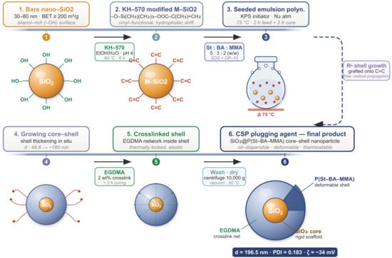
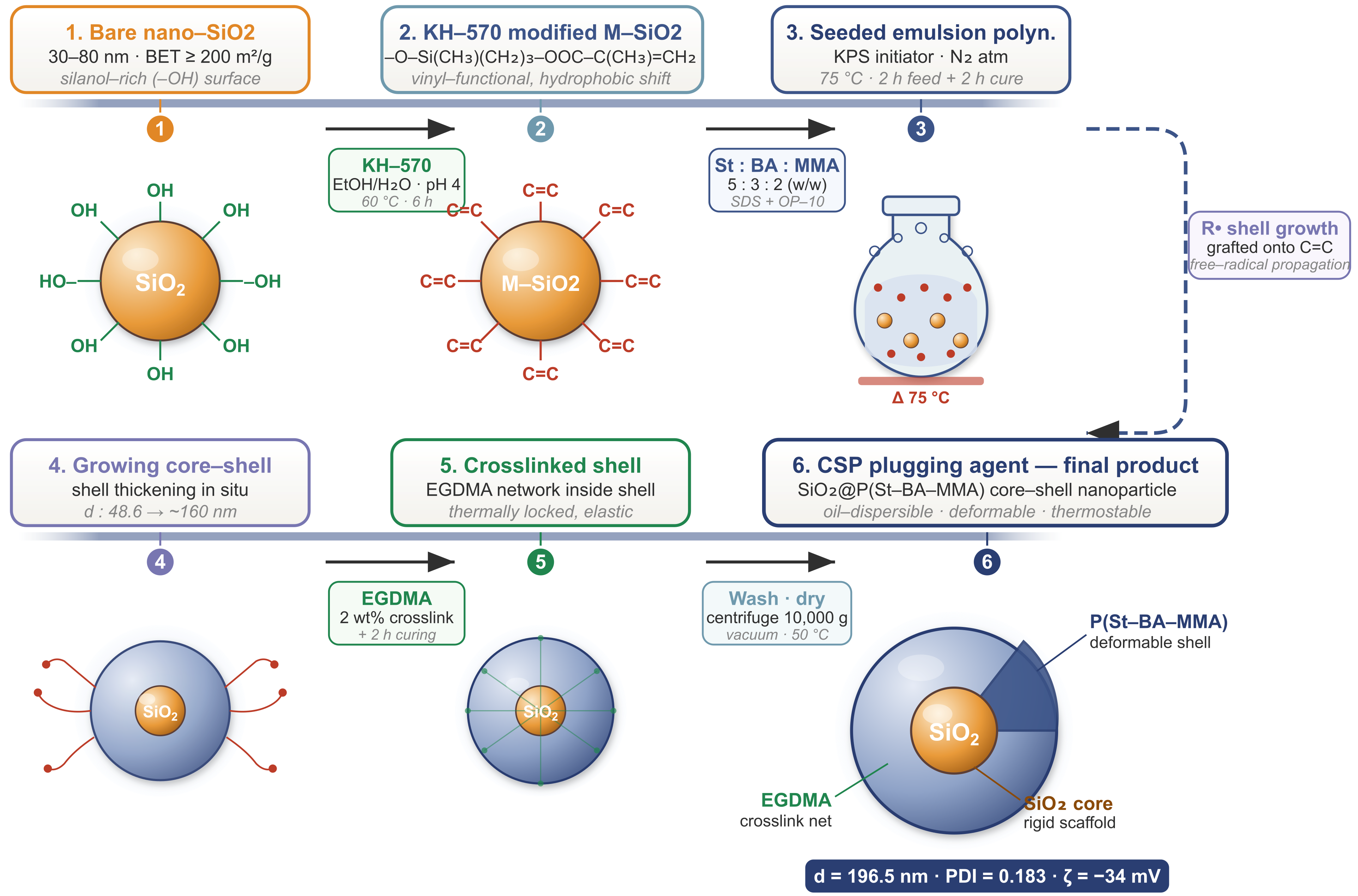
In this work, a core–shell nano-plugging agent (CSP) was developed by coating KH-570-modified nano-SiO2 particles with a poly(styrene-co-butyl acrylate-co-methyl methacrylate) copolymer shell via emulsion polymerization (Figure 1). The synthesis conditions were systematically screened through single-factor experiments. The resulting CSP was characterized by Fourier-transform infrared spectroscopy (FTIR), transmission electron microscopy (TEM), dynamic light scattering (DLS), and thermogravimetric analysis (TGA), with the sealed shale surface further imaged by scanning electron microscopy (SEM), and its plugging performance was evaluated through HTHP filtration, PPA tests, sand-disk plugging, core displacement, and pressure transmission experiments.
Figure 1.
Schematic illustration of CSP synthesis: (a) surface modification of nano-SiO2 with KH-570 and subsequent polymer coating via emulsion polymerization; (b) detailed seeded emulsion polymerization process showing seed dispersion, monomer feeding, shell growth, and final CSP product.
2. Materials and Methods
2.1. Materials
The main reagents and instruments used in this study are summarized in Table 1.
Table 1.
Main reagents and instruments.
All reagents listed in Table 1 were of analytical grade unless otherwise specified. St, BA, and MMA were purified through inhibitor-removal columns before use. The OBM base formulation consisted of 280 mL 5# white oil, 15 g primary emulsifier, 8 g secondary emulsifier, 25 g organoclay, 70 mL CaCl2 brine (25 wt%), 20 g fluid loss reducer, 10 g lime, and barite weighted to 1.50 g/cm3.
2.2. Surface Modification of Nano-SiO2
Nano-SiO2 (10 g) was dispersed in 200 mL of 95:5 (v/v) ethanol–water by ultrasonication (30 min), the pH was adjusted to 4.0 with acetic acid, and 3 g KH-570 was added dropwise at 60 °C for 6 h under mechanical stirring. The product was centrifuged, washed with ethanol, and vacuum-dried at 60 °C for 12 h. TGA indicated a grafted organic weight loss of 8.6 ± 0.4 wt% (200–500 °C, n = 3), corresponding to ~2.1 molecules/nm2.
2.3. Synthesis of CSP
CSP was prepared via seeded emulsion polymerization. Modified nano-SiO2 (0.75 wt% relative to total monomer) was dispersed in deionized water containing SDS:OP-10 (3:2, total 5 wt%) by ultrasonication (20 min). A monomer mixture of St:BA:MMA = 5:3:2 (total 40 wt%) with EGDMA (0.30 wt%) was pre-emulsified separately. The seed dispersion was heated to 75 °C under N2, KPS (0.10 wt%) was injected, and the monomer emulsion was fed dropwise over 2 h, followed by 2 h of post-polymerization. The latex was demulsified with CaCl2 (5 wt%), centrifuged (8000 rpm, 15 min), washed, vacuum-dried at 60 °C for 24 h, and ground to a fine powder (200-mesh). This dried powder was used in all OBM evaluations. The yield was 92.4 ± 1.8% (n = 3).
2.4. Preparation of Control Samples
Three controls were prepared: (i) KH-570-modified nano-SiO2 powder; (ii) pure polymer P(St–BA–MMA) particles synthesized identically to CSP but without nano-SiO2 seeds; (iii) a physical blend of modified nano-SiO2 and pure polymer (1:9 mass ratio, ball-milled at 300 rpm for 30 min). The 1:9 ratio approximates a mid-range estimate of the SiO2 content in CSP; the TGA residual mass at 800 °C (18.5%) is an upper bound because carbonaceous char also contributes to the residue. All controls were evaluated at 3 wt% under the same conditions as CSP.
2.5. Characterization
FTIR spectra were recorded on a Nicolet iS50 spectrometer (Thermo Fisher Scientific, Madison, WI, USA) (KBr pellet, 4000–400 cm−1, 4 cm−1 resolution). CSP morphology was observed by TEM (JEOL JEM-2100, JEOL Ltd., Tokyo, Japan, 200 kV). Particle size and polydispersity index (PDI) were measured by dynamic light scattering (DLS) (Malvern Zetasizer Nano ZS, Malvern Panalytical Ltd., Malvern, UK, 25 °C). Zeta potential in non-aqueous media was determined using the M3-PALS technique on the same instrument (samples dispersed in white oil at 0.1 wt%). Contact angles were measured on polished Longmaxi shale surfaces (Krüss DSA25, KRÜSS GmbH, Hamburg, Germany, 2 μL sessile drop) after immersion in the test fluid at 80 °C for 2 h; the temperature was limited to 80 °C to avoid thermal alteration of clay minerals. Dispersion stability was monitored by Turbiscan Lab Expert (Formulaction SA, Toulouse, France) at 25 °C for 168 h; the stability ratio was defined as the backscattering intensity at time t relative to t = 0, with 0.70 adopted as the minimum threshold. Thermal stability was evaluated by simultaneous TGA–differential scanning calorimetry (DSC) (NETZSCH STA 449 F5, NETZSCH-Gerätebau GmbH, Selb, Germany, 30–800 °C, 10 °C/min, N2). Tg was determined from the DSC signal following the midpoint convention (ASTM E1356 [24]).
The pore structure of the Longmaxi shale samples before and after CSP plugging was characterized by low-temperature N2 physisorption at 77 K (3H-2000BET-A specific surface area and pore-size analyzer, Beijing Beishide Instrument Technology Co., Ltd., Beijing, China); the samples were degassed under vacuum at 110 °C for 8 h before analysis. The specific surface area was obtained by the multipoint Brunauer–Emmett–Teller (BET) method, and the pore-size distribution was obtained by the Barrett–Joyner–Halenda (BJH) model applied to the adsorption branch.
The surface morphology of the Longmaxi shale before and after CSP plugging was examined by field-emission scanning electron microscopy (FE-SEM; Hitachi S-4800, Tokyo, Japan, 5.0 kV). Specimens were fixed on conductive adhesive and sputter-coated with a thin gold layer before imaging; representative regions are presented at the magnifications indicated on each micrograph.
2.6. Plugging Performance Evaluation
Compatibility was assessed by measuring apparent viscosity (AV), plastic viscosity (PV), yield point (YP), electrical stability (ES), and API fluid loss (API FL) before and after hot rolling at 180 °C for 16 h. CSP was added at 3 wt% in all OBM evaluations. All tests were conducted in triplicate; results are reported as mean ± SD. Statistical significance was assessed by ANOVA with Tukey’s HSD post hoc test (≥3 groups) or paired t-tests (2 groups), with p < 0.05 considered significant (Origin 2022).
HTHP filtration tests followed API RP 13B-2 (180 °C, 3.5 MPa, after 16 h aging). PPA tests used a 20 μm ceramic disk under the same conditions. Sand-disk plugging tests (20 μm sintered disk, 180 °C) measured breakthrough pressure. Core displacement experiments used artificial sandstone cores (diameter 25 mm, length 50 mm, initial permeability 50 ± 3 mD) at 180 °C. Pressure transmission tests on natural Longmaxi shale cores (diameter 25 mm, length 10 mm) were conducted at 180 °C, with downstream pressure recorded at 1 min intervals. Filter-cake thickness was measured with a vernier caliper at three positions per cake.
3. Results and Discussion
3.1. Screening of Synthesis Conditions
CSP synthesis parameters were screened through sequential single-factor experiments (n = 3) using HTHP filtrate loss (3 wt% CSP in OBM, aged 180 °C/16 h) as the evaluation criterion. The screening order was: monomer concentration → nano-SiO2 dosage → emulsifier concentration → EGDMA dosage → reaction temperature, fixing compositional variables before structural and kinetic parameters. The monomer ratio St:BA:MMA = 5:3:2 was selected from Fox-equation estimates (predicted Tg ≈ 36 °C, measured 39.2 °C in Section 3.4), placing the copolymer well below the 180 °C operating temperature to permit thermally driven deformation while retaining ambient rigidity. Systematic optimization of the monomer ratio is deferred to future response surface studies.
A sequential single-factor strategy was adopted at this stage because the present study targets a newly formulated terpolymer-shell system whose feasible ranges for the five synthesis variables had not been established; single-factor screening is the conventional and efficient way to bracket each variable, identify the dominant factors, and confirm that a workable operating window exists before committing to a larger experimental design. Its main limitation is that it cannot resolve interactions among factors—for example, the coupling between emulsifier and crosslinker concentrations—and yields a path-dependent local optimum. A statistically designed optimization such as response surface methodology (RSM) or orthogonal design, which co-varies the interacting factors, is therefore the logical next step and is identified as future work in Section 3.8.
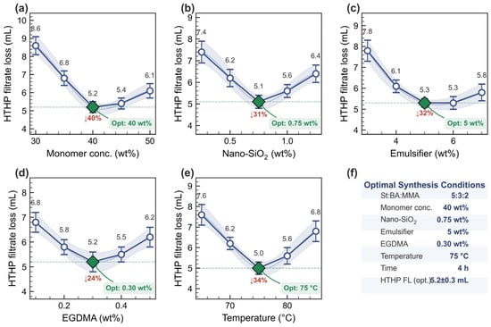
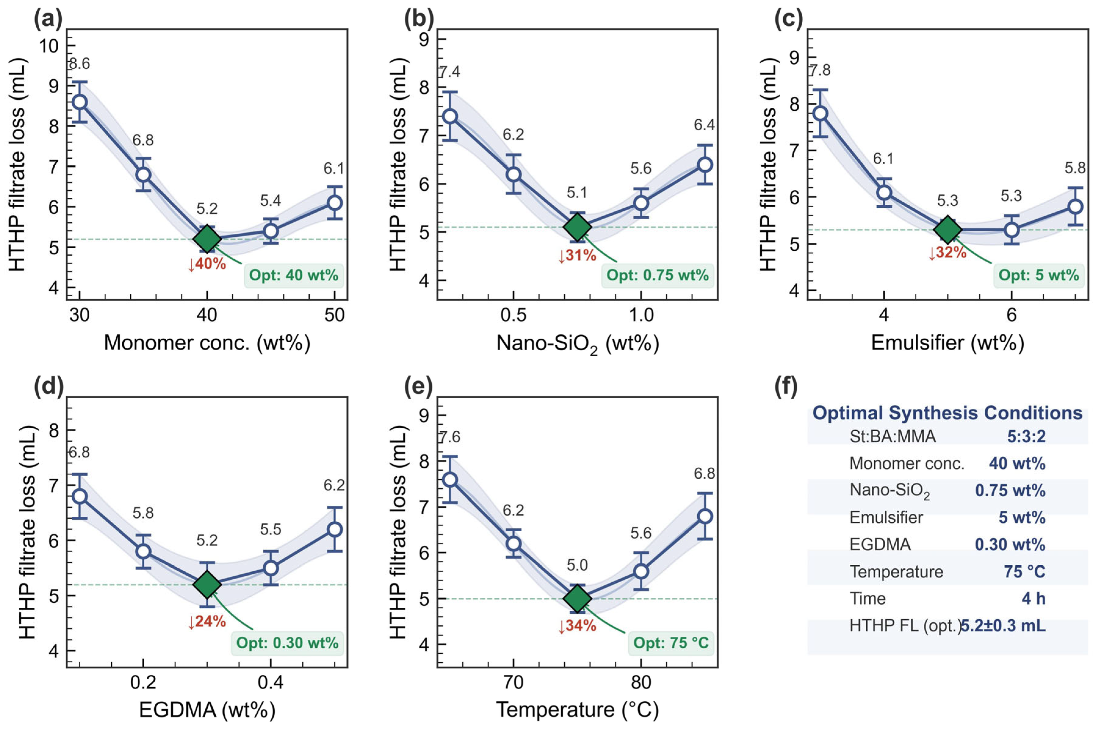
Each factor exhibited a clear optimum (Figure 2): monomer concentration at 40 wt% (filtrate loss 5.2 ± 0.3 mL; higher loading thickened shells, while >40 wt% reduced deformability), nano-SiO2 at 0.75 wt% (5.1 ± 0.3 mL; excess SiO2 promoted aggregation), emulsifier at 5 wt% (5.3 ± 0.2 mL; insufficient emulsifier gave polydisperse particles, excess caused secondary nucleation), EGDMA at 0.30 wt% (5.2 ± 0.4 mL; under-crosslinked particles lacked thermal integrity, over-crosslinked particles lost conformability), and reaction temperature at 75 °C (5.0 ± 0.3 mL; lower temperatures gave incomplete conversion, higher temperatures caused uncontrolled polymerization). The combined conditions yielded a confirmation filtrate loss of 5.2 ± 0.3 mL.
Figure 2.
Effect of synthesis parameters on HTHP filtrate loss: (a) monomer concentration, (b) nano-SiO2 dosage, (c) emulsifier concentration, (d) EGDMA dosage, (e) reaction temperature; (f) summary of selected conditions with confirmation HTHP filtrate loss (5.2 ± 0.3 mL), which serves as the baseline value for all subsequent performance evaluations. Green markers indicate selected values.
The selected conditions are summarized in Table 2. Because each factor was fixed sequentially, they represent a path-dependent local optimum. The narrow effective windows for emulsifier and EGDMA suggest these two parameters most strongly influence plugging performance through their effects on particle size and shell deformability.
Table 2.
Selected synthesis conditions for CSP.
3.2. Chemical Structure and Particle-Size Characterization
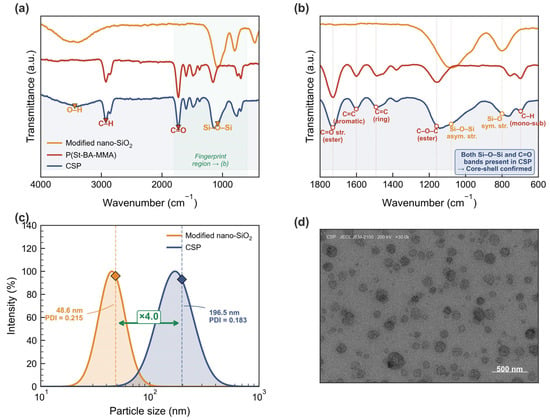
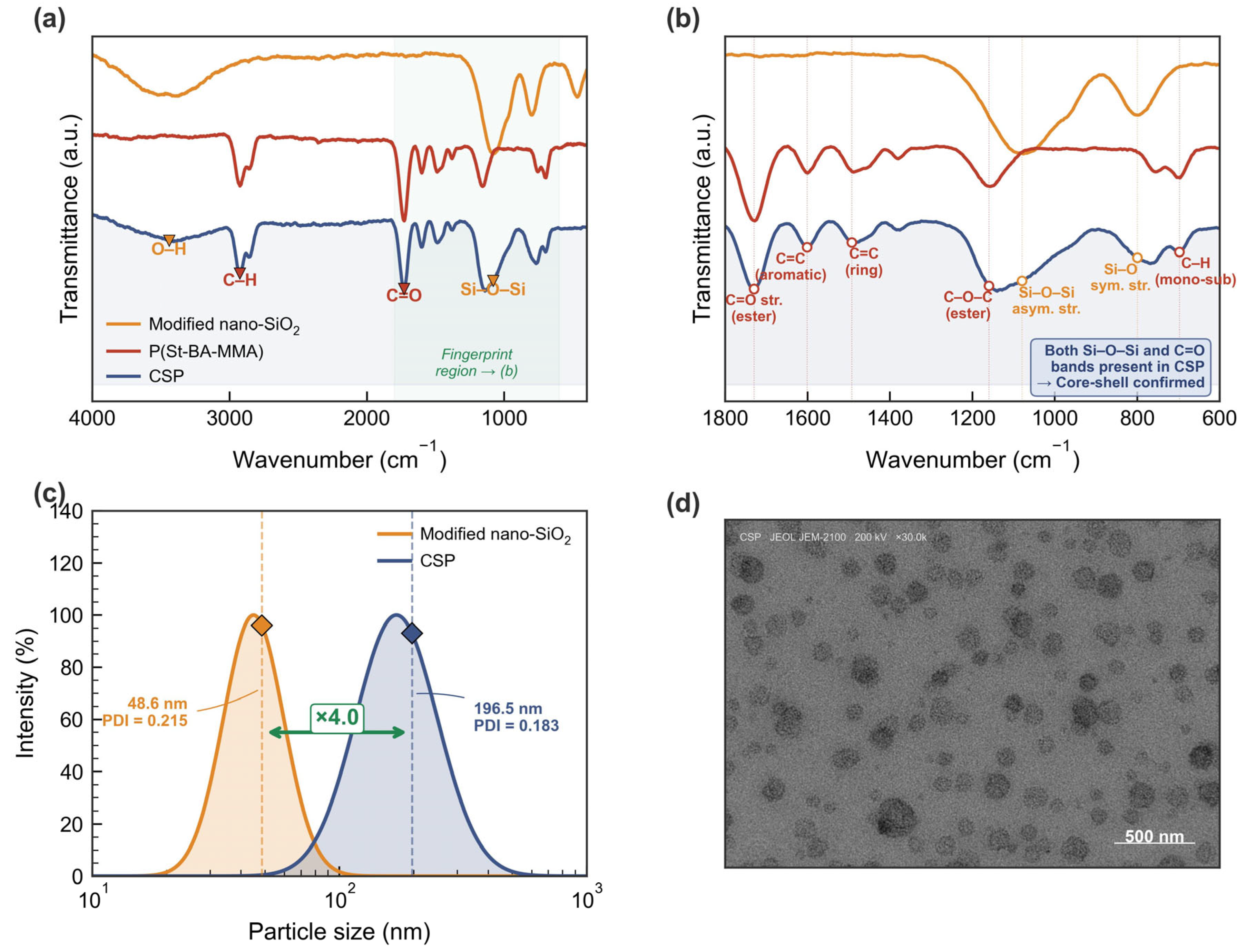
The chemical structure of CSP was verified by FTIR spectroscopy (Figure 3a). The spectrum of modified nano-SiO2 displayed characteristic Si-O-Si asymmetric and symmetric stretching vibrations at 1080 and 800 cm−1, respectively [27], together with a broad O-H band [28] centered at 3440 cm−1. After coating with the polymer shell, the CSP spectrum exhibited additional absorption bands at 2925 and 2850 cm−1 (C-H stretching of the polymer backbone [29]), 1730 cm−1 (C=O stretching from MMA ester groups), 1601 and 1493 cm−1 (aromatic C=C skeletal vibrations from styrene units [30]), and 1160 cm−1 (C-O-C stretching from ester linkages [31]). Notably, the Si-O-Si bands at 1080 and 800 cm−1 persisted in the CSP spectrum, confirming the retention of the SiO2 core within the polymer shell. The expanded fingerprint region (Figure 3b) more clearly resolves the overlap between organic and inorganic absorption bands, confirming the coexistence of both functional group sets and verifying the successful formation of the core–shell structure.
Figure 3.
Structural and size characterization of CSP: (a) FTIR spectra of modified nano-SiO2, P(St–BA–MMA) and CSP over 4000–400 cm−1; (b) expanded fingerprint region (1800–600 cm−1) with peak assignments; (c) DLS particle size distribution with mean diameters, PDI values, and characteristic percentile diameters; (d) TEM micrograph showing spherical CSP particles with core–shell contrast.
DLS measurements (Figure 3c) showed that the unmodified nano-SiO2 had a mean hydrodynamic diameter of 48.6 nm (PDI = 0.215), while CSP exhibited a mean diameter of 196.5 nm with a narrower distribution (PDI = 0.183). The same particle-size analysis yielded median diameters (D50) of 45.2 nm for nano-SiO2 and 189.8 nm for CSP, with 90% of CSP particles falling below 280 nm (D90). The approximately fourfold increase in particle size after polymer coating is consistent with successful shell formation. The low PDI value indicated relatively uniform particles, favoring homogeneous plugging within formation pore networks. The CSP particle size falls within the 50–500 nm range commonly cited as effective for sealing nano-pores in shale formations [32,33,34,35,36], suggesting favorable size-matching for the target application.
The internal structure of CSP was further examined by TEM (Figure 3d). The TEM micrograph revealed predominantly spherical particles with diameters in the 150–250 nm range, consistent with the DLS size distribution (mean 196.5 nm). Several particles displayed a darker central region corresponding to the electron-dense SiO2 core, surrounded by a lighter peripheral zone attributable to the polymer shell, providing visual evidence for the core–shell architecture. The continuous polymer coating observed in TEM indicates effective encapsulation, which is important for maintaining colloidal stability in the oil phase. Taken together, the FTIR spectral evidence, the systematic size increase from DLS, and the TEM visualization of core–shell contrast confirm successful preparation of CSP with the intended nanostructure.
3.3. Colloidal Stability and Interfacial Properties
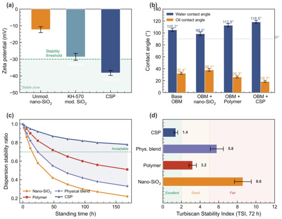
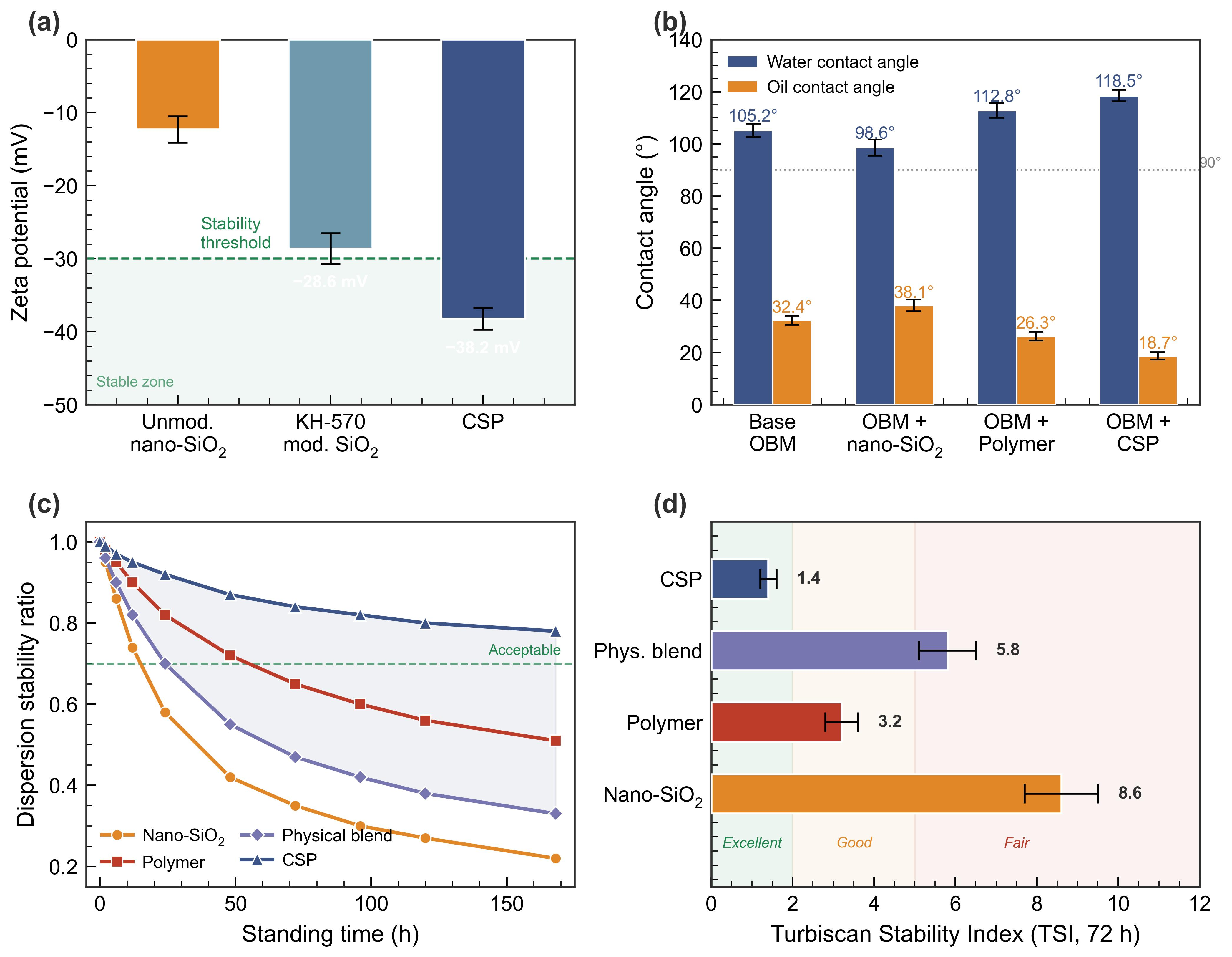
The colloidal stability of CSP in the oil phase was assessed through zeta potential measurements, contact angle analysis, and long-term dispersion monitoring (Figure 4). Because the zeta potential was measured in a low-conductivity non-aqueous medium (white oil, ε ≈ 2), the absolute ζ values are interpreted as relative indicators of dispersion stability within the same medium rather than against aqueous thresholds. Unmodified nano-SiO2 dispersed in white oil exhibited a zeta potential of −12.3 ± 1.1 mV (Figure 4a). Surface modification with KH-570 increased the magnitude to −28.6 ± 1.8 mV, and polymer coating further increased it to −38.2 ± 2.3 mV. The progressive increase in ζ suggests improved colloidal stability, attributable to steric stabilization by the polymer shell and enhanced oil-phase compatibility. The ~26 mV increase from unmodified SiO2 to CSP reflects the cumulative effect of KH-570 grafting (introducing hydrophobic methacrylate moieties) and polymer encapsulation (providing a thick steric barrier), both of which reduce particle–particle attraction in the non-polar medium.
Figure 4.
Colloidal stability characterization: (a) zeta potential in white oil (values serve as relative indicators of dispersion stability in this non-aqueous medium; conventional aqueous thresholds do not strictly apply); (b) water and oil contact angles on shale surfaces; (c) dispersion stability ratio over 168 h; (d) Turbiscan Stability Index at 72 h (72 h was selected as a standardized short-term indicator, whereas stability ratio monitoring continued to 168 h).
Contact angle measurements on shale surfaces (Figure 4b) revealed that the addition of 3 wt% CSP to OBM increased the water contact angle from 105.2 ± 2.1° (base OBM) to 118.5 ± 2.4°, while reducing the oil contact angle from 32.4 ± 1.5° to 18.7 ± 1.2°. For comparison, nano-SiO2 alone yielded a water contact angle of 98.6 ± 2.3° and an oil contact angle of 36.1 ± 1.6°, while the polymer alone produced 112.8 ± 2.2° and 26.3 ± 1.4°, respectively; CSP thus achieved the highest hydrophobicity and oleophilicity among all samples. This enhanced wettability contrast suggests that CSP strengthens the oil–wet character of the treated shale surface, which may favor preferential oil-phase retention in narrow pores and limit water invasion. This shift in wettability is attributed to the adsorption of CSP at the shale surface, where the hydrophobic polymer shell creates a surface layer that resists aqueous phase intrusion.
Because the clay minerals in Longmaxi shale dehydrate and undergo structural alteration above roughly 100 °C, the sessile-drop contact angles were of necessity measured after exposure at 80 °C; direct goniometry at the 180 °C operating temperature is not meaningful on the same substrate, since the measured angle would then reflect thermally altered mineralogy rather than the fluid-induced wettability change. The persistence of the oil–wet conversion under realistic high-temperature conditions is instead supported indirectly by the tests carried out at 180 °C: the sustained HTHP and PPA filtrate control, the 9.2 MPa sand-disk breakthrough pressure, and the 7.8-fold retardation of pressure transmission (Section 3.6.1, Section 3.6.2, Section 3.6.3, Section 3.6.4, Section 3.6.5 and Section 3.6.6) all require a stable oil–wet sealing film at the pore walls and would deteriorate rapidly if the oleophilic layer was thermally desorbed. Mechanistically, at 180 °C, the polymer shell lies well above its Tg (53.6 °C) and is therefore expected to spread and anchor more completely on the shale surface, while the covalently grafted KH-570 coupling layer and the crosslinked shell resist desorption. The long-term robustness of this oleophilic conversion under continuous downhole exposure nevertheless remains to be quantified directly by in situ high-temperature wettability methods, such as high-pressure high-temperature captive-bubble or spontaneous-imbibition measurements, which we identify as a direction for future work.
Long-term dispersion stability was monitored by measuring the dispersion stability ratio over 168 h (Figure 4c). Nano-SiO2 exhibited rapid settling, with the stability ratio declining to 0.22 ± 0.03 at 168 h due to severe aggregation in the oil phase. The physical blend showed intermediate stability (0.33 ± 0.04 at 168 h), indicating that simple mixing does not resolve the incompatibility of inorganic nanoparticles with the oil medium. The pure polymer particles exhibited a stability ratio of 0.52 ± 0.04 at 168 h, better than the inorganic nanoparticles alone but still below the 0.70 threshold (defined in Section 2.5), reflecting limited steric stabilization in the absence of the core–shell architecture. In contrast, CSP maintained a stability ratio of 0.78 ± 0.03 at 168 h, remaining above 0.70 throughout the monitoring period, confirming that the polymer shell effectively screened core–core van der Waals attractions and provided steric stabilization in the non-aqueous medium. The Turbiscan Stability Index (Figure 4d) further supported the superior dispersion stability of CSP (TSI = 1.4 ± 0.2) compared to nano-SiO2 (TSI = 8.6 ± 0.7), the physical blend (TSI = 5.8 ± 0.5), and the pure polymer (TSI = 3.2 ± 0.3). The demonstrated seven-day stability of CSP above the 0.70 threshold under these laboratory conditions satisfies a basic prerequisite for storage and field transport of drilling fluid additives.
3.4. Thermal Stability Analysis
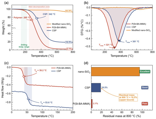
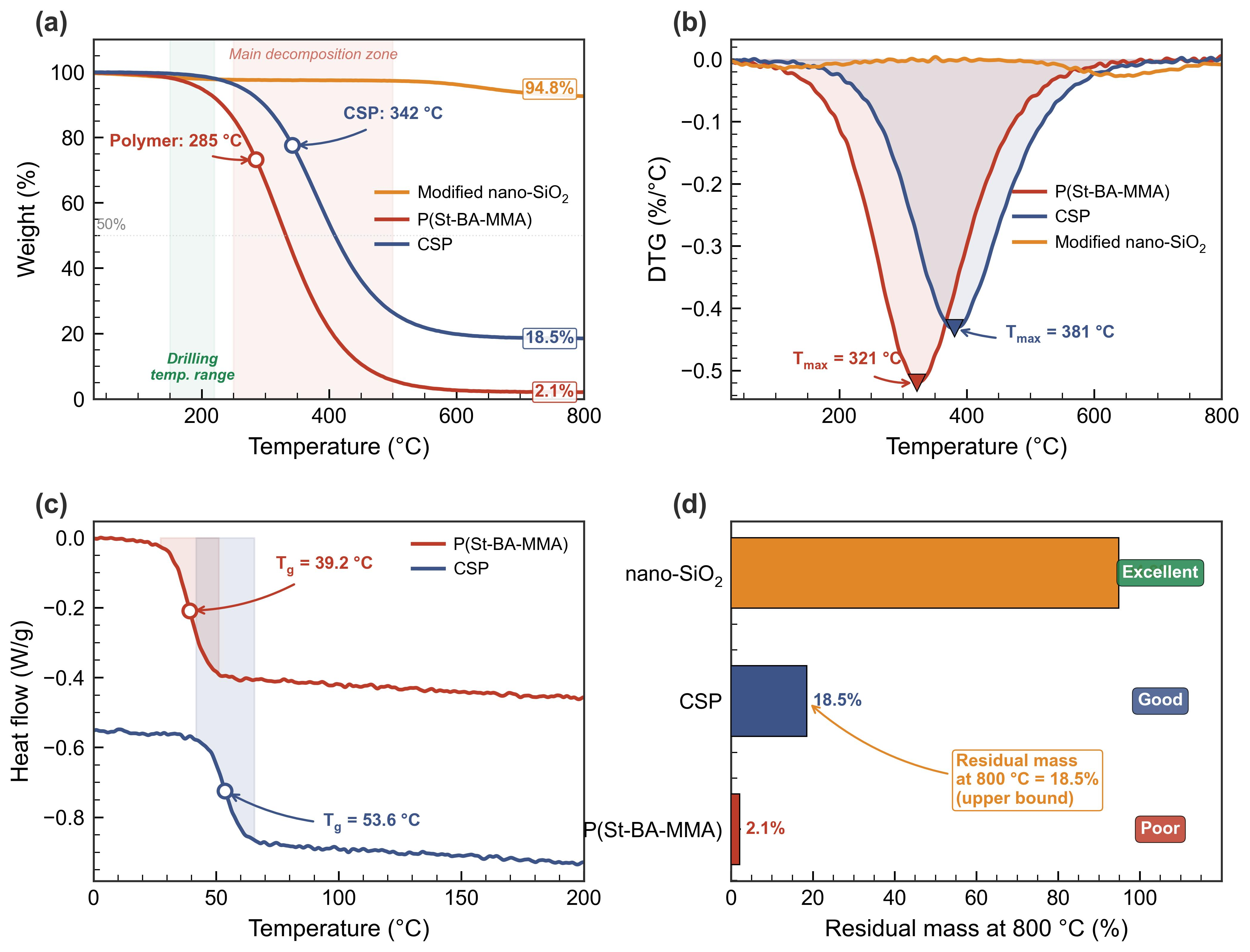
The thermal stability of CSP was evaluated by TGA under nitrogen atmosphere (Figure 5). The pure polymer P(St–BA–MMA) displayed an onset decomposition temperature (determined by the tangent-intersection method on the TGA weight-loss curve) of approximately 285 °C, with 50% weight loss occurring at 362 °C, and only 2.1% residual mass at 800 °C. This thermal profile reflects the limited heat resistance of the purely organic phase.
Figure 5.
Thermal stability analysis: (a) TGA weight-loss curves of P(St–BA–MMA), CSP, and modified nano-SiO2 with decomposition-stage shading; (b) DTG derivative curves with T_max markers; (c) DSC heat-flow curves showing the glass transition region (Tg midpoint: polymer 39.2 °C, CSP 53.6 °C); (d) residual mass at 800 °C with thermal stability grading.
In contrast, CSP exhibited a significantly elevated onset decomposition temperature of 342 °C, representing an increase of 57 °C compared to the pure polymer. The temperature corresponding to 50% weight loss shifted to 418 °C, an improvement of 56 °C. At 800 °C, the residual mass of CSP reached 18.5%, comprising the inorganic SiO2 core together with carbonaceous char from the crosslinked aromatic polymer network, while the modified nano-SiO2 alone retained 94.8% of its mass at 800 °C (the 5.2% loss attributable to combustion of the grafted KH-570 layer). These values confirm that CSP retains sufficient thermal stability for sustained operation at 180 °C, with a safety margin exceeding 160 °C above the target operating temperature. The residual mass bar chart (Figure 5d) provides a direct comparison: CSP retained 18.5% at 800 °C versus only 2.1% for the pure polymer, while modified nano-SiO2 retained 94.8%, clearly illustrating the intermediate thermal character conferred by the core–shell architecture.
The enhanced thermal resistance arises from two complementary effects: the rigid SiO2 core restricts segmental mobility of adjacent polymer chains, and the Si-O-Si network retards release of volatile degradation products. The glass transition behavior of the organic components was characterized by simultaneous DSC (Figure 5c); nano-SiO2 was excluded from DSC analysis because inorganic oxides exhibit no glass transition. The pure polymer P(St–BA–MMA) exhibited a midpoint Tg of 39.2 °C, close to the Fox-equation estimate of 36 °C calculated from the mass fractions and homopolymer Tg values (St, Tg = 373 K; BA, Tg = 219 K; MMA, Tg = 378 K; 1/Tg = 0.5/373 + 0.3/219 + 0.2/378 ≈ 0.00324 K−1). CSP displayed a higher Tg of 53.6 °C, an increase of 14.4 °C attributable to the combined effects of EGDMA crosslinks restricting chain mobility and the rigid SiO2 core confining segmental relaxation of the grafted polymer shell. Since the measured Tg (53.6 °C) is 126 °C below the 180 °C operating temperature, the polymer shell retains ample thermal energy for pressure-induced viscoelastic deformation under downhole conditions.
3.5. Compatibility with Oil-Based Drilling Fluid
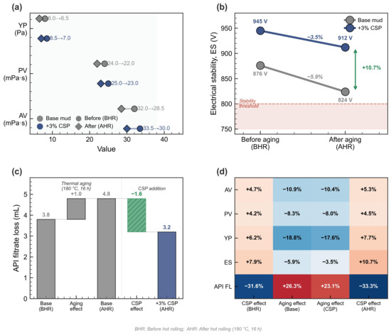
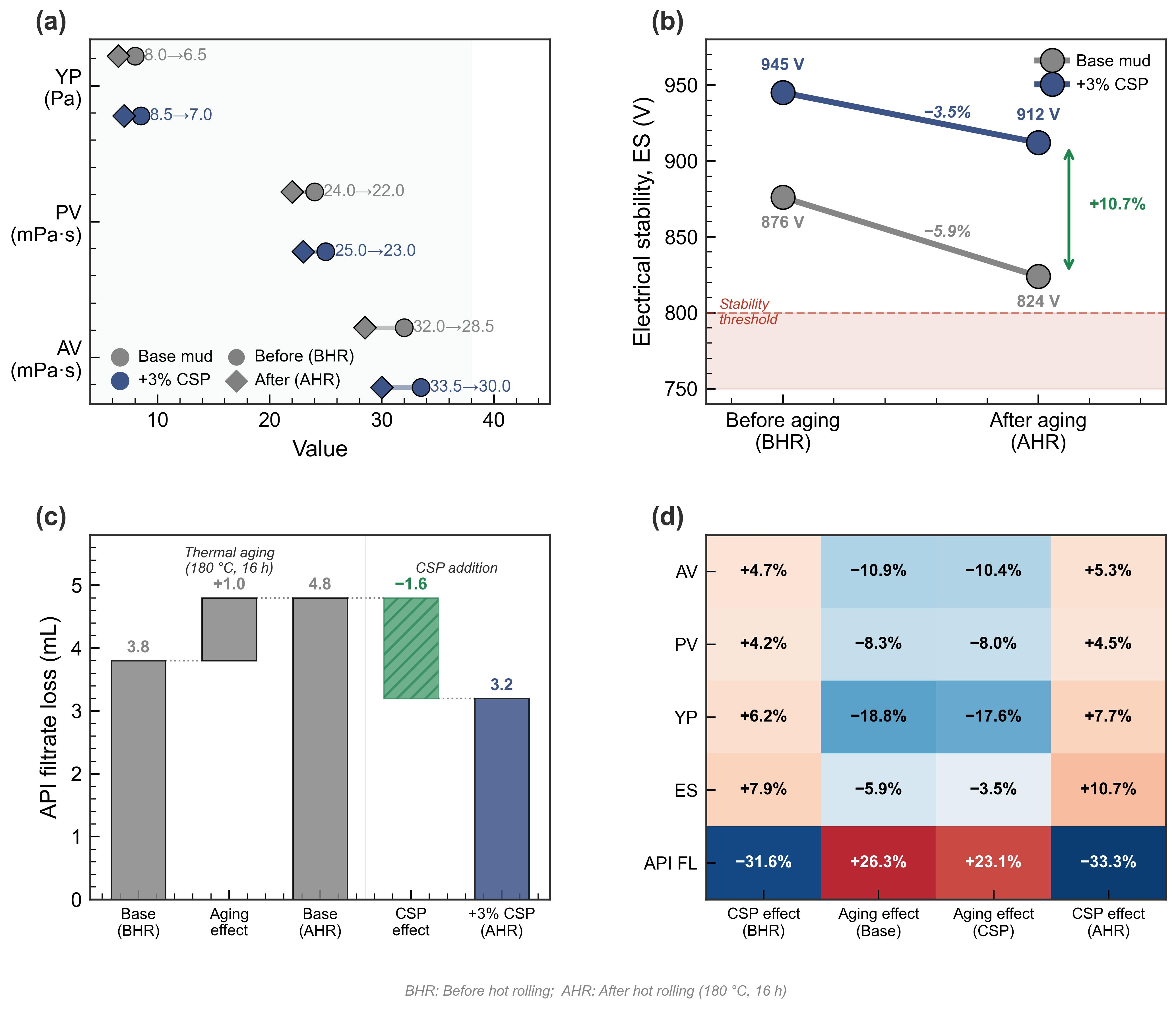
The rheological properties and electrical stability of OBM with and without 3 wt% CSP were measured before and after hot rolling at 180 °C for 16 h (Figure 6).
Figure 6.
Compatibility of CSP with OBM: (a) rheological properties (AV, PV, YP) before and after aging for base mud and CSP-loaded systems; (b) electrical stability (ES) change from BHR to AHR; (c) API filtrate loss from base mud through thermal aging to CSP addition; (d) percentage change matrix across all metrics and conditions. BHR: before hot rolling; AHR: after hot rolling (180 °C, 16 h).
Before aging, the addition of 3 wt% CSP caused only marginal changes in AV, PV, and YP (Table 3), while ES increased from 876 to 945 V, and API filtrate loss decreased from 3.8 to 2.6 mL, reflecting the initial plugging contribution and emulsion-reinforcing effect of CSP.
Table 3.
Rheological and filtration properties of OBM with and without 3 wt% CSP before and after hot rolling at 180 °C for 16 h (n = 3, mean ± SD).
After aging at 180 °C for 16 h, both formulations exhibited slight reductions in viscosity parameters due to partial thermal degradation of the emulsifier. The ES of the base mud decreased from 876 ± 28 to 824 ± 25 V (a 5.9% drop), whereas the CSP-loaded system maintained favorable properties: AV 30.0 ± 1.5 mPa·s, PV 23.0 ± 1.0 mPa·s, YP 7.0 ± 0.5 Pa, ES 912 ± 30 V, and API FL 3.2 ± 0.2 mL. These results confirm that CSP does not adversely affect drilling fluid pumpability or emulsion stability. The percentage change matrix (Figure 6d) shows that all property variations upon CSP addition remained within acceptable ranges. The complete rheological data are presented in Table 3.
Paired t-tests between base mud and +3% CSP groups showed significant differences for ES (p < 0.01) and API FL (p < 0.01) both before and after hot rolling; differences in AV, PV, and YP were not statistically significant (p > 0.05).
The 16 h hot-rolling protocol at 180 °C follows API RP 13B-2 as a standardized accelerated-aging benchmark and is widely used to rank additive durability, but it is shorter than the multi-day to multi-week circulation times of many deep-well operations. Two structural features are expected to favor extended-duration stability: the EGDMA crosslinks lock the shell into a three-dimensional network that resists shear-induced chain scission and flow, and the rigid SiO2 core mechanically reinforces each particle and suppresses coalescence-driven coarsening, while the high onset decomposition temperature (342 °C) leaves a margin of more than 160 °C above the 180 °C service condition. Consistent with this, the rheological and electrical-stability parameters changed only marginally after 16 h of dynamic aging, indicating that the core–shell architecture had not begun to break down. Cumulative effects such as slow hydrolysis of the ester linkages, gradual emulsifier depletion, and fatigue of the polymer network under sustained shear cannot, however, be excluded over longer times and are not captured by a 16 h test. Quantifying the behavior of CSP under prolonged, continuously sheared high-temperature aging—for example 72–168 h dynamic hot-rolling and circulating-loop experiments—is therefore identified as necessary further work (Section 3.8).
3.6. Plugging Performance Evaluation
3.6.1. Effect of CSP Concentration on HTHP Filtrate Loss
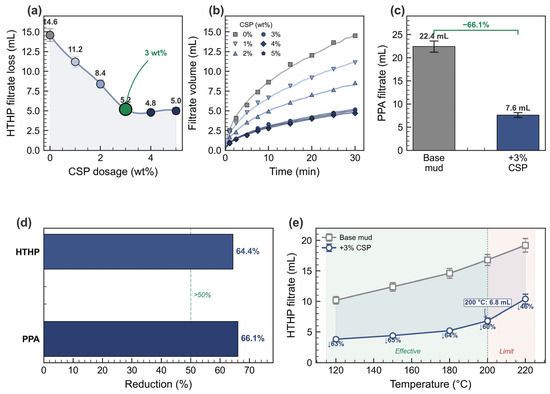
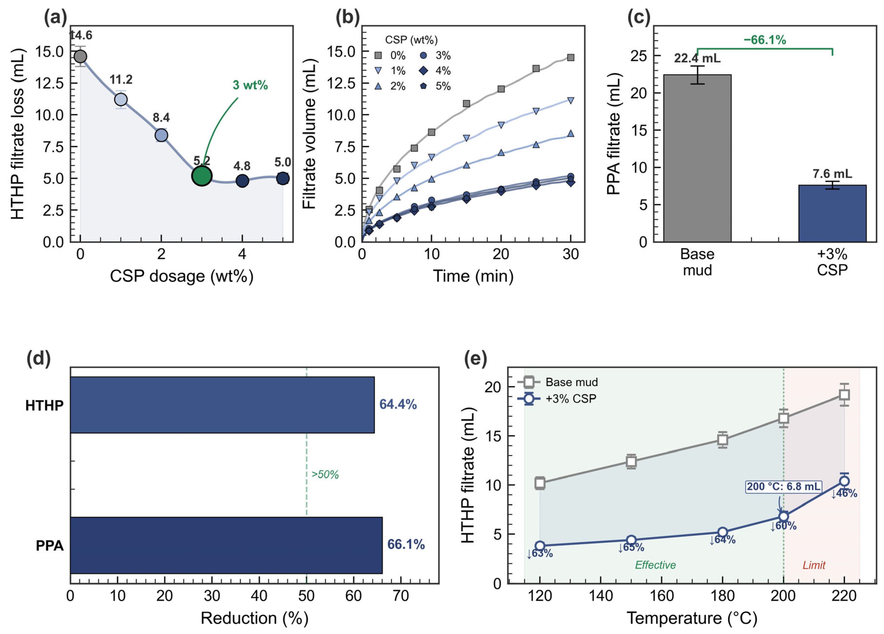
The HTHP filtrate loss of OBM as a function of CSP concentration after aging at 180 °C for 16 h is presented in Figure 7a. The base mud without CSP exhibited an HTHP filtrate loss of 14.6 ± 0.8 mL. Progressive addition of CSP from 1 to 3 wt% caused a monotonic decrease in filtrate loss from 11.2 ± 0.7 to 5.2 ± 0.3 mL, corresponding to reductions of 23.3% and 64.4%, respectively. At 3 wt%, the plugging agent concentration reached a critical threshold at which sufficient particles were available to form a complete, multi-layered sealing structure across the filter medium pore network. The filtrate volume curves (Figure 7b) further illustrate that the CSP-treated systems reached steady-state filtration within the first 10 min, whereas the base mud continued to produce filtrate at a nearly constant rate throughout the 30 min test period, indicating incomplete filter-cake formation.
Figure 7.
Plugging performance evaluation: (a) HTHP filtrate loss as a function of CSP concentration; (b) filtrate volume versus time at different CSP concentrations; (c) PPA filtrate loss comparison between base mud and CSP; (d) HTHP and PPA filtrate loss reduction rates; (e) HTHP filtrate loss versus temperature from 120 to 220 °C with effective range shading.
Further increasing the CSP dosage to 4 and 5 wt% yielded filtrate losses of 4.8 ± 0.3 and 5.0 ± 0.4 mL. One-way ANOVA indicated no significant difference among the 3, 4, and 5 wt% groups (p = 0.38), confirming a performance plateau. Based on these results, 3 wt% was selected for subsequent evaluations.
3.6.2. PPA Filtrate Loss
PPA tests employing a 20 μm ceramic disk provided a more stringent evaluation of plugging performance. Under identical conditions (180 °C, 3.5 MPa), the base mud produced a PPA filtrate loss of 22.4 ± 1.2 mL, while 3 wt% CSP reduced the PPA filtrate loss to 7.6 ± 0.5 mL, a 66.1% reduction (Figure 7c). The PPA and HTHP reduction rates were comparable (66.1% and 64.4%, respectively; Figure 7d), with the 1.7 percentage-point difference falling within experimental uncertainty for triplicate measurements, indicating that CSP provides consistent plugging performance across both filter media.
3.6.3. Temperature Resistance
The thermal endurance of CSP was assessed by measuring HTHP filtrate loss across a temperature range of 120 to 220 °C at a fixed differential pressure of 3.5 MPa (Figure 7e). For the base mud, the filtrate loss increased steadily from 10.2 mL at 120 °C to 19.2 mL at 220 °C, reflecting the progressive thermal degradation of organic fluid loss control additives.
With 3 wt% CSP, the filtrate loss remained below 5.2 mL from 120 to 180 °C and increased moderately to 6.8 mL at 200 °C. At 220 °C, the filtrate loss rose sharply to 10.4 mL, indicating structural degradation of the polymer shell. The effective temperature validated by the complete evaluation suite (HTHP, PPA, sand disk, core displacement, and pressure transmission) is 180 °C. At 200 °C, the HTHP filtrate loss of 6.8 ± 0.5 mL still represents a ~60% reduction relative to the base mud (16.8 ± 0.9 mL), suggesting potential for higher-temperature applications that warrant further validation with the full test suite.
3.6.4. Comparative Performance Analysis
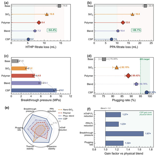
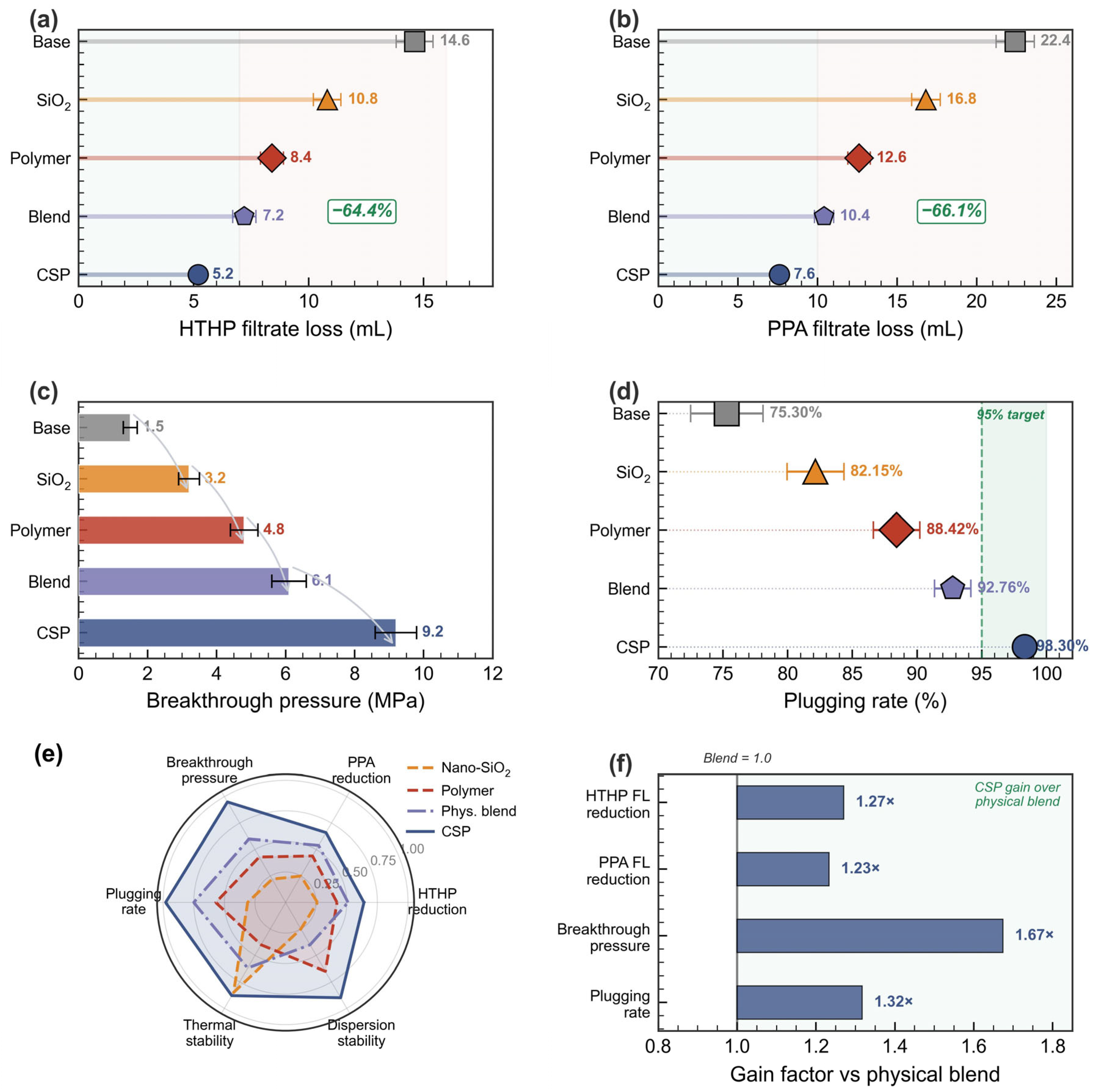
To demonstrate the advantage of the core–shell architecture, CSP was compared against nano-SiO2 alone, polymer P(St–BA–MMA) alone, and a physical blend of the two, all at 3 wt% under identical conditions (180 °C, 3.5 MPa, 16 h aging). Figure 8a–d present the comparison across four key metrics, while Figure 8e,f provide normalized visual summaries.
Figure 8.
Comparative plugging performance of base OBM, nano-SiO2, polymer, physical blend, and CSP: (a) HTHP filtrate loss; (b) PPA filtrate loss; (c) breakthrough pressure; (d) plugging rate with 95% threshold; (e) normalized multi-dimensional radar comparison; (f) gain factors of CSP relative to the physical blend.
For HTHP filtrate loss (Figure 8a), nano-SiO2 alone achieved only a 26.0% reduction (10.8 ± 0.6 mL), limited by its rigid morphology and poor pore-filling capacity. The polymer alone performed better (42.5% reduction, 8.4 ± 0.5 mL) owing to its deformability, but insufficient thermal stability led to partial degradation during aging. The physical blend yielded a 50.7% reduction (7.2 ± 0.5 mL), indicating that combining rigid and soft particles improves sealing even without a formal core–shell architecture, likely through a rudimentary graded-particle packing effect. CSP achieved the highest reduction of 64.4% (5.2 ± 0.3 mL), significantly outperforming all alternatives. PPA tests (Figure 8b) followed the same trend, with CSP achieving a 66.1% reduction compared to 25.0% for nano-SiO2 and 43.8% for the polymer.
Breakthrough pressure (Figure 8c) provided the most pronounced differentiation: CSP supported 9.2 ± 0.6 MPa, more than 2.9 times that of the polymer alone (4.8 ± 0.4 MPa) and 1.5 times that of the physical blend (6.1 ± 0.5 MPa). This large gap in mechanical strength strongly identifies the rigid SiO2 core as the structural backbone of the plugging layer: without covalent integration, the physical blend cannot develop an equally load-bearing skeleton. The plugging rate (Figure 8d) reached 98.30 ± 0.4% for CSP, the only formulation exceeding 95% in the present test set.
The radar chart (Figure 8e) and gain factor chart (Figure 8f) provide normalized overviews of the multi-dimensional performance advantage of CSP. One-way ANOVA with Tukey’s HSD post hoc test confirmed that CSP significantly outperformed each control sample for all four metrics (p < 0.01 for HTHP FL, PPA FL, breakthrough pressure, and plugging rate; p < 0.05 for CSP vs. physical blend in HTHP FL).
To place these results in the context of recent literature, Table 4 compares CSP with representative high-temperature plugging and wellbore-stabilization systems reported between 2023 and 2026. Several points emerge. First, CSP operates at 180 °C, with HTHP data extending to 200 °C, matching or exceeding the highest service temperatures reported for the comparison systems. Second, the HTHP and PPA filtrate-loss reductions achieved by CSP (64.4% and 66.1%) are larger than those reported for the recent micro-nano and mesoporous-silica agents, which typically fall in the ~32–50% range on comparable media. Third, and most importantly, CSP is characterized across a broader set of sealing metrics than most prior studies: whereas the majority of comparable works quantify performance mainly through filtrate-loss or membrane-plugging tests, the present work additionally reports a sand-disk breakthrough pressure (9.2 MPa), a core-displacement plugging rate (98.3%), and a quantitative pressure transmission inhibition on natural shale (a 7.8-fold extension of the 50% equalization time). The covalent coupling of a rigid SiO2 core with a Tg-tunable terpolymer shell is the structural origin of this combined load-bearing and pore-filling capability, which single-component or physically blended systems do not provide. In Table 4, NR denotes a metric not reported in the cited study rather than an absence of capability.
Table 4.
Comparison of CSP with representative recently reported (2023–2026) plugging and wellbore-stabilization agents. NR = not reported in the cited study.
Examined metric by metric, this comparison underscores the breadth of the present evaluation. (1) Temperature resistance: CSP is validated at 180 °C, with HTHP data extending to 200 °C and an onset decomposition temperature of 342 °C, matching the highest service temperatures among the comparison systems (e.g., 180 °C for Li et al. [23] and Qin et al. [32]) while, unlike most of them, providing an explicit thermal-decomposition margin. (2) HTHP/PPA filtrate-loss reduction: the 64.4% HTHP and 66.1% PPA reductions exceed the ~32–48% reductions reported for the recent micro-nano and mesoporous-silica agents on comparable media [9,23]. (3) Breakthrough pressure and (4) plugging rate: whereas the cited works largely do not report these load-bearing metrics (NR), CSP delivers a 9.2 MPa sand-disk breakthrough pressure and a 98.3% core-displacement plugging rate. (5) Pressure transmission inhibition: the 7.8-fold extension of the 50% pressure-equalization time on natural shale quantified here is a dimension that, to our knowledge, none of the compared studies reports. CSP is therefore among the few reported systems characterized across all five sealing dimensions simultaneously, which is the principal evidence for the novelty and practical effectiveness of the proposed core–shell approach.
3.6.5. Sand-Disk Plugging and Core Displacement
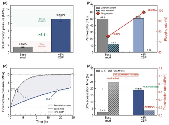
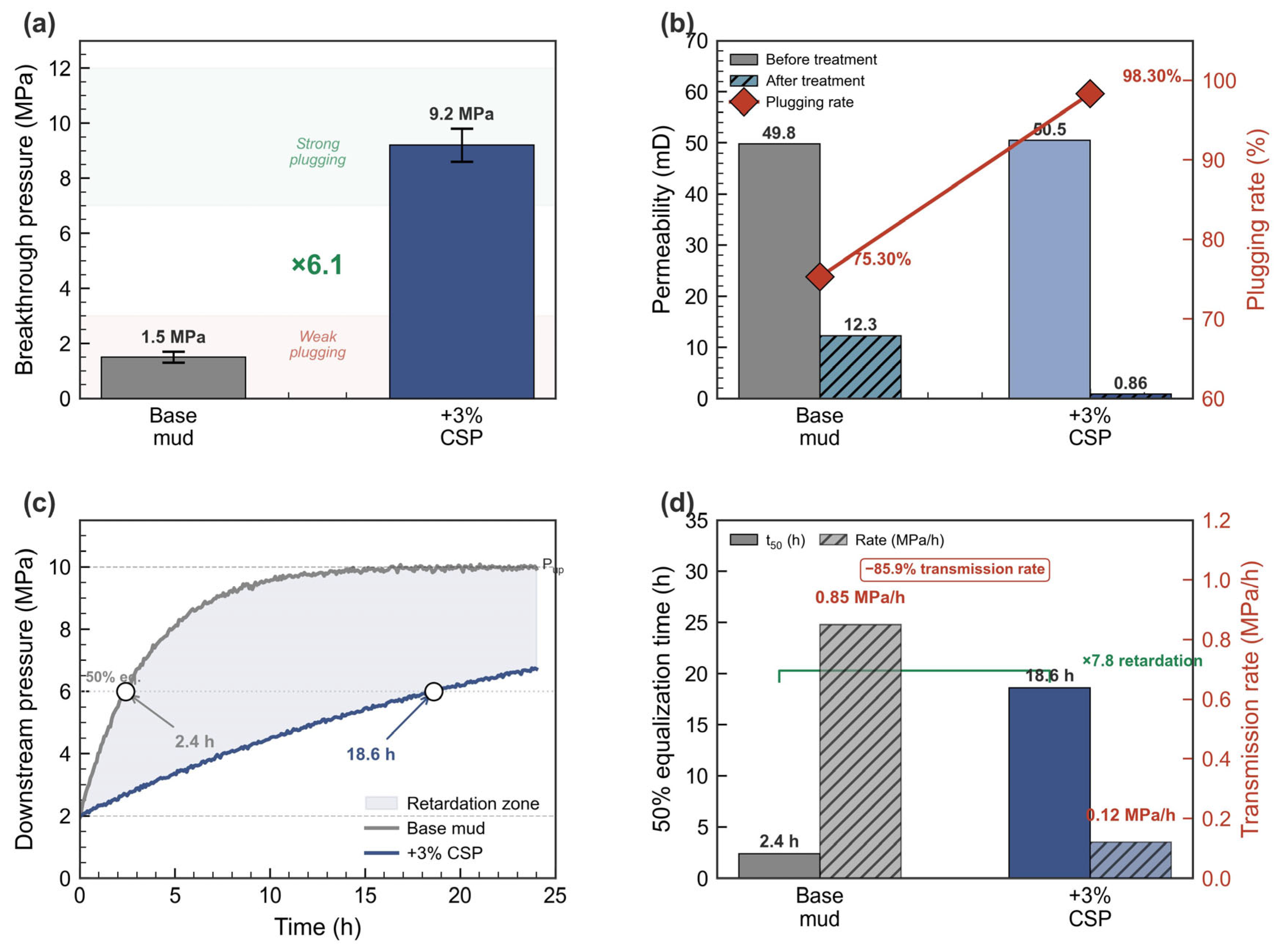
Sand-disk plugging tests evaluated the pressure-bearing capacity of the CSP plugging layer. The sand disk and artificial sandstone cores (~50 mD) used in this section have substantially higher permeability than typical deep shale formations (10−3 to 10−1 mD); these tests therefore demonstrate the sealing capacity of CSP under controlled conditions, while the pressure transmission tests on natural shale cores (Section 3.6.6) provide more directly relevant evidence for shale applications. On a 20 μm sintered sand disk at 180 °C, the base mud supported a breakthrough pressure of only 1.5 ± 0.2 MPa (Figure 9a). With 3 wt% CSP, the breakthrough pressure increased to 9.2 ± 0.6 MPa (6.1-fold increase), indicating formation of a mechanically robust sealing layer capable of withstanding substantial differential pressures that would be encountered during drilling operations in deep shale formations.
Figure 9.
Sand disk and core displacement evaluation: (a) breakthrough pressure comparison; (b) core permeability before and after treatment with plugging rate overlay; (c) continuously recorded downstream pressure evolution during pressure transmission tests (1 min acquisition intervals); (d) 50% equalization time and pressure transmission rate comparison.
Core displacement experiments on artificial sandstone cores (initial permeability ~50 mD) provided quantitative assessment of plugging efficiency (Figure 9b). After treatment with the base mud alone, the core permeability decreased from 49.8 ± 1.6 to 12.3 ± 1.0 mD, yielding a plugging rate of 75.30 ± 2.8%. Treatment with OBM containing 3 wt% CSP reduced the core permeability from 50.5 ± 1.8 to 0.86 ± 0.12 mD, achieving a plugging rate of 98.30 ± 0.4%. Against the already elevated baseline of the base mud (75.30%), CSP reduced the residual permeability by 93.0% (from 12.3 to 0.86 mD), demonstrating effective sealing of the remaining interconnected pore pathways. The residual permeability of 0.86 mD indicates that nearly all effective flow channels within the core were blocked by the CSP plugging layer, consistent with the formation of a dense, multi-layered seal rather than a superficial surface deposit.
3.6.6. Pressure Transmission Test
Pressure transmission experiments (n = 3 matched pairs) on natural Longmaxi formation shale cores (Sichuan Basin, China; diameter 25 mm, length 10 mm; matrix permeability 0.05–0.12 mD; porosity 3.8–5.2%; bedding perpendicular to flow) evaluated the ability of CSP to inhibit fluid pressure propagation (Figure 9c,d). Cores were paired such that the initial permeability differed by no more than ±15% within each pair; although the overall permeability range spans approximately one order of magnitude, each matched pair exhibited comparable permeability, ensuring that within-pair comparisons were valid. When exposed to base mud at 180 °C, the shale core exhibited a pressure transmission rate of 0.85 ± 0.08 MPa/h, reaching 50% pressure equalization within 2.4 ± 0.3 h. The rapid equalization for the base mud indicates that the inherent filtration performance of the OBM alone is insufficient to resist pressure propagation through the shale matrix.
With 3 wt% CSP, the pressure transmission rate dropped to 0.12 ± 0.02 MPa/h, and the time to 50% equalization extended to 18.6 ± 1.5 h—approximately 7.8 times longer than the base mud. This pronounced retardation indicates that CSP markedly restricted the effective flow pathways through the shale matrix, which is expected to preserve near-wellbore mechanical strength and enhance wellbore stability. From an engineering perspective, extending the equalization time from 2.4 to 18.6 h could provide a wider operational window for drilling and casing operations before pore pressure buildup compromises the mechanical stability of the borehole wall.
3.7. Proposed Plugging Mechanism
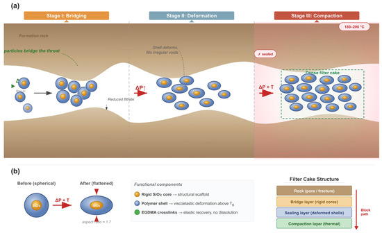
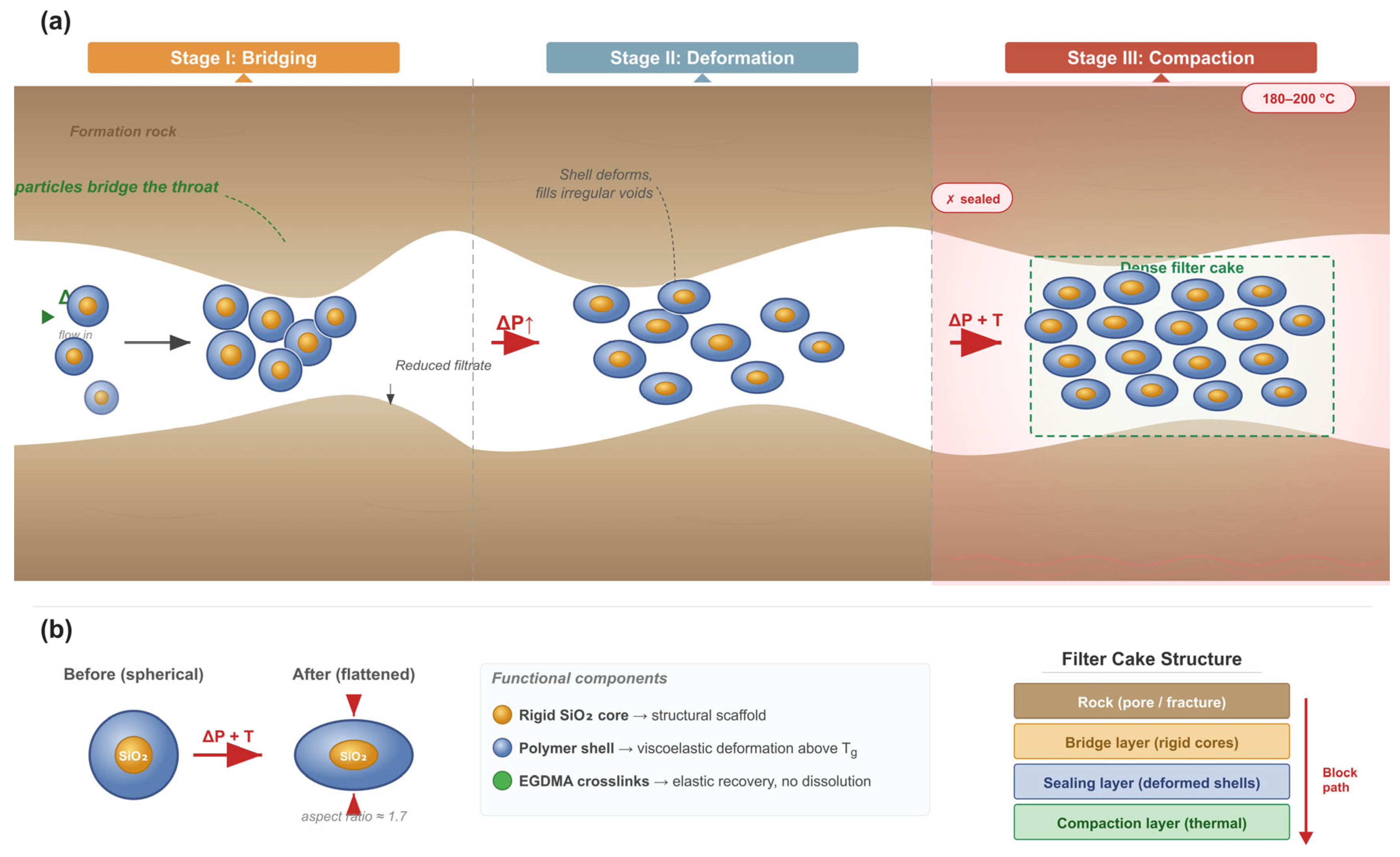
Based on macroscopic filter-cake measurements and the material properties characterized in Section 3.2, Section 3.3 and Section 3.4, a three-stage plugging mechanism is proposed (Figure 10 and Figure 11). This mechanism is inferred from macroscopic performance data, particle-level characterization (TEM, DLS, TGA-DSC), and filter-cake thickness measurements.
Figure 10.
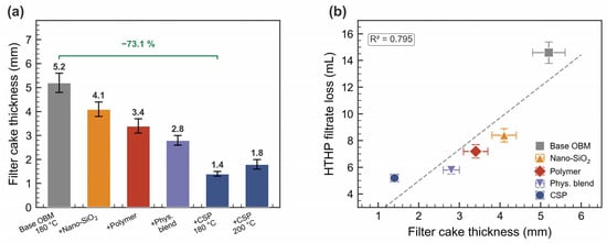
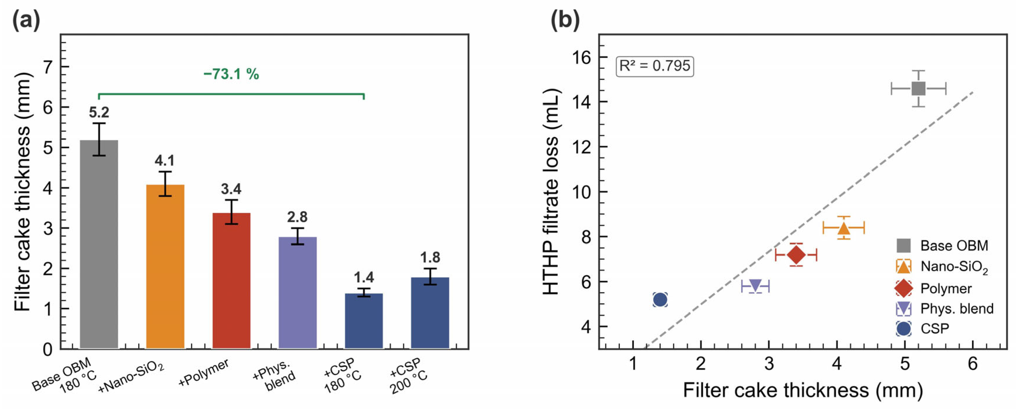
Filter-cake thickness analysis: (a) cake thickness under different conditions and formulations; (b) cake thickness versus HTHP filtrate loss correlation across all sample types.
Figure 11.
Hypothesized plugging mechanism of CSP: (a) three-stage sealing process (bridging → deformation → thermal compaction) in a microfracture under combined pressure and temperature; (b) single-particle deformation model and the resulting layered filter-cake structure. The depicted stages are inferred from macroscopic evidence and may overlap rather than proceed strictly sequentially.
In Stage I (bridging), CSP particles are transported toward the formation face by the pressure differential; the rigid SiO2 cores are hypothesized to lodge at pore throat constrictions, forming initial bridge structures, while the polymer shell promotes adhesion to pore walls. The TEM-confirmed core–shell architecture (Figure 3d) and the DLS particle size (196.5 nm, within the 50–500 nm shale pore range) provide the structural basis for this bridging function. In Stage II (deformation filling), continued pressure forces additional CSP particles into the partially bridged network. The DSC-measured Tg of 53.6 °C (Section 3.4) confirms that the polymer shell is well above its glass transition at the 180 °C test temperature, with a temperature gap of 126 °C that qualitatively indicates the shell is in a rubbery state amenable to pressure-induced deformation; the actual extent of deformation also depends on applied pressure, contact time, and crosslink density. The markedly thinner filter cakes formed by CSP (1.4 mm vs. 5.2 mm for base OBM, a 73.1% reduction; Figure 10a) provide indirect evidence of deformation-assisted densification: the same filtrate reduction achieved with a much thinner cake implies denser particle packing. In Stage III (thermal compaction), prolonged exposure to formation temperatures (≥150 °C) is proposed to promote further coalescence of polymer shells into a dense layer reinforced by discrete SiO2 nanoparticles that prevent complete collapse.
Filter-cake thickness measurements provided quantitative support for the proposed mechanism (Figure 10). The CSP filter cake at 180 °C was only 1.4 mm thick, compared to 5.2 mm for the base OBM (Figure 10a). At 200 °C, the CSP cake thickness increased slightly to 1.8 mm but remained substantially thinner. The progressive thinning from base OBM (5.2 mm) through nano-SiO2 (4.1 mm), polymer (3.4 mm), and physical blend (2.8 mm) to CSP (1.4 mm) mirrors the overall plugging performance trend observed across all test metrics (Figure 10b), strongly suggesting that the core–shell architecture enables the most efficient packing of the filter-cake structure.
The overall mechanism is illustrated schematically in Figure 11.
This three-stage mechanism provides a plausible explanation for the superior plugging performance of CSP over single-component agents. The inorganic core provides thermal stability and mechanical strength for bridging, while the polymer shell enables deformation and densification—two functions that cannot be achieved simultaneously by either component alone.
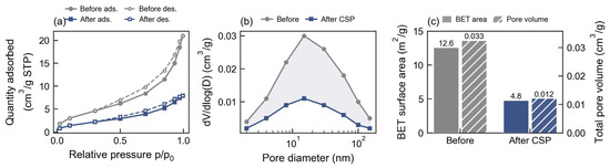
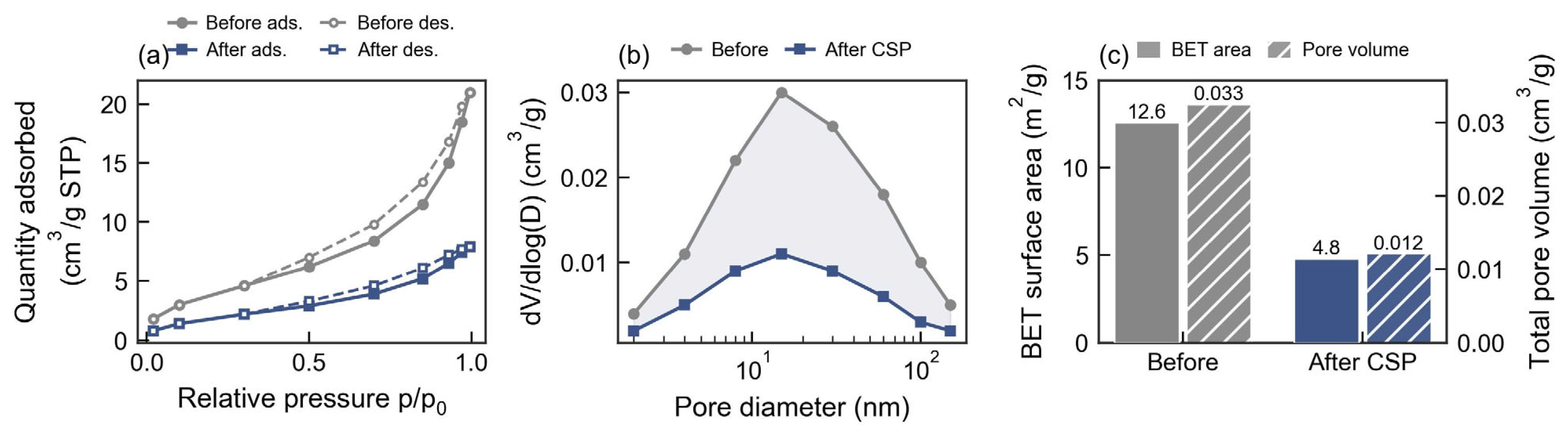
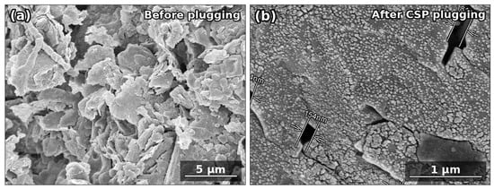
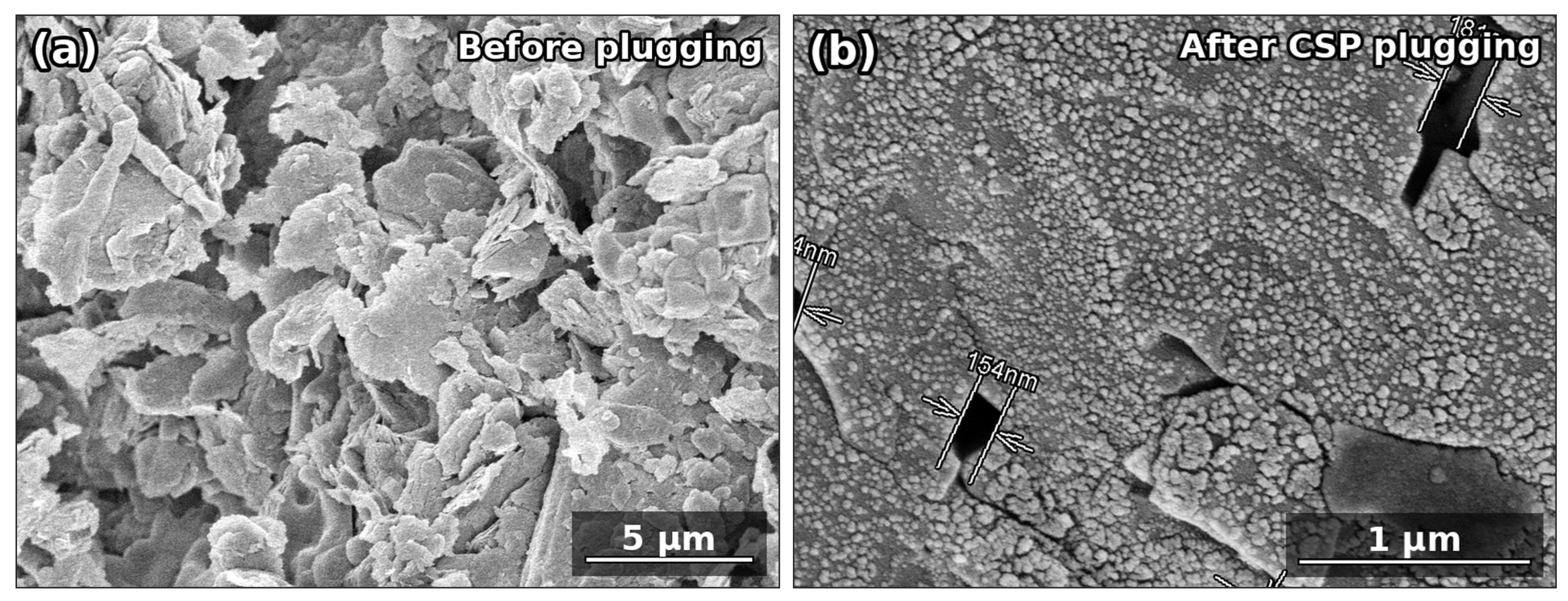
Direct quantitative evidence for pore occlusion is provided by low-temperature N2 physisorption analysis of the Longmaxi shale before and after CSP plugging (Figure 12). The N2 adsorption–desorption isotherms (Figure 12a) retained a type-IV character with a clear hysteresis loop at medium-to-high relative pressures, indicating slit-like mesopores and inter-particle pore spaces in the shale matrix. After CSP treatment, both the adsorption and desorption branches shifted markedly downward, showing that a substantial fraction of the originally accessible nano- and mesopore volume became blocked. The BJH pore-size distribution (Figure 12b) showed attenuation across the 8–150 nm interval, with the most pronounced reduction concentrated in the 15–60 nm mesopore range; the dominant BJH peak at 15 nm decreased from 0.030 to 0.011 cm3/g, a 63.3% reduction. Quantitatively, the BET specific surface area decreased from 12.6 to 4.8 m2/g and the total pore volume from 0.0325 to 0.0121 cm3/g, corresponding to reductions of 61.9% and 62.8%, respectively (Figure 12c). This before/after comparison supplies direct quantitative pore-structure evidence that CSP blocks accessible shale nano- and mesopores, supporting the bridging–deformation–compaction mechanism inferred from the macroscopic plugging tests. Pores larger than the ~200 nm upper limit of the N2 method are addressed by the sand-disk breakthrough-pressure and core-displacement results, while the existing TEM micrograph (Figure 3d) independently confirms the core–shell particle morphology. Direct microscopic confirmation of pore sealing is further provided by scanning electron microscopy (SEM) of the Longmaxi shale surface before and after CSP treatment (Figure 13), which visualizes the conversion of the open, porous shale matrix into a dense, compacted filter cake with the nano- and micro-pores largely occluded. Direct SEM imaging of the deformed particles and the sealed pore network was not available in this study; the proposed mechanism is therefore grounded in the convergence of microscopic (SEM), quantitative (N2 adsorption), particle-level (TEM), and macroscopic (filter-cake thickness, breakthrough pressure, and pressure transmission) evidence, and SEM visualization is identified as a valuable addition for future work.
Figure 12.
Quantitative pore-structure evidence of CSP plugging by low-temperature N2 adsorption: (a) N2 adsorption–desorption isotherms of the Longmaxi shale before and after CSP plugging (solid: adsorption; dashed/open symbols: desorption); (b) BJH pore-size distribution before and after plugging; (c) BET specific surface area and total pore volume before vs. after plugging.
Figure 13.
Field-emission SEM images of the Longmaxi shale surface: (a) before plugging, showing the open, porous, platelet-stacked matrix with abundant inter-particle pores and microfractures; (b) after plugging with 3 wt% CSP, showing a dense, compacted filter cake in which coalesced polymer shells and embedded SiO2 nanoparticles occlude the pore network, leaving only sparse residual sub-micron pores. Scale bars: (a) 5 µm; (b) 1 µm.
Direct microscopic evidence of pore sealing is shown in Figure 13, which compares the surface morphology of the Longmaxi shale before and after CSP plugging. The untreated shale (Figure 13a) exhibits a typical open, layered texture in which clay platelets and mineral grains are loosely stacked, leaving abundant interconnected microfractures and inter-particle pores that serve as ready pathways for filtrate invasion and pressure transmission. After treatment with 3 wt% CSP (Figure 13b), the same surface is covered by a continuous, densely packed sealing layer: deformed polymer shells have coalesced into a compact film within which the rigid SiO2 cores remain discernible as embedded nanoscale granules, and only a few sub-micron residual pores persist. This morphological transition—from an open, porous network to a compacted, pore-occluded filter cake—provides direct visual confirmation of the bridging–deformation–compaction sequence inferred from the macroscopic tests and is fully consistent with the ~62% reductions in BET surface area and total pore volume measured by N2 physisorption. The simultaneous presence of a continuous deformed polymer phase and discrete embedded SiO2 particles in Figure 13b also corroborates the proposed complementary roles of the deformable shell (pore filling and densification) and the rigid core (mechanical reinforcement that prevents complete collapse of the seal under differential pressure).
3.8. Limitations and Future Work
Several limitations should be acknowledged. (1) The comprehensive plugging evaluation suite was completed at 180 °C; performance at 200 °C is supported only by preliminary HTHP data. (2) The artificial sandstone cores (~50 mD) have substantially higher permeability than deep shale formations; the pressure transmission tests on natural shale cores partially address this gap. (3) The sequential single-factor optimization identifies a path-dependent optimum; response surface methodology may reveal parameter interactions that further improve performance. Future work will extend the full evaluation to higher temperatures and investigate the long-term stability of CSP under continuous drilling circulation conditions.
4. Conclusions
A core–shell nano-plugging agent (CSP) comprising KH-570-modified nano-SiO2 as the core and P(St-BA-MMA) as the shell was synthesized via emulsion polymerization and systematically evaluated for oil-based drilling fluids. CSP particles had a mean diameter of 196.5 nm (PDI = 0.183), an onset decomposition temperature of 342 °C, and maintained colloidal stability in the oil phase over 168 h. At 3 wt%, CSP reduced HTHP filtrate loss by more than 64% and PPA filtrate loss by more than 66%, while increasing the sand-disk breakthrough pressure from 1.5 to 9.2 MPa. Core displacement and pressure transmission tests confirmed effective sealing, with a plugging rate exceeding 98% on sandstone cores and a 7.8-fold extension of the pressure equalization time on natural shale cores. The integrated core–shell architecture consistently outperformed nano-SiO2 alone, polymer alone, and their physical blend across all evaluated metrics. Filter-cake thickness measurements are consistent with a proposed three-stage plugging mechanism—bridging, deformation filling, and thermal compaction—driven by the complementary roles of the rigid SiO2 core and the deformable terpolymer shell. Low-temperature N2 adsorption provided direct quantitative evidence for the sealing mechanism, showing that CSP reduced the BET surface area of the treated shale from 12.6 to 4.8 m2/g (61.9%) and the total pore volume from 0.0325 to 0.0121 cm3/g (62.8%), with the 8–150 nm pore population strongly attenuated. Scanning electron microscopy of the shale surface gave concordant direct visual evidence, revealing the transformation of the open, porous, platelet-stacked matrix into a dense, compacted filter cake with the pore network largely occluded. Although these findings were obtained under laboratory conditions, they indicate that CSP merits further evaluation as a high-temperature plugging agent for wellbore stabilization in deep shale formations.
Author Contributions
B.Z.: Investigation, Methodology, Writing—original draft; W.H.: Conceptualization, Investigation, Writing—review and editing; J.L.: Investigation, Methodology, Writing—review and editing. All authors have read and agreed to the published version of the manuscript.
Funding
No funding was received for this study.
Data Availability Statement
The original contributions presented in this study are included in the article. Further inquiries can be directed to the corresponding author.
Conflicts of Interest
Authors Bo Zhao and Junyi Liu were employed by Sinopec Shengli Oilfield Service Corporation. The remaining author declares that the research was conducted in the absence of any commercial or financial relationships that could be construed as a potential conflict of interest. The Sinopec Shengli Oilfield Service Corporation had no role in the design of the study; in the collection, analyses, or interpretation of data; in the writing of the manuscript, or in the decision to publish the results.
References
- Wang, H.; Huang, H.; Bi, W.; Ji, G.; Zhou, B.; Zhuo, L. Deep and ultra-deep oil and gas well drilling technologies: Progress and prospect. Nat. Gas Ind. B 2022, 9, 141–157. [Google Scholar] [CrossRef] [Scilit]
- Sun, J.; Yang, J.; Bai, Y.; Lyu, K.; Liu, F. Research progress and development of deep and ultra-deep drilling fluid technology. Pet. Explor. Dev. 2024, 51, 1022–1034. [Google Scholar] [CrossRef] [Scilit]
- Dvoynikov, M.; Sidorkin, D.; Yurtaev, S.; Grokhotov, E.; Ulyanov, D. Drilling of deep and ultra-deep wells for prospecting and exploration of new raw mineral fields. J. Min. Inst. 2022, 258, 945–955. [Google Scholar] [CrossRef] [Scilit]
- Zhao, C.; Bao, Z.; Li, Z.; Qi, Y.; Chen, L.; Wang, H.; Zhang, Y.; Fang, F. Characterization and fractal characteristics of nano-scale pore structure in shale gas reservoirs: A case study of the deep Longmaxi Formation, Zigong region, Southern Sichuan Basin, China. Front. Earth Sci. 2024, 12, 1410437. [Google Scholar] [CrossRef] [Scilit]
- Zebin, Y.; Kecheng, L.; Weiju, W.; Cheng, Y.; Jiaqin, G.; Shuai, W. Instability mechanism and wellbore stability of hard brittle mudstone in the Mahu Sag: A hydration-fracture coupling perspective. Geosyst. Eng. 2026, 1–17. [Google Scholar] [CrossRef] [Scilit]
- Edan, B.K.; Hussein, H.A.A. Geomechanics analysis of well drilling instability: A review. J. Eng. 2023, 29, 94–105. [Google Scholar] [CrossRef] [Scilit]
- Zhao, K.; Song, W.; Deng, J.; Tan, Q.; Wang, X. Evolution law of wellbore instability risk under fluctuating pressure. Energies 2023, 16, 2948. [Google Scholar] [CrossRef] [Scilit]
- Mahmood, A.T.K.; Assi, A.H. A comprehensive review of the pipe sticking mechanism in oil well drilling operations. J. Eng. 2024, 30, 50–70. [Google Scholar] [CrossRef] [Scilit]
- Du, H.-Y.; Lv, K.-H.; Sun, J.-S.; Li, M.-C.; Geng, Y.; Huang, X.-B.; Shen, H.-K.; Khan, M.A. Mesoporous SiO2 nanoparticles with low surface energy and multi-level roughness as shale wellbore stabilizers in oil-based drilling fluid. Pet. Sci. 2024, 22, 384–397. [Google Scholar] [CrossRef] [Scilit]
- Abbas, M.A.; Zamir, A.; Elraies, K.A.; Mahmood, S.M.; Aslfattahi, N.; Saidur, R.; Ahmad, M.; Rasool, M.H. Characterization of nano based drilling fluid for shale swelling inhibition. Pet. Sci. Technol. 2022, 40, 2710–2736. [Google Scholar] [CrossRef] [Scilit]
- Alkalbani, A.M.; Chala, G.T. A comprehensive review of nanotechnology applications in oil and gas well drilling operations. Energies 2024, 17, 798. [Google Scholar] [CrossRef] [Scilit]
- Wakeel, S.; Aslam, A.; Zhang, J. Advances in polymer nanocomposites for drilling fluids: A review. Materials 2025, 18, 4809. [Google Scholar] [CrossRef] [Scilit] [PubMed]
- Liu, F.; Yin, D.; Luo, X.; Sun, J.; Huang, X.; Wang, R. Ultra-high-temperature resistant water-based drilling fluid technology for ten-kilometer ultra-deep wells. Pet. Explor. Dev. 2026, 53, 221–234. [Google Scholar] [CrossRef] [Scilit]
- Zhang, C.; Sun, J.; Huang, X.; Zhang, Y.; Zong, J.; Lv, K.; Dai, J. Use of modified polystyrene micro-nano spheres to improve the inhibition and plugging performance of water-based drilling fluids. Colloids Surf. Physicochem. Eng. Asp. 2023, 668, 131409. [Google Scholar] [CrossRef] [Scilit]
- Liu, X.; Xiao, Y.; Ding, Y. Research progress and prospects of nano plugging agents for shale water-based drilling fluids. ACS Omega 2025, 10, 5138–5147. [Google Scholar] [CrossRef] [Scilit] [PubMed]
- Jing, M.; Yuan, Z.; Li, X.; Huang, J.; Tian, Y. Performance evaluation and field application of nano plugging agent for shale water-based drilling fluid. Energies 2022, 15, 7529. [Google Scholar] [CrossRef] [Scilit]
- Mohamed, A.M.; Tayeh, B.A.; Ahmed, T.I.; Bashir, M.O.; Tobbala, D.E. Influence of nano-silica and nano-ferrite particles on mechanical and durability of sustainable concrete: A review. Nanotechnol. Rev. 2025, 14, 20250151. [Google Scholar] [CrossRef] [Scilit]
- Medhi, S.; Chowdhury, S.; Dehury, R.; Khaklari, G.H.; Puzari, S.; Bharadwaj, J.; Talukdar, P.; Sangwai, J.S. Comprehensive review on the recent advancements in nanoparticle-based drilling fluids: Properties, performance, and perspectives. Energy Fuels 2024, 38, 13455–13513. [Google Scholar] [CrossRef] [Scilit]
- Ospanov, Y.K.; Kudaikulova, G.A.; Moldabekov, M.S.; Zhaksylykova, M.Z. Improving shale stability through the utilization of graphene nanopowder and modified polymer-based silica nanocomposite in water-based drilling fluids. Processes 2024, 12, 1676. [Google Scholar] [CrossRef] [Scilit]
- Wang, Y.; Sun, B.; Hao, Z.; Zhang, J. Advances in organic–inorganic hybrid latex particles via in situ emulsion polymerization. Polymers 2023, 15, 2995. [Google Scholar] [CrossRef] [Scilit] [PubMed]
- Zhao, Z.; Sun, J.; Liu, F.; Cheng, R.; Bai, Y.; Wang, R.; Wang, J.; Geng, Y.; Jin, Y.; Ma, Z. Micro-nano polymer microspheres as a plugging agent in oil-based drilling fluid. Colloids Surf. Physicochem. Eng. Asp. 2023, 673, 131808. [Google Scholar] [CrossRef] [Scilit]
- Fang, J.; Xue, P.; Wang, B.; Sun, J.; Bai, Y.; Lv, K.; Zhang, Y. Advances and future prospects of temperature and salt-resistant gel materials for downhole plugging applications. Gels 2025, 11, 955. [Google Scholar] [CrossRef] [Scilit] [PubMed]
- Li, Z.; Huang, X.; Lu, H.; Lv, K.; Geng, Y.; Ren, L.; Zhang, C. Synthesis and plugging performance evaluation of micro-nano polymeric high-temperature resistant plugging agent for water-based drilling fluids. Geoenergy Sci. Eng. 2025, 246, 213604. [Google Scholar] [CrossRef] [Scilit]
- Li, T.; Yan, L.; Yu, J.; An, Y. Covalently hybridized amphiphilic core–shell nanofluids for enhanced oil recovery in moderate-salinity reservoirs: Balancing colloidal stability and interfacial activity. Energy Fuels 2026, 40, 6784–6798. [Google Scholar] [CrossRef] [Scilit]
- Jiang, B.; Mu, M.; Zhou, Y.; Zhang, J.; Li, W. Nanoparticle-empowered core–shell microcapsules: From architecture design to fabrication and functions. Small 2024, 20, e2311897. [Google Scholar] [CrossRef] [Scilit] [PubMed]
- Shao, M.L.; Cheng, M.J.; Gong, J.; Chang, A.L.; Fu, L.P.; Liao, K.L.; Liu, X.Q. Preparation and performance evaluation of nanoparticle plugging agent for CO2 gas channeling control. J. Dispers. Sci. Technol. 2025. [Google Scholar] [CrossRef] [Scilit]
- Viola, V.; D’Angelo, A.; Piccirillo, A.M.; Catauro, M. Si/Polymer/Natural drug materials prepared by sol–gel route: Study of release and antibacterial activity. Macromol. Symp. 2024, 413, 2300251. [Google Scholar] [CrossRef] [Scilit]
- Liu, F.; Liu, Y.; Guo, Y.; Liu, J.; Dong, J.; Wang, T.; Hao, D.; Zhang, Y. FTIR determination of the degree of molar substitution for hydroxypropyl chitosan. Carbohydr. Polym. 2024, 339, 122229. [Google Scholar] [CrossRef] [Scilit] [PubMed]
- Bhatt, S.; Bagchi, D. Interrelation of macroscopic mechanical properties and molecular scale thermal relaxation of biodegradable and non-biodegradable polymers. J. Phys. Condens. Matter 2024, 37, 015101. [Google Scholar] [CrossRef] [Scilit] [PubMed]
- Chen, Z.; Zhang, Y.; Xing, R.; Rensing, C.; Lü, J.; Chen, M.; Zhong, S.; Zhou, S. Reactive oxygen species triggered oxidative degradation of polystyrene in the gut of superworms (Zophobas atratus Larvae). Environ. Sci. Technol. 2023, 57, 7867–7874. [Google Scholar] [CrossRef] [Scilit] [PubMed]
- Xin, Y.-J.; Fang, P.-P.; Wang, H.-P.; Wan, X. Application of MTF-SKNet for wood species classification using mid-infrared spectroscopy. BioResources 2025, 20, 4464–4478. [Google Scholar] [CrossRef] [Scilit]
- Qin, W.; Li, Y.; An, Y.; Wang, M.; Guo, M. Silicate nanoemulsion for high-temperature wellbore stabilization via hydrophobic sealing and nano-pore plugging. Colloids Surf. Physicochem. Eng. Asp. 2025, 724, 137377. [Google Scholar] [CrossRef] [Scilit]
- Liu, Y.; Zhou, L.; Wan, X.; Tang, Y.; Liu, Q.; Li, W.; Liao, J. Synthesis and characterization of a temperature-sensitive microcapsule gelling agent for high-temperature acid release. ACS Omega 2024, 9, 20849–20858. [Google Scholar] [CrossRef] [Scilit] [PubMed]
- Liu, Y.; Li, W.; Xiao, Z.; Ji, S.; Liu, Q.; Tang, Y.; Zhang, Y.; Wang, J. Recent progress in organic inhibitors for anticorrosion in complex acid environments. Coatings 2026, 16, 150. [Google Scholar] [CrossRef] [Scilit]
- Al-Majali, M.R.; Zhang, M.; Al-Majali, Y.T.; Trembly, J.P. Impact of raw material on thermo-physical properties of carbon foam. Can. J. Chem. Eng. 2024, 103, 1309–1318. [Google Scholar] [CrossRef] [Scilit]
- Zhao, J.; Zhang, M.; Wang, C.; Yu, W.; Zhu, Y.; Zhu, P. First-principles study of CO, NH3, HCN, CNCl, and Cl2 gas adsorption behaviors of metal and cyclic C–metal B- and N-site-doped h-BNs. Electron. Mater. Lett. 2024, 21, 268–288. [Google Scholar] [CrossRef] [Scilit]

Disclaimer/Publisher’s Note: The statements, opinions and data contained in all publications are solely those of the individual author(s) and contributor(s) and not of MDPI and/or the editor(s). MDPI and/or the editor(s) disclaim responsibility for any injury to people or property resulting from any ideas, methods, instructions or products referred to in the content. |
© 2026 by the authors. Licensee MDPI, Basel, Switzerland. This article is an open access article distributed under the terms and conditions of the Creative Commons Attribution (CC BY) license.