


Abstract
This paper proposes a dual−loop model predictive control (MPC) scheme based on grid−side current for modular multilevel converter−based high−voltage direct current (MMC−HVDC) systems. The proposed hybrid control structure combines an MPC−based inner current loop with a PI−based outer voltage loop, designed to enhance dynamic response and steady−state accuracy in HVDC transmission. With the advancement of flexible HVDC technology, modular multilevel converters (MMCs) have been widely adopted due to their excellent scalability and operational flexibility. Model predictive control (MPC), as an advanced control strategy, has demonstrated significant advantages in MMC−HVDC applications. In this study, a dual−loop control system is designed, with MPC as the inner current loop and PI control as the outer voltage loop. This structure effectively enhances control accuracy and ensures system reliability. To validate the effectiveness of the proposed control strategy, a 1000 MW wind power integration MMC−HVDC simulation model was built in Simulink. Simulation results show that the proposed dual−loop MPC strategy can significantly improve control precision and maintain the reliability of the MMC−HVDC system. The proposed strategy is validated through detailed simulations of a 1000 MW wind−integrated MMC−HVDC system, demonstrating superior performance over conventional PI control in terms of overshoot reduction and disturbance rejection.
1. Introduction
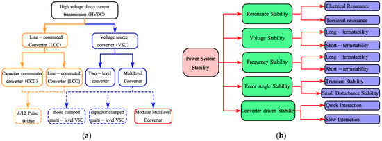
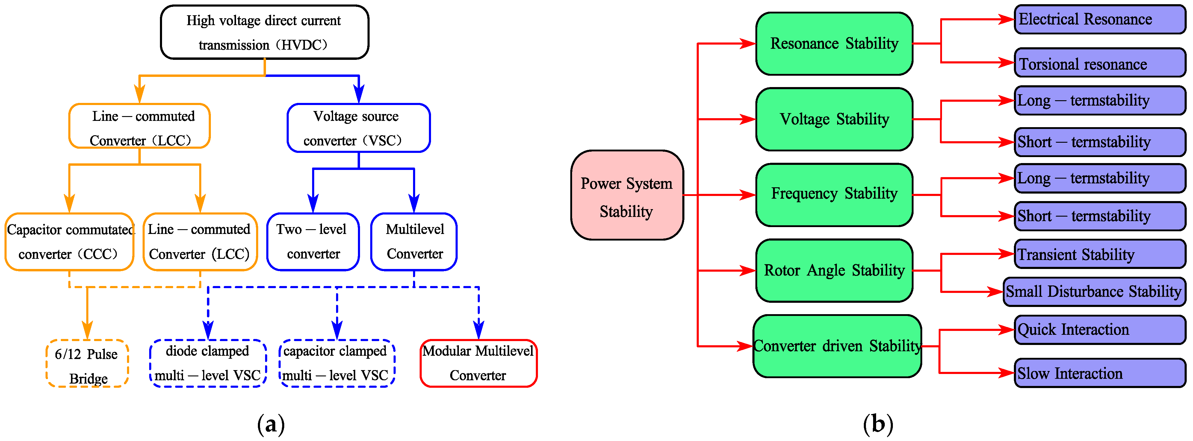
With the transformation of global energy structure and rapid development of clean energy, high−voltage direct current (HVDC) transmission technology has attracted widespread attention due to its advantages in long−distance, large−capacity, and high−efficiency power transmission [1,2]. Modular multilevel converter (MMC), as a mainstream topology of Voltage Source Converter (VSC) technology, has demonstrated enormous application potential in power grid interconnection, renewable energy integration, and power system stability enhancement due to its compact structure, operational flexibility, and low harmonic content [3,4]. Moreover, MMC−HVDC systems can effectively interconnect two asynchronous AC grids, improving grid flexibility and reliability [5]. However, as power systems impose increasingly higher performance requirements on MMC−HVDC technology, the research and optimization of its control strategies have become particularly urgent to meet diverse demands for system stability, reliability, and economics [6]. Figure 1 shows the Typical HVDC System and Power System Stability Classification.
Figure 1.
(a) The Typical HVDC System and (b) Power System Stability Classification.
The performance of MMC−HVDC systems depends on the design and implementation of their control strategies [7]. As a crucial component of VSC−HVDC technology, MMC can achieve independent regulation of active and reactive power through precise control strategies, thereby enhancing system dynamic response speed and steady−state operational performance [8,9]. Compared with traditional HVDC technology, MMC−HVDC can provide higher flexibility and efficiency without sacrificing system stability [10]. Additionally, MMC−HVDC technology shows significant potential for renewable energy integration, particularly in wind and solar power projects, offering more stable and reliable power transmission solutions [11,12]. Nevertheless, existing MMC−HVDC control strategies are mostly based on traditional PI or vector control, which suffer from complex parameter tuning, sensitivity to system parameter variations, and difficulty in coping with rapidly changing grid conditions [13,14]. The complex internal dynamics of MMC−HVDC systems make control strategy design and optimization critical for stable operation. Exploring novel control strategies to improve the adaptability and robustness of MMC−HVDC systems has become a research focus [15,16]. Although previous research has achieved certain results in improving conversion efficiency, optimizing predictive models through machine learning, and balancing submodule capacitor voltages, challenges remain in grid−side current control, system dynamic response, and harmonic suppression [17,18,19].
Model predictive control (MPC), as an advanced control strategy, can predict and optimize system behavior in advance, achieving precise control of complex dynamic systems [20,21]. Applying MPC to MMC−HVDC systems can significantly improve system dynamic response speed and steady−state accuracy while enhancing disturbance rejection capability [22,23,24]. However, many existing MPC implementations for MMC−HVDC focus solely on either current tracking or voltage regulation, often neglecting the synergistic integration of predictive dynamics with steady−state robustness. Moreover, few studies have systematically addressed the coordination between grid−side current control and DC voltage stabilization in wind−integrated HVDC systems under large disturbances [25,26,27]. Considering the impact of grid−side current on MMC−HVDC system control, this paper focuses on a dual closed−loop MPC strategy based on grid−side current, aiming to explore an efficient and stable control approach through theoretical analysis and simulation verification to address rapidly changing grid conditions and complex operational scenarios.
To address these gaps, this paper proposes a dual−loop MPC−PI hybrid control strategy, in which the inner MPC loop ensures fast grid−side current tracking, while the outer PI loop maintains DC voltage stability. The main contributions are as follows: (1) a structured hybrid control framework for MMC−HVDC; (2) detailed implementation from continuous MPC output to discrete submodule switching via Nearest Level Modulation (NLM); and (3) comprehensive simulation validation under energization and fault scenarios for a large−scale wind−integrated system.
2. MMC Topology and Steady−State Model
VSC−HVDC systems typically adopt two−level or three−level topologies (Figure 2), which feature simple structures but rely on large DC capacitors to maintain voltage and are prone to DC−side faults.
Figure 2.
Simplified circuit diagram of VSC−HVDC.
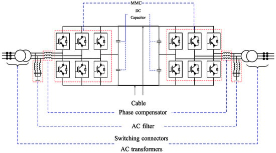
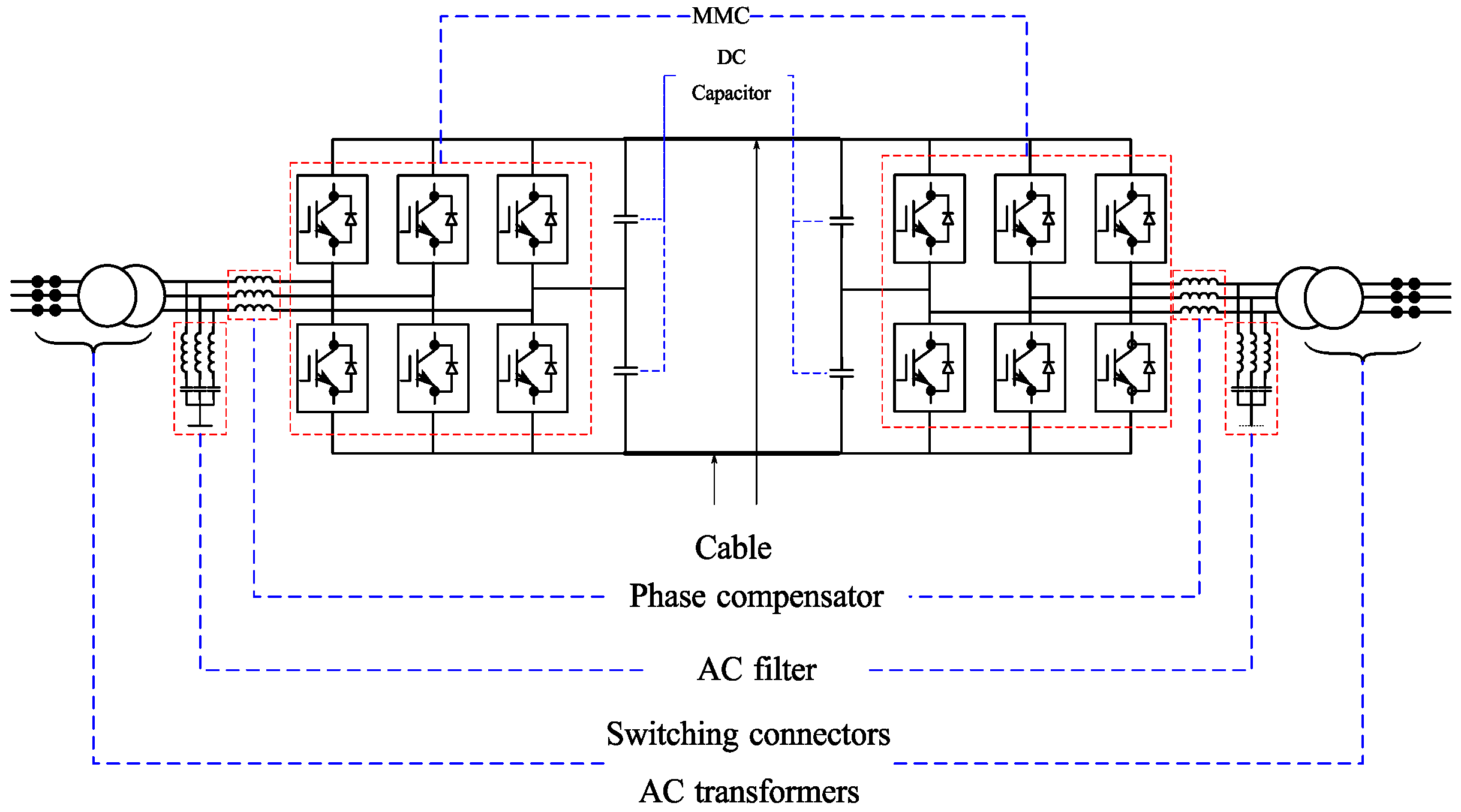
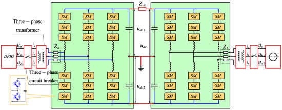
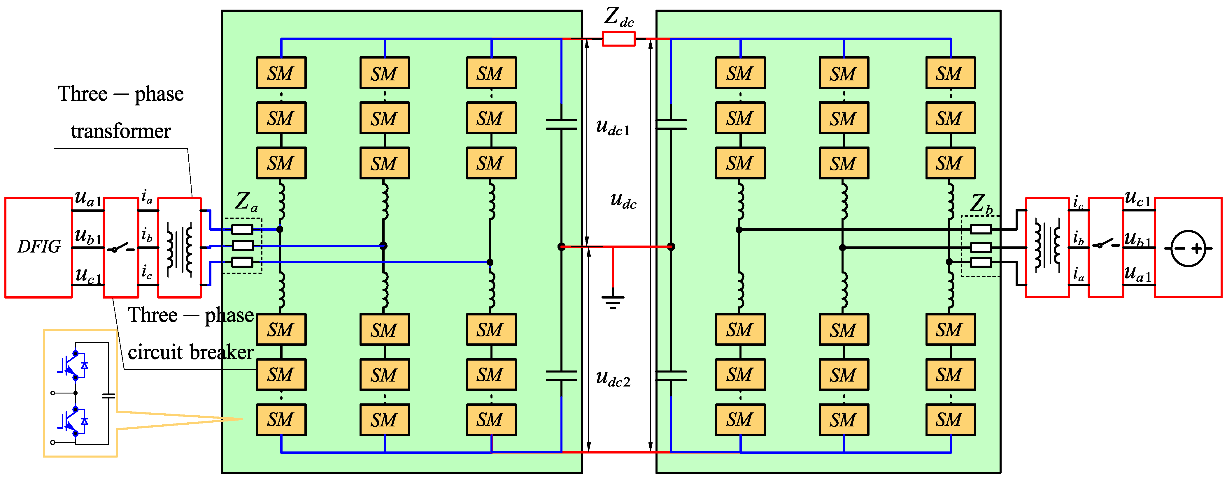
In contrast, MMC−HVDC systems (Figure 3) employ a modular multilevel structure that reduces switching losses and improves voltage output stability [28]. Due to the series connection of submodules, the voltage output is more stable with lower harmonic content. When some submodules fail, the system can continue operating, demonstrating good fault tolerance. This topology is suitable for large−scale renewable energy integration such as wind farms and solar systems as well as multi−terminal DC systems [29].
Figure 3.
MMC−HVDC topology diagram.
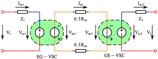
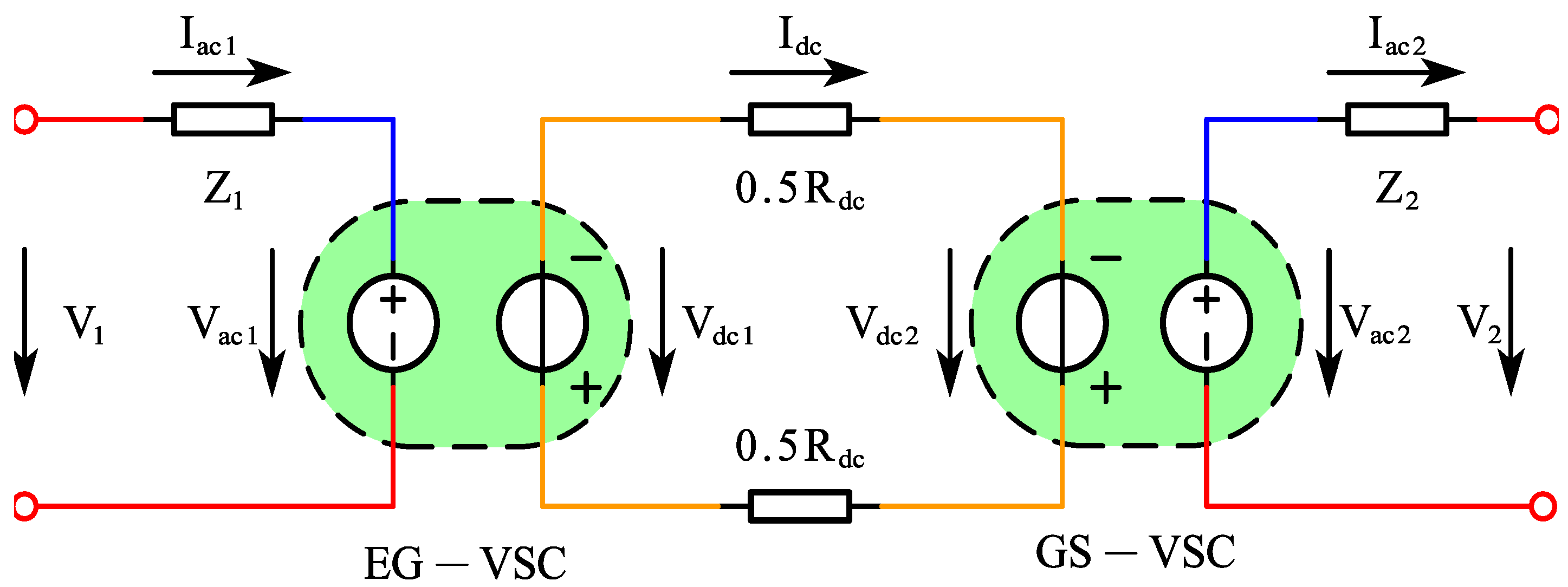
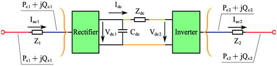
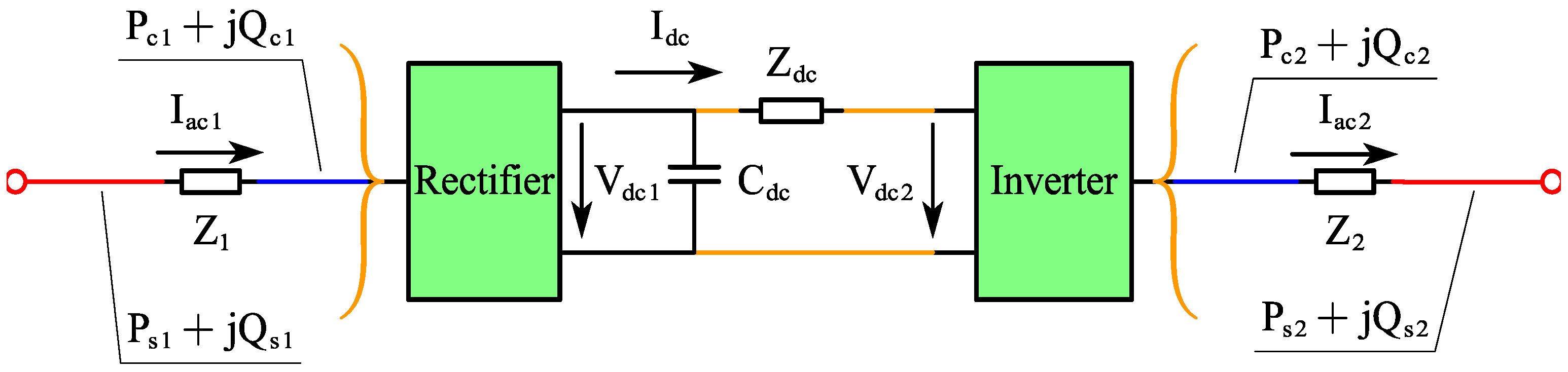
A steady−state model of the MMC−HVDC system is established by analyzing a point−to−point MMC−HVDC model with a Doubly Fed Induction Generator (DFIG) connected to the AC grid [30]. The DFIG−side and grid−side MMCs control the amplitude and frequency of AC terminal voltage for power generation, maintain stable DC voltage, and provide reactive power support to the AC grid. Figure 4 shows the simplified steady−state circuit of the point−to−point MMC−HVDC link.
Figure 4.
Steady−state voltage model of MMC−HVDC.
In Figure 4, V1 is the DFIG terminal AC voltage; V2 is the grid−side terminal AC voltage; Vac1 is the DFIG MMC AC−side voltage; Vac2 is the grid MMC AC−side voltage; Vdc1 is the DFIG MMC DC−side voltage; Vdc2 is the grid MMC DC−side voltage; Iac1 is the DFIG MMC AC−side current; Iac2 is the grid MMC AC−side current; Idc is the DC transmission line current; Z1 and Z2 are the sum of commutation reactor impedances and equivalent switching loss impedances for DFIG and grid MMC, respectively; and Rdc is the DC transmission cable resistance. The relationship between AC− and DC−side voltages for DFIG and grid MMC is
where M1 and M2 are the modulation indices for DFIG and grid MMC, respectively. To achieve independent control of active and reactive power, a decoupled current controller is employed. Figure 5 illustrates the power transfer model.
Figure 5.
Steady−state power transfer model of MMC−HVDC system.
The AC equivalent impedances for rectifier and inverter sides are
Consequently, the power transfer model at the DFIG MMC side is
The power transfer model at the grid MMC side is
where PS1 and PS2 are the real power at input and output sides; QS1 and QS2 are the reactive power at input and output sides; PC1 and PC2 are the real power at rectifier and inverter sides; and QC1 and QC2 are the reactive power at rectifier and inverter sides.
3. Dual Closed−Loop Controller Design
3.1. Fundamentals of MPC and Dual Closed−Loop Control
MPC utilizes a system model to predict future dynamics and obtains optimal control actions by solving an optimization problem online within a finite time horizon. Assuming a linear discrete system state−space representation:
where x(k) is the state variable, u(k) is the control input, and y(k) is the output. MPC employs the discrete state−space model to predict system state output trajectories Y = {y(k + 1|k), y(k + 2|k), …, y(k + Np|k)} over a prediction horizon Np based on current system state x(k) and a hypothetical future control sequence U = {u(k), u(k + 1), …, u(k + Nc − 1)}.
To achieve the optimization objective, an optimal future control sequence U* is assumed to exist that minimizes the cost function J. The cost function is designed as a weighted sum of tracking error and control effort:
where Q and R are weighting matrices that determine the trade−off between tracking accuracy and control effort; Nc is the control horizon (Nc ≤ Np); and Δu is the control increment rate. During optimization, system constraints are incorporated as boundary conditions:
After solving for the optimal control sequence U*, only the first element u*(k) is applied to the controlled plant. At the next sampling period (k + 1), the state x(k + 1) is updated with new measurements and the prediction process is repeated.
Traditional dual−loop controllers typically employ PI controllers for both inner and outer loops. However, conventional linear PI controllers cannot directly handle system constraints, and their performance degrades with system parameter variations (e.g., load changes, inductance drift), resulting in poor robustness. Therefore, this paper designs a dual closed−loop MMC−HVDC control system combining a PI outer loop with an MPC inner loop.
3.2. MPC Dual Closed−Loop Controller Design
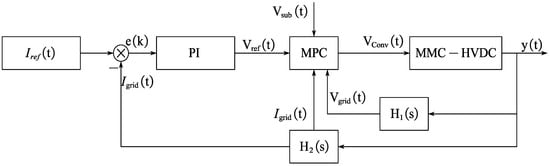
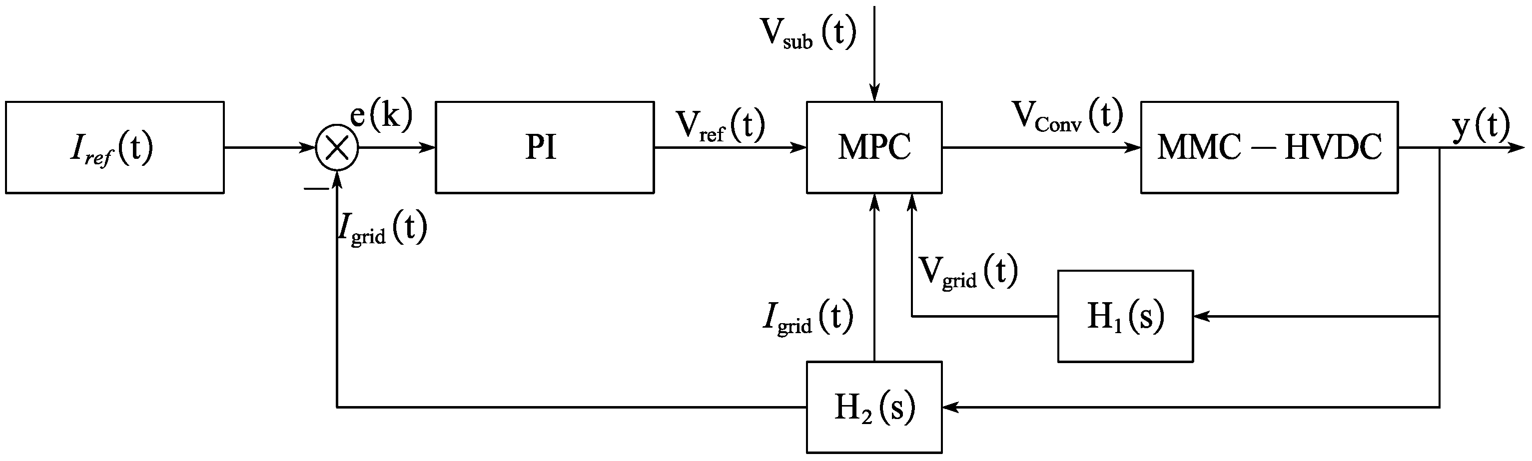
The dual closed−loop MPC model for MMC−HVDC combines MPC’s optimization capability with closed−loop control stability [31]. The primary task of the inner current loop is to respond rapidly to grid−side current changes by adjusting inverter switching states to control current amplitude and phase [32]. For the MMC−HVDC system, the control model is established as shown in Figure 6.
Figure 6.
Principle of MPC dual closed−loop control system compensation.
For grid−side current−based control, the focus is on the current control loop. Considering the grid−side current Igrid, the converter dynamics can be expressed by the following differential equation:
where L is the grid−side inductance, R is the grid−side resistance, Vgrid is the grid voltage, and Vconv is the converter−generated voltage. Since Vconv is determined by submodules, it can be expressed as a function of submodule states:
where Nsub is the number of submodules per arm and Vsub is the voltage of each submodule. MMC capacitor voltage balance must be considered. For each submodule i, the capacitor voltage Vsub,i can be expressed as
where C is the capacitance and Isub,i is the submodule current. The control objective is to design an MPC controller that adjusts converter voltage to control grid−side current, making it track the reference value Iref. Therefore, the state vector is set as x(k) = [Igrid(k)], the input vector as u(k) = [Vconv(k)], and the output vector as y(k) = [Igrid(k)], yielding the following state equation:
The inner loop control objective is to make the actual current track the reference current rapidly. The MPC strategy aims to minimize the sum of squared current deviations over the prediction horizon. The cost function J is
where Iref(k+i) is the reference current at k + i; Q and R are weighting matrices for adjusting tracking performance and control rate, respectively; and N is the prediction and control horizon length. The optimal control sequence u is obtained by
The outer loop maintains system voltage at preset levels by introducing a Proportional–Integral (PI) controller to adjust the reference current Iref(k+i):
where Kp and Ki are proportional and integral gains, and Vref is the voltage reference. The inner and outer loop controllers are integrated to form the dual closed−loop MPC model through the following steps:
- Calculate reference current Iref(k) based on voltage deviation.
- Optimize control variables based on Iref(k) and system dynamic model to minimize current deviation.
- Iterate the optimization process within the control period t to achieve precise control of system current and voltage.
- In dual closed−loop MPC, both inner and outer loop strategies predict future current and voltage variations based on system mathematical models for control decision−making.
4. Results
4.1. System Design
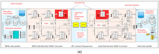
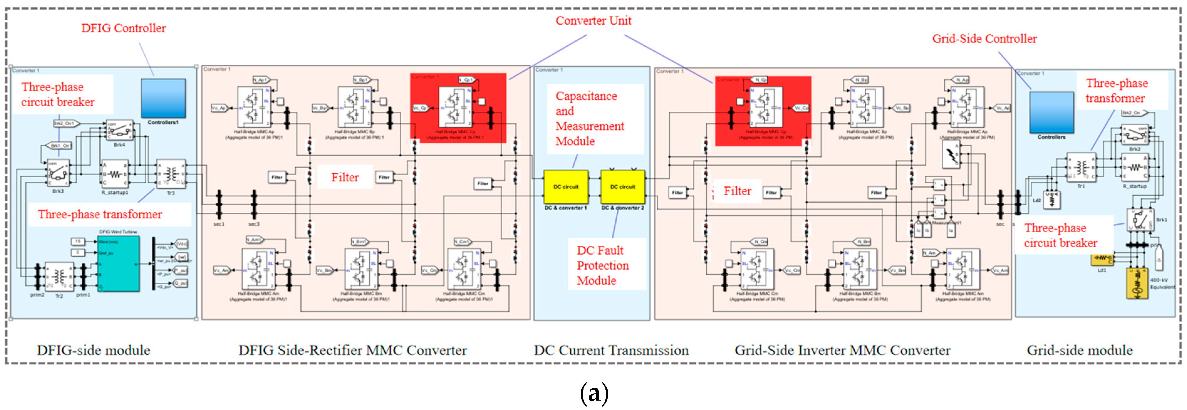
A 1000 MW wind power generation MMC−HVDC simulation model was built using Simulink (Figure 7a). The 1000 MW rating is chosen to represent a large−scale offshore wind farm cluster, which is typical for modern HVDC transmission projects (e.g., North Sea wind farms). The system comprises Doubly Fed Induction Generator (DFIG) modules (consisting of 666 × 1.5 MW wind turbines), a generator−side MMC rectifier module, DC transmission module, a grid−side MMC inverter module, and a 400 kV grid−side module. The MPC dual closed−loop controller structure is implemented as described in Section 3.2. Key parameters of the simulation MMC−HVDC system model are shown in Table 1.
Figure 7.
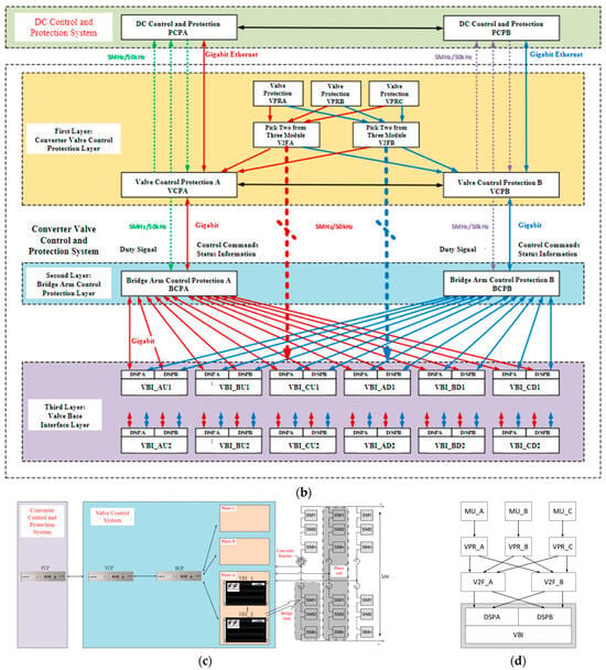
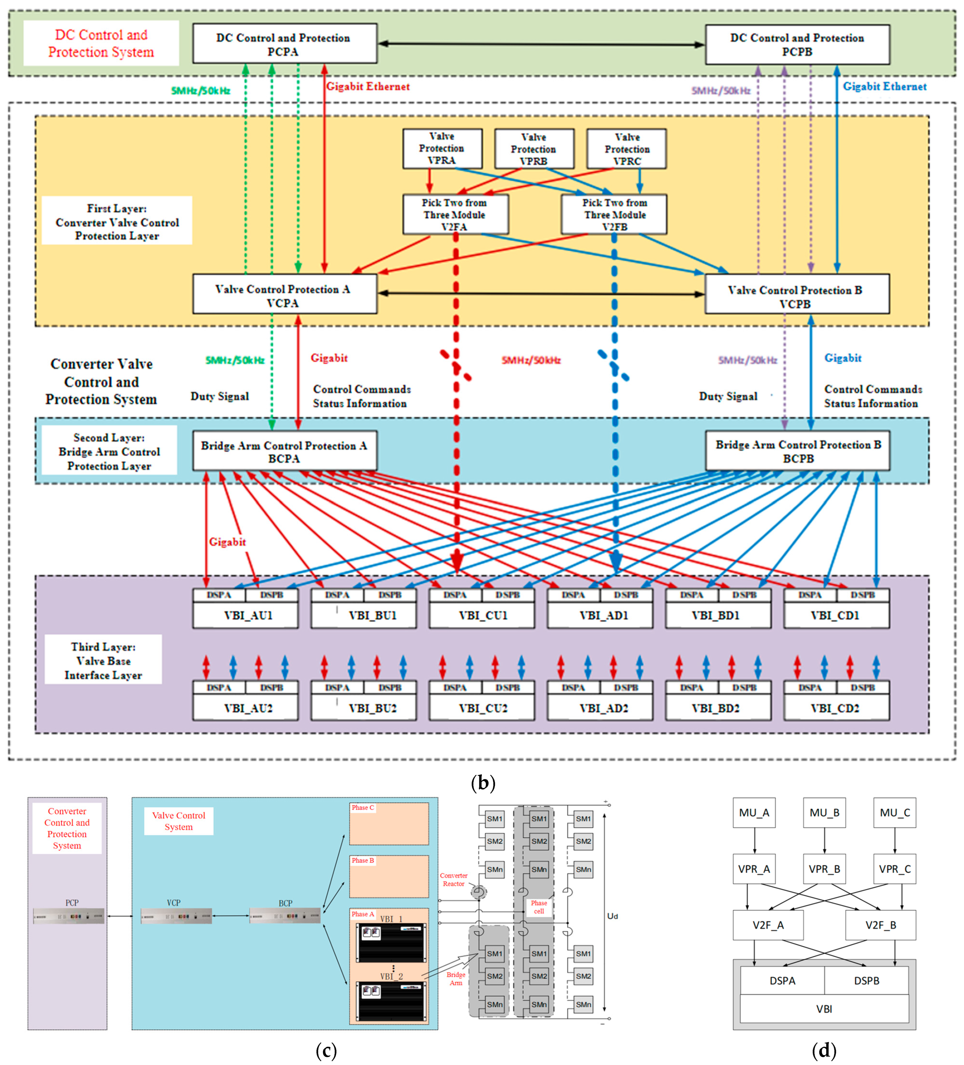
MMC−HVDC System. (a) Simulation and Design. (b) Valve Control Signal Flow Diagram. (c) Valve Control System. (d) Valve Protection System.
Table 1.
Key parameters of the simulated MMC−HVDC system.
In actual system design, the control system primarily consists of VCP (Valve Control Protection) units, PCP units, BCP (Bridge Arm Control Protection) units, and VBI (Valve Base Interface) units.
The VCP device implements communication with the PCP as well as NLM, active charging, and circulating current control functions. The BCP device handles submodule voltage sequencing, fault handling, and IGBT switching command generation. The VBI device interfaces with the SMC to execute module command distribution and status information aggregation. The control system architecture is shown in Figure 7c, with the control signal flow diagram depicted in Figure 7b.
In the valve protection system, the design incorporates three sets of VPR protection and two sets of V2F (two−out−of−three) protection. These are independently configured on the hardware to achieve cross−connection in Figure 7d, where
- VPR device: Communicates with the measurement system to perform judgments such as temporary lockout, arm overcurrent protection, and arm current imbalance protection;
- V2F Unit: Implements a three−out−of−two arbitration logic for protection signals: switches to two−out−of−one when one protection set fails, and to one−out−of−one when two protection sets fail.
- The V2F output sends a rapid lockout signal to the VBI, cross−connected to enable the VBI to directly execute lockout commands.
4.2. Results Analysis
To validate the control performance of the proposed controller, the DFIG−side MMC adopts a conventional controller, while the grid−side MMC employs the proposed dual−loop MPC strategy. The voltage and current on the DFIG side, the DC transmission line, and the grid side are analyzed under system energization and disturbance conditions. Table 2 shows the operational status table for MMC−HVDC system at each moment.
Table 2.
The operational status table for MMC−HVDC system.
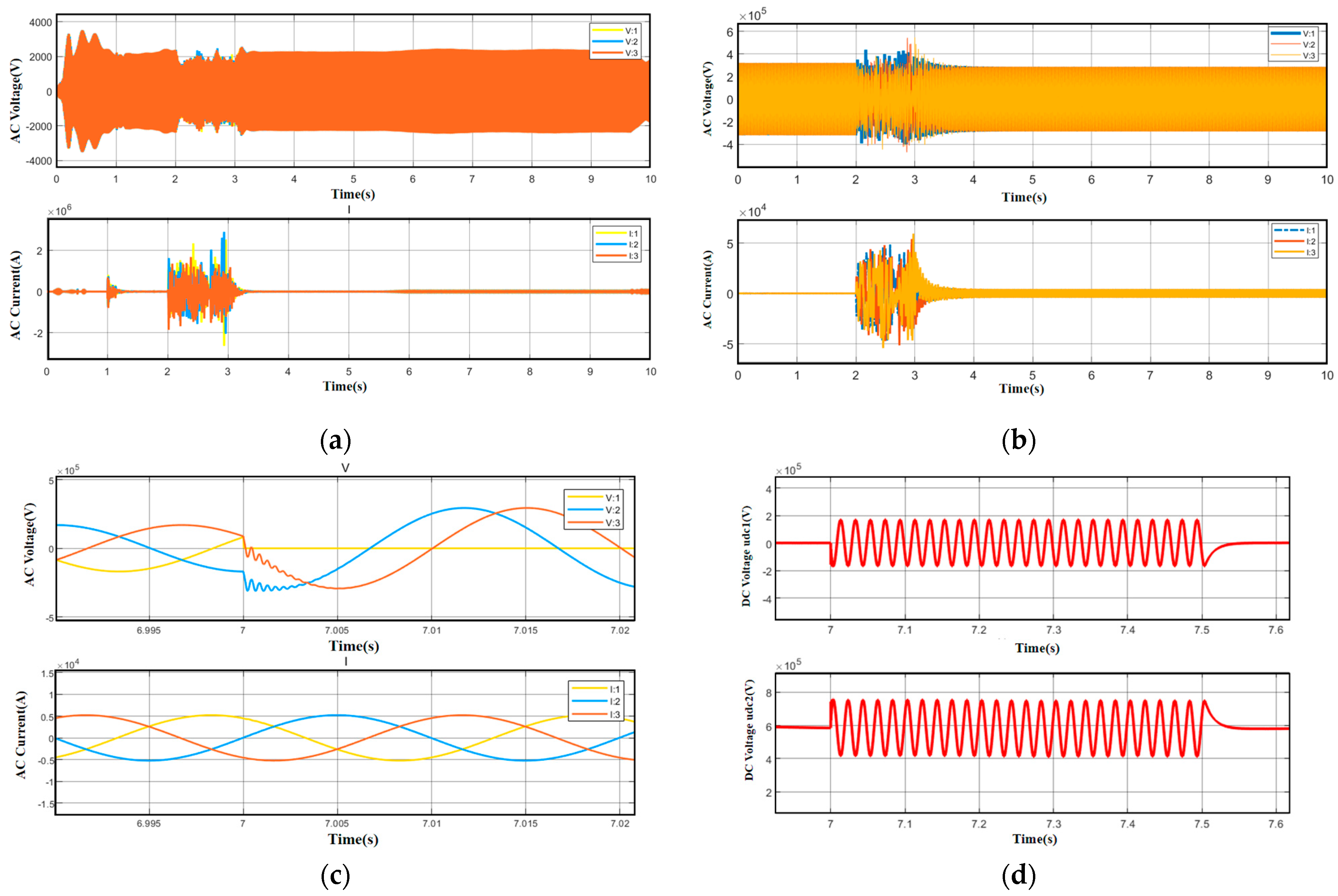
At t = 0.1 s, the DFIG three−phase circuit breaker closed; At t = 0.5 s, the DFIG three−phase series Resistance(R_startup) switching from high impedance (400 Ω) to low impedance (0.01 Ω) state; At t = 1 s, the DFIG−side MMC is Deblocked; At t = 2 s, the grid−side MMC is Deblocked; At t = 7 s, A−phase conductor of the grid−side MMC has a short−circuit to ground fault; and at t = 7.5 s, fault cleared.
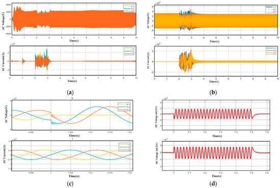
Figure 8a shows the AC voltage and current waveforms on the DFIG side. Minor current variations in the period 0–1 s are due to system initialization and soft−start sequence transients (see Table 2), prior to the main DFIG−side MMC energization at t = 1.0 s. These do not affect the subsequent analysis of control performance. When the DFIG−side MMC is energized at t = 1 s, minor fluctuations occur in the AC voltage and current, which stabilize within 0.3 s. At t = 2 s, when the grid−side MMC is energized, fluctuations are observed in both the DFIG−side and grid−side AC voltages and currents, which settle within 1 s. The results in Figure 8a indicate that the energization of both MMCs affects the DFIG−side voltage and current to some extent.
Figure 8.
(a) DFIG−side AC voltage and current curves (b) grid−side voltage and current variation curves (c) grid−side MMC converter A−phase short−circuit to ground fault (d) Udc1 and Udc2 change curves during an A−phase fault.
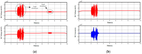
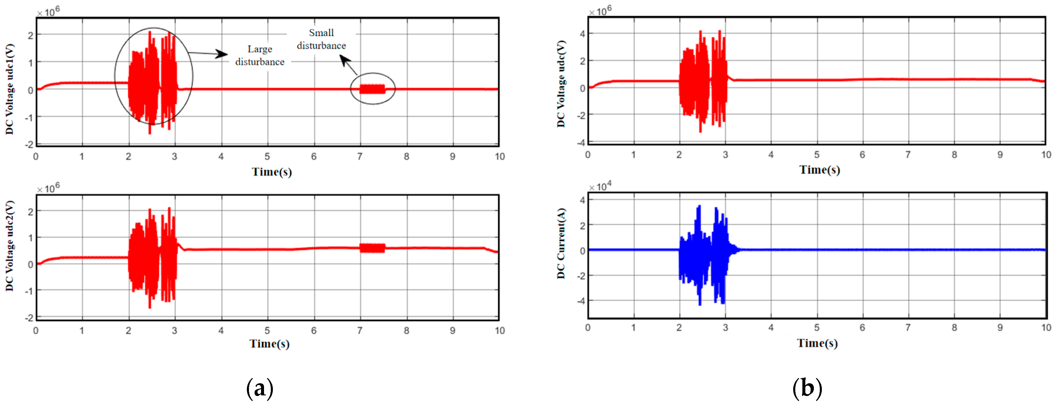
Figure 8b and Figure 9a display the waveforms of DC voltages udc1 and udc2, DC voltage udc, and grid-side AC voltage and current, respectively. The DC voltage is affected when the grid-side MMC is energized at t = 2 s. At t = 7 s, when the phase-A fault occurs on the grid-side MMC, udc1 and udc2 exhibit fluctuations. However, the DC voltage udc and DC current Idc remain stable, with no impact on the grid-side voltage and current. Figure 9b illustrates DC voltage and current variations. These results demonstrate that despite disturbances, the system maintains stable operation.
Figure 9.
(a) Upper and lower DC voltage curves; (b) DC voltage and current curves.
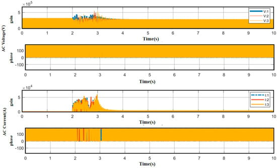
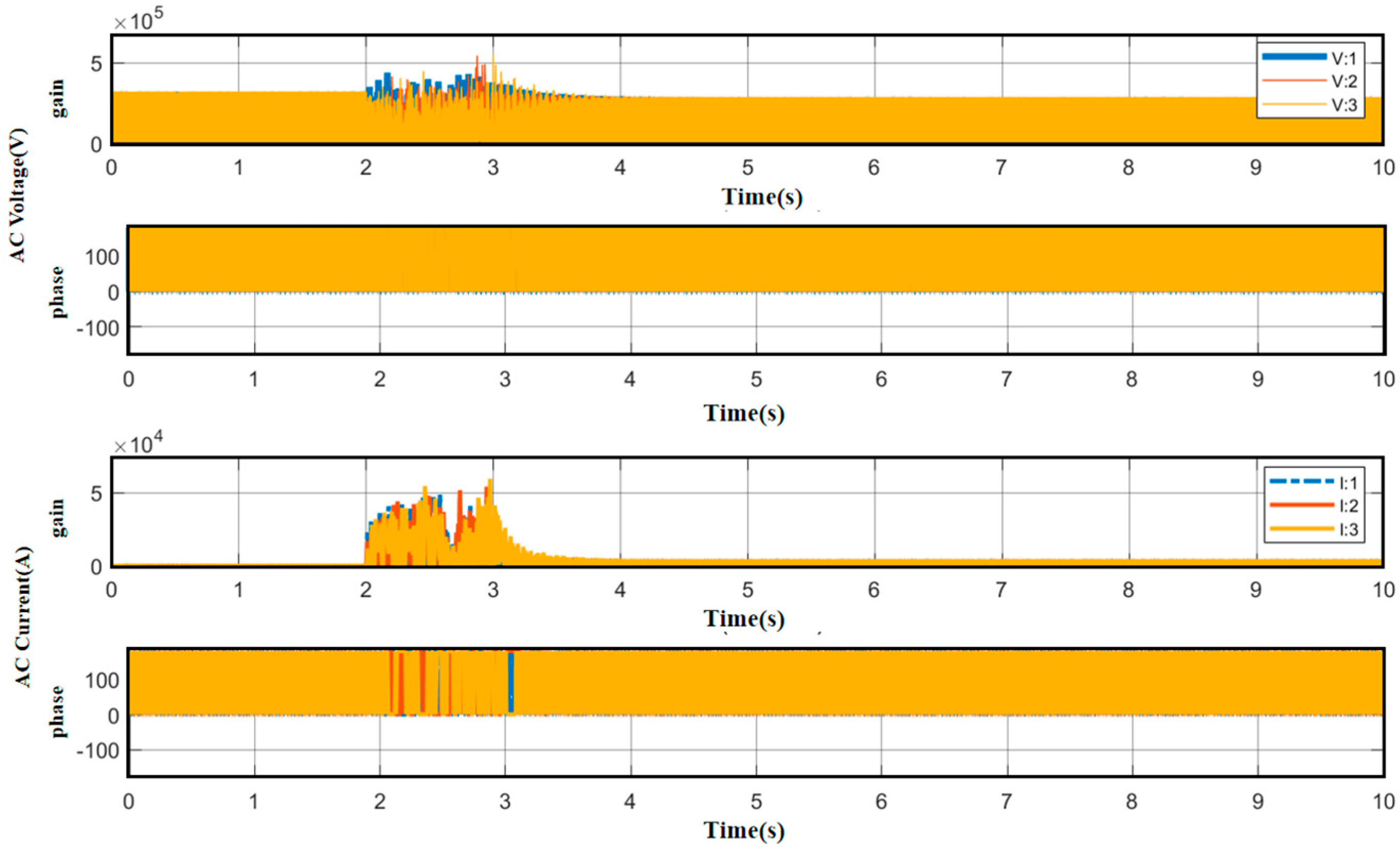
Figure 10 shows the gain–phase curves of grid−side voltage and current, revealing that, except for minor fluctuations during converter unlocking, the grid−side voltage and current curves remain essentially unaffected by system disturbances.
Figure 10.
Grid−side voltage and current magnitude–phase curves.
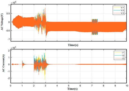
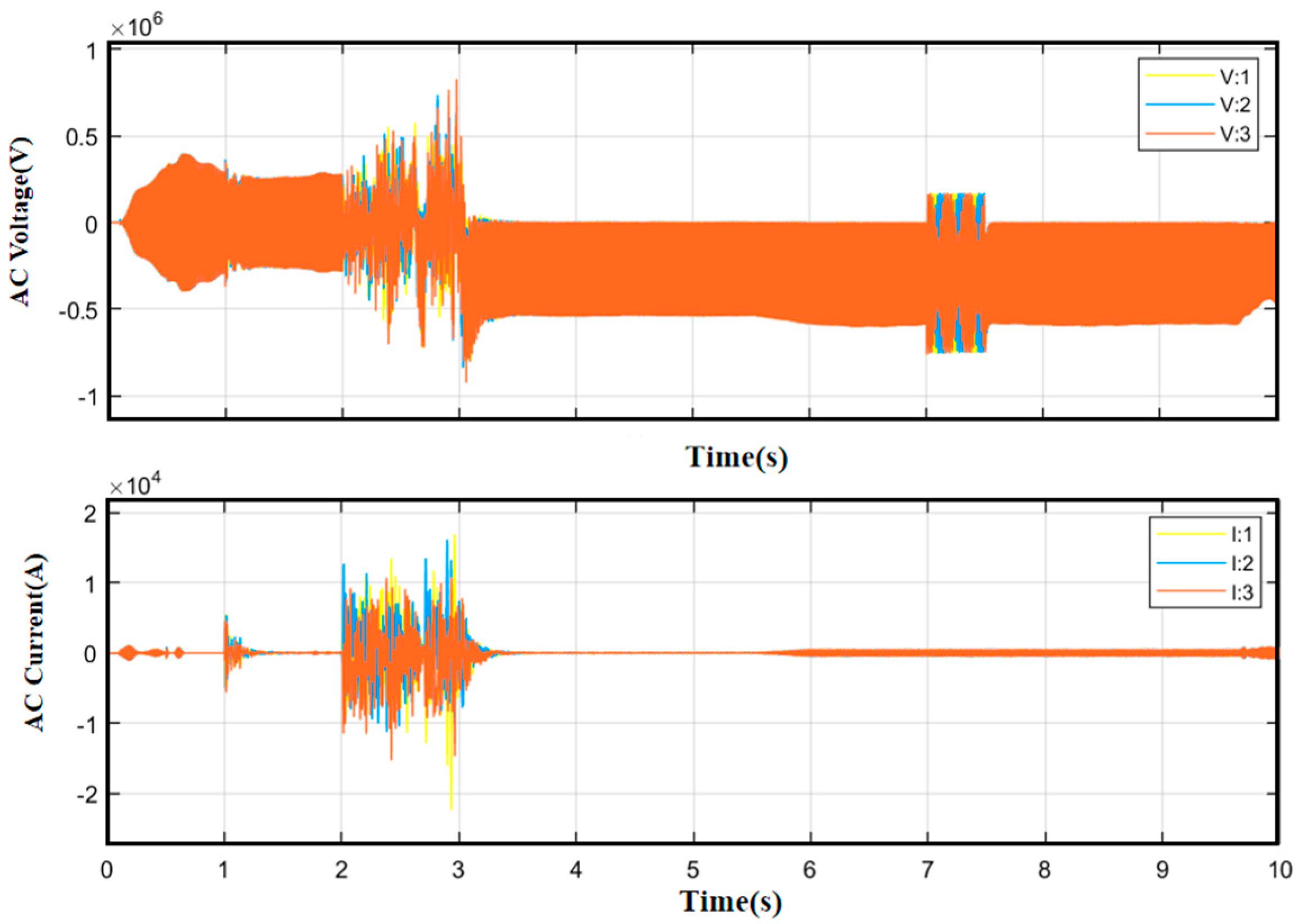
For performance comparison, Figure 11 presents grid−side voltage and current curves under conventional dual−loop PI control. The conventional control exhibits larger control errors, with maximum voltage fluctuation reaching 820 kV at 2 s during MMC unlocking—54.7% higher than the 530 kV fluctuation observed with the proposed MPC strategy (Figure 8b). The conventional control also shows grid fluctuations at the 7 s fault instant. During the fault, for the conventional PI control, the maximum voltage difference (Vmax−Vmin) deviation at the grid side during the fault reaches approximately 129 kV. In contrast, under the proposed hybrid PI−MPC control, the maximum deviation is limited to about 114 kV—a reduction of approximately 13.2%.
Figure 11.
Conventional double−loop control grid−side voltage and current variation curves.
The comparative results demonstrate that the dual−loop MPC can rapidly predict and adjust outputs during significant grid−side current fluctuations, effectively suppressing current oscillations and ensuring stable system operation.
5. Discussion
The proposed dual closed−loop MPC strategy exhibits superior performance compared with conventional PI−based approaches. The MPC inner loop’s predictive capability enables proactive compensation for disturbances, while the PI outer loop ensures steady−state voltage accuracy. The integration of these two control methodologies addresses the limitations of traditional linear controllers in handling system constraints and parameter variations. The simulation results validate that the MPC−based approach significantly reduces transient overshoot and settling time during converter unlocking and fault conditions.
The 54.7% reduction in voltage fluctuation magnitude during converter unlocking illustrates the effectiveness of predictive control in anticipating system behavior. Furthermore, the robust performance during phase−A faults demonstrates the strategy’s potential for enhancing system reliability under grid disturbances. The modular nature of MPC formulation allows straightforward incorporation of additional constraints, such as current limits and submodule voltage balancing, which is particularly advantageous for MMC applications.
While this study demonstrates the potential of the proposed hybrid MPC−PI control, certain limitations should be acknowledged. The simulation assumes uniform wind conditions and does not capture full wind variability or turbine−level dynamics. Additionally, the control design assumes perfect system parameter knowledge; robustness under parameter uncertainties warrants further investigation. Future work will focus on (1) hardware−in−the−loop validation, (2) incorporation of wind speed and load variations, (3) extension to multi−terminal HVDC grids, and (4) real−time computational optimization for embedded implementation.
6. Conclusions
This study proposes and validates a dual−loop MPC−PI hybrid control strategy for MMC−HVDC systems in wind power integration. The hybrid structure leverages MPC for fast current tracking and PI for voltage stabilization, showing, in simulation, a voltage overshoot reduction of over 50% compared to conventional PI control under energization and fault conditions. The control framework is implemented through a combined MPC−NLM approach, ensuring practical applicability. The research provides a foundation for more robust and adaptive control designs in renewable−rich HVDC grids, with particular relevance for offshore wind farms and multi−terminal systems. Future efforts will pursue experimental validation and real−time implementation.
Author Contributions
Conceptualization, D.L. and X.L.; Methodology, X.C.; Software, D.B.; Formal analysis, J.Z.; Investigation, Z.H. and L.H.; Writing—review and editing, Y.M. All authors have read and agreed to the published version of the manuscript.
Funding
This research was produced under the China Southern Power Grid Science and Technology Project: Research and Engineering Application of Autonomously Controllable Flexible DC Converter Valve Control Devices (030500KC23100009).
Data Availability Statement
The original contributions presented in this study are included in the article. Further inquiries can be directed to the corresponding author.
Conflicts of Interest
Authors Duanjiao Li and Yanjun Ma were employed by the Guangdong Power Grid Co., Ltd. Author Xinxin Chen was employed by the Shantou Power Supply Bureau of Guangdong Power Grid Co., Ltd. Authors Junjun Zhang and Zhaoqing Hu were employed by the NR Electric Co., Ltd. The remaining authors declare that the research was conducted in the absence of any commercial or financial relationships that could be construed as a potential conflict of interest.
Abbreviations
The following abbreviations are used in this manuscript:
| MMC | Modular Multilevel Converter |
| MPC | Model Predictive Control |
| VSC | Voltage Source Converter |
| DFIG | Doubly Fed Induction Generator |
| HVDC | High−Voltage Direct Current |
References
- Li, R.; Yu, L.; Xu, L.; Adam, G.P. Coordinated Control of Parallel DR-HVDC and MMC-HVDC Systems for Offshore Wind Energy Transmission. IEEE J. Emerg. Sel. Top. Power Electron. 2020, 8, 2572–2582. [Google Scholar] [CrossRef] [Scilit]
- Lv, J.; Zhang, J.; Zhi, Y.; Wang, K.; Ge, P.; Zhang, J.; Li, Q. Cooperative Control Method Based on Two-Objective Co-Optimization for MMCs in HVDC Systems. Processes 2025, 13, 1839. [Google Scholar] [CrossRef] [Scilit]
- Zheng, Z.; Zou, Y.; Xie, Q.; Liu, L.; Ren, J.; Xiao, X.; Zhang, J. Side Effect of VSC-HVDC on Commutation Failure in LCC-HVDC Caused by Sending End AC Faults. IEEE Trans. Power Deliv. 2024, 39, 1310–1313. [Google Scholar] [CrossRef] [Scilit]
- Aguilar Marin, J.L.; Cisneros Villalobos, L.; Vera-Dimas, J.G.; Sánchez Jaime, J.; Saldarriaga-Noreña, H.A.; Herrera Gutiérrez, H. Mitigation of Magnetic Field Levels in Bipolar Transmission Lines of 500 and 600 kV in HVDC. Energies 2025, 18, 5022. [Google Scholar] [CrossRef] [Scilit]
- Ling, X.; Xi, J.; Guo, Q.; Yu, X.; Zhao, X. HVDC Receiving-End Power Grid Multi-Resource Coordinated Transient Voltage Emergency Control Technology Based on Transient Voltage Similarity. Electronics 2025, 14, 4090. [Google Scholar] [CrossRef] [Scilit]
- Wang, Y.; Aksoz, A.; Geury, T.; Ozturk, S.B.; Kivanc, O.C.; Hegazy, O. A Review of Modular Multilevel Converters for Stationary Applications. Appl. Sci. 2020, 10, 7719. [Google Scholar] [CrossRef] [Scilit]
- Debnath, S.; Qin, J.; Saeedifard, M. Operation, control, and applications of the modular multilevel converter: A review. IEEE Trans. Power Electron. 2015, 30, 37–53. [Google Scholar] [CrossRef] [Scilit]
- Alharbi, M.; Mobarrez, M.; Bhattacharya, S. Control and performance analysis methodology for scale-up of MMC submodules for back-to-back HVDC applications. In Proceedings of the 2017 IEEE Applied Power Electronics Conference and Exposition (APEC), Tampa, FL, USA, 26–30 March 2017; pp. 440–447. [Google Scholar] [CrossRef] [Scilit]
- Van der Sande, R.; Huwyler, A.; Shekhar, A.; Bauer, P. Dynamic DC Voltage Enhancement for Modular Multilevel Converter Using Capacitor Voltage Ripple. IEEE Trans. Power Electron. 2025, 40, 8179–8193. [Google Scholar] [CrossRef] [Scilit]
- Antonopoulos, A.; Ängquist, L.; Harnefors, L.; Nee, H.-P. Optimal selection of the average capacitor voltage for variable-speed drives with modular multilevel converters. IEEE Trans. Power Electron. 2015, 30, 227–234. [Google Scholar] [CrossRef] [Scilit]
- Wang, W.; Xiong, X.; Yang, D.; Wang, S.; Dong, X. Operational Risk Assessment of Power Imbalance for Power Systems Considering Wind Power Ramping Events. Processes 2025, 13, 1779. [Google Scholar] [CrossRef] [Scilit]
- Liu, M.; Zhang, L.; Wu, Q.; Zhang, K.; Li, X.; Zhao, B. Research on Power Stability of Wind-Solar-PEM Hydrogen Production System Based on Virtual Synchronous Machine Control. Processes 2025, 13, 1733. [Google Scholar] [CrossRef] [Scilit]
- Qin, J.; Saeedifard, M. Predictive control of a modular multilevel converter for a back-to-back HVDC system. IEEE Trans. Power Deliv. 2012, 27, 1538–1547. [Google Scholar] [CrossRef] [Scilit]
- Zhang, G.; Xiang, W.; Chen, X.; Wen, J. Capacity Design of Cascaded Diode Rectifier-MMC Based HVDC for Offshore Wind Farm Integration. IEEE Trans. Power Deliv. 2024, 39, 2908–2919. [Google Scholar] [CrossRef] [Scilit]
- Sánchez-Sánchez, E.; Prieto-Araujo, E.; Junyent-Ferré, A.; Gomis-Bellmunt, O. Analysis of MMC energy-based control structures for VSC-HVDC links. IEEE Trans. Emerg. Sel. Top. Power Electron. 2018, 6, 1065–1076. [Google Scholar] [CrossRef] [Scilit]
- Miao, S.; Yu, L.; Zhu, J.; Zhao, C. Control of series-connected diode rectifier and MMC for three-wire-bipolar-structure based HVDC. In Proceedings of the 18th IET International Conference on AC and DC Power Transmission (ACDC 2022), Online, 2–3 July 2022; pp. 270–277. [Google Scholar] [CrossRef] [Scilit]
- Fuchs, S.; Biela, J. Reducing losses and energy storage requirements of modular multilevel converters with optimal harmonic injection. IEEE Access 2023, 11, 21283–21299. [Google Scholar] [CrossRef] [Scilit]
- Ba, D.; Yu, F.; Wang, Y.; Chen, X.; Niu, Y.; Lyu, X. Optimization Study of Parasitic Parameters in Parallel Interleaved Windings for High-Frequency PCB Transformers. IEEE Trans. Power Electron. 2025, 40, 14894–14907. [Google Scholar] [CrossRef] [Scilit]
- Lv, C.; Fan, H.; Zhang, Z.; Fan, M.; Run, W.; Yang, L.; Yang, Y.; Liu, D. Ultra-Short-Term Power Prediction for Distributed Photovoltaics Based on Time-Series LLMs. Electronics 2025, 14, 4519. [Google Scholar] [CrossRef] [Scilit]
- Villa-Ávila, E.; Ochoa-Correa, D.; Arévalo, P. Advancements in Power Converter Technologies for Integrated Energy Storage Systems: Optimizing Renewable Energy Storage and Grid Integration. Processes 2025, 13, 1819. [Google Scholar] [CrossRef] [Scilit]
- Soza Mamani, K.M.; Prado Romo, A.J. Integrating Model Predictive Control with Deep Reinforcement Learning for Robust Control of Thermal Processes with Long Time Delays. Processes 2025, 13, 1627. [Google Scholar] [CrossRef] [Scilit]
- Tarcar, R.K.; Shetgaonkar, A.; Popov, M.; Lekić, A. Large Signal Stability Assessment of MPC-based Control for HVDC Electrical Grid. In Proceedings of the 2024 IEEE PES Innovative Smart Grid Technologies Europe (ISGT Europe), Dubrovnik, Croatia, 21–24 October 2024; pp. 1–6. [Google Scholar] [CrossRef] [Scilit]
- Ba, D.; Chen, G.; Li, P.; An, K.; Liu, X. Fuzzy Smith predictor–based active disturbance rejection controller for time-delay systems with application to drilling stick–slip vibration control. Proc. Inst. Mech. Eng. Part I J. Syst. Control Eng. 2023, 237, 401–414. [Google Scholar] [CrossRef] [Scilit]
- Du, X.; Li, L.; Zhang, F.; Li, Q.; Wang, Z. Research on Virtual Synchronous Control of MMC-HVDC Inverter Based on Model Predictive Control. In Proceedings of the 2024 International Conference on HVDC (HVDC), Urumqi, China, 20–22 November 2024; pp. 1–6. [Google Scholar] [CrossRef] [Scilit]
- Wu, J.; Li, J.; Wang, H.; Li, G.; Ru, Y. Fault-Tolerant Three-Vector Model-Predictive-Control-Based Grid-Connected Control Strategy for Offshore Wind Farms. Electronics 2024, 13, 2316. [Google Scholar] [CrossRef] [Scilit]
- Kadhum, H.T.; Watson, A.J.; Rivera, M.; Zanchetta, P.; Wheeler, P. Optimised Model Predictive Control for MMCs: Enhancing Performance and Reducing Computational Burden. IEEE Trans. Ind. Appl. 2025. early access. [Google Scholar] [CrossRef] [Scilit]
- Bhutto, M.U.; Soomro, J.B.; Ali, K.H.; Memon, A.A.; Ansari, J.A.; Alamri, B.; Alqarni, M. Innovative model predictive control for HVDC: Circulating current mitigation and fault resilience in Modular Multilevel converters. Front. Energy Res. 2024, 12, 1345032. [Google Scholar] [CrossRef] [Scilit]
- Mourouvin, R.; Filliot, L.; Ghyselinck, A.; Dai, J.; Bacha, S.; Georges, D.; Benchaib, A. Real-Time Hierarchical MPC Applied to an MMC in Grid-Forming Mode: Implementation and Validation in Power Hardware-in-The-Loop. IEEE Trans. Power Deliv. 2023, 38, 3142–3154. [Google Scholar] [CrossRef] [Scilit]
- Zhao, C.; Huang, C.; Jiang, S.; Wang, R. Multimodal Switching Control Strategy for Wide Voltage Range Operation of Three-Phase Dual Active Bridge Converters. Processes 2025, 13, 1921. [Google Scholar] [CrossRef] [Scilit]
- Zhou, H.; Ju, P.; Xue, Y.; Zhu, J. Probabilistic equivalent model of DFIG-based wind farms and its application in stability analysis. J. Mod. Power Syst. Clean Energy 2016, 4, 248–255. [Google Scholar] [CrossRef] [Scilit]
- Guangjie, C.; Zheli, Y.; Zhaoyun, Z. Dual Closed-Loop Inverter Control System Based on Quasi-PR and PI. In Proceedings of the 2025 15th International Conference on Power, Energy, and Electrical Engineering (CPEEE), Fukuoka, Japan, 25–27 February 2025; pp. 428–432. [Google Scholar] [CrossRef] [Scilit]
- Murdan, A.P.; Jahmeerbacus, I.; Sayed Hassen, S.Z. Bandwidth oriented approach for the design of a PI controller for a three phase two-stage grid-connected PV system. Int. J. Electron. 2024, 111, 1033–1053. [Google Scholar] [CrossRef] [Scilit]

Disclaimer/Publisher’s Note: The statements, opinions and data contained in all publications are solely those of the individual author(s) and contributor(s) and not of MDPI and/or the editor(s). MDPI and/or the editor(s) disclaim responsibility for any injury to people or property resulting from any ideas, methods, instructions or products referred to in the content. |
© 2025 by the authors. Licensee MDPI, Basel, Switzerland. This article is an open access article distributed under the terms and conditions of the Creative Commons Attribution (CC BY) license.