


Abstract
Laboratories play a critical role in engineering education by bridging the gap between theoretical knowledge and practical applications. Dedicated laboratory stands serve as essential platforms for experiential learning, enabling students to interact directly with real or simulated systems. These stands enable a deeper understanding of complex engineering concepts and, at the same time, support the creation of essential skills such as problem-solving, critical thinking, and system integration. While physical laboratory stands provide a rich learning experience, their large-scale implementation can be both technically and financially challenging. In this context, virtual laboratory environments based on virtual prototypes offer a valuable complementary approach by improving access to practical learning while providing greater flexibility and reducing implementation costs. This paper presents the development of a virtual laboratory stand implemented using Simscape and designed for use in the teaching process in mechatronics engineering. The developed virtual prototype materializes a Segway-type self-balancing mobile robot and is used as a teaching tool in the lab activity of the control systems course. The educational effectiveness of the proposed virtual laboratory stand was evaluated by comparing students’ perceptions with those of a conventional analytical-model-based laboratory activity. The collected questionnaire data were analyzed using descriptive statistics and the Mann–Whitney U test. Students using the virtual laboratory reported consistently higher ratings than those using the analytical model, with statistically significant differences observed in three questionnaire items. These findings suggest that the proposed virtual laboratory stand enhances students’ learning experience and provides a valuable complementary approach for teaching control system design in mechatronics.
1. Introduction
In engineering education, a key objective, as defined in international frameworks such as the EUR-ACE accreditation system (Stefanova, 2022) and the CDIO Initiative (Crawley et al., 2014), is to prepare graduates to actively participate in and lead the processes of designing, manufacturing, and operating different systems, processes and projects. In this framework, laboratory activities play a central role in achieving this goal. According to the National Research Council (2006) report, learning in a laboratory facilitates students’ engagement in practical work and allows them to actively explore natural phenomena, products, or data, enabling them to deepen their understanding and effectively apply theoretical concepts.
While laboratory-based activities are a fundamental and desirable component of engineering education, certain circumstances can prevent the delivery of traditional, in-person laboratory sessions. For instance, distance learning, an educational paradigm that is gaining increasing interest, often results in students, teachers, and equipment being located in different geographic locations (Zawacki-Richter & Bozkurt, 2022). Also, unexpected events like the recent COVID-19 global pandemic have forced technical universities to reconsider their teaching strategies and develop tailored solutions to reduce the negative impact of restricted access to hands-on laboratories (García-Alberti et al., 2021; Asgari et al., 2021; Vergara et al., 2022). In addition, the acquisition, maintenance, and operating costs of educational laboratory equipment may restrict the number of physical setups available for students. Under such conditions, virtual or simulation-supported activities can complement conventional laboratory instruction in either on-site or remote settings, providing students with opportunities to interact with engineering models, explore system behavior, and perform selected experimental tasks (Negahban, 2024).
To support such activities, appropriate software tools and pedagogical strategies play an important role in the development and implementation of Virtual Laboratory Stands (VLSs) (Usman & Huda, 2021). Over the last two decades, advances in simulation software have provided increasingly powerful and complex tools for modeling and analyzing engineering systems, creating new opportunities for teaching and learning in higher education (Luan, 2024). These tools enable the development of virtual representations of engineering products and processes, allowing students to investigate system behavior without requiring access to the corresponding physical system. As simulation models and computational capabilities have advanced, high-fidelity virtual environments have become increasingly capable of representing complex engineering systems with a high level of realism (Van der Velden, 2017; Yao et al., 2023). The advances in simulation capabilities and models’ complexity have facilitated the development of new pedagogical methods like simulation-based learning (Chernikova et al., 2020) and the implementation of new VLSs (Negahban, 2024; Bergamo et al., 2022; Hong & Ghanavati, 2022).
VLSs are interactive, simulation-based platforms that allow learners to conduct experiments through computer software in realistic settings (Shambare & Jita, 2025), offering several advantages over traditional physical lab setups. They are highly adaptable, allowing experiments to be modified and repeated as many times as needed without the need for additional equipment (Kebande, 2024). Simplification of the learning process can be achieved by eliminating unnecessary details, and the difficulty level of simulations can be adjusted gradually (Terkaj et al., 2024). Similar to hands-on experiments, simulation environments provide visualization of phenomena and, at the same time, offer the possibility of collecting all types of data continuously, which may be challenging or impossible to measure in physical systems. Despite these advantages, the fidelity of the underlying model remains an important limitation of VLSs. The accuracy of the simulation is determined by the model’s structure and the validity of its assumptions, factors that have been shown to impact students’ motivation and learning effectiveness (Renganayagalu et al., 2019).
As shown in recent studies, the use of virtual laboratories has gained a lot of interest in engineering education (Feijoo-Garcia et al., 2024; Hasan et al., 2024; Li & Liang, 2024). According to De Jong et al. (2013), virtual laboratories in higher education can effectively serve as an alternative to physical labs for developing conceptual knowledge, suggesting that hands-on, kinesthetic experiences are not always necessary for achieving such understanding. Schnieder et al. (2022) found that engineering students using both virtual and real laboratory stands, in a blended learning environment, performed similarly in virtual and in-person labs. According to Faulconer and Gruss (2018), university-level laboratory learning outcomes (LOs) can be achieved at rates equal to or exceeding those in traditional laboratory settings when delivered through virtual or remote formats. Tsirulnikov et al. (2023) reported that immersive virtual laboratory simulations have the potential to increase LOs and motivation.
Scientific papers have explored the design and implementation of VLSs in engineering education, particularly in mechatronics and the control of mechatronic systems. Potkonjak et al. (2010) developed a virtual laboratory in the context of distance learning in the field of Mechatronics and Robotics. It has been designed as a robot along with its environment and a user interface. Control theories and a mathematical model (kinematics and dynamics) were implemented for trajectory tracking and point-to-point operation. A Graphical User Interface (GUI) was developed for visualization of robot behavior over time and for tuning the Proportional–Integrative–Derivative (PID) controller. The VLS GUI provides a detailed visualization of the robot, showing its internal mechanisms, including transmission systems, actuator components, encoders, etc. The authors emphasized that the main advantage of this type of laboratory over a traditional one is its ability to support extensive reconfiguration and perform demanding tasks across multiple scenarios.
Khan et al. (2017) proposed a VLS that used a quadrotor for a Control Systems laboratory. Their work proposes teaching students the principles of quadrotors by using a GUI and 3D virtual environment for testing control algorithms. The VLS was implemented using Matlab-Simulink R2024a and it presents scenarios where a PID and a Linear Quadratic Regulator (LQR) control the process. The GUI setup includes multiple control systems concepts, including time-domain and frequency response, transfer functions and state-space representation, root locus, controller design, and sensor feedback. The 3D visualization helps verify that the control algorithm works correctly, and the simulation outputs can be displayed using plots. It was observed that this type of laboratory shows an increase in student satisfaction and overall student grades compared to the previous academic years, before the implementation of a virtual animated laboratory.
Amirkhani and Nahvi (2016) designed and implemented an interactive VLS incorporating a haptic interface to teach students key concepts in control theory. The laboratory setup includes more than 30 work scenarios. These experiments address topics such as analyzing the stability and transient behavior of systems, designing and tuning Space Vector Field Control (SVFC), PID and Fuzzy controllers. The controllers were implemented in Simulink, while V-Realm Builder 2.0 was used to visualize the experiments. The students were categorized into two groups, and they were evaluated before and after they attended the laboratory. Statistical analysis indicated that the mean score for the group that attended the laboratory with VLS was 21% higher than the group that did not attend, and 18% higher than their own pre-test score.
Previous studies have reported that VLSs can provide alternatives to physical labs, offering flexible and cost-effective learning environments in engineering education. In fields such as mechatronics and the control of mechatronic systems, virtual labs can provide high-fidelity simulations, interactive visualizations, and the capacity to test scenarios that are not easy to replicate in traditional laboratories. These findings highlight the increasing relevance of virtual laboratory stands in supporting engineering education through flexible and accessible learning experiences.
In this context, this study presents the development and educational evaluation of a VLS based on Simscape. The proposed VLS provides a structured simulation-based learning environment designed to support undergraduate Mechatronics students in developing competencies in modeling, simulation, and control system design, in alignment with the intended learning outcomes. The main contributions of this work are summarized as follows:
- -
- Development of a high-fidelity virtual laboratory platform that consists of a Segway-type self-balancing mobile robot and its environment. The robot is implemented using the Simscape Multibody library, enabling a high-fidelity representation of the system’s mechanical and electrical components;
- -
- Integration of complementary physical and analytical models within a simulation-based learning environment, enabling students to investigate system dynamics, analyze nonlinear behavior and design control strategies;
- -
- Design of a structured simulation-based laboratory methodology, aligned with the intended LOs, that guides students through system modeling, controller design, implementation, and performance evaluation;
- -
- Implementation and evaluation in a real teaching context, including a comparative analysis of student perceptions, learning experiences, and perceived competency development.
Together, these contributions establish an integrated framework that bridges theoretical analysis with realistic simulation, providing students with a comprehensive, multidisciplinary learning experience that integrates mechanics, electronics, and control theory.
The rest of the paper is organized as follows: Section 2 presents the VLS design and the simulation-based learning methodology, including the control algorithm development and related laboratory activities; Section 3 presents the educational evaluation methodology, the results of the comparative study, and the analysis of students’ perceptions and feedback. The paper ends with the conclusions and directions for future work.
2. Design and Implementation of the VLS
2.1. Simulation-Based Learning Framework for Designing the VLS
Simulation-based learning is an established approach to engineering education in which students investigate engineering systems through virtual models (Chernikova et al., 2020). Within these environments, system behavior can be explored under different operating conditions. By interacting with virtual models and analyzing the resulting system behavior, students gain a deeper understanding of the system and use this knowledge to improve their solutions (Kefalis et al., 2025; Lampropoulos et al., 2025).
From a pedagogical perspective, simulation-based laboratories support active learning by enabling students to investigate engineering problems through experimentation and to evaluate the consequences of different design decisions within a virtual environment (Van den Beemt et al., 2023). As students repeatedly test and refine their solutions, they gain insight into system behavior while strengthening their engineering reasoning and problem-solving skills. These educational benefits have contributed to the adoption of simulation-based learning across a wide range of STEM disciplines, where interactive experimentation supports conceptual understanding and student engagement (Álvarez-Siordia et al., 2025).
In this work, a laboratory activity from the Advanced Control Methods course was selected and redesigned to incorporate simulation-based learning. The instructional design is organized as an iterative learning process in which students investigate the system, evaluate alternative solutions, and use simulation results to guide subsequent design decisions. This approach encourages students to connect theoretical concepts with engineering practice, as simulation results provide immediate feedback that supports the evaluation and refinement of their design decisions. The development of the laboratory activities process began by defining the intended LOs in alignment with the course objectives. These LOs guided the selection and organization of the laboratory activities, ensuring that the instructional sequence remained aligned with the course objectives. To support these learning activities, the Segway-type self-balancing mobile robot was used as the system under study, and relevant working scenarios were defined to provide a realistic control engineering context within the proposed VLS.
The VLS consists of software-based models developed in MATLAB to reproduce the structure and behavior of a physical laboratory setup while providing additional functionality. High-fidelity simulations, interactive parameter adjustment, and real-time visualization enable students to investigate the influence of controller settings, compare alternative control strategies, and observe their effects on system performance. These educational capabilities are consistent with those reported for virtual and mixed-reality laboratories for engineering education (Guajardo-Cuéllar et al., 2025; Lampropoulos et al., 2025).
The proposed VLS integrates predefined engineering experiments, customizable simulation scenarios that encourage exploratory learning, and learning activities aligned with the intended LOs. Unlike traditional physical laboratory stands, the VLS can be used both onsite and remotely, enabling flexible laboratory delivery while maintaining active student participation.
2.2. The Virtual Laboratory Stand
The developed VLS serves as an educational tool that incorporates the model of a Segway robot. The robot was chosen for its similarity to the inverted pendulum, a fundamental benchmark in control theory, and as a representative example of a complex mechatronic system suitable for integrated simulation-based learning platforms (Boubaker, 2012; Lapusan et al., 2016b).
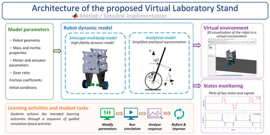
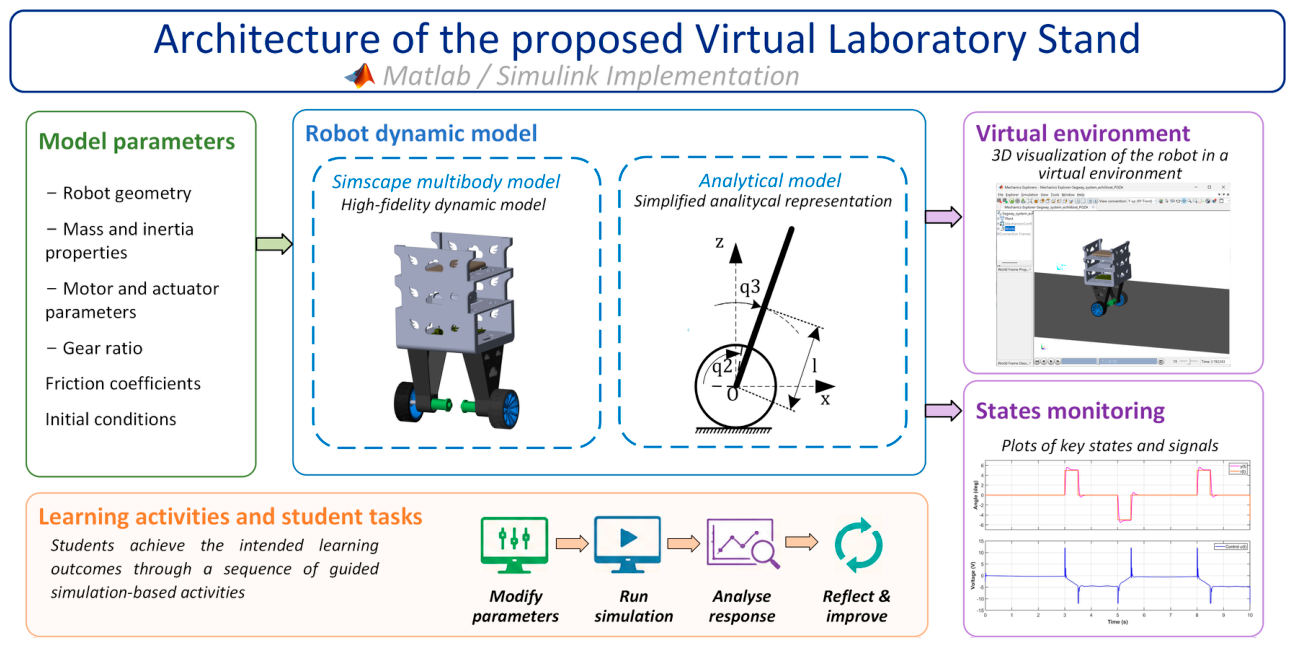
The main components of the proposed VLS are presented in Figure 1. The stand is implemented in MATLAB-Simulink R2024a and comprises two complementary models: a high-fidelity physical model developed in Simscape Multibody and an analytical model of the robot. The Simscape library allows the system to be built from interconnected blocks that mirror the structure of the real robot, including its actuators, mechanical parts, and sensors. In addition to providing a 3D virtual representation of the robot, the Simscape model enables detailed analysis of the system’s dynamic behavior. The virtual environment, visualized in Mechanics Explorer, offers a realistic representation of the robot’s motion, while Simulink facilitates real-time monitoring of the main system variables (states). The analytical model of the system, developed using the Lagrangian approach, describes its dynamics, and it is implemented in Simulink for simulation and control design.
Figure 1.
Virtual laboratory stand architecture.
Students interact with the VLS by modifying model parameters, executing simulations, analyzing the system response, and iteratively refining their solutions, thereby supporting the intended simulation-based learning activities.
The Simscape Multibody model and the analytical models, which together form the core of the proposed VLS, are presented in detail in the following subsections.
2.2.1. Simscape Multibody Model
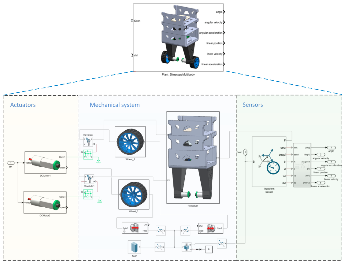
Simscape enables the development of realistic virtual models of engineering products that integrate mechanical, electrical, hydraulic, thermal, and other physical domains in a unified simulation framework, making it particularly suitable for modeling mechatronic systems (Boschetti & Sinico, 2024; Lapusan et al., 2016a). In designing the virtual model of the robot, components from the Simulink Fundamental and Multibody libraries were used. This approach helps students identify the main subsystems—such as actuators, mechanical assemblies, and sensor units—while understanding their interactions. As a result, the virtual stand matches the structure of the real system with a high degree of fidelity, making it a useful tool for both analysis and testing.
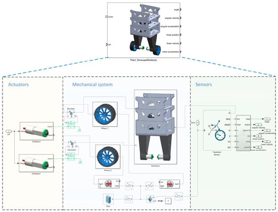
The Simscape model of the robot was created from its 3D CAD model developed in SolidWorks 2024 and imported into Simscape Multibody, enabling the development of the virtual prototype (Figure 2). In this process, the CAD assemblies’ parts and mates were automatically converted into Simulink blocks representing elements such as frames, transforms, joints, and bodies. The robot assembly consists of two main parts: wheels (housing the motor rotors) and a pendulum (main body with motor stators). The main body has triangular-shaped legs that raise the robot’s center of mass, reducing the acceleration needed for pendulum control. The robot body and the wheel components are connected through a rotational joint that allows the wheels to rotate around their axis while the main body remains free-floating, not fixed to any coordinate system. The actuation of the robot is done using two DC motors with an integrated gearbox, model IG2200019 produced by Digilent.
Figure 2.
The Simscape Multibody model of the system.
The interaction between the robot model and its virtual environment was implemented using a Sphere-to-Plane Contact Force block. In this setup, the environment is represented by a flat surface simulating the floor, and the wheels are modeled as spherical contact elements. This approach enables realistic simulation of wheel–floor interactions, capturing both normal and frictional forces during motion. The modeling approach is similar to that reported by Dosoftei et al. (2020).
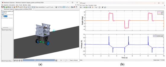
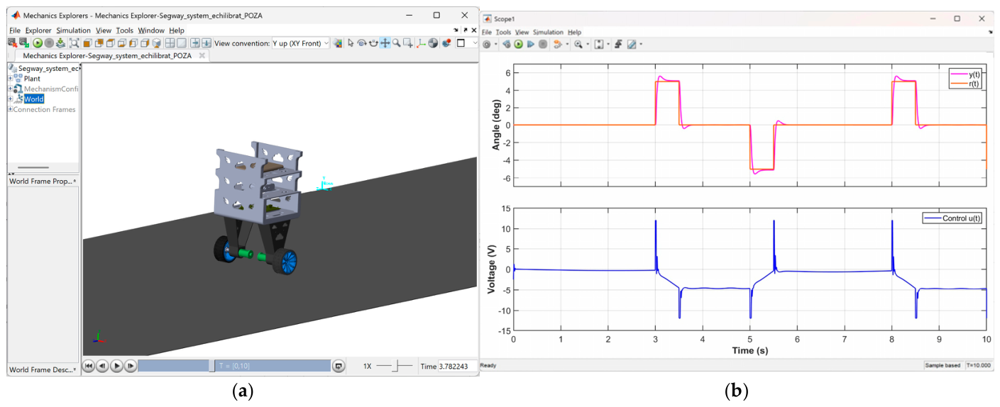
Mechanics Explorer provides 3D visualization of the robot’s behavior (Figure 3a). This offers students a realistic, life-like experience, showing how the robot responds to their developed control strategy. The changes over time of the reference input, pendulum angle, and control signals can be visualized using Simulink scope blocks (Figure 3b).
Figure 3.
Visualization of results. (a) 3D virtual environment of the robot; (b) signals displayed on scope.
The mechanical parameters, such as the mass of the pendulum, the mass of the wheels and specific moments of inertia, were determined using SolidWorks’ Mass Properties tool. These values were automatically calculated by SolidWorks based on the geometrical characteristics and the material associated with each part. The values obtained are presented in Table 1.
Table 1.
Analytical model parameters.
2.2.2. Analytical Model of the Robot
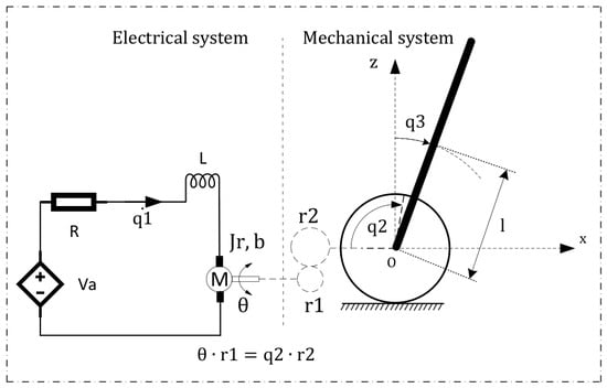
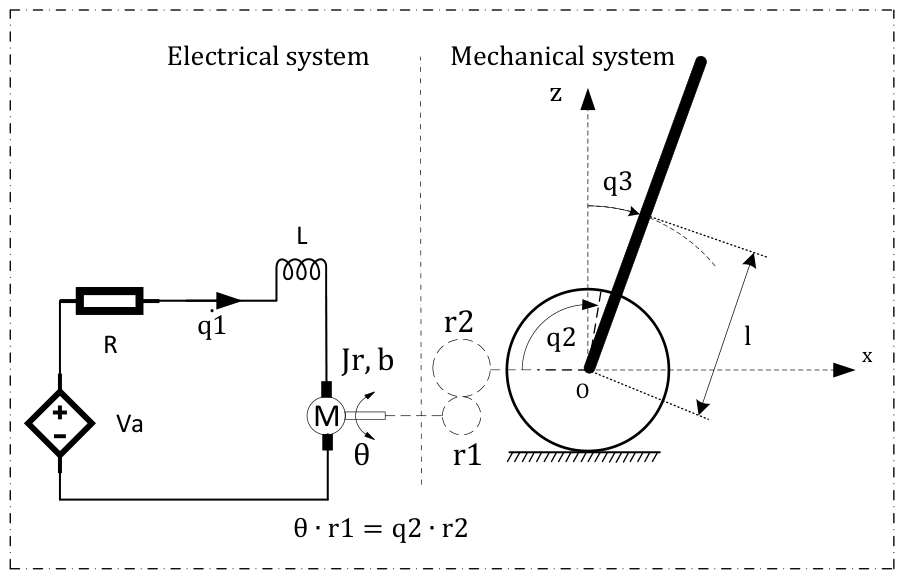
To develop the analytical model, the structure of the self-balancing Segway robot is schematically represented in Figure 4, illustrating both the electrical and mechanical components of the system. There are two identical DC motors with incorporated gearboxes attached to the wheels, as well as a pendulum (the main body). To create a representative yet pedagogically effective model of the Segway robot, a simplified approach was adopted by assuming that both wheels rotate at the same angle (rigidly connected). This assumption reduces the system’s degrees of freedom and allows the motion to be described in a linear form, making the model easier to use for teaching and analysis.
Figure 4.
The Segway system—schematic.
The Lagrangian unified formalism is used to determine the differential equation of the system. It consists of finding the system’s total kinetic and potential energy in terms of generalized coordinates: —electrical charge, —electrical current, —angular displacement of the wheels, —angular velocity of the wheels, —angular displacement of the pendulum relative to the vertical equilibrium upright position, —angular velocity of the pendulum.
The generalized Lagrange’s equation form is presented below:
The Lagrangian function is , where and V represent the system’s kinetic and potential energy. The term represents the Rayleigh dissipation function and —the generalized effort. In Table 1, all the system parameters that are utilized in the equations are presented.
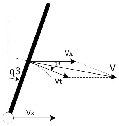
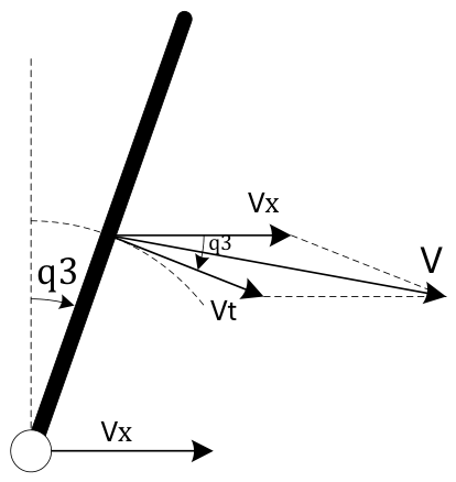
The pendulum can perform a linear motion along the x-axis and a rotation about the y-axis; its velocities are presented in Figure 5.
Figure 5.
The velocity vectors of the pendulum.
is the speed along the x-axis and is the speed from the circular motion/rotation of the pendulum.
The expression for kinetic energy is written as follows:
The expression for potential energy is presented below:
The Rayleigh dissipation function is presented below:
The generalized effort is presented below:
The equations obtained after differentiation are presented below:
The following notations were made:
The control techniques that are going to be used in this laboratory apply only to linear systems, so Equations (10)–(12) need to be linearized due to the trigonometric functions. Linearization is valid around a specific operating point, in a small region; in this case, it is the vertically upward position of the pendulum, , where is considered a small deviation from the upward equilibrium. So, the following approximations are considered:
The term has negligible values. The linearized equations that describe the system are
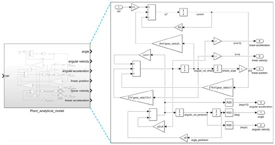
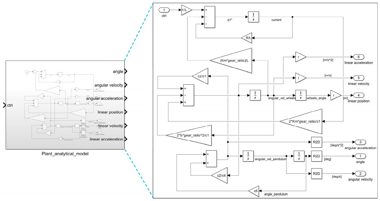
The above linear equations are represented in a Simulink model, as can be observed in Figure 6.
Figure 6.
The analytical Simulink model of the system.
2.2.3. Laboratory Tasks and Implementation Methodology
The laboratory activities were designed according to the simulation-based learning framework presented in Section 2.1 and focus on two intended LOs: (i) the ability to model and linearize mechatronic systems, and (ii) the ability to design, tune, and evaluate a PID controller. For the first LO, the students should be able to develop a mathematical model of the Segway robot (e.g., using Newtonian mechanics or Lagrangian methods), linearize the system, identify the system parameters (e.g., inertia, damping, time constants), define the inputs and outputs of the system, and identify the controlled variables. For the second LO, the students should be able to design a PID controller to maintain an upward vertical position for a self-balancing robot and apply PID tuning methods. For the designed controller, the students must assess performance based on overshoot, settling time, steady-state error, and stability.
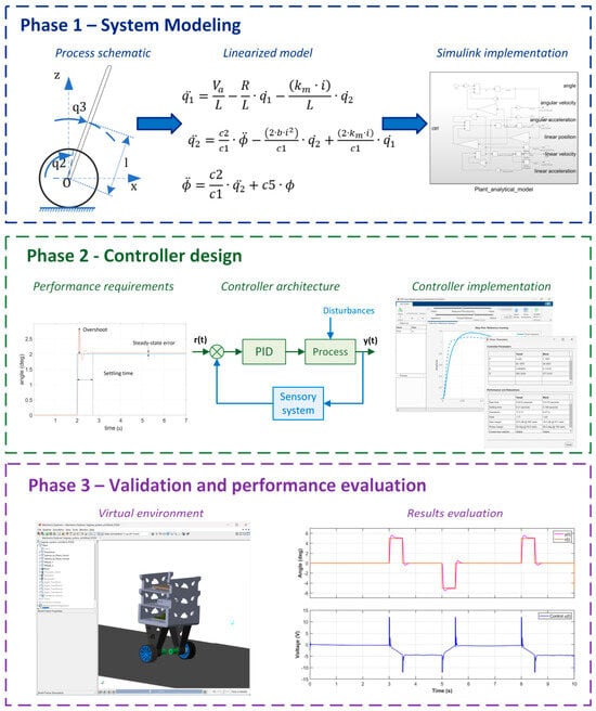
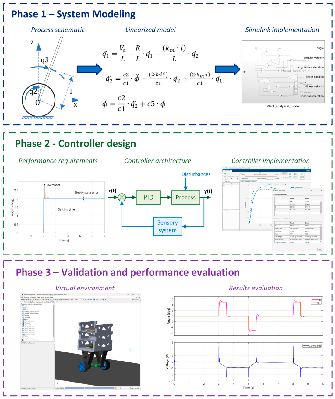
To support the achievement of these learning outcomes, the laboratory activity is organized into three sequential phases that progressively guide students from system modeling to controller design, tuning, and performance evaluation. Figure 7 illustrates the corresponding laboratory workflow.
Figure 7.
Three-phase simulation-based laboratory workflow.
The first phase focuses on developing students’ understanding of the system dynamics through mathematical modeling. Students begin by developing the dynamic equations that describe the system’s behavior. They then linearize the system around the operating point and implement the resulting linearized equations within Simulink for simulation and analysis. This activity establishes the theoretical foundation required for subsequent controller design and allows students to relate mathematical concepts to system behavior.
In the second phase, students focus on designing the controller that regulates the system’s behavior. In this example, a PID controller is used, implemented with the PID block from the Simulink Continuous Library. This block integrates a PID tuner interface that facilitates the determination of the controller parameters based on the imposed performance criteria and the adjustment of the transient time and process robustness. The students’ task is to build the Simulink model containing the reference signal, control blocks, virtual prototype, feedback system, and signal visualization blocks for the controlled parameters. They also need to consider the input signal limits by adding a saturation block. Using these simulation tools, they tune the PID parameters to achieve the imposed performance objectives. This stage promotes iterative learning by allowing students to analyze the effect of their design decisions and refine the controller accordingly.
The final phase focuses on validating the designed controller using the virtual robot model. Students test the controller’s performance by applying various inputs and disturbances. Each student is required to plot the system response y(t) compared to the reference signal r(t) and the control signal u(t) and then interpret the data from these graphs. The 3D visualization provided by Mechanics Explorer further supports conceptual understanding by enabling students to directly relate controller tuning to the dynamic behavior of the virtual robot.
3. Results and Discussions
3.1. Study Design and Data Collection
The proposed laboratory activity was implemented with third-year mechatronics students enrolled in the Advanced Control Systems course. A total of 21 students participated in the study; the sample size was determined by the number of students enrolled in the course during the study period. Students were randomly assigned to two groups: an experimental group (Group 1, n = 10) and a control group (Group 2, n = 11). Group 1 completed the simulation-based laboratory activity described in Section 2.2.3, and Group 2 performed the same learning tasks using only the analytical model. Specifically, students in Group 2 developed and linearized the mathematical model, implemented it in Simulink, designed a PID controller, and evaluated the system performance without access to the virtual Simscape model.
To evaluate the educational impact of the proposed VLS, the study investigated whether it enhances students’ perceptions of the learning experience compared with a conventional analytical-model-based laboratory activity. Specifically, it examined whether the proposed VLS (i) enhances students’ perceptions of the learning experience, (ii) improves students’ perceived achievement of the intended learning outcomes, and (iii) reveals its main strengths and limitations through students’ qualitative feedback.
After completing the activities, feedback was collected from both groups through a structured survey. The questionnaire was developed by the authors specifically for this study to evaluate students’ perceptions of the proposed laboratory activity. The questionnaire consisted of two demographic questions: Q1 (“Year of study”) and Q2 (“Type of model used: analytical only or analytical and Simscape”), five sets of closed-ended items (Q3–Q7), each organized into thematic sections and assessed using a Likert scale, and two open-ended questions (Q8 and Q9). The questionnaire provided both quantitative and qualitative data for evaluating students’ perceptions of the laboratory activity.
The reliability of the closed-ended questionnaire items (Q3–Q7) was assessed using Cronbach’s alpha. The results showed an overall α = 0.835 for Group 1 and α = 0.874 for Group 2, both above the 0.7 threshold, indicating good internal consistency of the feedback. Descriptive statistics, including the mean (M) and standard deviation (SD), were calculated for each Q3–Q7 questionnaire item. As the questionnaire responses were collected using Likert scales and the two groups were small and independent, between-group differences were evaluated using the Mann–Whitney U test. A significance level of p < 0.05 was adopted.
As the study was conducted with a single course cohort, the results should be interpreted within the limitations imposed by the sample size.
3.2. Statistical Analysis of the Questionnaire Results
Table 2 summarizes the descriptive statistics and the results of the Mann–Whitney U test for the questionnaire items (Q3–Q7). Overall, students who completed the laboratory using the proposed VLS (Group 1) reported higher mean scores for all questionnaire items than students who used only the analytical model (Group 2). Statistically significant differences (p < 0.05) were identified for Q5.1, Q6.3, and Q7.2, while the remaining items did not show statistically significant differences. The following subsections discuss these results according to the questionnaire categories.
Table 2.
Descriptive and inferential statistics for questionnaire items (Q3–Q7).
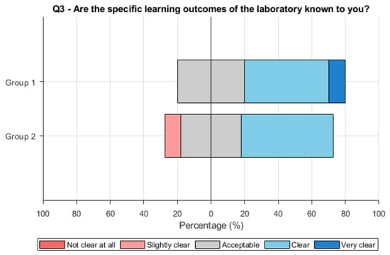
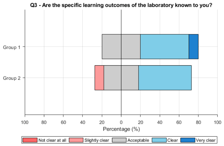
Question 3 (Q3), “Are the specific learning outcomes of the laboratory known to you?”, evaluated students’ awareness of the intended LOs associated with the laboratory activity. As shown in Figure 8, both groups reported a comparable understanding of the learning outcomes, with Group 1 obtaining a slightly higher mean score, M = 3.70 (SD = 0.67), than Group 2, M = 3.45 (SD = 0.69). However, the difference was not statistically significant (U = 63.0, p = 0.556), indicating that both groups reported a comparable understanding of the intended LOs.
Figure 8.
Feedback results on Q3.
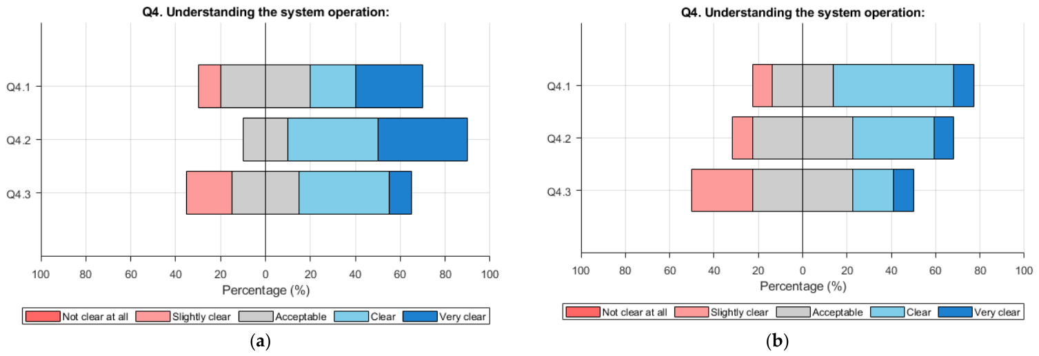
The fourth set of questions (Q4) examined students’ perception of their understanding of the system and its operation (Figure 9). For Q4.1—‘How clearly did you understand the physical and mathematical principles governing the robot’s behavior?’—Group 1 reported a mean score of M = 3.70 (SD = 1.06), while Group 2 reported a comparable mean of M = 3.64 (SD = 0.81). The difference was not statistically significant (U = 56.0, p = 0.970), indicating a similar level of perceived understanding in both groups.
Figure 9.
Feedback results on Q4: (a) Group 1; (b) Group 2.
For Q4.2—‘To what extent do you consider that the model used reflected the real behavior of a physical robot?’—Group 1 reported a higher mean of M = 4.20 (SD = 0.79) compared to Group 2 with M = 3.45 (SD = 0.82). Although this difference approached statistical significance (U = 81.0, p = 0.058), it did not reach the predefined significance level, suggesting that students using the proposed VLS tended to perceive the model as more realistic.
For Q4.3—‘Was it easy to identify the source of errors (in the simulation or the system response)?’—Group 1 reported a mean of M = 3.40 (SD = 0.97), while Group 2 reported a slightly lower mean of M = 3.09 (SD = 0.94). The difference was not statistically significant (U = 66.0, p = 0.438), indicating comparable perceptions regarding the ease of identifying error sources.
Overall, both groups reported a moderate to high understanding of the system’s physical and mathematical principles. Although Group 1 consistently reported higher mean scores, particularly for the perceived realism of the model (Q4.2), none of the differences within this category reached statistical significance.
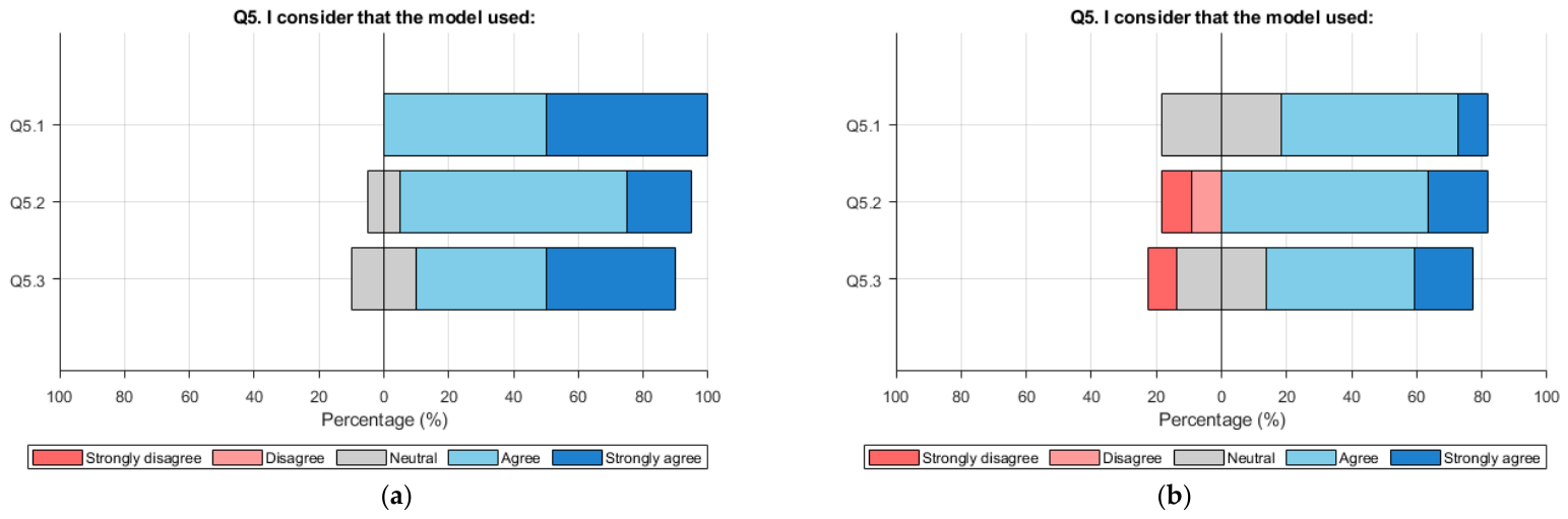
The fifth set of questions (Q5) focused on students’ perception of the educational value of the model used during the laboratory activity (Figure 10). The questions assessed whether the model was sufficiently realistic for educational purposes (Q5.1), whether it facilitated the correlation between theory and practice (Q5.2), and whether it stimulated critical thinking and system analysis (Q5.3).
Figure 10.
Feedback results on Q5: (a) Group 1; (b) Group 2.
For Q5.1—‘Was the model sufficiently realistic for educational purposes?’—Group 1 rated a significantly higher mean score, M = 4.50 (SD = 0.53), than Group 2, M = 3.73 (SD = 0.65). The difference was statistically significant (U = 87.5, p = 0.013), indicating that students using the proposed VLS perceived the model as more realistic and more suitable for supporting the learning process.
For Q5.2—‘Did the model facilitate the connection between theoretical concepts and practical application?’—Group 1 again obtained a higher mean score, M = 4.10 (SD = 0.57), than Group 2, M = 3.73 (SD = 1.19). The difference was not statistically significant (U = 60.5, p = 0.673), suggesting that both groups perceived a comparable connection between theory and practice.
For Q5.3—‘Did the model stimulate critical thinking and system analysis?’—Group 1 reported a higher mean score, M = 4.20 (SD = 0.79), than Group 2, M = 3.64 (SD = 1.12). Although students using the proposed VLS rated this aspect more positively, the difference was not statistically significant (U = 71.0, p = 0.246).
Overall, the Q5 results show that students who completed the laboratory using the proposed VLS consistently rated the educational value of the model more positively than those who used only the analytical model. Among the three questionnaire items, a statistically significant difference was observed only for the perceived realism of the model (Q5.1), while the remaining items showed similar perceptions between the two groups.
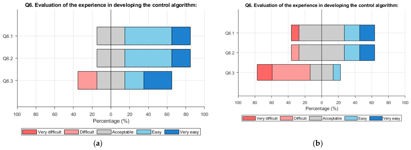
The sixth set of questions (Q6) focused on students’ perceptions of their experience in developing the control algorithm for the robot (Figure 11). The questions assessed how intuitive it was to implement the PID controller in the simulation environment (Q6.1), how clearly students were able to analyze the effect of changing the PID parameters in relation to the response of the system (Q6.2), and whether the simulation provided additional insight into the system behavior beyond that offered by the analytical model (Q6.3).
Figure 11.
Feedback results on Q6: (a) Group 1; (b) Group 2.
For Q6.1—‘How intuitive was the implementation of the PID controller?’—Group 1 reported a higher mean score of M = 3.90 (SD = 0.74) than Group 2, with an averaged M = 3.36 (SD = 1.12). The difference was not statistically significant (U = 72.0, p = 0.215), indicating comparable perceptions regarding the ease of controller implementation.
For Q6.2—‘How clearly were you able to analyse the effect of changing the PID parameters on the system response?’—Group 1 again reported a higher mean score, M = 3.90 (SD = 0.74), than Group 2, M = 3.45 (SD = 0.93). The difference was not statistically significant (U = 72.0, p = 0.215).
For Q6.3—‘Were you able to observe additional insights into the system behaviour provided by the analytical model and those provided by the simulation model?’—Group 1 reported a substantially higher mean score of M = 3.60 (SD = 1.17) than Group 2, M = 2.37 (SD = 0.90). This difference was statistically significant (U = 88.5, p = 0.016), indicating that students using the proposed VLS perceived the simulation model as providing additional insight into the system behavior beyond that obtained from the analytical model.
Overall, students who completed the laboratory using the proposed VLS consistently reported more positive experiences in implementing and analyzing the PID controller. However, a statistically significant difference was observed only for Q6.3, suggesting that the main educational advantage of the VLS was its ability to help students recognize the differences between simplified analytical models and more realistic system representations.
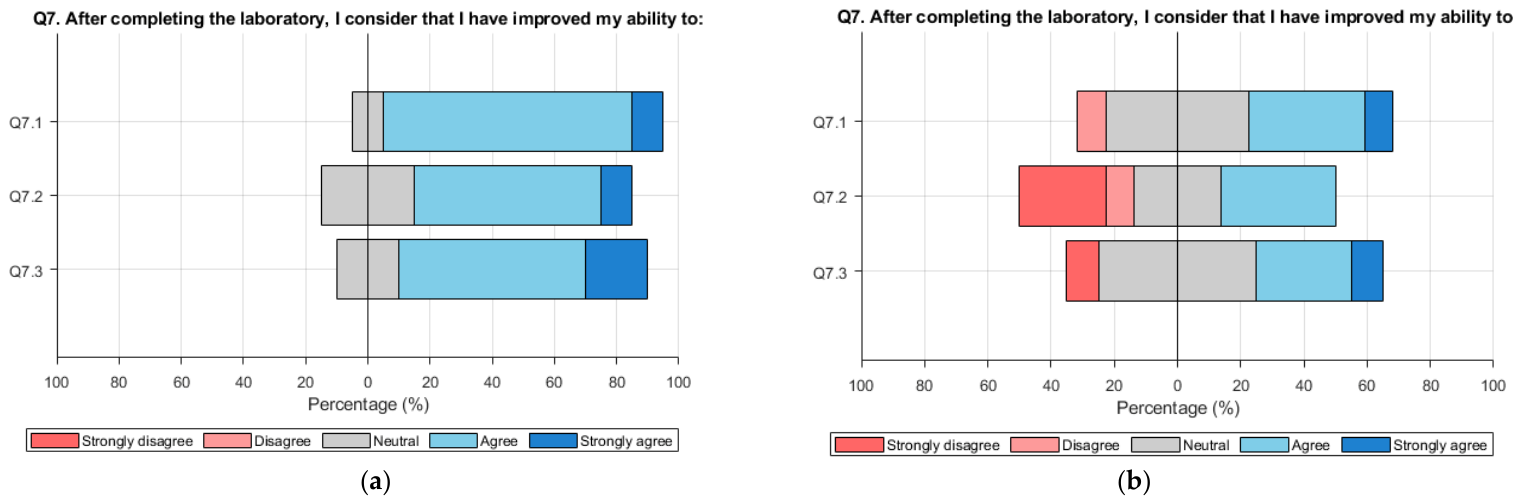
The seventh set of questions (Q7) explored students’ perceptions of the skills they developed after completing the laboratory activity (Figure 12). The questions assessed whether students felt more capable of developing and analyzing a mathematical model of a mechatronic system (Q7.1), working with simulation models of controlled processes (Q7.2), and evaluating the performance of a control system under ideal versus realistic operation conditions (Q7.3).
Figure 12.
Feedback results on Q7: (a) Group 1; (b) Group 2.
For Q7.1—‘Do you feel more capable of developing and analysing a mathematical model of a mechatronic system?’—Group 1 reported a higher mean score, M = 4.00 (SD = 0.47), compared to Group 2, M = 3.45 (SD = 0.82). The difference was not statistically significant (U = 78.0, p = 0.075), indicating comparable perceptions regarding the development and analysis of mathematical models.
For Q7.2—‘Do you feel more capable of working with simulation models of controlled processes?’—Group 1 again reported a higher mean score, M = 3.80 (SD = 0.63), than Group 2, M = 2.73 (SD = 1.27). This difference was statistically significant (U = 81.5, p = 0.049), indicating that students using the proposed VLS perceived a greater improvement in their ability to work with simulation models of controlled processes.
For Q7.3—’Do you feel more capable of evaluating the performance of a control system under ideal and realistic operating conditions?’—Group 1 reported a higher mean score, M = 4.00 (SD = 0.67), than Group 2, M = 3.36 (SD = 1.03). Although Group 1 rated this aspect more positively, the difference was not statistically significant (U = 76.0, p = 0.118).
Overall, students who completed the laboratory using the proposed VLS consistently reported greater improvements in the evaluated competencies. However, a statistically significant difference was observed only for Q7.2, suggesting that the main educational benefit of the VLS in this category was improving students’ confidence in working with simulation models of controlled processes.
3.3. Qualitative Feedback
In the open question Q8—“What did you enjoy most about the lab?”—students from Group 1 mentioned (selection): “That I was able to work on a model that is also visual. I was able to see exactly on the virtual model how changing the controller affects the system’s response.”, “The more detailed Simscape part”, “Robot simulation” or “It was quite intuitive”. From Group 2, the feedback was (selection) as follows: “Observing the differences obtained by varying the values of Kp, Ki, and Kd” or “The complexity of the system modeled”. It can be observed that Group 1’s feedback emphasized the value of visual and intuitive simulation tools, while Group 2 highlighted the analytical aspects of parameter variation and system complexity.
For question Q9—“What would you suggest for improving the structure of the laboratory or the models used?”—students from Group 1 responded (selection) as follows: “I would suggest placing more emphasis on the practical part.”, “More details on integrating the CAD parts into the model” or “I have no suggestion to add”. From Group 2, the replies were (selection) as follows: “To work with more physical models.”, “It would be good to also implement the Simscape component, to make it more engaging and of broader interest”, “I believe that directly visualizing the results in Simscape or in a real model would be more beneficial for understanding the problem” or “Emphasizing the differences in behavior with different values of Kp, Ki, Kd”. Overall, the qualitative feedback indicates that Group 1 primarily suggested refinements to the existing laboratory activities, whereas Group 2 more frequently expressed interest in incorporating simulation-based and visual modeling approaches. These comments complement the quantitative findings by highlighting students’ appreciation of interactive and visually supported learning experiences.
3.4. Discussion
The results suggest that students who completed the laboratory using the proposed VLS generally reported more positive perceptions of the laboratory experience, the educational value of the simulation model, and the competencies developed during the activity than students who worked only with the analytical model. Although higher mean scores were consistently observed for Group 1 across all questionnaire categories, statistically significant differences were identified only for the perceived realism of the model (Q5.1), the additional insight provided by the simulation beyond the analytical model (Q6.3), and students’ confidence in working with simulation models of controlled processes (Q7.2).
The qualitative feedback further supports these findings. Students using the proposed VLS emphasized the benefits of the visual and interactive simulation environment, particularly its ability to facilitate understanding of the relationship between controller tuning and system behavior. In contrast, several students from Group 2 suggested incorporating simulation-based models and enhanced visualization features, indicating that these elements were perceived as valuable additions to the laboratory activity.
From an educational perspective, the proposed VLS can be integrated into undergraduate control systems and mechatronics courses either as a complement to traditional laboratory activities or as an alternative when access to physical laboratory equipment is limited. The developed methodology can also be adapted to other engineering systems and control applications by replacing the simulated process while preserving the same simulation-based learning framework.
In addition to its educational benefits, the proposed VLS offers practical advantages for laboratory teaching. By reducing the dependence on dedicated physical laboratory equipment, it can lower implementation and maintenance costs while minimizing disruptions caused by hardware failures or limited equipment availability, making it both a pedagogically and logistically effective solution.
While the educational evaluation was based primarily on students’ perceptions collected through questionnaires, it provided valuable insights into the perceived educational value of the proposed VLS. Future studies should complement these findings with objective measures of learning performance, such as pre- and post-tests, laboratory assessments, or performance-based evaluations, to provide a more comprehensive assessment of its educational effectiveness.
4. Conclusions
The paper presented a VLS for teaching control design in mechatronics that combines an analytical model with a high-fidelity Simscape-based model of a Segway robot. The platform enables students to model system dynamics, design and tune PID controllers, and directly link control strategies to system behavior through visual feedback. The VLS allows students to perform a range of experiments and analyze system performance while focusing on control design rather than hardware-related issues.
As part of the evaluation of the VLS, the proposed laboratory activity was implemented with 21 third-year students, divided into a control group that used only the analytical model and an experimental group that followed the simulation-based approach. The comparative evaluation of students’ feedback revealed that the VLS group reported ratings that were approximately 15% higher for the perceived development of competencies, confidence in designing and testing control algorithms, and the perceived realism of the simulation model. Students particularly appreciated the virtual prototype’s ability to visualize the relationship between controller parameters and system behavior. Moreover, the VLS has the potential to reduce the logistical and maintenance challenges typically encountered with physical laboratory stands.
Overall, the study indicates that the proposed VLS provides a promising and resource-efficient environment for teaching control system design in mechatronics. Although the evaluation involved a single course cohort, the results indicate that the VLS was well received by students and supported the intended LOs. The positive student perceptions further suggest that the simulation-based learning approach helped students interpret the effects of controller tuning through direct interaction with the simulated system. Future studies involving larger cohorts should examine whether these findings can be reproduced and complement the current perception-based evaluation with objective measures of learning, such as pre- and post-tests, laboratory assessments, and examination results. Future developments of the VLS will include more complex operating scenarios and advanced control methods, including state-space control and LQR, to support additional topics in control engineering.
Author Contributions
Conceptualization, C.L. and I.P.; methodology, C.L.; software, I.P.; validation, I.P., D.G. and C.L.; formal analysis, I.P.; investigation, I.P. and D.G.; resources, I.P. and C.L.; writing—original draft preparation, I.P., D.G. and C.L.; writing—review and editing, I.P., D.G. and C.L.; visualization, I.P. and C.L.; supervision, C.L.; project administration, C.L.; funding acquisition, I.P. and C.L. All authors have read and agreed to the published version of the manuscript.
Funding
This research received no external funding.
Institutional Review Board Statement
Ethical review and approval were waived for this study (“Development of a virtual laboratory stand using Simscape for mechatronic engineering education”), as the research did not involve experiments with humans, animals, or sensitive personal data. The activities described were part of regular educational laboratory work within the Advanced Control Systems course at the Technical University of Cluj-Napoca and were carried out in full compliance with the institution’s internal regulations, as well as applicable international and European Union regulations on research ethics.
Informed Consent Statement
Informed consent was obtained from all participants involved.
Data Availability Statement
The original contributions presented in this study are included in the article. Further inquiries can be directed to the corresponding author.
Acknowledgments
The authors gratefully acknowledge the technical and financial support provided by the Technical University of Cluj-Napoca for the research presented in this paper, as well as the support provided by the Intelligent Mechatronic Systems Laboratory (IMSLab) in carrying out the research activities.
Conflicts of Interest
The authors declare no conflicts of interest.
Abbreviations
The following abbreviations are used in this manuscript:
| VLS | Virtual Laboratory Stand |
| PID | Proportional–Integrative–Derivative |
| GUI | Graphical User Interface |
| LQR | Linear Quadratic Regulator |
| SVFC | Space Vector Field Control |
| LOs | Learning Outcomes |
References
- Amirkhani, S., & Nahvi, A. (2016). Design and implementation of an interactive virtual control laboratory using haptic interface for undergraduate engineering students. Computer Applications in Engineering Education, 24(4), 508–518. [Google Scholar] [CrossRef] [Scilit]
- Asgari, S., Trajkovic, J., Rahmani, M., Zhang, W., Lo, R., & Sciortino, A. (2021). An observational study of engineering online education during the COVID-19 pandemic. PLoS ONE, 16(4), e 0250041. [Google Scholar] [CrossRef] [Scilit] [PubMed]
- Álvarez-Siordia, F. M., Merino-Soto, C., Rosas-Meléndez, S. A., Pérez-Díaz, M., & Chans, G. M. (2025). Simulators as an innovative strategy in the teaching of physics in higher education. Education Sciences, 15(2), 131. [Google Scholar] [CrossRef] [Scilit]
- Bergamo, P. A. D. S., Streng, E. S., de Carvalho, M. A., Rosenkranz, J., & Ghorbani, Y. (2022). Simulation-based training and learning: A review on technology-enhanced education for the minerals industry. Minerals Engineering, 175, 107272. [Google Scholar] [CrossRef] [Scilit]
- Boschetti, G., & Sinico, T. (2024). Designing digital twins of robots using Simscape multibody. Robotics, 13(4), 62. [Google Scholar] [CrossRef] [Scilit]
- Boubaker, O. (2012). The inverted pendulum: A fundamental benchmark in control theory and robotics. In International conference on education and e-learning innovations (pp. 1–6). IEEE. [Google Scholar] [CrossRef] [Scilit]
- Chernikova, O., Heitzmann, N., Stadler, M., Holzberger, D., Seidel, T., & Fischer, F. (2020). Simulation-based learning in higher education: A meta-analysis. Review of Educational Research, 90(4), 499–541. [Google Scholar] [CrossRef] [Scilit]
- Crawley, E. F., Malmqvist, J., Östlund, S., Brodeur, D. R., & Edström, K. (2014). The CDIO approach. In Rethinking engineering education: The CDIO approach (pp. 11–45). Springer International Publishing. [Google Scholar] [CrossRef] [Scilit]
- De Jong, T., Linn, M., & Zacharia, Z. (2013). Physical and virtual laboratories in science and engineering education. Science, 340(6130), 305–308. [Google Scholar] [CrossRef] [Scilit] [PubMed]
- Dosoftei, C., Horga, V., Doroftei, I., Popovici, T., & Custura, Ş. (2020). Simplified mecanum wheel modelling using a reduced omni wheel model for dynamic simulation of an omnidirectional mobile robot. In 2020 International Conference and Exposition on Electrical and Power Engineering (EPE) (pp. 721–726). IEEE. [Google Scholar] [CrossRef] [Scilit]
- Faulconer, E. K., & Gruss, A. B. (2018). A review to weigh the pros and cons of online, remote, and distance science laboratory experiences. International Review of Research in Open and Distributed Learning, 19(2), 155–168. [Google Scholar] [CrossRef] [Scilit]
- Feijoo-Garcia, M. A., Holstrom, M. S., Magana, A. J., & Newell, B. A. (2024). Simulation-based learning and argumentation to promote informed design decision-making processes within a first-year engineering technology course. Sustainability, 16(7), 2633. [Google Scholar] [CrossRef] [Scilit]
- García-Alberti, M., Suárez, F., Chiyón, I., & Mosquera Feijoo, J. (2021). Challenges and experiences of online evaluation in courses of civil engineering during the lockdown learning due to the COVID-19 pandemic. Education Sciences, 11(2), 590. [Google Scholar] [CrossRef] [Scilit]
- Guajardo-Cuéllar, A., Corona-Echauri, R., Meza-Flores, R. A., Vázquez, C. R., Rodríguez-Arreola, A., & Navarro-Gutiérrez, M. (2025). Mixed reality laboratory for teaching control concepts: Design, validation, and implementation. Education Sciences, 15(7), 883. [Google Scholar] [CrossRef] [Scilit]
- Hasan, H., Wulansari, R. E., Maksum, H., & Putri, T. T. A. (2024). Investigating the impacts of a simulation-based learning model using simulation virtual laboratory on engineering students. Sinkron: Jurnal dan Penelitian Teknik Informatika, 8(3), 1569–1576. [Google Scholar] [CrossRef] [Scilit]
- Hong, B., & Ghanavati, A. (2022, April 22–23). The virtual laboratory: A natural vehicle for simulation in engineering education. ASEE-NE 2022, ASEE Conference, Boston, MA, USA. [Google Scholar] [CrossRef] [Scilit]
- Kebande, V. R. (2024). The impact of virtual laboratories on active learning and engagement in cybersecurity distance education. arXiv, arXiv:2404.04952. [Google Scholar]
- Kefalis, C., Skordoulis, C., & Drigas, A. (2025). Digital simulations in STEM education: Insights from recent empirical studies, a systematic review. Encyclopedia, 5, 10. [Google Scholar] [CrossRef] [Scilit]
- Khan, S., Jaffery, M. H., Hanif, A., & Asif, M. R. (2017). Teaching tool for a control systems laboratory using a quadrotor as a plant in MATLAB. IEEE Transactions on Education, 60(4), 249–256. [Google Scholar] [CrossRef] [Scilit]
- Lampropoulos, G., Fernández-Arias, P., de Bosque, A., & Vergara, D. (2025). Virtual reality in engineering education: A scoping review. Education Sciences, 15(8), 1027. [Google Scholar] [CrossRef] [Scilit]
- Lapusan, C., Balan, R., Hancu, O., & Plesa, A. (2016a). Development of a multi-room building thermodynamic model using Simscape library. Energy Procedia, 85, 320–328. [Google Scholar] [CrossRef] [Scilit]
- Lapusan, C., Hancu, O., Rad, C., Dache, L., & Maties, V. (2016b). Integrated learning platform based on Lego NXT and Matlab for teaching mechatronics. In 2016 8th international conference on electronics, computers and artificial intelligence (ECAI) (pp. 1–4). IEEE. [Google Scholar] [CrossRef] [Scilit]
- Li, J., & Liang, W. (2024). Effectiveness of virtual laboratory in engineering education: A meta-analysis. PLoS ONE, 19(12), e0316269. [Google Scholar] [CrossRef] [Scilit] [PubMed]
- Luan, T. (2024). A comprehensive review of simulation technology: Development, methods, applications, challenges and future trends. International Journal of Emerging Technologies and Advanced Applications, 1(5), 9–14. [Google Scholar] [CrossRef] [Scilit]
- National Research Council. (2006). America’s lab report: Investigations in high school science. National Academy Press. [Google Scholar]
- Negahban, A. (2024). Simulation in engineering education: The transition from physical experimentation to digital immersive simulated environments. Simulation, 100(7), 695–708. [Google Scholar] [CrossRef] [Scilit]
- Potkonjak, V., Vukobratović, M., Jovanović, K., & Medenica, M. (2010). Virtual mechatronic/robotic laboratory—A step further in distance learning. Computers & Education, 55(2), 465–475. [Google Scholar] [CrossRef] [Scilit]
- Renganayagalu, S. K., Mallam, S., Nazir, S., Ernstsen, J., & Haavardtun, P. (2019). Impact of simulation fidelity on student self-efficacy and perceived skill development in maritime training. TransNav: International Journal on Marine Navigation and Safety of Sea Transportation, 13(3), 663–669. [Google Scholar] [CrossRef] [Scilit]
- Schnieder, M., Williams, S., & Ghosh, S. (2022). Comparison of in-person and virtual labs/tutorials for engineering students using blended learning principles. Education Sciences, 12(3), 153. [Google Scholar] [CrossRef] [Scilit]
- Shambare, B., & Jita, T. (2025). A new era of learning: Exploring science teachers’ perceptions of virtual lab in rural schools. Education and Information Technologies, 30, 15185–15205. [Google Scholar] [CrossRef] [Scilit]
- Stefanova, T. (2022). Engineering education standards. Yearbook Telecommunications, 9, 79–86. [Google Scholar] [CrossRef] [Scilit]
- Terkaj, W., Urgo, M., Kovács, P., Tóth, E., & Mondellini, M. (2024). A framework for virtual learning in industrial engineering education: Development of a reconfigurable virtual learning factory application. Virtual Reality, 28(3), 148. [Google Scholar] [CrossRef] [Scilit]
- Tsirulnikov, D., Suart, C., Abdullah, R., Vulcu, F., & Mullarkey, C. E. (2023). Game on: Immersive virtual laboratory simulation improves student learning outcomes & motivation. FEBS Open Bio, 13(3), 396–407. [Google Scholar] [CrossRef] [Scilit] [PubMed]
- Usman, M., & Huda, K. (2021). Virtual lab as distance learning media to enhance student’s science process skill during the COVID-19 pandemic. In Journal of physics: Conference series (Vol. 1882, p. 012126). IOP Publishing. [Google Scholar] [CrossRef] [Scilit]
- Van den Beemt, A., Groothuijsen, S., Ozkan, L., & Hendrix, W. (2023). Remote labs in higher engineering education: Engaging students with active learning pedagogy. Journal of Computing in Higher Education, 35, 320–340. [Google Scholar] [CrossRef] [Scilit] [PubMed]
- Van der Velden, A. (2017). High-fidelity simulation surrogate models for systems engineering. In Disciplinary convergence in systems engineering research (pp. 327–339). Springer International Publishing. [Google Scholar] [CrossRef] [Scilit]
- Vergara, D., Fernández-Arias, P., Extremera, J., Dávila, L. P., & Rubio, M. P. (2022). Educational trends post COVID-19 in engineering: Virtual laboratories. Materials Today: Proceedings, 49, 155–160. [Google Scholar] [CrossRef] [Scilit] [PubMed]
- Yao, J. F., Yang, Y., Wang, X. C., & Zhang, X. P. (2023). Systematic review of digital twin technology and applications. Visual Computing for Industry, Biomedicine, and Art, 6(1), 10. [Google Scholar] [CrossRef] [Scilit] [PubMed]
- Zawacki-Richter, O., & Bozkurt, A. (2022). Research trends in open, distance, and digital education. In Handbook of open, distance and digital education (pp. 1–23). Springer. [Google Scholar] [CrossRef] [Scilit]

Disclaimer/Publisher’s Note: The statements, opinions and data contained in all publications are solely those of the individual author(s) and contributor(s) and not of MDPI and/or the editor(s). MDPI and/or the editor(s) disclaim responsibility for any injury to people or property resulting from any ideas, methods, instructions or products referred to in the content. |
© 2026 by the authors. Licensee MDPI, Basel, Switzerland. This article is an open access article distributed under the terms and conditions of the Creative Commons Attribution (CC BY) license.