


Abstract
Concentrated solar power systems can provide dispatchable renewable energy, but their application in distributed cogeneration is constrained by high costs and thermal losses associated with indirect heat transfer. This study proposes a direct vapour generation cascade organic Rankine cycle (DVG-CORC) for combined heat and power production. A biphenyl–diphenyl oxide (BDO) mixture is used as both the solar-collection fluid and the high-temperature cycle working fluid, while thermal storage and four operating modes are incorporated to accommodate variations in solar irradiance and enable continuous operation. Thermodynamic and economic models are developed to evaluate system performance under different evaporation and condensation temperatures. At an evaporation temperature of 400 °C, the maximum thermal efficiencies are 37.67%, 35.38%, and 33.11% at condensation temperatures of 60 °C, 80 °C, and 100 °C, respectively. At a condensation temperature of 60 °C, the cogeneration system generates an estimated annual revenue of USD 929,637, which is USD 284,269 higher than that of the power-generation-only configuration operating at a condensation temperature of 30 °C. These results demonstrate that direct vapour generation, cascade energy utilization, and heat recovery can improve the thermodynamic and economic performance of distributed solar cogeneration systems.
1. Introduction
Concentrated solar power (CSP), as a vital solar energy utilization technology, possesses unique technical advantages and significant development potential [1]. Unlike photovoltaic (PV) power generation, which directly converts light energy into electricity, CSP systems convert concentrated solar energy into high-temperature thermal energy and subsequently utilize a thermodynamic cycle for electricity generation [2]. Equipped with thermal energy storage systems, CSP can store heat collected during the day and continuously generate electricity during nighttime or cloudy weather, achieving stable and dispatchable power output [3]. CSP systems can achieve long-duration energy storage (typically 6–15 h) through thermal storage, which is a large-scale energy storage solution [4]. This is currently an economically challenging feat for PV systems using electrochemical storage. CSP systems employ turbine generators similar to those used in conventional thermal power plants, improving the stability of the power grid [5]. Additionally, the high-temperature heat generated by CSP can be used not only for power generation but also for other applications. The efficient utilization of solar energy relies on the conversion of incident solar radiation into thermal energy through solar absorption and photothermal conversion processes [6]. Solar thermal energy has been investigated for industrial process heating [7] and seawater desalination [8], while solar-driven cogeneration systems have also been widely studied for the simultaneous production of heat, freshwater, and power [9], thereby demonstrating the potential for cascading energy utilization.
However, the most significant challenge facing CSP is its relatively high power-generation cost [10]. The levelized cost of energy (LCOE) for CSP is currently significantly higher than that of PV power generation [11]. This is mainly due to the complexity of CSP systems and their high initial capital requirements, as the majority of the investment is associated with key infrastructure, including the solar-collection field and thermal storage units. Although large-scale centralized CSP plants are highly efficient, they require substantial initial investment and extensive land for solar collection, limiting their widespread adoption. Distributed combined heat and power systems represent one effective pathway to reduce CSP costs. Distributed CSP systems do not require large-scale solar-collection sites and can be flexibly integrated with industrial parks, villages, towns, and other end-users [12,13]. By utilizing energy storage systems to adjust power output, they effectively address the intermittency of solar power generation [14]. This flexibility significantly reduces project siting difficulties and transmission costs. Moreover, through cogeneration, the comprehensive energy efficiency of CSP systems can be markedly improved [15]. Building on these advantages, distributed solar energy systems have increasingly been studied for meeting multiple local energy demands. Solar ORC systems have been investigated for cogeneration and industrial process applications [16], while different configurations and operating modes of solar-driven cogeneration systems have been analyzed using various collector technologies [17]. In addition, the economic potential of distributed energy generation has been systematically reviewed in the literature [18]. These studies provide a basis for the further development of solar ORC-based cogeneration systems. Zhang et al. [19] investigated a solar-driven transcritical organic Rankine cycle coupled with a transcritical CO2 refrigeration cycle and conducted a comprehensive evaluation considering thermodynamic, environmental, safety, and techno-economic indicators. Their study confirmed the feasibility of solar ORC technologies in achieving combined electricity generation and cooling provision. Pina et al. [20] designed a CSP-driven parabolic-trough–ORC cogeneration system for a commercial centre. By coupling concentrated solar thermal energy with an ORC-based configuration, the proposed system could simultaneously provide electricity and useful thermal energy, demonstrating the application potential of CSP-driven cogeneration in distributed energy systems. From the heat-utilization perspective, Boyko et al. [21] proposed an intelligent active individual heating point for buildings connected to third-generation centralized heating systems. The proposed system employs adaptive regulation and a local thermal-energy source to improve heat-supply reliability and indoor thermal comfort, providing a potentially useful end-use framework for the thermal energy supplied by CSP cogeneration systems. Jensen et al. [22] analyzed a renewable energy configuration deployed in Brønderslev, Denmark, integrating solar thermal technology with biomass utilization to achieve combined heat and power generation. The plant integrates a 16.6 MW parabolic-trough solar collector field and utilizes heat from the power-generation system to supply the local district-heating network, demonstrating the practical feasibility of combining CSP generation with large-scale useful heat production.
Currently, conventional CSP systems typically employ the steam Rankine cycle. However, this system faces significant challenges in small-scale distributed applications. Due to the high latent heat of water, low-power steam turbines present technical difficulties and low efficiency, making them unsuitable for cogeneration. In contrast, due to the excellent thermal properties of organic working fluids, the organic Rankine cycle (ORC) system has greater potential for application in the solar cogeneration field [23]. Mariñes Delgado et al. [24] evaluated different ORC integration configurations for recovering exhaust-gas and mill-steam heat in a sugar plant, demonstrating the potential of ORC technology to alleviate industrial cogeneration deficits and improve overall energy utilization. Pina et al. [25] comparatively designed two parabolic-trough solar ORC cogeneration plants for a commercial centre and evaluated their technical, economic, and environmental feasibility for supplying electricity and cooling. Their study demonstrated the application potential of CSP-driven ORC cogeneration in distributed commercial energy systems. Rahmdel et al. [26] investigated a solar-assisted ORC configuration for remote-area applications, providing multiple energy outputs under variable operating scenarios. The system was designed to respond to variations in environmental conditions while simultaneously providing electricity, freshwater, and high-temperature heating energy. Building on these direct solar-driven configurations, Wang et al. [27] developed a hybrid solar–waste energy plant integrating a parabolic-trough collector with an ORC. In this configuration, waste-incineration heat supplements the solar heat input to mitigate solar intermittency, while enabling the cogeneration of electrical power and valuable thermal energy for district-heating applications. Subsequently, the system was optimized through a multi-objective framework considering both energetic effectiveness and economic viability. Currently, most solar ORC systems operate at evaporation temperatures below 300 °C, with the majority of research focused on low- and medium-temperature heat sources due to the critical temperature limitations of organic working fluids [28]. Furthermore, traditional ORC systems employ indirect heat exchange methods, which involve heat transfer temperature differences and associated losses, limiting the system’s thermal-to-power conversion efficiency [29]. Therefore, the development of high-temperature solar ORC systems that can reduce intermediate heat-transfer losses while enabling efficient cascade utilization of the remaining thermal energy is still worthy of further investigation.
To overcome these limitations, the proposed cogeneration configuration directly couples the solar field with a high-temperature ORC. BDO circulates through both units, receiving solar energy in the collector field before entering the top cycle as its working fluid. This arrangement removes the need for an intermediate heat-transfer loop and consequently reduces the temperature drop associated with indirect heating while simplifying the system configuration. The thermal stability and relatively low viscosity of BDO make it suitable for operation over a wide temperature range of approximately 12–400 °C [30]. Operation at an elevated evaporation temperature also increases the temperature level available for power production and subsequent heat recovery. Previous studies have demonstrated the feasibility of using BDO in direct vapour generation solar ORC systems for power generation [31]. Building on this previous work, the present study further integrates BDO-based direct vapour generation with a cascade ORC, thermal energy storage, multiple irradiation-dependent operating modes, and useful heat recovery to achieve combined heat and power generation. Accordingly, the main contribution of this study lies in integrating high-temperature direct vapour generation, cascade energy utilization, thermal storage, and cogeneration within a unified solar ORC framework.
Therefore, an efficient direct vapour generation cascade organic Rankine cycle (DVG-CORC) system for cogeneration is presented. The BDO mixture is applied to the solar collector field and CORC system as a heat-collecting medium and a power-generating medium, respectively. When BDO absorbs heat in the collection field and reaches the evaporation temperature of CORC, it enters the CORC system to drive the system to generate power. Combined with the fluctuating trend of solar radiation, different operating modes are designed, and a thermal storage device is added. When the solar radiation intensity is weak, the thermal storage device releases heat to drive the system to operate, improving the power generation of the system. The overall performance of this new BDO-based DVG-CORC system has been studied. Furthermore, an annual economic assessment is conducted by comparing the proposed cogeneration system with a corresponding power-generation-only DVG-CORC configuration under the same climatic conditions. This novel high-temperature DVG-CORC cogeneration system is anticipated to enhance the overall performance and economic viability of solar-based cogeneration technologies, promoting the development and application of distributed solar energy systems.
2. System Description
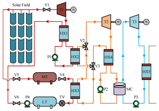
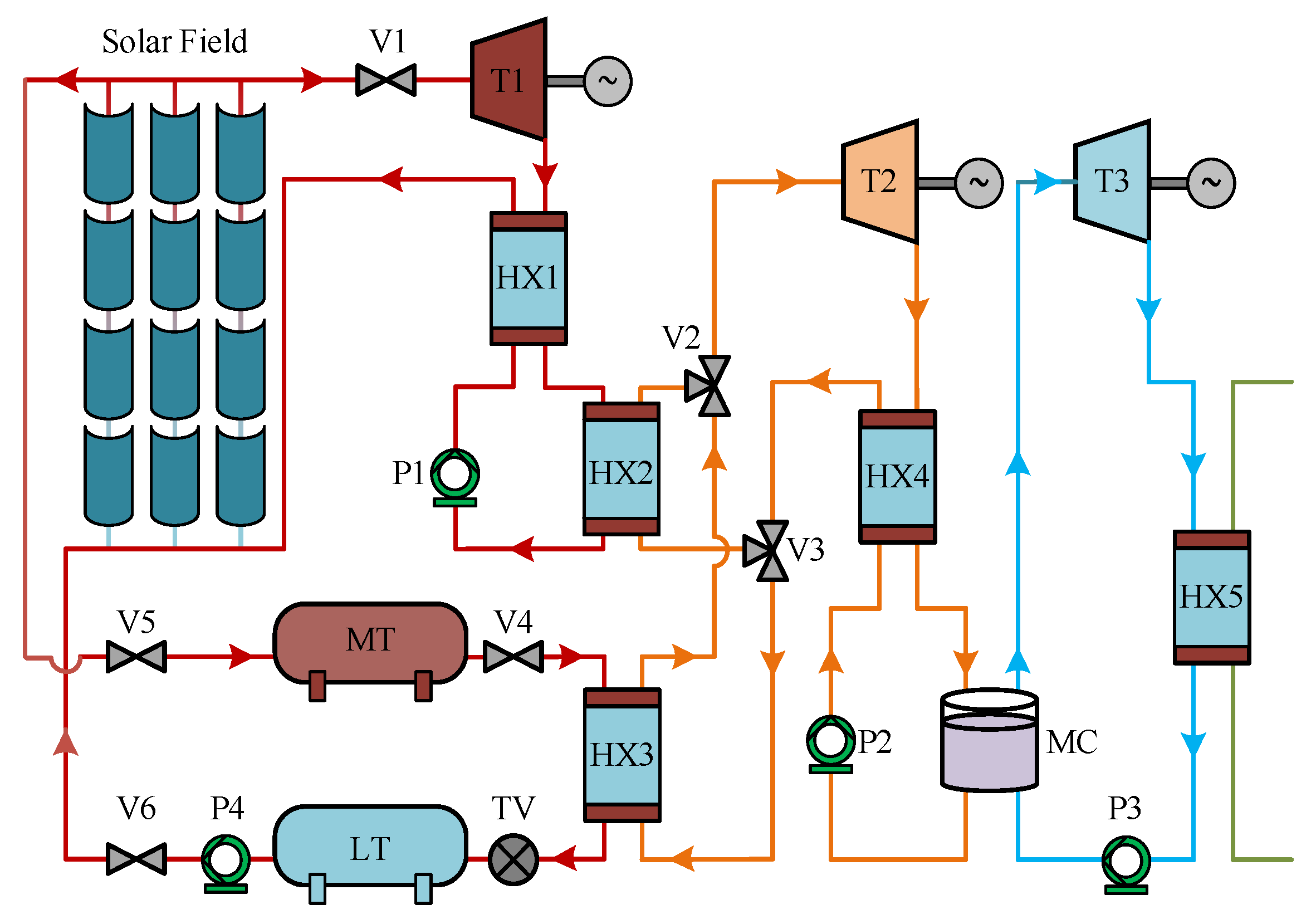
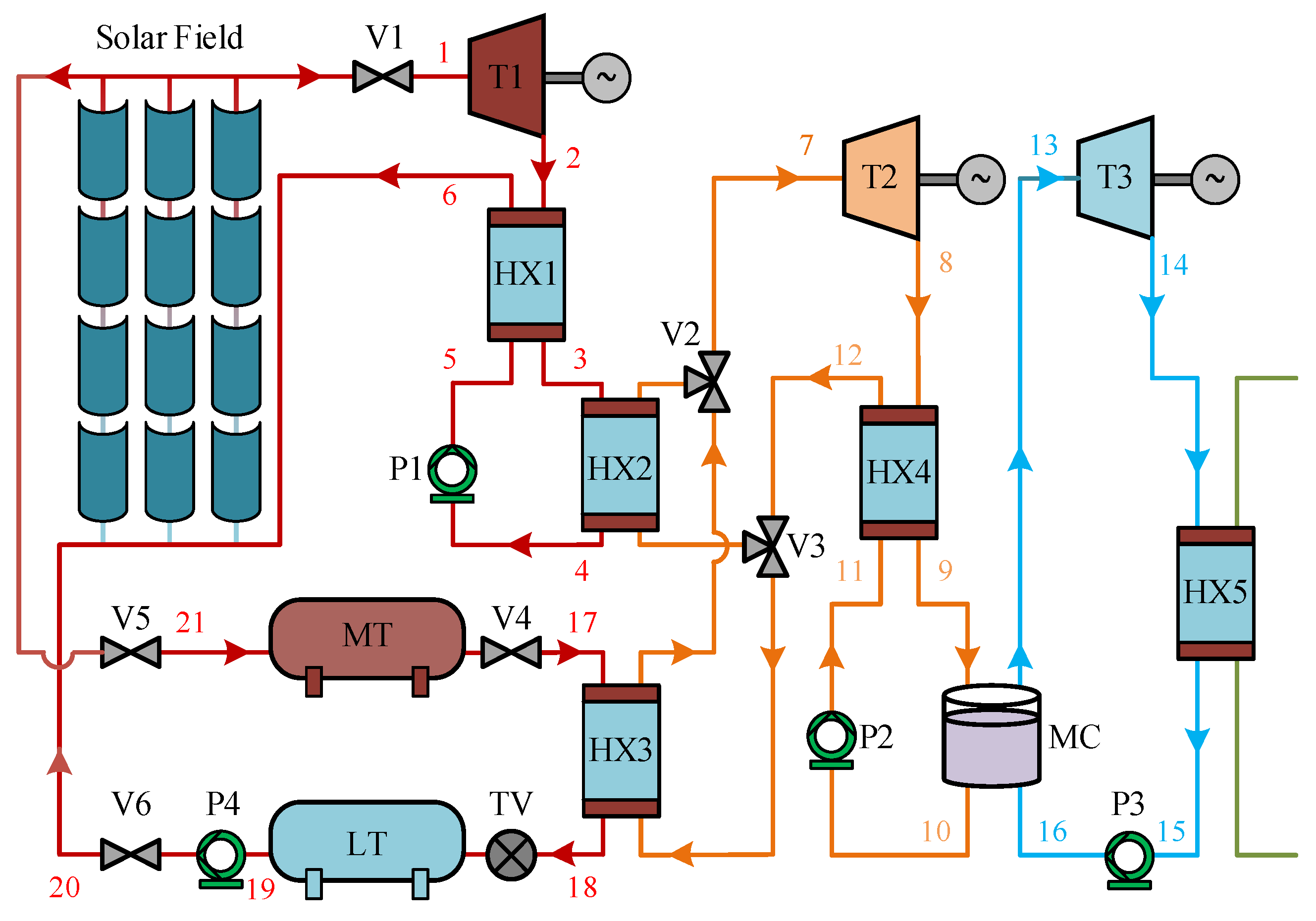
Figure 1 presents the proposed system, which consists of a solar-collection field, a thermal-storage subsystem, and a cascade ORC. Parabolic-trough or Fresnel technologies can be adopted for the solar field. BDO circulates directly between the solar field and the top ORC, thereby serving simultaneously as the solar-collection medium and the high-temperature working fluid. After absorbing solar energy and reaching the required evaporation state, the BDO vapour expands through T1 to generate power. The thermal energy remaining in the turbine exhaust is subsequently transferred to the bottom cycle through HX2. In this way, the bottom ORC further converts the residual medium-temperature energy of the top cycle into electricity, while HX3 also allows part of the lower-temperature energy to be recovered for useful heat supply. Thermal storage is provided by the medium-temperature tank (MT) and low-temperature tank (LT). Under insufficient solar input, BDO is discharged from MT to LT and supplies heat to the bottom ORC through HX3. The bottom ORC is further divided into Bottom ORC 1 and Bottom ORC 2 to achieve a deeper cascade utilization of the residual thermal energy from the top cycle. Bottom ORC 1 first recovers the medium-temperature heat transferred from the BDO cycle through HX2 and generates power through expander T2. The remaining thermal energy is subsequently utilized through the mixing heater (MC) to heat the working fluid of Bottom ORC 2, which then expands through T3 for additional power generation. Therefore, T2 and T3 correspond to the expanders of Bottom ORC 1 and Bottom ORC 2, respectively.
Figure 1.
Structure diagram of the solar power CORC system.
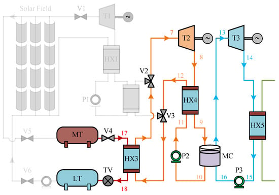
The system can operate in four distinct modes based on direct normal irradiance (DNI):
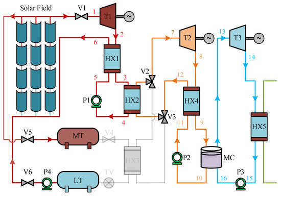
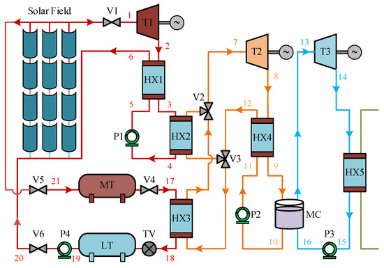
Normal Operation (Mode 1): Mode 1 is activated when DNI exceeds 450 W/m2, as illustrated in Figure 2. Under this condition, solar collection and cascade power conversion operate simultaneously. All fluid machinery required by the CORC is active, while the flow rates associated with P1 and P4 are regulated to maintain the required operating conditions. The solar energy not immediately consumed by the power cycle is transferred to the medium-temperature tank (MT) for storage.
Figure 2.
Mode 1—normal operation mode of the solar power CORC system.
(1) Saturated BDO vapour first enters the high-pressure expander T1, where part of its thermal energy is converted into power. The turbine exhaust is subsequently pre-cooled in HX1 and then transfers its remaining useful heat through HX2.
(2) In HX2, the bottom organic fluid is heated by the exhaust BDO vapour from the high-pressure turbine. The saturated vapour from the bottom organic working fluid in HX2 then flows into the Bottom ORC 1 expander (T2) for power generation.
(3) Similarly, the superheated vapour exiting T2 is cooled by HX4 before entering the mixing chamber (MC), where it exchanges heat with the second-stage working fluid at the bottom. The saturated vapour subsequently enters the Bottom ORC 2 expander (T3) and expands to generate additional power.
(4) Upon completion of this mode, most of the BDO mixture accumulates in the medium-temperature tank (MT).
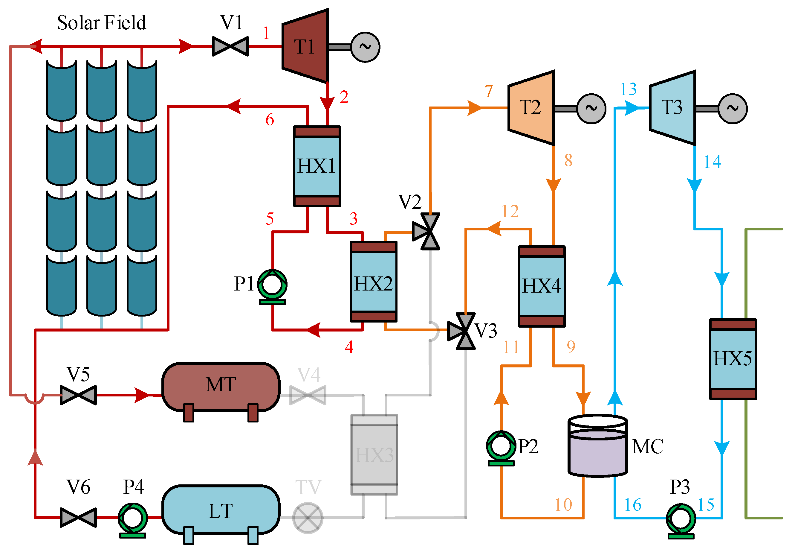
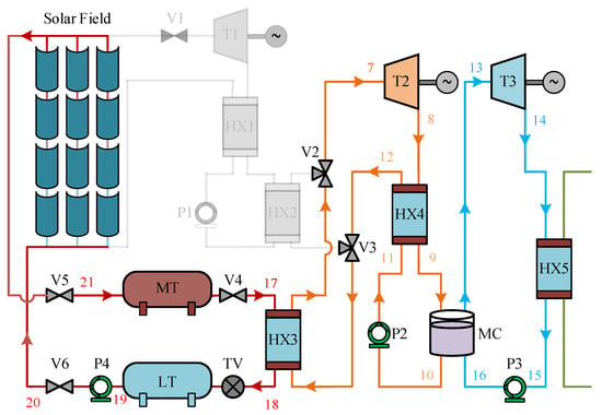
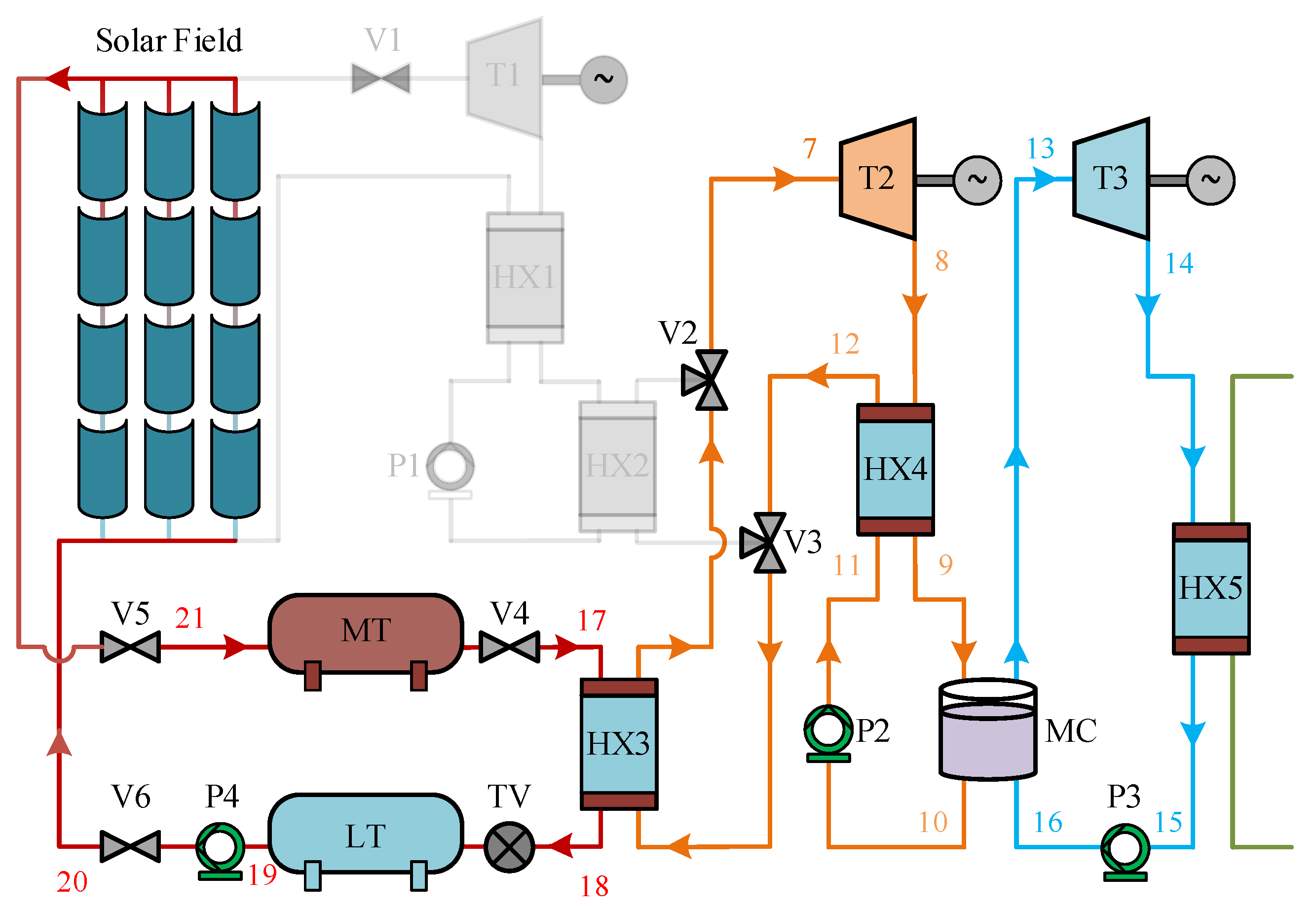
Combined Heat Collection and ORC Bottoming Cycle Power Production Mode (Mode 2): As shown in Figure 3, this mode is implemented during periods of insufficient solar availability, with the direct normal irradiance below 450 W/m2, such as in the early morning and late afternoon. In this operating scenario, the TV is switched to the open position, and pumps P2, P3, and P4 are used for energy conversion processes. During Mode 2, the MT releases heat to facilitate the operation of the bottom ORC system, while the top ORC system remains inactive. This allows efficient energy conversion from the available solar heat, thus optimizing the system’s performance despite lower irradiation levels.
Figure 3.
Mode 2—combined heat collection and ORC bottoming cycle power production mode of the solar power CORC system.
Transition Mode (Mode 3): The schematic diagram of this mode of operation is shown in Figure 4. At dusk, as solar irradiance decreases, all three subsystems commence operation, transitioning from normal operating Mode 1 to exothermic Mode 4. All valves and fluid equipment are activated. When solar irradiance reaches zero, Mode 3 concludes, and the system enters Mode 4.
Figure 4.
Mode 3—simultaneous heat collection and CORC power conversion mode of the solar power CORC system.
Bottom ORC Power Conversion (Mode 4): The heat discharge mode is illustrated in Figure 5. When solar irradiance decreases to zero and night sets in, Mode 4 becomes operational. The BDO working fluid in the MT flows into the LT and exchanges heat with the bottom ORC through HX3, facilitating the operation of the bottom ORC. The throttle valve (TV) opens, and pumps P2 and P3 are activated. In this mode, thermal–electrical conversion remains stable.
Figure 5.
Mode 4—heat discharge mode of the solar power CORC system.
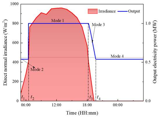
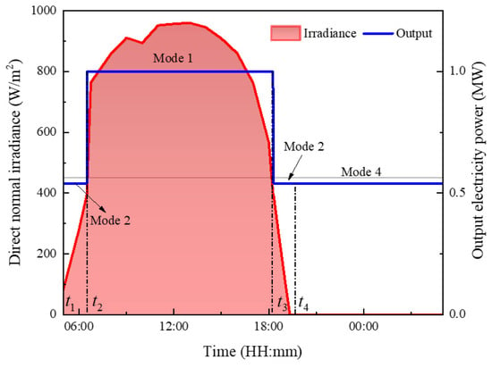
Figure 6 shows the variation in solar irradiance during typical sunny days in a certain region, as well as the operating time of each mode and the output power of the system at different periods. The working cycle of Mode 1 is from t2 to t3, the working cycle of Mode 2 is from t1 to t2, the working cycle of Mode 3 is from t3 to t4, and the working cycle of Mode 4 is from t4 to t1.
Figure 6.
Temporal variations in direct normal irradiance and operating modes during a typical day.
The thermal–electrical conversion system designed in this paper is flexible and can adapt to changes in solar radiation fluctuations during a normal day. This paper uses the BDO mixture directly for solar collectors and high-temperature ORC systems, which can operate at higher temperatures and pressures and reduce the heat transfer loss of traditional ORC systems through heat sources.
Due to the brief duration of dusk time, the operating period for Mode 3 is quite limited, resulting in thermal–electrical conversion during this mode accounting for a small proportion of the overall daily operation. To facilitate a comprehensive thermal performance analysis of the system, we simplified the typical daily irradiation intensity and operational modes as illustrated in Figure 7.
Figure 7.
Variations in direct normal irradiance and simplification of the operation modes.
3. Mathematical Model
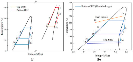
The thermodynamic model is established primarily for the representative operating conditions of Modes 1 and 4, whose processes are illustrated in Figure 8. Modes 2 and 3 are regarded as transitional off-design operating states. The numbered states in Figure 8 correspond to the thermodynamic state points identified in Figure 2 and Figure 5. Pressure losses and heat leakage in pipelines and heat exchangers are neglected, together with variations in kinetic and potential energy. The governing equations are implemented and solved in MATLAB (R2024a).
Figure 8.
T-s diagram of the solar power CORC system: (a) Mode 1; (b) Mode 4.
3.1. Turbines
The turbine work outputs of the top and bottom ORC cycles are evaluated using the following expression:
where εT represents the turbine isentropic efficiency for both the upper and lower ORC units; and indicate the corresponding working-fluid mass flow rates in the top and bottom ORC subsystems (kg/s), respectively; while h denotes the specific enthalpy associated with each thermodynamic state (kJ/kg).
3.2. Heat Exchangers
The heat balances in HX1, HX2, HX3, HX4 are determined by
HX1:
HX2:
HX3:
HX4:
3.3. Pump
The work required by the pumps P1, P2, P3, and P4 is determined by
where εp is the isentropic efficiency of the working-fluid pump.
3.4. Superheated Vapour of BDO
The required BDO saturation-state properties, including pressure, enthalpy, and density, are obtained from the corresponding supplier data [32]. Following the equivalent-hot-side-temperature (TEHST) ORC efficiency model originally developed by Li et al. [33], the thermal efficiency of the basic top ORC is expressed as:
In this formulation, v indicates the specific volume corresponding to each state point (m3/kg), εg is the electrical generator efficiency, and TEHST represents the equivalent hot-source temperature (K), obtained according to the following equation:
Meanwhile, the efficiency of the top ORC with the most basic structure can be expressed as:
Based on Equations (12) and (14), h2 is subsequently obtained.
For most organic fluids used in ORC systems, the liquid phase can be considered incompressible, with heat removal mainly taking place through the condensation process [34]. Therefore, h5s is calculated as follows:
Direct entropy data for the BDO mixture are unavailable in the adopted property source. A reference entropy is therefore introduced because only entropy differences affect the present thermodynamic calculations. The saturated-liquid state at 373.15 K (100 °C) is assigned an entropy of 3 kJ/(kg·K), and the entropy at other states is evaluated relative to this reference using the following thermodynamic relation:
Applying Equation (16) between states 2 and 2s under the condition dp = 0 gives the entropy at state 2 as:
where is the average temperature at points 2 and 2s, and the enthalpy of point 2s is calculated by:
3.5. Thermal Efficiency
The evaporator heat absorption of the working fluids in both ORC stages is obtained according to the following expression:
The corresponding work production of the top-cycle ORC, bottom-cycle ORC, and integrated CORC arrangement in Mode 1 is evaluated using the following expression:
The efficiency assessment of the top-cycle ORC, bottom-cycle ORC, and combined CORC arrangement in Mode 1 is performed according to the following equations:
The work, heat, and thermal efficiency of the bottom ORC in Mode 2 and Mode 4 are expressed as:
3.6. Entropy Generation
The entropy generation of the top turbine T1, bottom turbine T2, and T3 is expressed as:
The entropy generation of the heat exchangers HX1, HX2, HX3, HX4, HX5, and MC is calculated by:
The entropy generation of the pump P1, P2, P3 and P4 is determined by:
3.7. Economic Assessment
Based on the system’s 24 h continuous energy supply capability, core calculation formulas for the annual total electricity generation and heat supply of this cogeneration system were derived, providing a quantitative basis for subsequent economic evaluations:
Based on the annual electricity generation and annual heat-supply formulas, the annual revenue can be calculated. The revenue calculation uses the following formula:
In the formula, Ce is the time-of-use electricity tariff (USD/kWh), and Ch is the heating tariff (USD/kWh). All monetary values originally expressed in CNY were converted into USD using an exchange rate of 1 USD = 6.936 CNY.
4. Results and Discussion
In the selected reference condition, the solar field outlet BDO is characterized by a liquid–vapour mixture at 400 °C. The detailed simulation settings and adopted parameters are presented in Table 1.
Table 1.
Specific parameters in the simulation.
4.1. Thermodynamic Performance of Mode 1
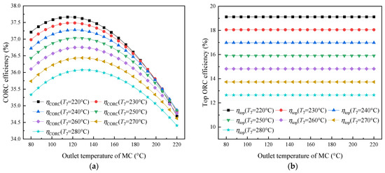
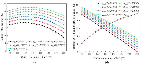
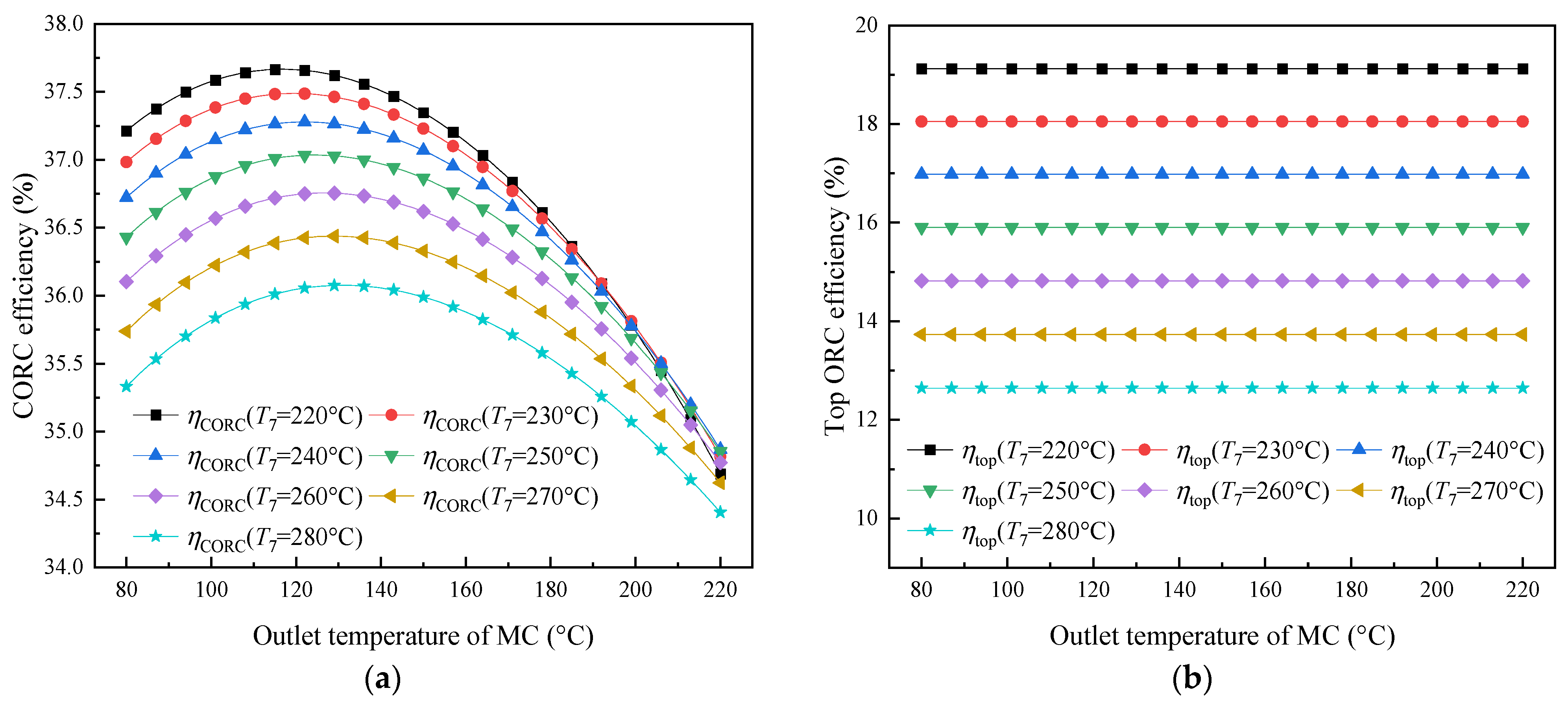
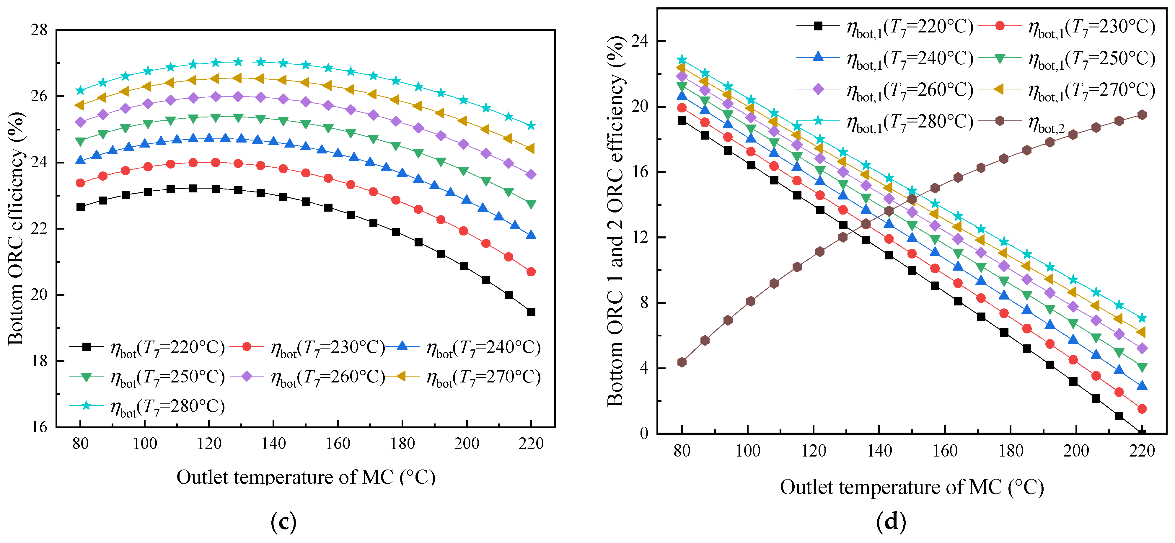
In Mode 1, when solar irradiance exceeds 450 W/m2, the CORC system operates normally and generates a significant amount of electricity. The variations in thermal efficiency of the CORC system in Mode 1 are illustrated in Figure 9. At this point, thermal–electrical conversion efficiency reaches its peak. However, as the inlet temperature (T7) of the bottom first-stage ORC system expander rises, thermal efficiency decreases. Additionally, as the temperature (T10) of the MC increases, the thermal efficiency initially rises before ultimately declining.
Figure 9.
Variation in the thermal efficiency of the CORC system: (a) CORC; (b) top ORC; (c) bottom ORC; (d) Bottom ORC 1 and 2.
For each value of T7, the CORC efficiency reaches an optimum as T10 varies. Increasing T7 from 220 to 280 °C shifts the optimum T10 from 117 to 131 °C, while the corresponding maximum CORC efficiency decreases from 37.67% to 36.08%. At T7 = 230, 240, 250, 260, and 270 °C, the optimized efficiencies are 37.49%, 37.28%, 37.03%, 36.76%, and 36.44%, respectively, with corresponding T10 values of 119, 122, 124, 127, and 129 °C. The highest CORC efficiency of 37.67% is therefore obtained at T7 = 220 °C and T10 = 117 °C.
Figure 9b,c further separate the responses of the top and bottom cycles. At T7 = 220 °C, the top ORC reaches a thermal efficiency of 19.12%, whereas the optimized bottom-ORC efficiency is 23.22%. With T7 increasing from 220 to 280 °C, the maximum bottom-cycle efficiency rises from 23.22% to 27.04%; the corresponding values at 230, 240, 250, 260, and 270 °C are 24.00%, 24.72%, 25.39%, 25.99%, and 26.55%, respectively. The different responses of the top and bottom cycles to T7 mainly result from the redistribution of thermal energy within the cascade system. When T7 increases, the heat-addition temperature of Bottom ORC 1 increases, thereby increasing its potential for heat-to-work conversion. However, the thermodynamic state at the outlet of HX2 also changes, which modifies the amount of residual thermal energy transferred from the top ORC to the bottom cycle. Therefore, although the efficiency of the bottom ORC increases with T7, the overall CORC efficiency gradually decreases because the energy distribution and temperature matching between the top and bottom cycles are simultaneously altered. The mixing-heater temperature T10 further determines the energy distribution between Bottom ORC 1 and Bottom ORC 2. Increasing T10 reduces the effective expansion range of Bottom ORC 1 but increases the temperature level available to Bottom ORC 2. Consequently, the efficiencies of the two bottom stages vary in opposite directions, resulting in an optimum T10 at which the overall CORC efficiency reaches its maximum.
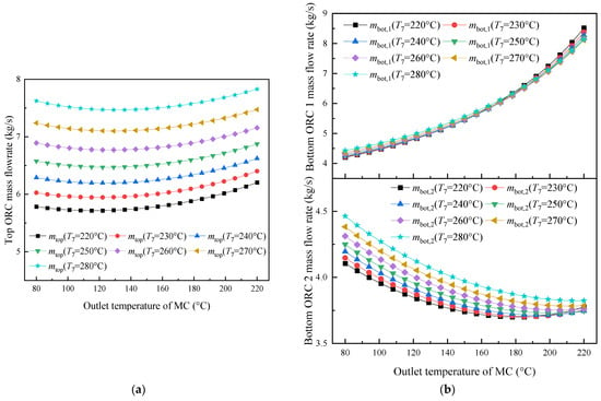
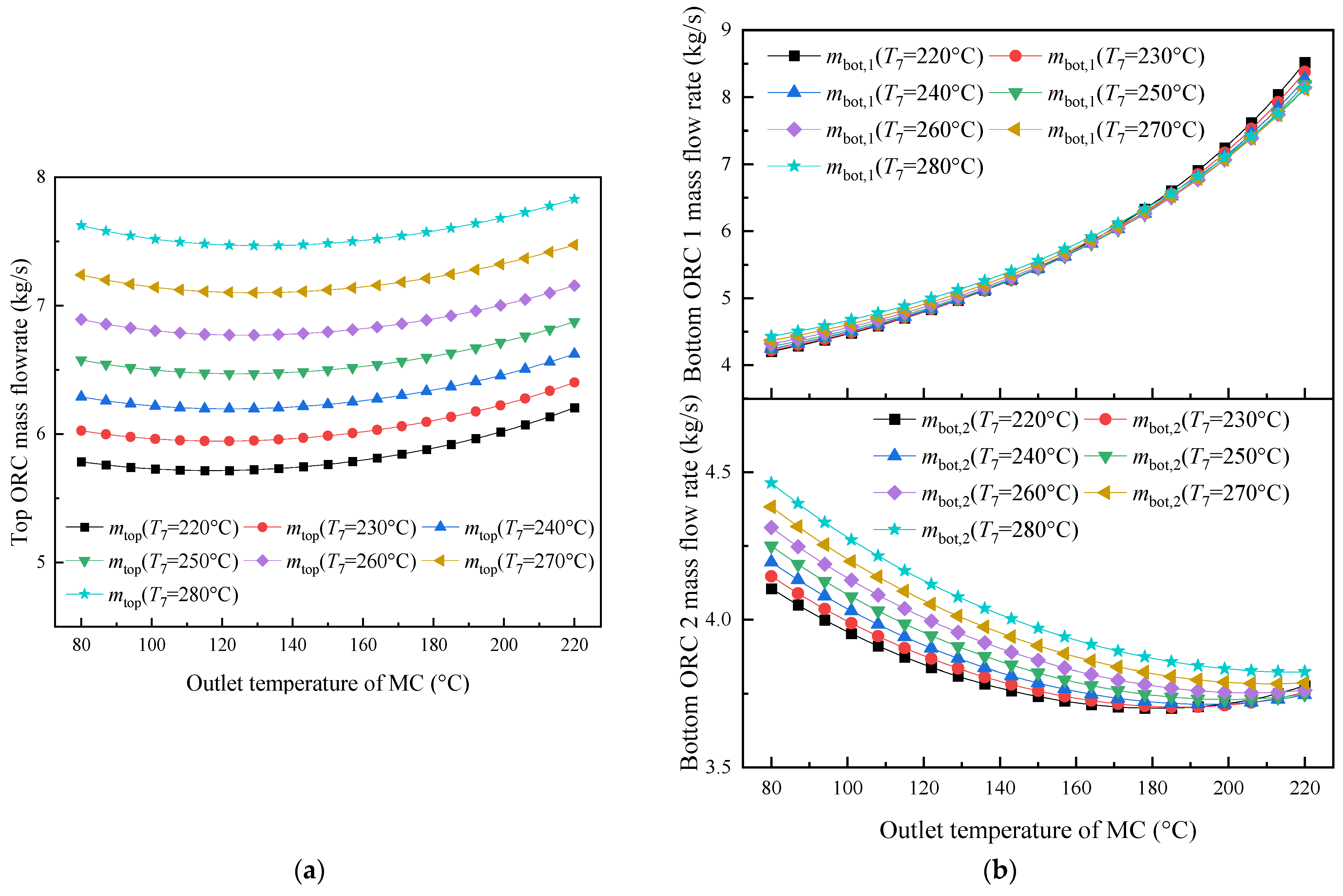
Figure 10 illustrates the mass flow rates of the top and bottom ORCs. As shown in Figure 10a, with the temperature of the MC increasing, the mass flow rate of the top ORC exhibits a relatively smooth trend, initially decreasing before increasing again. The observed variation results from maintaining the CORC output at a fixed value of 1 MW, causing the ORC mass flow rate to be closely linked with the efficiency performance. As the inlet and outlet conditions of HX2 are maintained constant, the required mass flow rate of the top ORC working fluid is primarily determined by the heat transfer performance of HX2.
Figure 10.
Variation in the mass flow rate: (a) top ORC; (b) Bottom ORC 1 and 2.
In contrast (see Figure 10b), the mass flow rates through the bottom turbines (T2 and T3) show differing trends. The mass flow rate for turbine 1 gradually increases, while that for turbine 2 decreases. The rise in MC temperature reduces the enthalpy drop across states 7–12, which increases the required working-fluid circulation in HX3. Meanwhile, the enthalpy difference associated with states 13–16 is enhanced. Because the total rated output is maintained at 1 MW, changes in the specific work and heat-transfer requirements of the individual stages must be compensated by corresponding changes in the working-fluid mass flow rates. The opposite variations in the Bottom ORC 1 and Bottom ORC 2 mass flow rates therefore reflect the redistribution of the required heat input and power production between the two cascade stages.
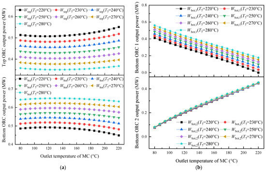
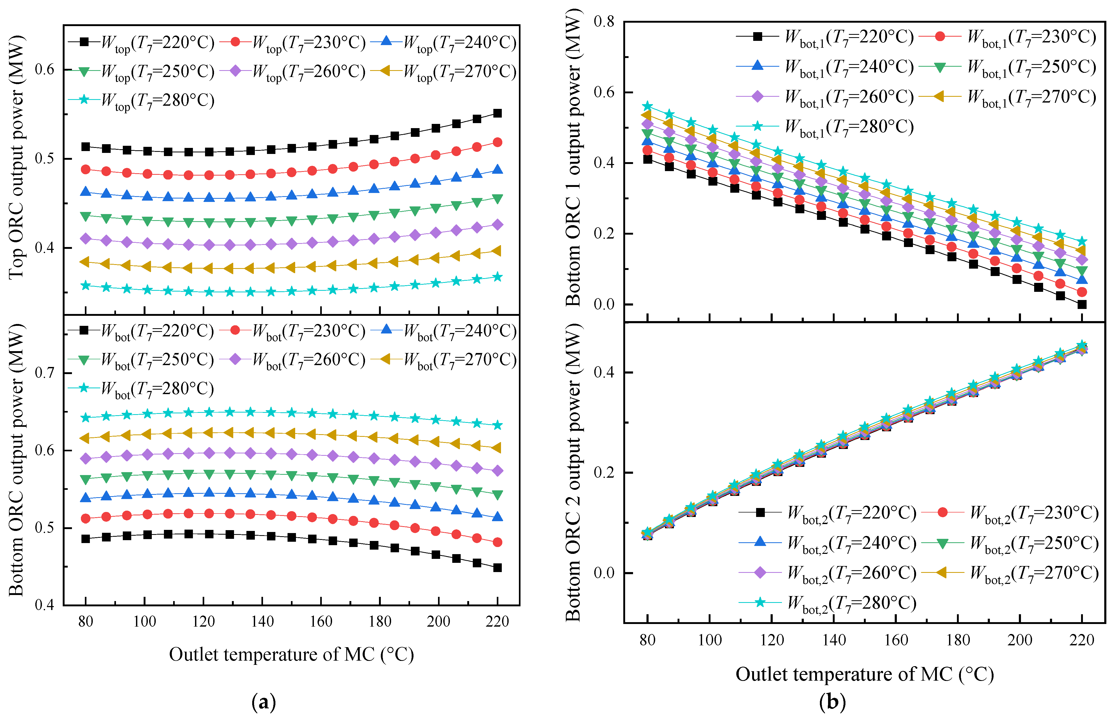
Figure 11a displays minor fluctuations in output power as the temperature of the mixing chamber (MC, T10) increases. The overall output power aligns with the design output of 1 MW. As the MC temperature T10 rises, the power output of the top ORC initially decreases before rising again. In contrast, the outputs of the bottom ORCs (1 and 2) show gradual increases and decreases, respectively. At specific temperatures for T7 (220 °C, 230 °C, 240 °C, 250 °C, 260 °C, 270 °C, and 280 °C), the minimum output powers of the top ORC system are recorded as 0.51 MW, 0.48 MW, 0.46 MW, 0.43 MW, 0.40 MW, 0.38 MW, and 0.35 MW. Meanwhile, the maximum output powers of the bottom ORC system are 0.49 MW, 0.52 MW, 0.54 MW, 0.57 MW, 0.60 MW, 0.62 MW, and 0.65 MW. Figure 11b illustrates the output power of the Bottom 1 and Bottom 2 ORC systems. The first bottom ORC stage experiences a gradual decrease in power output with increasing MC temperature, whereas the output power of Bottom 2 gradually increases.
Figure 11.
Variation in the power output: (a) top and bottom ORCs; (b) Bottom ORC 1 and 2.
The optimal solution of the CORC system is characterized in Table 2, where the selected operating variables and performance outputs are given for different T7 conditions. The temperature, enthalpy, pressure, and mass flow rate distributions at individual state points corresponding to the best-performing high-temperature CORC case are further documented in Table 3.
Table 2.
Parameters of the high-temperature CORC system at maximum CORC efficiency.
Table 3.
Parameter distribution at optimum CORC efficiency.
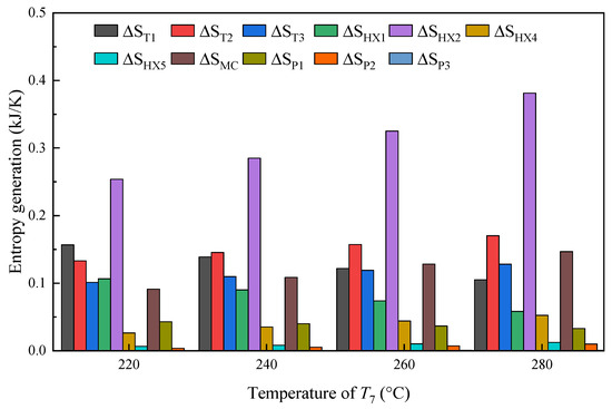
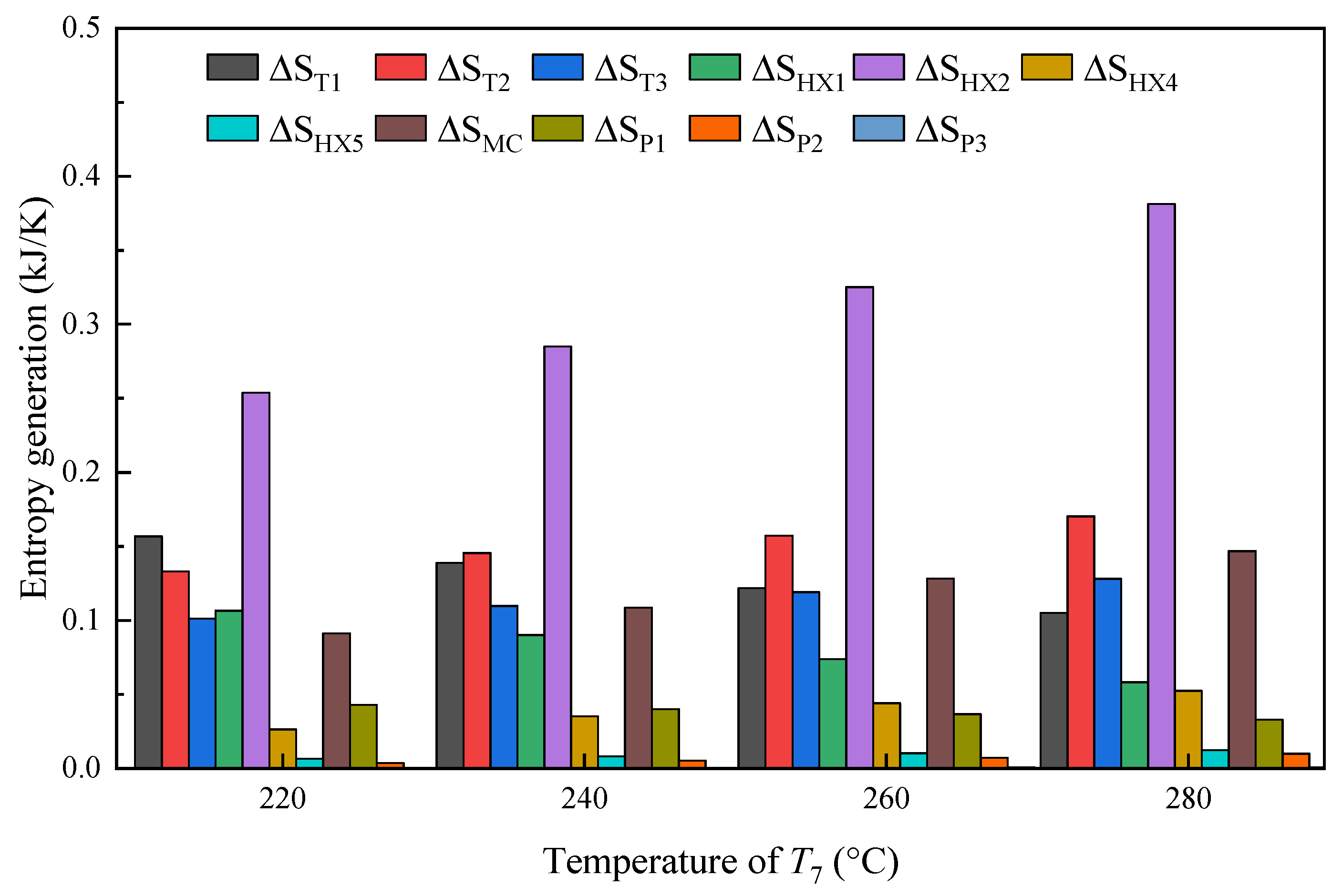
Figure 12 provides a breakdown of entropy generation contributions from the different components of the high-temperature CORC system when operating at its highest efficiency point. Entropy production can be used to characterize the irreversible behaviour and corresponding exergy degradation occurring in the CORC system. At various T7 temperatures, HX2 is identified as the main contributor to entropy production, accounting for nearly one-third of the total entropy generation within the system. For T7 values of 220 °C, 240 °C, 260 °C, and 280 °C, the entropy generation of HX2 is measured at 0.25 kJ/K, 0.29 kJ/K, 0.33 kJ/K, and 0.38 kJ/K, respectively. This significant entropy generation can be attributed to the large average temperature difference during heat transfer in HX2, with the inlet temperature of the BDO mixture side reaching 266.9 °C, while the inlet temperature of the bottom ORC fluid side using toluene is 142.8 °C. In contrast, the entropy generation of heat exchanger HX5 and pumps P2 and P3 remains relatively low.
Figure 12.
Entropy generation distribution of the CORC system under optimal efficiency conditions.
4.1.1. Influence of Condensation Temperature
An investigation of condensation-temperature effects on the high-temperature CORC system performance is carried out. In the evaluated configuration, toluene serves as the working medium for the bottom ORC, while the temperatures associated with states T1 and T4 are set to 400 °C and 230 °C, respectively. The pressure at point 4 with a temperature of 228 °C exceeds 50 kPa, which prevents high vacuum in heat exchanger HX2, thereby reducing the technical requirements and cost of the heat exchanger.
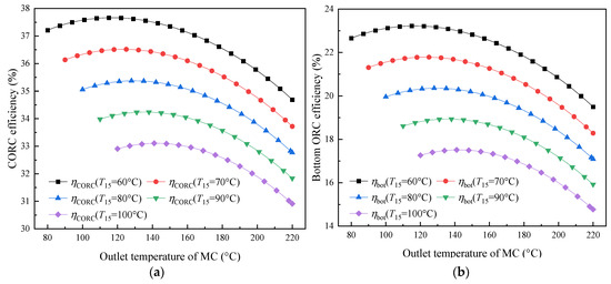
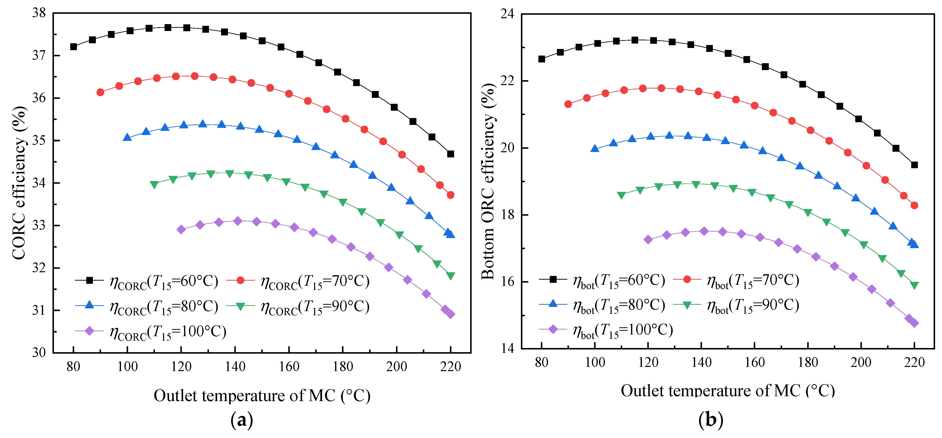
The relationship between condensation conditions and CORC system efficiency is examined in Figure 13a, where the variation in thermal performance can be observed. This parameter plays a significant role in cogeneration operation because it influences the achievable heat delivery temperature. Lower condensation temperatures contribute to enhanced CORC system efficiency, resulting in a continuous rise in overall thermal performance. Since T1 and T4 are fixed, the top ORC efficiency also remains at the value of 19.12%. When T15 is set to 60 °C, 70 °C, 80 °C, 90 °C, and 100 °C, with the mixing chamber temperature T10 at 117 °C, 123 °C, 129 °C, 136 °C and 142 °C, the maximum thermal efficiencies of the CORC system in Mode 1 are recorded as 37.67%, 36.52%, 35.38%, 34.24%, and 33.11%, respectively. This efficiency is primarily determined by the evaporation temperature (T7) and the mixing chamber temperature (T10). Figure 13b presents the thermal efficiency of the bottom ORC system during Mode 1 operation. As the condensation temperature decreases, the efficiency of the bottom ORC shows an upward trend. For T15 values of 60 °C, 70 °C, 80 °C, 90 °C, and 100 °C, the maximum thermal efficiencies of the bottom ORC system are recorded as 23.22%, 21.79%, 20.36%, 18.93%, and 17.51%, respectively. The decrease in thermal efficiency with increasing condensation temperature is mainly attributed to the increase in the heat-rejection temperature and the corresponding reduction in the available expansion enthalpy drop of the bottom-cycle working fluid. A higher condensation temperature therefore decreases the amount of work that can be extracted during expansion. However, it simultaneously increases the temperature level of the recoverable heat, which is favourable for useful heat supply. Consequently, the condensation temperature represents a direct trade-off between power-generation efficiency and the quality of the thermal output in the cogeneration system. This power–heat trade-off is also consistent with the solar ORC combined heat and power system reported in [35], in which condenser heat was recovered for useful hot-water production while the electrical performance was simultaneously affected by the heat-rejection conditions.
Figure 13.
Effect of condensation temperature on the thermal efficiency: (a) CORC; (b) bottom ORC.
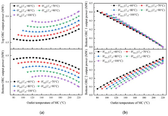
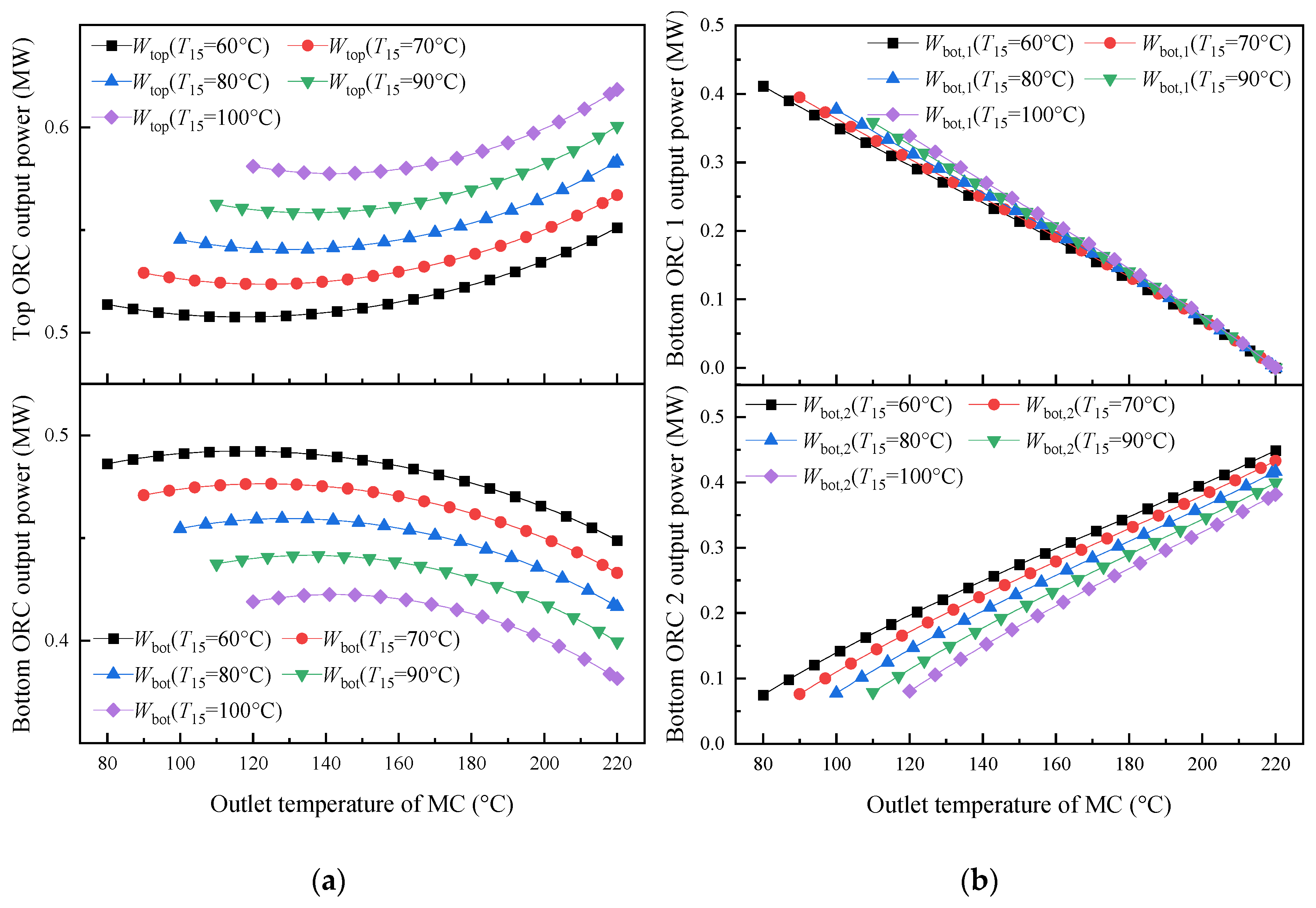
Figure 14 illustrates the output power of various ORC systems at different condensation temperatures. As shown in Figure 14a, the output power of the top ORC system increases with rising condensation temperature (T15), while the output power of the bottom ORC system decreases. Figure 14b specifically depicts the output power of the bottom two-stage ORC system. As the mixing chamber temperature increases, the output power of the bottom first-stage ORC system declines, whereas the output power of the second-stage ORC system increases.
Figure 14.
Variation in the power output: (a) top and bottom ORCs; (b) Bottom ORC 1 and 2.
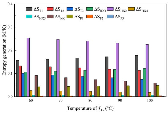
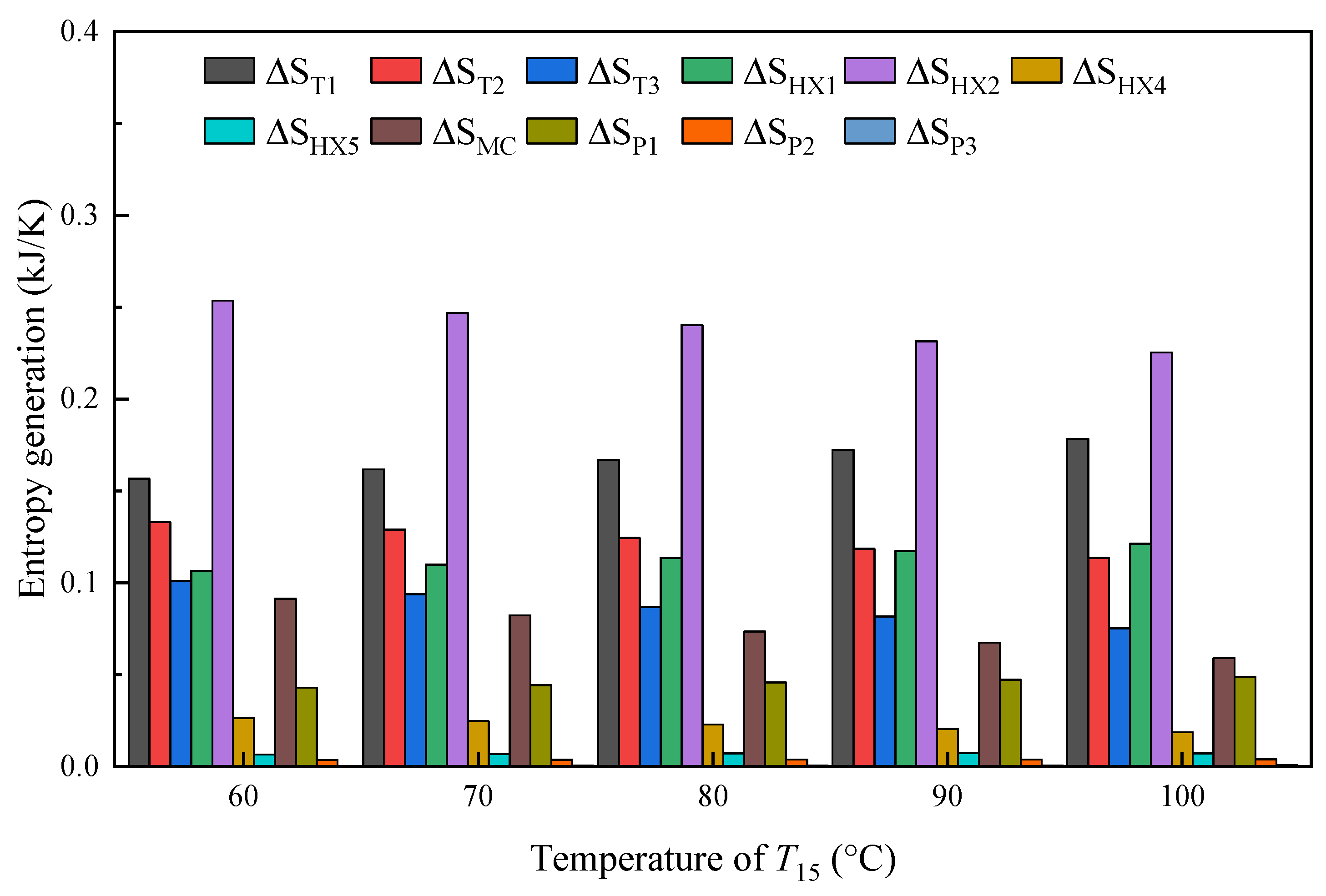
The component-level irreversibility characteristics of the bottom ORC in Mode 1 are analyzed in Figure 15. It is found that HX2 dominates the entropy production of the system, mainly because of the unavoidable thermal mismatch during heat exchange between the external heat source and the ORC working fluid. For T15 values of 60 °C, 70 °C, 80 °C, 90 °C, and 100 °C, these losses account for 27.50%, 27.31%, 27.12%, 26.65%, and 26.45% of the total exergy loss, respectively.
Figure 15.
Irreversibility characteristics of the CORC system under the optimal operating condition.
4.1.2. Influence of Evaporation Temperature
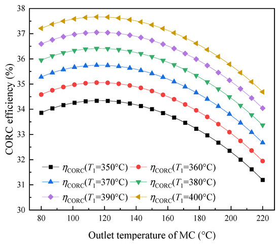
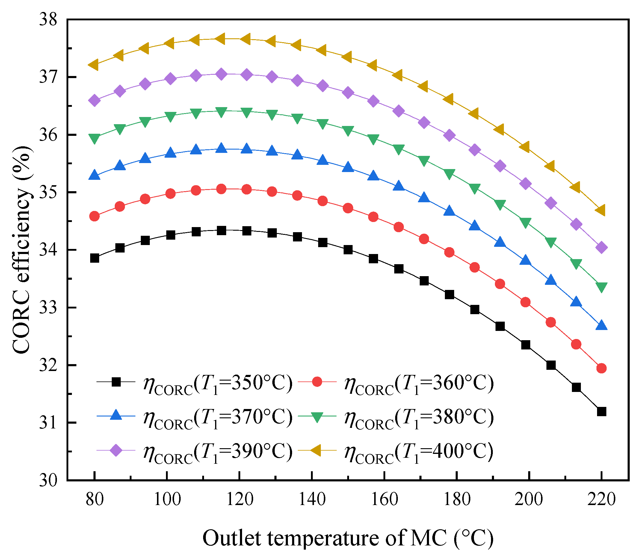
The performance response of the high-temperature CORC system under different evaporation temperature conditions is analyzed. For the thermodynamic analysis, T7 is set to 220 °C, and T15 is set to 60 °C. The efficiency behaviour of the CORC configuration is evaluated for various operating scenarios, with the corresponding results shown in Figure 16. Increasing the evaporation temperature contributes to higher efficiency, while the effect of MC temperature is characterized by an optimal point, beyond which further increases cause efficiency deterioration. Specifically, when T1 is at 350 °C, 360 °C, 370 °C, 380 °C, 390 °C, and 400 °C, with the MC temperature at 117 °C, the thermal efficiencies of the CORC system are 34.34%, 35.06%, 35.75%, 36.41%, 37.05%, and 37.67%, respectively.
Figure 16.
Effect of evaporation temperature on the thermal efficiency of the CORC system.
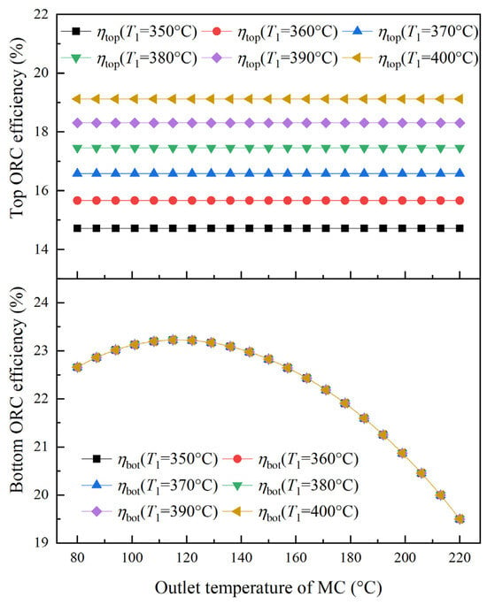
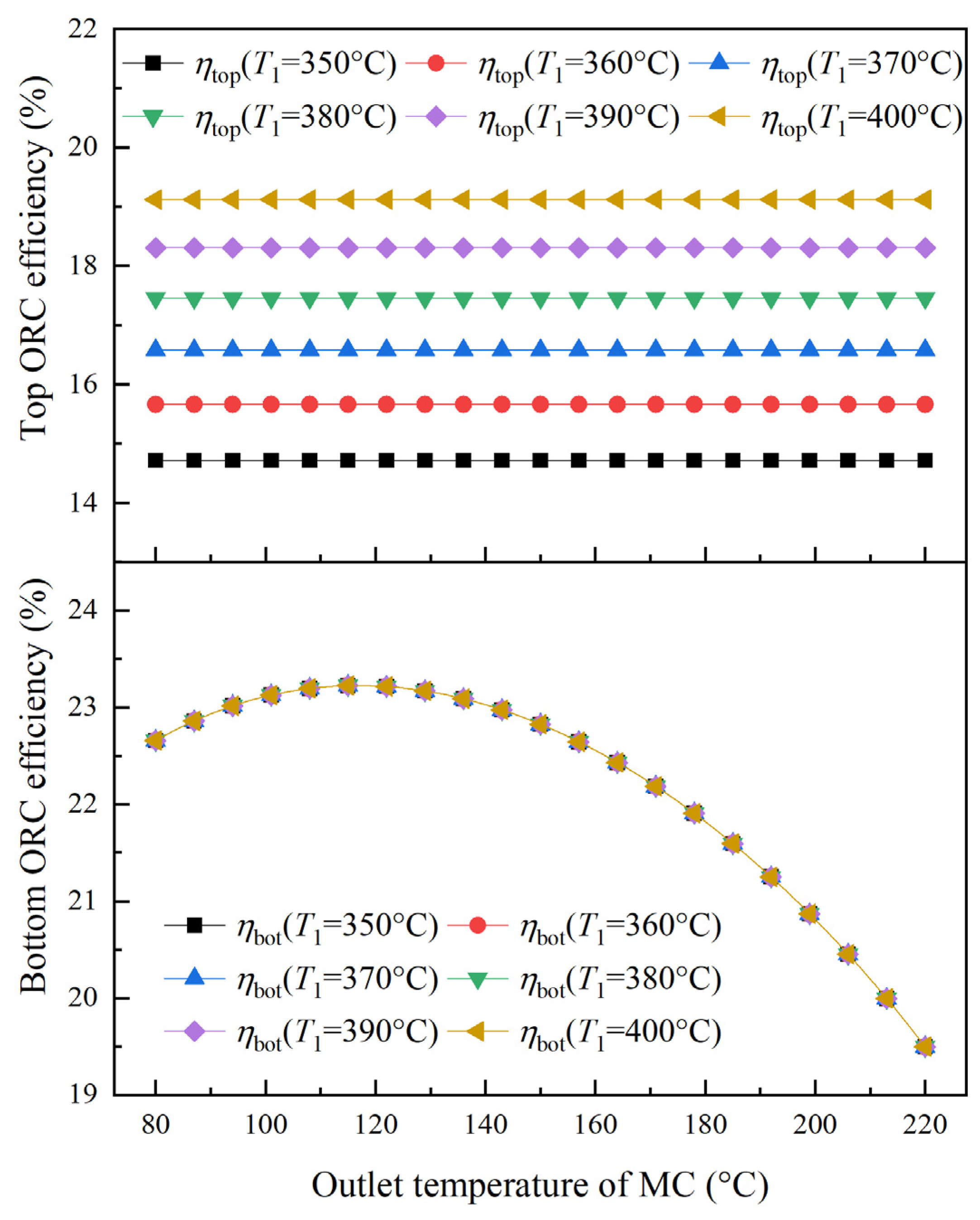
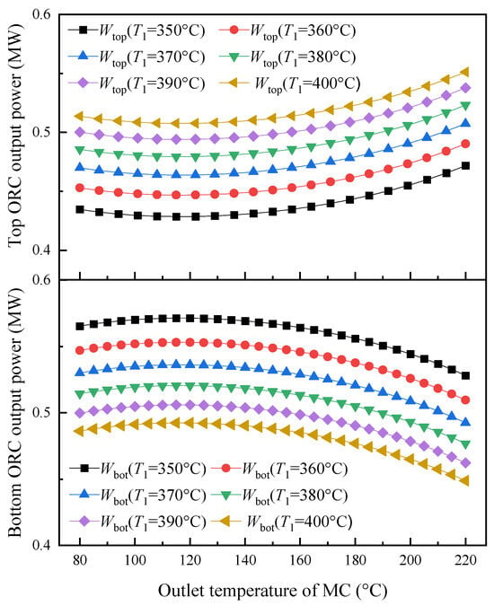
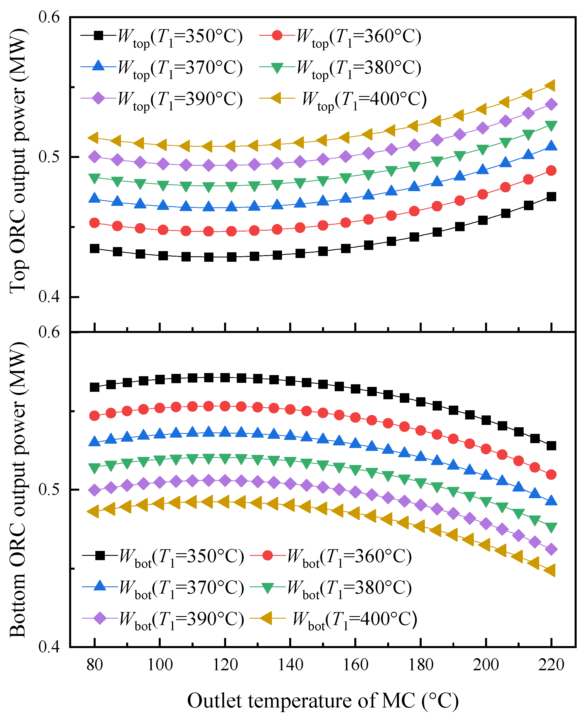
Figure 17 shows the dependence of ORC thermal efficiency on evaporation temperature for both the upper and lower cycles. The results indicate that elevating the evaporation temperature (T1) leads to a continuous improvement in the thermal efficiency of the top ORC. In contrast, the efficiency of the bottom ORC exhibits a trend of initially increasing and then decreasing with rising MC temperature, reaching a maximum of 23.22%. Figure 18 illustrates the variation in output power for both the top and bottom ORC systems as the evaporation temperature changes. The variation in evaporation temperature has opposite effects on the two ORC subsystems: higher temperatures promote greater power production in the top ORC, whereas the bottom ORC experiences a decrease in output. Increasing T1 raises the average temperature level of heat addition in the high-temperature ORC and increases the thermodynamic potential for converting the supplied heat into work. Consequently, both the thermal efficiency and power contribution of the top ORC increase. The increase in T1 enhances energy utilization within the top ORC stage, which limits the remaining thermal input transferred to the bottom cycle. Consequently, the power output of the bottom cycle decreases with increasing T1. This trend is consistent with the equivalent-hot-side-temperature model reported in our previous study [31], which showed that a higher effective heat-addition temperature generally corresponds to a higher ORC thermal efficiency under given operating conditions.
Figure 17.
Effect of evaporation temperature on the thermal efficiency of the bottom ORC.
Figure 18.
Variation in the CORC power output at different evaporation temperatures.
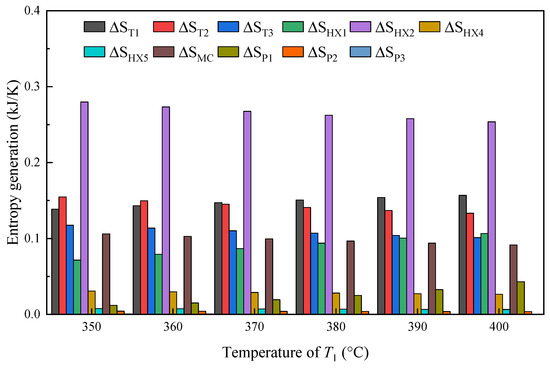
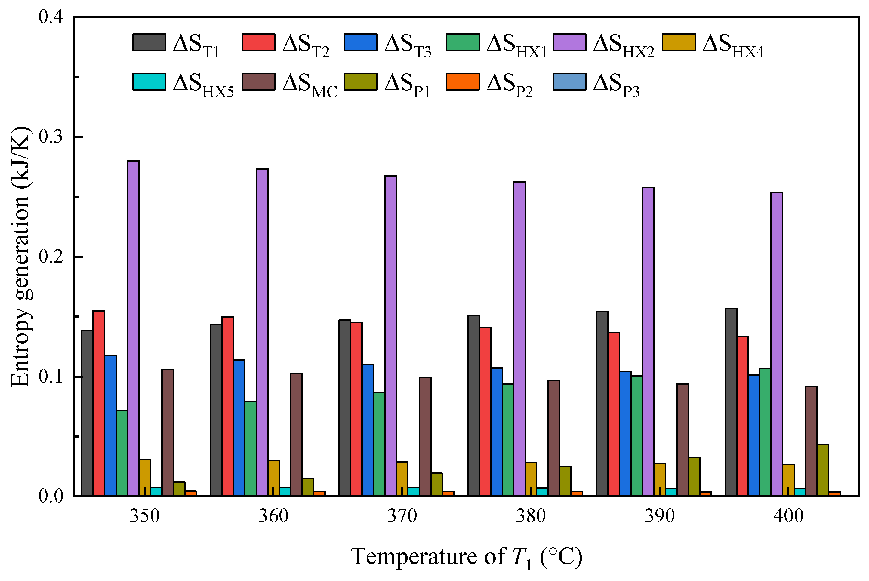
Figure 19 depicts the thermodynamic irreversibility under normal operating mode (Mode 1). The heat transfer damage from the hot-side fluid to the bottom ORC fluid in HX2 is the most significant. When T1 is set to 350 °C, 360 °C, 370 °C, 380 °C, 390 °C, and 400 °C, the entropy generation of HX2 is measured at 0.28 kJ/K, 0.27 kJ/K, 0.27 kJ/K, 0.26 kJ/K, 0.26 kJ/K and 0.25 kJ/K, and these temperatures account for 30.32%, 29.77%, 29.21%, 28.66%, 28.09%, and 27.49% of the total exergy loss, respectively. Additionally, the entropy generation of expanders T1, T2, and T3 is also high.
Figure 19.
Entropy generation at optimum bottom ORC efficiency in different evaporation temperatures.
4.1.3. Influence of Bottom ORC Working Fluid
This section focuses on commercially available organic working fluids with higher critical temperatures, such as toluene [36,37], cyclohexane [38,39], benzene [40,41], and D4 [42,43]. These fluids are utilized in the thermodynamic cycle of the bottom ORC to investigate their effects on the thermal performance of the system. Table 4 provides the key thermophysical property data for the four investigated working fluids: toluene, D4, benzene, and cyclohexane.
Table 4.
Thermophysical properties of the working fluids in the bottom ORC.
In this section, the system parameters are set with an evaporation temperature T1 of 400 °C, an inlet temperature of the bottom ORC expander at 230 °C, and a condensation temperature T15 of 60 °C. The thermal performance of the system using different working fluids in the bottom ORC is analyzed in this section.
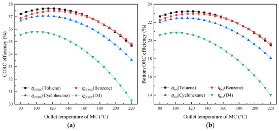
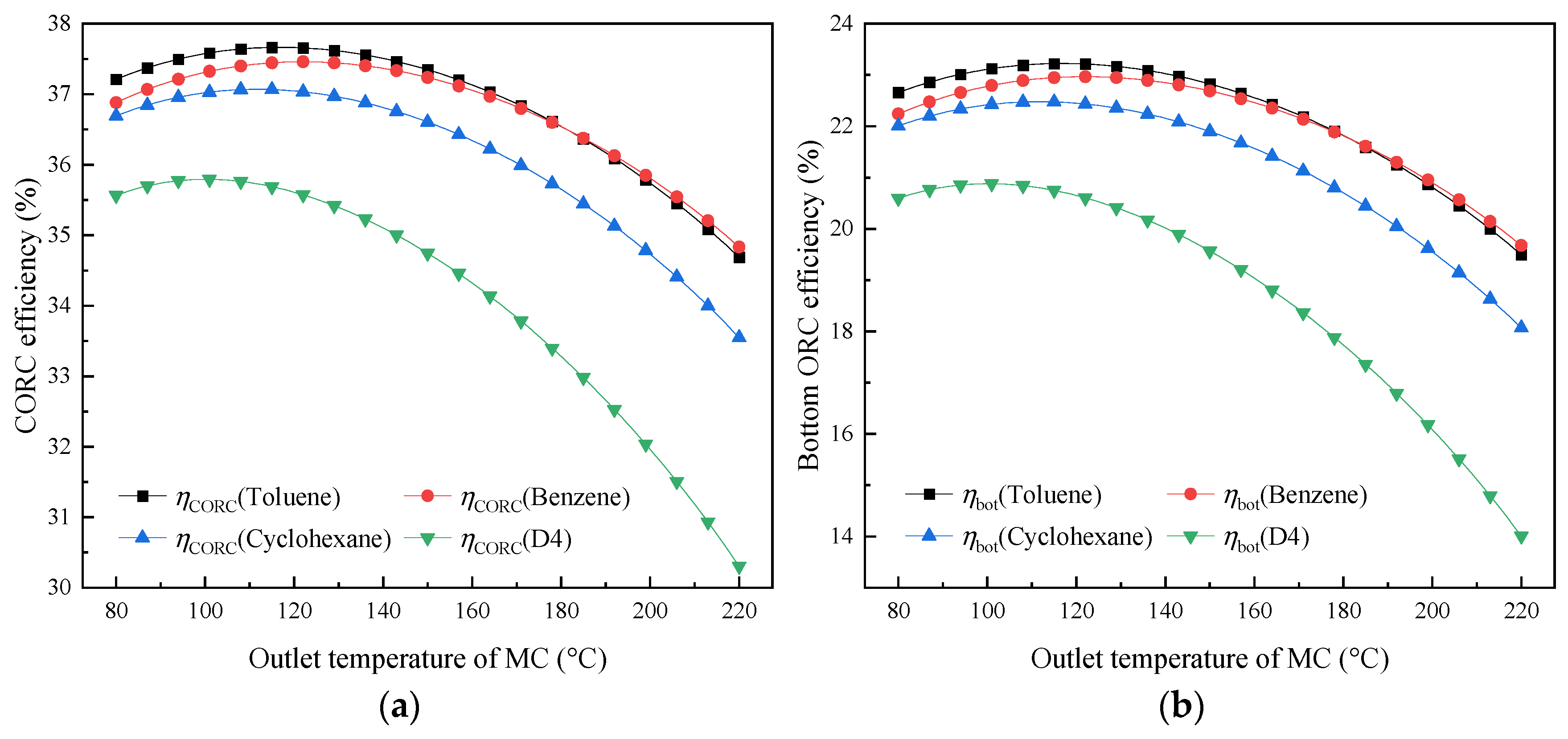
The results in Figure 20a indicate that toluene provides the best thermal efficiency among the investigated CORC systems, whereas D4 leads to the least favourable efficiency performance, which is mainly associated with the superior thermophysical properties of toluene, particularly its high critical temperature and large latent heat of vaporization. Both systems show a trend of initially increasing thermal efficiency, followed by a decrease as the MC temperature rises. The maximum thermal efficiencies for the four systems employing toluene, benzene, cyclohexane, and D4 at their respective MC temperatures of 117 °C, 122 °C, 112 °C, and 100 °C are 37.67%, 37.46%, 37.07%, and 35.79%.
Figure 20.
Variation in the thermal efficiency at different fluids: (a) CORC; (b) bottom ORC.
Figure 20b depicts the influence of MC temperature on the bottom ORC thermal performance. For each of the four working fluids considered, the efficiency shows a peak value as the MC temperature rises, increasing at first and then decreasing. The reason for this trend is that the thermal boundary conditions of the top ORC, including evaporation and condensation temperatures, are kept constant; that is, the thermal efficiency of the top ORC system is fixed. At this time, the overall efficiency trend of the system is related to the bottom ORC system.
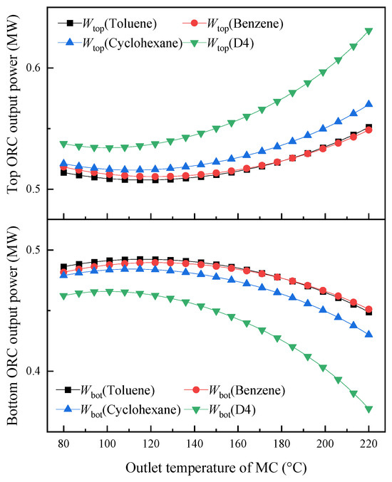
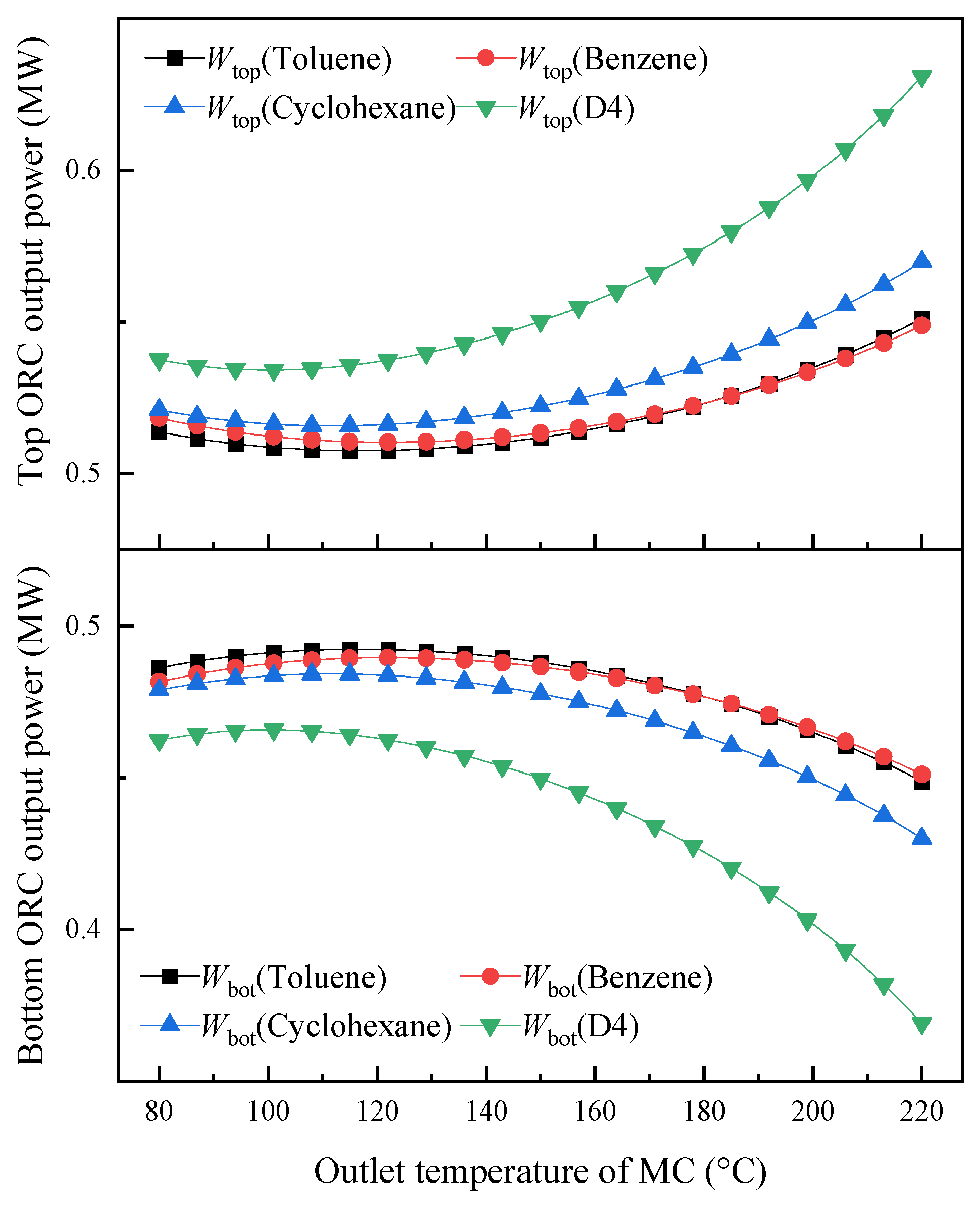
Figure 21 shows the relationship between the system output power and MC temperature corresponding to the four working fluids. The thermal efficiency of the top ORC system shows a trend of first decreasing and then increasing, while the thermal efficiency of the bottom ORC system shows a trend of first increasing and then decreasing, with a significant change in D4 output power.
Figure 21.
Variation in the top and bottom ORC thermal efficiency of the CORC system for different working fluids.
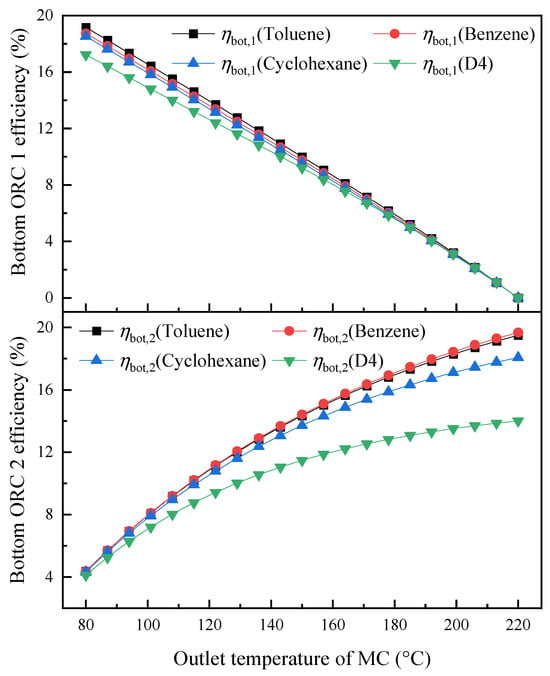
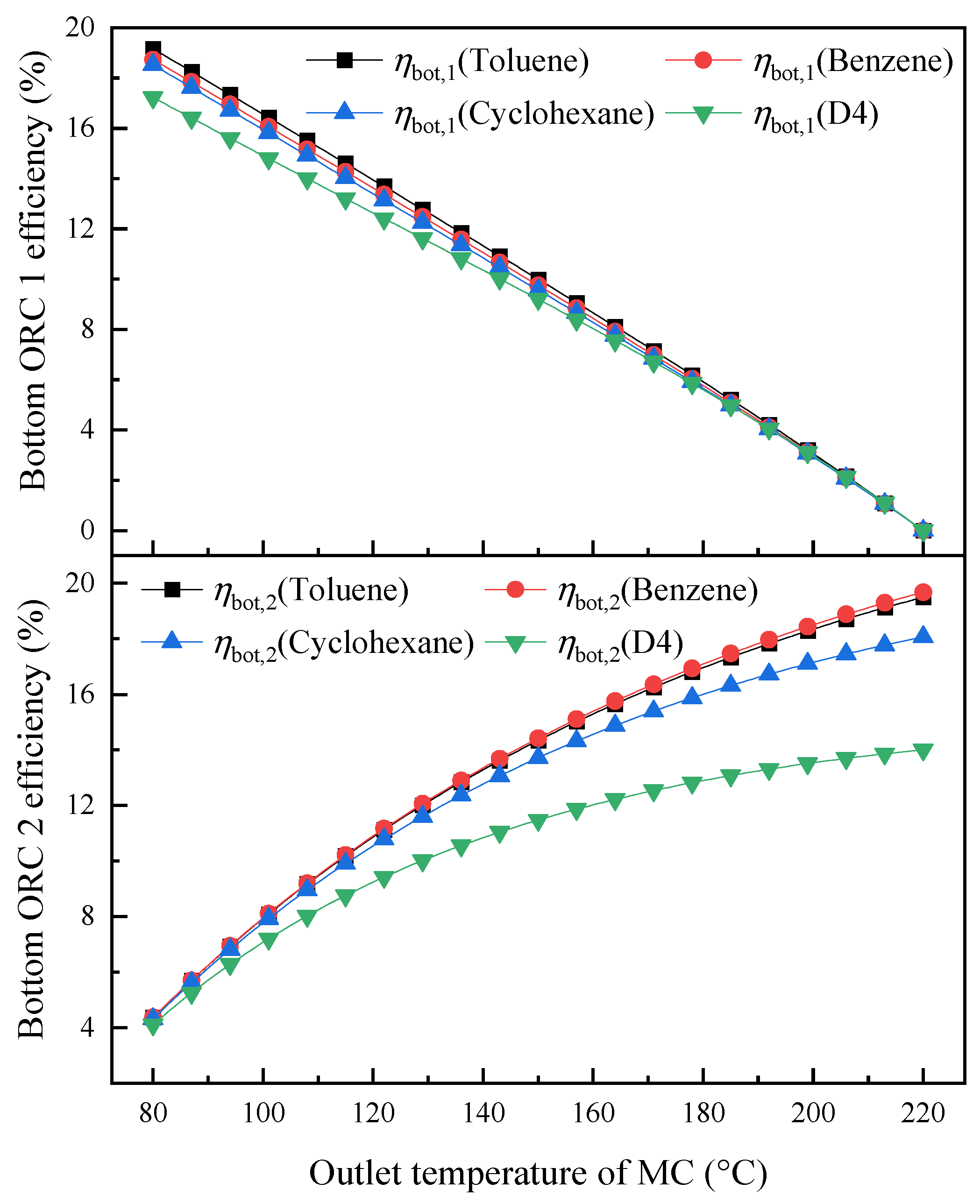
The influence of MC temperature on the efficiency evolution of the lower ORC subsystem is analyzed in Figure 22. A common decreasing trend is found for the first-stage bottom ORC, where higher MC temperatures result in lower thermal efficiency for each of the four working fluids considered. In contrast, the thermal efficiency of the bottom second-stage ORC increases. When using D4, the thermal efficiency of the bottom-stage ORC system is significantly reduced compared to the other three working fluids.
Figure 22.
Variation in the thermal efficiency of Bottom ORC 1 and 2 of the CORC system for different working fluids.
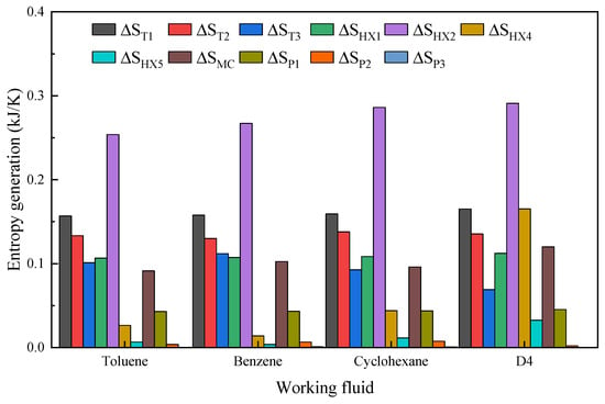
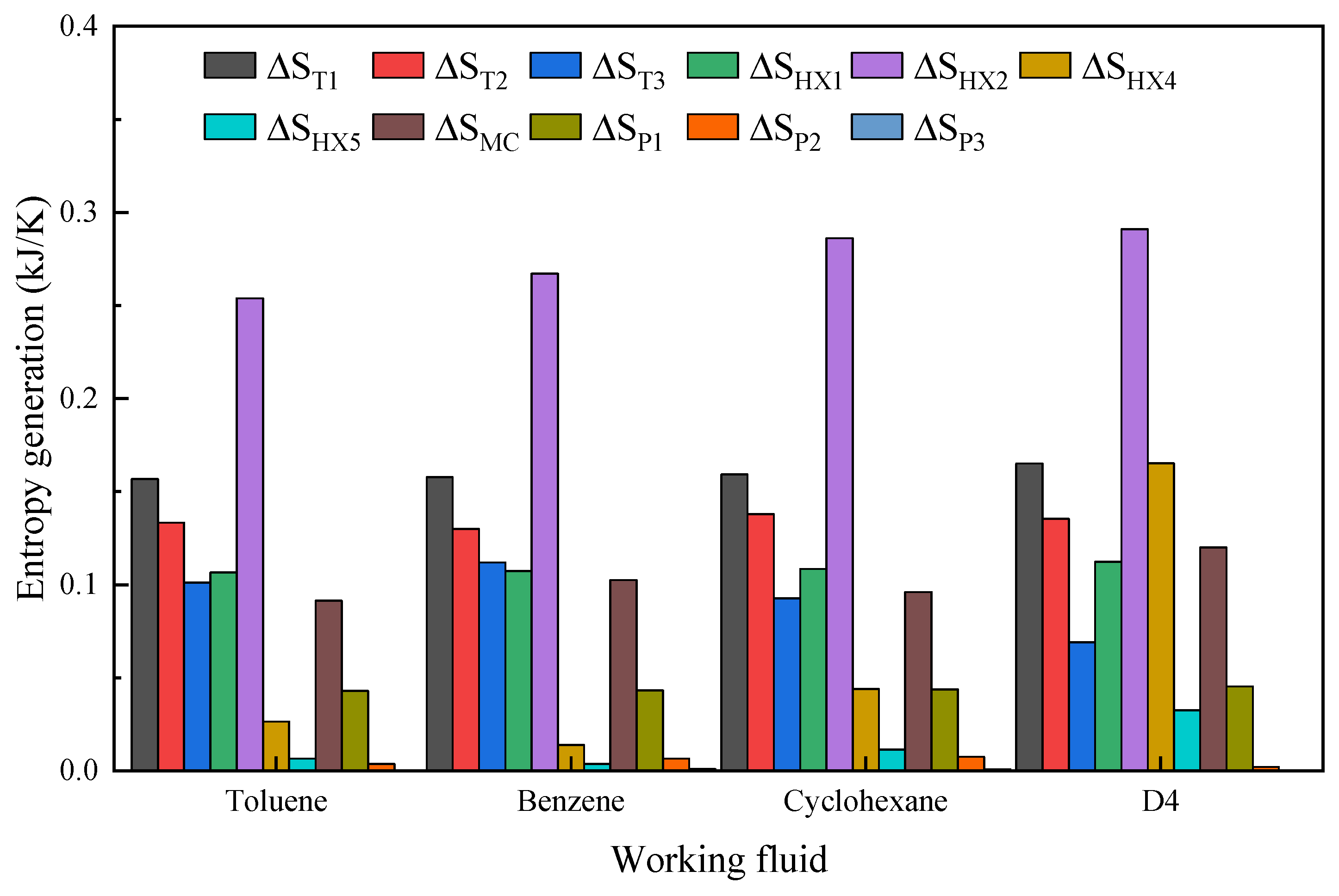
Figure 23 presents the distribution of thermodynamic losses obtained when different working fluids are adopted in the system. For all four bottom ORC working-fluid cases, HX2 exhibits the largest heat-transfer irreversibility among the system components. In HX2, the hot-side fluid is the BDO mixture discharged from the top ORC, while the cold-side fluid is the corresponding bottom ORC working fluid, namely toluene, benzene, cyclohexane, or D4. The irreversibility associated with HX2 accounts for 27.49%, 28.28%, 28.97%, and 25.58% of the total exergy loss when toluene, benzene, cyclohexane, and D4 are used, respectively.
Figure 23.
Entropy generation at optimum CORC efficiency for different working fluids.
4.2. Thermodynamic Performance of Modes 2 and 4
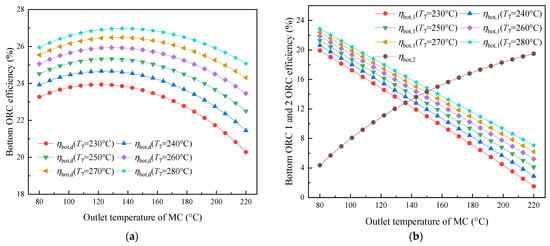
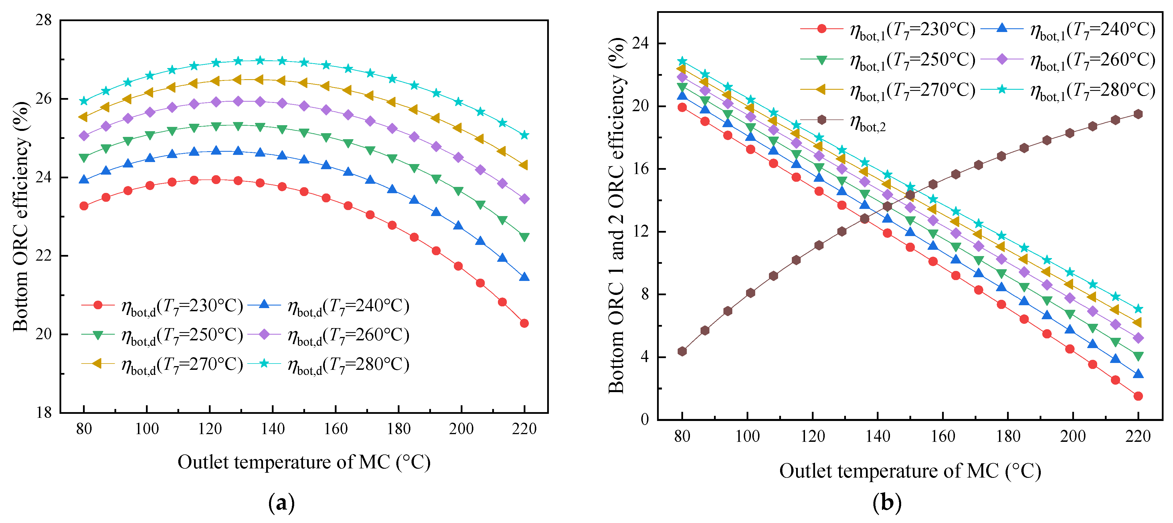
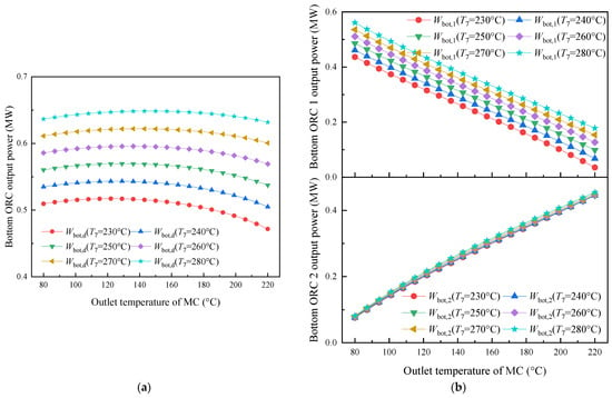
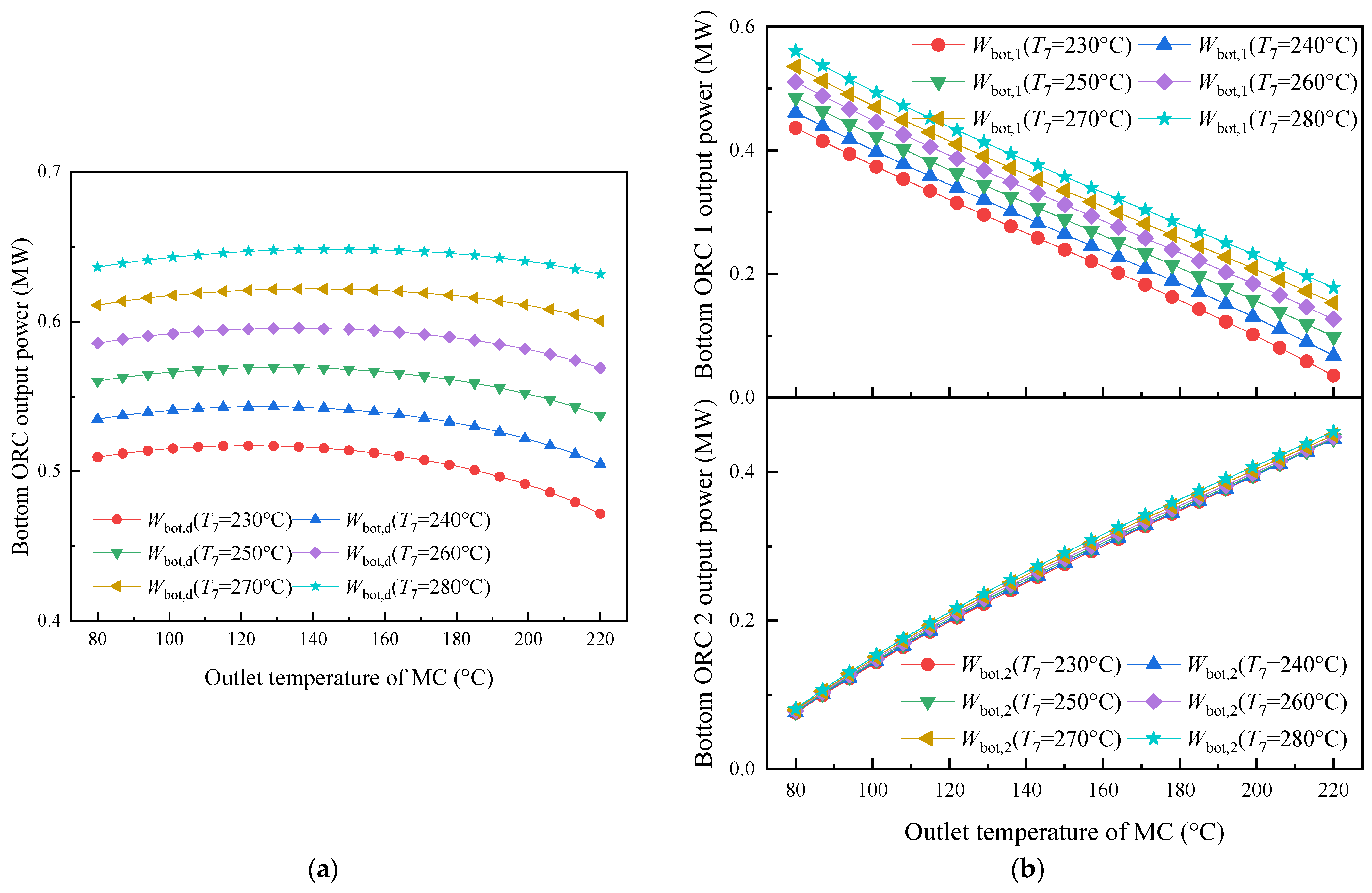
In this section, the exothermic temperature T17 of the high-temperature storage tank is set to 300 °C, and the bottom ORC circulation working fluid is toluene. Figure 24a illustrates the relationship between thermal efficiency and T7 temperature, as well as the changes in MC temperature during the heat release process in Modes 2 and 4.
Figure 24.
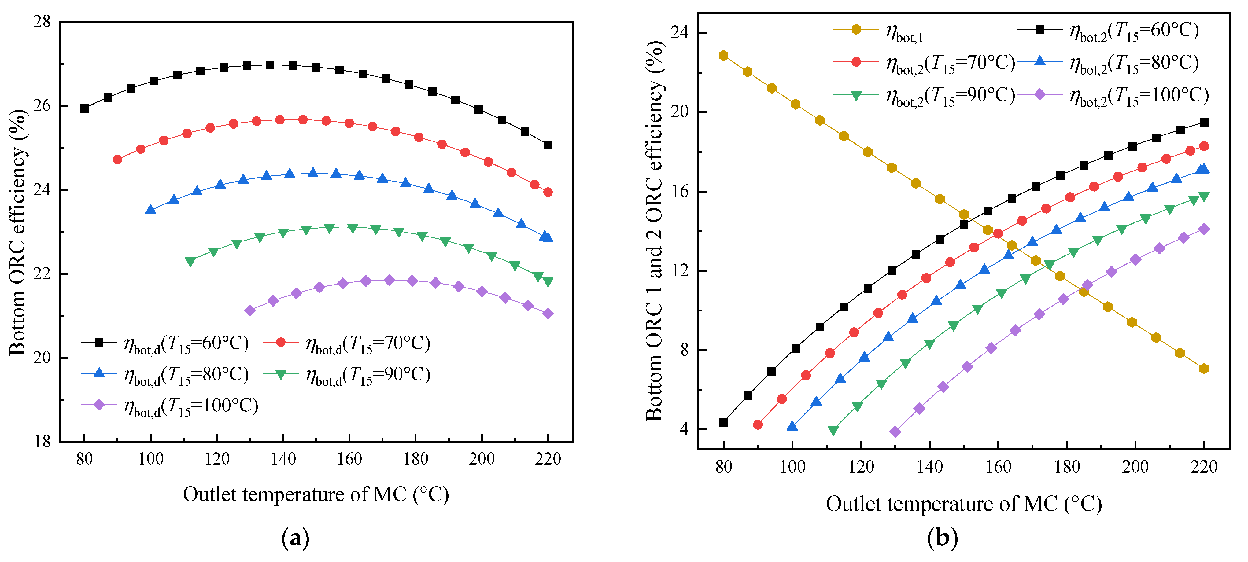
Variation in the thermal efficiency for toluene: (a) bottom ORC; (b) Bottom ORC 1 and 2.
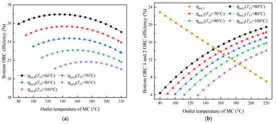
The system exhibits improved thermal efficiency as the T7 temperature is elevated. Nevertheless, for each fixed T7 condition, the influence of MC temperature is characterized by a maximum efficiency point, beyond which further temperature increases cause efficiency deterioration. This is because, as the temperature of the MC increases, the temperature difference in the bottom second-stage ORC heat exchange increases, resulting in an improvement in thermal efficiency. However, the temperature difference in the first-stage ORC heat exchange decreases, resulting in a decrease in thermal efficiency, and the two are mutually constrained. At T7 temperatures of 230 °C, 240 °C, 250 °C, 260 °C, 270 °C, and 280 °C, the maximum thermal efficiency of the bottom ORC system is recorded at 23.94%, 24.66%, 25.33%, 25.94%, 26.49%, and 26.97%, respectively. Figure 24b depicts the trends in thermal efficiency for the bottom two stages of the ORC. The thermal efficiency of the first stage of the bottom ORC system decreases as the MC temperature increases, while the thermal efficiency of the second stage increases with rising MC temperature.
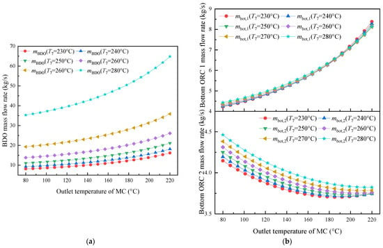
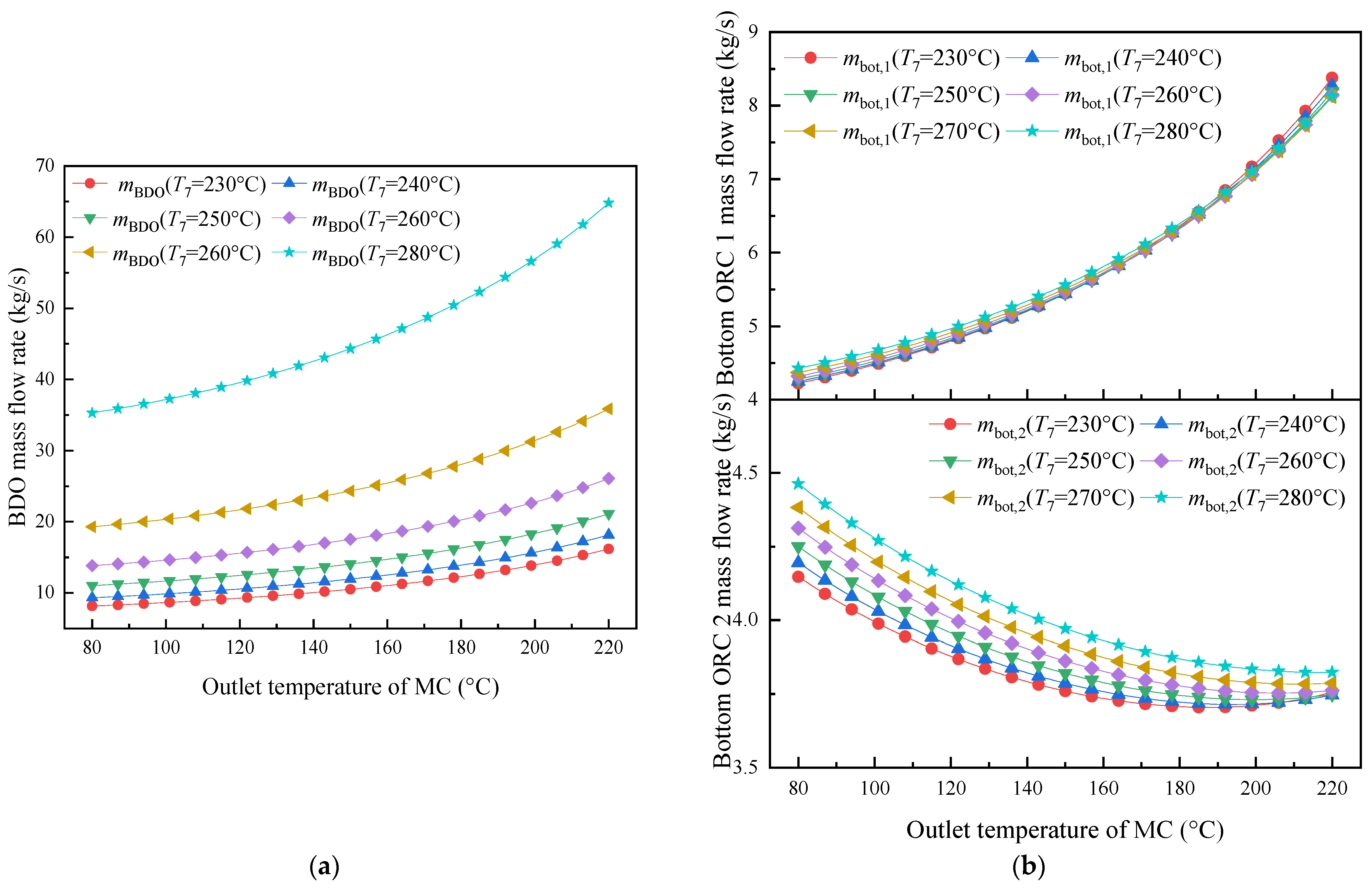
Figure 25a shows the mass flow rate of the BDO working fluid during the heat release process of the system. As T7 increases, the mass flow rate of BDO also increases. The mass flow rate of the working fluid in the first and second ORCs at the bottom is shown in Figure 25b. The mass flow rate of the first ORC at the bottom increases with the increase in MC temperature, while the opposite is true for the second ORC at the bottom.
Figure 25.
Variation in the mass flow rate: (a) BDO; (b) Bottom ORC 1 and 2 using toluene.
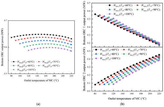
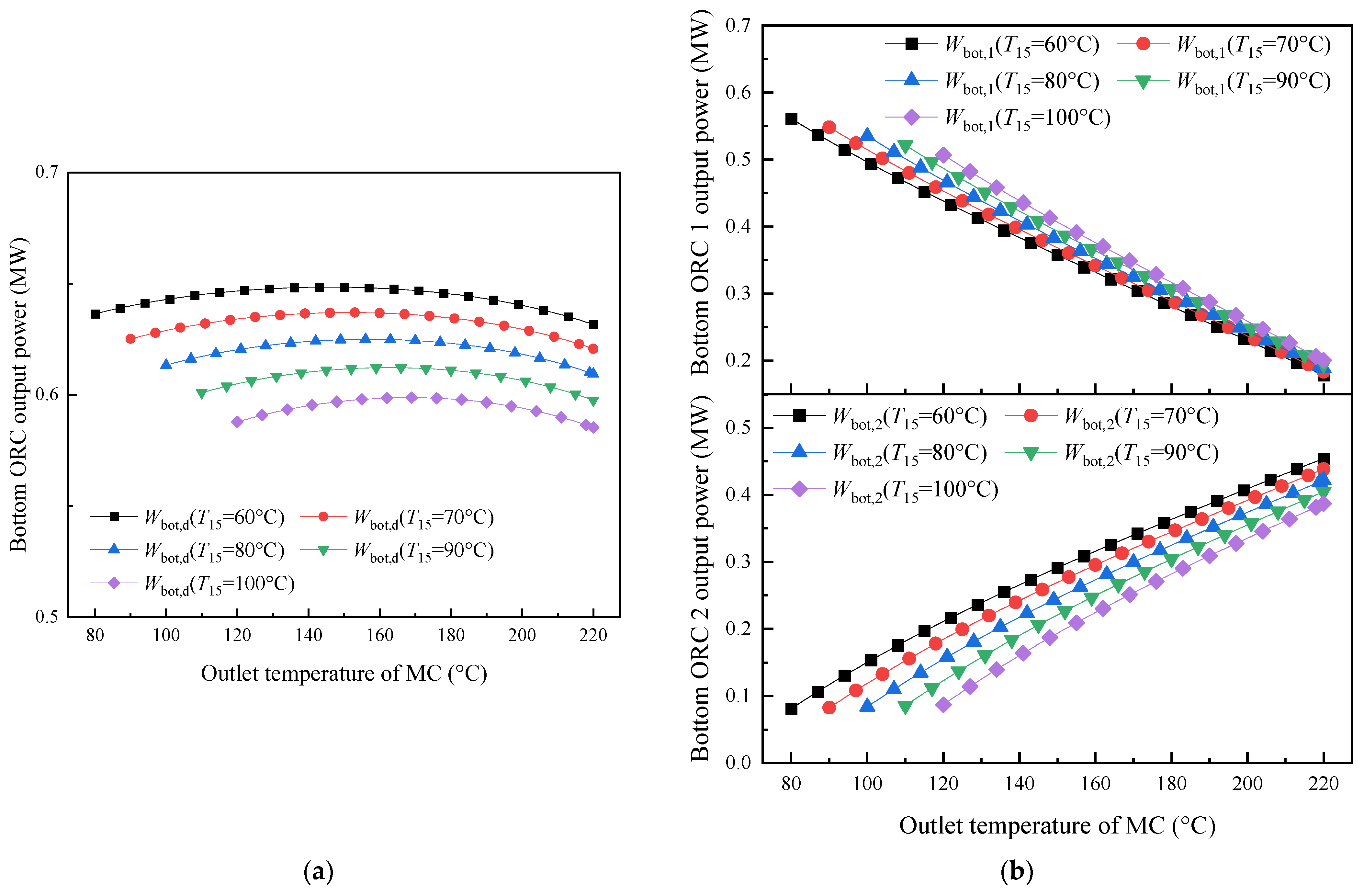
Figure 26a illustrates the variation in the output power of the bottom ORC with respect to MC temperature. The output power remains stable as the MC temperature increases. At T7 temperatures of 230 °C, 240 °C, 250 °C, 260 °C, 270 °C, and 280 °C, the maximum output power of the bottom ORC system is recorded at 0.52 MW, 0.54 MW, 0.57 MW, 0.60 MW, 0.62 MW, and 0.65 MW, respectively. Figure 26b depicts the output power for the first- and second-stage ORCs at the bottom. The first-stage ORC exhibits a downward trend in power output as the MC temperature is elevated, while the second stage exhibits an increase in output power as MC temperature rises.
Figure 26.
Variation in the power output for toluene: (a) bottom ORC; (b) Bottom ORC 1 and 2.
Table 5 presents the output power and thermal efficiency of various ORCs in the system at maximum thermal efficiency during exothermic mode. Meanwhile, Table 6 displays the parameter distribution under optimal bottom ORC efficiency in exothermic mode.
Table 5.
Parameters at maximum thermal efficiency of the system in exothermic mode.
Table 6.
Parameter distribution at optimum bottom ORC efficiency.
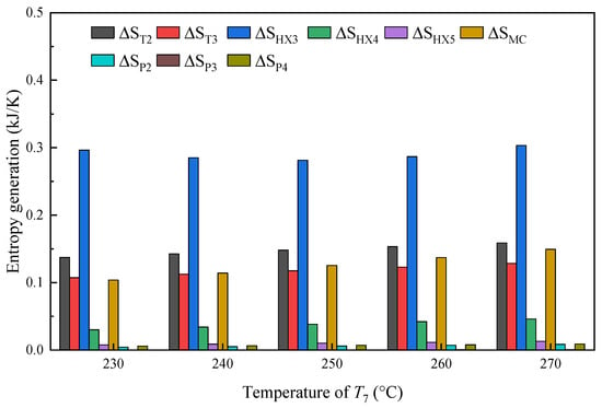
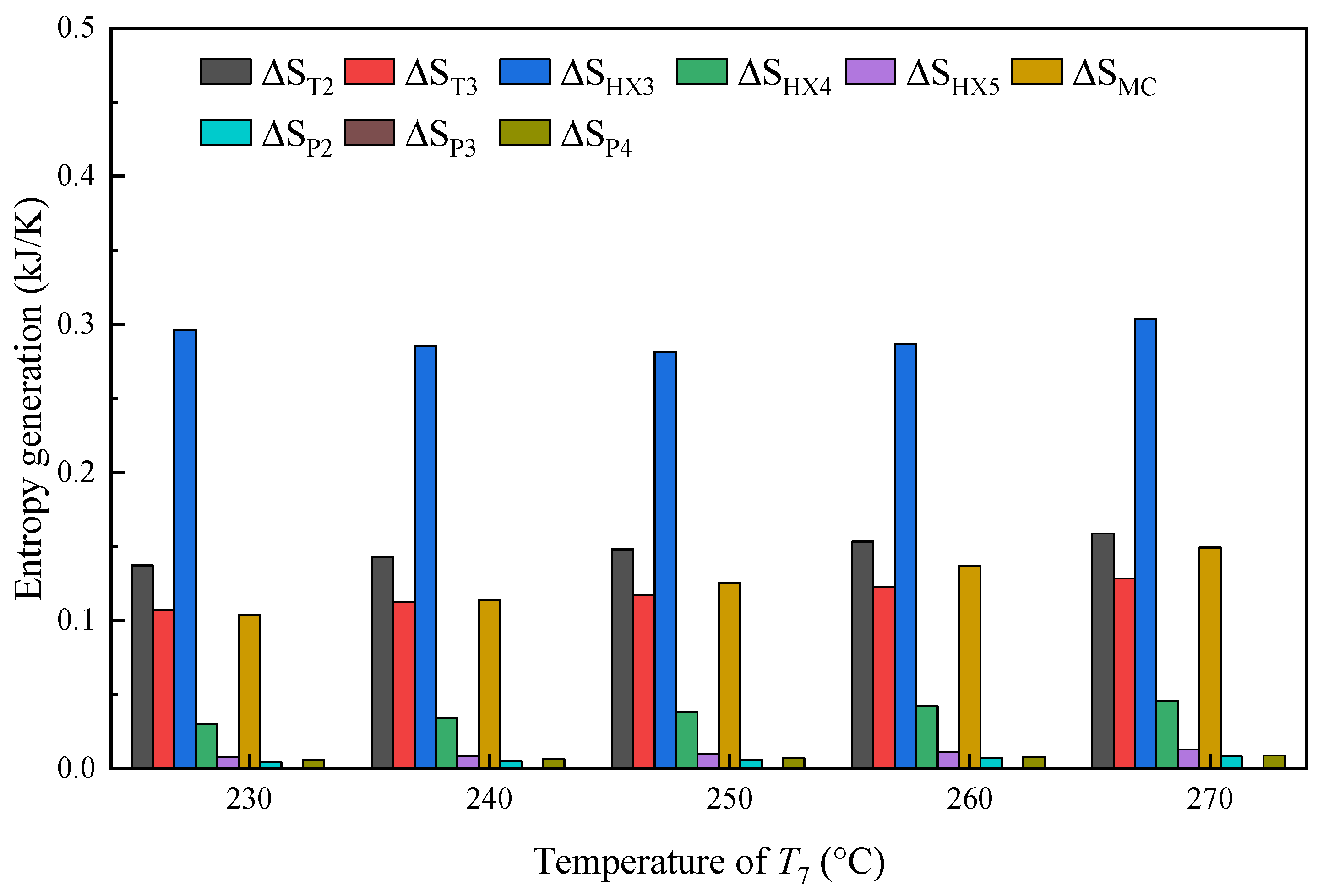
Figure 27 depicts the irreversibility behaviour of the bottom ORC under the two operating scenarios (Modes 2 and 4). The heat exchange process in HX3 between the high-temperature fluid and the bottom ORC working fluid represents the dominant source of thermal loss, accounting for 42.73%, 40.17%, 38.31%, 37.26%, and 37.12% of the total exergy loss, when T7 is 230 °C, 240 °C, 250 °C, 260 °C, and 270 °C, respectively. The exergy loss of the P4 pump accounts for approximately 1.05% of the total exergy loss. Pumps P2, P3, and P4 have little contribution to entropy generation, with values less than 1%.
Figure 27.
Entropy generation at optimum bottom ORC efficiency for toluene under different temperature of T7.
This section examines the impact of changes in condensation temperature on the system operating in exothermic mode, with T17 set at 300 °C and T7 set at 280 °C. The relationship between condenser operating conditions and CORC system efficiency is examined in Figure 28a. The imposed condensation temperature is closely linked to the external heat-rejection environment, which varies with ambient temperature. As the temperature of the MC and the condensation temperature (T15) increase, the thermal efficiency of the bottom ORC decreases in exothermic mode. When the MC is at 136 °C and T15 is at 60 °C, the bottom ORC achieves its highest efficiency of 26.97%. At condensation temperatures of 60 °C, 70 °C, 80 °C, 90 °C, and 100 °C, the bottom ORC efficiencies are 26.94%, 25.67%, 24.37%, 23.08% and 21.79%, respectively. Figure 28b presents the thermal efficiency of the two stages of the bottom ORC, showing that while the thermal efficiency of the first stage decreases, the efficiency of the second stage increases.
Figure 28.
Variation in the thermal efficiency for toluene at different condensation temperatures: (a) bottom ORC; (b) Bottom 1 and 2 ORC.
Figure 29 illustrates the output power of the bottom ORC system and the corresponding output power trends of the two-stage ORC as the condensation temperature varies in exothermic mode. The response of bottom ORC power generation to changes in T15 is evaluated in Figure 29a. An increase in T15 results in a decline in power generation, while Figure 29b illustrates the output characteristics of the individual stages within the bottom ORC system.
Figure 29.
Variation in the power output for toluene: (a) bottom ORC; (b) Bottom 1 and 2 ORC.
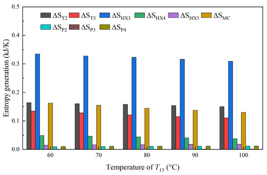
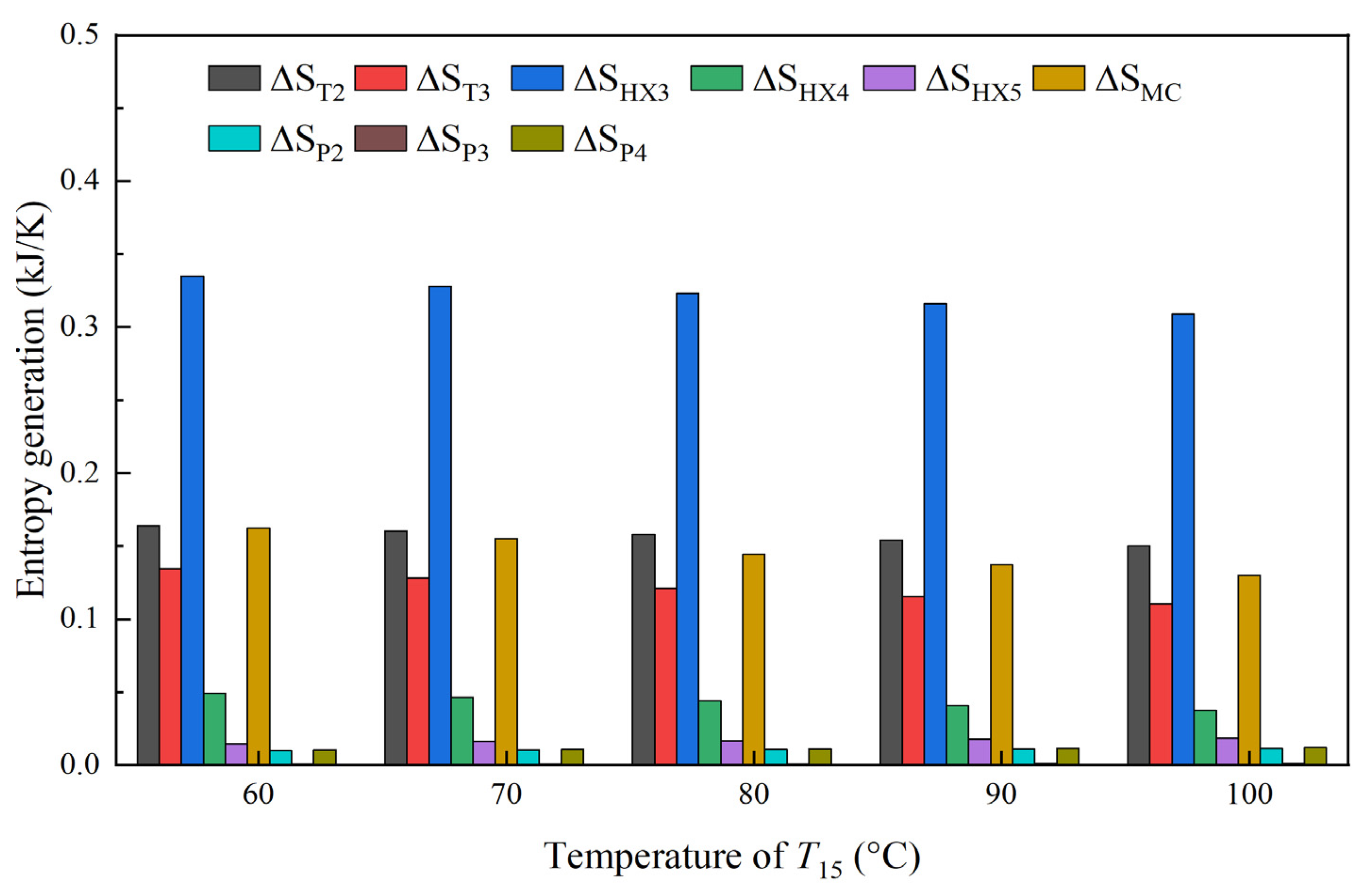
Figure 30 shows the entropy generation behaviour of the bottom ORC for the two operating modes. The heat exchange process in HX3 contributes the greatest thermodynamic loss, mainly resulting from the irreversible heat transfer between the hot-side stream and the bottom ORC fluid. At condensation temperatures of 60 °C, 70 °C, 80 °C, 90 °C, and 100 °C, the exergy losses are 0.34 kJ/K, 0.33 kJ/K, 0.32 kJ/K, 0.32 kJ/K, and 0.31 kJ/K, respectively.
Figure 30.
Entropy generation at optimum bottom ORC efficiency for toluene under different temperature of T15.
The present results can be compared with two closely related studies by the present authors. Our previous study [30] demonstrated the feasibility of direct vapour generation in a solar ORC by eliminating the intermediate heat-transfer-fluid loop, although the system mainly focused on single-cycle power generation at relatively low evaporation temperatures. In another previous study [35], a high-temperature solar CORC achieved a maximum thermal efficiency of 32.85% at a heat-source temperature of approximately 311 °C, while the efficiency exceeded 37% as the heat-source temperature approached 370 °C. In comparison, the present DVG-CORC reaches a maximum thermal efficiency of 37.67% at T1 = 400 °C and additionally recovers the low-temperature condensation heat for useful heat production. Therefore, the present configuration combines direct vapour generation and high-temperature cascade power conversion while further extending them to combined heat and power production. However, the additional cascade stages and thermal-storage subsystem also increase the complexity of the system. Since the compared systems have different heat-source temperatures and system boundaries, their reported efficiencies should not be interpreted as strictly equivalent.
4.3. System Economic Analysis
A complete power-generation system needs to undergo economic evaluation to determine whether it has good application prospects, whether it can solve the problems encountered in current research, achieve expected goals, and have good economic effects.
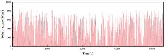
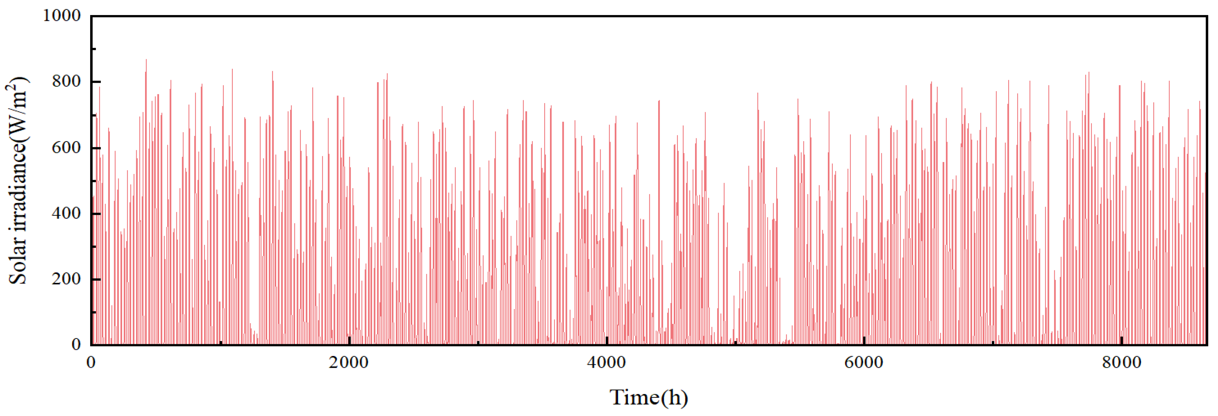
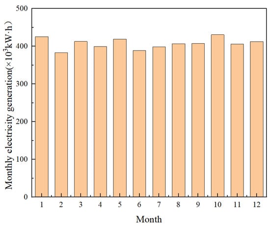
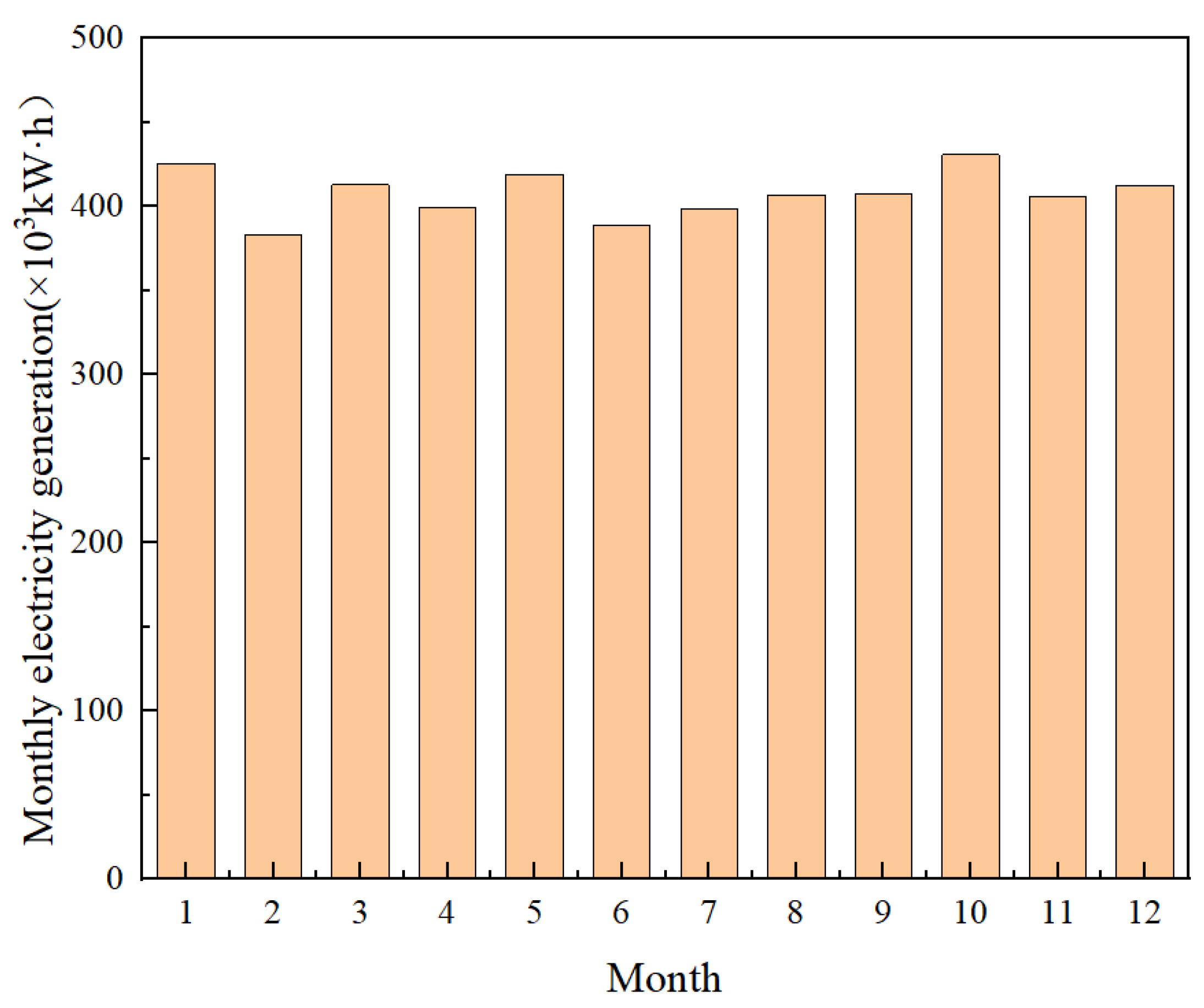
The system’s operating mode dynamically switches based on direct normal irradiance (DNI): when DNI > 450 W/m2 during the day, the system operates in Mode 1; when DNI < 450 W/m2, it operates in Mode 2. Taking Beijing as an example, when the bottom condensation temperature is 60 °C, simulations based on annual solar irradiance data (Figure 31) and corresponding system operating modes yielded the monthly power-generation distribution shown in Figure 32. The system’s annual total power generation is approximately 4.9 × 10⁶ kWh.
Figure 31.
Solar irradiance in Beijing.
Figure 32.
Monthly electricity generation of the DVG-CORC cogeneration system in Beijing.
At a condensation temperature of 60 °C, the working fluid in the final condensation stage can be utilized for building heating and daily hot-water supply, with an annually usable thermal energy output of approximately 1.4 × 10⁷ kWh. This highlights the potential of solar thermal energy as a more cost-effective renewable energy solution. Solar thermal power generation can provide better efficiency in capturing and storing thermal energy, thereby reducing overall electricity production costs.
Table 7 shows the time-of-use electricity rates for industrial and commercial users in the Beijing area [44]. The residential [45] metered heat rate is USD 0.0231/kWh. Multiplying the annual electricity generation during each time period by the corresponding time-of-use electricity tariff yields an annual electricity revenue of approximately USD 606,684. Based on an annual useful thermal-energy output of approximately 1.4 × 10⁷ kWh, the annual heating revenue is approximately USD 322,953. Therefore, the total annual revenue of the cogeneration system is approximately USD 929,637.
Table 7.
Time-of-use electricity tariffs for industrial and commercial consumers in Beijing.
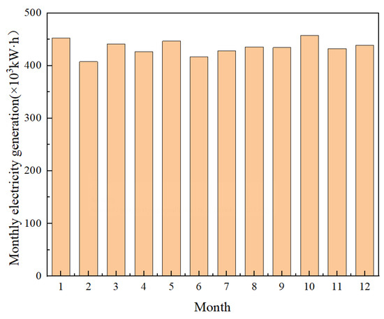
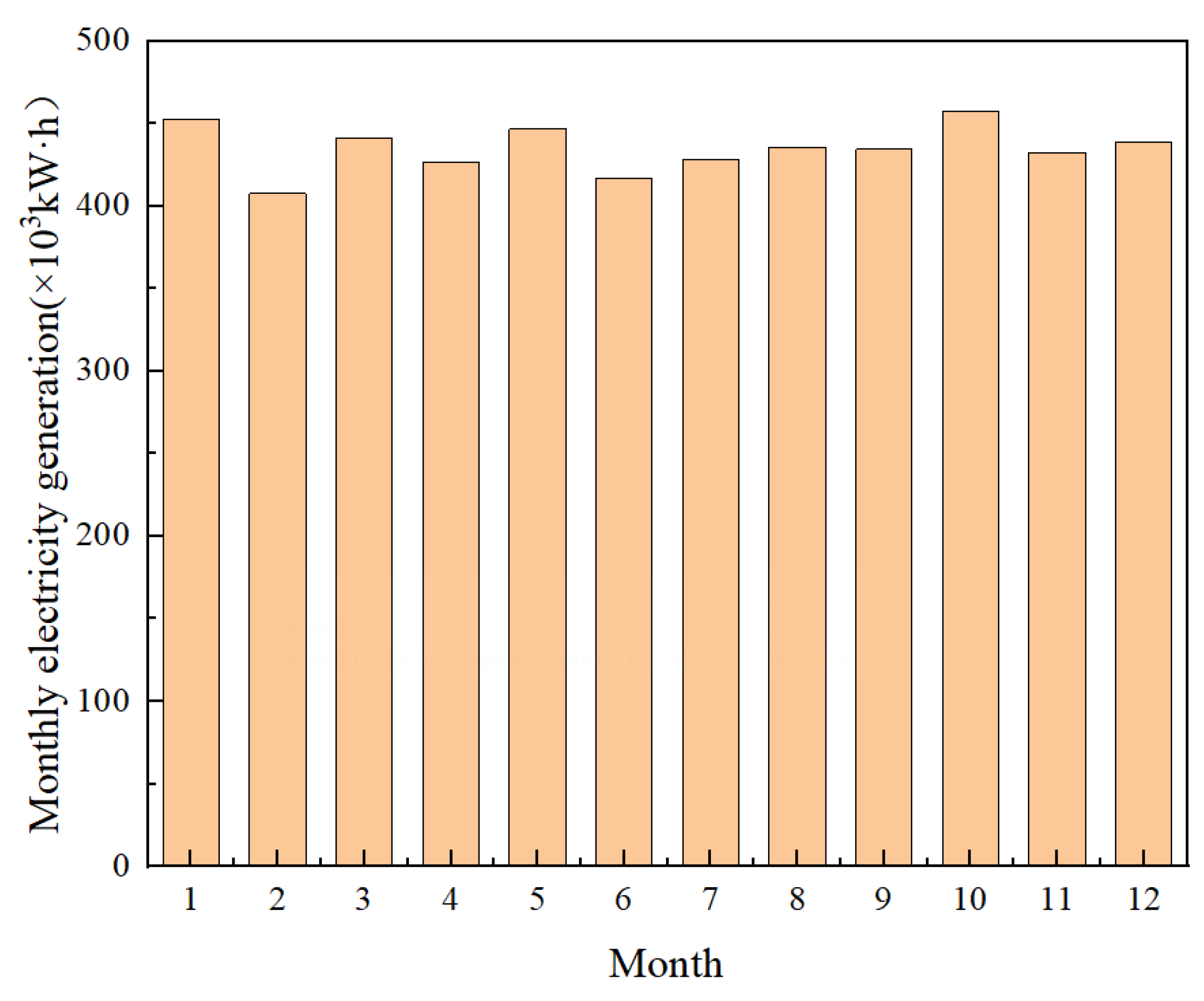
For comparison, an ORC system operating exclusively for electricity generation at a condensation temperature of 30 °C was evaluated throughout the year under the climatic and tariff conditions of Beijing, as shown in Figure 33. The annual electricity generation of the power-only system is 5.2 × 10⁶ kWh, corresponding to an annual revenue of approximately USD 645,368. The annual revenue of the cogeneration system operating at a condensation temperature of 60 °C is therefore approximately USD 284,269 higher than that of the power-only system operating at a condensation temperature of 30 °C. This economic advantage mainly results from the recovery and sale of useful low-temperature heat, which provides an additional revenue stream and improves the overall utilization of the collected solar energy.
Figure 33.
Monthly electricity generation of the DVG-CORC system without cogeneration in Beijing.
5. Conclusions
This paper presents a novel high-temperature solar energy system coupled with a DVG-CORC system to achieve combined heat and power generation. Based on changes in solar irradiance, the system can switch between different modes to provide stable power output throughout the day.
In normal mode (Mode 1), the evaporation temperature and condensation temperature of the DVG-CORC system are set to 400 °C and 60 °C. When the temperature of T7 is 220 °C and T10 is 117 °C, the maximum thermal efficiency of the CORC system is 37.67%, and the top ORC and the bottom ORC output powers are 0.51 MW and 0.49 MW, respectively. Additionally, the hot water from the condensation section can provide thermal energy. When the condensation temperature is 60 °C, 70 °C, 80 °C, 90 °C, and 100 °C, the maximum thermal efficiencies of the DVG-CORC system in Mode 1 are recorded as 37.67%, 36.52%, 35.38%, 34.24%, and 33.11%, respectively. A higher condensation temperature increases the available thermal energy but results in a trade-off of reduced system power generation. For evaporation temperatures of 350 °C, 360 °C, 370 °C, 380 °C, 390 °C and 400 °C, the CORC system achieves maximum thermal efficiencies of 34.34%, 35.06%, 35.75%, 36.41%, 37.05%, and 37.67%, respectively. In Modes 2 and 4, for evaporation temperatures of 230, 240, 250, 260, 270, and 280 °C in the bottom ORC, the maximum thermal efficiency is recorded at corresponding values of 23.94%, 24.66%, 25.33%, 25.94%, 26.49%, and 26.97%. At the condensation temperatures of 60 °C, 70 °C, 80 °C, 90 °C, and 100 °C, the bottom ORC efficiencies are 26.94%, 25.67%, 24.37%, 23.08% and 21.79%, respectively. The annual revenue of the proposed DVG-CORC cogeneration system is approximately USD 929,637, which is approximately USD 284,269 higher than that of the corresponding ORC system designed exclusively for electricity generation. The additional revenue obtained from useful heat production demonstrates the improved economic competitiveness of the proposed cogeneration configuration.
Author Contributions
Conceptualization, X.R. and L.G.; methodology, X.R. and L.G.; validation, X.R., X.M., J.L. and L.G.; formal analysis, Z.T. and Z.Z.; investigation, Z.T. and Z.Z.; resources, X.R., J.L., X.M. and L.G.; data curation, Z.T. and Z.Z.; writing—original draft preparation, Z.T. and Z.Z.; writing—review and editing, X.R., J.L., X.M. and L.G.; visualization, Z.T. and Z.Z.; supervision, X.R., J.L., X.M. and L.G.; project administration, X.R.; funding acquisition, X.R. and L.G. All authors have read and agreed to the published version of the manuscript.
Funding
The study was sponsored by the National Natural Science Foundation of China (52206292), Shandong Provincial Natural Science Foundation (ZR2024QE297), the Fundamental Research Funds for the Central Universities (No. 23CX06026A), and the Key R&D Program of Shandong province (2025RZB0805).
Institutional Review Board Statement
Not applicable.
Informed Consent Statement
Not applicable.
Data Availability Statement
All data generated or analyzed during this study are included in this article.
Acknowledgments
The authors would like to thank the support and assistance provided by their institutions and colleagues during the development of this study.
Conflicts of Interest
Author Xiaolei Mou is employed by Daya Bay Nuclear Power Operations and Management Co., Ltd. The remaining authors declare that the research was conducted in the absence of any commercial or financial relationships that could be construed as potential conflicts of interest.
Nomenclature
| Symbol/Abbreviation | Definition | Unit |
| BDO | Biphenyl and diphenyl oxide mixture | — |
| CSP | Concentrated solar power | — |
| DVG-CORC | Direct vapour generation cascade organic Rankine cycle | — |
| CORC | Cascade organic Rankine cycle | — |
| ORC | Organic Rankine cycle | — |
| DNI | Direct normal irradiance | W/m2 |
| HX | Heat exchanger | — |
| MC | Mixing chamber (mixing heater) | — |
| MT | Medium-temperature storage tank | — |
| LT | Low-temperature storage tank | — |
| HP | High-pressure | — |
| PV | Photovoltaic | — |
| PTC | Parabolic-trough collector | — |
| Ce | Electricity tariff | USD/kWh |
| Ch | Heating tariff | USD/kWh |
| h | Specific enthalpy | kJ/kg |
| m | Mass flow rate | kg/s |
| p | Pressure | kPa |
| Q | Heat-transfer rate | kW |
| s | Specific entropy | kJ/(kg K) |
| T | Temperature | °C or K |
| TEHST | Equivalent hot-side temperature | K |
| v | Specific volume | m3/kg |
| W | Power | kW or MW |
| ΔTmin | Minimum heat-exchanger temperature difference | K |
| η | Thermal efficiency | % |
| εT | Expander isentropic efficiency | % |
| εP | Pump isentropic efficiency | % |
| εg | Generator efficiency | % |
| εr | Regenerator effectiveness | % |
| top | Subscript for the top ORC | — |
| bot | Subscript for the bottom ORC | — |
| 1 | Subscript for Bottom ORC 1 | — |
| 2 | Subscript for Bottom ORC 2 | — |
| s | Subscript for an isentropic state | — |
| max | Subscript for the maximum value | — |
References
- Ji, J.; Tang, H.; Jin, P. Economic potential to develop concentrating solar power in China: A provincial assessment. Renew. Sustain. Energy Rev. 2019, 114, 109279. [Google Scholar] [CrossRef] [Scilit]
- Shi, L.; Wang, X.; Hu, Y.; He, Y.; Yan, Y. Solar-thermal conversion and steam generation: A review. Appl. Therm. Eng. 2020, 179, 115691. [Google Scholar] [CrossRef] [Scilit]
- Mistarihi, M.Z.; Magableh, G.M.; Abu Dalu, S.M. A Hybrid Solar–Thermoelectric System Incorporating Molten Salt for Sustainable Energy Storage Solutions. Technologies 2025, 13, 104. [Google Scholar] [CrossRef] [Scilit]
- Pascual, S.; Lisbona, P.; Romeo, L.M. Thermal Energy Storage in Concentrating Solar Power Plants: A Review of European and North American R&D Projects. Energies 2022, 15, 8570. [Google Scholar] [CrossRef] [Scilit]
- Romero, M.; González-Aguilar, J. Solar thermal CSP technology. WIREs Energy Environ. 2014, 3, 42–59. [Google Scholar] [CrossRef] [Scilit]
- Kazaz, O.; Abu-Nada, E. Exploiting light–matter interactions in multifunctional nanocomposite core–shell materials for advanced utilization of full-spectrum solar energy. Energy Convers. Manag. 2025, 343, 120210. [Google Scholar] [CrossRef] [Scilit]
- Hazmoune, M.; Debbache, M.; Osman, M.G.; Aour, B.; Panait, C.; Laissaoui, M.; Lazaroiu, G. Modeling and Efficiency Analysis of an Immersed Heat Exchanger for Solar-Powered Industrial Heat Processes: A Case Study on Wool Washing. Technologies 2025, 13, 308. [Google Scholar] [CrossRef] [Scilit]
- Ghasemiasl, R.; Dehghanizadeh, H.; Javadi, M.A.; Abdolmaleki, M. 4E Transient Analysis of a Solar-Hybrid Gas-Turbine Cycle Equipped with Heliostat and MED. Sustainability 2023, 15, 8792. [Google Scholar] [CrossRef] [Scilit]
- Sarvar-Ardeh, S.; Rashidi, S.; Rafee, R.; Li, G. Recent advances in the applications of solar-driven co-generation systems for heat, freshwater and power. Renew. Energy 2024, 225, 120256. [Google Scholar] [CrossRef] [Scilit]
- Bošnjaković, M. Analysis of Concentrated Solar Power Potential in the Photovoltaic Competitive Landscape. Technologies 2025, 13, 554. [Google Scholar] [CrossRef] [Scilit]
- Liu, T.; Yang, J.; Yang, Z.; Duan, Y. Techno-economic feasibility of solar power plants considering PV/CSP with electrical/thermal energy storage system. Energy Convers. Manag. 2022, 255, 115308. [Google Scholar] [CrossRef] [Scilit]
- Li, N.; Wu, Y.; Lei, B.; Zhang, C.; Lu, Y.; Ren, L. Dynamic optimization and thermo-economic assessment of a solar parabolic trough combined heat and power system with thermal storage: A case study. Appl. Therm. Eng. 2023, 235, 121372. [Google Scholar] [CrossRef] [Scilit]
- Kee, Z.; Wang, Y.; Pye, J.; Rahbari, A. Small-scale concentrated solar power system with thermal energy storage: System-level modelling and techno-economic optimisation. Energy Convers. Manag. 2023, 294, 117551. [Google Scholar] [CrossRef] [Scilit]
- Zurita, A.; Mata-Torres, C.; Valenzuela, C.; Felbol, C.; Cardemil, J.M.; Guzmán, A.M.; Escobar, R.A. Techno-economic evaluation of a hybrid CSP + PV plant integrated with thermal energy storage and a large-scale battery energy storage system for base generation. Sol. Energy 2018, 173, 1262–1277. [Google Scholar] [CrossRef] [Scilit]
- Almatrafi, E.; Khaliq, A.; Kumar, R.; Bamasag, A.; Siddiqui, M.E. Proposal and Investigation of a New Tower Solar Collector-Based Trigeneration Energy System. Sustainability 2023, 15, 7474. [Google Scholar] [CrossRef] [Scilit]
- Borunda, M.; Jaramillo, O.A.; Dorantes, R.; Reyes, A. Organic Rankine Cycle coupling with a Parabolic Trough Solar Power Plant for cogeneration and industrial processes. Renew. Energy 2016, 86, 651–663. [Google Scholar] [CrossRef] [Scilit]
- Zhang, H.; Lei, B.; Yu, T.; Zhao, Z. Form and Operation Mode Analysis of a Novel Solar-Driven Cogeneration System with Various Collector Types. Int. J. Photoenergy 2019, 2019, 5329086. [Google Scholar] [CrossRef] [Scilit]
- Allan, G.; Eromenko, I.; Gilmartin, M.; Kockar, I.; McGregor, P. The economics of distributed energy generation: A literature review. Renew. Sustain. Energy Rev. 2015, 42, 543–556. [Google Scholar] [CrossRef] [Scilit]
- Zhang, N.; Xu, P.; Wang, Y.; Tong, W.; Yang, Z. Performance Analysis and Comprehensive Evaluation of Solar Organic Rankine Cycle Combined with Transcritical CO2 Refrigeration Cycle. Energies 2023, 16, 5557. [Google Scholar] [CrossRef] [Scilit]
- Pina, E.A.; Lozano, M.A.; Serra, L.M.; Hernández, A.; Lázaro, A. Design and thermoeconomic analysis of a solar parabolic trough–ORC–biomass cooling plant for a commercial center. Sol. Energy 2021, 215, 92–107. [Google Scholar] [CrossRef] [Scilit]
- Boyko, E.; Byk, F.; Myshkina, L.; Nasibova, E.; Ilyushin, P. Enhancement of Building Heating Systems Connected to Third-Generation Centralized Heating Systems. Technologies 2026, 14, 56. [Google Scholar] [CrossRef] [Scilit]
- Jensen, A.R.; Sifnaios, I.; Perers, B.; Holst Rothmann, J.; Mørch, S.D.; Jensen, P.V.; Dragsted, J.; Furbo, S. Demonstration of a concentrated solar power and biomass plant for combined heat and power. Energy Convers. Manag. 2022, 271, 116207. [Google Scholar] [CrossRef] [Scilit]
- Matuszewska, D. Solar Organic Rankine Cycle (ORC) Systems: A Review of Technologies, Parameters, and Applications. Energies 2024, 17, 5106. [Google Scholar] [CrossRef] [Scilit]
- Mariñes Delgado, L.M.; Chumpitaz Ayala, G.R.; Mendiburu, A.Z. Technical-economic evaluation of application scenarios of an Organic Rankine Cycle (ORC) as a solution to the cogeneration deficit in a sugar plant. Energy 2024, 313, 133785. [Google Scholar] [CrossRef] [Scilit]
- Pina, E.A.; Serra, L.M.; Lozano, M.A.; Hernández, A.; Lázaro, A. Comparative Analysis and Design of a Solar-Based Parabolic Trough–ORC Cogeneration Plant for a Commercial Center. Energies 2020, 13, 4807. [Google Scholar] [CrossRef] [Scilit]
- Rahmdel, M.; Behzadmehr, A.; Sadeghi, J.; Farzaneh, H.; Sarhaddi, F. Conceptual design of an innovative flexible and controllable Solar ORC cogeneration system for operating in remote areas. Sol. Energy 2023, 262, 111899. [Google Scholar] [CrossRef] [Scilit]
- Wang, L.; Yang, J.; Qu, B.; Pang, C. Multi-Objective Optimization of an Organic Rankine Cycle (ORC) for a Hybrid Solar–Waste Energy Plant. Energies 2024, 17, 1810. [Google Scholar] [CrossRef] [Scilit]
- Desai, N.B.; Bandyopadhyay, S. Thermo-economic analysis and selection of working fluid for solar organic Rankine cycle. Appl. Therm. Eng. 2016, 95, 471–481. [Google Scholar] [CrossRef] [Scilit]
- Jiménez-Arreola, M.; Wieland, C.; Romagnoli, A. Direct vs indirect evaporation in Organic Rankine Cycle (ORC) systems: A comparison of the dynamic behavior for waste heat recovery of engine exhaust. Appl. Energy 2019, 242, 439–452. [Google Scholar] [CrossRef] [Scilit]
- Vishwakarma, S.; Debnath, B.K.; Debnath, K.; Das, B. Comparative Analysis of Absorber Tubes of Parabolic Trough Solar Collector Using Therminol VP-1 as Heat Transfer Fluid. In Advances in Mechanical Engineering; Biswal, B.B., Sarkar, B.K., Mahanta, P., Eds.; Springer: Singapore, 2020; pp. 1227–1240. [Google Scholar] [CrossRef] [Scilit]
- Li, J.; Alvi, J.Z.; Pei, G.; Ji, J.; Li, P.; Fu, H. Effect of working fluids on the performance of a novel direct vapor generation solar organic Rankine cycle system. Appl. Therm. Eng. 2016, 98, 786–797. [Google Scholar] [CrossRef] [Scilit]
- Eastman Chemical Company. Therminol VP-1 Heat Transfer Fluid. Available online: https://www.eastman.com/content/dam/eastman/corporate/en/literature/t/tf9141.pdf (accessed on 20 April 2026).
- Li, J.; Alvi, J.Z.; Pei, G.; Su, Y.; Li, P.; Gao, G.; Ji, J. Modelling of organic Rankine cycle efficiency with respect to the equivalent hot side temperature. Energy 2016, 115, 668–683. [Google Scholar] [CrossRef] [Scilit]
- Wang, X.; Wang, R.; Jin, M.; Shu, G.; Tian, H.; Pan, J. Control of superheat of organic Rankine cycle under transient heat source based on deep reinforcement learning. Appl. Energy 2020, 278, 115637. [Google Scholar] [CrossRef] [Scilit]
- Freeman, J.; Hellgardt, K.; Markides, C.N. An assessment of solar-powered organic Rankine cycle systems for combined heating and power in UK domestic applications. Appl. Energy 2015, 138, 605–620. [Google Scholar] [CrossRef] [Scilit]
- Martire, R.N.M.; Erguvan, M.; Amini, S. A 4E Analysis of a Solar Organic Rankine Cycle Applied to a Paint Shop in the Automotive Industry. Energies 2024, 17, 4291. [Google Scholar] [CrossRef] [Scilit]
- Ren, X.; Li, J.; Gao, G.; Pei, G. An innovative concentrated solar power system driven by high-temperature cascade organic Rankine cycle. J. Energy Storage 2022, 52, 104999. [Google Scholar] [CrossRef] [Scilit]
- Siddiqui, M.E.; Almatrafi, E.; Saeed, U.; Taimoor, A.A. Selection of Organic Fluid Based on Exergetic Performance of Subcritical Organic Rankine Cycle (ORC) for Warm Regions. Energies 2023, 16, 5149. [Google Scholar] [CrossRef] [Scilit]
- Song, J.; Gu, C.-W. Parametric analysis of a dual loop Organic Rankine Cycle (ORC) system for engine waste heat recovery. Energy Convers. Manag. 2015, 105, 995–1005. [Google Scholar] [CrossRef] [Scilit]
- Yağlı, H.; Koç, Y.; Kalay, H. Optimisation and exergy analysis of an organic Rankine cycle (ORC) used as a bottoming cycle in a cogeneration system producing steam and power. Sustain. Energy Technol. Assess. 2021, 44, 100985. [Google Scholar] [CrossRef] [Scilit]
- Lyu, L.; Chen, W.; Kan, A.; Zhang, Y.; Xue, S.; Zeng, J. Investigation of a Dual-Loop ORC for the Waste Heat Recovery of a Marine Main Engine. Energies 2022, 15, 8365. [Google Scholar] [CrossRef] [Scilit]
- Thol, M.; Javed, M.A.; Baumhögger, E.; Span, R.; Vrabec, J. Thermodynamic Properties of Dodecamethylpentasiloxane, Tetradecamethylhexasiloxane, and Decamethylcyclopentasiloxane. Ind. Eng. Chem. Res. 2019, 58, 9617–9635. [Google Scholar] [CrossRef] [Scilit]
- Yu, G.; Shu, G.; Tian, H.; Wei, H.; Liang, X. Multi-approach evaluations of a cascade-Organic Rankine Cycle (C-ORC) system driven by diesel engine waste heat: Part B: Techno-economic evaluations. Energy Convers. Manag. 2016, 108, 596–608. [Google Scholar] [CrossRef] [Scilit]
- State Grid Beijing Electric Power Co. State Grid Beijing Electric Power Company Agent Purchasing Electricity Price List for Industrial and Commercial Users, Implementation Period: 1–30 November 2025; State Grid Beijing Electric Power Co.: Beijing, China, 2025. [Google Scholar]
- Beijing Municipal People’s Government. What Is the Standard for Central Heating Fees in This City? Available online: https://www.beijing.gov.cn/fwcj/jiage/ggfw1/65baf72e11a82834a8639558.html (accessed on 20 April 2026).

Disclaimer/Publisher’s Note: The statements, opinions and data contained in all publications are solely those of the individual author(s) and contributor(s) and not of MDPI and/or the editor(s). MDPI and/or the editor(s) disclaim responsibility for any injury to people or property resulting from any ideas, methods, instructions or products referred to in the content. |
© 2026 by the authors. Licensee MDPI, Basel, Switzerland. This article is an open access article distributed under the terms and conditions of the Creative Commons Attribution (CC BY) license.