


Abstract
Electric-vehicle gearboxes remain key design elements because they determine how motor speed and torque are converted into wheel speed and tractive effort over a driving cycle. This design-oriented scoping review synthesizes EV gearbox architectures, gear ratio selection, efficiency losses, NVH, planetary and compound planetary systems, lubrication, thermal behavior, reliability, manufacturability, and cost within one evidence-informed architecture-selection perspective. A structured search of Scopus, IEEE Xplore, ScienceDirect, SpringerLink, and MDPI identified 312 records; after removal of 71 duplicates, screening of 241 titles and abstracts, and full-text assessment of 61 articles, 40 sources formed the reproducible structured-search core. A gap-directed supplementary search then added 12 sources in underrepresented areas, producing a 52-source synthesis set. The revised analysis reports publication trends, evidence-level distributions, technical-focus frequencies, and a dimension-separated evidence-count table for ratio count, gear train topology, and integration level. The evidence indicates that single-speed reduction gearboxes remain the mature baseline for many passenger EVs, whereas two-speed, multi-speed, planetary, compound planetary, and integrated e-axle solutions require application-specific justification based on system-level benefits and risks. An illustrative screening calculation demonstrates the framework logic without being presented as production-level validation. The principal gaps are experimentally validated loss and NVH maps, coupled efficiency–thermal–lubrication–durability analysis, reliability-aware mission-profile validation, standardized benchmarks, and transparent comparison of compound planetary and integrated e-axle systems. Across heterogeneous study conditions, reported energy benefits range from 2.4% for fixed-ratio optimization to 15% for selected multi-speed comparisons; these results are not pooled because the vehicles, motor maps, drive cycles, loss models, and validation methods differ.
1. Introduction
Electric vehicles have changed the role of the transmission system. Traction motors provide high torque at low speed and operate over wide speed ranges, allowing many battery electric vehicles (BEVs) to use a single-speed reduction gearbox. Nevertheless, the gearbox remains a critical design element because it determines how motor speed and torque are converted into wheel speed and tractive effort. It therefore affects acceleration, gradeability, maximum speed, motor operating points, energy consumption, packaging, NVH, reliability, and cost [1,2,3].
Single-speed gearboxes are mature, compact, reliable, and relatively inexpensive, but a fixed ratio always involves a compromise. A higher reduction ratio improves launch and gradeability but increases motor speed during highway operation. A lower ratio supports maximum vehicle speed but reduces low-speed tractive effort. Two-speed and multi-speed transmissions can improve motor-map utilization in demanding applications, but their benefits must exceed the penalties associated with additional losses, mass, shift complexity, NVH, durability, and cost [3,4,5,6,7,8].
Architecture selection also depends on gear train topology and integration level. Parallel-axis gearboxes are mature and economical. Planetary gearboxes offer compact coaxial packaging and high torque density, but their performance depends on load sharing, planet-bearing loads, carrier stiffness, lubrication, tolerances, and NVH [5,9,10]. Compound planetary systems provide higher ratio density but require stronger validation. Direct-drive systems eliminate the gearbox, whereas integrated e-axles combine the motor, gearbox, differential, inverter, cooling system, lubricant, and housing within one module [11].
Existing reviews address multi-speed BEV transmissions, two-speed topologies, drivetrain efficiency, gear count, and EV NVH [3,4,6,7,8,12,13,14,15]. However, the literature remains fragmented across performance, efficiency, NVH, and mechanical design topics. This review therefore connects gear ratio design, architecture selection, loss mechanisms, NVH, planetary systems, lubrication, thermal constraints, reliability, manufacturability, and future development within one evidence-informed framework while explicitly identifying areas where evidence remains limited.
The central question is therefore which EV gearbox architecture best satisfies the combined performance, efficiency, NVH, packaging, thermal, lubrication, reliability, manufacturability, and cost requirements of a specific application? To address this question, the review classifies EV gearbox technologies, synthesizes ratio design and architecture-selection methods, describes the maturity and limitations of the available evidence, and identifies the research required to justify more complex solutions.
1.1. Contribution of the Manuscript
The review distinguishes between established engineering knowledge summarized from prior studies and the original synthesis developed here. Established knowledge includes vehicle-level sizing relations, ratio-selection methods, gearbox loss mechanisms, NVH excitation mechanisms, planetary load sharing, lubrication, thermal management, and component-level reliability.
The original outputs of this review are:
- (i)
- A four-dimensional taxonomy that separates ratio count, gear train topology, shaft arrangement, and integration level;
- (ii)
- A monochrome descriptive evidence profile and a dimension-separated evidence-count table for the 52-source synthesis set;
- (iii)
- An evidence-informed architecture-selection matrix that combines performance, efficiency, NVH, thermal–lubrication behavior, reliability, manufacturability, packaging, and cost;
- (iv)
- An operational definition of the criteria required for application-specific screening;
- (v)
- An illustrative calculation and research roadmap that show how the synthesis can guide preliminary design decisions.
The reproducible structured-search core contains 40 sources. Twelve targeted supplementary sources were retained to strengthen predefined gaps in lubrication and e-fluids, churning and windage, compact-EDU thermal behavior, planetary load sharing, compound planetary validation, and durability. The supplement was gap-directed and iterative. Its query families, retained references, gaps addressed, and inclusion rationales are reported in the Supplementary Materials; exact historical query-level hit and screening counts were not retained. The supplement is therefore transparent and auditable at the query-family and retained-source level, but it is not a second complete PRISMA stream.
Accordingly, the novelty of the review lies in integrating previously separated evidence into a transparent architecture-selection structure and in showing which conclusions are mature, conditional, or weakly validated.
1.2. Organization of the Paper
The remainder of the paper is organized as follows. Section 2 describes the search strategy, eligibility criteria, structured screening, targeted supplementation, data extraction, and evidence classification. Section 3 positions the review relative to existing EV transmission surveys. Section 4 defines vehicle- and drivetrain-level design requirements. Section 5 presents the architecture taxonomy and application-oriented comparisons. Section 6 examines gear ratio design and optimization. Section 7 and Section 8 address efficiency and NVH, respectively. Section 9 focuses on planetary and compound planetary systems, while Section 10 discusses materials, manufacturing, lubrication, thermal management, and reliability. Section 11 integrates these topics into an architecture-selection framework and an illustrative screening calculation. Section 12 and Section 13 present research gaps, future directions, and limitations, and Section 14 concludes the review. Detailed source coding, targeted-search traceability, and the expanded roadmap are provided in the Supplementary Materials.
2. Review Methodology
This review adopted a systematic scoping approach adapted to an engineering design problem. PRISMA-ScR principles were used to structure identification, screening, eligibility assessment, and reporting. The completed PRISMA-ScR checklist is provided in Supplementary Table S5. The review was not registered because it does not perform a clinical or statistical meta-analysis. The aim was to identify evidence relevant to EV gearbox architecture, ratio design, efficiency, NVH, planetary and compound planetary systems, lubrication, thermal behavior, reliability, and system integration. The study should therefore be interpreted as a design-oriented scoping synthesis rather than as an exhaustive bibliometric review of the entire EV drivetrain literature.
2.1. Search Strategy and Databases
The final structured database search, illustrated in Table 1, was performed on 24 June 2026 in Scopus, IEEE Xplore, ScienceDirect, SpringerLink, and MDPI. English-language journal and conference publications from 2010 to 2026 were considered. Older sources were used only when they provided foundational mechanical design relations or standards and were not counted as part of the structured EV gearbox corpus.
Table 1.
Database-specific search strings and initial record counts used in the review methodology.
In Scopus, the search was applied to titles, abstracts, and keywords. The equivalent searchable fields and available filters were used in IEEE Xplore, ScienceDirect, SpringerLink, and MDPI. Syntax was adapted to each interface while preserving the same logical blocks: electric-vehicle context, gearbox or transmission architecture, and design-performance topics. The 40-source structured core was selected using the predefined eligibility criteria and relevance to the review question, not citation count or database ranking.
2.2. Eligibility Criteria
Eligibility was assessed using the criteria in Table 2. Peer-reviewed original research and technically detailed conference papers formed the principal evidence base. Reviews, preprints, SAE or industry papers, standards, and technical publications were used only when they supplied directly relevant context, methods, definitions, or emerging evidence. These source types were therefore distinguished explicitly rather than treated as equivalent forms of validation.
Table 2.
Inclusion and exclusion criteria used during title/abstract screening and full-text eligibility assessment.
2.3. Screening Process
The structured screening comprised four stages: identification, duplicate removal, title-and-abstract screening, and full-text eligibility assessment. The database searches returned 312 records: Scopus (n = 110), IEEE Xplore (n = 68), ScienceDirect (n = 74), SpringerLink (n = 38), and MDPI (n = 22). DOI matching, title matching, author–year comparison, and manual inspection removed 71 duplicates, leaving 241 records. Title-and-abstract screening excluded 180 records that were outside the EV gearbox mechanical design scope or had insufficient drivetrain relevance. The remaining 61 full texts were assessed against Table 2, and 21 were excluded for the reasons summarized in Table 3. The structured search therefore yielded 40 core sources.
Table 3.
Full-text exclusion reasons during eligibility assessment.
After the structured screening, a gap audit identified underrepresented topics that were central to the proposed design framework. Narrow query families and backward/forward citation chaining were then used for: (i) EV gearbox lubrication, e-fluids, churning, windage, and thermal behavior; (ii) planetary load sharing and experimental measurement; (iii) compound planetary and 3K systems for electric drives; and (iv) fatigue, wear, bearing life, and lubricant degradation. The same topical and evidence eligibility rules were applied, and 12 supplementary sources [16,17,18,19,20,21,22,23,24,25,26,27] were retained. This produced a final synthesis set of 52 sources, as illustrated in Figure 1.
Figure 1.
Structured database search and screening of the core 40 sources, followed by a separately reported targeted supplementary search that added 12 gap-directed sources to the final 52-source synthesis set.
The targeted supplement was a gap-directed, iterative search rather than a second database-wide PRISMA stream. It is reported separately from the reproducible 40-source structured-search flow. Supplementary Table S1 documents the query families, retained references, gaps addressed, and source-specific inclusion rationales. Exact historical query-level hit counts and screening records were not retained, and no unrecorded numbers were reconstructed. Accordingly, the supplement is transparent and auditable at the query-family and retained-source level, but it is not retrospectively reproducible as a second complete PRISMA search.
2.4. Data Extraction and Classification Framework
A standardized extraction template was applied to each source. Extracted fields included publication year, source type, ratio-count category, gear train topology, integration level, vehicle application, ratio design method, optimization objective, loss model, NVH treatment, thermal and lubrication treatment, reliability or durability treatment, validation method, principal contribution, evidence level, and main limitation.
To prevent non-exclusive categories from being interpreted as competing alternatives, ratio count, gear train topology, and integration level were coded in separate fields. Technical-focus categories were also non-exclusive. The complete source-level coding matrix, including the 12-source targeted-search audit, is provided in Supplementary Tables S1 and S2. Ambiguous cases were retained in a general or not-specified category rather than being assigned by inference.
Source-level coding was audited against the predefined rules in Supplementary Table S3. Ambiguous cases were either resolved using explicit information in the source or retained in a general or not-specified category rather than assigned by inference. A formal inter-rater coefficient is not reported because the extraction was not conducted as a blinded parallel-coding exercise.
References outside the coded synthesis set that are used only to formulate framework relations or to contextualize industrial implementations and emerging design examples do not contribute to the 52-source descriptive counts or evidence-level distributions.
2.5. Evidence-Level Classification and Descriptive Evidence Profiling
The sources differed substantially in validation type and purpose. The four-level rubric in Table 4 is therefore used only as a descriptive evidence tag. Level A: Measured/Prototype identifies measured, prototype, vehicle-level, or production-relevant evidence. Level B: Modeled/Optimized identifies peer-reviewed modeling or optimization with realistic engineering assumptions. Level C: Limited Concept identifies simplified concepts with important omitted constraints. Level D: Contextual identifies reviews, preprints, standards, industry papers, or technical publications used for context. These tags qualify the support available for a claim; they are not numerical effect weights, technology-maturity labels, or universal architecture rankings.
Table 4.
Descriptive evidence-level rubric used to qualify claims in the synthesis.
No numerical evidence score is calculated because assigning exact coefficients to heterogeneous evidence classes could imply a degree of statistical objectivity that the literature cannot support. The synthesis therefore reports transparent source counts and evidence-level composition. Figure 2 summarizes publication period, evidence-level composition, and technical-focus frequency using identical monochrome bar styling, while Table 5 reports the ratio-count, gear train topology, and integration-level counts. These architecture dimensions are not mutually exclusive: a gearbox may simultaneously be single-speed, planetary, and integrated into an e-axle.
Figure 2.
Descriptive profile of the 52-source synthesis set. Panels (a–c) show publication period, evidence-level profile, and non-exclusive technical-focus frequency, respectively. Every value was generated directly from the final source-level coding in Supplementary Table S2.
Table 5.
Dimension-separated non-exclusive source counts by technical focus for the synthesis set of 52 sources. Categories of ratio count, gear train topology, and integration level are coded independently. A source may contribute to multiple technical-focus columns and, for explicit comparisons, to more than one category within a dimension. All values were generated directly from Supplementary Table S2; category definitions are given in Supplementary Table S3.
The 52-source set is concentrated in recent work: 32 sources (61.5%) were published during 2020–2024, while 7 (13.5%) were published during 2025–2026. The evidence profile contains 7 Level A: Measured/Prototype sources (13.5%), 27 Level B: Modeled/Optimized sources (51.9%), no Level C: Limited Concept source under the adopted definition, and 18 Level D: Contextual sources (34.6%). Technical-focus coding is non-exclusive: efficiency is addressed by 33 sources, ratio design by 27, optimization/control by 22, reliability/durability by 14, thermal–lubrication by 13, NVH by 10, and experimental validation by 7. These values describe the reviewed set and are not pooled effect sizes.
Figure 2 and Table 5 report the descriptive statistics generated directly from Supplementary Table S2. Figure 2 presents publication period, evidence-level, and technical-focus counts using identical monochrome bar styling; interpretation relies on the displayed counts and percentages rather than color or shading. Table 5 presents the dimension-separated technical-focus counts. Ratio-count assignments are: direct-drive, 1; single-speed, 7; two-speed, 15; multi-speed, 7; and general/not ratio-specific, 30. Topology assignments are: parallel-axis, 3; planetary, 5; compound planetary, 1; and general/component-level/not specified, 43. Integration assignments are: standalone gearbox/transmission, 24; integrated EDU/e-axle, 7; in-wheel/distributed drive, 1; and general/not integration-specific, 20. Because the coding is non-exclusive, a source may contribute to several technical-focus cells and, when it explicitly compares alternatives, to more than one category within a dimension. Category definitions are given in Supplementary Table S3.
3. Comparison with Existing EV Transmission and Gearbox Review Papers
Existing reviews provide a strong basis for studying EV transmissions, but most focus on one dominant question, such as multi-speed performance, two-speed topology, drivetrain efficiency, gear count, or vehicle NVH. Consequently, architecture maturity, validation strength, and practical mechanical constraints are often discussed separately rather than within one selection process.
Machado et al. [6] reviewed the status and future trends of multi-speed gearboxes for BEVs. The work is an important reference for multi-speed technology, but it does not provide a common mechanical design comparison that also covers single-speed, direct drive, planetary, compound planetary, integrated e-axle, NVH, lubrication, thermal behavior, and reliability.
Ahssan et al. [7] reviewed the performance benefits and complexity of multi-speed EV transmissions. Their discussion is valuable for acceleration, maximum speed, gradeability, and driving range, but mechanical topology, planetary systems, detailed loss mechanisms, NVH, and long-term durability are not treated systematically.
Gao et al. [4] examined topology optimization and development trends for two-speed EV transmissions. The review explains the motivation for two-speed systems but is not intended as a full comparison across ratio count, gear train topology, integration level, and coupled mechanical constraints.
Efficiency- and cost-oriented reviews provide another important perspective. Lacock et al. [3] addressed drivetrain efficiency and the multi-speed question, while Bertucci et al. [8] examined whether additional gears are technically and economically justified. These studies directly support the central trade-off considered here, but they only partly address planetary and compound planetary systems, NVH, lubrication, thermal behavior, reliability, and architecture-selection methodology.
NVH reviews are also essential. Hua et al. [12] explained why reduced combustion-engine masking makes motor, gear, tire, wind, and auxiliary-system noise more apparent in BEVs. Horváth and Feszty [13] and Hazra and Khan [15] further discussed gear-surface waviness and broader EV NVH challenges. However, these works do not primarily link NVH to ratio selection, gearbox losses, topology, and reliability.
Table 6 therefore distinguishes the scope of the present review from existing surveys. The most mature and widely validated evidence concerns single-speed and parallel-axis reducers. Two-speed systems are supported mainly by simulation and selected prototypes. Planetary mechanics are mature at the component level, but EV-specific validation under compact shared housing conditions remains limited. Compound planetary systems and some integrated e-axle optimization claims require further transparent experimental benchmarking. It should be noted that “Central” means a principal topic of the cited review; “Partial” means addressed but not central; and “Limited” means peripheral or not treated systematically. These scope descriptors are distinct from the Level A–D evidence tags.
Table 6.
Positioning of the present review relative to existing EV transmission and gearbox review literature.
4. EV Gearbox Design Requirements
EV gearbox development begins with vehicle requirements rather than gear geometry alone. The required vehicle speed, acceleration, gradeability, wheel radius, mass, motor speed range, and motor torque determine the necessary wheel torque, wheel speed, operating region, and total motor-to-wheel reduction. Several studies show that transmission architecture and ratio selection affect vehicle performance and energy consumption through their interaction with the motor efficiency map and driving cycle [1,2].
4.1. Vehicle-Level Tractive Force Requirement
The first requirement is the total tractive force demand at the tire–road interface. For architecture-level screening, the principal road-load and acceleration terms can be written as
where is the required tractive force; , , , and are the rolling-resistance, aerodynamic-drag, grade-resistance, and acceleration terms, respectively. More detailed vehicle models may expand each term, but Equation (1) is sufficient to show the constraints relevant to preliminary architecture screening.
Gearbox design should therefore not be separated from vehicle-level demand. A ratio selected only for maximum speed may provide insufficient launch or gradeability torque, whereas a ratio selected only for high tractive effort may cause excessive motor speed during cruising. Single-speed, two-speed, and multi-speed architectures must consequently be evaluated against the intended duty cycle [3,28].
4.2. Wheel Torque and Wheel Speed
Once the tractive force requirement is known, the required wheel torque is
where is the required wheel torque and is the effective wheel radius.
Wheel torque and wheel speed connect vehicle performance to motor torque, motor speed, and the total reduction ratio. At a specified maximum vehicle speed, wheel speed determines the corresponding motor speed, while wheel torque determines the motor torque required after accounting for the reduction ratio and mechanical efficiency.
4.3. Motor Torque-Speed Curve and Efficiency Map
The selected architecture and ratio must keep launch, gradeability, cruising, and maximum-speed operating points within the motor torque–speed envelope [1,2].
The motor efficiency map should also be considered because a fixed ratio may place frequent operating points outside the highest-efficiency region. An additional ratio is justified only when the motor-map benefit exceeds the added loss, mass, shift complexity, reliability burden, and cost [3,8,29]. For multi-speed systems, ratio values and shift strategy should be optimized together.
4.4. Gear Ratio Constraints
For consistency, this review defines as the total motor-to-wheel reduction ratio used in architecture-level screening. It includes all mechanical reduction stages between the motor and wheels and is written as
where and are motor and wheel rotational speeds, respectively. If the gearbox and final drive are modeled separately, , where and are the gearbox and final-drive ratios.
The corresponding motor torque can be estimated from
where is the required motor torque and is the combined mechanical efficiency of the gearbox, final drive, and differential included in . This definition avoids using the same symbol for gearbox-only and total motor-to-wheel efficiency.
4.5. Acceleration, Gradeability, and Maximum Speed
The selected total reduction must allow the vehicle to reach the target maximum speed without exceeding the motor-speed limit
where is the maximum allowable motor speed and is the wheel speed at the target maximum vehicle speed. Acceleration and gradeability are then checked by comparing the available wheel torque with the tractive force requirement in Equation (1). This prevents selection of a ratio that satisfies maximum speed but fails the launch or hill-climbing requirement.
4.6. Gear, Shaft, and Bearing Loading
After the required torque and speed are defined, gears, shafts, and bearings must be sized for strength and endurance. Gear bending and contact fatigue are commonly assessed using ISO 6336 or AGMA rating procedures [30,31]. Bending capacity depends on tangential load, module, face width, tooth form, and stress concentration, whereas contact capacity depends on geometry, material, load, surface condition, lubrication, and heat treatment.
The tangential force at a gear mesh is approximated by
where is the tangential force, is the transmitted torque, and is the pitch diameter.
This mesh force produces radial and, for helical gears, axial components. These loads affect shaft bending and torsion, bearing selection, housing stiffness, alignment, efficiency, and NVH; gear design should therefore be performed together with shaft and bearing design.
Bearing type, preload, stiffness, friction, and life influence both efficiency and NVH. Bearing life should be checked using an established method such as ISO 281, particularly in compact EDUs with high torque density and short shaft spans [32]. In planetary systems, bearing design also interacts with load sharing, carrier stiffness, clearances, runout, and alignment [5,9,33,34,35].
4.7. Packaging, Mass, and Integration
Packaging is a major architecture driver because the gearbox must fit within limited driveline volume while satisfying torque capacity, ratio, bearing arrangement, lubrication, cooling, and serviceability requirements. Parallel-axis gearboxes are simple and economical but use offset shafts; planetary gearboxes provide coaxial input and output and higher ratio density.
Mass should be evaluated at the system level. Additional stages and shift elements are justified only when the resulting performance or efficiency benefit exceeds the associated mass, cost, and loss penalties [3].
4.8. Efficiency Requirements
EV gearbox efficiency should be assessed at the drivetrain level rather than from motor efficiency alone. Gear mesh, bearing, seal, churning, windage, clutch, lubricant, and temperature-dependent losses vary with speed, torque, oil level, viscosity, and housing geometry [36,37,38]. Additional ratios are beneficial only when motor-map improvements exceed the added mechanical losses and system penalties over the representative duty cycle [3,8,28,29,39,40,41,42,43].
4.9. NVH Requirements
NVH is a primary EV gearbox constraint because reduced combustion-engine masking makes gear whine, transmission error, bearing noise, housing vibration, and motor–gearbox interaction more apparent. These effects influence comfort and perceived vehicle quality.
From a design perspective, NVH depends on gear macro- and microgeometry, contact pattern, transmission error, mesh stiffness variation, bearing and shaft support, housing modes, lubrication, and manufacturing quality. High-speed motors extend the excitation-frequency range and increase sensitivity to housing and mounting resonances. NVH should therefore be included during architecture and layout selection rather than postponed until final validation [12,13,14,44,45]. Planetary systems add planet phasing, carrier motion, and structured modulation effects [46,47,48].
4.10. Lubrication and Thermal Limits
Lubrication reduces friction, wear, scuffing, micropitting, and heat generation, but it also affects efficiency and NVH. Lower-viscosity fluids can reduce churning and drag, yet they must maintain adequate film thickness for gears and bearings. Churning and windage become particularly important in high-speed EV gearboxes and depend on speed, oil level, viscosity, gear size, housing geometry, and temperature [36,37,38,49].
Thermal behavior is especially important when the gearbox shares a compact housing and cooling system with the motor and inverter. Gear, bearing, seal, churning, windage, motor, inverter, and lubricant-shear losses contribute to heat generation. Excess temperature reduces viscosity and film thickness and may affect wear, scuffing, micropitting, preload, and bearing life. Thermal and lubrication requirements must therefore be analyzed together in compact e-axles and high-speed EDUs [29,36,37,38,39,49,50].
4.11. Cost, Reliability, and Manufacturability
Cost, reliability, and manufacturability are final architecture filters. Single-speed gearboxes contain fewer components and failure modes, whereas multi-speed systems add gears, bearings, shift elements, actuators, sensors, and controls.
Reliability depends on gear fatigue, bearing life, lubrication condition, thermal loading and cycling, shaft deflection, housing stiffness, tolerances, and the vehicle mission profile. Planetary transmissions add load-sharing and planet-bearing risks, while multi-speed systems add clutch, synchronizer, actuator, and shift-quality failure modes [30,31,32,33,34,35,51,52].
4.12. Summary of Design Trade-Offs
These requirements show that EV gearbox selection is governed by coupled constraints rather than a single dominant criterion. Table 7 links vehicle-level requirements to the design variables and gearbox issues that must be considered during architecture screening.
Table 7.
Summary of EV gearbox design requirements and their influence on architecture selection.
5. Taxonomy of EV Gearbox Technologies
EV gearbox technologies should be described using separate architecture dimensions because ratio count, gear train topology, shaft arrangement, and integration level are not mutually exclusive. For example, an e-axle may use a single-speed planetary reduction with a coaxial shaft arrangement. Separating the dimensions prevents inappropriate comparison of categories that describe different design attributes.
Table 8 defines the four classification dimensions used in this review. Ratio count governs torque–speed coverage and shifting; topology governs load paths, ratio density, and mechanical behavior; shaft arrangement governs packaging and support; and integration level governs electromechanical, thermal, lubrication, NVH, serviceability, and manufacturing coupling.
Table 8.
Four-dimensional classification framework for EV gearbox technologies.
Figure 3 summarizes the taxonomy and the common criteria used to compare the resulting configurations.
Figure 3.
Four-dimensional taxonomy of EV gearbox technologies based on ratio count, gear train topology, shaft arrangement, and drivetrain integration level.
Table 9 compares the principal architecture families from a design perspective. The categories are used as screening descriptors rather than as mutually exclusive labels.
Table 9.
Design-oriented classification of major EV gearbox technologies.
Figure 4 complements the taxonomy with simplified mechanical layouts and power-flow paths. The schematics distinguish direct drive, fixed parallel-axis reduction, selectable ratios, simple and compound planetary load paths, and integrated e-axle modules.
Figure 4.
Representative EV gearbox architectures and power-flow paths. (a) Direct drive with no gearbox stage. (b) Single-speed parallel-axis reducer with fixed ratio. (c) Two-speed transmission with selectable high/low ratio. (d) Simple planetary reducer with coaxial compact layout. (e) Compound planetary gear train with high ratio density. (f) Integrated e-axle EDU.
The schematics are intentionally simplified and are used only to clarify the principal mechanical differences among the architectures discussed in the following subsections.
5.1. Direct-Drive Systems
Direct-drive systems eliminate the mechanical reduction gearbox and connect the motor directly to the axle or wheel. This removes gear meshes, gearbox bearings, churning within a gearbox, shift elements, and gearbox-related whine, but the electric machine must supply the required wheel torque without mechanical multiplication.
The design burden therefore shifts to the motor and wheel end. A direct-drive motor generally requires higher torque density, a larger active diameter, stronger cooling, and greater material cost. In-wheel configurations can also increase unsprung mass and environmental exposure, affecting ride, sealing, and durability [11].
Distributed in-wheel architectures also couple drivetrain layout to wheel torque allocation and vehicle control. In a four-in-wheel-motor EV simulation, advanced yaw-moment allocation improved lateral stability and reduced motor electrical-power use relative to classical control, although gearbox mechanical design was outside the scope of that study [53].
Direct-drive concepts should be evaluated using motor size, inverter loading, thermal capacity, packaging, wheel-end mass, and system NVH rather than gearbox efficiency alone. They are most suitable for specialized, low-speed, or wheel-hub applications where eliminating the gearbox outweighs the motor and wheel-end penalties.
Design implication: direct drive is appropriate when mechanical simplification provides a larger system-level benefit than the resulting torque-density, thermal, cost, and unsprung-mass penalties.
5.2. Single-Speed Reduction Gearboxes
Single-speed reduction gearboxes are the baseline solution for many passenger BEVs because a wide-speed-range traction motor can satisfy the duty cycle through one fixed reduction. Their low component count, compactness, cost, reliability, and absence of shift events make them mature and easy to control.
Their limitation is the fixed-ratio compromise. A higher ratio improves launch and gradeability but increases motor speed during highway operation; a lower ratio supports maximum speed but reduces low-speed tractive effort. Efficiency and NVH therefore depend strongly on ratio selection, gear quality, bearing support, lubrication, and housing design [1,2,12,13,14,45].
Design implication: a single-speed gearbox is preferred when one ratio satisfies the required performance envelope and the potential gain from additional ratios does not justify greater loss, complexity, cost, or reliability risk.
5.3. Two-Speed EV Transmissions
Two-speed transmissions use a low gear for launch, acceleration, towing, and gradeability and a higher gear for efficient high-speed operation. They are the most common alternative to a fixed-ratio gearbox because they can reduce the compromise between low-speed tractive effort and maximum-speed operation.
Potential benefits include improved acceleration, gradeability, high-speed efficiency, and motor downsizing [4,6]. These benefits are conditional because the second ratio introduces additional gears, bearings, clutches or synchronizers, actuators, sensors, shift logic, lubrication demand, mass, cost, and failure modes.
The architecture must therefore demonstrate a net system-level benefit after gearbox losses, shift quality, NVH, durability, packaging, and control are included. Two-speed systems are most defensible for performance, towing, commercial, or high-gradeability applications.
Design implication: a two-speed gearbox is justified only when the low-speed and high-speed benefits clearly exceed the penalties associated with the additional ratio and shift system.
5.4. Multi-Speed EV Transmissions
Multi-speed EV transmissions use three or more ratios to keep the motor closer to favorable torque–speed and efficiency regions over a broad operating envelope.
They can improve launch, gradeability, towing, and high-speed operation for demanding duty cycles, but the marginal benefit generally decreases as more ratios are added [3,8].
Each additional ratio increases component count, shift events, mass, cost, packaging difficulty, mechanical losses, calibration effort, and failure modes. Multi-speed systems are therefore more defensible for heavy-duty, off-road, high-performance, or specialized vehicles than for typical passenger BEVs.
Design implication: a multi-speed gearbox should be considered only when the duty cycle is sufficiently broad or demanding to justify its additional mechanical and control complexity.
5.5. Parallel-Axis Gearboxes
Parallel-axis gearboxes use spur or helical gear stages on offset shafts. Their design, manufacture, testing, and service processes are well established.
The principal advantages are high manufacturing maturity, good efficiency, proven reliability, and compatibility with high-volume production. These features make parallel-axis gearboxes attractive for cost-sensitive BEV platforms where offset input–output packaging is acceptable.
Their main limitation is lower ratio density than planetary systems. High reductions may require additional stages, shafts, bearings, and housing volume, increasing losses and NVH sources. Helical gears can reduce tonal noise but introduce axial loads.
Design implication: a parallel-axis gearbox is preferred when cost, efficiency, manufacturing maturity, and reliability are more important than maximum ratio density or coaxial packaging.
5.6. Planetary Gearboxes
A simple planetary gearbox contains a sun gear, planet gears, a carrier, and a ring gear. Its coaxial layout, short power path, and potential for load sharing make it attractive for integrated drive units, compact e-axles, and applications with limited package volume [5,9,10,33,34,35,54].
The benefit is highly design-dependent. Tooth numbers, planet spacing, bearing support, carrier stiffness, lubricant delivery, and manufacturing tolerances determine load sharing, efficiency, NVH, temperature, and fatigue life.
Compactness alone does not guarantee high efficiency or low noise. Losses arise from multiple meshes, planet bearings, oil motion, temperature, and possible internal power circulation, while NVH depends on mesh phasing, planet-pass modulation, ring flexibility, carrier dynamics, and housing behavior [33,46,47,48].
Design implication: a simple planetary gearbox is attractive for compact coaxial EDUs when load sharing, planet bearings, lubrication, thermal behavior, tolerances, and NVH are controlled.
5.7. Compound Planetary Gear Trains
Compound planetary gear trains use interconnected stages, stepped planets, or multiple gear members to obtain high ratio density and complex kinematic relationships in a limited volume. They should be evaluated using power-flow and efficiency analysis rather than ratio alone [55,56].
Their principal advantage is the ability to achieve large reductions in a compact package, which can be attractive for high-ratio e-axles and research-stage high-density drivetrains [5,9,10,55,56].
The corresponding limitations are kinematic and manufacturing complexity. Ratio synthesis, tooth-number selection, planet spacing, assembly sequence, bearing support, load sharing, lubricant delivery, temperature, internal power flow, and NVH are more difficult to control than in a simple planetary gearbox [33,34,35,55,56].
Design implication: a compound planetary architecture requires strong system-level justification because its ratio density benefit may be offset by efficiency, NVH, lubrication, tolerance, reliability, and manufacturing penalties.
5.8. Integrated E-Axles and Electric Drive Units
Integrated e-axles and electric drive units combine the motor, gearbox, differential, inverter, cooling, lubrication, housing, and controls within one compact module. The gearbox is therefore part of a coupled electromechanical and thermal system [54,57,58].
The main benefits are reduced package volume, fewer interfaces, lower mass, modularity, and the possibility of system-level optimization. These benefits are greatest when the motor, inverter, gearbox, housing, lubricant, and cooling paths are developed together.
The main limitation is stronger multidisciplinary coupling. Gearbox losses heat the lubricant, motor and inverter losses affect the shared housing, and gear mesh excitation can interact with electromagnetic and structural excitation. Efficiency, NVH, sealing, serviceability, thermal durability, and bearing life must therefore be assessed at system level [12,14,32,43,45,49,54,57,58].
Integrated e-axles are especially relevant to modern passenger BEVs, modular vehicle platforms, compact EDUs, and high-volume architectures.
Design implication: an integrated e-axle is preferred when packaging and modularity are decisive and the motor, inverter, gearbox, housing, cooling, lubricant, NVH, reliability, and manufacturing processes can be co-designed.
The architecture families above should be interpreted through their separate ratio-count, topology, and integration attributes and through the strength of the supporting evidence. Single-speed and parallel-axis systems remain the most mature baseline for mass-market vehicles. Additional ratios are justified mainly by demanding torque–speed requirements, while planetary and integrated layouts are justified mainly by packaging and torque-density requirements.
The trade-off map in Figure 5 is qualitative. Its scores are not measured performance data and should not be used as a universal ranking. The map is retained only as a visual summary of relative design tendencies discussed in the text.
Figure 5.
Qualitative trade-off map of EV gearbox architectures.
The most defensible conclusion is that additional ratios or more complex planetary packaging should not be selected by default. Their system-level benefit must remain positive after losses, NVH, lubrication, thermal management, durability, manufacturing, and cost are included.
Table 10 combines application examples and evidence-maturity assessment in one architecture-level summary of typical applications, evidence status, benefits, limitations, and selection implications.
Table 10.
Consolidated application and evidence-informed architecture-selection summary.
6. Gear Ratio Design and Optimization Methods
Gear ratio design links vehicle requirements, motor characteristics, and gearbox architecture. The selected ratio affects wheel torque, motor speed, motor-map utilization, launch performance, gradeability, and maximum-speed operation. Methods range from simple speed or gradeability calculations to drive cycle and multi-objective optimization. Advanced methods can include ratio spacing, shift strategy, component sizing, loss modeling, and topology comparison, but NVH, thermal behavior, durability, and manufacturing are still often simplified [33,40,41,42,43,50,57,59,60,61,62,63,64]. Table 11 compares the main EV gearbox ratio-design methods, objectives, inputs, strengths, and limitations.
Table 11.
Main EV gearbox ratio design methods, objectives, inputs, strengths, and limitations.
6.1. Ratio Selection from Maximum-Speed Constraints
For a specified wheel radius and maximum vehicle speed, the maximum permissible total reduction can be written as
Equation (7) shows the fundamental trade-off: increasing the reduction improves torque multiplication but reduces the maximum vehicle speed available for a fixed motor-speed limit. A ratio chosen only for launch may cause overspeed at highway operation, whereas a ratio chosen only for maximum speed may provide insufficient launch or gradeability torque.
6.2. Ratio Selection from Launch Torque and Gradeability
Launch-, gradeability-, and towing-based sizing uses the wheel torque required at low vehicle speed. A higher reduction lowers the required motor torque but increases motor speed during cruise. Excessive reduction can also increase bearing loads, rotor-speed demand, cooling requirements, and speed-dependent gearbox losses.
6.3. Motor Efficiency Map Utilization
Ratio selection should also account for the motor efficiency map. For a given vehicle operating point, the ratio changes the combination of motor torque and speed. Motor mechanical power is
The selected ratio should move frequently used operating points toward efficient motor regions without violating wheel torque or maximum-speed constraints.
Motor efficiency alone is insufficient. A useful high-level expression for total drivetrain efficiency is
where , , , and are inverter, motor, gearbox, and final drive/differential efficiencies. An additional ratio can improve motor efficiency yet increase total energy use if the added gear, bearing, seal, churning, windage, clutch, or actuator losses are greater than the motor-map benefit [3,8,28,29,39].
6.4. Drive-Cycle-Based Ratio Optimization
Drive cycle optimization is more representative than single-point sizing because it evaluates the distribution of torque–speed operating points while enforcing acceleration, gradeability, and maximum-speed constraints. However, the result remains sensitive to the selected drive cycle, vehicle mass, road-load parameters, motor and inverter maps, and gearbox loss model.
Many studies assume constant gearbox efficiency, which can overestimate the benefit of additional ratios. Reliable drive cycle optimization should use representative cycles together with speed-, torque-, lubricant-, and temperature-dependent losses [3,8,28,29,39].
6.5. Multi-Speed Ratio Spacing
For two-speed and multi-speed systems, ratio spacing distributes the operating range among low-speed traction, cruising, and maximum-speed operation. Additional intermediate ratios may improve motor operation but increase shift frequency and mechanical complexity.
6.6. Shift-Strategy Co-Optimization
The same ratio set can produce different efficiency, drivability, and durability depending on the shift schedule. Ratio values and shift strategy should therefore be optimized together.
6.7. Trade-Off Between Ratio Benefit and Added Mechanical Loss
Additional ratios can improve motor operating-point distribution, launch, gradeability, towing, and maximum-speed performance, but they also add gears, bearings, shafts, shift elements, actuators, lubricant demand, control effort, mass, cost, and failure modes.
The benefit must therefore be assessed at drivetrain level. A ratio set that improves motor efficiency is not necessarily advantageous after gearbox losses, NVH, thermal behavior, packaging, durability, and cost are included [3,8,28,29,39].
6.8. General Gear Ratio Design Workflow
The literature synthesis supports the iterative workflow shown in Figure 6. The process begins with vehicle requirements, tractive force and wheel torque–speed calculations, motor-envelope checks, and preliminary ratio sizing. It then evaluates motor-map utilization, gearbox losses, candidate architectures, and mechanical and practical constraints before selecting the final ratio set.
Figure 6.
General workflow for EV gearbox ratio design and optimization.
The early stages define vehicle mass, wheel radius, maximum speed, acceleration, gradeability, towing requirement, and representative drive cycle. These inputs determine tractive force, wheel torque, wheel speed, and the motor torque–speed–power requirements for candidate ratios.
The later stages compare architectures using gear and bearing loads, packaging, mass, lubrication, thermal behavior, NVH, reliability, manufacturability, and cost. The selected ratio and architecture should therefore provide the best system-level balance rather than maximize one isolated objective.
6.9. Research Trends and Remaining Gaps in Gear Ratio Optimization
Recent work has progressed from analytical ratio sizing toward multi-objective optimization that includes motor maps, gearbox losses, shift strategy, and topology comparison.
A fully integrated approach is nevertheless still underdeveloped. Many studies simplify loss mechanisms, NVH, thermal behavior, lubrication, durability, and cost or optimize only one predefined topology. Future work should develop experimentally validated multiphysics methods for ratio and architecture selection [3,8,28,29,39].
6.10. Design Implications for Gear-Ratio-Based Architecture Selection
Gear ratio design must remain embedded within architecture selection. A single-speed ratio must balance launch torque and motor-speed limits, while multi-speed ratio sets must also account for shift strategy, losses, packaging, cost, NVH, thermal behavior, lubrication, and reliability.
7. Efficiency and Power-Loss Mechanisms in EV Gearboxes
Efficiency is central to EV gearbox comparison, but it varies with torque, speed, gear geometry, bearing arrangement, oil level, viscosity, temperature, seals, shift elements, and housing design. These dependencies are especially important in high-speed reducers and compact integrated drives. Architecture comparison should therefore combine motor maps, drive cycle weighting, and an operating-condition-dependent gearbox loss model [3,8,28,29,39].
7.1. Total Drivetrain Efficiency and Constant-Efficiency Assumptions
An architecture that moves the motor toward a higher-efficiency region may still increase total energy use if the gearbox adds substantial losses. This concern is particularly relevant to two-speed and multi-speed systems with additional meshes, bearings, clutches, synchronizers, and actuators.
Planetary and integrated e-axle systems can also incur losses from multiple meshes, planet bearings, churning, windage, temperature, and shared housing oil management. A single constant-efficiency value cannot represent these effects over the complete operating range.
For the gearbox itself, efficiency is defined as
where is gearbox efficiency, and are gearbox input and useful output powers, and is the sum of gear mesh, bearing, seal, churning, windage, clutch or synchronizer, lubricant-dependent, and temperature-dependent losses. Equation (10) shows why gearbox efficiency should be represented as a function of operating and thermal conditions rather than as a constant.
7.2. Classification of EV Gearbox Loss Mechanisms
Gearbox losses can be classified by their dominant operating dependence. Load-dependent losses increase with transmitted torque and contact force. Speed-dependent losses arise from rotational speed, lubricant motion, air–oil interaction, seal sliding, and bearing speed. Lubricant- and temperature-dependent effects influence most components through viscosity, oil distribution, film thickness, shear behavior, and thermal expansion.
Figure 7 summarizes these mechanisms and emphasizes that gearbox efficiency results from interacting load-, speed-, lubricant-, and temperature-dependent effects.
Figure 7.
Classification of EV gearbox efficiency-loss mechanisms and their main operating dependencies.
The mechanisms are coupled. Increasing speed raises churning and windage, while increasing temperature reduces viscosity and changes bearing drag and mesh friction. A reliable efficiency model must therefore represent the interaction among load, speed, lubrication, and temperature.
7.3. Load-Dependent and Speed-Dependent Mechanical Losses
Load-dependent losses include gear contact friction, load-dependent bearing losses, and shift-element friction. In planetary systems, they also depend on planet load sharing and bearing loading.
Clutch and synchronizer losses are relevant mainly to multi-speed transmissions. Energy is dissipated during slip, synchronization, engagement, and actuation, and drag may remain between shifts. These losses can eliminate a small motor-map benefit from an additional ratio.
Speed-dependent losses include oil churning, windage, seal friction, and speed-related bearing losses. They are particularly important in high-speed reducers and compact EDUs, where oil level, housing shape, gear diameter, viscosity, and oil-management strategy govern parasitic loss.
7.4. Lubricant- and Temperature-Dependent Losses
Lubricant viscosity influences mesh friction, bearing drag, seals, churning, windage, durability, and NVH. Lower viscosity can reduce drag but must preserve adequate film thickness against wear, scuffing, micropitting, and bearing damage.
Temperature changes viscosity, bearing preload, thermal expansion, contact conditions, and film thickness. Lubricant- and temperature-dependent losses are therefore essential components of an EV gearbox efficiency model.
Table 12 summarizes the main loss sources that should be considered when estimating EV gearbox efficiency.
Table 12.
Main EV gearbox efficiency-loss mechanisms, dependent variables, importance, and modeling difficulty.
7.5. Partial-Load Efficiency and Gearbox Efficiency Maps
Gearbox efficiency generally decreases at light load because bearing, seal, churning, and windage losses remain even when transmitted torque is low.
This behavior matters because EVs spend substantial time at low torque during urban operation, cruising, regeneration, and transients. Additional ratios may appear favorable from the motor map alone but lose their advantage after parasitic losses are included.
Speed–torque efficiency maps combined with motor maps and drive cycle weighting provide a more suitable basis for architecture comparison [3,8,29,39].
7.6. Design Implications for Efficiency-Based Architecture Selection
Efficiency-based architecture selection should minimize total drivetrain energy loss rather than maximize motor efficiency at isolated points. An architecture may be less efficient if added meshes, bearings, shift elements, lubricant motion, or thermal penalties exceed its motor-map benefit.
The preferred architecture is therefore the one that minimizes total energy use while satisfying performance, NVH, thermal, lubrication, reliability, manufacturing, packaging, and cost constraints.
The interaction among efficiency, temperature, lubricant properties, durability, and vibration is synthesized in Section 10.8.
8. NVH Behavior and Dynamic Design Considerations in EV Gearboxes
NVH is especially important in EV gearboxes because reduced engine masking makes gear whine, transmission error, bearing vibration, housing resonance, electromagnetic excitation, inverter harmonics, and shift transients more apparent [12,15]. Architecture selection should therefore consider gear microgeometry, contact ratio, transmission error, bearing preload, shaft stiffness, housing modes, lubrication, manufacturing accuracy, and motor–gearbox coupling from the beginning of the design process [12,13,14,44,45].
8.1. Why EV Gearbox NVH Is Critical
High input speeds extend the excitation-frequency range, while compact e-axle packaging couples the motor, gearbox, differential, inverter, lubrication, cooling system, and housing. These characteristics increase the risk of interacting electrical, mechanical, and structural excitation [12,14,45].
8.2. Main Excitation Sources in EV Gearboxes
The principal excitation sources are gear mesh forces, bearing and shaft dynamics, planetary modulation, housing modes, manufacturing deviations, shift transients, and electric machine coupling [12,13,14,15,44,45].
8.3. Gear Whine and Transmission Error
Gear whine is a tonal response at the gear mesh frequency and its harmonics. For a gear with teeth rotating at rpm, the mesh frequency is
This relation directly links tooth count, ratio, operating speed, and tonal excitation frequency.
The principal mechanical source of gear whine is transmission error, which may be expressed as
where and are the input and output angular positions and is the ideal angular ratio. Transmission error arises from elastic tooth deformation, profile and pitch errors, lead error, surface wear, shaft deflection, bearing flexibility, misalignment, and manufacturing deviations. It is therefore widely used as an NVH indicator [14,44,45].
Profile modification, lead crowning, tip relief, contact pattern control, precision grinding, and assembly control can reduce transmission error, but their effects on stress, friction, and manufacturability must also be checked [14,44,45].
Therefore, reducing transmission error via profile modification, lead crowning, tip relief, optimal tooth contact, precision grinding, and assembly control is critical for EV gearbox NVH design [14,44,45].
8.4. Mesh Stiffness Variation
Mesh stiffness varies as the number and position of contacting tooth pairs change. The variation depends on contact ratio, tooth form, pressure angle, helix angle, face width, load distribution, microgeometry, and alignment.
The design objective is not merely to minimize stiffness variation. Changes that reduce dynamic excitation may also affect sliding loss, contact stress, manufacturing robustness, and packaging. Mesh stiffness is therefore a coupled NVH, efficiency, durability, and manufacturability variable [13,14,44].
8.5. Bearing and Shaft Dynamics
Bearings and shafts affect both excitation and vibration transmission. Bearing type, preload, support stiffness, lubricant film, shaft stiffness, span, and alignment influence gear contact and housing response [12,14].
Shaft bending and torsional vibration can alter mesh alignment and dynamic force. Compact EDUs with high speed, high torque density, and short shaft spans are particularly sensitive to support flexibility and structural resonances [12,14,45].
High motor speed, high torque density, and limited shaft span in compact EDUs increase sensitivity to alignment errors and structural resonance effects [12,14,45].
8.6. Planetary Load Sharing and Modulation Effects
Planetary gearboxes contain simultaneous sun–planet and planet–ring meshes. Ideal torque sharing is rarely achieved because carrier deformation, bearing clearance, eccentricity, planet-position error, assembly variation, and shaft misalignment produce unequal planet loads. The resulting local forces increase dynamic transmission error, bearing load, vibration, heat, and fatigue risk [5,9,10].
Carrier rotation and repeated planet meshing also create planet-pass frequencies, sidebands, and mesh-phasing effects. Compound planetary systems introduce additional meshes and load paths, making their NVH response more complex. Architecture assessment should therefore include planet spacing, carrier stiffness, bearing support, lubricant delivery, tolerance control, floating members, and gear mesh phasing [5,9,10].
8.7. Housing Vibration and Acoustic Radiation
The housing converts internal gear and bearing forces into radiated noise. Coincidence between excitation orders and housing modes can amplify vibration and acoustic radiation; the housing is therefore an active NVH component rather than only an enclosure.
Wall thickness, ribbing, local stiffness, damping, mount location, and structural transmission paths govern acoustic radiation. Shared e-axle housings can transmit both gear mesh and electromagnetic excitation, so modal analysis and structural-path design should be included early [12,14,45].
8.8. Manufacturing Errors and Surface Waviness
Manufacturing quality strongly affects EV gearbox NVH because small geometric deviations can produce audible tonal components. Profile, pitch, lead, eccentricity, runout, roughness, and surface waviness increase transmission error and mesh excitation. Periodic surface waviness is particularly important because it can generate narrow-band high-frequency gear whine [13].
Robust NVH performance therefore depends on tolerances, inspection, surface finishing, assembly precision, bearing alignment, and housing accuracy. A nominal simulation result is insufficient if the design is highly sensitive to manufacturing variation [13,14,44,45].
8.9. NVH Mitigation and Design-Control Strategies
NVH mitigation requires coordinated gear, bearing, shaft, housing, control, and manufacturing measures, including tooth microgeometry, bearing preload, modal tuning, damping, precision finishing, and robust shift control [12,13,14,44,45,51,52].
Multi-speed EVs additionally require control of torque interruption, clutch or synchronizer engagement, actuator motion, and torque reversal because these transient effects influence drivability and perceived quality [51,52].
Table 13 summarizes the most important NVH sources in EV gearboxes, their physical nature, and the design-control variables that can reduce their influence.
Table 13.
Major EV gearbox NVH sources, physical causes, and design-control variables.
8.10. Research Gap: Integrated Efficiency–NVH Optimization
A major gap is the limited integration of efficiency and NVH optimization. Gear ratio, microgeometry, contact pattern, transmission error, mesh stiffness, bearing preload, lubricant viscosity, oil level, housing stiffness, planet load sharing, and motor control can affect both mechanical losses and vibration [13,14,44,45,54].
8.11. Design Implications for NVH-Based Architecture Selection
NVH must be considered during architecture selection because an efficient or compact configuration can still be unsuitable if it produces unacceptable whine, vibration, shift disturbance, housing radiation, or manufacturing variability. Single-speed systems avoid shift shock but remain sensitive to mesh excitation; multi-speed systems add shift-related NVH; planetary systems add modulation and load-sharing effects; and integrated e-axles add motor–gearbox–housing coupling [5,9,10,12,13,14,15,44,45,51,52].
The preferred architecture must satisfy performance and efficiency targets while meeting application-specific limits for tonal noise, vibration, shift quality, housing radiation, manufacturing robustness, and passenger comfort. The coupling with lubrication, temperature, wear, and durability is addressed in Section 10.8.
9. Planetary and Compound Planetary Gearboxes for Compact EV Drive Units
Planetary and compound planetary gearboxes are attractive for compact EV drive units because they provide high ratio density and torque density. These benefits depend on tooth-number synthesis, load sharing, planet-bearing loads, carrier stiffness, tolerances, lubrication, temperature, efficiency, and NVH. They should therefore be evaluated as coupled mechanical systems rather than as compact layouts alone [5,9,10].
9.1. Simple Planetary Gear Sets
A simple planetary set contains a sun gear, planet gears, a carrier, and a ring gear. Different choices of fixed, input, and output members produce different ratios and torque paths. The compact coaxial layout can distribute torque among several planets and is attractive for short, high-density EV reductions.
The ideal load-sharing benefit is limited by carrier deformation, bearing clearances, manufacturing tolerances, ring flexibility, and assembly errors. Unequal planet loading increases local tooth force, bearing load, temperature, vibration, and fatigue risk [5,9].
9.2. Compound Planetary Gear Trains
Compound planetary systems extend the simple set through stepped planets, interconnected stages, or additional members. Their main EV motivation is high ratio density or multiple speed relationships within a compact package [10].
A recent lightweight-EV design study obtained an approximately 7.05:1 reduction within a compact single-stage compound planetary configuration [65]. The reported CAD and structural-analysis results support kinematic and packaging feasibility.
The corresponding penalties include more complex kinematics, tooth-number constraints, assembly requirements, bearings, lubrication paths, internal power flow, and tolerance sensitivity. Their use must therefore be justified by a verified system-level advantage.
9.3. Coaxial Packaging, Torque Density, and Ratio Density
Coaxial packaging and ratio density are principal reasons to select planetary systems for compact EDUs. The package benefit is meaningful only when load sharing, support stiffness, oil delivery, temperature, efficiency, and NVH remain acceptable.
9.4. Load Sharing, Planet-Bearing Loads, and Carrier Stiffness
Load sharing is a critical planetary design issue. If total transmitted torque were divided equally among planets, the ideal share would be /. In practice, geometry, planet position, bearing clearance, carrier deformation, ring flexibility, and assembly accuracy produce non-uniform loading. A review-level representation of the maximum planet torque is
where is the highest planet-branch torque and is a load-sharing factor relative to the ideal equal share. Values above unity indicate that at least one branch carries more than the ideal torque, increasing tooth stress, planet-bearing load, heat, vibration, and fatigue risk [5,9]. Figure 8 compares ideal equal sharing with a representative unequal-load case caused by stiffness, clearance, runout, or pin-position error.
Figure 8.
Planetary and compound planetary load-sharing schematic.
Blue arrows denote nominal or lower-load paths, whereas red arrows denote the locally higher-load path. The schematic is conceptual and does not represent a specific tested gearbox.
Planet-bearing selection should be performed together with gear loading, carrier deformation, lubricant delivery, temperature, efficiency, NVH, and durability. Carrier stiffness should be optimized rather than simply maximized because increased stiffness may improve alignment but add mass and cost.
9.5. Manufacturing Tolerances and Assembly Constraints
Planetary systems are sensitive to profile and pitch error, runout, planet-position error, bearing clearance, carrier geometry, and ring roundness because several meshes operate simultaneously [5,10].
Tooth-number synthesis must also satisfy planet spacing, interference, bearing mounting, lubricant access, and assembly requirements; these constraints can be more restrictive than the nominal kinematic ratio [5,10].
9.6. Lubrication, Thermal Behavior, and Efficiency Trade-Offs
Reliable oil delivery is required at sun–planet and planet–ring meshes, planet bearings, carrier bearings, and other rotating elements, especially in compact e-axles [5,9].
Insufficient oil increases wear, scuffing, micropitting, and bearing risk, while excessive oil can increase high-speed churning. Planetary efficiency therefore depends on multiple meshes, bearings, churning, windage, seals, temperature, and possible internal power circulation [5,9,39].
9.7. NVH Risks in Planetary and Compound Planetary Systems
Planetary systems introduce mesh interactions, planet-pass frequencies, modulation sidebands, unequal-load excitation, carrier dynamics, ring flexibility, and housing coupling [12,13,14,44,45].
Compound planetary systems add meshes, load paths, and tolerance sensitivities, particularly when integrated in a housing that also carries motor excitation.
9.8. Suitability for E-Axles and High-Ratio Compact EV Drives
Planetary gearboxes are suitable for compact e-axles when coaxial arrangement, torque density, ratio density, and modularity are decisive. Compound systems may provide still higher ratio density but require stronger validation [5,9,10].
Compactness alone is not sufficient. The selected planetary architecture must also satisfy load-sharing, bearing life, lubrication, thermal, efficiency, NVH, manufacturing, and cost requirements [5,9,10,54].
Table 14 presents a design-oriented comparison of parallel-axis, simple planetary, and compound planetary gearbox architectures. The comparison is design-oriented and intended to support architecture selection rather than to rank one solution universally above the others.
Table 14.
Design-oriented synthesis of parallel-axis, simple planetary, and compound planetary EV gearbox architectures.
9.9. EV-Specific Evidence and Validation Limitations for Planetary Gearboxes
The evidence for planetary and compound planetary systems comes from two distinct lines of research. Foundational studies explain load sharing, mesh phasing, carrier stiffness, and planet-bearing behavior but are not specific to compact electric drives [21,22,34,35,46,47,48,55,56]. EV-specific studies address design, control, e-axle integration, and selected prototype tests [5,10,17,54]. These evidence streams should not be conflated.
Hamrayev et al. [10] reported measured efficiency for a specific 3K planetary prototype, but this does not establish universal superiority over simpler architectures. Public EV-specific validation remains limited; foundational planetary mechanics is therefore used to explain mechanisms, while architecture claims are restricted to the conditions supported by EV-specific evidence. Table 15 states these boundaries explicitly.
Table 15.
Separation of foundational planetary mechanics evidence from EV-specific planetary evidence used in this review.
9.10. Design Implications for Planetary-Gearbox Architecture Selection
Planetary systems should be selected when compactness, coaxial arrangement, torque density, or ratio density provide a clear application benefit. A simple planetary set can offer an effective compromise if load distribution, carrier stiffness, bearings, lubrication, thermal behavior, tolerances, and NVH are controlled. Compound systems can provide higher ratio density but introduce greater kinematic, manufacturing, efficiency, lubrication, NVH, and reliability uncertainty [5,9,10].
10. Materials, Manufacturing, Lubrication, Thermal Management, and Reliability Constraints
Materials, manufacturing, lubrication, thermal management, and reliability determine whether a promising EV gearbox concept can be produced and operated robustly.
In compact EDUs, high speed, high torque density, shared housings, limited oil volume, and integrated cooling strongly couple mechanical loading, temperature, lubricant behavior, gear quality, and vibration.
10.1. Materials and Surface Engineering for EV Gearboxes
Material selection governs torque capacity, fatigue life, wear resistance, NVH, mass, cost, and thermal robustness. Highly loaded EV gears are commonly made from case-hardened alloy steels because a hard wear-resistant surface and tough core are required to resist bending fatigue, contact fatigue, pitting, micropitting, scuffing, and wear. ISO 6336 and AGMA methods link material and heat treatment to bending strength, contact capacity, and safety factors [30,31]. Surface treatments and finishing can improve fatigue, friction, scuffing resistance, and NVH, but they add process complexity and cost. Lightweight materials are useful for housings and carriers, while polymers and composites remain limited to lower-load applications by temperature, stiffness, creep, and fatigue.
10.2. Manufacturing Quality, Surface Waviness, and Additive Manufacturing Potential
Manufacturing quality is a primary EV gearbox constraint because small geometric deviations can produce tonal noise in a quiet electric drivetrain. Profile and lead accuracy, pitch error, runout, contact pattern, roughness, and surface waviness influence transmission error, mesh excitation, load distribution, durability, and gear whine [13,14,45,66].
Grinding, honing, superfinishing, and inspection can reduce transmission error, waviness, and roughness but increase production cost. Planetary systems generally require tighter tolerances and more complex inspection than simple parallel-axis reducers.
Additive manufacturing is promising for lightweight housings, carriers, cooling channels, lubricant passages, and prototypes. Its use for highly loaded traction gears remains constrained by surface finish, dimensional accuracy, fatigue strength, repeatability, post-processing, and cost [67].
10.3. Lubrication Requirements and Churning-Loss Reduction
Lubrication reduces friction, wear, scuffing, micropitting, heat generation, and bearing damage. In EV gearboxes, viscosity also affects mesh friction, bearing drag, seals, churning, windage, damping, efficiency, and NVH. Low-viscosity e-fluids can reduce drag, but adequate film thickness must be maintained at gears and bearings [29,39,49].
In integrated EDUs, the lubricant may contact motor insulation, copper, seals, polymers, bearings, and cooling passages. Fluid selection must therefore balance mechanical protection, electrical compatibility, oxidation stability, foaming, sealing, and heat transfer.
Lubrication delivery depends on architecture. Splash lubrication is simple but may increase churning or undersupply compact high-speed contacts. Forced lubrication and jets improve control but add pumps, passages, packaging, energy use, and failure modes.
10.4. Thermal Management in Compact Electric Drive Units
Thermal management is critical because modern e-axles integrate gears, bearings, seals, lubricant, motor, inverter, differential, housing, and cooling circuits. Heat is generated by gear meshes, bearings, seals, churning, windage, shift elements, motor and inverter losses, and lubricant shear. In a shared housing, these sources interact and make gearbox temperature a system-level variable [19,20,26,49].
Temperature changes viscosity, film thickness, bearing preload, backlash, alignment, housing deformation, and tooth contact. Cooling strategy must therefore be developed together with loading, lubricant selection, housing stiffness, tolerances, and duty cycle. Possible approaches include housing cooling, oil cooling, jets, shared motor–gearbox circuits, and integrated thermal management.
10.5. Reliability and Durability Limits
Reliability is an architecture filter rather than a final verification step. Gear failure mechanisms include tooth-root bending fatigue, contact fatigue and pitting, micropitting, scuffing, abrasive or adhesive wear, and damage caused by inadequate film thickness. Bearing reliability depends on combined radial and axial load, speed, preload, alignment, lubricant condition, contamination, temperature, and duty cycle [23,24,30,31,32].
Planetary systems add planet load scatter, planet-bearing duty, carrier and ring flexibility, clearances, and tolerance accumulation. Compound planetary systems increase the number of meshes, bearings, internal load paths, and assembly sensitivities, so their reliability cannot be inferred from ratio density alone [5,9,10,21,22].
Multi-speed systems add clutches, synchronizers, dog clutches, actuators, sensors, shift mechanisms, and control logic. Relevant failures include wear, incomplete engagement, actuator degradation, shift shock, lubrication starvation, and thermal overload. Their benefits should therefore be evaluated over the intended service life rather than from energy consumption alone [51,52].
Lubricant oxidation, additive depletion, contamination, seal degradation, and repeated thermal cycling can progressively change viscosity, film formation, preload, backlash, and alignment. Reliability assessment should therefore include lubricant condition and temperature history rather than only nominal gear and bearing stresses [18,23,26,27,49].
Mission-profile-based durability is essential because passenger, towing, delivery, off-road, and heavy-duty vehicles experience different combinations of low-speed torque, high-speed operation, reversals, shock loading, and thermal dwell. Architecture validation should combine representative load spectra, temperature and lubrication states, tolerance variation, and failure-mode-specific tests instead of relying on a single peak-load check [57,63].
10.6. Practical Constraints Limiting Ideal Gearbox Architectures
These constraints explain why architecture selection cannot be based only on ratio coverage, compactness, or nominal efficiency. A producible design must satisfy material, manufacturing, lubrication, thermal, and reliability requirements under realistic operating variability.
Table 16 translates these constraints into architecture-level design and validation implications.
Table 16.
Practical materials, manufacturing, lubrication, thermal, and reliability constraints limiting EV gearbox architecture selection.
10.7. Design Implications for Architecture Selection
Materials, manufacturing, lubrication, thermal behavior, and reliability should be treated as architecture constraints rather than post-design checks.
The central question is which architecture can be manufactured, lubricated, cooled, controlled, serviced, and validated reliably for the intended mission profile. This coupled interpretation leads directly to Section 10.8 and the multi-objective framework in Section 11.
10.8. Coupled Efficiency–Thermal–Lubrication–Durability–NVH Framework
The practical constraints described in Section 7, Section 8, Section 9 and Section 10 should not be treated as separate design checks. In electric-vehicle gearboxes, efficiency, thermal behavior, lubrication, durability, and NVH are closely coupled. Power losses from gear meshes, bearings, seals, lubricant churning, windage, and shift elements generate heat inside the gearbox. The resulting temperature rise changes lubricant viscosity, oil-film thickness, and lubrication regime. These changes affect friction, wear, micropitting, scuffing, bearing life, and overall drivetrain durability. At the same time, changes in lubrication and temperature can modify gear contact conditions, bearing stiffness, shaft dynamics, and housing vibration and therefore influence gear whine, vibration transmission, and acoustic radiation.
These coupling effects are particularly important in EV gearboxes because of high rotational speeds, compact packaging, and reduced acoustic masking. Small changes in temperature, oil condition, surface quality, or bearing behavior can therefore have a strong influence on efficiency, durability, and perceived noise.
Figure 9 summarizes the interactions among power-loss mechanisms, thermal behavior, lubrication, gear and bearing durability, and housing or shaft dynamics. The framework emphasizes that these factors should be evaluated as one coupled design problem rather than as isolated performance indicators. Mechanical losses generate heat; temperature affects lubricant behavior; lubrication influences wear and fatigue life; and degradation can feed back into vibration and acoustic response.
Figure 9.
Coupled efficiency–thermal–lubrication–durability–NVH framework for EV gearbox design.
A design change that appears beneficial in one domain may introduce a penalty in another. Lower lubricant viscosity can reduce churning and improve efficiency but may also reduce film thickness and compromise wear resistance or bearing life. Likewise, microgeometry modifications intended to reduce transmission error and gear whine may change contact stress, frictional loss, and thermal behavior. The preferred architecture is therefore not simply the one with the lowest nominal loss or smallest package, but the one that provides the most robust balance among efficiency, temperature control, lubrication quality, durability, and NVH.
This coupled interpretation provides the bridge to the integrated architecture-selection framework in Section 11.
11. Integrated Multi-Objective Framework for EV Gearbox Architecture Selection
EV gearbox architecture selection involves coupled objectives: vehicle performance, drivetrain efficiency, NVH, packaging, thermal management, lubrication, reliability, manufacturability, serviceability, and cost. The framework proposed here converts the literature synthesis into a transparent screening process rather than a single-objective ratio optimization [29,33,42,43,54,62,64,68,69].
The framework does not prescribe one universally optimal architecture. It seeks the lowest-complexity solution that satisfies the duty cycle and design constraints with an acceptable evidence base and implementation risk.
11.1. Framework Logic and Design Inputs
The process begins with vehicle mass, wheel radius, top speed, acceleration, gradeability, towing demand, drive cycle, package space, cost target, and reliability target. These inputs determine wheel torque, wheel speed, power demand, and the feasible reduction range, which are checked against the motor torque–speed envelope and efficiency map [1,2,3,28,29].
Candidate configurations are then described using separate ratio-count, topology, shaft-arrangement, and integration dimensions. Direct-drive, single-speed, two-speed, multi-speed, parallel-axis, planetary, compound planetary, and integrated e-axle concepts are screened using the same system-level criteria rather than peak efficiency or ratio range alone.
Figure 10 summarizes the iterative relationship among vehicle targets, motor characteristics, candidate architectures, ratio and shift design, and multi-criteria evaluation.
Figure 10.
Integrated multi-objective framework for EV gearbox architecture selection.
The evaluation includes efficiency, NVH, thermal and lubrication behavior, reliability, manufacturability, packaging, serviceability, and cost. A change in ratio, topology, lubricant, bearing arrangement, housing stiffness, cooling path, or tolerance can affect several criteria simultaneously; architecture ranking is therefore application-specific and iterative.
11.2. Candidate Architectures and Design Variables
Candidate generation should begin with the simplest feasible solution, commonly a single-speed parallel-axis or planetary reducer for a passenger EV. Direct drive, additional ratios, compound planetary stages, or deeper integration should be introduced only when they address a defined constraint such as gradeability, high-speed operation, torque density, coaxial packaging, or platform integration.
For each candidate, design variables include ratios, number of stages, topology, tooth numbers and geometry, shaft and bearing arrangement, housing stiffness, lubricant and cooling strategy, materials and surface finish, tolerances, shift strategy, and integration level. Integrated e-axles also require explicit treatment of motor–gearbox thermal coupling, inverter packaging, electrical compatibility of fluids, sealing, and serviceability.
11.3. Objective Functions and Practical Constraints
The design vector may include architecture, ratio set, gear geometry, bearing configuration, shift strategy, lubricant, cooling path, housing design, and integration level. The objectives are application-specific and may include drive cycle energy use, acceleration, gradeability, tonal noise risk, peak temperature, mass, cost, and reliability.
Constraints include motor speed and torque, required wheel torque, maximum speed, gear bending and contact capacity, bearing life, lubricant-film adequacy, temperature, package volume, manufacturability, NVH limits, serviceability, and cost.
Table 17 defines measurable metrics and screening rules for these criteria. It intentionally does not prescribe universal weights: hard safety and feasibility constraints should be applied first, while any subsequent normalized weighting must reflect the vehicle mission and be reported together with a sensitivity analysis. This avoids replacing engineering judgment with an arbitrary universal score.
Table 17.
Operational definition of the architecture-selection criteria and required supporting data.
11.4. Architecture-Selection Matrix
The architecture-selection matrix in Table 18 matches each architecture to the conditions in which it is most defensible and to the constraints that can limit its use.
Table 18.
Architecture-selection matrix for EV gearbox technologies under competing design constraints.
The matrix is a screening tool, not a universal ranking. Final selection depends on the vehicle class, mission profile, motor map, package, efficiency target, NVH limits, thermal and lubrication strategy, reliability target, manufacturability, serviceability, and cost.
11.5. Operational Use of the Framework
The framework is applied as a documented preliminary screening procedure. Table 17 defines representative metrics, units, screening treatment, and minimum supporting data; Table 18 provides architecture-specific selection boundaries. The following steps prevent soft preferences from overriding feasibility or from creating a universal ranking.
- Define the candidate set and data boundary. Describe each candidate by ratio count, gear train topology, shaft arrangement, and integration level. State the vehicle mission, motor map, drive cycle, speed- and load-dependent loss data, NVH requirements, thermal boundary conditions, durability target, package envelope, production volume, and cost boundary.
- Apply hard feasibility constraints before any weighting. Reject a candidate that violates motor speed or torque, wheel torque or maximum-speed requirements, gear or bearing capacity, minimum life, lubricant-film or oil-delivery requirements, temperature limits, packaging, mandatory NVH limits, manufacturability, or a fixed cost ceiling. Hard constraints are not traded against soft benefits.
- Normalize every retained criterion to the interval [0, 1] so that one always denotes the most preferred value [70]. For a benefit criterion (larger is better), use ; for a cost or risk criterion (smaller is better), use . Both forms assign to the best candidate and to the worst on that criterion, so the weights defined in Step 4 carry comparable meaning across benefit and cost criteria. If , the criterion is non-discriminating and is dropped. Prefer fixed engineering bounds over the observed candidate range when available, and report the original units, the normalization bounds, and the direction of preference for each criterion.
- Select application-specific weights. Use non-negative weights that sum to one and derive them from the stated mission priorities, stakeholder requirements, or a documented decision method. No universal weight set is prescribed. Performance, safety, thermal, lubrication, and life requirements that are mandatory remain hard constraints rather than weighted objectives.
- Treat missing or uncertain data conservatively. Do not assign a favorable nominal value to an unreported criterion. Mark the candidate as data-incomplete, use a justified interval or scenario range, and define a minimum evidence requirement for each decision stage. Measured data are preferred for final thermal, NVH, and durability limits; Level B: Modeled/Optimized evidence may support preliminary comparison when assumptions are reported.
- Evaluate uncertainty and sensitivity. Recalculate the comparison over plausible ranges of efficiency loss, temperature, load sharing, life, cost, normalization bounds, and criterion weights. Report whether the preferred architecture changes and identify candidates whose ranking is robust, conditional, or indeterminate.
- Apply the decision rule. For candidates with comparable data, an optional screening score may summarize the normalized soft criteria after hard constraints are passed. With the normalization in Step 3, lies in [0, 1] and larger values are preferred. This is a simple additive weighting (SAW) scheme [70]. The preferred architecture is the lowest-complexity candidate that remains feasible and near-best across the sensitivity cases. If the ranking is unstable or the evidence is insufficient, retain multiple candidates for detailed design and testing rather than forcing a single winner. This procedure is evidence-informed and application-dependent; it is not a validated universal production-ranking tool.
11.6. Illustrative Architecture-Screening Calculation
This subsection demonstrates how the framework can be used for preliminary screening. It is deliberately limited to transparent sizing, loss sensitivity, and load-sharing checks; it is not presented as validation of a production architecture. A complete application would require a measured or manufacturer-supplied motor efficiency map, a representative drive cycle, speed- and torque-dependent gearbox loss maps, NVH limits, thermal boundary conditions, reliability targets, and a consistent cost model.
- Vehicle mass: kg.
- Effective wheel radius: m.
- Maximum vehicle speed: km/h ( m/s).
- Maximum motor speed: rpm.
- Peak motor torque: N·m.
- Required gradeability: 20%.
The candidates are: (A) a single-speed parallel-axis reducer with ; (B) a two-speed gearbox with a low-speed gear of (higher numerical reduction) and a high-speed gear of (lower numerical reduction); and (C) a single-speed planetary reducer with , four planets, and . The same assumed mechanical reduction efficiency, , is used only for the first-pass torque comparison.
Step 1: Wheel speed at maximum vehicle speed.
Using wheel kinematics, the wheel speed at is
Step 2: Maximum allowable total reduction.
Applying the motor-speed limit gives
A total motor-to-wheel reduction ratio above approximately 12.1 would prevent the vehicle from reaching 160 km/h without exceeding the specified motor-speed limit.
Step 3: Gradeability force and wheel torque.
A 20% grade means . Neglecting aerodynamic force at low climbing speed for this first-pass check, the grade force is
The corresponding grade wheel torque is . Rolling resistance and acceleration demand would increase this value in a complete design.
Because the purpose is architecture screening rather than final sizing, the same vehicle demand is applied to all candidates.
Step 4: Required motor torque.
Using Equation (4) and :
The calculated motor torques are:
- Candidate A ): N·m.
- Candidate B: N·m in the low-speed gear () and N·m in the high-speed gear ().
- Candidate C (): The nominal motor torque is also approximately N·m before the internal planetary load distribution is considered.
All values are below the N·m motor limit, so the three candidates pass this simplified gradeability feasibility screen.
Step 5: Sensitivity to gearbox loss.
Equation (9) shows that a one-percentage-point decrease in produces approximately a one-percentage-point relative decrease in the multiplicative drivetrain efficiency when the other component efficiencies are unchanged. A two-speed system adds meshes, bearings, shift elements, and drag; its drive cycle motor-map benefit must therefore exceed its incremental speed-, load-, and shift-dependent losses. The present calculation does not assign an assumed benefit because no measured motor map or drive cycle loss map is available.
Step 6: Planetary load-sharing penalty.
For candidate C, Equation (13) gives the maximum branch torque relative to the total transmitted torque:
The ideal equal share is , whereas the assumed raises the most highly loaded branch to . This is a 25% increase relative to the ideal branch load and must be absorbed in tooth, bearing, carrier, lubrication, and thermal sizing.
Table 19 summarizes the screening results and the additional data required before any architecture could be selected for production.
Table 19.
Illustrative architecture-screening results for the representative vehicle; the comparison is a preliminary feasibility demonstration rather than production-level validation.
The maximum-speed condition limits the total motor-to-wheel reduction ratio to approximately 12.1. Candidate A meets the speed and simplified gradeability requirements at the lowest complexity. Candidate B provides lower required motor torque in the low-speed gear and lower motor speed in the high-speed gear, but its system-level benefit cannot be established without a motor map, representative drive cycle, and detailed speed- and load-dependent loss model. Candidate C satisfies the same external torque requirement as A and provides a coaxial package, but it introduces load-sharing and planet-bearing constraints.
The demonstration therefore supports a staged decision: first reject candidates that violate hard performance constraints; then, compare efficiency, NVH, thermal–lubrication, reliability, manufacturing, and cost using the data requirements in Table 17. The example is an illustration of the screening logic, not validation of the framework or a universal ranking of the three architectures.
11.7. Cross-Study Quantitative Comparison and Analytical Interpretation
To place the illustrative screening results in the context of the published evidence, Table 20 compares the magnitude and validation basis of three directly relevant energy-oriented studies already included in the synthesis. The values are retained as study-specific results rather than combined effect sizes.
Table 20.
Cross-study quantitative comparison of reported EV transmission energy benefits and their evidence boundaries. Values are reported as published and are not pooled because study conditions differ.
The reported outcomes span from a 2.4% reduction obtained by optimizing a single-speed ratio [2], through 3.76–5.57% savings for the two-speed DCT and 7.00–7.42% for the CVT cases examined by Bertucci et al. [8], to a maximum 15% energy saving in the comparison by Ruan et al. [39]. This spread is not a universal 2.4–15% performance band. It mainly reflects differences in vehicle class, motor-efficiency map, drive cycle, selected ratios, shift strategy, mechanical loss representation, and validation method.
Two design implications follow. First, careful ratio selection within a simple single-speed architecture can recover part of the benefit sometimes attributed to additional ratios; comparison against a non-optimized fixed-ratio baseline can therefore overstate the architectural advantage. Second, an energy benefit of only a few percentage points can be offset by additional mesh, bearing, churning, clutch-drag, actuation, and shift losses. A multi-speed architecture is justified only when its net drive cycle benefit remains positive after these penalties, together with mass, cost, NVH, and durability, are included.
Evidence maturity also changes the confidence that should be assigned to a reported improvement. Ruan et al. [39] provide bench support for the single- and two-speed DCT cases, whereas the simplified CVT result remains model-based; the Bertucci et al. [8] comparison is a technical–economic simulation. This distinction explains why the maximum reported percentages should not be transferred directly into the illustrative calculation in Table 19. Instead, they provide sensitivity context for its finding that a one-percentage-point gearbox efficiency penalty propagates through drivetrain efficiency and that planetary load-sharing assumptions can raise the most highly loaded branch by 25%.
12. Research Gaps
The reviewed literature shows substantial progress in ratio optimization, two-speed design, drivetrain efficiency, planetary systems, and EV NVH. The main limitation is not the absence of individual models, but the limited integration and validation of these models within a common architecture-selection process.
Numerical results cannot be pooled as a conventional meta-analysis because the studies use different vehicle classes, motor maps, drive cycles, ratios, loss assumptions, cost boundaries, and validation metrics. Consequently, Section 11.7 reports study-specific numerical outcomes and their evidence boundaries without calculating a pooled effect; the descriptive synthesis reports source counts and evidence distributions, while Table 21 identifies the design questions that still lack comparable experimental evidence.
Table 21.
Specific and actionable research gaps in EV gearbox architecture selection.
Synthesis of Research Gaps
The highest-priority gaps are common architecture-selection benchmarks, experimentally validated loss and NVH maps, coupled thermal–lubrication models, and mission-profile-based reliability. These gaps can change the final architecture ranking and therefore have direct design consequences.
Evidence is strongest for single-speed and parallel-axis solutions, conditional for two-speed and simple planetary systems, and weakest for compound planetary benchmarking, coupled integrated e-axle validation, and public long-term durability data.
Future work should integrate vehicle requirements, motor maps, ratio design, speed- and load-dependent gearbox losses, NVH, temperature, lubricant behavior, reliability, manufacturing, and cost under standardized benchmark cases.
13. Future Trends and Research Roadmap for EV Gearbox Systems
Future EV gearbox research should move from isolated component optimization toward experimentally supported system-level architecture selection. The central question is not whether additional ratios or compact topologies can be created, but when they produce a verified net benefit for a defined mission profile.
Figure 11 summarizes the near-, medium-, and long-term roadmap. The detailed actions and expected outcomes have been moved to Supplementary Table S4 to avoid duplication in the main manuscript.
Figure 11.
Time-phased roadmap for EV gearbox research.
13.1. Roadmap Synthesis
Near-term work should establish common benchmark cases, measured gearbox efficiency and NVH maps, temperature and lubricant datasets, and durability tests. Medium-term work should use these data for coupled efficiency–NVH–thermal–lubrication and reliability-aware design. Long-term work can then support digital twins, health monitoring, AI-assisted topology generation, self-optimizing e-axles, and lifecycle-aware architecture selection.
The priority is stronger evidence before stronger claims. Future studies should establish when a single-speed reducer is sufficient, when additional ratios provide a measurable duty-cycle benefit, when planetary or compound planetary systems justify their validation burden, and when integrated e-axles improve the complete vehicle rather than only packaging.
13.2. Emerging Technologies and Industrial Applications
Emerging development is likely to be led by six coupled directions: high-speed two-speed and compact compound planetary reductions; increasingly integrated e-axles; electrically compatible low-viscosity e-fluids with controlled oil delivery; sensorized gearboxes linked to reduced-order digital twins; lightweight or topology-optimized housings and carriers; and distributed or in-wheel drives with coordinated torque allocation. AI-assisted topology generation is a longer-term direction because manufacturability, explainability, durability, and fail-safe constraints must be embedded before generated layouts can be considered industrially credible [18,19,27,49,53,54,64,65,67].
Current industrial implementations show that these developments are mission-specific. The Porsche Taycan uses a rear two-speed transmission with approximately 15 motor revolutions per wheel revolution in first gear and an approximately 8:1 second gear; the arrangement produces almost 12,000 N·m at the wheels and supports a 260 km/h maximum speed [71]. Eaton’s purpose-built heavy-duty four-speed EV transmission uses ratios of 5.88, 3.30, 1.82, and 1.00, is rated for 2600 N·m input torque, and has a 192 kg dry mass for bus, drayage, municipal, and logistics applications [72]. At the integrated-axle level, the Allison eGen Power family is specified up to 650 kW, 47,000 N·m, and a 13,000 kg gross axle weight rating for medium- and heavy-duty trucks and buses [73]. Table 22 summarizes these industrial examples, quantitative anchors, and their principal validation needs.
Table 22.
Emerging EV gearbox technologies, industrial applications, quantitative anchors, and principal validation needs.
These industrial cases indicate segmentation rather than convergence toward one universal EV transmission. Single-speed reducers are likely to remain the baseline where one ratio satisfies the mission profile. Two-speed systems are most defensible for performance vehicles with demanding launch and high-speed requirements, while additional ratios are more readily justified in heavy-duty duty cycles where gradeability, sustained load, and motor downsizing dominate. Integrated e-axles prioritize packaging and modularity, but transfer the design challenge toward coupled thermal, lubrication, NVH, sealing, reliability, and serviceability requirements.
13.3. Limitations of This Review
This review has several limitations. The structured search was limited to English-language records indexed in Scopus, IEEE Xplore, ScienceDirect, SpringerLink, and MDPI, so relevant studies outside these databases or language limits may have been missed. The 12-source supplement was gap-directed and iterative rather than a second exhaustive PRISMA pool. Its query families, retained sources, addressed gaps, and inclusion rationales are documented, but complete historical query-level result and screening counts were not retained. No retrospective counts were reconstructed or invented. The supplementary process is therefore transparent and auditable at the query-family and retained-source level, but it is not retrospectively reproducible as a second complete PRISMA stream. Statistical meta-analysis was not feasible because the available studies use incompatible vehicles, motor maps, duty cycles, loss models, ratios, and validation metrics.
The evidence also varies in validation strength. Some sources report measurements or prototypes, while others rely on modeling, reviews, preprints, standards, or industrial context. The A–D levels are therefore descriptive tags, not numerical effect weights, and source coding involves engineering judgment. The source-level matrix is supplied to make this judgment auditable, but no formal inter-rater statistic is claimed.
The framework is most directly supported for passenger and road-going commercial EVs. Broader application to agricultural machinery, off-road vehicles, soft-soil traction, low-speed high-torque operation, distributed drives, or severe contamination and shock environments requires additional mission-specific criteria. These include soil and terrain resistance, wheel slip, sustained drawbar load, auxiliary or implement power, sealing, dust and mud exposure, shock loading, maintenance access, and distributed-drive fault tolerance. The framework remains applicable in principle, but its constraints and priorities must be recalibrated for each duty cycle [11,57,63].
14. Conclusions
This review shows that EV gearbox architecture selection is an evidence-informed, application-specific decision rather than a ratio or motor efficiency problem alone. The original synthesis separates ratio count, gear train topology, shaft arrangement, and integration level and connects them to performance, loss mechanisms, NVH, thermal and lubrication behavior, reliability, manufacturability, packaging, serviceability, and cost.
The strongest evidence supports single-speed reduction, particularly mature parallel-axis layouts, as the baseline for many passenger EVs. More complex solutions, including two-speed, multi-speed, planetary, compound planetary, and integrated e-axle configurations, should be selected only when their duty-cycle, packaging, or torque-density benefits remain positive after added losses, NVH, thermal, reliability, manufacturing, and cost penalties are included.
The descriptive analysis also shows that the literature is concentrated in ratio design, efficiency, and optimization, while measured validation, coupled thermal–lubrication behavior, and mission-profile reliability remain less frequently addressed. Planetary mechanics is well established, but public EV-specific validation of compound planetary and fully integrated e-axle systems remains limited.
The framework and illustrative calculation provide a transparent preliminary screening process, but they do not replace production-level optimization and testing. Future research should therefore emphasize standardized benchmarks, measured loss and NVH maps, coupled multiphysics models, tolerance- and reliability-aware validation, and transparent comparisons across architecture dimensions.
The cross-study comparison shows that reported energy benefits vary from 2.4% for fixed-ratio optimization to 15% for selected multi-speed comparisons, but the values remain conditional on study assumptions and validation maturity [2,8,39]. Industrial implementations likewise indicate mission-based segmentation: performance passenger EVs, heavy-duty commercial vehicles, and integrated e-axles impose different ratio, torque-density, thermal, NVH, reliability, and service requirements [71,72,73].
Supplementary Materials
The following supporting information can be downloaded at: https://www.mdpi.com/article/10.3390/technologies14080466/s1, Table S1: targeted supplementary-search query families and source audit; Table S2: source-level classification matrix for the 52-source synthesis set; Table S3: coding rules used for the descriptive profile and dimension-separated evidence-count table; Table S4: detailed time-phased research roadmap; Table S5: Completed PRISMA-ScR checklist [74].
Author Contributions
Conceptualization, S.A.; methodology, E.G.-H., O.M. and S.A.; investigation, S.A.; formal analysis, E.G.-H., O.M. and S.A.; writing—original draft preparation, E.G.-H., O.M. and S.A.; writing—review and editing, S.A.; visualization, E.G.-H. and O.M.; supervision, S.A. All authors have read and agreed to the published version of the manuscript.
Funding
This research received no external funding.
Data Availability Statement
The source-coding matrix, targeted-search audit, and descriptive evidence assignments used in the review are provided in the Supplementary Materials.
Conflicts of Interest
The authors declare no conflicts of interest.
References
- Sorniotti, A.; Subramanyan, S.; Turner, A.; Cavallino, C.; Viotto, F.; Bertolotto, S. Selection of the Optimal Gearbox Layout for an Electric Vehicle. SAE Int. J. Engines 2011, 4, 1267–1280. [Google Scholar] [CrossRef] [Scilit]
- Spanoudakis, P.; Moschopoulos, G.; Stefanoulis, T.; Sarantinoudis, N.; Papadokokolakis, E.; Ioannou, I.; Piperidis, S.; Doitsidis, L.; Tsourveloudis, N.C. Efficient Gear Ratio Selection of a Single-Speed Drivetrain for Improved Electric Vehicle Energy Consumption. Sustainability 2020, 12, 9254. [Google Scholar] [CrossRef] [Scilit]
- Lacock, S.; du Plessis, A.A.; Booysen, M.J. Electric Vehicle Drivetrain Efficiency and the Multi-Speed Transmission Question. World Electr. Veh. J. 2023, 14, 342. [Google Scholar] [CrossRef] [Scilit]
- Gao, B.; Meng, D.; Shi, W.; Cai, W.; Dong, S.; Zhang, Y.; Chen, H. Topology Optimization and the Evolution Trends of Two-Speed Transmission of EVs. Renew. Sustain. Energy Rev. 2022, 161, 112390. [Google Scholar] [CrossRef] [Scilit]
- Jeong, W.; Han, J.; Kim, T.; Lee, J.; Oh, S. Two-Speed Transmission Structure and Optimization Design for Electric Vehicles. Machines 2024, 12, 9. [Google Scholar] [CrossRef] [Scilit]
- Machado, F.A.; Kollmeyer, P.J.; Barroso, D.G.; Emadi, A. Multi-Speed Gearboxes for Battery Electric Vehicles: Current Status and Future Trends. IEEE Open J. Veh. Technol. 2021, 2, 419–435. [Google Scholar] [CrossRef] [Scilit]
- Ahssan, M.R.; Ektesabi, M.M.; Gorji, S.A. Electric Vehicle with Multi-Speed Transmission: A Review on Performances and Complexities. SAE Int. J. Altern. Powertrains 2018, 7, 169–181. [Google Scholar] [CrossRef] [Scilit]
- Bertucci, E.; Bucchi, F.; Ceraolo, M.; Frendo, F.; Lutzemberger, G. Battery Electric Vehicles: How Many Gears? A Technical–Economic Analysis. Vehicles 2024, 6, 71–92. [Google Scholar] [CrossRef] [Scilit]
- Huang, W.; Huang, J.; Yin, C. Optimal Design and Control of a Two-Speed Planetary Gear Automatic Transmission for Electric Vehicle. Appl. Sci. 2020, 10, 6612. [Google Scholar] [CrossRef] [Scilit]
- Hamrayev, T.; Kahwa, A.; Fujimoto, Y. Design and Test of 3K Planetary Gear for Electric Vehicle. J. Adv. Mech. Des. Syst. Manuf. 2023, 17, JAMDSM0079. [Google Scholar] [CrossRef] [Scilit]
- Cai, S.; Kirtley, J.L.; Lee, C.H.T. Critical Review of Direct-Drive Electrical Machine Systems for Electric and Hybrid Electric Vehicles. IEEE Trans. Energy Convers. 2022, 37, 2657–2668. [Google Scholar] [CrossRef] [Scilit]
- Hua, X.; Thomas, A.; Shultis, K. Recent Progress in Battery Electric Vehicle Noise, Vibration, and Harshness. Sci. Prog. 2021, 104, 00368504211005224. [Google Scholar] [CrossRef] [Scilit] [PubMed]
- Horvath, K.; Feszty, D. Surface Waviness of EV Gears and NVH Effects—A Comprehensive Review. World Electr. Veh. J. 2025, 16, 540. [Google Scholar] [CrossRef] [Scilit]
- Sun, M.; Lu, C.; Liu, Z.; Sun, Y.; Chen, H.; Shen, C. Classifying, Predicting, and Reducing Strategies of the Mesh Excitations of Gear Whine Noise: A Survey. Shock Vib. 2020, 2020, 9834939. [Google Scholar] [CrossRef] [Scilit]
- Hazra, S.; Khan, A.A. A Review on Electric Vehicle NVH Challenges and Recent Trends. In Noise & Vibration Conference & Exhibition; SAE Technical Paper 2025-01-0042; SAE International: Warrendale, PA, USA, 2025. [Google Scholar] [CrossRef] [Scilit]
- Kumar, P.; Motin, A.; Pandey, A.; Ganamet, A. Computational Fluid Dynamics Analysis of Gearbox Churning Loss and Oil Splash Characteristics in Electric Vehicle Drive Units; SAE Technical Paper 2025-01-8182; SAE International: Warrendale, PA, USA, 2025. [Google Scholar] [CrossRef] [Scilit]
- Zhang, L.; Hu, X.; Hou, Y. Power Loss Evaluation of an E-Axle Gearbox Considering the Influence of Gear Oil Factors. Lubricants 2024, 12, 11. [Google Scholar] [CrossRef] [Scilit]
- Tung, S.C.; Woydt, M.; Shah, R. Global Insights on Future Trends of Hybrid/EV Driveline Lubrication and Thermal Management. Front. Mech. Eng. 2020, 6, 571786. [Google Scholar] [CrossRef] [Scilit]
- Yashwanth, B.L.; Kolesnikov, A.; Ronning, J. Efficient Physics-Based System-Level Thermal Management for Electric Drive Units Using Reduced-Order Modeling Techniques Assisted by Neural Networks. SAE Int. J. Adv. Curr. Pract. Mobil. 2024, 6, 385–395. [Google Scholar] [CrossRef] [Scilit]
- Xu, Z.; Xu, Y.; Gai, Y.; Liu, W. Thermal Management of Drive Motor for Transportation: Analysis Methods, Key Factors in Thermal Analysis, and Cooling Methods—A Review. IEEE Trans. Transp. Electrif. 2023, 9, 4751–4774. [Google Scholar] [CrossRef] [Scilit]
- Götz, J.; Siglmüller, F.; Fürst, M.; Otto, M.; Stahl, K. Experimental Investigation of the Dynamic Load Sharing of Planetary Gearboxes. Forsch. Ingenieurwes. 2022, 86, 295–302. [Google Scholar] [CrossRef] [Scilit]
- Boguski, B.; Kahraman, A.; Nishino, T. A New Method to Measure Planet Load Sharing and Sun Gear Radial Orbit of Planetary Gear Sets. J. Mech. Des. 2012, 134, 071002. [Google Scholar] [CrossRef] [Scilit]
- Li, S.; Kahraman, A.; Klein, M. A Fatigue Model for Spur Gear Contacts Operating under Mixed Elastohydrodynamic Lubrication Conditions. J. Mech. Des. 2012, 134, 041007. [Google Scholar] [CrossRef] [Scilit]
- Wang, L.; Wei, H.; Ho, H.; Hu, B.; Li, Y.; Wang, D. Experimental Study on Bending Fatigue Performance of ADI Gears under Different Applied Load Levels. Materials 2025, 18, 3922. [Google Scholar] [CrossRef] [Scilit] [PubMed]
- Handschuh, M.; Schragal, A. An Experimental Parametric Mechanical Efficiency Study of Parallel-Axis Gear Pairs Lubricated with Modern Automotive Fluids. Proc. Inst. Mech. Eng. Part J J. Eng. Tribol. 2026. [Google Scholar] [CrossRef] [Scilit]
- Xu, H.; Singh, A.; Maddock, D.; Kahraman, A.; Hurley, J. Thermal Mapping of an Automotive Rear Drive Axle. SAE Int. J. Engines 2011, 4, 888–901. [Google Scholar] [CrossRef] [Scilit]
- Shah, R.; Tung, S.; Chen, R.; Miller, R. Grease Performance Requirements and Future Perspectives for Electric and Hybrid Vehicle Applications. Lubricants 2021, 9, 40. [Google Scholar] [CrossRef] [Scilit]
- Hofman, T.; Dai, C.H. Energy Efficiency Analysis and Comparison of Transmission Technologies for an Electric Vehicle. In Proceedings of the 2010 IEEE Vehicle Power and Propulsion Conference, Lille, France, 1–3 September 2010; pp. 1–6. [Google Scholar] [CrossRef] [Scilit]
- Kwon, K.; Lee, J.-H.; Lim, S.-K. Optimization of Multi-Speed Transmission for Electric Vehicles Based on Electrical and Mechanical Efficiency Analysis. Appl. Energy 2023, 342, 121203. [Google Scholar] [CrossRef] [Scilit]
- ISO 6336-1:2019; Calculation of Load Capacity of Spur and Helical Gears—Part 1: Basic Principles, Introduction and General Influence Factors. International Organization for Standardization: Geneva, Switzerland, 2019. Available online: https://www.iso.org/standard/63819.html (accessed on 14 June 2026).
- ANSI/AGMA 2001-D04; Fundamental Rating Factors and Calculation Methods for Involute Spur and Helical Gear Teeth. American Gear Manufacturers Association: Alexandria, VA, USA, 2004. Available online: https://members.motionpower.org/MyAGMA/MyAGMA/Store/Item_Detail.aspx?iProductCode=2001_D04&Category=STANDARDS (accessed on 14 June 2026).
- ISO 281:2007; Rolling Bearings—Dynamic Load Ratings and Rating Life. International Organization for Standardization: Geneva, Switzerland, 2007.
- Leise, P.; Altherr, L.C.; Simon, N.; Pelz, P.F. Finding Global-Optimal Gearbox Designs for Battery Electric Vehicles. In Optimization of Complex Systems: Theory, Models, Algorithms and Applications; Le Thi, H.A., Le, H.M., Pham Dinh, T., Eds.; Springer: Cham, Switzerland, 2020; pp. 916–925. [Google Scholar] [CrossRef] [Scilit]
- Kahraman, A. Load Sharing Characteristics of Planetary Transmissions. Mech. Mach. Theory 1994, 29, 1151–1165. [Google Scholar] [CrossRef] [Scilit]
- Singh, A.; Kahraman, A.; Ligata, H. Internal Gear Strains and Load Sharing in Planetary Transmissions: Model and Experiments. J. Mech. Des. 2008, 130, 072602. [Google Scholar] [CrossRef] [Scilit]
- Anderson, N.E.; Loewenthal, S.H. Spur-Gear-System Efficiency at Part and Full Load; NASA Technical Paper 1622; AVRADCOM Technical Report 79-46; National Aeronautics and Space Administration: Washington, DC, USA, 1980.
- Changenet, C.; Velex, P. A Model for the Prediction of Churning Losses in Geared Transmissions—Preliminary Results. J. Mech. Des. 2007, 129, 128–133. [Google Scholar] [CrossRef] [Scilit]
- Changenet, C.; Velex, P. Housing Influence on Churning Losses in Geared Transmissions. J. Mech. Des. 2008, 130, 062603. [Google Scholar] [CrossRef] [Scilit]
- Ruan, J.; Walker, P.; Zhang, N. A Comparative Study Energy Consumption and Costs of Battery Electric Vehicle Transmissions. Appl. Energy 2016, 165, 119–134. [Google Scholar] [CrossRef] [Scilit]
- Gao, B.; Liang, Q.; Xiang, Y.; Guo, L.; Chen, H. Gear Ratio Optimization and Shift Control of 2-Speed I-AMT in Electric Vehicle. Mech. Syst. Signal Process. 2015, 50–51, 615–631. [Google Scholar] [CrossRef] [Scilit]
- Hofman, T.; Salazar, M. Transmission Ratio Design for Electric Vehicles via Analytical Modeling and Optimization. arXiv 2020, arXiv:2006.04705. [Google Scholar] [CrossRef] [Scilit]
- van den Hurk, J.; Salazar, M. Energy-Optimal Design and Control of Electric Vehicles’ Transmissions. arXiv 2021, arXiv:2105.05119. [Google Scholar] [CrossRef] [Scilit]
- Borsboom, O.; de Mooy, T.; Salazar, M.; Hofman, T. Control and Design Optimization of an Electric Vehicle Transmission Using Analytical Modeling Methods. arXiv 2022, arXiv:2210.13287. [Google Scholar] [CrossRef] [Scilit]
- Sánchez, M.B.; Pleguezuelos, M.; Pedrero, J.I. Influence of Profile Modification on the Transmission Error of Spur Gears under Surface Wear. Mech. Mach. Theory 2024, 191, 105473. [Google Scholar] [CrossRef] [Scilit]
- Palermo, A.; Britte, L.; Janssens, K.; Mundo, D.; Desmet, W. The Measurement of Gear Transmission Error as an NVH Indicator: Theoretical Discussion and Industrial Application via Low-Cost Digital Encoders to an All-Electric Vehicle Gearbox. Mech. Syst. Signal Process. 2018, 110, 368–389. [Google Scholar] [CrossRef] [Scilit]
- Kahraman, A. Planetary Gear Train Dynamics. J. Mech. Des. 1994, 116, 713–720. [Google Scholar] [CrossRef] [Scilit]
- Lin, J.; Parker, R.G. Analytical Characterization of the Unique Properties of Planetary Gear Free Vibration. J. Vib. Acoust. 1999, 121, 316–321. [Google Scholar] [CrossRef] [Scilit]
- Parker, R.G.; Lin, J. Mesh Phasing Relationships in Planetary and Epicyclic Gears. J. Mech. Des. 2004, 126, 365–370. [Google Scholar] [CrossRef] [Scilit]
- Shore, J.F.; Kadiric, A. Optimization of Electric Vehicle Drivetrain Fluid with a New System-Level Approach. Tribol. Trans. 2025, 68, 668–689. [Google Scholar] [CrossRef] [Scilit] [PubMed]
- Konda, M.; Hofman, T.; Salazar, M. Energy-Optimal Design and Control of Electric Powertrains under Motor Thermal Constraints. arXiv 2021, arXiv:2111.07711. [Google Scholar] [CrossRef] [Scilit]
- Beaudoin, M.-A.; Boulet, B. Fundamental Limitations to No-Jerk Gearshifts of Multi-Speed Transmission Architectures in Electric Vehicles. Mech. Mach. Theory 2021, 160, 104290. [Google Scholar] [CrossRef] [Scilit]
- Shi, Z.; Liu, B.; Yue, H.; Wu, X.; Wang, S. Noise Reduction of Two-Speed Automatic Transmission for Pure Electric Vehicles. Vehicles 2023, 5, 248–265. [Google Scholar] [CrossRef] [Scilit]
- Amine, S.; Mokhiamar, O. A Study of Stability and Power Consumption of Electric Vehicles Using Different Modern Control Strategies. Alex. Eng. J. 2019, 58, 1281–1290. [Google Scholar] [CrossRef] [Scilit]
- Cianciotta, L.; Cirelli, M.; Valentini, P.P. Multi-Objective Optimization of Gear Design of E-Axles to Improve Noise Emission and Load Distribution. Machines 2025, 13, 330. [Google Scholar] [CrossRef] [Scilit]
- Salgado, D.R.; Del Castillo, J.M. Selection and Design of Planetary Gear Trains Based on Power Flow Maps. J. Mech. Des. 2005, 127, 120–134. [Google Scholar] [CrossRef] [Scilit]
- Sanger, D.J. The Determination of Power Flow in Multiple-Path Transmission Systems. Mech. Mach. Theory 1972, 7, 103–109. [Google Scholar] [CrossRef] [Scilit]
- Verbruggen, F.J.R.; Hofman, T.; Silvas, E. Electric Powertrain Topology Analysis and Design for Heavy-Duty Trucks. Energies 2020, 13, 2434. [Google Scholar] [CrossRef] [Scilit]
- Wellmann, T.; Govindswamy, K.; Eisele, G.; Weber, J. NVH Aspects of Electric Drive Unit Development and Vehicle Integration. In Noise and Vibration Conference & Exhibition; SAE Technical Paper 2019-01-1454; SAE International: Warrendale, PA, USA, 2019. [Google Scholar] [CrossRef] [Scilit]
- Hermanová, J. Gear Ratio Optimization of Single and Two-Speed Transmission for an Electric Motorcycle. Acta Polytech. CTU Proc. 2024, 51, 14–21. [Google Scholar] [CrossRef] [Scilit]
- Sun, G.-B.; Chiu, Y.-J.; Zuo, W.-Y.; Zhou, S.; Gan, J.-C.; Li, Y. Transmission Ratio Optimization of Two-Speed Gearbox in Battery Electric Passenger Vehicles. Adv. Mech. Eng. 2021, 13, 16878140211022869. [Google Scholar] [CrossRef] [Scilit]
- Kim, J.; Ahn, J.; Jeong, S.; Park, Y.-G.; Kim, H.; Cho, D.; Hwang, S.-H. Driving Control Strategy and Specification Optimization for All-Wheel-Drive Electric Vehicle System with a Two-Speed Transmission. World Electr. Veh. J. 2024, 15, 476. [Google Scholar] [CrossRef] [Scilit]
- Hofman, T.; Janssen, N.H.J. Integrated Design Optimization of the Transmission System and Vehicle Control for Electric Vehicles. IFAC-PapersOnLine 2017, 50, 10072–10077. [Google Scholar] [CrossRef] [Scilit]
- Morozov, A.; Humphries, K.; Rahman, T.; Zou, T.; Angeles, J. Drivetrain Analysis and Optimization of a Two-Speed Class-4 Electric Delivery Truck; SAE Technical Paper 2019-01-5001; SAE International: Warrendale, PA, USA, 2019. [Google Scholar] [CrossRef] [Scilit]
- Verbruggen, F.J.R.; Salazar, M.; Pavone, M.; Hofman, T. Joint Design and Control of Electric Vehicle Propulsion Systems. In Proceedings of the 2020 European Control Conference, St. Petersburg, Russia, 12–15 May 2020; pp. 1725–1731. [Google Scholar] [CrossRef] [Scilit]
- Amine, A.; BeytMeshal, A.; AlSarraf, A.; Ramadan, F.; Abu Ejel, M.; Saber, A.; Amine, S. Design and Evaluation of a Single-Stage Planetary Gearbox for Lightweight Electric Vehicles. In Proceedings of the 11th World Congress on Mechanical, Chemical, and Material Engineering (MCM’25), Paris, France, 19–21 August 2025. Paper ICMIE 146. [Google Scholar] [CrossRef] [Scilit]
- Lahoti, S.; Chawla, S.; Kurup, H.; Wink, C. Electric vs. Combustion: A Comparative Analysis of Gear Design for Commercial Vehicle Applications. Gear Solutions Magazine, 14 September 2025. Available online: https://gearsolutions.com/features/electric-vs-combustion-a-comparative-analysis-of-gear-design-for-commercial-vehicle-applications/ (accessed on 24 June 2026).
- Ngo, T.D.; Kashani, A.; Imbalzano, G.; Nguyen, K.T.Q.; Hui, D. Additive Manufacturing (3D Printing): A Review of Materials, Methods, Applications and Challenges. Compos. Part B Eng. 2018, 143, 172–196. [Google Scholar] [CrossRef] [Scilit]
- Kwon, K.; Seo, M.; Min, S. Efficient Multi-Objective Optimization of Gear Ratios and Motor Torque Distribution for Electric Vehicles with Two-Motor and Two-Speed Powertrain System. Appl. Energy 2020, 259, 114190. [Google Scholar] [CrossRef] [Scilit]
- He, B.; Chen, Y.; Wei, Q.; Wang, C.; Wei, C.; Li, X. Performance Comparison of Pure Electric Vehicles with Two-Speed Transmission and Adaptive Gear Shifting Strategy Design. Energies 2023, 16, 3007. [Google Scholar] [CrossRef] [Scilit]
- Hwang, C.-L.; Yoon, K. Multiple Attribute Decision Making: Methods and Applications—A State-of-the-Art Survey; Lecture Notes in Economics and Mathematical Systems; Springer: Berlin/Heidelberg, Germany, 1981; Volume 186. [Google Scholar] [CrossRef] [Scilit]
- Porsche AG. The Powertrain: Pure Performance. Available online: https://newsroom.porsche.com/en_US/products/taycan/powertrain-18555.html (accessed on 26 July 2026).
- Eaton. Heavy Duty 4-Speed EV Transmission. Available online: https://www.eaton.com/us/en-us/catalog/emobility/hd-ev-transmission.html (accessed on 26 July 2026).
- Allison Transmission. Electric and Hybrid Models: eGen Power. Available online: https://www.allisontransmission.com/applications--products/products (accessed on 26 July 2026).
- Tricco, A.C.; Lillie, E.; Zarin, W.; O’Brien, K.K.; Colquhoun, H.; Levac, D.; Moher, D.; Peters, M.D.J.; Horsley, T.; Weeks, L.; et al. PRISMA Extension for Scoping Reviews (PRISMA-ScR): Checklist and Explanation. Ann. Intern. Med. 2018, 169, 467–473. [Google Scholar] [CrossRef] [Scilit] [PubMed]
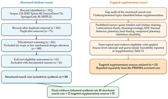
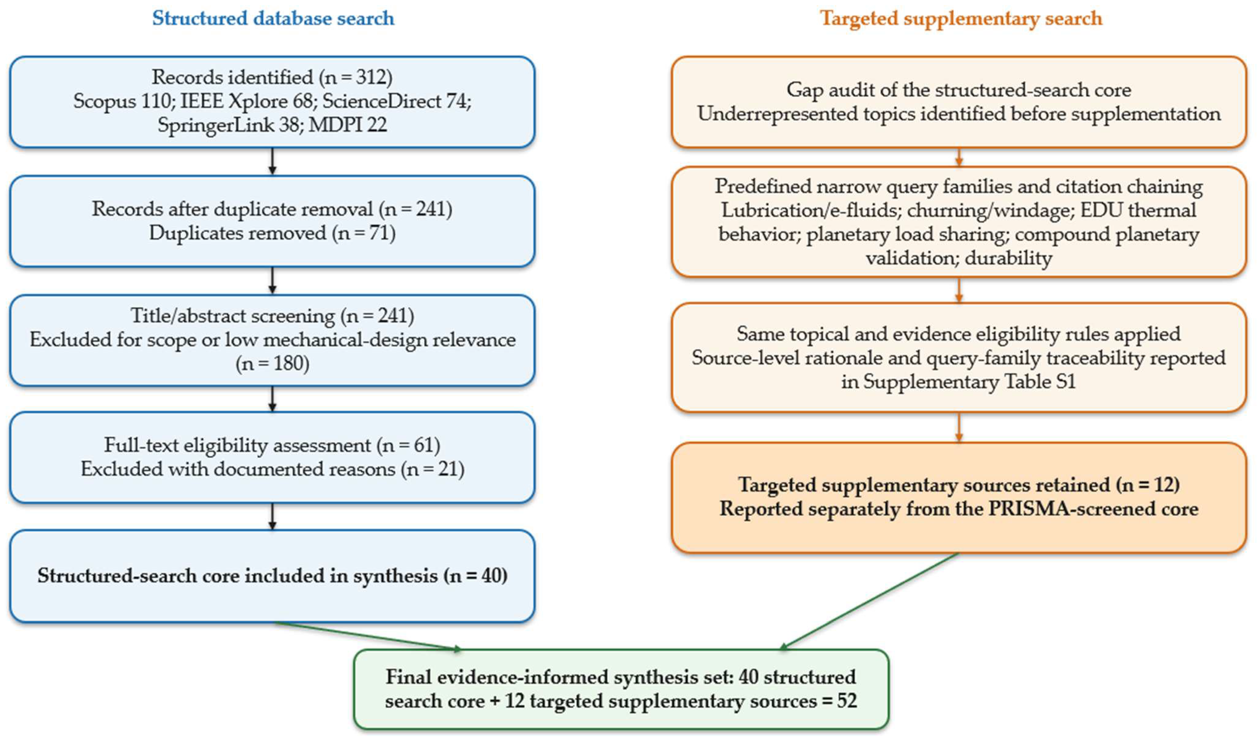
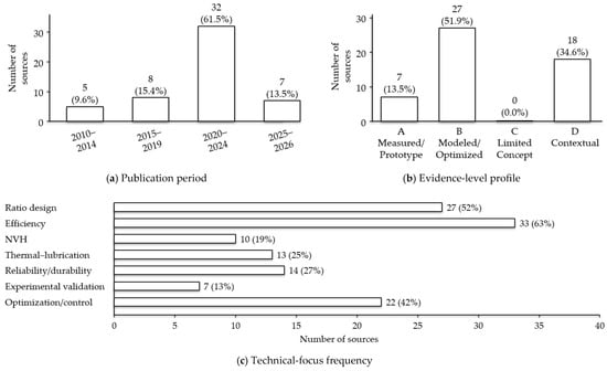
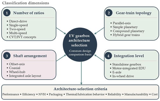
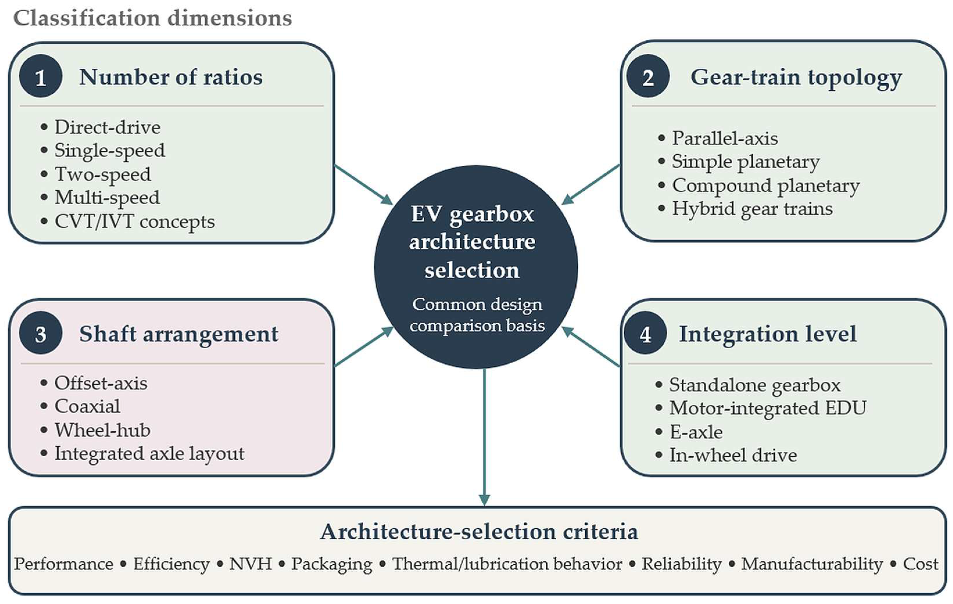
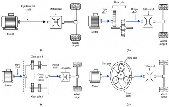
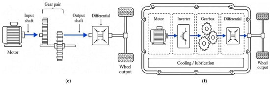
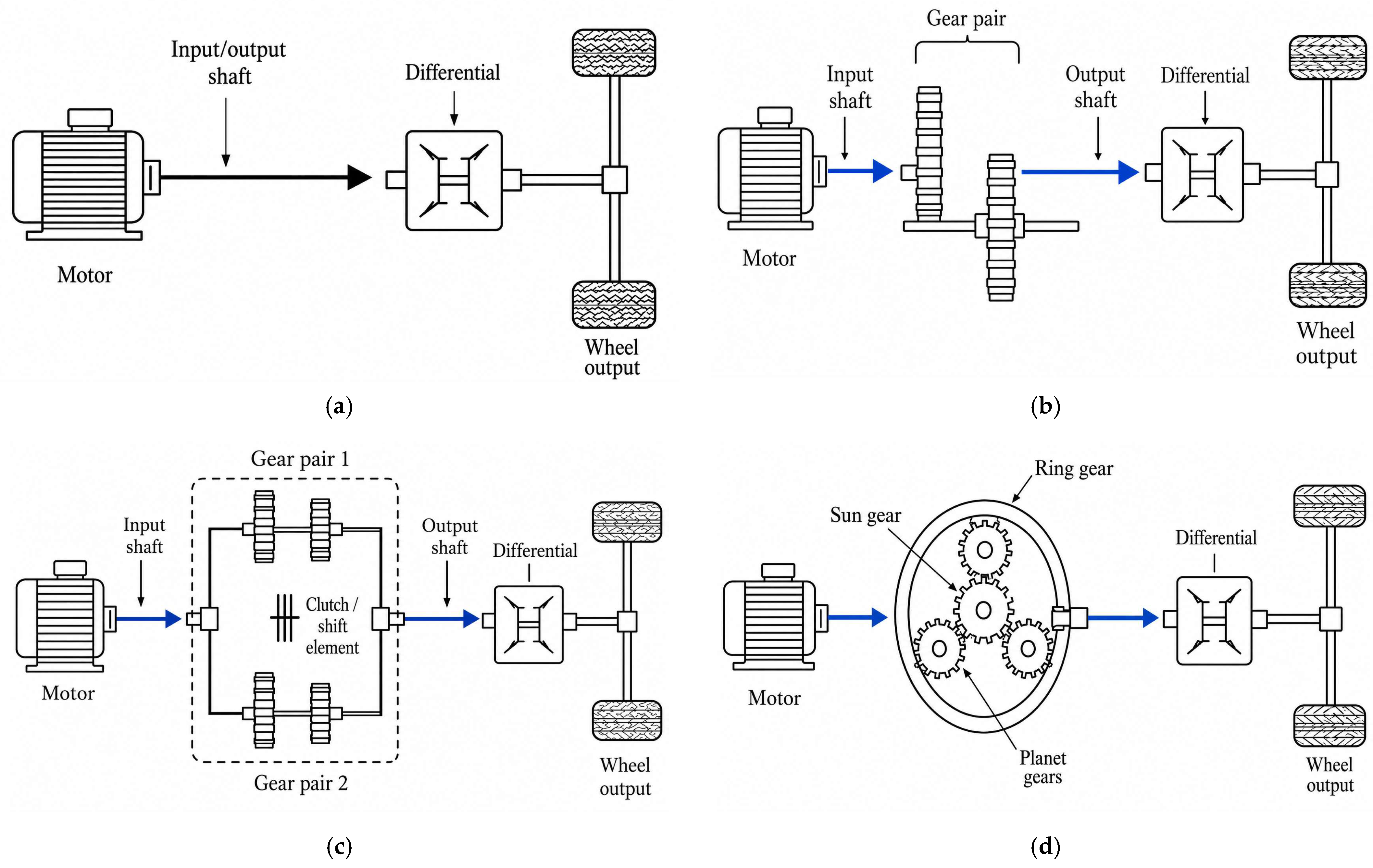
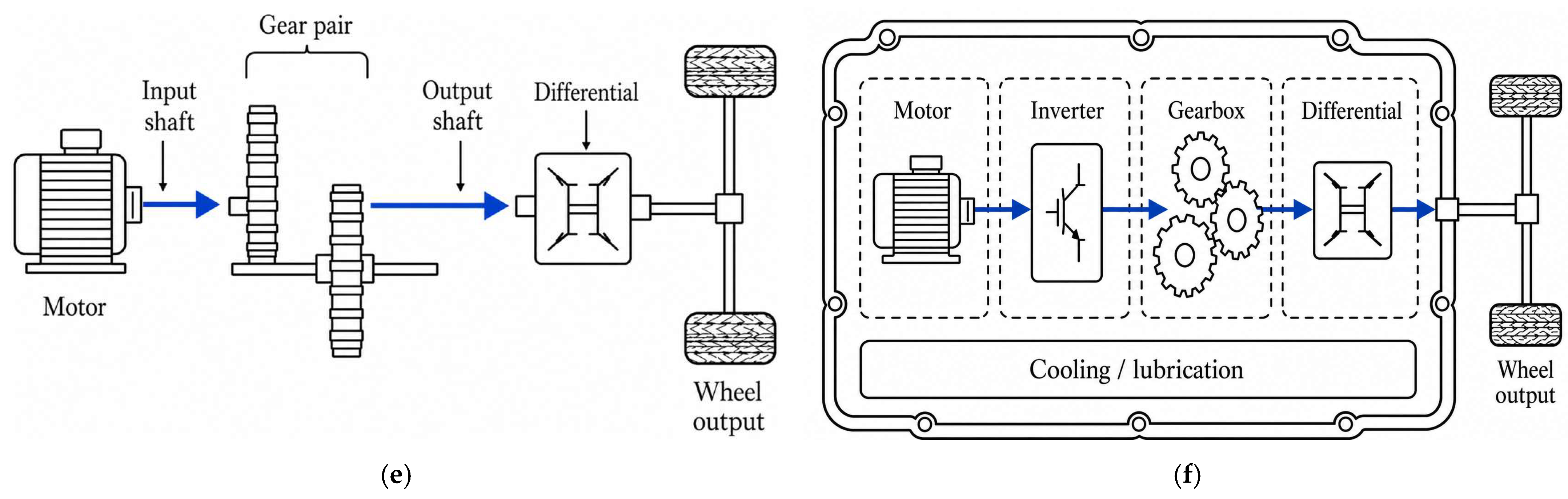
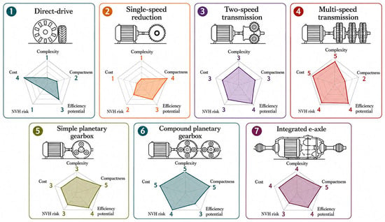
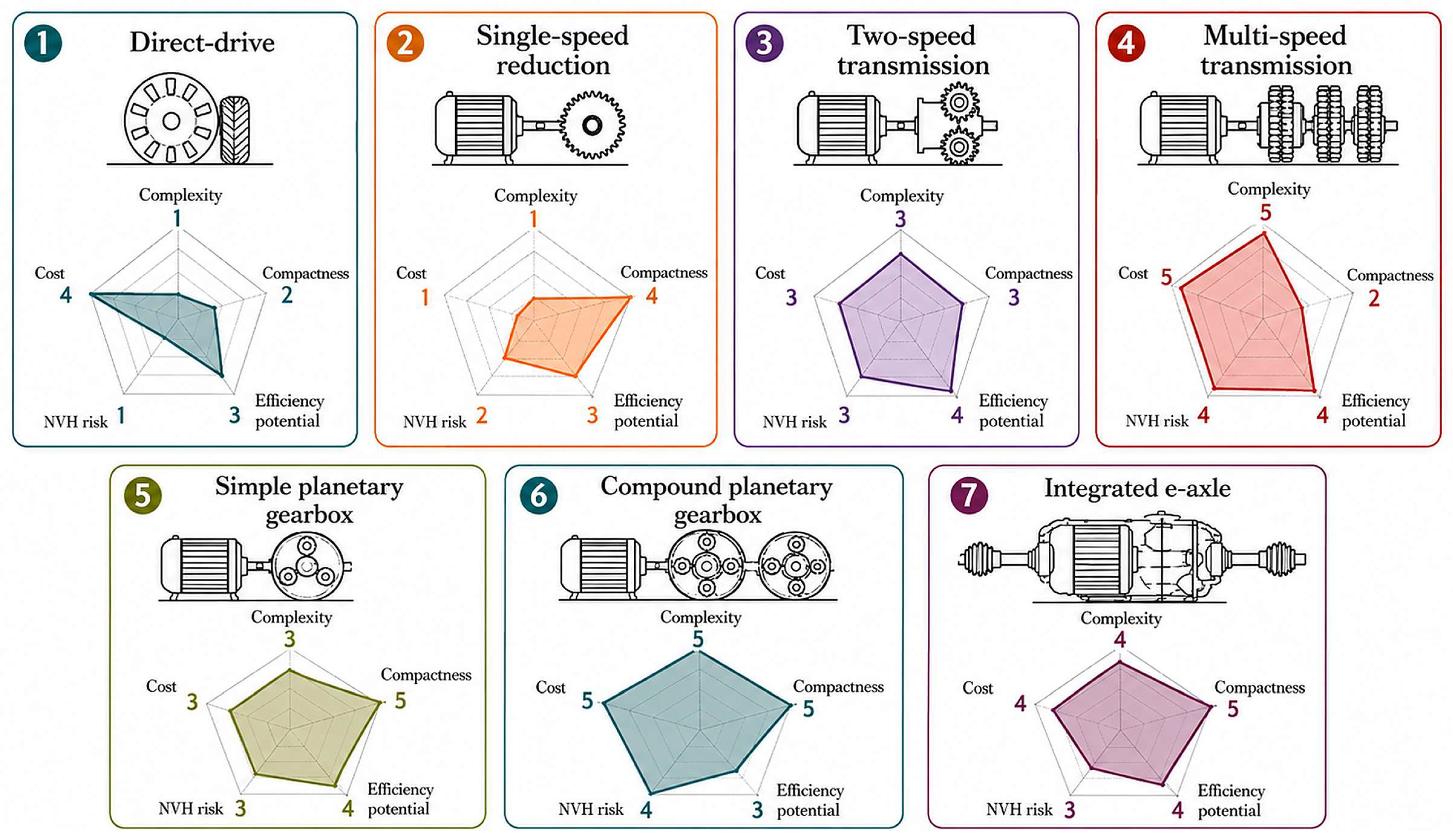
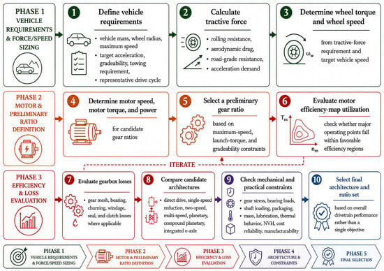
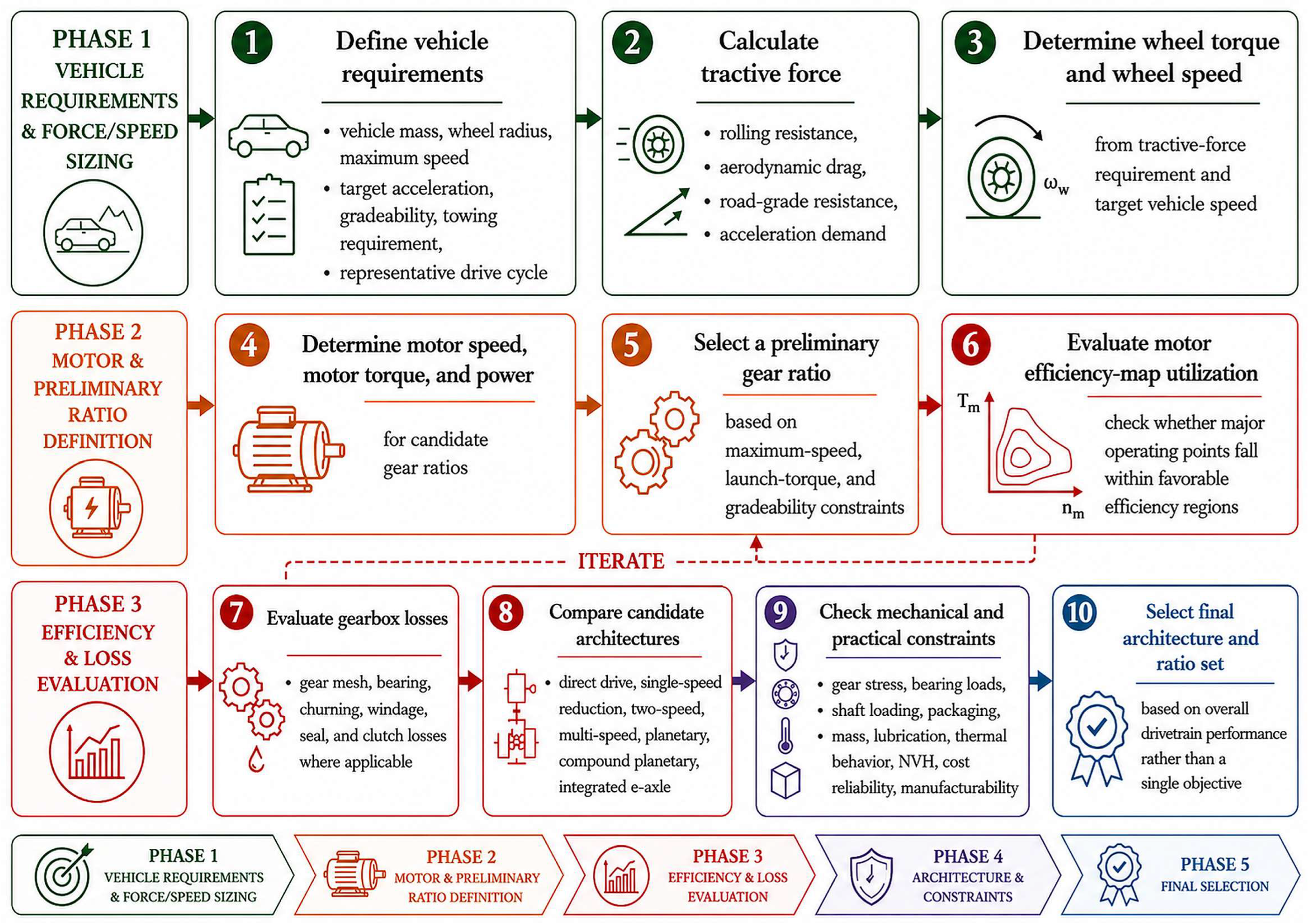
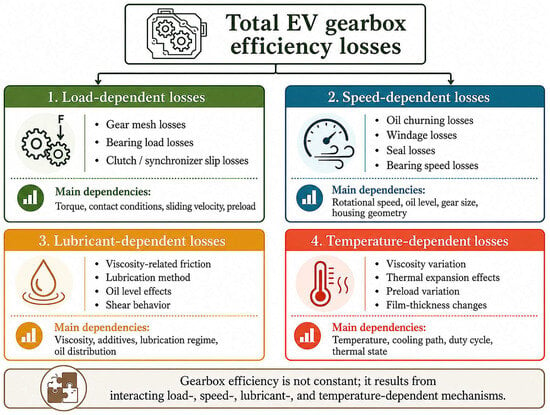
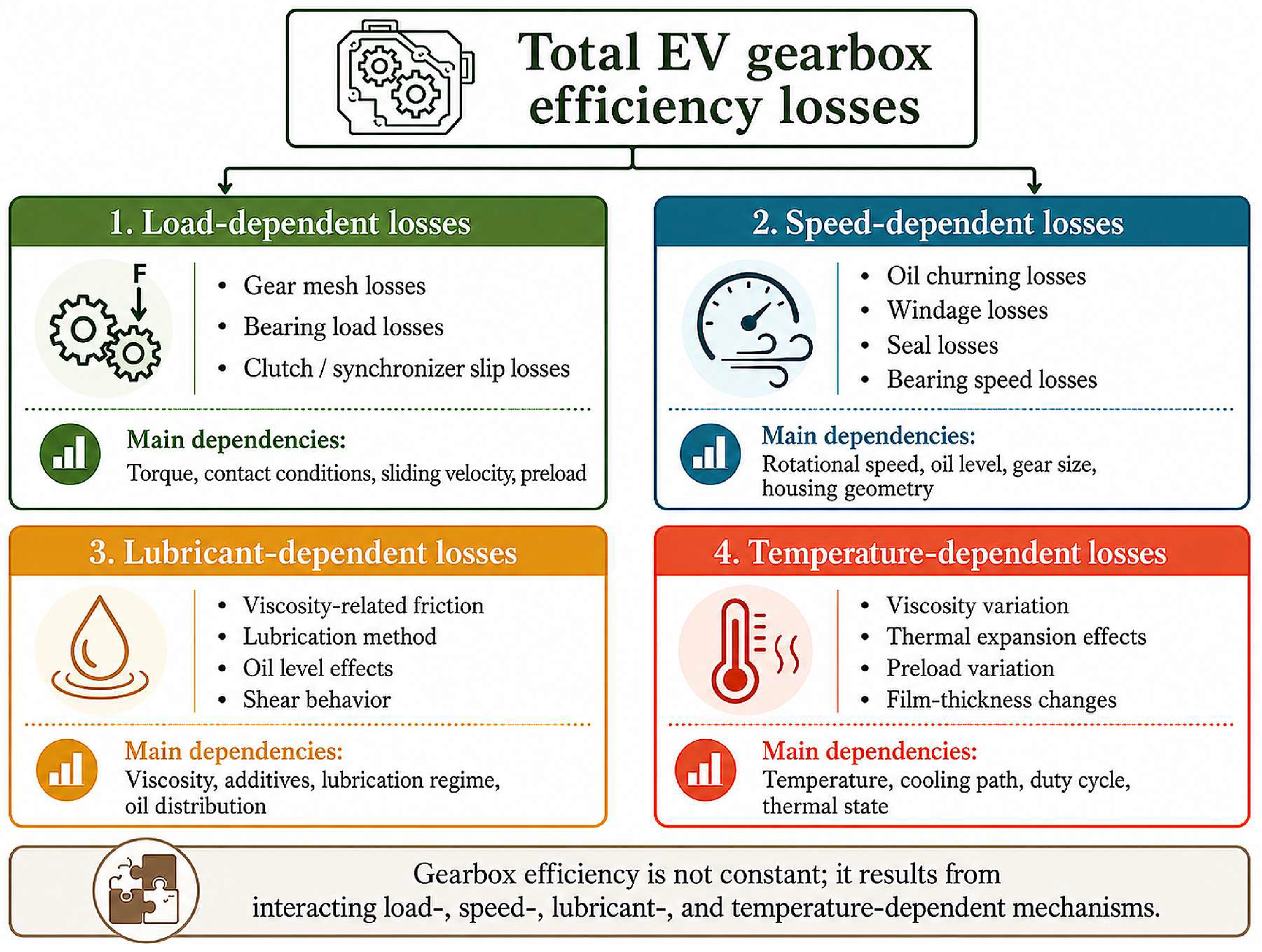
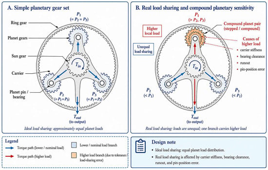
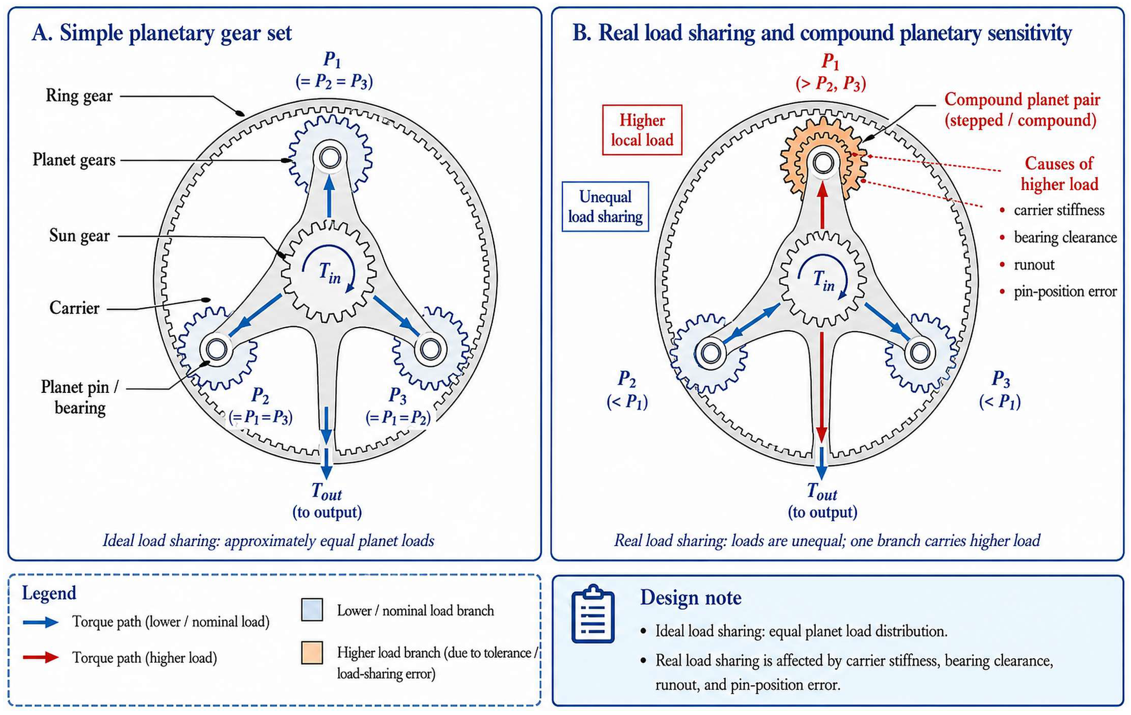
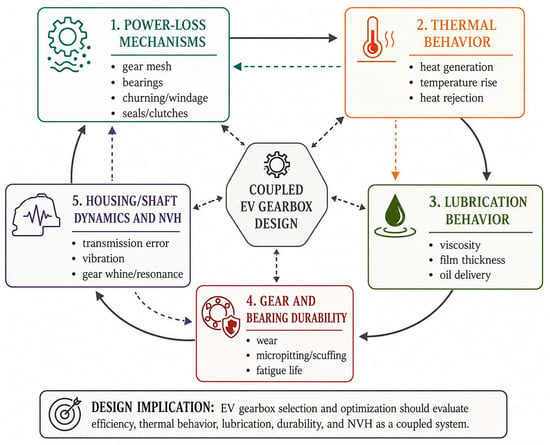
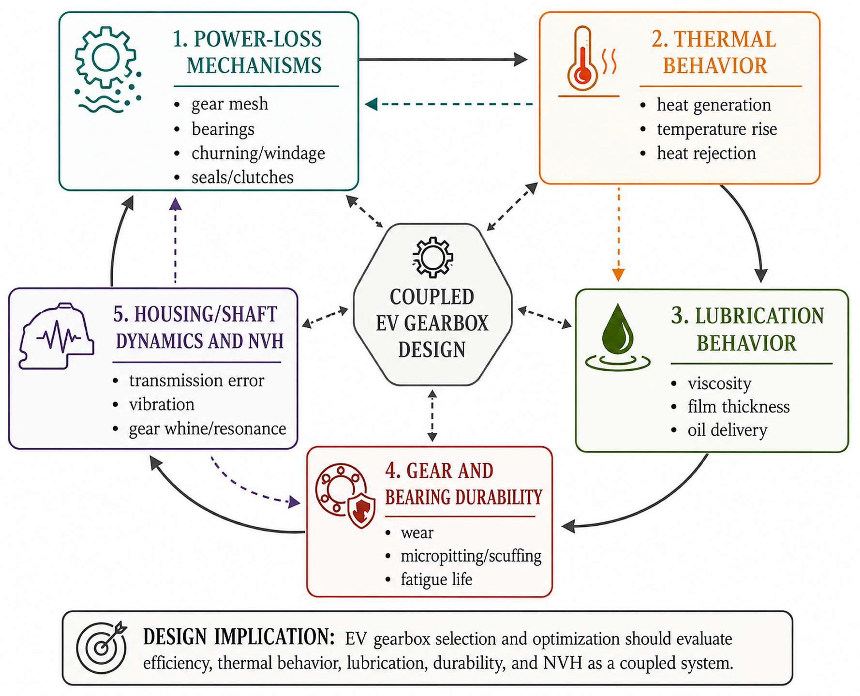
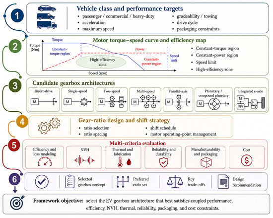
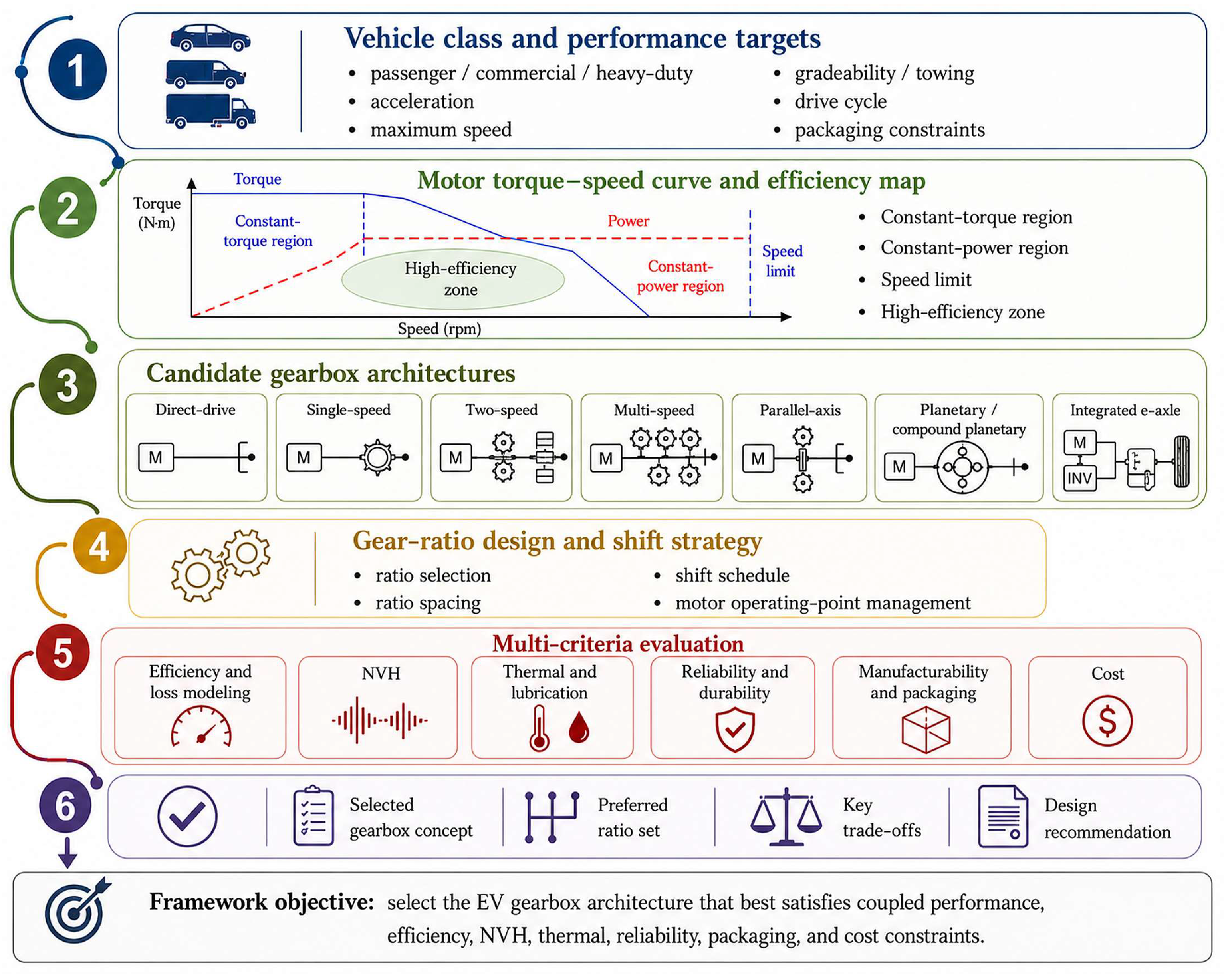
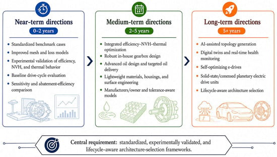
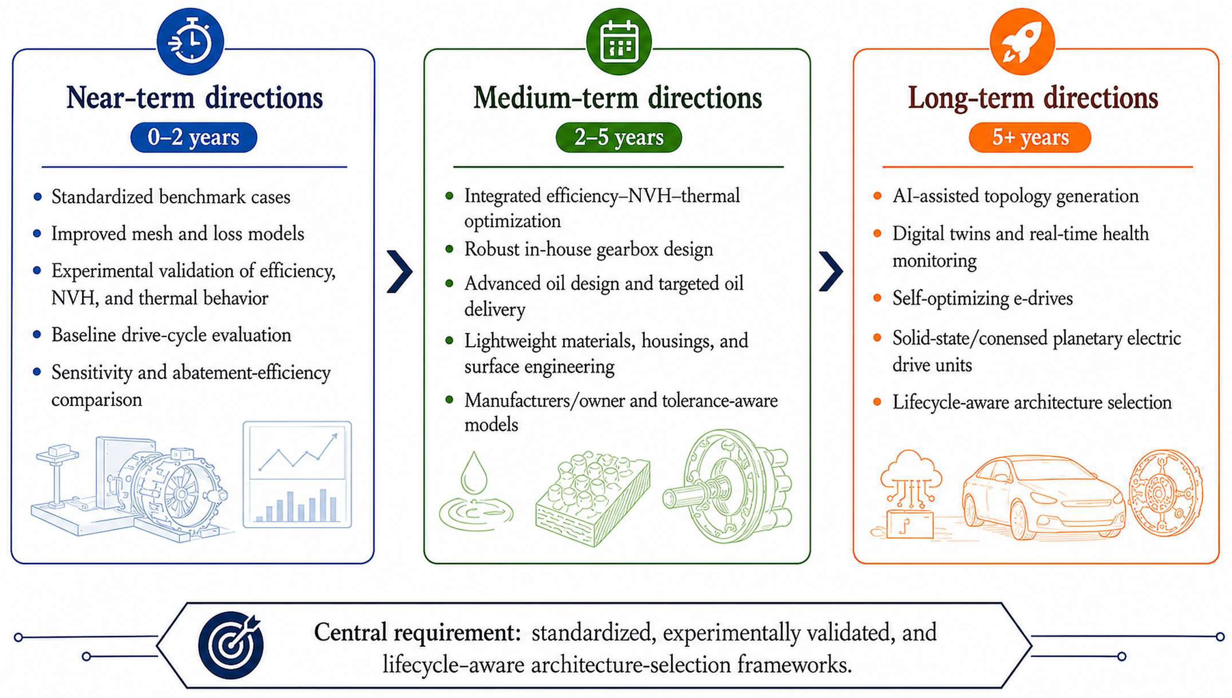

Disclaimer/Publisher’s Note: The statements, opinions and data contained in all publications are solely those of the individual author(s) and contributor(s) and not of MDPI and/or the editor(s). MDPI and/or the editor(s) disclaim responsibility for any injury to people or property resulting from any ideas, methods, instructions or products referred to in the content. |
© 2026 by the authors. Licensee MDPI, Basel, Switzerland. This article is an open access article distributed under the terms and conditions of the Creative Commons Attribution (CC BY) license.