


Abstract
Rockets were launched from a freely ascending balloon, and the attitude dynamics of the rockoon system were investigated. Compared with ground-based or aircraft-based launches, rockoons offer reduced aerodynamic drag and pressure losses, leading to higher maximum altitudes of sub-orbital trajectory and improved launch capacity to earth orbits. To ensure trajectory accuracy and flight safety, an azimuth control system based on a control moment gyroscope (CMG) was implemented. The launcher, suspended beneath a helium balloon, was equipped with a CMG device for active azimuth control. Three model rocket launches were conducted, and attitude data were obtained using multiple accelerometers installed on the rocket and launcher. The results confirmed that azimuth control remained effective during free ascent, with the azimuth error at ignition within 7° of the target in all three launches. Oscillatory motion was observed in roll and yaw angles. It was identified as rotation about the launcher’s principal inertia axis, indicating no significant impact on the rocket’s flight trajectory. Additionally, pitch-up behavior during launch due to rail friction was observed, consistent with previous studies. Frequency analysis showed that a double-pendulum model reproduced the measured first-mode frequency within approximately 2%, while the measured second-mode frequencies were higher than the predictions, indicating an increase in the effective pendulum length due to the relaxed constraint of the balloon suspension. Under free-flight conditions, the first mode was no longer observed within the measurable frequency band, consistent with the removal of the ground constraint. These findings provide an experimental characterization of the attitude dynamics of rockoon launches with active azimuth control.
1. Introduction
A rockoon, which stands for a rocket launched from a balloon, is a promising method for launching small rockets at a low cost. In conventional ground-based launches, the atmosphere imposes significant disadvantages. By launching rockets from the upper stratosphere, it is possible to improve launch capacity and apogee altitudes significantly. At an altitude of approximately 20 km, the atmospheric density is about 7% of that at sea level, substantially reducing aerodynamic losses. Additionally, the lower ambient pressure allows the rocket engine to have a larger nozzle expansion ratio, thereby mitigating atmospheric pressure losses and improving specific impulse. Furthermore, launching from a higher altitude allows for a smaller initial elevation angle of the trajectory, resulting in reduced gravity losses and improved overall efficiency [1,2].
Another type of air-launch rocket involves those launched from aircraft, with notable examples including Pegasus and Virgin Orbit. This method shares some benefits with the rockoon system. However, the launch altitude is below 12 km [3], which is lower than that achievable with high-altitude balloons. The primary advantages of air launches stem from the low atmospheric density and pressure at the launch altitudes; the rockoon provides superior conditions. Although rockoons are generally unable to carry rockets as large as those deployed from aircraft, they do not require costly fixed assets or maintenance expenses associated with aircraft, making them more suitable for launching small-scale rockets.
The first rockoon experiment was performed by a group led by Van Allen in the 1950s with the aim of conducting sub-orbital scientific missions to study the upper atmosphere. Since then, some rockoon systems have been developed [4,5,6,7,8], but those launchers lacked a mechanism for controlling the azimuth angle during release. In Japan, the HIMES project [9] carried out an atmospheric re-entry experiment in which a rocket was launched from a balloon whose azimuth was actively controlled by a reaction control system (RCS); however, the rocket was ignited in free fall immediately after release. Because the attitude of a falling rocket at ignition is difficult to predict with sufficient accuracy, the adoption of a rail-type launcher is preferable.
Thus, an azimuth control system is required for a launcher suspended from a balloon to ensure orbital insertion accuracy and flight safety of the rockoon system. Obayashi Corporation, Minato, Japan, a major construction company, developed a device called SkyJuster, which enables control of the azimuthal orientation of suspended loads [10]. In construction projects of the Tokyo Skytree, suspended loads tend to rotate due to wind, often resulting in work being suspended during strong winds. The SkyJuster employs a control moment gyroscope (CMG) mechanism equipped with a high-speed rotating disk, enabling it to stabilize a 28-ton load even under high-wind conditions.
In a previous study [11], the authors developed a rockoon launch system incorporating a CMG device for azimuth control. This system features a pair of rotating disks mounted on a gimbal, allowing for precise azimuthal control. In this demonstration, a crane was used instead of a balloon to conduct a model rocket launch from the CMG-controlled launcher. The experiment validated the effectiveness of azimuth control; however, it also revealed issues related to oscillations in the elevation angle during launch. The launcher’s behavior was analyzed using a double-pendulum model. Nevertheless, in the case of a crane-based set-up, the system behaves as a pendulum with a fixed upper point and thus does not replicate the conditions of an actual rockoon launch. Similarly, tethered balloon systems—where the balloon is anchored to the ground—also exhibit constraints analogous to those in crane-based experiments.
Studies closely related to the constituent dynamics of such a system have been reported. The pendulation and torsional dynamics of gondolas suspended beneath freely ascending high-altitude balloons have been measured and modeled [12,13], including recent work on balloons carrying cable-suspended loads [14]. The swing dynamics and control of loads suspended from cranes and rotorcraft have been studied extensively [15,16], and a gyroscopic rotation control device for crane-suspended loads has been demonstrated [17]. Regarding instrumentation, attitude reconstruction from low-cost gyroscopes on sounding rockets, together with bias calibration and drift compensation techniques, has been established [18,19]. However, no experimental data have been reported on the attitude behavior of an azimuth-controlled launcher suspended beneath a freely ascending balloon during an actual rocket launch.
As a continuation of the previous study [11], a new experiment was conducted in which a balloon was temporarily released from its tether, allowing it to ascend freely. A rocket was then launched from an attitude-controlled platform suspended from the ascending balloon. This set-up enabled investigation of the influence of attitude variations—free from ground constraints—on the rocket’s trajectory during a rockoon launch.
The novelty and specific contributions of the present work, relative to the previous crane-based experiment [11], are threefold. First, to the best of the authors’ knowledge, this is the first reported rocket launch from a CMG-based, azimuth-controlled launcher suspended beneath a freely ascending balloon, in which the launcher attitude was measured throughout the release, free-ascent, ignition, and rail departure phases. Second, the free ascent realizes the unconstrained suspension condition that neither a crane nor a tethered balloon can reproduce; the difference in the constraint condition appears directly in the modal structure of the pendulum motion, and this difference is quantified here for the first time. Third, the double-pendulum model proposed in the previous study is extended to, and examined under, the free-ascent condition, providing a basis for predicting the attitude disturbance at ignition in future rockoon systems.
2. Dynamics of Suspended Launcher
This section briefly reviews the theory of azimuthal and elevational motion of the launcher suspended by balloon, described in the previous study [11].
2.1. Azimuth Control with CMG
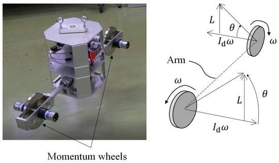
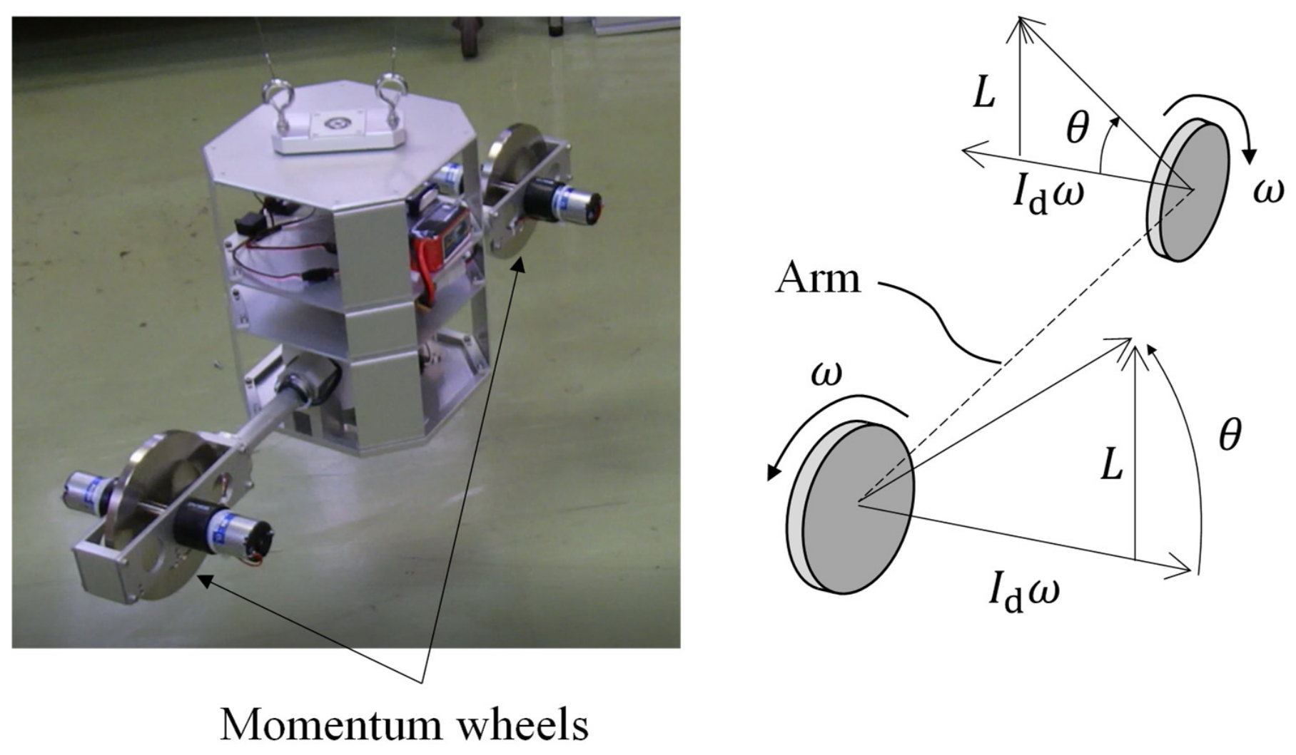
Figure 1 shows the azimuth control device used in this study, which utilizes a pair of momentum wheels, each mounted on opposite ends of a horizontal arm and driven at the same angular velocity by electric motors. The rotational axes of the wheels are tilted by an angle with respect to the arm. This configuration functions as a CMG, enabling torque generation about the vertical axis. When the wheels are initially aligned horizontally and spinning at angular velocity , the angular momentum of each wheel is , where is the moment of inertia of the rotor. Upon tilting the axes by an angle , the vertical component of angular momentum for each wheel becomes . Since the wheels rotate in opposite directions, the vertical momentum components add constructively, producing a net vertical angular momentum change of . By conservation of angular momentum, this results in the launcher acquiring an equal and opposite angular momentum, inducing rotation around the vertical axis at the angular velocity:
where is the moment of inertia of the launcher. Thus, the launcher rotates clockwise (when viewed from above) in response to the gyroscopic tilting. Differentiating the angular momentum equation with respect to time yields:
Figure 1.
A picture of the azimuth angle control device and an illustration of its dynamics.
This relationship indicates that azimuthal torque is maximized at lower tilting angles and vanishes at = 90°, known as CMG saturation. At this point, further rotation of the launcher is not possible unless the wheel speed itself is changed.
2.2. Pendulum Motion
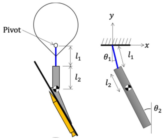
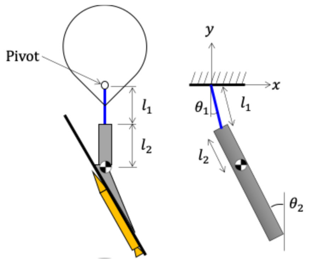
The system described in this study does not actively control the elevation angle. The launch rail is fixed to the azimuth controller, while elevation naturally oscillates around an equilibrium point. After the rocket is launched, the center of gravity of the system shifts, leading to pendulum-like motion about the equilibrium orientation. This dynamic behavior of the launcher, including post-launch oscillations, is represented by double pendulum model shown in Figure 2. A rigid rod was suspended using a weightless wire with a rigid support, which is a pivot of the pendulum motion. The mass, center of gravity, and moment of inertia of the rod were the same as those of the launcher assembly. The wire connecting the launcher and hook has length . The eigenfrequencies of this model are obtained by solving Euler–Lagrange equations for the attitude angles.
Figure 2.
Double-pendulum model.
There are two solutions for .
The solutions are the 1st and 2nd-mode frequencies (. The mode shape parameter is obtained as follows.
where and denote the angular amplitudes of the suspension wire and of the rigid rod, respectively, oscillating at the eigenfrequency in each mode. The amplitude ratio in Equation (5) therefore characterizes the mode shape associated with each of the two eigenfrequencies and .
3. Experimental Method
3.1. Rockoon System
3.1.1. Balloon
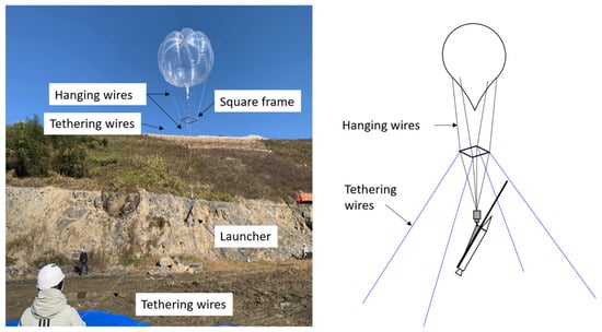
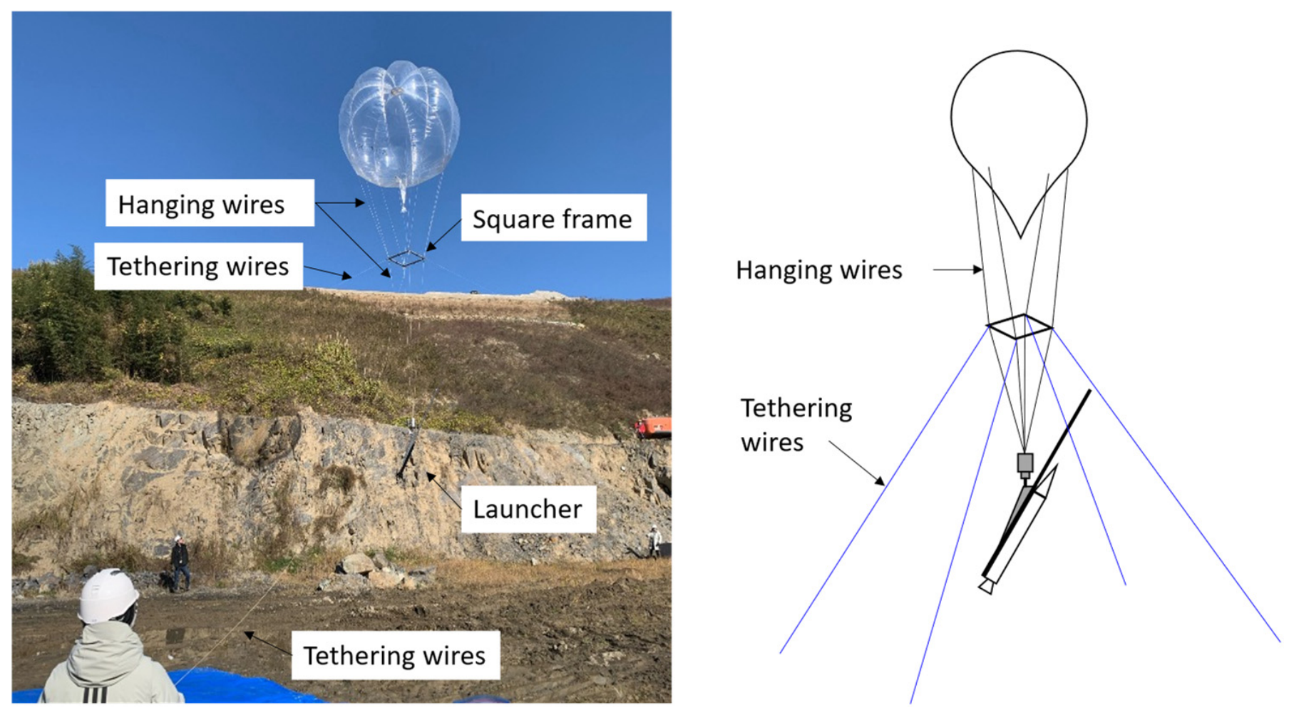
A 4.5 m diameter plastic balloon filled with helium gas was prepared, below which the launcher was suspended. As shown in Figure 3, a square rigid frame was located just below the balloon, and four hanging wires attached from the corners of the frame were connected to the attitude control device. The upper connection of the attitude control device had a swivel, allowing it to rotate freely in the azimuth direction relative to the balloon. When the balloon was tethered before launch, four tethering wires were hung from the corners of the square frame to secure it to the ground. As described below, when launching the rocket, the tethering wires were released, and the rocket was launched during the approximately 7 s untethered free ascent.
Figure 3.
A photograph of the rockoon system tethered before the launch.
3.1.2. Attitude Controller
The attitude control device used in this experiment is shown in Figure 1, and is the same as that used in the previous report [11]. It is equipped with a pair of rotating disks, and the rotation axis of each disk can be tilted. The left and right disks rotate in opposite directions, and their angular momentum vectors point in opposite directions. By tilting the rotation axes so that both of these vectors point upward, a change in angular momentum occurs, and a rotational torque around the vertical axis is generated in the entire attitude control device. It is manually controlled by a radio control. The main parameters of the rockoon system, including the mass properties of the launcher assembly used in the pendulum analysis in Section 5.3, are summarized in Table 1.
Table 1.
Main parameters of rockoon system.
3.1.3. Rocket
The rocket used was a Spitfire PML 30385 manufactured by LOC Precision, WI, USA (diameter: 76 mm, height: 1288 mm, and mass: 1.16 kg). It was equipped with an G69N-P engine by AeroTech, UT, USA, which has an average thrust of 80 N. It had three fixed tail fins, and the engine’s thrust direction was fixed. Three rocket bodies were prepared and launched.
3.1.4. Measurement System
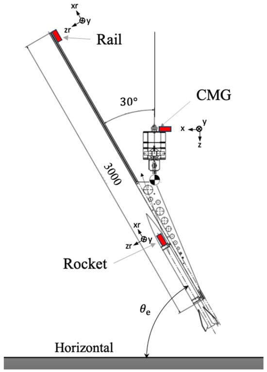
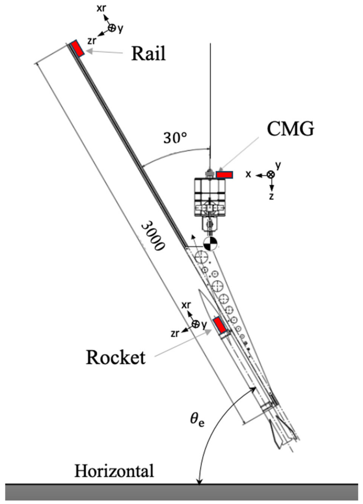
Six-axis accelerometers AMWS020 (manufactured by ATR-Promotions) were installed in three locations: inside the rocket, at the tip of the launcher rail, and at the top of the attitude control system (Figure 4). These sensors measure three-axis translational acceleration and angular velocity. The sensor module is 37 mm × 46 mm × 12 mm in size and weighs approximately 22 g; the measurement ranges of the accelerometer and the gyroscope are selectable up to ±16 g and ±2000 deg/s, respectively. In this experiment, the accelerometer range was set to ±4 g (approximately ±40 m/s2) and the gyroscope range to ±500 deg/s. The angular velocity is integrated over time to calculate the attitude angle.
Figure 4.
The location of the accelerometers and their orientation. The sensors on the rail and in the rocket are inclined by the rail elevation angle θe with respect to the horizontal, defining the xryzr coordinate system.
A bias correction term was added to remove the drift caused by the sensor offset. The value of was determined so that the integrated attitude angle showed no net drift over the one min interval prior to launch. This procedure corresponds to the standard bias-compensation approach for attitude reconstruction from rate-gyro integration [18,19]. The estimated bias ranged from 0.01 to 0.5 deg/s depending on the axis and the sensor. Since b is determined such that the net drift vanishes over the 60 s window, the residual bias is bounded by the ratio of the pendulum oscillation amplitude (a few degrees) to the window length, i.e., below approximately 0.05 deg/s; the resulting attitude angle error accumulated over the 30 s analysis interval of each launch is therefore smaller than approximately 1.5°.
The accelerometers at the tip of the rail and the rocket are installed at the elevation angle along coordinate system, as shown in Figure 4. The measured angular velocities around and axes were converted to the same coordinate system as the CMG accelerometer by rotating them around the y axis by the angle .
These angular velocities were integrated as Equation (6) to obtain the attitude angles.
The sampling rate was set to 10 Hz in the first launch test; however, it was found that the rate was insufficient to evaluate the detailed attitude behavior. Thus, it was changed to 100 Hz in the following tests. The system is battery-powered, and data can be stored in internal storage. Since it lacked telemetry, the accelerometers were recovered after launch and the data were retrieved.
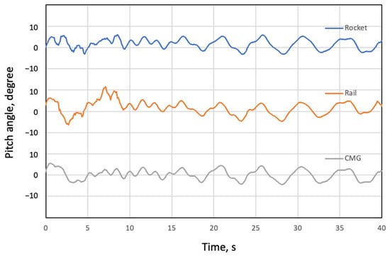
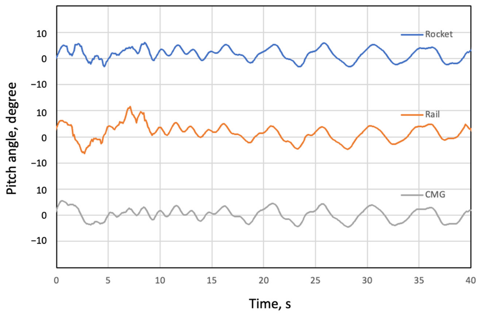
Each of the three sensors has a different clock and requires precise synchronization. It was performed in data processing after the test. The time axis was synchronized using the pendulum motion before launch and the spike position when the rocket leaves the launcher. Figure 5 shows the pitch angle history obtained by the three sensors during the first launch. Since the pendulum motion of the launcher before release is consistent, we confirmed that the angular velocity of each part was accurately obtained. The residual synchronization error with this procedure is estimated to be within one sampling interval (0.01 s at 100 Hz), which is sufficiently small compared with the pendulum periods of interest (1.5 s or longer).
Figure 5.
Pitch angle history obtained by the three sensors during the first launch.
3.2. Launch Operation
The launch was carried out in the following procedure. First, with the balloon still tethered, the attitude control system was manually operated to point the launcher at the target azimuth, which was set to a magnetic azimuth of 265° for the first launch and 180° for the second and third launches. After confirming safety in the air, the four tethering wires were released simultaneously. The released balloon and launcher start to ascend. Approximately three seconds after the release, the engine ignition device was activated remotely and the rocket was launched. During this time, the attitude control system continued to be operated to direct the launcher azimuth to the target. After launch, the tethering wires were caught to stop the balloon’s ascent. This free ascending time was limited to approximately seven seconds due to restrictions on the length of the tethering wires.
3.3. Safety and Regulatory Measures
The experiments were conducted at a quarry site operated by Ube Kyouritsu Sangyou, Inc., in Yamaguchi, Japan, the same site as in the previous study [11], under the following safety measures. The tethering wires limited the maximum altitude of the balloon to below 150 m above the ground and prevented the system from drifting away, even in the case of an ignition failure. The apogee of the rocket also remained below 150 m above the ground. Since the entire experiment was thus conducted below an altitude of 150 m, no permission from or notification to the aviation authority was required under the Japanese regulations. During the operation, the launch area was closed to non-participants, and all personnel were kept at a safe distance from the launcher. The rocket was ignited remotely, only after visual confirmation that the airspace above the site and the surrounding ground area were clear. Regarding the wind conditions, the operational criteria required holding the operation at a ground wind speed of 5 m/s or higher and postponing it at 8 m/s or higher; the launches were conducted under favorable conditions with a ground wind speed below 3 m/s.
4. Results
Three launch tests were conducted. Supplementary Video S1 shows the launch behavior of the third launch. Table 2 lists the engine burn time and accelerometer sampling rates for each launch. Parts of the data in the second and third launches were lost due to the malfunction of the accelerometer. The sampling rate of 10 Hz in the first launch was found to be insufficient to resolve the detailed attitude behavior, and it was increased to 100 Hz for the subsequent launches; accordingly, the quantitative analyses in Section 5 are based on the 100 Hz data of the second and third launches, while the first launch is used only for the qualitative confirmation of the overall behavior. Although parts of the data were lost, the sensor on the launcher rail operated at 100 Hz in both the second and third launches, and the structural rigidity of the launcher, which is confirmed later in this section, ensures that the launcher attitude can be evaluated from the remaining sensors. It should nevertheless be noted that the conclusions of this study are drawn from a small number of launches, each with a free-ascent duration of only approximately 7 s, and their generality should be examined in future experiments with longer free-flight durations.
Table 2.
Summary of launch experiments.
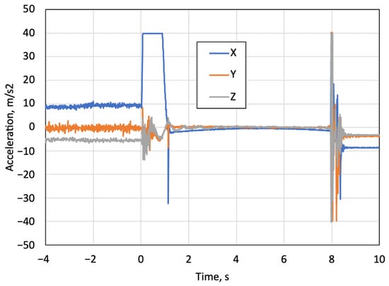
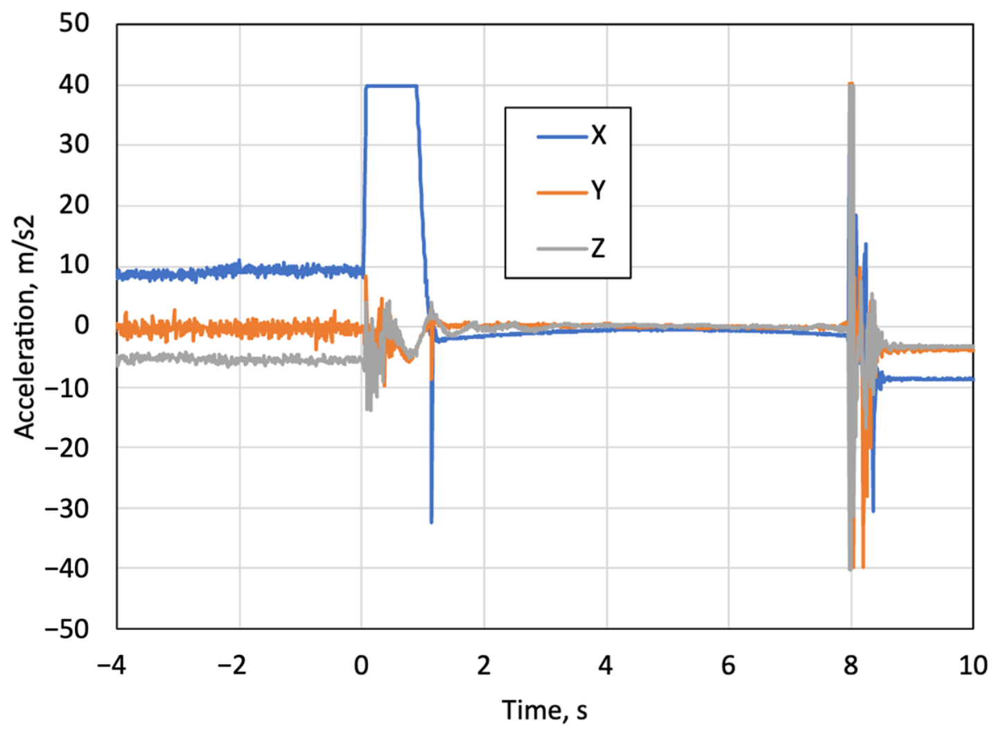
Figure 6 shows the time history of rocket acceleration data acquired during the second launch. Prior to launch, the gravitational acceleration is decomposed into the X- and Z-axis components due to the elevation angle of the launcher. The time t = 0 s is defined as the time of rocket ignition. The upper limit of the sensors was set to 40 m/s2, prioritizing higher temporal resolution. Although the acceleration of the rocket exceeds this limit value during the engine burning, it has less importance in the following analyses. Following the ignition, the measured acceleration remained constant at the upper limit during the engine burn, as the actual acceleration exceeded the measurement range. The rocket subsequently landed at t = 7.9 s. It should be emphasized that the attitude angles in this study are reconstructed solely from the angular velocity measurements of the gyroscopes; the saturation of the translational accelerometers during the burn therefore does not affect the reconstructed attitude angles or the subsequent interpretation.
Figure 6.
Accelerations of the rocket obtained in the second launch.
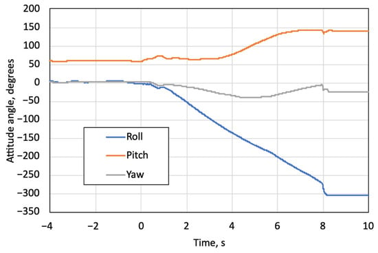
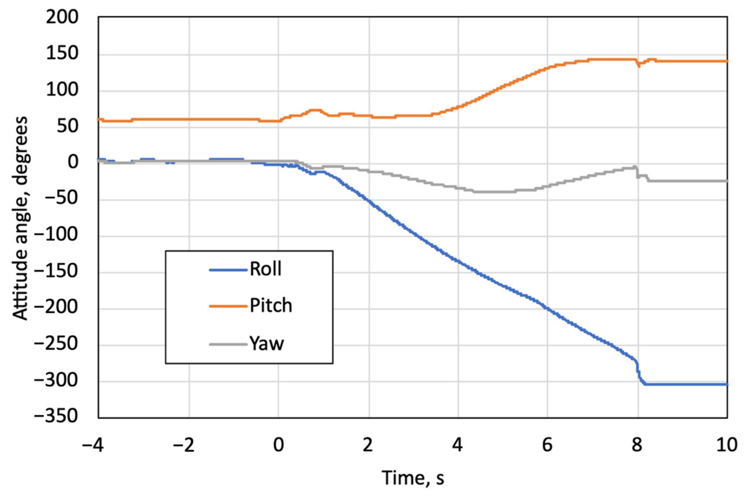
Figure 7 presents the attitude angle data of the rocket obtained during the second launch. After leaving the launcher rail, the rocket flew while spinning at a nearly constant roll rate and landed at t = 8.0 s without significant deviation.
Figure 7.
Attitude angles of the rocket obtained in the second launch.
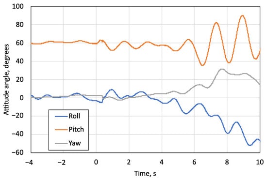
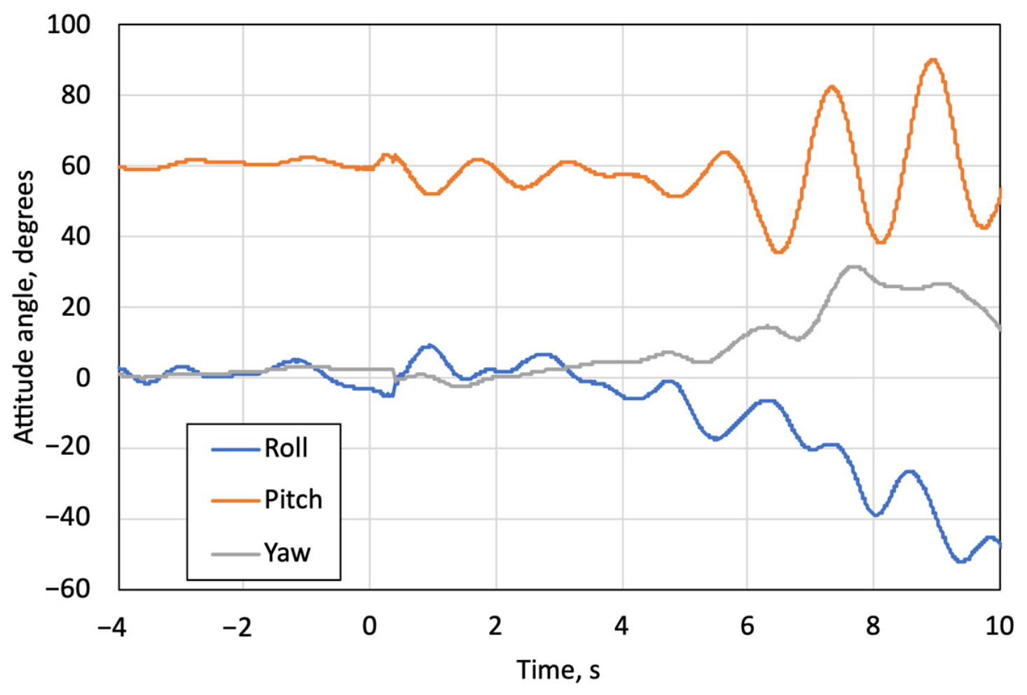
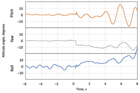
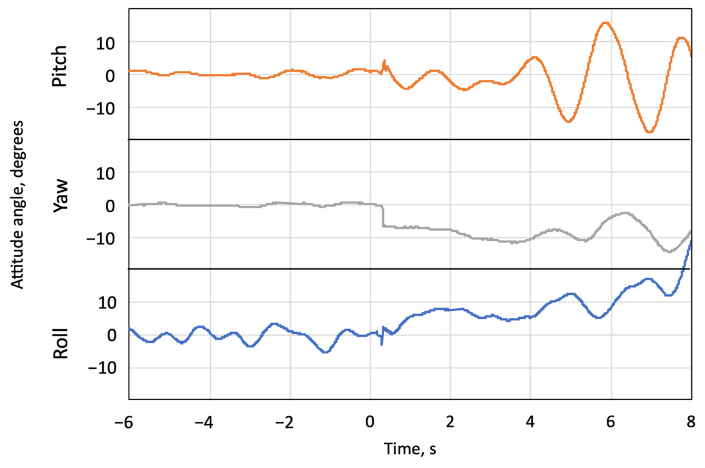
Figure 8 shows the attitude angle data of the launcher rail obtained during the second launch. During the rail-sliding phase after the ignition, a pitch-up phenomenon induced by the friction force was observed. Similar behavior was also observed in previous crane-based tests. When the rocket cleared the rail tip at t = 0.4 s after ignition, a transient disturbance in the attitude was observed, after which the launcher experienced double-pendulum motion. An additional attitude disturbance was observed at approximately t = 7 s, when the tethering wire arrested the balloon’s ascent.
Figure 8.
Attitude angles in coordinate system of launcher rail obtained in second launch.
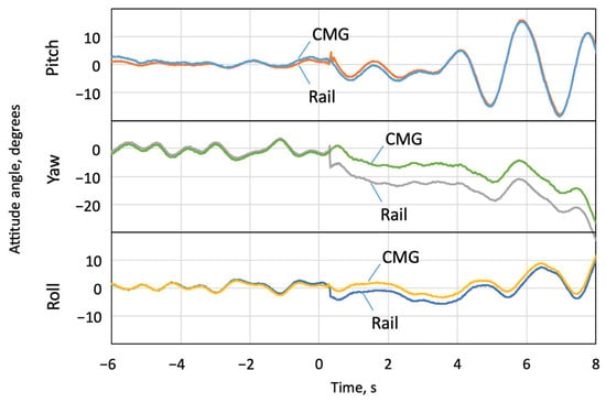
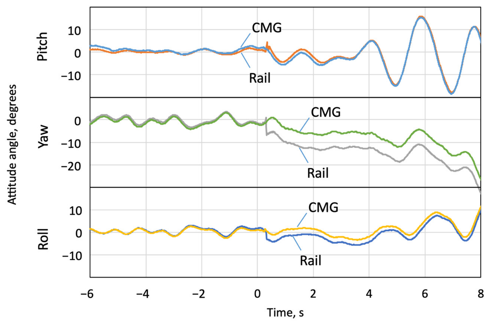
The pre-launch azimuth angle remained within an error of 7°. To quantify the azimuth control performance, Table 3 summarizes, for each launch, the azimuth error with respect to the target azimuth, evaluated at the release of the tethering wires, at ignition, and at the rail departure, together with the maximum and root-mean-square (RMS) errors over the interval from the release to the rail departure. The metrics are evaluated up to the rail departure because the azimuth of the launcher no longer affects the rocket trajectory afterwards, and because the integration error grows in the post-departure yaw record, as discussed below. The azimuth error at ignition was within 7° in all three launches. The roll angle and yaw angle exhibited synchronized oscillatory variations; the time of each peak coincides in yaw and roll angles, whereas no coupling with the pitch angle was observed. Figure 9 shows the attitude angles of the launcher rail acquired during the third launch, transformed via the coordinate conversion given in Equation (7), alongside the attitude angles measured with the sensor on CMG. The close agreement between each two lines indicates that structural deformation of the launcher frame was negligible. Discontinuities observed in attitude data on the rail at t = 0.4 s are due to the integral error caused by the sudden release of load at the rocket clearance, and are not physical phenomena. This integral error appears as a nearly constant offset between the rail and CMG records after the clearance, which is largest in the yaw axis (approximately 7°). Since the two records remain parallel to each other after the clearance, the angular rates measured by the two sensors continue to agree; therefore, the conclusion that the structural deformation of the launcher frame was negligible is not affected by this offset. This is also supported by the post-test inspection of the launcher, in which no permanent deformation corresponding to such an offset was found. The coupling between the roll angle and azimuth angle observed during the second launch was reproduced with consistency in the third launch as well.
Table 3.
A summary of the key results of the three launches. Azimuth errors are defined with respect to the target azimuth (a magnetic azimuth of 265° for N1 and 180° for N2 and N3); the maximum and RMS errors are evaluated over the interval from the release of the tethering wires (approximately 3 s before ignition) to the rail departure. For N2, the azimuth was obtained from the rail sensor transformed by Equation (7) because the CMG sensor data were lost; the N1 values are based on the 10 Hz data. * The pitch-up angle of N1 was not evaluated, because the 10 Hz sampling rate is insufficient to resolve the 0.4 s rail-sliding phase.
Figure 9.
Attitude angles in coordinate system of launcher in third launch obtained with sensor on rail and CMG.
5. Discussion
5.1. Coupling Between Roll and Yaw Angle
In Figure 8 and Figure 9, the synchronous motion in yaw and roll angles was observed. If the yaw angle, that is, the azimuth angle, was to fluctuate, this would lead to deviation in the rocket’s flight direction. However, the following discussion reveals that this is a rotational oscillation about the rail axis and does not affect the flight trajectory. The attitude angle obtained at the rail tip in the coordinate system is shown in Figure 10. There is fluctuation in the (roll) axis, but none in the (yaw) axis, indicating a rotational oscillation around the rail (roll) axis. The reason for the rotation around the rail axis is that the launcher’s principal axes of inertia are oriented in the direction, and the moment of inertia on the axis is the smallest. As is known in the theory of dynamics, the free rotation of a rigid body tends to occur about its two principal axes of inertia, which correspond to the maximum and minimum moments of inertia.
Figure 10.
The attitude angles in the coordinate system of the launcher in the third launch obtained with the sensor on the rail.
5.2. Pitch-Up Phenomenon After Ignition
As shown in Figure 8, when the launcher begins sliding on the rail after ignition, a pitch-up phenomenon occurs due to the friction between the rocket and the rail. This phenomenon, which was also observed in the previous crane experiment, was reproduced and confirmed in this free balloon experiment. The frictional force is the product of the coefficient of friction and the normal force, which is significantly caused by thrust misalignment [11]. A pitch-up of 3.2 degrees is observed in the second launch as shown in Figure 8, and approximately 1 degree in the third launch as shown in Figure 9. This study utilizes the same launcher and rocket as previously used, and the range expected from a thrust misalignment variation of is to . Therefore, it is expected the engine used for the second launch had a thrust misalignment of approximately , which is a plausible manufacturing error.
5.3. Double-Pendulum Behaviors
To validate the pendulum motion model of the launcher, Fast Fourier Transform (FFT) analysis was performed on the attitude history. The analysis was conducted for the elevation angle about the pitch axis and the attitude angle about the rail axis, because the rotational motion in the direction perpendicular to the y-axis is dominated by the oscillatory rotation about the rail axis, as described above.
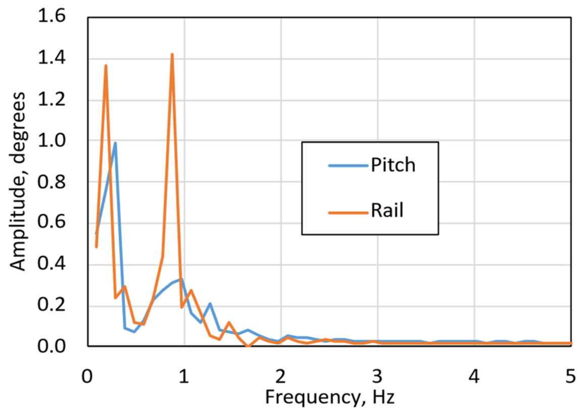
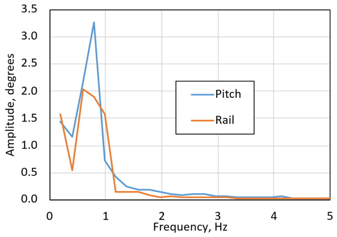
Figure 11 presents the analysis results for the 10 s period prior to rocket launch, during which the system was held stationary by a tethering wire. Two distinct peaks are clearly observed for both the pitch and rail axes, confirming that the system can be represented by a double pendulum model. Figure 12 presents the analysis results for the 5 s period following the rocket launch, during which the balloon was ascending freely. The first mode near 0.2 Hz is absent in this case. Due to the time constraint imposed by the free-ascent period between balloon launch and the subsequent re-engagement of the tethering wire, the measurement duration was limited to 5 s; consequently, only frequency components above 0.2 Hz were obtained owing to the inherent characteristics of the FFT. Therefore, the present data indicate only that the first mode was not observed at or above 0.2 Hz; whether the mode vanished or shifted to a frequency below 0.2 Hz cannot be distinguished conclusively within the 5 s window. This behavior is consistent with the absence of a fixed constraint point during free balloon ascent, in which case the first mode is expected to change to the pendulum mode of the entire system, comprising both the balloon and the launcher. Confirming this interpretation requires a longer free-flight duration, as discussed in Section 6.
Figure 11.
Frequency components of the attitude angles about the pitch and rail axes obtained from 14 to 4 s before the second launch, during which the balloon is tethered.
Figure 12.
Frequency components of the attitude angles about the pitch and rail axes obtained from 0.5 to 5.5 s after the second launch, during which the balloon was in free flight.
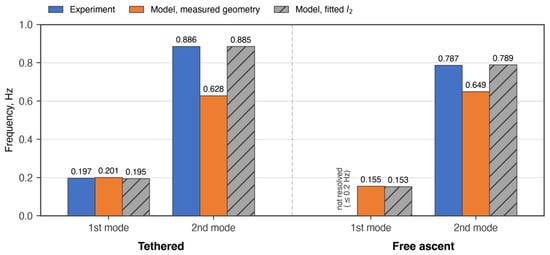
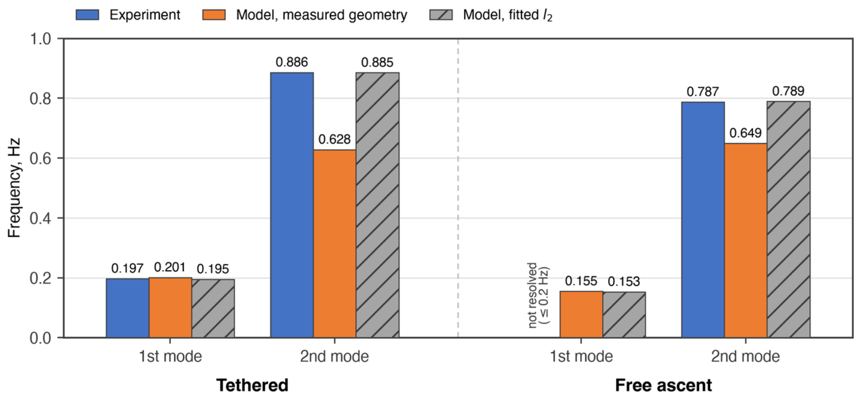
To make the validation of the double-pendulum model quantitative, the eigenfrequencies calculated from Equation (4) are compared with the measured peak frequencies in Figure 13. The mass and the moment of inertia of the launcher assembly are those listed in Table 1. The pendulum length l1 was taken as the distance from the effective pivot to the suspension point of the launcher: 5.6 m under the tethered condition and 10 m, corresponding to the balloon, under the free ascent. The length l2 is the distance from the suspension point to the center of gravity of the launcher assembly (0.483 m before the launch and 0.378 m after the rocket departure). With these measured parameters, the model reproduces the first-mode frequency within approximately 2%, whereas it underpredicts the second-mode frequency by approximately 29% under the tethered condition and 18% under the free ascent. The second mode is reproduced within approximately 1% when the effective length l2 is treated as a fitting parameter: 0.90 m (1.9 times the measured value) under the tethered condition and 0.55 m (1.5 times) under the free ascent. Since the mass properties of the launcher are unchanged from the previous crane-based study [11], in which the measured geometry reproduced the frequencies without such an adjustment, the increase in the effective l2 is attributed to the relaxation of the constraint condition at the attachment points of the four hanging wires when the launcher is suspended from the balloon instead of a crane hook.
Figure 13.
Comparison of the measured and calculated eigenfrequencies of the pendulum motion (second launch). The fitted values of l2 are 0.90 m for the tethered condition and 0.55 m for the free ascent. The first-mode frequency under the free ascent could not be resolved (≤0.2 Hz).
6. Conclusions
The azimuth control system remained functional in the balloon launch configuration in all three launches, maintaining the pre-launch azimuth angle within 7° of the target, consistent with its behavior observed during crane-based testing. Within the range of the conditions tested, the double-pendulum model reproduced the measured first-mode frequency within approximately 2%, and the second-mode frequency was reproduced by treating the effective suspension length as a fitting parameter, reflecting the relaxed constraint of the balloon suspension (Figure 13). The pitch-up behavior upon launcher release was observed as predicted. The launcher undergoes oscillatory rotation about its principal axis of inertia. By aligning the rail axis parallel to the principal axis of inertia, the influence of this rotational oscillation on the azimuth angle can be effectively suppressed. In contrast to a tethered balloon, the first mode was no longer observed within the measurable frequency band (≥0.2 Hz) during free ascent. This behavior was observed consistently along both the pitch and rail axes, and is attributed to the relaxation of the constraint conditions at the pendulum fulcrum. It should be emphasized that these conclusions are drawn from three launches with a free-ascent duration of approximately 7 s each and with partial loss of the sensor data; accordingly, any implications for flight safety, trajectory accuracy, and the feasibility of operational rockoon launches are limited to what was directly demonstrated under these conditions. Further investigation is required to fully characterize the behavior of the first mode during free flight; in particular, balloon experiments of longer duration will be necessary to resolve low-frequency components that could not be captured within the current measurement window.
Supplementary Materials
The following supporting information can be downloaded at: https://www.mdpi.com/article/10.3390/aerospace13080709/s1, Video S1: Launch behavior of the rockoon system during the third launch.
Author Contributions
Conceptualization, T.S. and Y.W.; methodology, Y.W. and T.S.; Investigation, T.S.; formal analysis, T.S.; data curation, T.S.; writing—original draft preparation, T.S.; writing—review and editing, Y.W.; supervision, Y.W. and S.O.; project administration, Y.W. and S.O.; funding acquisition, S.O. All authors have read and agreed to the published version of the manuscript.
Funding
This research was supported by the Innovation Creation Platform Program (“Fukushima Tech Create”) of the Fukushima Innovation Coast Framework Promotion Organization, Fukushima, Japan, under the project “Demonstration experiment of air-launching a micro rocket using a plastic balloon” (notification number 4-Fuku-I-333).
Data Availability Statement
The data presented in this study are available on request from the corresponding author due to commercial restrictions. The data can be shared subject to a non-disclosure agreement.
Acknowledgments
We would like to thank the students at the Space Transportation Engineering Laboratory at Chiba Institute of Technology, who supported the preparation and operation of the air-launch experiments at Yamaguchi.
Conflicts of Interest
Authors T.S. and Y.W. are affiliated with AstroX Inc., which is developing rockoon launch services. The remaining authors declare that the research was conducted in the absence of any commercial or financial relationships that could be construed as a potential conflict of interest.
Abbreviations
The following abbreviations are used in this manuscript:
| CMG | Control moment gyroscope |
| RCS | Reaction control system |
| FFT | Fast Fourier Transform |
References
- Shoyama, T.; Wada, Y.; Matsui, T. Conceptual study on low-melting-point thermoplastic Fuel/Nitrous oxide hybrid rockoon. J. Spacecr. Rocket. 2022, 59, 286–294. [Google Scholar] [CrossRef] [Scilit]
- Okninski, A.; Raurell, D.S.; Mitre, A.R. Feasibility of a low-cost sounding rockoon platform. Acta Astronaut. 2016, 127, 335–344. [Google Scholar] [CrossRef] [Scilit]
- Vaughn, M.; Kwong, J.; Pomerantz, W. LauncherOne: Virgin orbit’s dedicated launch vehicle for small satellites & impact to the space enterprise vision. In Proceedings of the Advanced Maui Optical and Space Surveillance Technologies Conference (AMOS), Marriott, HI, USA, 19–22 September 2017; pp. 19–22. [Google Scholar]
- Itokawa, H. The Japanese Sounding Rockets. J. Jet Propuls. 1957, 27, 286–288. [Google Scholar] [CrossRef] [Scilit]
- JP Aerospace Rockoons. Available online: http://www.jpaerospace.com/rockoons.html (accessed on 8 April 2026).
- Dougherty, K. Upper atmospheric research at Woomera: The Australian-built sounding rockets. Acta Astronaut. 2006, 59, 54–67. [Google Scholar] [CrossRef] [Scilit]
- Johnson, I.; Roberson, R.; Truitt, C.; Waldock, J.; Northway, P.; Pfaff, M.; Winglee, R. Development of a Rockoon Launch Platform and a Sulfur Fuel Pulsed Plasma Thruster CubeSAT. In Proceedings of the AIAA/USU Conference on Small Satellites, Logan, UT, USA, 4–7 August 2014; p. SSC14-P2-10. [Google Scholar]
- Gómez, B.U.; Illescas, A.N.; Moreno, D.P.; Reina, A.R.; Raurell, D.S. LEEM Rockoon project: Developing a high altitude platform. In Proceedings of the International Astronautical Congress, IAC, Jerusalem, Israel, 12–16 October 2015; No. 29662. pp. 8922–8930. [Google Scholar]
- Inatani, Y.; Akiba, R.; Hinada, M.; Nagatomo, M. Atmospheric reentry flight test of winged space vehicle. In Proceedings of the AlAA 4th International Aerospace Planes Conference, Orlando, FL, USA, 1–4 December 1992. [Google Scholar]
- SkyJuster® for Suspended Platforms: Uses Gyroscopic Effect to Reduce Swaying of Suspended Platforms. Available online: https://www.obayashi.co.jp/chronicle/130th/en/archives/chapter4_1_2.html (accessed on 8 April 2026).
- Shoyama, T.; Banno, A.; Furuta, Y.; Kurata, N.; Ode, D.; Wada, Y.; Matsui, T. Air-Launch Experiment Using Suspended Rail Launcher for Rockoon. Aerospace 2021, 8, 289. [Google Scholar] [CrossRef] [Scilit]
- Gemignani, M.; Marcuccio, S. Dynamic Characterization of a High-Altitude Balloon during a Flight Campaign for the Detection of ISM Radio Background in the Stratosphere. Aerospace 2021, 8, 21. [Google Scholar] [CrossRef] [Scilit]
- Kassarian, E.; Sanfedino, F.; Alazard, D.; Evain, H.; Montel, J. Modeling and Stability of Balloon-Borne Gondolas with Coupled Pendulum-Torsion Dynamics. Aerosp. Sci. Technol. 2021, 112, 106607. [Google Scholar] [CrossRef] [Scilit]
- Chen, L.; Song, Z.; Lin, J. Dynamics and Control of a High-Altitude Balloon with Slung Load. Aeronaut. J. 2024, 128, 2856–2878. [Google Scholar] [CrossRef] [Scilit]
- Abdel-Rahman, E.M.; Nayfeh, A.H.; Masoud, Z.N. Dynamics and Control of Cranes: A Review. J. Vib. Control 2003, 9, 863–908. [Google Scholar] [CrossRef] [Scilit]
- Cicolani, L.S.; Kanning, G.; Synnestvedt, R. Simulation of the Dynamics of Helicopter Slung Load Systems. J. Am. Helicopter Soc. 1995, 40, 44–61. [Google Scholar] [CrossRef] [Scilit]
- Wada, M.; Mori, Y.; Tagawa, Y. Development of a Suspended-Load Rotation-Control Device for Cranes with Gyroscopic Damper and Control by Wind Force (Concept, Modeling and Experiments). Mech. Eng. J. 2020, 7, 20–00268. [Google Scholar] [CrossRef] [Scilit]
- Bekkeng, J.K.; Psiaki, M.L. Attitude Estimation for Sounding Rockets Using Microelectromechanical System Gyros. J. Guid. Control Dyn. 2008, 31, 533–542. [Google Scholar] [CrossRef] [Scilit]
- Mansoor, S.; Bhatti, U.I.; Bhatti, A.I.; Ali, S.M.D. Improved Attitude Determination by Compensation of Gyroscopic Drift by Use of Accelerometers and Magnetometers. Measurement 2019, 131, 582–589. [Google Scholar] [CrossRef] [Scilit]

Disclaimer/Publisher’s Note: The statements, opinions and data contained in all publications are solely those of the individual author(s) and contributor(s) and not of MDPI and/or the editor(s). MDPI and/or the editor(s) disclaim responsibility for any injury to people or property resulting from any ideas, methods, instructions or products referred to in the content. |
© 2026 by the authors. Licensee MDPI, Basel, Switzerland. This article is an open access article distributed under the terms and conditions of the Creative Commons Attribution (CC BY) license.