


Abstract
Unmanned Air Vehicles (UAVs) are becoming increasingly popular and widely used in a variety of industries such as agriculture, construction, delivery, surveillance, rescue operations, mapping, wildlife tracking and many more. With the advancements in technology, UAVs are becoming more autonomous and able to perform tasks with minimal human intervention, rendering their use indispensable for military and law enforcement purposes. In terms of control surfaces, V-tail configurations are commonly used on UAVs due to their advantages in control and stability performance, as well as their ability to reduce drag and improve overall efficiency. However, research on V-tail design and sizing is limited, particularly for Class I mini-UAVs. The objective of this paper is to identify a methodology for the Conceptual and Preliminary sizing and design of a V-tail of a Class I Mini UAV (NATO classification). The methodology follows the design of a V-tail from the characteristics of the conventional tail of the UAV. Once the characteristics of the conventional tail are extracted, V-tail geometric characteristics are computed. The stability derivatives of the V-tail are then calculated. The methodology for the analytical aerodynamic characteristics and stability derivatives is a combination of two existing methodologies: one methodology for V-tail stability and control derivatives, which refers to the Preliminary or Detailed Design of an aircraft, and one methodology for a conventional tail design, which refers to the Conceptual and Preliminary design of an aircraft. With this combination, a V-tail Preliminary design methodology was achieved. Furthermore, the aerodynamic characteristics and stability derivatives of the designed V-tail were verified by Low Fidelity Aerodynamics simulation, and then by High Fidelity Aerodynamics by means of Computational Fluid Dynamics (CFD).
1. Introduction
Unmanned Aerial Vehicles (UAVs) have experienced significant growth during the last few decades due to their increasing use in military, surveillance, environmental monitoring, mapping, precision agriculture, logistics, and infrastructure inspection applications. Consequently, considerable research effort has been devoted to the design, optimization, and performance assessment of fixed-wing UAV configurations. Several methodologies for UAV conceptual and preliminary design have been proposed in the literature, covering aerodynamic design, performance analysis, multidisciplinary optimization, and propulsion integration [1,2,3,4,5].
During the conceptual and preliminary design phases, semi-empirical and low-order aerodynamic methodologies are commonly employed because detailed aircraft geometries and validated high-fidelity numerical models are not generally available. These methodologies typically combine simplified aerodynamic theory, empirical correction factors, statistical relationships, and information obtained from previously developed aircraft. Their relatively low computational cost allows a large number of candidate configurations to be assessed before more demanding CFD simulations, wind-tunnel tests, or flight-test campaigns are conducted. In the context of V-tail UAVs, Babu et al. [6] presented the preliminary design and aerodynamic analysis of a surveillance UAV, while Lesalli [7] combined preliminary aircraft sizing with static-stability analysis performed using XFLR5. These studies demonstrate the practical value of semi-empirical and low-fidelity approaches during early aircraft development, although they mainly assess predefined V-tail geometries rather than directly estimating the V-tail geometry and its associated stability derivatives.
Among the various empennage configurations employed in fixed-wing aircraft, the V-tail configuration represents an attractive unconventional solution that combines the functions of the horizontal and vertical stabilizers into two inclined surfaces. By reducing the number of aerodynamic surfaces and their intersections, V-tail configurations can potentially reduce structural weight and parasite drag while improving packaging efficiency and accommodating pusher-propeller arrangements. Furthermore, the absence of a conventional vertical stabilizer may reduce interference effects and improve the overall aerodynamic efficiency of the aircraft. However, these benefits are accompanied by increased aerodynamic coupling between longitudinal and lateral–directional motions, more complex control allocation requirements, and sensitivity to geometric parameters such as dihedral angle, aspect ratio, and control-surface effectiveness [3,4,5,6,7,8,9,10,11,12,13].
The aerodynamic behavior and stability characteristics of V-tail configurations have been studied for several decades. Early investigations conducted by Purser and Campbell [8], Polhamus and Moss [9], and Schade [10] established the theoretical and experimental foundations of V-tail aerodynamics and stability analysis. Their work provided analytical expressions and wind-tunnel data for evaluating the aerodynamic forces, moments, and control effectiveness associated with V-tail aircraft. More recent studies have further investigated the influence of tail geometry on static stability and control characteristics. Phillips et al. [11] examined the effects of tail dihedral on aircraft static stability, while Abzug [12] investigated V-tail stall behavior under combined angles of attack and sideslip. García-Hernández et al. [13] developed dynamic and failure models for a V-tail remotely piloted aircraft system, highlighting the importance of accurately predicting the coupling between longitudinal and lateral–directional dynamics.
The influence of the V-tail inclination angle has also been examined for low-speed and manned-aircraft configurations. Zhang et al. [14] investigated the effects of tail dihedral on the aerodynamic characteristics of a low-speed aircraft and showed that variations in the tail inclination affect both the longitudinal and lateral-directional aerodynamic response. Musa et al. [15] compared the sensitivity of different aircraft tail arrangements to yaw disturbances, whereas Musa et al. [16] specifically examined the influence of tail dihedral angle on lateral-directional stability under sideslip conditions. These investigations indicate that the V-tail dihedral angle cannot be selected solely through geometric equivalence with conventional horizontal and vertical stabilizers, because it directly influences the distribution of aerodynamic forces and moments between the longitudinal and lateral-directional axes.
Unconventional empennage arrangements have additionally been studied in the context of larger manned and transport aircraft. Sánchez-Carmona et al. [17] examined unconventional tail configurations for transport-aircraft applications, considering aerodynamic efficiency, stability, control, and aircraft-integration requirements. Such approaches demonstrate that the V-tail concept is not limited to small UAVs and that it may also provide aerodynamic, structural, and integration advantages for larger aircraft. Nevertheless, methodologies developed for manned transport aircraft cannot necessarily be transferred directly to Class-I UAVs. Small UAVs generally operate at lower Reynolds numbers, have lower aerodynamic and inertial damping, employ relatively large control surfaces, and may be subjected to stronger propulsion–airframe interactions and more restrictive packaging and manufacturing constraints. These characteristics motivate the development of preliminary-design methodologies specifically adapted to small UAV configurations.
In contrast to these existing approaches, the present methodology is specifically formulated for the conceptual and early preliminary design of Class-I UAVs. It does not require a fully defined V-tail geometry or stability derivatives obtained beforehand from wind-tunnel tests, CFD analyses, or flight data. Instead, the method combines conventional preliminary aircraft parameters with analytical V-tail relationships to estimate both the principal geometric characteristics of the empennage and the corresponding longitudinal and lateral-directional stability derivatives. Its main advantage is therefore the ability to provide a rapid and internally consistent initial V-tail design before higher-fidelity aerodynamic models are available, reducing the number of geometry-modification and verification iterations required during the early design process.
Recent research has focused on the application of V-tail configurations to modern UAV platforms. Sánchez-Carmona and Cuerno-Rejado [18] proposed conceptual design criteria for V-tail commercial transport aircraft based on stability and control requirements. Gong et al. [19] investigated the flow characteristics and static stability behavior of V-tail aircraft through numerical simulations, while Kollias and Koufopoulos [20] performed a Computational Fluid Dynamics (CFD) study of a V-tail configuration using different turbulence models. Furthermore, Leshikar and Valasek [21] conducted flight-testing and system-identification studies on an inverted V-tail small unmanned aircraft system, whereas Liu et al. [22] combined numerical and experimental approaches to evaluate the flight-control characteristics of a V-tail aircraft configuration. These studies demonstrate the continued interest in V-tail aircraft and UAVs, particularly regarding aerodynamic performance, stability, control effectiveness, and flight dynamics.
Additional UAV-oriented investigations have considered the preliminary design and analysis of V-tail aircraft using conventional sizing relationships and low-order aerodynamic tools. Babu et al. [6] presented the design and analysis of a V-tail UAV intended for surveillance applications, while Lesalli [7] investigated the preliminary design and static stability of a small fixed-wing V-tail UAV using XFLR5. These contributions further illustrate the applicability of low-cost aerodynamic methodologies during preliminary UAV development. However, the corresponding analyses are generally performed after the principal V-tail geometric parameters have already been selected and do not provide a direct analytical connection between the aircraft stability requirements and the resulting V-tail geometry.
Despite the considerable body of research dedicated to V-tail aerodynamics and stability, limited attention has been devoted to methodologies suitable for the conceptual and preliminary design stages of UAV development. Most existing studies focus on the aerodynamic analysis, optimization, experimental evaluation, or flight testing of predefined V-tail configurations. Consequently, designers frequently rely on iterative procedures involving the sizing of an equivalent conventional tail configuration, followed by conversion to a V-tail arrangement and subsequent verification using low- or high-fidelity aerodynamic tools.
One of the most influential methodologies for V-tail design remains the classical approach proposed by Purser and Campbell [8]. However, this methodology assumes that the required stability and control derivatives of the desired aircraft are already known, restricting its application to aircraft that have already reached the preliminary or detailed design stages. As a result, the method cannot be directly employed during conceptual design, where the designer seeks to determine the V-tail geometry itself. Similarly, although the methodology proposed by Sánchez-Carmona and Cuerno-Rejado [18] provides valuable design criteria for transport aircraft applications, it does not provide a direct analytical framework for estimating stability and control derivatives during the conceptual design of Class-I UAVs.
Therefore, a gap exists between conceptual aircraft design methodologies and available V-tail stability and control models. In particular, there is a lack of analytical procedures capable of directly estimating V-tail geometric characteristics and associated stability and control derivatives during the conceptual and early preliminary design phases of Class-I UAVs. Such a methodology would reduce dependence on computationally intensive aerodynamic analyses and decrease the number of design iterations required during aircraft development.
The objective of the present work is to develop and verify through high-fidelity CFD simulations an analytical methodology for the early-stage design and stability assessment of V-tail configurations for Class-I UAVs. The proposed methodology combines the classical V-tail theory of Purser and Campbell [8] with the aircraft stability and control methodology presented by Napolitano [23], enabling the direct estimation of V-tail geometry and stability derivatives during the conceptual and preliminary design phases. The methodology is demonstrated on a Class-I UAV developed at the Applied Mechanics Laboratory of the University of Patras and subsequently verified using both low-fidelity aerodynamic analysis and high-fidelity Computational Fluid Dynamics (CFD) simulations. The results demonstrate that the proposed methodology can provide stability and control derivative estimates with reasonable accuracy while significantly reducing the time and computational effort required during preliminary aircraft design.
2. Materials and Methods
2.1. Aircraft Characteristics
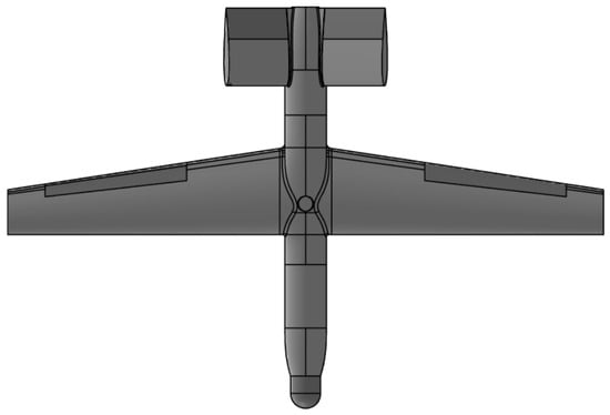
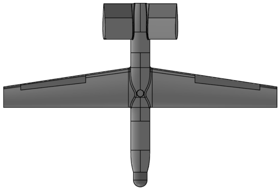
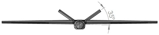
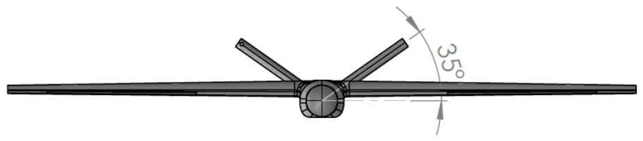
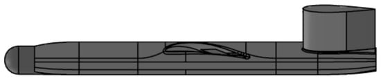
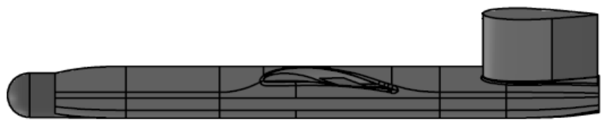
To demonstrate the proposed methodology, a Class-I fixed-wing UAV developed at the Applied Mechanics Laboratory of the University of Patras, Greece, was selected as the reference platform [24,25,26,27]. The aircraft geometric and aerodynamic characteristics used throughout the study are summarized in Table 1, while the corresponding three-dimensional configuration is presented in Figure 1, Figure 2 and Figure 3. According to the NATO UAV classification scheme, the selected platform belongs to the Class-I Mini UAV category.
Table 1.
Geometric characteristics of the reference UAV used in the analytical methodology, low-fidelity aerodynamic analysis, and CFD verification.
Figure 1.
Top view of the reference UAV used throughout this study, illustrating the overall wing planform, fuselage configuration, and V-tail geometry.
Figure 2.
Front view of the reference UAV showing the V-tail configuration and the dihedral angle adopted in the analytical and numerical investigations.
Figure 3.
Side view of the reference UAV illustrating the fuselage profile, wing, and tail location.
The reference UAV is designed for low-speed cruise flight at 23.7 m/s, corresponding to a Reynolds number of approximately based on the mean aerodynamic chord. All aerodynamic analyses presented in this study were performed under these representative operating conditions.
2.2. V-Tail Design and Sizing Methodologies
This section presents the development of the proposed analytical methodology for the early-stage design and stability assessment of V-tail UAV configurations. First, the classical V-tail design approach of Purser and Campbell is briefly reviewed. Subsequently, the proposed methodology is developed by combining the V-tail theory of Purser and Campbell [8] with the aircraft stability and control framework presented by Napolitano [23]. Finally, the methodology is verified using low- and high-fidelity aerodynamic analyses. For clarity, all symbols, subscripts, and aerodynamic-derivative notation used in Equations (1)–(26) are summarized in Appendix A, Table A1, Table A2 and Table A3. Unless otherwise indicated, the aerodynamic derivatives are expressed per radian.
2.2.1. Classical V-Tail Design Methodology
Purser and Campbell [8] proposed an analytical methodology for estimating V-tail geometric characteristics based on required aircraft stability and control derivatives. The methodology relates the V-tail geometry, control effectiveness, and stability derivatives through Equations (1)–(13). Although widely used, the method assumes that the target stability and control derivatives are already known, which limits its applicability during conceptual design.
Using the above stability and control relationships, the principal V-tail design parameters can be determined from the following expressions:
Once the V-tail dihedral angle has been determined from Equation (9), the required V-tail area ratio can be calculated from either the longitudinal-stability requirement or the directional-stability requirement. The corresponding expressions are given by Equations (10) and (11), respectively.
Equations (10) and (11) are not identical. Equation (10) is obtained by rearranging the longitudinal-stability relationship of Equation (5), whereas Equation (11) is obtained by rearranging the directional-stability relationship of Equation (6). For a consistent set of prescribed stability derivatives and a V-tail dihedral angle satisfying Equation (9), the two expressions theoretically provide the same required V-tail area ratio. Therefore, either Equation (10) or Equation (11) may be used to determine the V-tail area within the classical design procedure.
The control-effectiveness requirement is subsequently evaluated independently for the longitudinal and directional control conditions. The values required to satisfy the prescribed pitching- and yawing-moment derivatives are denoted by and , respectively:
Equations (12) and (13) are also not identical. Equation (12) determines the control-effectiveness parameter required to satisfy the longitudinal pitching-control requirement, whereas Equation (13) determines the value required to satisfy the directional yawing-control requirement. The two calculated values are not generally equal. Following the design procedure of Purser and Campbell [8], the larger value is retained:
The selected value of is then substituted into Equations (7) and (8) to calculate the final pitching- and yawing-control derivatives. Consequently, one of the resulting control derivatives may be larger in magnitude than the corresponding prescribed minimum requirement, ensuring that both control requirements are satisfied.
It should be noted that Equations (9)–(14) are presented in this subsection to summarize and clarify the classical V-tail design procedure of Purser and Campbell [8]. These equations were not used to calculate the analytical results of the present study. The results were obtained using the proposed methodology described by Equations (15)–(26).
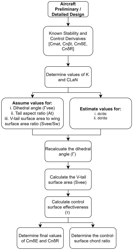
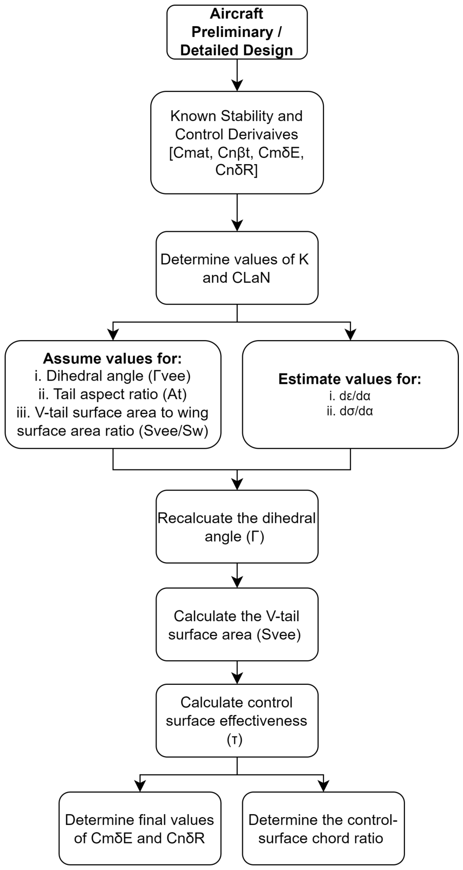
The complete design procedure is summarized in Figure 4.
Figure 4.
Flowchart of the classical V-tail design methodology proposed by Purser and Campbell [8], illustrating the sequence of calculations used to determine V-tail geometry and control effectiveness from prescribed stability and control derivatives.
Although the methodology provides an efficient procedure for V-tail sizing, it assumes that the required stability and control derivatives are known a priori. Consequently, the method is generally applicable after the preliminary sizing of the aircraft has been completed, limiting its direct use during the conceptual design phase.
2.2.2. Development of the Proposed Methodology
The objective of the proposed methodology is to enable the direct estimation of V-tail geometry and associated stability and control derivatives during the conceptual and preliminary design phases of a Class-I UAV. Unlike the methodology proposed by Purser and Campbell, which requires the target aircraft stability and control derivatives as inputs, the present approach combines conventional aircraft sizing principles with semi-empirical stability and control formulations to estimate both the V-tail geometry and its aerodynamic characteristics directly from the aircraft geometric parameters.
The methodology is based on the conventional aircraft conceptual design process described by Raymer [28] and the aircraft stability and control formulations presented by Napolitano. Following the conceptual sizing of the aircraft, the equivalent horizontal and vertical tail characteristics are transformed into an equivalent V-tail configuration. Subsequently, the stability and control derivatives of the resulting V-tail are estimated analytically, allowing the designer to proceed directly to the preliminary design stage without requiring prior aerodynamic analyses or predefined stability derivatives.
The proposed methodology is developed under the following assumptions:
- Low-speed incompressible flow conditions
- Linear aerodynamic behavior within the operating range
- Small perturbation theory
- Symmetric V-tail geometry
- Negligible aeroelastic effects
- Conventional tail-volume coefficient relationships remain applicable
- The V-tail replaces an equivalent conventional horizontal and vertical tail configuration
Following the conceptual sizing of the aircraft, the geometric characteristics of the V-tail are determined from the equivalent horizontal and vertical tail geometry.
According to the equivalent-tail formulation proposed by Purser and Campbell [8], the projected horizontal and vertical tail areas of the V-tail are related to the total V-tail reference area through
and
By summing the projected horizontal and vertical components and using the trigonometric identity , the total V-tail reference area is obtained as
while the V-tail dihedral angle is estimated from:
where () and () denote the equivalent horizontal and vertical tail areas, respectively, and () and () represent their corresponding spans.
Equations (15) and (16) provide the initial geometric characteristics of the V-tail directly from the equivalent conventional empennage. Once the V-tail geometry has been established, the stability and control derivatives required during the preliminary design phase must be estimated.
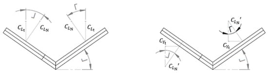
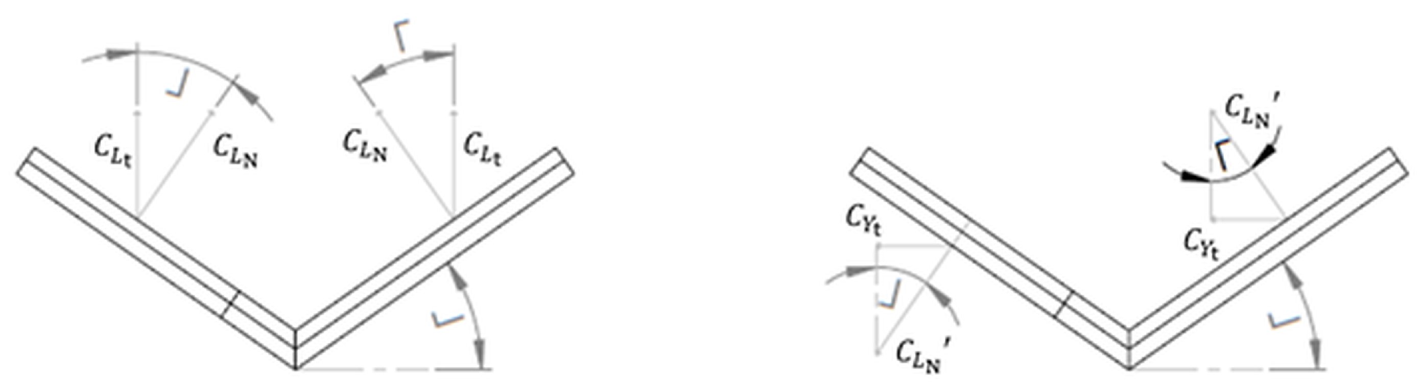
To achieve this, the conventional stability and control relationships presented by Napolitano, originally developed for aircraft equipped with separate horizontal and vertical stabilizers, were reformulated for a V-tail configuration through force decomposition along the inclined tail surfaces. The equivalent V-tail geometry obtained from Equations (15) and (16) was introduced into the conventional stability and control expressions, allowing the aerodynamic forces generated by the V-tail to be resolved into their longitudinal and lateral–directional components. As a result, the conventional stability and control derivatives were transformed into equivalent V-tail expressions, leading to the analytical relationships presented in Equations (17)–(26) as well as in Figure 5. This reformulation constitutes the principal methodological contribution of the present work.
Figure 5.
Relations of angles and force coefficients for V-tail in pitch and sideslip [8].
The lift-curve slope of the V-tail and the corresponding ruddervator effectiveness are estimated from:
where,
The isolated side-force derivatives of the V-tail are estimated from:
The longitudinal stability and control derivatives are then calculated as:
The lateral–directional stability and control derivatives are obtained through:
Equations (17)–(26) provide analytical estimates of the principal longitudinal and lateral–directional stability and control derivatives required during the preliminary design phase. Unlike the methodology of Purser and Campbell, the proposed approach does not require prior knowledge of the target aircraft’s stability and control derivatives. Instead, these quantities are estimated directly from the aircraft geometry and V-tail characteristics, allowing the methodology to be applied during the conceptual and early preliminary design stages.
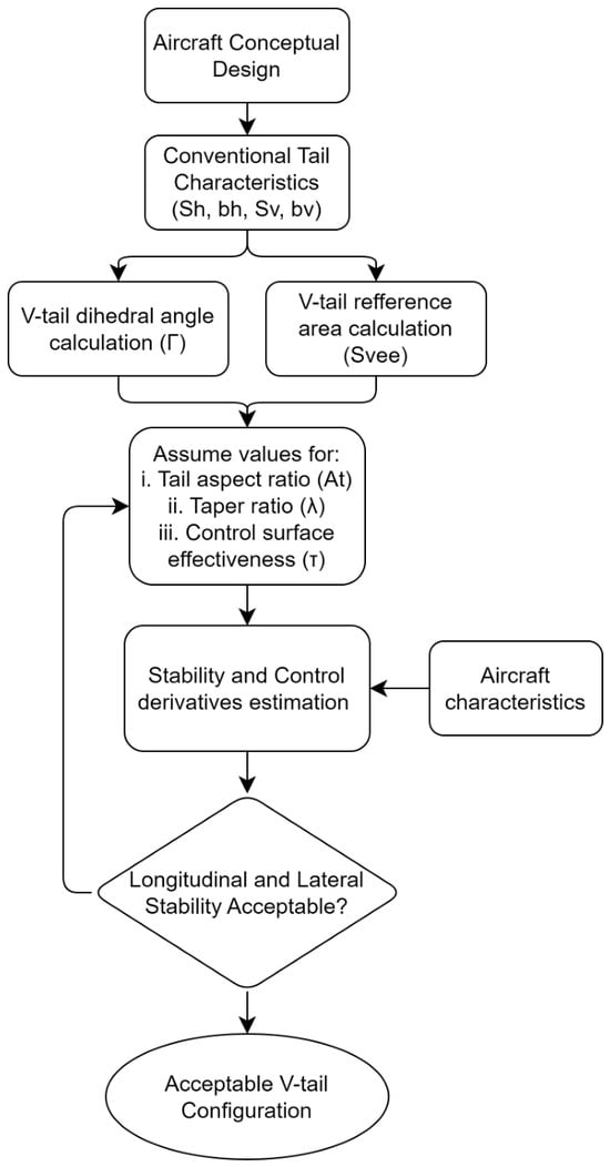
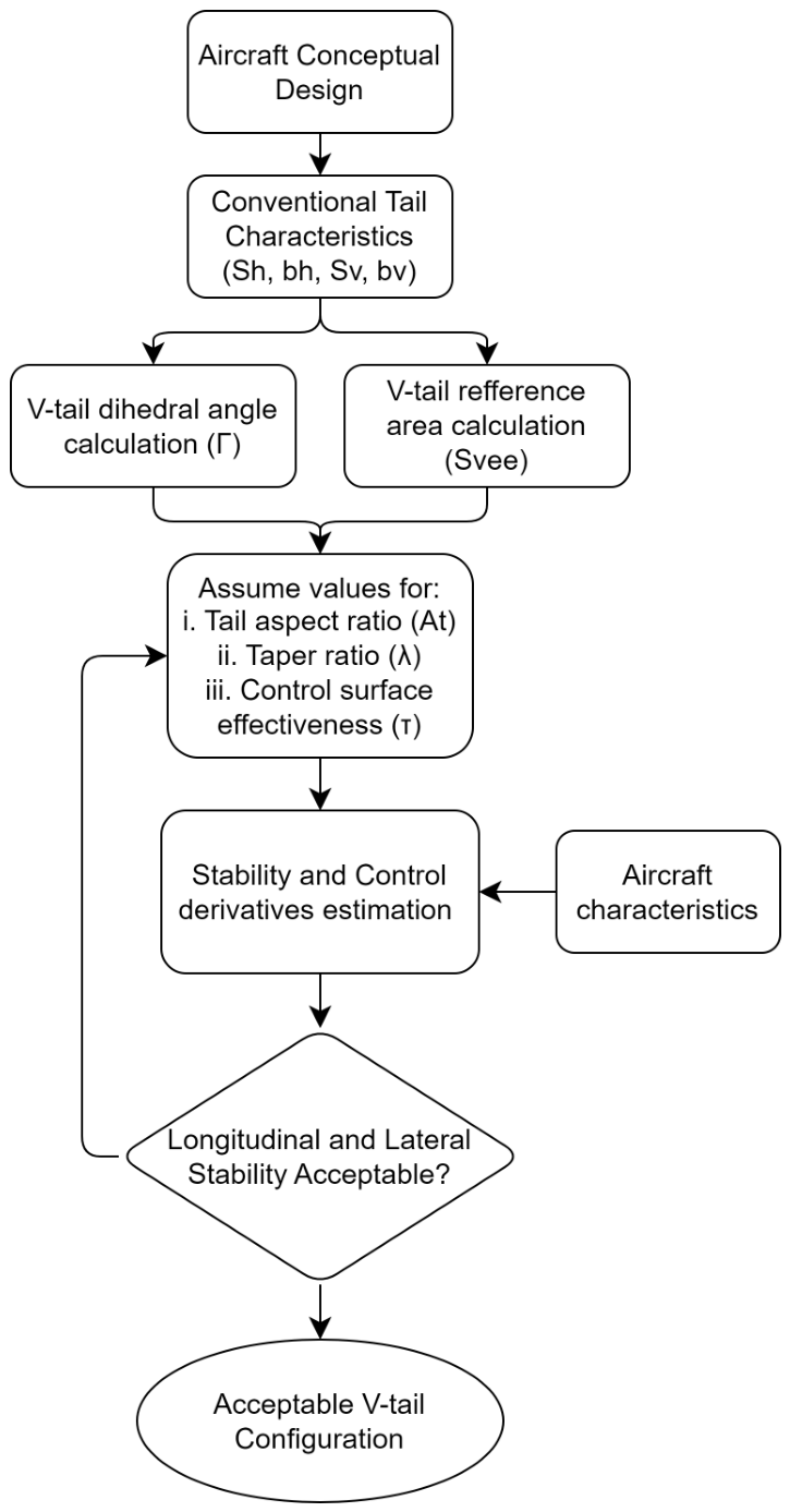
The complete workflow of the proposed methodology is summarized in the following Figure 6:
Figure 6.
Flowchart of the proposed analytical methodology for the conceptual and preliminary design of V-tail Class-I UAVs, showing the estimation of V-tail geometry, stability derivatives, and the iterative assessment of acceptable longitudinal and lateral stability.
2.2.3. Low-Fidelity Aerodynamics
The stability and control derivatives predicted by the proposed analytical methodology were initially assessed using a low-fidelity aerodynamic model. For this purpose, the XFLR5 software package was employed, which provides aerodynamic analysis capabilities based on the Vortex Lattice Method (VLM) and the Three-Dimensional Panel Method. The theoretical background and implementation of these methods are described in detail by Katz and Plotkin [29].
Initially, the isolated V-tail configuration was analyzed using both the Three-Dimensional Panel Method and the VLM approach in order to evaluate the principal aerodynamic characteristics and stability derivatives. The results obtained from the two methods showed negligible differences, indicating that the VLM approach provides sufficient accuracy for the present low-speed UAV application. Consequently, the VLM method was selected for all subsequent analyses due to its reduced computational cost.
Following the isolated V-tail assessment, the complete UAV geometry was implemented in XFLR5 and analyzed using the VLM solver. The aerodynamic model incorporated the wing, fuselage, and V-tail geometry presented in Section 2.1. Stability and control derivatives were extracted from the linear variation of aerodynamic forces and moments with respect to angle of attack, sideslip angle, and ruddervator deflections.
The resulting aerodynamic derivatives were subsequently compared with the predictions of the proposed analytical methodology and with the high-fidelity CFD results presented in Section 3. The objective of this comparison was to assess the applicability of the proposed methodology during the conceptual and preliminary design stages and to quantify its accuracy relative to commonly used low-fidelity aerodynamic tools.
2.2.4. High-Fidelity Aerodynamics
A UAV model (1:1) was designed to compare numerical results with analytical ones. The dimensions of the computational domain and the boundary conditions were adjusted as possible to the characteristics and the altitude of the UAV operational environment. Simulations were performed with the commercial code ANSYS-Fluent 2025 R1 software [30], resolving Reynolds-Average-Navier-Stokes (RANS) equations, coupled with the Shear Stress Transport (SST) turbulence model.
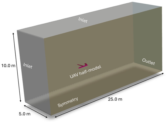
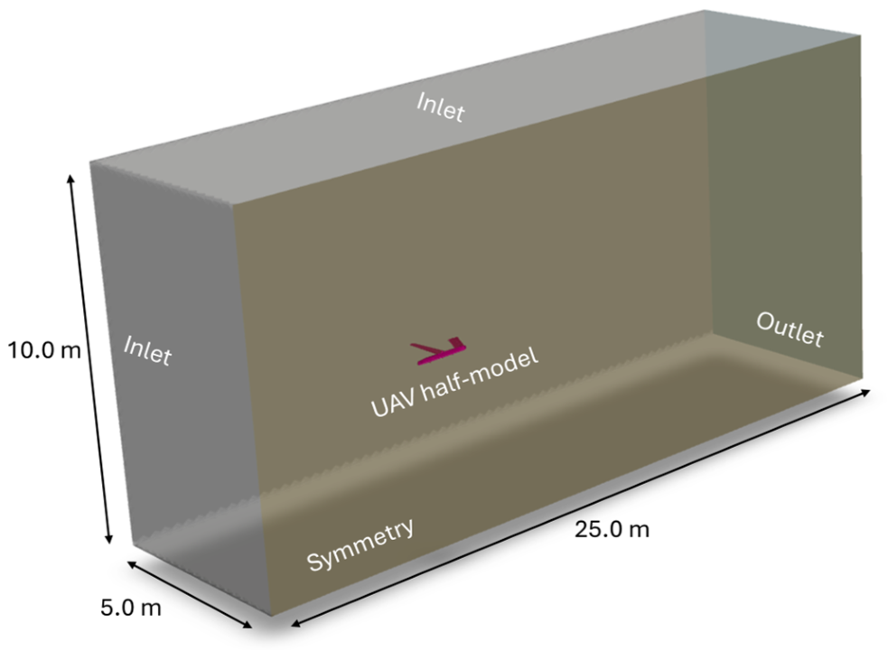
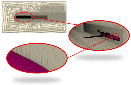
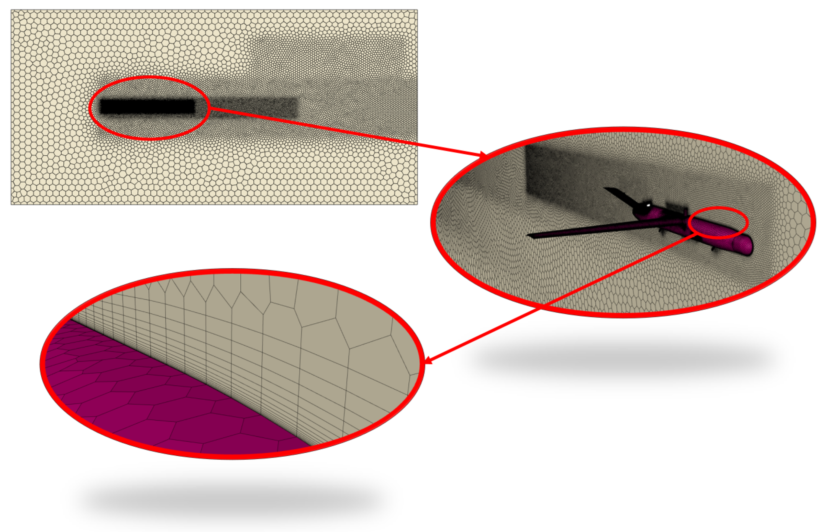
The dimensions of the computational domain for the full UAV model (Figure 7 and Figure 8) were 10.0 × 5.0 × 25.0 m (≥10 × UAV length). Navier-Stokes equations were discretized via the Finite Volume Method (FVM) and solved in terms of the RANS equations, assuming incompressible flow and steady state, with an appropriate mesh resolution. A first cell wall distance, , necessary for capturing the evolution of the boundary layer using RANS turbulence models, in the region of 1 was targeted, resulting in a height of the first layer being set to y = m.
Figure 7.
Computational domain adopted for the CFD simulations, showing the domain dimensions, inlet and outlet boundaries, and the location of the UAV model used for the aerodynamic analyses.
Figure 8.
Computational domain mesh resolution adopted for CFD simulations.
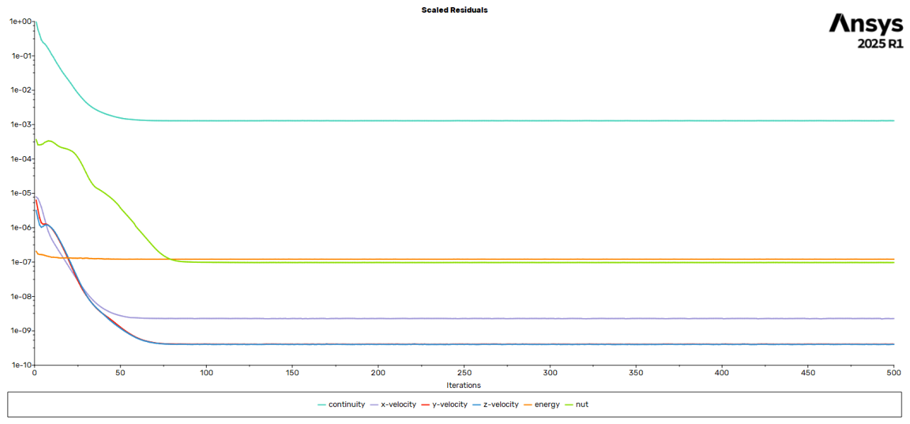
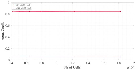
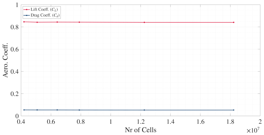
A mesh independence study was carried out, to ensure that the mesh refinement does not affect the solution, and the results are shown in Figure 9. This study gave the size of the mesh elements that were used for all the analyses, with the lowest computational cost. Additional details of the mesh convergence study, together with the residual histories of the CFD analyses, are provided in Table A4 and Table A5 and Figure A1 in Appendix B.
Figure 9.
Mesh independence study showing the variation of lift coefficient () and drag coefficient () with the number of computational cells used in the CFD simulations. The convergence of both coefficients demonstrates that the selected mesh provides mesh-independent results.
For the isolated V-tail model, the dimensions of the computational domain were 2.0 × 2.0 × 6.0 m (≥10 × V-tail MAC). Again, a mesh independence study was carried out for this model, which gave the size of the mesh elements for the isolated V-tail computational grid. The first layer height was set in y = m, resulting in a 1. The SST k-omega turbulence model was used for all analyses, due to the ease in which it models typical high-lift aerodynamic problems.
Pressure and temperature were calculated at the maximum altitude where the UAV will be operated and set to the computational domain. Inlet velocity was set at 23.7 m/s, with Reynolds number equal to , based on UAV MAC. Outlet velocity was set without a pressure gradient difference at the outlet region. Turbulence intensity and turbulence length scale were set to 3.7 and 0.7, respectively, for each boundary condition, according to the UAV length and the operating Reynolds number. The symmetry condition was imposed in the half of the longitudinal plane of each model. The UAV and the isolated V-tail models were treated as Free-slip walls. A wide range of angles of attack, , was examined, ranging from to , as well as for sideslip angles, , ranging from to . Analyses were conducted also for symmetric and antisymmetric ruddervator deflections with . For the analyses with the antisymmetric deflection to ruddervators, a computational domain without symmetry conditions was used.
Furthermore, the stability and control derivatives were extracted using a quasi-static approach. A series of steady-state CFD simulations was performed by introducing small perturbations about the reference flight condition. The derivatives were then determined from the slope of the corresponding aerodynamic coefficient curves. For example, the longitudinal stability derivative was obtained as
which was evaluated from the slope of the linear curve. Similarly, the remaining stability and control derivatives were obtained from the slopes of the corresponding aerodynamic coefficient curves with respect to the appropriate perturbation variable. The corresponding aerodynamic coefficient plots used to determine these derivatives are provided in Figure A2, Figure A3, Figure A4 and Figure A5 in Appendix C for completeness.
3. Results
The stability and control derivatives obtained from the proposed analytical methodology, the classical methodology of Purser and Campbell, the low-fidelity aerodynamic analyses, and the high-fidelity CFD simulations are summarized in Table 2. The CFD results are considered the reference solution for the assessment of the analytical methodologies and the low-fidelity aerodynamic model.
Table 2.
Stability and Control Derivatives (Subscript t denotes derivatives associated with the V-tail only. Derivatives without this notation correspond to the complete aircraft).
The results indicate that the proposed methodology predicts the majority of the longitudinal and lateral–directional stability derivatives with values close to those obtained from the CFD simulations. In particular, the predicted values of , , , , and show good agreement with the CFD results. Similar trends are also observed in the low-fidelity aerodynamic analyses, although larger discrepancies are observed for some lateral–directional derivatives.
The relative errors of the analytical methodologies and the low-fidelity aerodynamic model with respect to the CFD results are presented in Table 3.
Table 3.
Absolute relative error to High-Fidelity aerodynamics results.
The proposed methodology achieved relative errors below 10% for the majority of the evaluated derivatives. The smallest discrepancies were observed for , , and , indicating that the analytical framework accurately captures the primary aerodynamic effects associated with the V-tail configuration.
In contrast, the methodology of Purser and Campbell exhibited larger deviations for several derivatives, particularly those associated with pitch stability and control. These discrepancies are expected since the original methodology was developed for aircraft whose target stability and control derivatives are already known and therefore does not directly address conceptual design applications.
Prediction Accuracy
The largest discrepancy observed in the present study corresponds to the side-force derivative , for which all prediction approaches exhibit relatively large deviations from the CFD results. The proposed methodology yields an error of approximately 42%, while the low-fidelity aerodynamic model and the classical methodology produce similar levels of discrepancy.
The fact that all three approaches demonstrate comparable deviations suggests that the source of the error is not exclusively related to the proposed analytical formulation. Instead, it is likely associated with the modeling of side-force generation and sidewash effects in the presence of the complete aircraft geometry. Contributions from the fuselage, wing-body interaction effects, and nonlinear flow behavior under sideslip conditions may influence this derivative and are not fully captured by the simplified analytical assumptions or the low-fidelity aerodynamic models.
Despite this discrepancy, the proposed methodology demonstrates satisfactory agreement for the remaining longitudinal and lateral–directional stability derivatives, with most errors remaining below 15%. Considering that the methodology is intended for conceptual and early preliminary design applications, this level of accuracy is considered acceptable and comparable to that typically achieved by semi-empirical aircraft design methods.
4. Discussion
The results presented in Table 2 indicate that the proposed analytical methodology predicts the majority of the evaluated stability and control derivatives with satisfactory accuracy. Relative errors with respect to the high-fidelity CFD results remain below 10% for most derivatives, with only two derivatives exhibiting errors of approximately 14% and 17%, respectively. The largest discrepancy corresponds to the side-force derivative , for which the relative error reaches approximately 42%.
It is noteworthy that the proposed methodology consistently provides lower relative errors than both the low-fidelity aerodynamic analyses and the classical methodology of Purser and Campbell for the majority of the investigated derivatives. Furthermore, the relatively large error associated with is observed not only in the proposed methodology but also in the low-fidelity aerodynamic model and the classical analytical approach. This suggests that the discrepancy is likely related to the modeling of side-force generation under sideslip conditions rather than to the proposed methodology itself. Potential sources of error include fuselage contributions, wing-body interaction effects, sidewash modeling assumptions, and nonlinear aerodynamic phenomena that are not fully captured by simplified analytical formulations.
The stability and control derivatives obtained using the methodology of Purser and Campbell exhibit larger deviations from the CFD results for most derivatives, with the exception of , for which an error of approximately 1.5% was obtained. These results are consistent with the intended application of the classical methodology, which assumes that the required aircraft stability and control derivatives are already known and therefore is better suited to preliminary or detailed design stages rather than conceptual design applications. Similarly, while the low-fidelity aerodynamic analyses provide acceptable agreement for several derivatives, four of the evaluated quantities exhibit relative errors exceeding 20%, indicating the limitations of low-fidelity approaches for accurately capturing all stability and control characteristics of the investigated configuration.
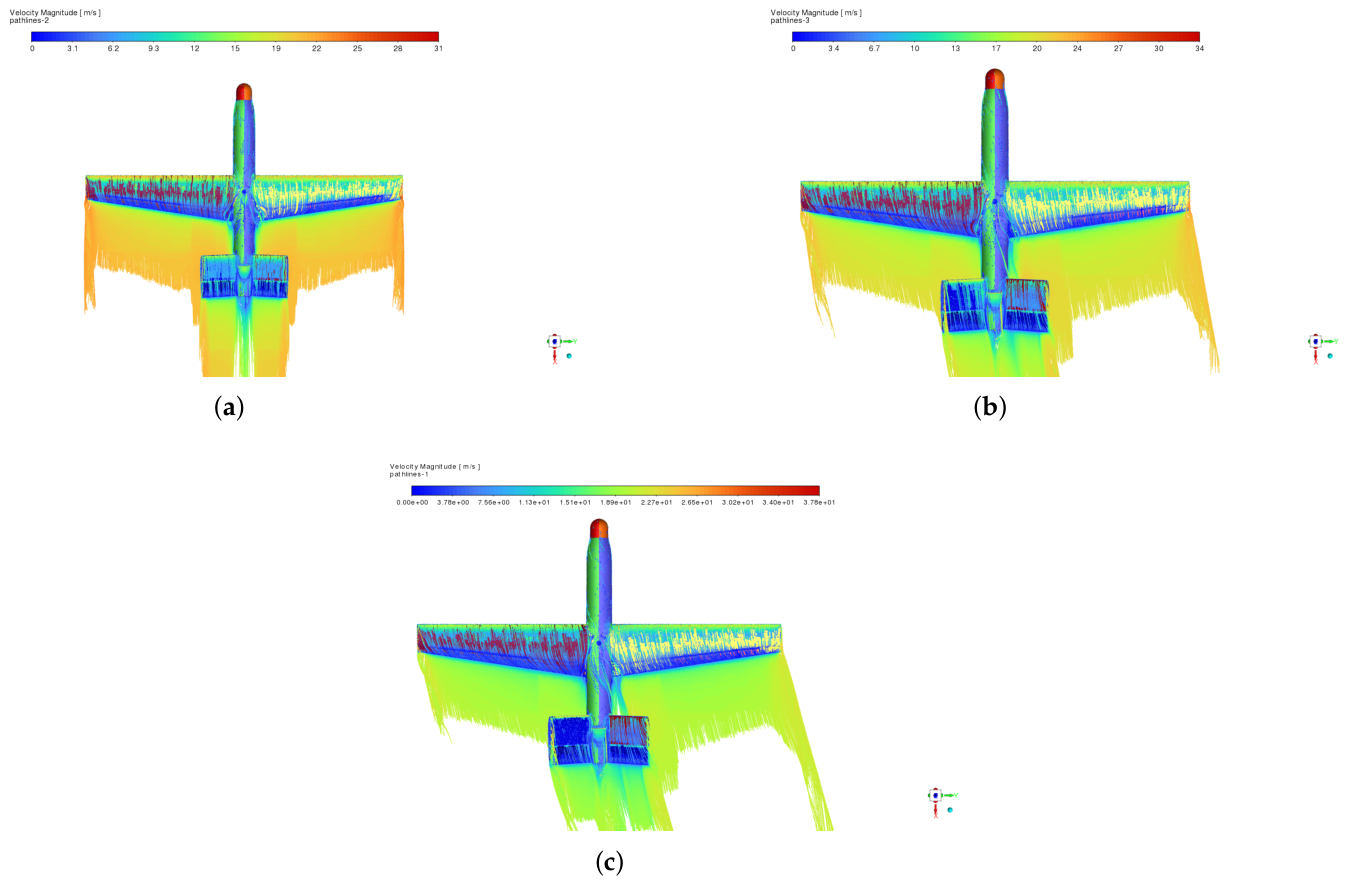
The discrepancies observed between the proposed methodology and the classical analytical models reported in References [8,9,10] are primarily associated with the assumptions adopted during their development. The methodologies presented in these studies were derived either for conventional aircraft configurations or for predefined V-tail geometries, where the required stability and control derivatives are available from experimental measurements, aerodynamic analyses, or previous design iterations. In contrast, the proposed methodology is intended for the conceptual and preliminary design stages and directly estimates these derivatives from the aircraft geometric characteristics through the reformulation of conventional stability and control relationships for an equivalent V-tail configuration. Consequently, differences between the predicted derivatives are expected, particularly for quantities that are strongly influenced by aerodynamic interaction effects that are not fully represented by simplified analytical formulations. These interaction effects are illustrated in Figure A6, Figure A7 and Figure A8 in Appendix C, which demonstrate the influence of sideslip.
An additional advantage of the proposed methodology is the substantial reduction in computational effort compared with aerodynamic analyses. The analytical estimation of the stability and control derivatives requires less than one hour of computational time, whereas the preparation and execution of the low-fidelity aerodynamic analyses required approximately 1–2 days. In contrast, the high-fidelity CFD simulations required approximately 20–25 days, including geometry preparation, mesh generation, solution convergence, and post-processing. Consequently, the proposed methodology offers a significant reduction in design turnaround time while maintaining an acceptable level of accuracy for conceptual and early preliminary design applications.
The present methodology was evaluated for a single Class-I UAV configuration and under the assumptions of linear aerodynamic behavior and low-speed flight conditions. Therefore, its applicability to other UAV classes, unconventional V-tail geometries, and highly nonlinear flight regimes remains to be investigated. Additionally, the present study uses high-fidelity CFD simulations as the reference solution for assessing the proposed analytical methodology. Although CFD provides detailed aerodynamic information and is widely employed during aircraft design, it cannot replace experimental validation. Therefore, the agreement reported between the analytical methodology and the CFD results should be interpreted as numerical verification rather than experimental validation. Experimental investigations, including wind-tunnel testing or flight-test measurements, will be required to fully validate the proposed methodology and quantify its applicability under real operating conditions.
5. Conclusions
In the present study, an analytical methodology for the early-stage design and stability assessment of V-tail Class-I UAV configurations was developed by combining the classical V-tail theory of Purser and Campbell [8] with the aircraft stability and control methodology of Napolitano [23]. The proposed approach enables the direct estimation of V-tail geometry and the corresponding stability and control derivatives during the conceptual and preliminary design phases, eliminating the need for prior knowledge of the target aircraft stability derivatives.
The methodology was demonstrated on a Class-I UAV developed at the Applied Mechanics Laboratory of the University of Patras. The resulting stability and control derivatives were evaluated using both low-fidelity aerodynamic analyses and high-fidelity CFD simulations. Comparison with the CFD results showed that the proposed methodology predicts the majority of the investigated derivatives with satisfactory accuracy, with relative errors below 10% for most cases and generally lower deviations than those obtained using both the classical methodology of Purser and Campbell and the low-fidelity aerodynamic analyses.
An additional advantage of the proposed methodology is the significant reduction in computational effort. The analytical estimation of the stability and control derivatives required less than one hour, compared with approximately 1–2 days for the low-fidelity aerodynamic analyses and 20–25 days for the high-fidelity CFD simulations. Consequently, the methodology provides a practical tool for reducing design turnaround time during the conceptual and early preliminary design stages. All analyses were performed on a workstation equipped with an Intel Core i7 processor (12 cores) and 32 GB RAM. The reported computational times correspond to this hardware configuration and may vary depending on the computational platform.
Overall, the results demonstrate that the proposed methodology constitutes an efficient and sufficiently accurate framework for the preliminary sizing and stability assessment of V-tail Class-I UAV configurations. Future work will focus on extending the validation of the proposed methodology to additional UAV platforms through high-fidelity numerical analyses and experimental investigations, including wind-tunnel testing or flight test measurements. Furthermore, the resulting designs will be evaluated against key stability and control requirements, including take-off rotation, crosswind recovery, spin recovery, and adverse-yaw recovery characteristics.
Author Contributions
Conceptualization, E.N., S.K., V.L. and V.K.; methodology, E.N.; software, E.N. and S.K.; validation, E.N. and S.K.; formal analysis, E.N.; investigation, E.N.; resources, E.N.; data curation, E.N.; writing—original draft preparation, E.N. and S.K.; writing—review and editing, E.N., S.K., V.L. and V.K.; visualization, E.N. and S.K.; supervision, V.L. and V.K.; project administration, E.N., S.K., V.L. and V.K.; All authors have read and agreed to the published version of the manuscript.
Funding
This research received no external funding.
Institutional Review Board Statement
Not applicable.
Informed Consent Statement
Not applicable.
Data Availability Statement
Data are available upon request.
Conflicts of Interest
The authors declare no conflict of interest.
Abbreviations
The following abbreviations are used in this manuscript:
| UAV | Unmanned Aerial Vehicle |
| CFD | Computational Fluid Dynamics |
| MAC | Mean Aerodynamic Chord |
| VLM | Vortex lattice method |
| RANS | Reynolds-averaged Navier-Stokes |
| HT | Horizontal tail |
| VT | Vertical tail |
| RV | Ruddervator |
Appendix A. Nomenclature
Table A1.
Aerodynamic coefficients, angles, and correction parameters.
Table A2.
Aircraft geometry, flow quantities, and auxiliary parameters.
Table A3.
Subscripts and qualifiers used in the aerodynamic notation.
Appendix B. Mesh Convergence Characteristics
Table A4.
Mesh characteristics.
Table A5.
CFD analysis convergence criteria.
Figure A1.
Convergence criteria of mesh independence study.
Appendix C. CFD Results
Figure A2.
V-tail Lift Coeff. vs Angle-of-attack—Isolated V-tail.
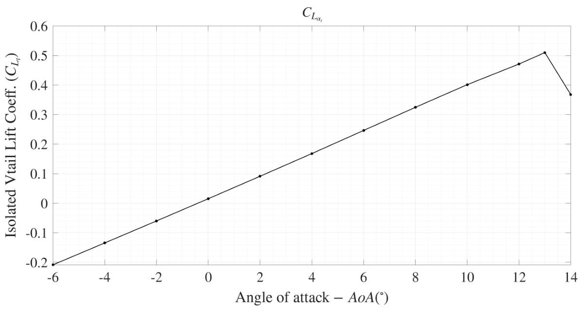
Figure A3.
Lift Coeff. (a) and Pitch Moment Coeff (b) with respect to ruddervator deflection —Installed V-tail.
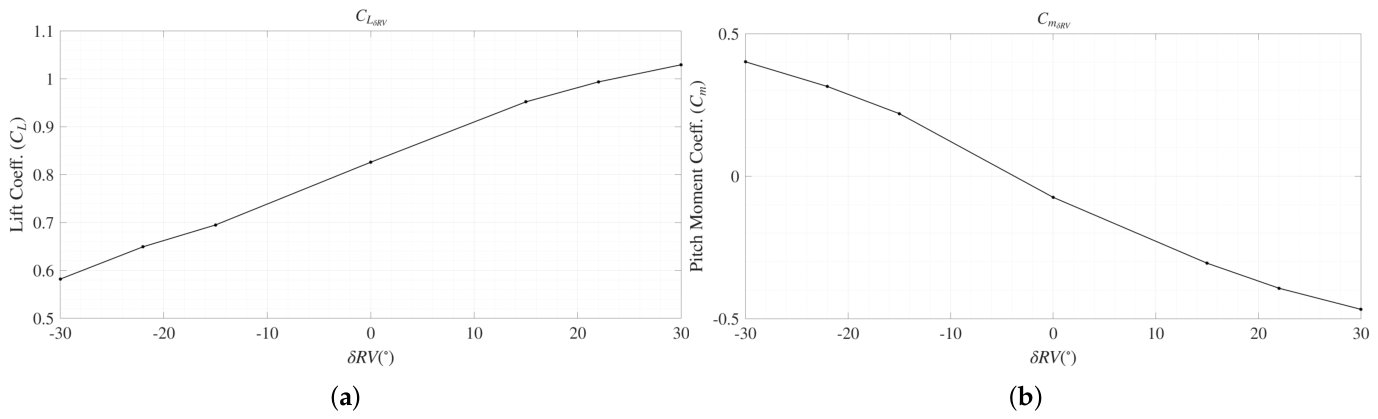
Figure A4.
Side-force Coeff. (a) and Yaw Moment Coeff (b) with respect to ruddervator deflection —Installed V-tail.
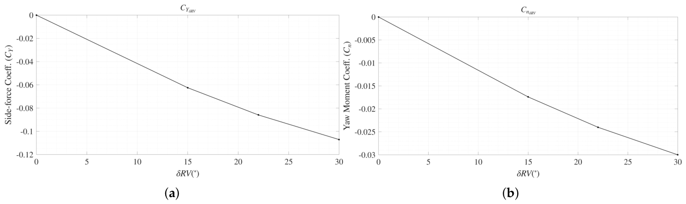
Figure A5.
Side-force Coeff. (a) and Yaw Moment Coeff (b) with respect to sideslip angle —Installed V-tail.
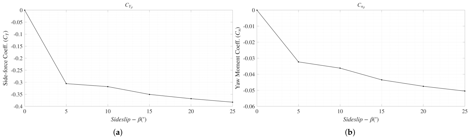
Figure A6.
Pressure Coeff. contours for (a), (b), (c).
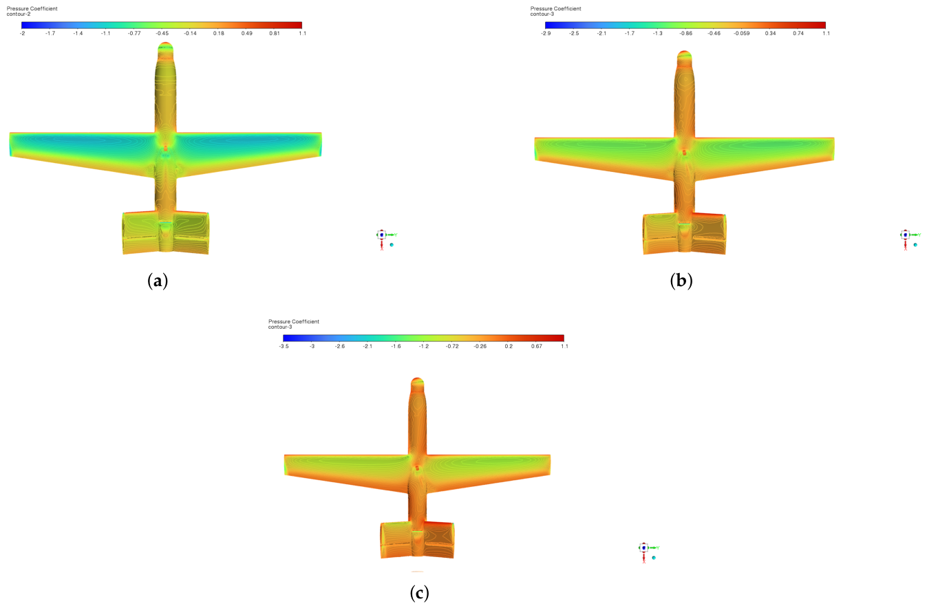
Figure A7.
Static temperature contours for (a), (b), (c).
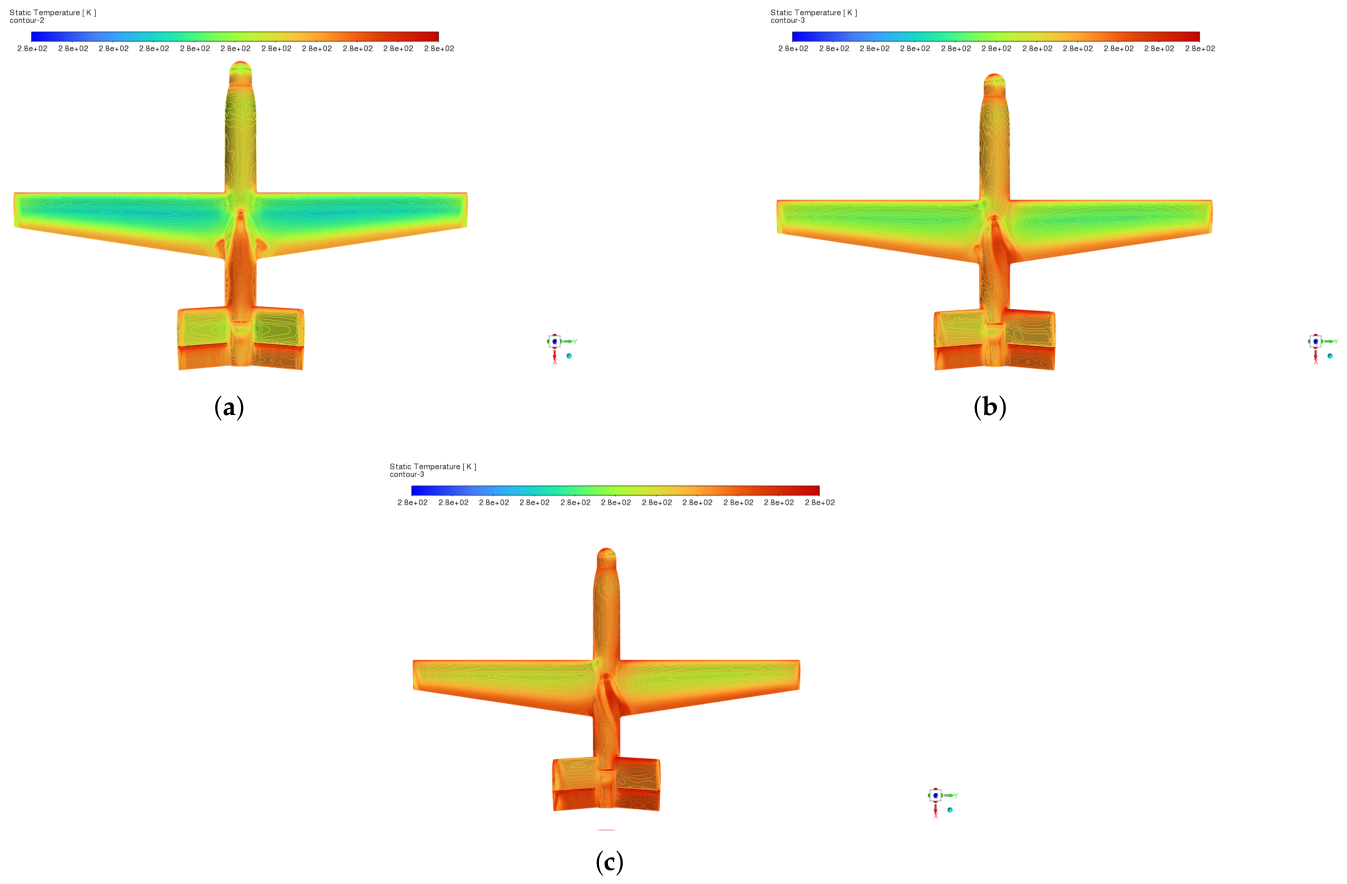
Figure A8.
Velocity pathlines for (a), (b), (c).
References
- Kontogiannis, S.G.; Ekaterinaris, J.A. Design, performance evaluation and optimization of a UAV. Aerosp. Sci. Technol. 2013, 29, 339–350. [Google Scholar] [CrossRef] [Scilit]
- Panagiotou, P.; Kaparos, P.; Salpingidou, C.; Yakinthos, K. Aerodynamic design of a MALE UAV. Aerosp. Sci. Technol. 2016, 50, 127–138. [Google Scholar] [CrossRef] [Scilit]
- Panagiotou, P.; Yakinthos, K. Aerodynamic efficiency and performance enhancement of fixed-wing UAVs. Aerosp. Sci. Technol. 2020, 99, 105575. [Google Scholar] [CrossRef] [Scilit]
- Zhao, A.; Zhang, J.; Li, K.; Wen, D. Design and implementation of an innovative airborne electric propulsion measure system of fixed-wing UAV. Aerosp. Sci. Technol. 2021, 109, 106357. [Google Scholar] [CrossRef] [Scilit]
- Dündar, O.; Bilici, M.; Ünler, T. Design and performance analyses of a fixed-wing battery VTOL UAV. Eng. Sci. Technol. Int. J. 2020, 23, 1182–1193. [Google Scholar] [CrossRef] [Scilit]
- Babu, P.H.; Arthurs, R.S.A.; Basha, S.M.; Sadiq, P. Design and Analysis of V-Tail Unmanned Air Vehicle (UAV) for Surveillance Application. Int. J. Eng. Trends Technol. 2016, 32, 119–123. [Google Scholar] [CrossRef] [Scilit]
- Lesalli, P.V. Preliminary Design and Static Stability Analysis of V-Tail Small Fixed-wing Unmanned Aerial Vehicle Purposed for Racing Plane Pilots and Anti-drone Training Platform Using XFLR-5. In Proceedings of the Adisutjipto Aerospace, Science and Engineering International Conference (AASEIC 2024), Yogyakarta, Indonesia, 11–12 December 2024; Atlantis Press International BV: Dordrecht, The Netherlands, 2025; pp. 75–87. [Google Scholar] [CrossRef] [Scilit] [PubMed]
- Purser, P.E.; Campbell, J.P. Experimental Verification of a Simplified Vee-Tail Theory and Analysis of Available Data on Complete Models with Vee Tails; Technical Report NACA 823; National Advisory Committee for Aeronautics: Washington, DC, USA, 1945. [Google Scholar]
- Polhamus, E.C.; Moss, R.J. Wind-Tunnel Investigation of the Stability and Control Characteristics of a Complete Model Equipped with a Vee Tail; Technical Report NACA TN-1478; National Advisory Committee for Aeronautics: Washington, DC, USA, 1947. [Google Scholar]
- Schade, R.O. Effect of Geometric Dihedral on the Aerodynamic Characteristics of Two Isolated Vee-Tail Surfaces; Technical Report NACA TN-1369; National Advisory Committee for Aeronautics: Washington, DC, USA, 1947. [Google Scholar]
- Phillips, W.F.; Hansen, A.B.; Nelson, W.M. Effects of Tail Dihedral on Static Stability. J. Aircr. 2006, 43, 1829–1837. [Google Scholar] [CrossRef] [Scilit]
- Abzug, M.J. V-Tail Stalling at Combined Angles of Attack and Sideslip. J. Aircr. 1999, 36, 729–731. [Google Scholar] [CrossRef] [Scilit]
- García-Hernández, L.; Cuerno, C.; Pérez-Cortés, M. Dynamics and Failure Models for a V-Tail Remotely Piloted Aircraft System. J. Guid. Control Dyn. 2017, 41, 1–9. [Google Scholar] [CrossRef] [Scilit]
- Zhang, G.Q.; Yu, S.C.M.; Chien, A.; Xu, Y. Investigation of the Tail Dihedral Effects on the Aerodynamic Characteristics for the Low Speed Aircraft. Adv. Mech. Eng. 2013, 5, 308582. [Google Scholar] [CrossRef] [Scilit]
- Musa, N.A.; Mansor, S.; Ali, A.; Wan Omar, W.Z.; Abdul Latif, A.; Perumal, K. Effects of Aircraft Tail Configurations on Sensitivity to Yaw Disturbances. Appl. Mech. Mater. 2014, 629, 197–201. [Google Scholar] [CrossRef] [Scilit]
- Musa, N.A.; Mansor, S.; Ali, A.; Che Man, M.H. Effect of Tail Dihedral Angle on Lateral Directional Stability due to Sideslip Angles. In Proceedings of the 53rd AIAA Aerospace Sciences Meeting, Kissimmee, FL, USA, 5–9 January 2015; American Institute of Aeronautics and Astronautics: Reston, VA, USA, 2015. [Google Scholar] [CrossRef] [Scilit]
- Sánchez-Carmona, A.; Cuerno-Rejado, C.; García-Hernández, L. Unconventional tail configurations for transport aircraft. In Proceedings of the Progress in Flight Physics (EUCASS-9), Krakow, Poland, 29 June–3 July 2015; Knight, D., Bondar, Y., Lipatov, I., Reijasse, P., Eds.; EDP Sciences: Les Illys, France, 2017; pp. 127–148. [Google Scholar] [CrossRef] [Scilit]
- Sanchez-Carmona, A.; Cuerno-Rejado, C. Vee-tail conceptual design criteria for commercial transport aeroplanes. Chin. J. Aeronaut. 2019, 32, 595–610. [Google Scholar] [CrossRef] [Scilit]
- Gong, W.; Xia, M.; Yue, L.; Zheng, J.; Zheng, S. Numerical Investigation on Flow Features and Static Stability Characteristics of the V-Tail Aircraft. Flight Dyn. 2021, 39, 19–24. [Google Scholar]
- Georgios, N.; Kollias, M.T.K. Aerodynamics And Static Stability Investigation Of A V-Tail Layout Using Cfd Methods And Various Turbulence Models. Int. J. Eng. Sci. Res. Technol. 2016, 3, 974–991. [Google Scholar] [CrossRef]
- Leshikar, C.; Valasek, J. System Identification Flight Testing of Inverted V-Tail Small Unmanned Air System. In Proceedings of the AIAA SCITECH 2022 Forum, San Diego, CA, USA, 3–7 January 2022; American Institute of Aeronautics and Astronautics: Reston, VA, USA, 2022. [Google Scholar] [CrossRef] [Scilit]
- Liu, J.; Qian, W.; Bai, Y.; Xu, X. Numerical and Experimental Research on Flight Control of a V-Tail Configuration for the Wind Tunnel Model of Aircraft. Aerospace 2022, 9, 792. [Google Scholar] [CrossRef] [Scilit]
- Napolitano, M.R. Aircraft Dynamics; John Wiley & Sons: Chichester, UK, 2011. [Google Scholar]
- Nikolaou, E.; Kilimtzidis, S.; Kostopoulos, V. Winglet Design for Aerodynamic and Performance Optimization of UAVs via Surrogate Modeling. Aerospace 2025, 12, 36. [Google Scholar] [CrossRef] [Scilit]
- Nikolaou, E.; Kilimtzidis, S.; Kostopoulos, V. Multi-Fidelity Surrogate-Assisted Aerodynamic Optimization of Aircraft Wings. Aerospace 2025, 12, 359. [Google Scholar] [CrossRef] [Scilit]
- Nikolaou, E.; Kilimtzidis, S.; Kelverkloglou, P.; Lappas, V.; Kostopoulos, V. Aerostructural Optimization of a Composite Low Reynolds Wing Using Surrogate Modeling Techniques. Drones 2026, 10, 352. [Google Scholar] [CrossRef] [Scilit]
- Nikolaou, E.; Kilimtzidis, S.; Giannaros, E.; Lappas, V.; Kostopoulos, V. Thermal Management of Unmanned Aerial Vehicle Power Systems Using Ducted Forced Convection and Computational Fluid Dynamic Validation. Appl. Sci. 2025, 15, 12508. [Google Scholar] [CrossRef] [Scilit]
- Raymer, D.P. Aircraft Design: A Conceptual Approach, 6th ed.; AIAA Education Series; American Institute of Aeronautics & Astronautics: Reston, VA, USA, 2018. [Google Scholar]
- Katz, J.; Plotkin, A. Preface. In Low-Speed Aerodynamics; Cambridge University Press: Cambridge, UK, 2001; pp. xiii–xiv. [Google Scholar]
- Ansys, Inc. Ansys Fluent User’s Guide; Ansys, Inc.: Canonsburg, PA, USA, 2025. [Google Scholar]

Disclaimer/Publisher’s Note: The statements, opinions and data contained in all publications are solely those of the individual author(s) and contributor(s) and not of MDPI and/or the editor(s). MDPI and/or the editor(s) disclaim responsibility for any injury to people or property resulting from any ideas, methods, instructions or products referred to in the content. |
© 2026 by the authors. Licensee MDPI, Basel, Switzerland. This article is an open access article distributed under the terms and conditions of the Creative Commons Attribution (CC BY) license.