


Abstract
A Realizable k−ε turbulence model and a finite-rate/eddy-dissipation combustion model, together with experimental validation, were used to investigate the flow and combustion characteristics of a novel triple-swirler combustor under multiple operating conditions. The results show that, compared with the conventional baseline configuration, the ring-cooled radial structure induces a third-stage swirl through inclined cooling holes. This swirl regulates the recirculation structure formed by the first two axial swirlers, transforms the core reaction zone from a single large-scale recirculation vortex into multiple vortical structures, forms a low-temperature cooling coverage outside the main reaction zone, and weakens the near-wall entrainment and high-speed sweeping induced by the kidney-shaped vortex pair downstream of the primary holes. The peak temperature of the outer liner is reduced by 14.72%, and the wall-temperature uniformity is improved by 36.02%. The outlet temperature distribution factor (OTDF) decreases by 14.81% and 15.79% under high and medium operating conditions, respectively, indicating an improved outlet temperature field. This study provides engineering guidance for the design of high-performance combustors.
1. Introduction
With aero-engines moving toward higher thrust-to-weight ratios [1,2,3], their hot-section components are increasingly exposed to severe operating conditions [4]. As the core component subjected to the highest thermal load, the combustor directly affects the reliability, economy, and service life of the entire engine. Next-generation combustors must satisfy key technical requirements, including stable operation over a wide operating envelope, effective liner thermal protection, a uniform outlet temperature field, and low emissions [5]. Triple-swirler combustion technology has become a mainstream approach for organizing combustion at high fuel-air ratios [6]. Owing to its staged swirl structure, it can enhance fuel-air mixing, stabilize the flame, and improve residence-time control in the primary zone, and has therefore attracted considerable research interest. Mehta et al. [7] and Xu and Liu [8] confirmed, through CFD simulation and experiments, respectively, that a triple-swirler configuration can improve combustor combustion efficiency. Zhou et al. [9] investigated the effects of the swirl numbers of the inner and outer pilot swirlers on the flame structure in a triple-swirler combustor. Jiang et al. [10] used two-dimensional particle image velocimetry (2D-PIV) to conduct experiments on a simplified three-stage swirler combustor model and revealed the influence of the inner-stage swirl number on the three-stage swirling flow-field structure. These studies demonstrate that triple-swirler combustion technology offers clear advantages in efficient combustion, flame stability, and aerodynamic organization. However, its structural complexity, high cost, and relatively large radial size restrict its application in compact combustors.
To address these limitations, Cheng et al. [11] proposed a novel triple-swirler combustor based on a ring-cooled radial structure. Unlike a conventional triple-swirler combustor, in which three independent swirlers are used to organize the staged swirling flow, the third-stage swirl in the present configuration is generated by cooling air from the annular cavity of the dual axial-swirler mounting seat. This configuration also forms a near-wall low-temperature film. Therefore, the structure innovatively integrates third-stage swirl generation, primary-zone mixing, and liner thermal protection within a limited radial space. However, the coupling mechanism between the ring-cooled radial structure and the swirl organization has not been sufficiently clarified. Recent studies on cooling-hole diameter, film/effusion cooling, and swirl-stabilized combustors have shown that local coolant mixing significantly affects wall heat flux, outlet temperature distribution, and the interaction between the high-temperature core flow and near-wall flow [12,13,14,15,16].
Therefore, this study uses the Realizable k−ε turbulence model and the finite-rate/eddy-dissipation combustion model to systematically analyze the flow characteristics, liner thermal load, and temperature distribution of the novel combustor under different operating conditions. Particular emphasis is placed on revealing the synergistic mechanism between the ring-cooled radial structure and swirl organization. The results provide theoretical support and engineering reference for the optimized design of high-performance combustors.
2. Computational Model and Boundary Conditions
2.1. Geometric Model
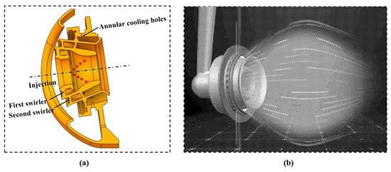
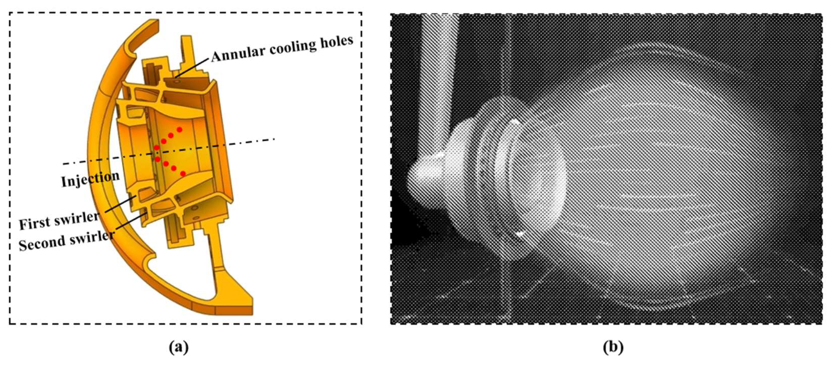
Figure 1a,b show the central sectional view and schematic of the head structure of the novel triple-swirler combustor, respectively. The combustor head consists of a dual axial swirler and a ring-cooled radial structure. The ring-cooled radial structure is composed of inclined holes arranged on the swirler mounting seat. When cooling air enters the combustor through these inclined holes, a third-stage swirl is generated.
Figure 1.
Sectional view and schematic of the head structure of the novel triple-swirler combustor: (a) sectional view of the combustor head structure [17]; (b) schematic of the combustor head structure [18].
2.2. Computational Model
The gas in the combustor is in a high-speed compressible flow state with heat transfer. To ensure reproducibility of the model description, the gas phase is treated as a Newtonian fluid satisfying the ideal-gas equation of state. Three-dimensional steady compressible reacting-flow governing equations are solved, including the energy, continuity, and momentum equations:
where is density, E denotes the total energy per unit mass of the fluid, v stands for the fluid velocity, p signifies the fluid pressure, hj indicates the specific enthalpy of the jth component, Jj refers to the diffusion flux of the jth component, Sh is the energy source term, representing the energy generation per unit volume, and Sm is the mass source term.
The Realizable k−ε two-equation turbulence model is adopted. The transport equations for turbulent kinetic energy and turbulence dissipation rate are given by Equations (4) and (5), respectively. This model is a RANS two-equation model based on the Boussinesq eddy-viscosity assumption, in which the Reynolds stresses are closed using an isotropic eddy-viscosity relation with the mean strain rate. Therefore, its ability to resolve turbulence anisotropy, strong curvature effects, vortex-core precession, and transient large-scale unsteady structures in strongly swirling combustors is limited [19,20]. However, the present study focuses on the relative variations in the flow field, temperature field, and wall thermal load of the novel swirler combustor rather than on the detailed evolution of transient vortical structures. Compared with other models, the Realizable k−ε model has advantages in predicting spreading rates and swirling flows and has shown good accuracy in many numerical studies [21,22,23]. It is therefore suitable for the flow simulation of the combustor considered here.
where k represents turbulent kinetic energy, denotes the turbulent dissipation rate, uj is the velocity component in the j direction, μ is the molecular viscosity coefficient, μt is the turbulent viscosity coefficient, σk is the turbulent Prandtl number for turbulent kinetic energy k, σε is the turbulent Prandtl number for the turbulent dissipation rate , Gk is the term representing the production of turbulent kinetic energy due to the mean velocity gradient, Gb is the term representing the production of turbulent kinetic energy due to buoyancy, YM is the term accounting for the effect of pulsating expansion on the dissipation rate in compressible turbulence, and Sk is the source term for turbulent kinetic energy k, Sε is a user-defined source term for the turbulent dissipation rate , C1 is a model function related to the local mean strain rate, C2, C1ε, and C3ε are empirical constants in the model, dimensionless, and are not further modified in this study [19]; v is the kinematic viscosity; Sij represents the components of the mean strain-rate tensor, reflecting the deformation rate of fluid parcels.
Combustion is modeled using the finite-rate/eddy-dissipation model, and aviation kerosene is represented by the empirical surrogate component C12H23. The model simultaneously calculates the finite-rate chemical reaction rate based on the Arrhenius form and the turbulence-mixing-controlled rate based on the Magnussen eddy-dissipation model, and the smaller of the two is taken as the local reaction rate [24]. The global combustion reaction is treated as a one-step complete oxidation reaction, C12H23 + 17.75O2→12CO2 + 11.5H2O. This mechanism is an engineering simplification of real aviation-kerosene chemistry. It can reasonably describe the overall heat-release process, but it cannot accurately resolve intermediate species, pollutant formation, or detailed reaction pathways [25,26]. In addition, because the eddy-dissipation model controls the reaction rate through the turbulent mixing time scale, its prediction depends on the turbulence model’s ability to capture the recirculation zones, shear layers, and mixing intensity [27]. Therefore, the model may introduce errors in local peak temperature and the extent of high-temperature regions. Nevertheless, the present study focuses on the relative variations in the mean flow and temperature fields of the novel triple-swirler combustor rather than on detailed chemical pathways or pollutant formation. The finite-rate/eddy-dissipation model is computationally stable and well suited for engineering applications, making it appropriate for the present multi-condition structural comparison. The two-phase flow is simulated using the discrete phase model (DPM). Liquid-phase atomization is specified using droplet particles and a Rosin-Rammler size distribution. The spray cone angle and velocity are determined from nozzle test data, with a spray cone angle of 50 deg and a velocity magnitude of 50 m/s. Gas-liquid interaction is modeled using a stochastic particle-tracking model, which can effectively predict fuel-spray transport, evaporation, and gas-liquid coupling in the combustor [28,29].
2.3. Boundary Conditions
A mass-flow inlet is specified at the combustor inlet. The inlet turbulence intensity is set to 5%, which is a commonly adopted engineering value for combustor CFD simulations and satisfies the requirements of engineering calculations. The hydraulic diameter is 99.88 mm, and the remaining conditions are specified according to the experimental measurements. The inlet boundary conditions for the operating cases are listed in Table 1.
Table 1.
Inlet boundary conditions.
A pressure outlet boundary is applied at the combustor exit. The total pressure loss of the combustor is set to 4%, and the total bleed-air ratio is 19.4%, including 9% for the outer annulus and 10.4% for the inner annulus. These parameters are determined based on experimental data [17]. The outlet boundary conditions for each operating condition are listed in Table 2.
Table 2.
Outlet boundary conditions.
To accurately describe the coupling among gas-side convective heat transfer, wall conduction, and coolant-side heat transfer, the wall thermal boundary condition is treated using a conjugate heat transfer approach. This method accounts for the coupled effects of gas-side heat transfer, solid conduction, and coolant-side heat transfer and is an important approach for predicting liner wall temperature [30].
The combustor-flow simulation uses a steady, pressure-based coupled solver, and the parameters are discretized using a second-order upwind scheme. The calculation is considered converged when the residuals of all variables fall below 0.001 and monitored variables, such as surface temperature, become stable.
2.4. Mesh Generation and Grid-Independence Verification
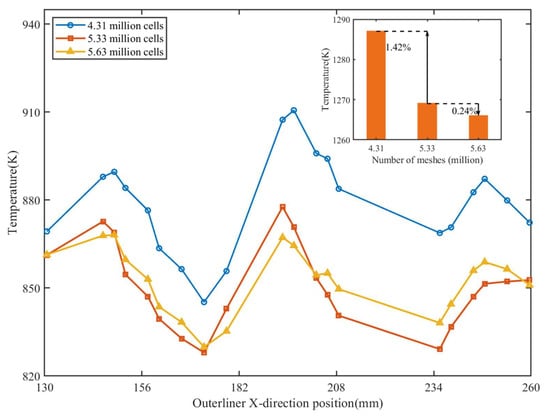
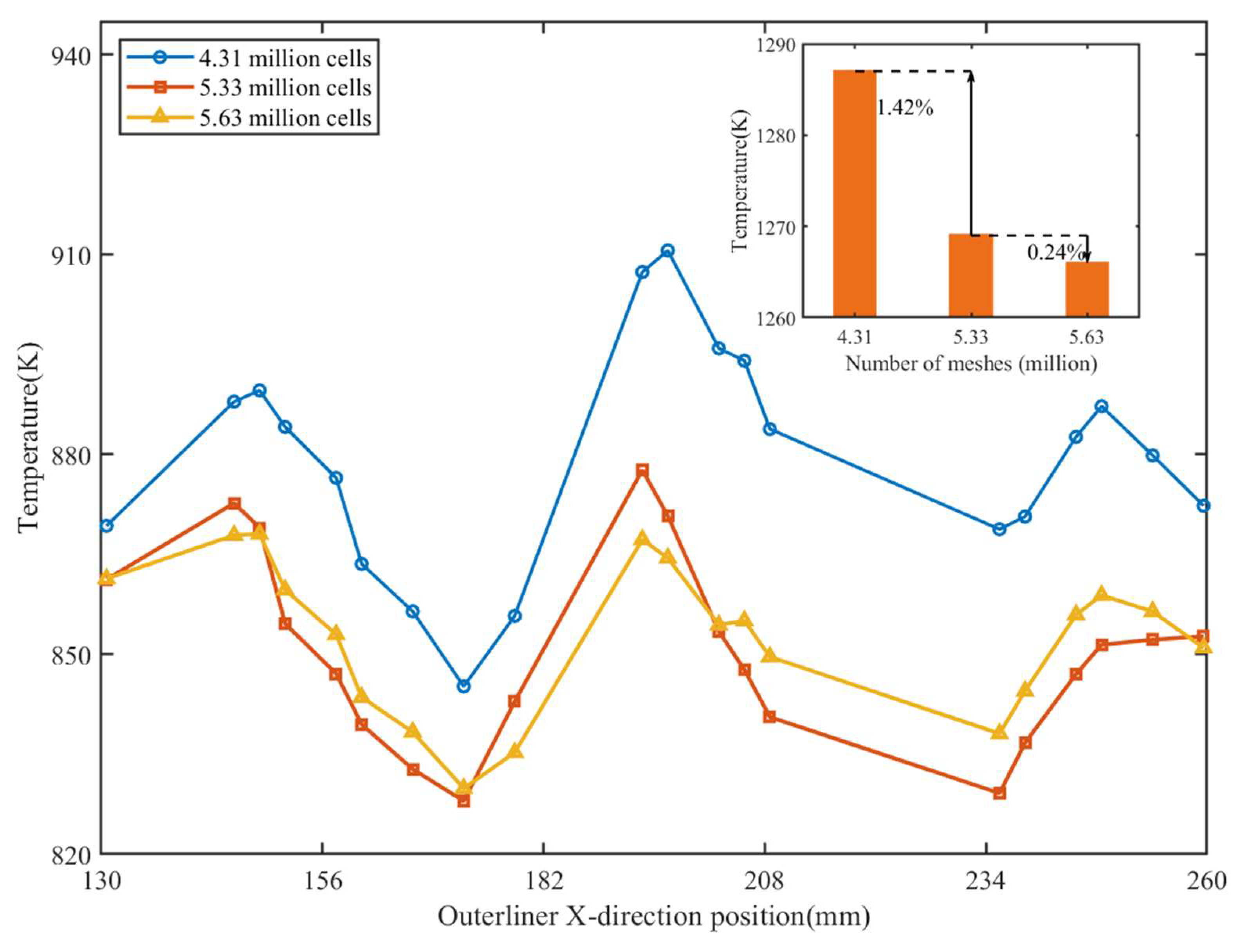
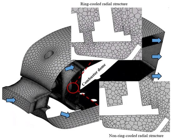
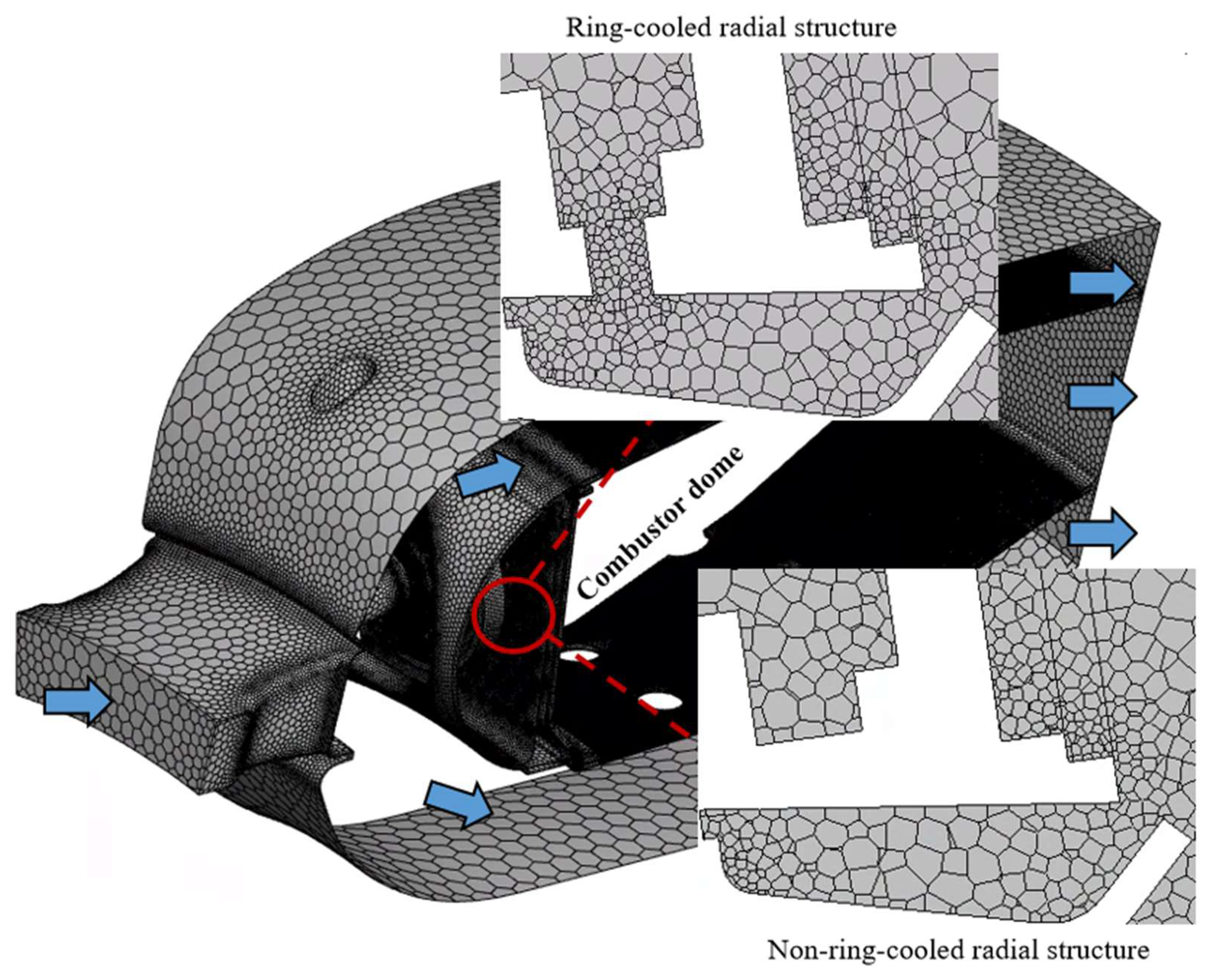
The combustor is discretized using polyhedral meshes. The small cooling-hole regions on the wall are locally refined to ensure y+ approximately 1 and satisfy the near-wall requirements of the turbulence model. To balance computational accuracy and cost, three meshes containing 4.31 million, 5.33 million, and 5.63 million cells are generated. Compared with the 4.31-million-cell mesh, the 5.33- and 5.63-million-cell meshes show more consistent temperature trends at different liner locations. When the cell count is increased from 5.33 million to 5.63 million, the maximum wall temperature changes by only 0.24%, indicating sufficient grid resolution, as shown in Figure 2. Therefore, the 5.33-million-cell mesh is used as the final computational model, as shown in Figure 3.
Figure 2.
Wall temperatures at different liner locations and maximum wall temperature as functions of mesh size.
Figure 3.
Mesh generation.
2.5. Experimental Validation
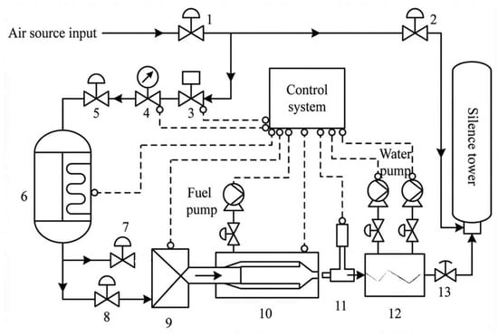
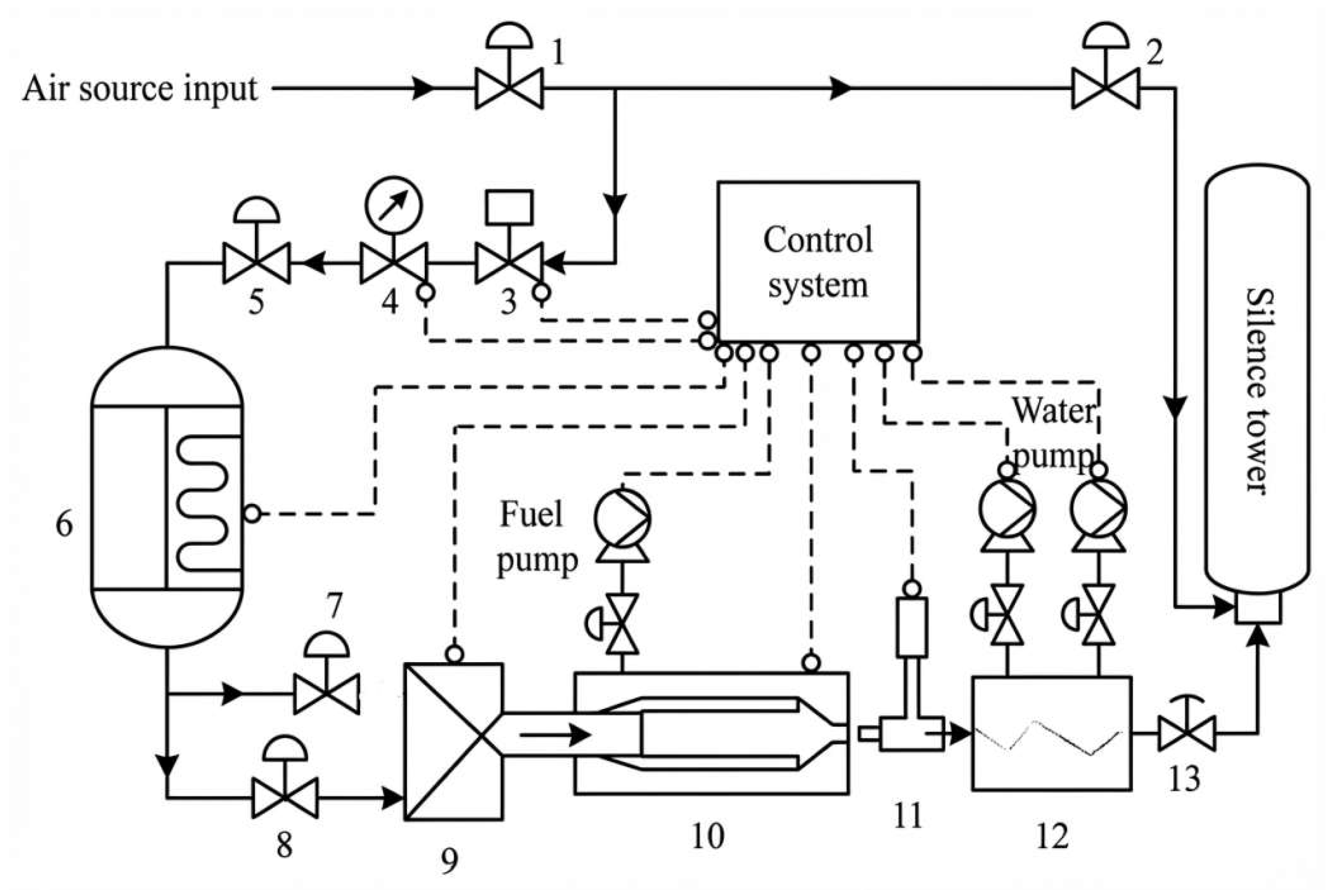
To ensure the accuracy and reliability of the numerical results, experimental validation was conducted through systematic measurements of the combustor outlet temperature field. The test platform consisted of six functional modules: a high-pressure air supply, thermal conditioning, fuel supply, cooling loop, combustor test article, and data acquisition system, as shown in Figure 4. The main airflow was accurately metered using a high-precision orifice flowmeter and then heated by an electric air heater to maintain the inlet temperature at 800 K. At the same time, the exhaust-valve opening was adjusted to accurately reproduce the thermodynamic state at the compressor outlet. RP-3 aviation kerosene was used as the fuel. After pressurization by a booster pump, the fuel flow was accurately metered using a Coriolis mass flowmeter and uniformly atomized and injected through a central air-atomizing nozzle. The high-temperature combustion gas at the combustor outlet was cooled by a water-cooling system and then discharged through an exhaust duct into a silencer.
Figure 4.
Experimental system (1—Main inlet manual valve, 2—Vent valve, 3—Inlet electric control valve, 4—Flow measurement device, 5—Heater inlet valve, 6—Medium-pressure heater, 7—Isolation valve, 8—Inlet valve, 9—Pressure stabilisation device, 10—Test bench, 11—Displacement mechanism, 12—Water injection section, 13—Exhaust valve).
The combustor used a full-annular structural design. A single-point resistance thermometer and static-pressure taps were installed in the inlet section to monitor inlet temperature and wall pressure. The total inlet temperature and total pressure were measured using three combined total-temperature/total-pressure rakes, each containing three measurement points uniformly arranged in the circumferential direction. A rotating traverse mechanism was installed at the combustor outlet and equipped with total-temperature and total-pressure rakes. The outlet temperature field is measured using two total temperature rakes equipped with PtRh30-PtRh6 (type B) thermocouples, with a measurement accuracy of approximately 0.5%. The thermocouples provide high-temperature stability and fast response. A computer-controlled traverse mechanism continuously scanned the combustor outlet section, providing a spatial measurement density of 0.7 points/cm2 and ensuring complete acquisition of the temperature-field distribution. To reduce the influence of radiative heat loss on the measurements, all thermocouples were equipped with dedicated radiation shields. All signals were acquired in real time by a high-precision data acquisition system. A LabVIEW-based control program was used for synchronous traverse control, automatic temperature-data recording, and real-time monitoring of test operation. Data acquisition began after the system had operated steadily for 5 min to ensure the reliability and accuracy of the measurements.
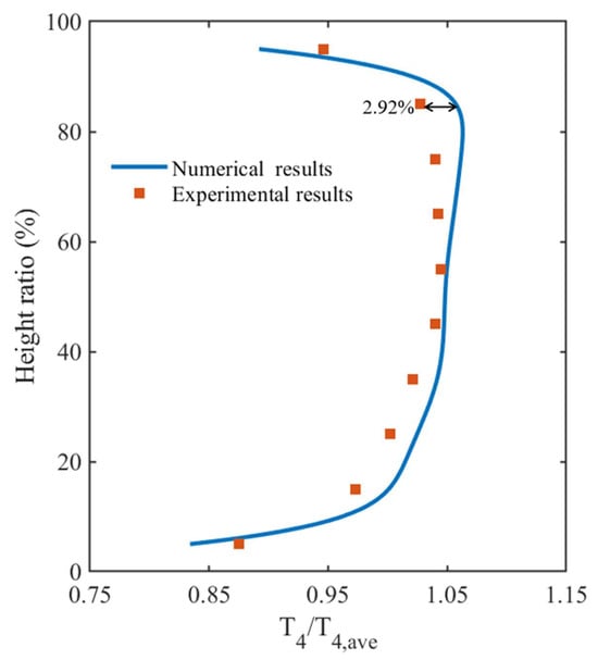
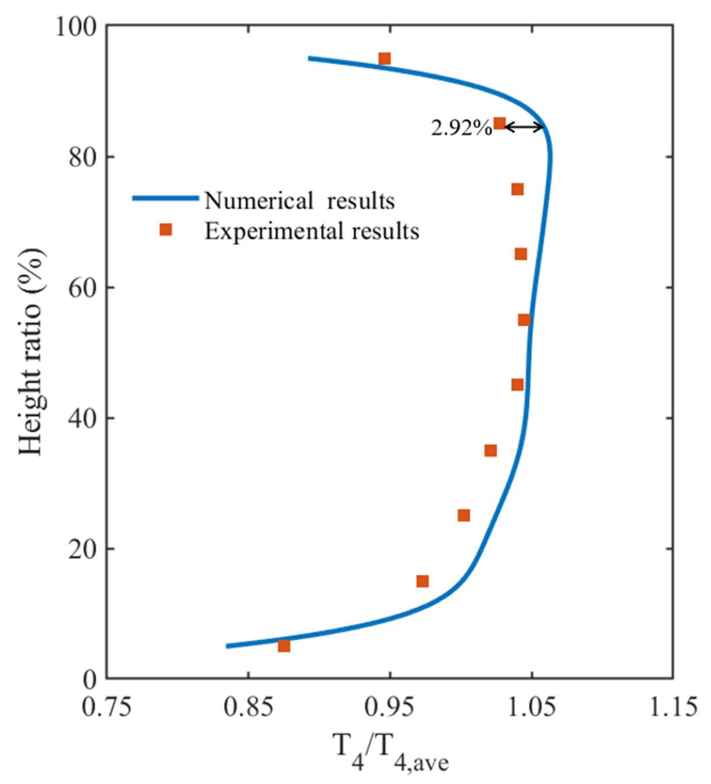
The numerical results obtained using the above method under the high operating condition are compared with the experimental results in Figure 5. The numerical and experimental radial distributions of outlet temperature show consistent trends, and the maximum circumferentially averaged temperature error is only 2.92%. The error mainly arises from measurement uncertainty, unsteady fluctuations in the outlet temperature field, and simplifications in the numerical treatment of turbulent combustion and wall heat transfer. Overall, the maximum error of 2.92% is within the acceptable range for engineering combustor simulations, and the numerical results reproduce the experimental outlet temperature distribution well. These results demonstrate that the numerical method adopted in this study has good predictive accuracy and reliability.
Figure 5.
Comparison of Radial Temperature Distributions at the Outlet Between Simulation Calculations and Experimental Validation.
3. Results and Discussion
3.1. Flow-Field Analysis
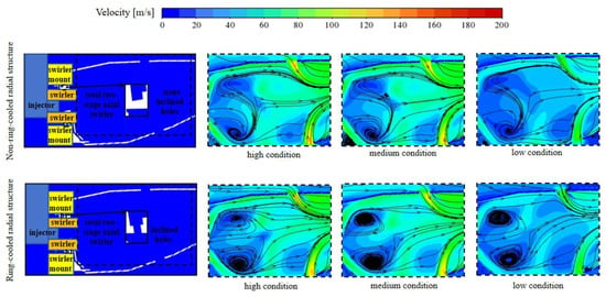
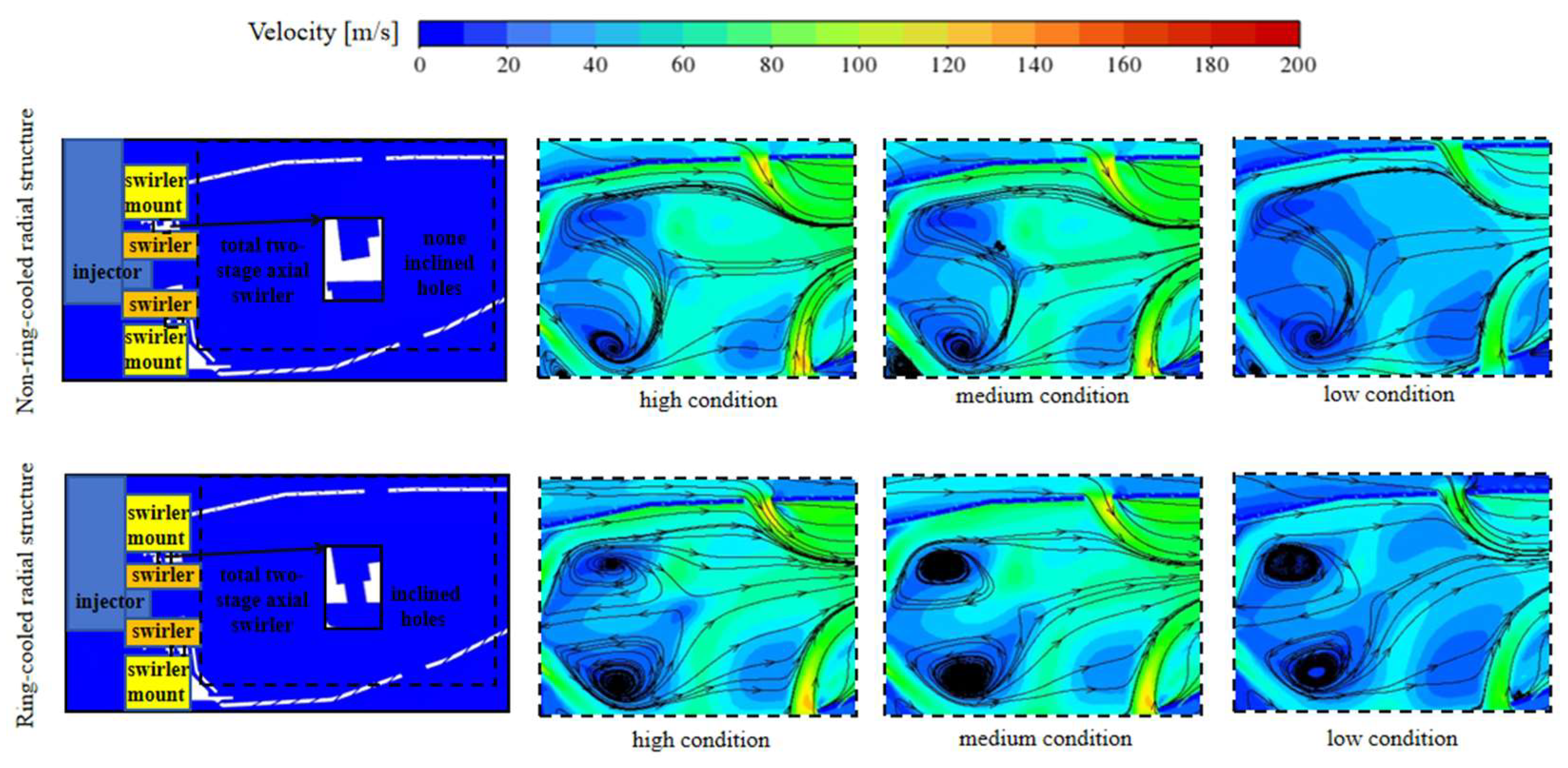
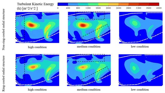
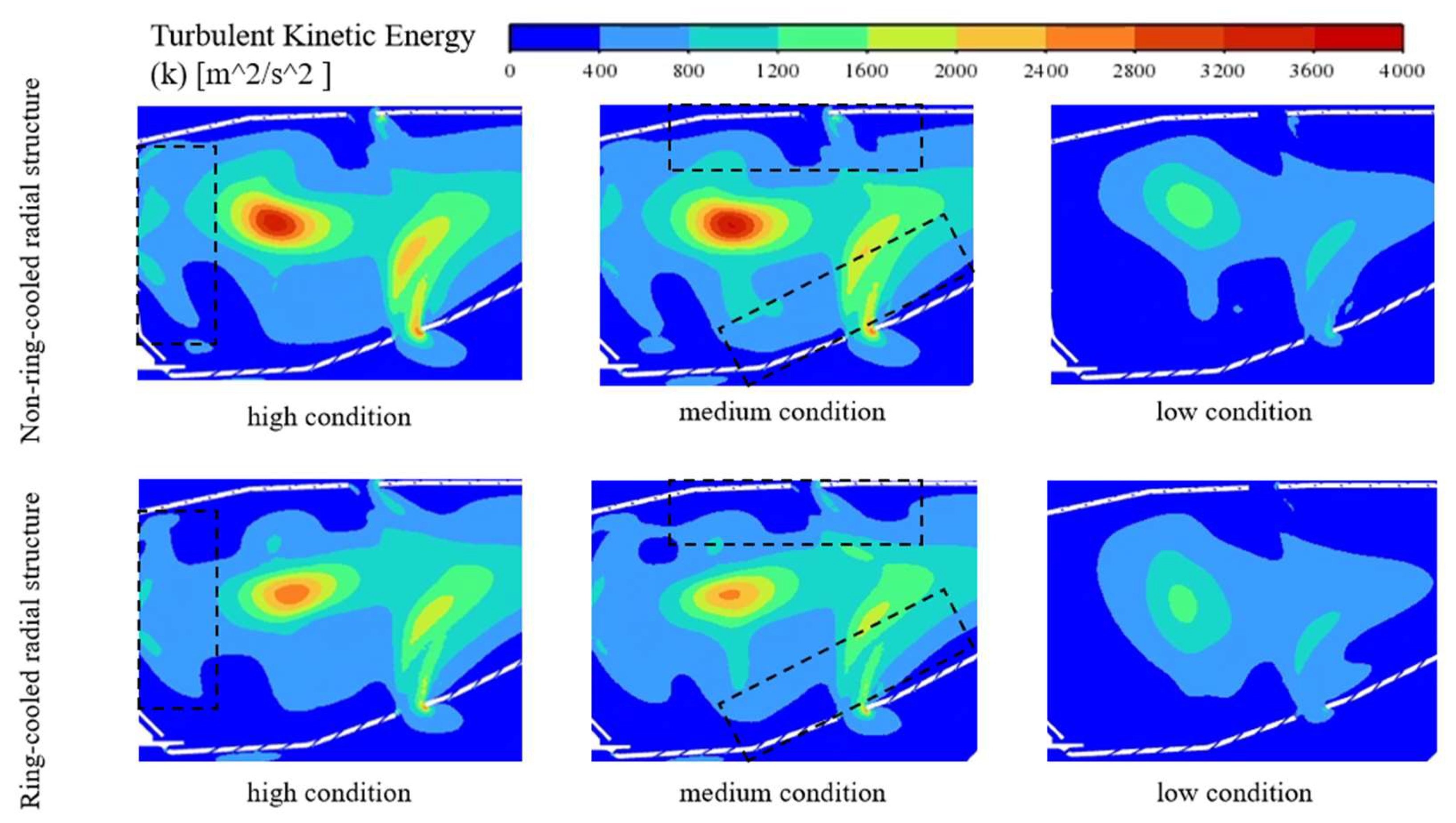
Figure 6 and Figure 7 show the center-plane velocity fields and turbulent kinetic energy distributions of the combustor with and without the ring-cooled radial structure under high, medium, and low operating conditions. In the non-ring-cooled configuration, a large primary recirculation vortex is formed in the core reaction zone. This recirculation structure increases the residence time of reactants in the primary zone and is beneficial for flame stabilization. With the ring-cooled radial structure, the third-stage swirl acts from the outer side on the main flow produced by the first two axial swirlers. As a result, the head-end recirculation zone evolves from a single large-scale vortex into multiple vortical structures, and the flow symmetry is significantly improved. The multiple recirculation vortices enhance entrainment and recirculation mixing near the nozzle, promote contact among fuel vapor, main airflow, and high-temperature recirculated products, and improve mixing uniformity and flame stability in the front primary zone.
Figure 6.
Velocity field on the combustor central section.
Figure 7.
Turbulent kinetic energy distribution on the combustor central section.
The turbulent kinetic energy distribution further reveals the mechanism of the flow-field variation. In the non-ring-cooled configuration, high turbulent kinetic energy is mainly concentrated in the interface between the high-speed swirling jet downstream of the nozzle and the low-speed recirculation zone, as well as in the region influenced by the primary-hole jets. The local peak is relatively high but spatially skewed, indicating strong local velocity gradients and mixing but insufficient flow structure uniformity. With the ring-cooled radial structure, the high-turbulent-kinetic-energy region near the front end becomes more concentrated toward the combustor center and more symmetric. This indicates that the third-stage swirl reshapes the main-flow/recirculation interface formed by the first two axial swirlers and makes the turbulent mixing near the nozzle more uniform. This feature corresponds to the multiple recirculation vortices and more symmetric flow structure observed in the velocity field, demonstrating that the ring-cooled radial structure improves head-end fuel-air mixing and flame anchoring.
The third-stage swirl also modifies the near-wall flow structure. Because the cooling air exits the inclined holes on the mounting seat with a tangential velocity component, it forms a rotating cooling layer between the outer side of the primary zone and the liner near-wall region. The turbulent kinetic energy distribution shows that the near-wall region in the ring-cooled configuration maintains a relatively low turbulent kinetic energy along the axial direction. This indicates that the cooling layer does not mix intensely with the high-temperature main flow and therefore has good continuity and coverage capability. In addition, the third-stage swirl also redistributes the turbulent kinetic energy in the middle and downstream regions of the primary zone. In particular, near the dilution and primary-hole regions, the turbulent kinetic energy peak in the core region is lower in the ring-cooled configuration than in the non-ring-cooled configuration, indicating that the third-stage swirl redistributes the main shear layer and downstream mixing process.
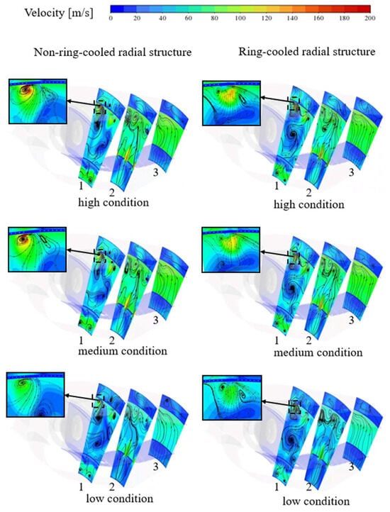
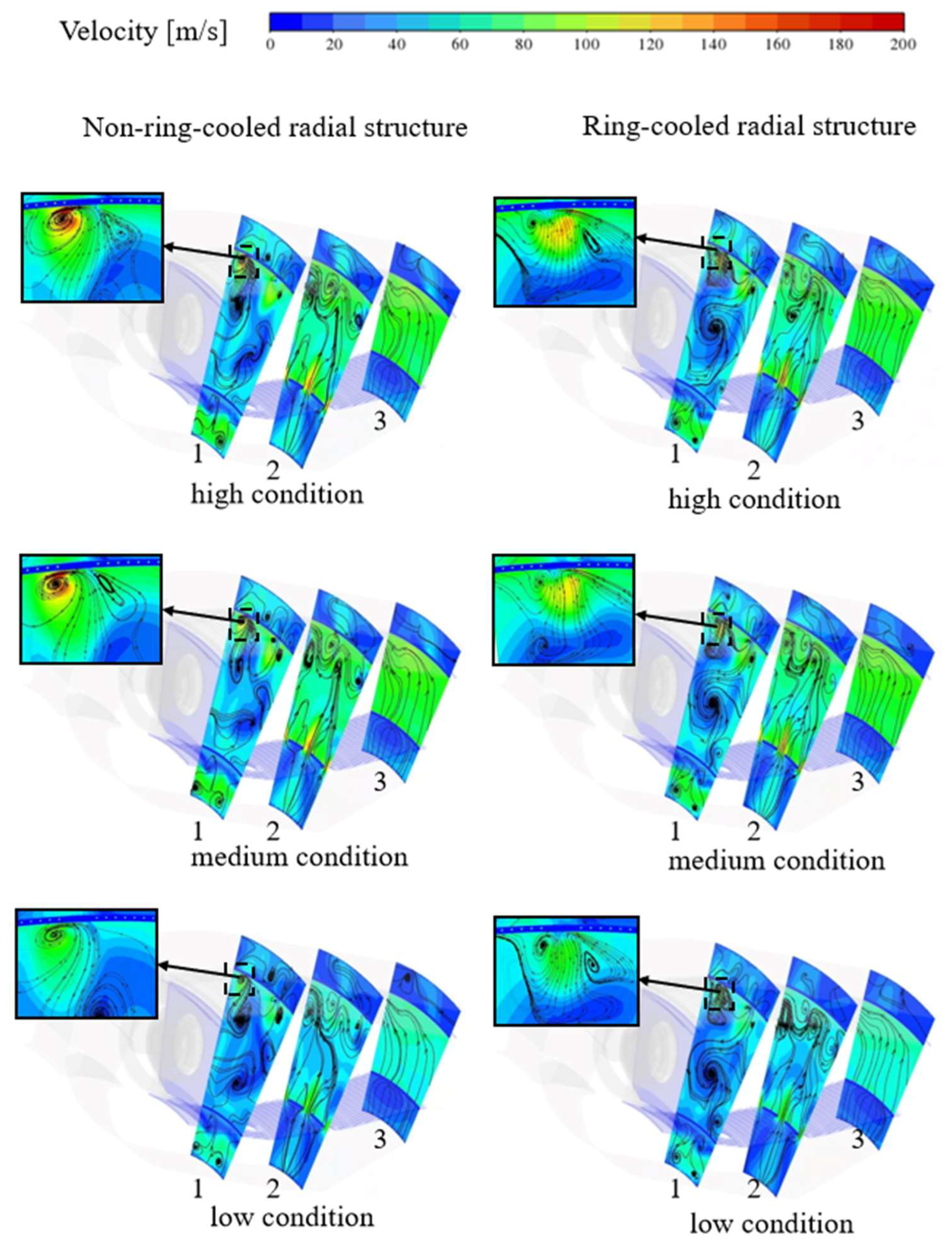
Figure 8 shows the velocity fields on three representative radial sections of the combustors without and with the ring-cooled radial structure under high-, medium-, and low-load conditions, reflecting the evolution of the flow field along the flow direction. Plane 1 is located in the near downstream region of the primary combustion holes, namely the near-injection mixing zone, where fuel-air mixing and flame anchoring are most sensitive to reverse flow. A low-velocity recirculation region exists in this zone and is beneficial for air-fuel mixing. Plane 2 is located in the core reaction zone, where the main heat-release region interacts with high-temperature recirculating flow. Plane 3 is located in the outlet redistribution zone, where the airflow velocity is relatively high, the streamline trajectories are smooth, no obvious mixing is observed, and the flow has been reorganized before entering the downstream turbine passage.
Figure 8.
Flow field on combustor radial sections.
The radial sections show that a relatively strong kidney-shaped vortex pair is readily formed downstream of the primary holes and near the wall in the non-ring-cooled configuration. With the ring-cooled radial structure, cooling air flows out through the inclined holes on the dual axial-swirler mounting seat and forms a third-stage swirl outside the first two axial swirls. This third-stage swirl has a clear circumferential velocity component and is located between the outer edge of the primary zone and the liner near-wall region. On the one hand, it constrains and redistributes the near-wall vortex structure induced by the primary-hole jets, weakening the high-speed reverse-flow region originally developing close to the wall and reducing the entrainment intensity and near-wall sweeping range of the kidney-shaped vortex pair. On the other hand, the low-temperature cooling air forms a circumferential cooling film near the wall and produces a low-speed recirculation layer under the combined effects of main-flow rotation and local adverse pressure gradients. This low-speed recirculation layer lies between the high-temperature main flow and the liner wall, reducing direct contact between the hot gas and the wall and thereby lowering the wall thermal load.
Specifically, on Plane 1, the ring-cooled radial structure reduces the size of the near-wall high-speed reverse-flow region, and the local streamlines change from strong entrainment to a more dispersed recirculation pattern. This indicates that the third-stage swirl weakens the near-wall vortex pair induced by the primary-hole jets. On Plane 2, a distinct recirculating and rotating structure remains in the core region of the ring-cooled configuration, indicating that the recirculation required for primary-zone mixing and flame stabilization is not destroyed.
Under different operating conditions, the combustor flow fields exhibit similar patterns but different intensities. Under the high operating condition, the interaction between the primary-hole jets and the swirling main flow is the strongest; therefore, the kidney-shaped vortex pair and near-wall high-speed reverse-flow region are most pronounced, leading to the strongest wall-sweeping effect. Under the medium condition, the vortex strength and near-wall high-speed region decrease. Under the low condition, the overall flow momentum is lower, and the kidney-shaped vortex pair and its near-wall entrainment effect are relatively weak.
3.2. Temperature-Field Analysis
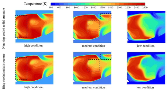
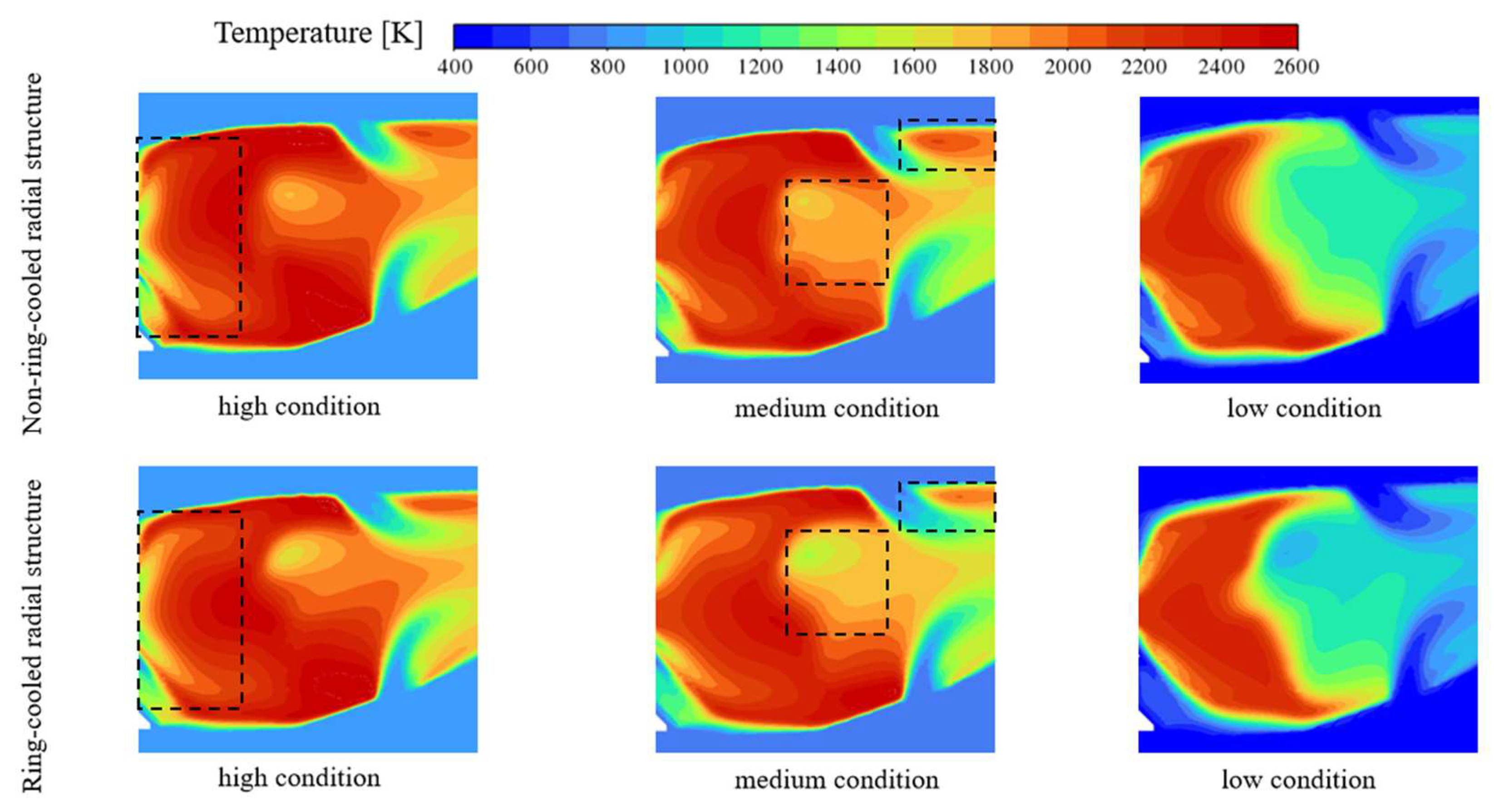
Figure 9 shows the center-plane temperature fields of the combustor with and without the ring-cooled radial structure under high, medium, and low operating conditions. Overall, the red and orange high-temperature regions are mainly concentrated in the middle-right region of the combustor, with temperatures approaching approximately 2000 K. In this region, fuel and air are sufficiently mixed and combust vigorously, releasing a large amount of heat and causing a rapid temperature rise. The blue low-temperature regions are mainly located near the inlet on the left side and along the upper and lower edges, with temperatures in the range of 400–800 K. The left-side inlet corresponds to the region where fresh air and fuel have not yet been fully mixed, while the upper and lower edge regions are affected by cooling air and therefore maintain lower temperatures.
Figure 9.
Temperature field on the combustor central section.
Combining the velocity field and turbulent kinetic energy distribution shows that the ring-cooled radial structure affects the temperature field in a spatially nonuniform manner. In the front region downstream of the nozzle, the third-stage swirl acts from the outer side on the main flow formed by the first two axial swirlers. It increases the number of recirculation vortices, improves flow symmetry, and concentrates the high-turbulent-kinetic-energy region toward the combustor center. This flow structure promotes more uniform fuel-air mixing, and therefore the ring-cooled configuration exhibits enhanced combustion intensity in the front primary zone.
In the middle and downstream regions of the combustor, the ring-cooled radial structure mainly redistributes the primary-zone temperature field. Because the third-stage swirl changes the interface between the core main flow and recirculation region as well as the velocity-gradient distribution, the turbulent kinetic energy peak near the dilution and primary-hole regions is reduced. As a result, local mixing and combustion intensity in this region are slightly weaker than those in the non-ring-cooled configuration. Consequently, parts of the core high-temperature region in the ring-cooled configuration exhibit slightly lower temperature levels and smaller extents than those in the non-ring-cooled configuration, while the overall temperature remains high. This indicates that the ring-cooled radial structure does not simply intensify combustion throughout the entire field; rather, while maintaining sufficient primary-zone combustion, it redistributes the heat-release location and temperature gradients.
The temperature fields under the three operating conditions show similar distributions with slight differences. In terms of high-temperature-region extent, the high operating condition has the largest high-temperature zone and the strongest combustion, followed by the medium and low conditions. Regarding the temperature gradient in the high-temperature region, the gradient is smallest under the high condition, indicating more stable combustion, followed by the medium and low conditions. Near the liner wall, the temperature and temperature gradient are highest under the high condition, indicating the strongest influence on the liner wall, followed by the medium and low conditions.
3.3. Liner Wall-Temperature Analysis
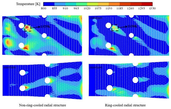
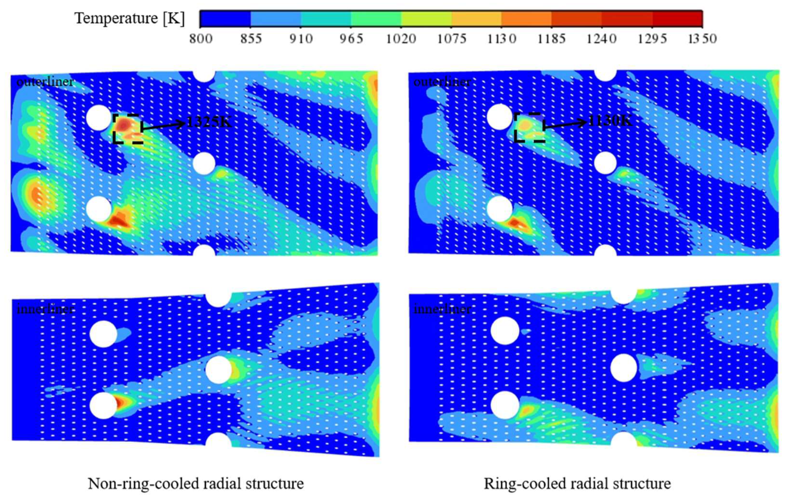
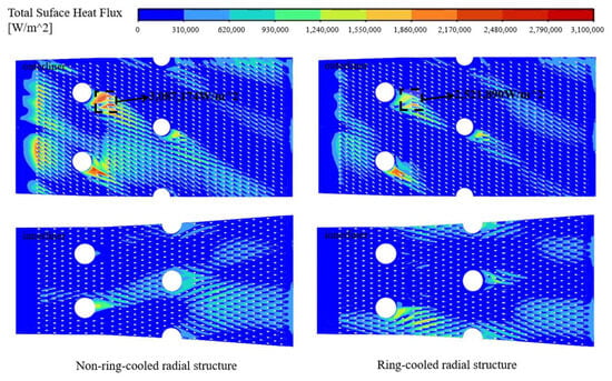
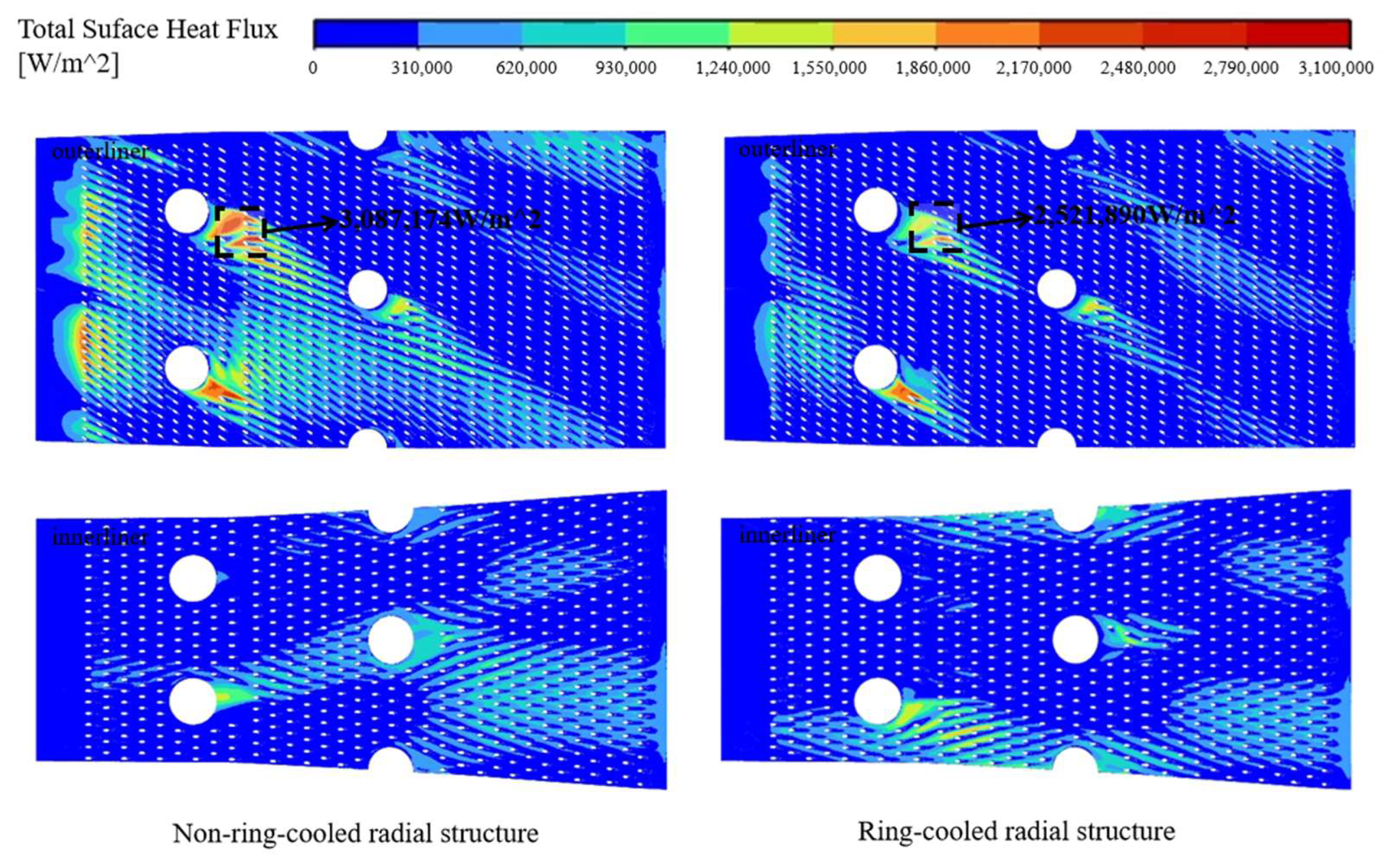
Figure 10 and Figure 11 show the liner wall temperature and total surface heat flux distributions, respectively, for the combustor with and without the ring-cooled radial structure under the high operating condition. Overall, the thermal load on the outer liner is significantly higher than that on the inner liner, and local high-temperature and high-heat-flux regions are mainly concentrated near and downstream of the primary holes. For the non-ring-cooled configuration, obvious hot spots and high-heat-flux peaks appear near the primary holes of the outer liner. The maximum wall temperature reaches 1325 K, the peak total surface heat flux reaches 3.087 × 10⁶ W/m2, and the standard deviation of the outer-liner wall temperature is 63.77 K. Combined with the preceding center-plane and radial-section flow analyses, these results indicate that, in the non-ring-cooled configuration, the head-end recirculation zone and the kidney-shaped vortex pair induced by the primary-hole jets tend to develop toward the near-wall region, causing high-temperature gas to be entrained and swept along the wall. This process increases direct contact between hot gas and the wall and enhances the near-wall velocity and temperature gradients, ultimately leading to concentrated increases in wall temperature, heat flux, and temperature nonuniformity near the primary holes.
Figure 10.
Liner wall temperature.
Figure 11.
Liner wall heat flux.
With the ring-cooled radial structure, the peak temperature of the outer liner decreases from 1325 K to 1130 K, corresponding to a reduction of 14.72%. The peak total surface heat flux decreases from 3.087 × 10⁶ W/m2 to 2.522 × 10⁶ W/m2, corresponding to a reduction of approximately 18.31%. The standard deviation of the outer-liner wall temperature decreases from 63.77 K to 40.80 K, and the wall-temperature uniformity improves by 36.02%. These results indicate that the ring-cooled radial structure not only reduces the wall temperature level and instantaneous thermal loading, but also decreases the wall temperature gradient, thereby helping to reduce thermal stress caused by nonuniform wall-temperature distributions. The reason is that the inclined holes arranged on the dual axial-swirler mounting seat allow the cooling air to form a third-stage swirl outside the first two axial swirls. This swirl modifies the spatial distribution of the head-end recirculation zone and the vortex structures induced by the primary-hole jets, weakening the near-wall entrainment and high-speed sweeping of the kidney-shaped vortex pair. It also forms a low-temperature cooling film and a low-speed near-wall layer between the outer edge of the primary zone and the liner near-wall region, reducing direct contact between the hot gas and the wall.
The wall heat-flux distribution further shows that, with the ring-cooled radial structure, both the area and peak value of the high-heat-flux region near the primary holes decrease. This indicates that the third-stage swirl affects the wall heat-transfer process in two ways. First, the near-wall low-temperature film reduces the gas temperature adjacent to the wall and thus decreases the gas-solid temperature difference. Second, the low-speed near-wall layer weakens direct impingement of the high-temperature main flow on the wall and reduces the local convective heat-transfer enhancement caused by high-speed reverse flow and vortex-pair sweeping near the primary holes. Meanwhile, the reduced high-heat-flux region weakens local hot spots and makes the wall temperature distribution more uniform, further explaining the significant decrease in the standard deviation of the outer-liner wall temperature.
3.4. Outlet Temperature-Distribution Analysis
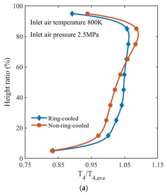
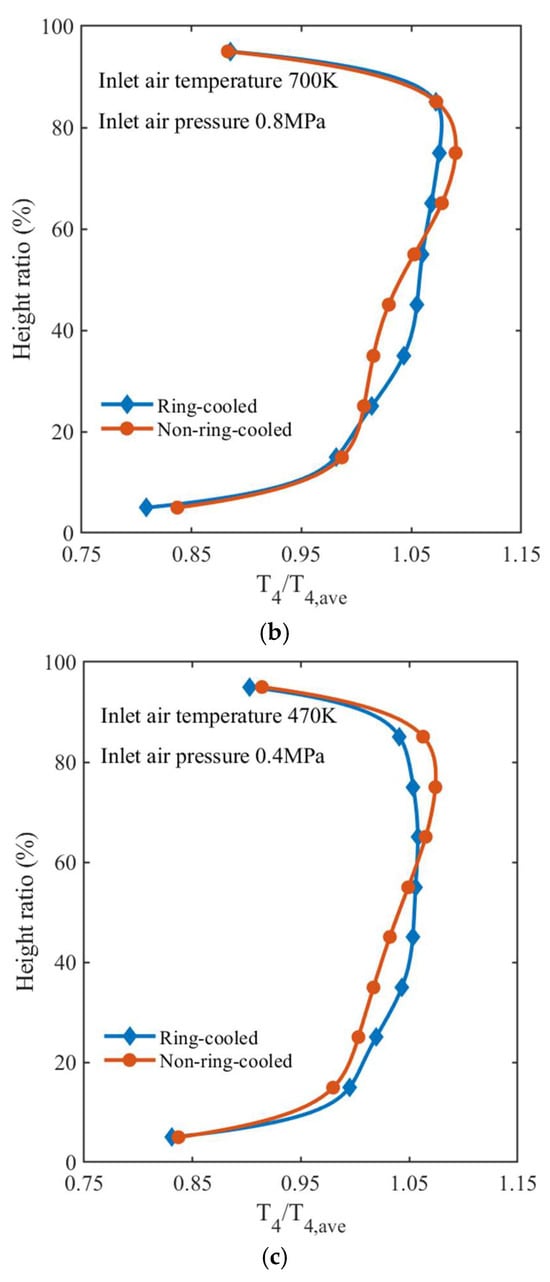
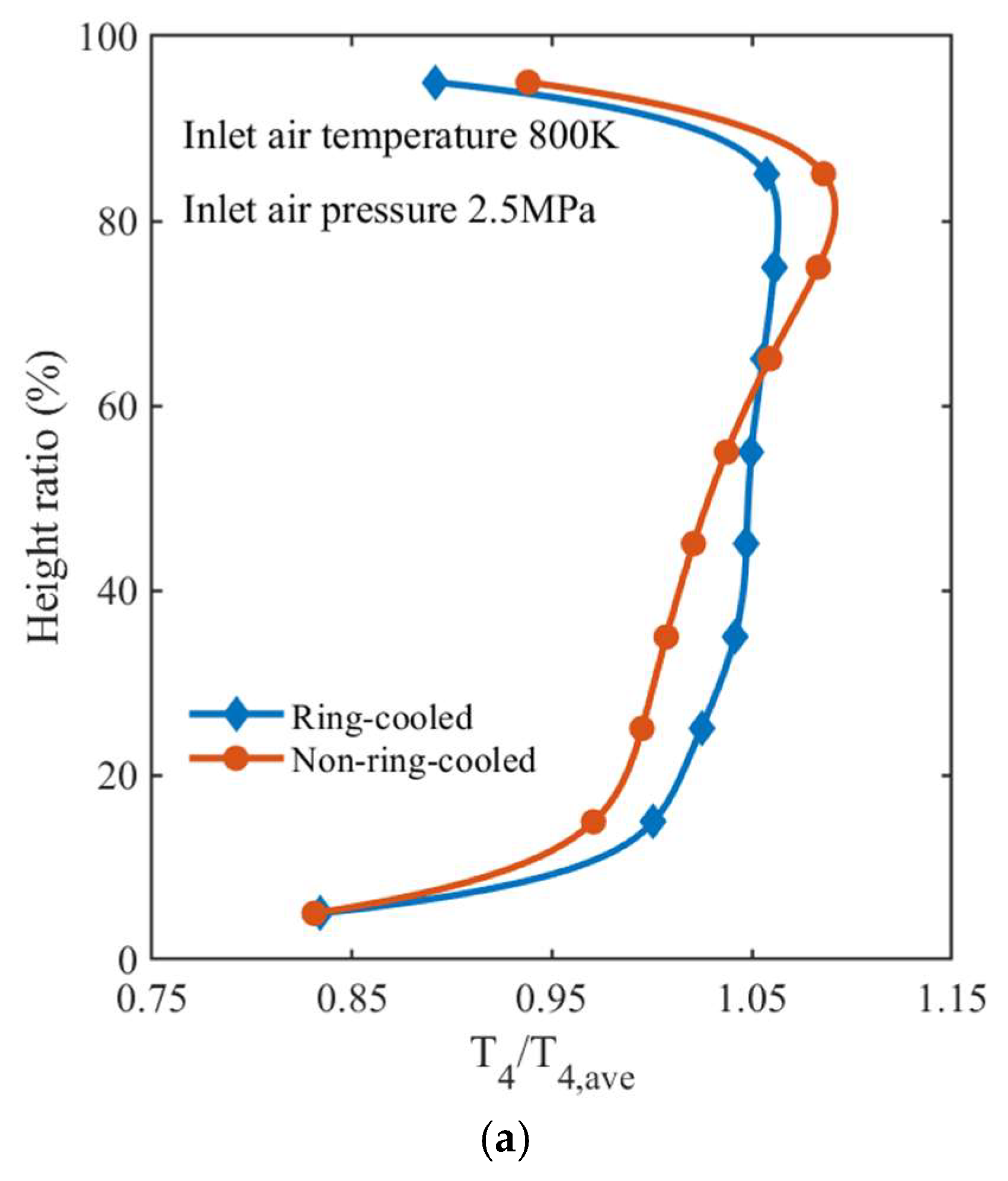
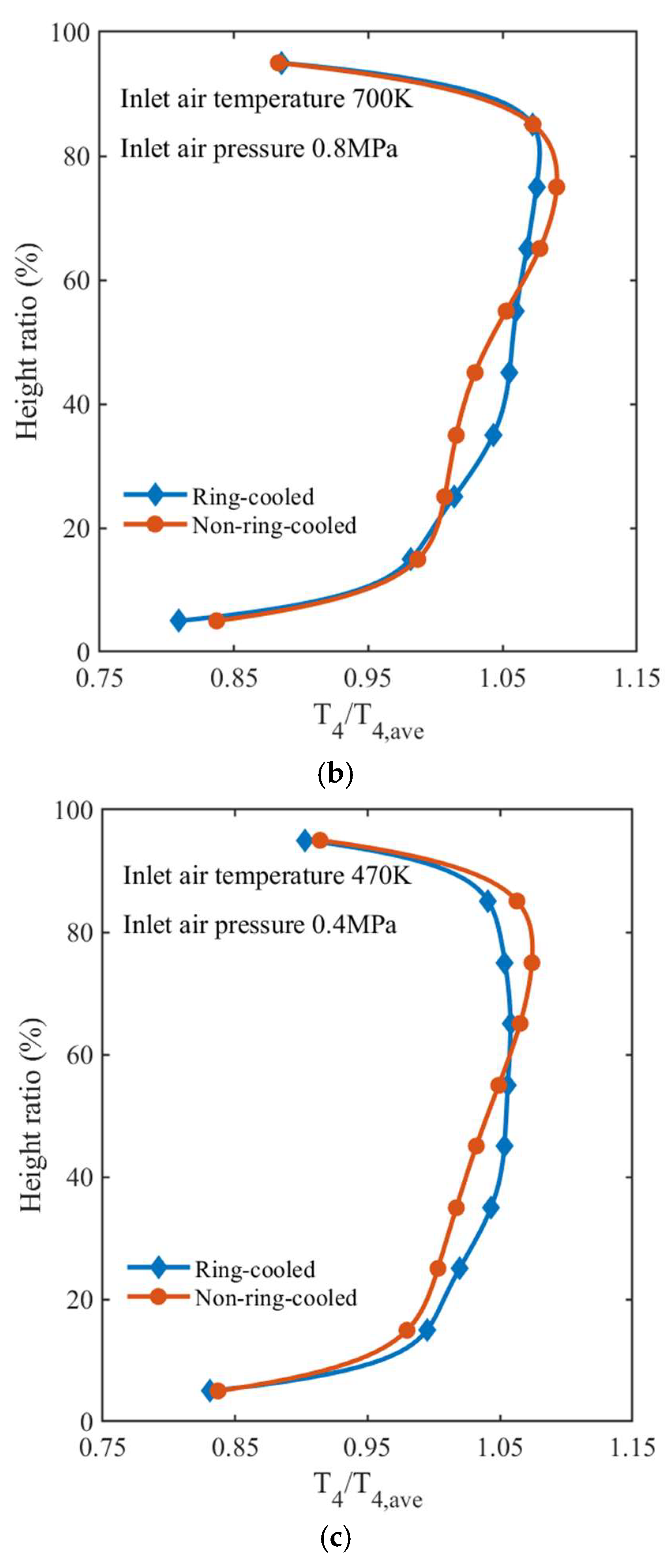
Figure 12 shows the radial outlet temperature distributions of the combustor with and without the ring-cooled radial structure under high, medium, and low operating conditions. For all operating conditions, the outlet temperature of both configurations is higher in the middle region and lower near the two ends. With the ring-cooled radial structure, the outlet temperature curve becomes smoother, the local maximum temperature decreases, and the radial temperature gradient is reduced, indicating improved outlet temperature uniformity.
Figure 12.
Combustor outlet temperature distribution: (a) high condition; (b) medium condition; (c) low condition.
It is noteworthy that the effect of the ring-cooled radial structure varies with height at the outlet plane. In the upper region, corresponding to a height ratio of approximately 60–90%, T4/T4,ave is lower in the ring-cooled configuration than in the non-ring-cooled configuration, indicating a reduction in gas temperature in this region. This is mainly associated with the low-temperature cooling coverage formed by the third-stage swirl outside the primary zone. After the cooling air enters through the inclined holes, it forms a rotating cooling layer outside the primary zone and weakens the entrainment and sweeping of high-temperature near-wall gas, thereby cooling and diluting the hot gas near the outer wall in the upper region and reducing the outlet temperature there.
In contrast, in the middle-lower region, corresponding to a height ratio of approximately 20–55%, T4/T4,ave in the ring-cooled configuration is slightly higher than that in the non-ring-cooled configuration. This does not imply an increase in the overall combustion temperature. Rather, the ring-cooled radial structure changes the primary-zone recirculation structure and transport path of high-temperature products, causing hot gas originally concentrated in the upper region to be redistributed toward the middle-lower region of the outlet plane. Therefore, the outlet temperature distribution exhibits a redistribution pattern in which the upper-region temperature decreases while the middle-lower-region temperature increases moderately.
Table 3 lists the outlet temperature distribution factor (OTDF) of combustors without and with the ring-cooled radial structure under high-, medium-, and low-load conditions. The calculation formula is given in Equation (6).
where T3,ave is the average combustor inlet temperature, T4,ave is the average outlet temperature, and T4,max is the maximum temperature on the outlet plane.
Table 3.
Combustor outlet OTDF.
As shown in Table 3, the improvement in OTDF due to the ring-cooled radial structure is strongly dependent on the operating condition. Under the high operating condition, the OTDF decreases from 0.27 to 0.23, corresponding to a reduction of 14.81%. Under the medium operating condition, the improvement is more pronounced, with the OTDF decreasing from 0.38 to 0.32, corresponding to a reduction of 15.79%.
According to the OTDF definition, its decrease is mainly determined by the reduction in the difference between the global maximum outlet-plane temperature T4,max and the average outlet temperature T4,ave. The preceding temperature-field analysis shows that both configurations maintain a high combustion level in the primary zone, indicating that their overall combustion intensity and average outlet temperature differ only slightly. Therefore, the reduction in OTDF caused by the ring-cooled radial structure is not primarily due to a significant decrease in the average outlet temperature. Instead, the third-stage swirl improves the primary-zone flow structure and near-wall cooling coverage, weakens local high-temperature hot spots at the outlet, reduces T4,max, and consequently decreases the OTDF.
Under the low operating condition, however, the OTDF of both configurations is 0.20. This is because the overall heat-release level is low, the outlet temperature field is already relatively uniform, and the difference between the local maximum temperature and the average temperature is small. As a result, the ring-cooled radial structure provides limited further improvement in OTDF.
4. Conclusions
This study investigates the flow and combustion characteristics of a novel triple-swirler combustor under multiple operating conditions using the Realizable k−ε turbulence model and the finite-rate/eddy-dissipation combustion model. The main conclusions are as follows:
- Cooling air issued through the inclined holes on the dual-axial-swirler mounting seat generates a third-stage swirl, which regulates the recirculation structure formed by the first two axial swirlers from the outer side. As a result, the core reaction zone evolves from a single large-scale recirculation vortex into multiple vortical structures, with improved flow symmetry and a more centrally concentrated high-turbulent-kinetic-energy region near the combustor head, thereby enhancing fuel-air mixing and flame stabilization in the head region.
- The third-stage swirl forms a low-temperature cooling coverage outside the primary zone and weakens the near-wall entrainment and high-speed sweeping induced by the kidney-shaped vortex pair downstream of the primary holes. This reduces direct contact between high-temperature near-wall gas and the liner wall. Meanwhile, without disrupting the recirculation mixing required in the core reaction zone, the ring-cooled structure redistributes the heat-release location and temperature gradients in the primary zone.
- Compared with the combustor without the ring-cooled radial structure, the novel triple-swirler combustor has a lower overall liner wall temperature and a smaller temperature gradient in the high-temperature region. The peak wall temperature decreases to 1130 K, representing a reduction of 14.72%, and the temperature uniformity increases by 36.02%.
- The uniformity of the radial outlet-temperature distribution is significantly improved, and the OTDF is substantially reduced. Under the high-load condition, the OTDF decreases to 0.23, an improvement of 14.81%; under the medium-load condition, it decreases to 0.32, an improvement of 15.79%.
Author Contributions
Conceptualization, R.C.; validation, Y.Z. and W.Z.; formal analysis, C.W.; writing—original draft preparation, C.W.; writing—review and editing, R.C., W.L., Q.Z., Y.Z. and W.Z.; supervision, Q.Z.; project administration, W.L.; funding acquisition, Q.Z. All authors have read and agreed to the published version of the manuscript.
Funding
This research was supported by the Science Center for Gas Turbine Project of China (Grant No. 2022-A-II-005).
Data Availability Statement
The data presented in this study are available on request from the corresponding author due to institutional confidentiality restrictions and the sensitive nature of the research data.
Conflicts of Interest
The authors declare no conflict of interest.
References
- Meng, L.Y.; Gao, H.H.; Zheng, T.H.; Guo, Q. Study on technical indexes of thrust-to-weight ratio of aero-engines. Gas Turbine Exp. Res. 2016, 29, 57–62. [Google Scholar]
- Chin, J. Suggestions on High Temperature Rise Combustor. In Proceedings of the AIAA Propulsion and Energy 2019 Forum, Indianapolis, IN, USA, 19–22 August 2019. [Google Scholar]
- Liu, Y.; Sun, X.; Sethi, V.; Nalianda, D.; Li, Y.G.; Wang, L. Review of modern low emissions combustion technologies for aero gas turbine engines. Prog. Aerosp. Sci. 2021, 94, 12–45. [Google Scholar]
- Jin, R.S.; Suo, J.Q. Advanced Gas Turbine Combustors; Aviation Industry Press: Beijing, China, 2016; pp. 6–7. [Google Scholar]
- Chin, J.; Dang, J. New Generation Aero Combustor. In Renewable Energy-Technologies and Applications; IntechOpen: London, UK, 2021. [Google Scholar] [CrossRef] [Scilit]
- Zeng, Q.; Chen, X. Combustor technology of high temperature rise for aero engine. Prog. Aerosp. Sci. 2023, 140, 100927. [Google Scholar] [CrossRef] [Scilit]
- Mehta, P.R.; Patil, K.M.; Parab, S.R.; Patel, P.R.; Kale, R.V. Design and CFD simulation of triple swirler in jet engine. AIP Conf. Proc. 2022, 2421, 060006. [Google Scholar] [CrossRef] [Scilit]
- Xu, L.; Liu, K. Experiment of combustion characteristic of triple swirler combustor. J. Aerosp. Power 2018, 33, 2067–2073. [Google Scholar] [CrossRef]
- Zhou, T.; Zhao, K.; Li, F.; Wang, K.; Meng, N.; Wang, D. Effects of swirl numbers on the unsteady characteristics of pilot flame in a triple-swirler staged combustor. Case Stud. Therm. Eng. 2023, 44, 102846. [Google Scholar] [CrossRef] [Scilit]
- Jiang, B.; Zhao, Z.Q.; He, X.M.; Ding, G.Y.; Li, M.Y. Effect of inner-swirler swirl number on the flow-field characteristics of a three-stage swirling flow. J. Propuls. Technol. 2016, 37, 2150–2156. [Google Scholar] [CrossRef]
- Cheng, R.H.; Zhang, Z.S.; Ruan, W.B.; Wang, J. Core key technologies of advanced aircraft engine. Acta Aeronaut. Astronaut. Sin. 2025, 46, 31220. [Google Scholar] [CrossRef]
- Ali, A.B.S.; Kriaa, W.; Mhiri, H.; Bournot, P. Analysis of the influence of cooling hole arrangement on the protection of a gas turbine combustor liner. Meccanica 2018, 53, 2257–2271. [Google Scholar] [CrossRef] [Scilit]
- Ji, Y.; Ge, B.; Chi, Z.; Zang, S. Overall cooling effectiveness of effusion cooled annular combustor liner at reacting flow conditions. Appl. Therm. Eng. 2018, 130, 877–888. [Google Scholar] [CrossRef] [Scilit]
- Jackowski, T.; Elfner, M.; Bauer, H.-J. Experimental study of impingement effusion-cooled double-wall combustor liners: Thermal analysis. Energies 2021, 14, 4843. [Google Scholar] [CrossRef] [Scilit]
- Ji, Y.; Ge, B.; Zang, S. Conjugate heat transfer characteristics of effusion cooling under realistic swirl flow in a three-sector gas turbine model combustor. Appl. Therm. Eng. 2022, 213, 118735. [Google Scholar] [CrossRef] [Scilit]
- Zhang, Y.; Li, J.; Xie, J. Effects of lateral cooling hole configuration on a swirl-stabilized combustor. Energy 2022, 259, 125002. [Google Scholar] [CrossRef] [Scilit]
- Chen, X.; Cheng, R.; Zeng, Q.; Li, W.; Zhang, X.; Zhao, Y. Characteristic scale identification of recirculation zone and outlet distribution regulation for a novel triple-swirler combustor. Aerosp. Sci. Technol. 2026, 177, 112988. [Google Scholar] [CrossRef] [Scilit]
- AECC Sichuan Gas Turbine Research Institute. A Triple-Swirler Liner Head Design Method for Controlling Combustor Vortex-Core Scale. 202311010044.8[P]. 16 January 2024. (In Chinese)
- Shih, T.-H.; Liou, W.W.; Shabbir, A.; Yang, Z.; Zhu, J. A new k-ε eddy viscosity model for high Reynolds number turbulent flows. Comput. Fluids 1995, 24, 227–238. [Google Scholar] [CrossRef] [Scilit]
- Kumar, A.; Bharti, R.P. Assessment of RANS-based turbulence models for isothermal confined swirling flow in a realistic can-type gas turbine combustor application. J. Comput. Sci. 2024, 81, 102362. [Google Scholar] [CrossRef] [Scilit]
- Chen, X.; Zeng, Q.; Li, B.; Wang, C.; Xie, P. Numerical study of ammonia/n-dodecane combustion and emission characteristics in a micro gas turbine combustor. Fuel 2026, 405, 136729. [Google Scholar] [CrossRef] [Scilit]
- Chen, X.; Yang, H.; Zeng, Q.; Zheng, M.; Li, W.; Xie, P. Multi-objective optimization of axially graded compound-angled effusion cooling for combustor liner based on AM-RSM and NSGA-II. Appl. Therm. Eng. 2025, 279, 128020. [Google Scholar] [CrossRef] [Scilit]
- Chen, X.; Gui, T.; Zeng, Q.; Tang, J.; Xie, P. Cooling Design and Optimization of a Novel Swirl-Stabilized Trapped Vortex Combustor with Compound-Angled Effusion Cooling Configuration. Appl. Therm. Eng. 2025, 274, 126746. [Google Scholar] [CrossRef] [Scilit]
- Magnussen, B.F.; Hjertager, B.H. On mathematical modeling of turbulent combustion with special emphasis on soot formation and combustion. Symp. (Int.) Combust. 1977, 16, 719–729. [Google Scholar] [CrossRef] [Scilit]
- Dagaut, P.; Cathonnet, M. The ignition, oxidation, and combustion of kerosene: A review of experimental and kinetic modeling. Prog. Energy Combust. Sci. 2006, 32, 48–92. [Google Scholar] [CrossRef] [Scilit]
- Westbrook, C.K.; Dryer, F.L. Simplified reaction mechanisms for the oxidation of hydrocarbon fuels in flames. Combust. Sci. Technol. 1981, 27, 31–43. [Google Scholar] [CrossRef] [Scilit]
- De, A.; Oldenhof, E.; Sathiah, P.; Roekaerts, D. Numerical simulation of Delft-jet-in-hot-coflow (DJHC) flames using the Eddy Dissipation Concept model for turbulence–chemistry interaction. Flow Turbul. Combust. 2011, 87, 537–567. [Google Scholar] [CrossRef] [Scilit]
- Grosshans, H.; Cao, L.; Fuchs, L.; Szász, R.Z. Computational sensitivity study of spray dispersion and mixing on the fuel properties in a gas turbine combustor. Int. J. Heat Fluid Flow 2016, 61, 123–133. [Google Scholar]
- Salewski, M.; Duwig, C.; Milosavljevic, V.; Fuchs, L. Large Eddy Simulation of Spray Combustion in a Swirl-Stabilized Gas Turbine Burner. In Proceedings of the 43rd AIAA/ASME/SAE/ASEE Joint Propulsion Conference & Exhibit, Cincinnati, OH, USA, 8–11 July 2007. [Google Scholar]
- Amerini, A.; Facchini, B.; Mazzoni, S. Computational Optimization of a Loosely-Coupled Strategy for Scale-Resolving CHT CFD Simulation of Gas Turbine Combustors. Energies 2023, 16, 1664. [Google Scholar] [CrossRef] [Scilit]

Disclaimer/Publisher’s Note: The statements, opinions and data contained in all publications are solely those of the individual author(s) and contributor(s) and not of MDPI and/or the editor(s). MDPI and/or the editor(s) disclaim responsibility for any injury to people or property resulting from any ideas, methods, instructions or products referred to in the content. |
© 2026 by the authors. Licensee MDPI, Basel, Switzerland. This article is an open access article distributed under the terms and conditions of the Creative Commons Attribution (CC BY) license.