


Abstract
To overcome the limitation of conventional nose landing gear shimmy damper design, which is mainly based on the critical damping for torsional shimmy while neglecting the high-damping-side instability boundary, this study establishes a nonlinear shimmy dynamic model of a nose landing gear equipped with a hydraulic damper and an inerter-based suppression system. Hopf bifurcation analysis, numerical continuation, and energy-evolution analysis are employed to investigate the effects of damper, structural, and inerter parameters on the zero-shimmy region over the full speed range. The results show that the zero-shimmy damping interval is not governed by a single torsional critical damping value but is jointly bounded by the tire-induced torsional shimmy boundary on the low-damping side and the lateral or structural torsional shimmy boundary on the high-damping side. Thus, increasing damper damping is not always beneficial. Among the structural parameters, trail determines the existence of the zero-shimmy region, strut torsional stiffness mainly regulates the high-damping-side boundary, and rake angle provides local correction. With proper inertance and tuning-stiffness matching, the inerter-based system raises the upper critical damping by about 210% and improves low-speed shimmy suppression by transferring vibration energy to the damping branch through inertial coupling.
1. Introduction
Landing gear shimmy is a typical self-excited vibration phenomenon during aircraft ground taxiing, usually manifested as coupled vibration between the torsional motion of the wheel about the strut axis and the lateral bending motion of the strut [1]. Shimmy reduces ground handling stability, aggravates tire wear and landing gear structural fatigue damage, and, in severe cases, may affect takeoff and landing safety. Therefore, accurate identification of shimmy instability boundaries within the taxiing speed range and determination of a reliable zero-shimmy parameter region are important issues in nose landing gear dynamic design and shimmy suppression system parameter design.
In engineering practice, hydraulic shimmy dampers are commonly used to suppress shimmy; their basic function is to attenuate torsional vibration energy through damping dissipation. Conventional design is often based on the critical damping for torsional shimmy, with a safety factor introduced to determine the damping parameter. This approach improves torsional stability under low-damping conditions, but it does not sufficiently account for the restriction imposed on the damping upper limit by lateral shimmy or structural torsional shimmy under high-damping conditions. When the shimmy damper damping is excessive, the shimmy damper may alter the phase relation, energy distribution, and modal coupling characteristics between the torsional and lateral degrees of freedom, thereby inducing new high-damping instability. Therefore, shimmy-stability design of a nose landing gear over the full speed range considered in this study (0–200 m/s) should not focus only on the low-damping-side torsional shimmy boundary; it should also identify the high-damping-side boundary governed by lateral shimmy or structural torsional shimmy.
Extensive work has been carried out on landing gear shimmy modeling and stability analysis from the perspectives of tire nonlinearity, structural geometric coupling, multi-degree-of-freedom effects, and airframe flexibility. Thota et al. [2] established a nonlinear dual-wheel nose landing gear model, including torsional and lateral bending degrees of freedom, and analyzed the effects of taxiing speed and vertical load on shimmy stability. Gao et al. [3] considered the influence of shock–strut compression on structural stiffness and investigated the effect of multi-degree-of-freedom coupling on the shimmy region. Romero et al. [4] and Jiang et al. [5] analyzed the effects of side-stay attachment angle and shimmy damper joint clearance on shimmy stability boundaries and limit-cycle responses, respectively. Xiao et al. [6] and Ruan et al. [7,8] further considered factors such as strut axial displacement, longitudinal bending, Coulomb friction, structural clearance, and airframe flexibility and showed that boundary conditions and structural flexibility can significantly change the shimmy instability region. Sivakumar et al. [9] established a full-aircraft shimmy model for an unmanned aircraft and showed that whole-aircraft motion coupling affects the local shimmy characteristics of the landing gear. These studies indicate that landing gear shimmy is essentially a nonlinear instability problem under multi-degree-of-freedom and multi-parameter coupling and that a single critical speed or single modal criterion cannot fully describe its stability boundary.
With respect to analysis methods, bifurcation theory, numerical continuation, center-manifold theory, the method of multiple scales, and the complex averaging method have been widely used in shimmy-stability studies [10,11,12,13,14,15,16,17,18,19,20,21,22]. Hopf bifurcation analysis can directly track changes in equilibrium stability and identify shimmy instability boundaries. Compared with time-domain parameter sweeping, numerical continuation is more suitable for continuously tracking bifurcation curves over a wide parameter range. Center-manifold theory can be used for dynamic order reduction and bifurcation-type identification near critical points, whereas analytical methods such as multiple scales and complex averaging can reveal the relations among nonlinear response amplitude, frequency, and stability boundary.
For shimmy suppression, existing studies have mainly focused on hydraulic shimmy damper optimization and new shimmy suppression designs. Hong et al. [23] pointed out that excessive damping may induce shimmy instability. Tamer et al. [24] studied the effects of nonlinear damping and friction on shimmy stability based on Lyapunov-exponent sensitivity. Electromagnetic dampers, magnetorheological dampers, nonlinear energy sinks, and inerters have also been used to improve the adjustability and wide speed range adaptability of shimmy suppression systems [25,26,27,28,29,30,31,32,33,34,35]. Among them, the inerter can generate an inertial force through relative acceleration and regulate system dynamic characteristics without directly increasing static stiffness, showing potential in shimmy suppression and ground-resonance control. However, the regulation law and energy mechanism of the inerter in the zero-shimmy region over the full speed range of a nose landing gear still require further clarification. Practical engineering application requires further consideration of installation space, additional mass, maintenance requirements, and integration with the existing landing gear architecture. The inerter branch should preferably be arranged near the existing shimmy damper, torque links, or strut connection points, while avoiding interference with the steering mechanism, wheel clearance, ground clearance, and retraction path. Meanwhile, the additional mass introduced by the transmission mechanism, housing, brackets, and connecting components may affect local structural modes, retraction mechanism loads, and fatigue life. In addition, issues such as friction, clearance, wear, temperature rise, and seal aging in practical inerters also need to be evaluated through maintenance strategies and functional testing [36,37,38,39,40]. These factors not only affect the practical shimmy suppression performance of the inerter-based shimmy suppression system, but may also further influence the structural reliability, retraction safety, steering function, and long-term service stability of the landing gear. Therefore, they must be regarded as important aspects of safety and airworthiness assessment in aircraft engineering applications.
Based on the above issues, this paper takes a single-wheel nose landing gear as the object of study and establishes a nonlinear shimmy dynamic model with a shimmy damper. Hopf bifurcation analysis and numerical continuation are used to investigate the effects of shimmy damper damping, shimmy damper stiffness, and key structural parameters on the zero-shimmy region over the full speed range. On this basis, an inerter is introduced to construct an inerter-based shimmy suppression system, the effect of inerter parameters on the expansion of the stability region is analyzed, and the wide speed range shimmy suppression mechanism is explained from the perspective of energy evolution.
Through the above study, a dual-boundary interpretation framework for the zero-shimmy region over the full speed range is established. The dominant physical sources of the low-damping-side and high-damping-side boundaries are distinguished, the regulating effects of structural parameters on the dual boundaries are revealed, and the expansion mechanism of the stability region by the inerter-based shimmy suppression branch is further clarified.
2. Nonlinear Shimmy Model of the Nose Landing Gear
Nose landing gear shimmy is jointly formed by tire lateral deformation, strut torsion, strut lateral bending, and energy dissipation in the shimmy damper. To analyze shimmy instability boundaries over the full speed range, a nonlinear dynamic model of a single-wheel nose landing gear is established, including strut torsion, strut lateral bending, tire lateral deformation, and the dynamic response of the shimmy damper. The model assumptions are as follows: airframe elastic deformation, strut axial deformation, and longitudinal bending are neglected; hydraulic fluid compressibility and joint clearance of the shimmy damper are neglected; and tire forces are described using a nonlinear model capable of representing saturation at large slip angles.
2.1. Physical Model and Coordinate Definition
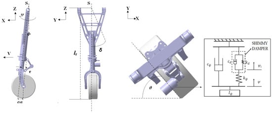
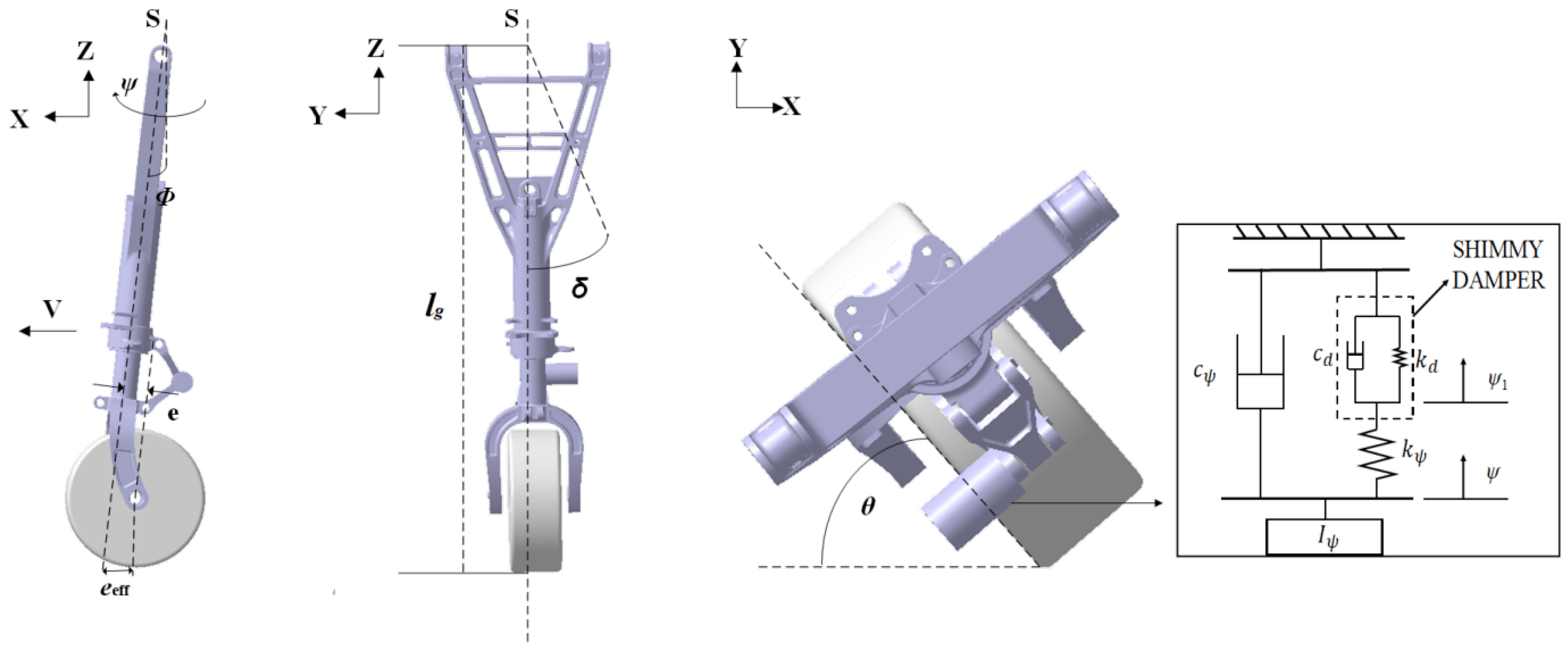
A single-wheel nose landing gear is selected as the research object. A ground coordinate system O-XYZ is established, in which the X-axis is parallel and opposite to the aircraft’s taxiing direction, the Z-axis is vertically upward, and the Y-axis is determined by the right-hand rule. The angle between the landing gear strut centerline and the aircraft’s vertical direction is defined as the strut rake angle , and the landing gear physical model is shown in Figure 1. The shimmy damper is installed in series between the upper and lower torque links of the landing gear. In the dynamic model, its characteristics are equivalently represented by a spring-damper oscillator composed of a linear stiffness and a linear damping in parallel. The main system parameters include the strut length , mechanical trail e, wheel radius R, vertical load , strut torsional angle , strut lateral bending angle , and shimmy damper angular displacement .
Figure 1.
Shimmy model of the nose landing gear.
Owing to the strut rake angle, the kinematic coupling relation between the wheel steering angle and the torsional angle can be expressed as . Meanwhile, the rake angle changes the position of the tire contact point relative to the strut rotation axis, forming the effective trail:
The effective trail directly affects the moment generated by the tire’s lateral force about the strut rotation axis and is an important geometric parameter governing the shimmy stability boundary.
2.2. Nonlinear Dynamic Equations
To describe the coupling among strut torsion, lateral bending, tire lateral deformation, and shimmy damper dynamic response, the system state variables are defined as
The dynamic equations are established using Lagrange equations of the second kind:
The system’s kinetic energy is mainly composed of strut torsional motion and lateral bending motion. The potential energy includes strut torsional strain energy, strut lateral bending strain energy, and the equivalent elastic potential energy of the shimmy damper. The Rayleigh dissipation function includes strut torsional damping, strut lateral damping, shimmy damper damping, and the dissipation term related to tire lateral deformation.
The kinetic energy, potential energy, and Rayleigh dissipation function of the system are respectively given by
where and are the equivalent moments of inertia associated with strut torsion and lateral bending, respectively; , , and denote the strut torsional stiffness, strut lateral stiffness, and shimmy damper stiffness, respectively; and , , , and denote the strut torsional damping, strut lateral damping, shimmy damper damping, and tire tread damping coefficient, respectively.
Because the rotational inertia of the shimmy damper is much smaller than the equivalent inertias of strut torsion and lateral bending, the influence of shimmy damper rotational inertia on the system inertia terms is neglected in the model, and only its stiffness and damping effects are retained.
2.3. Nonlinear Tire Force Model and Generalized Forces
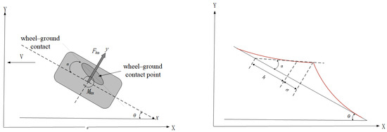
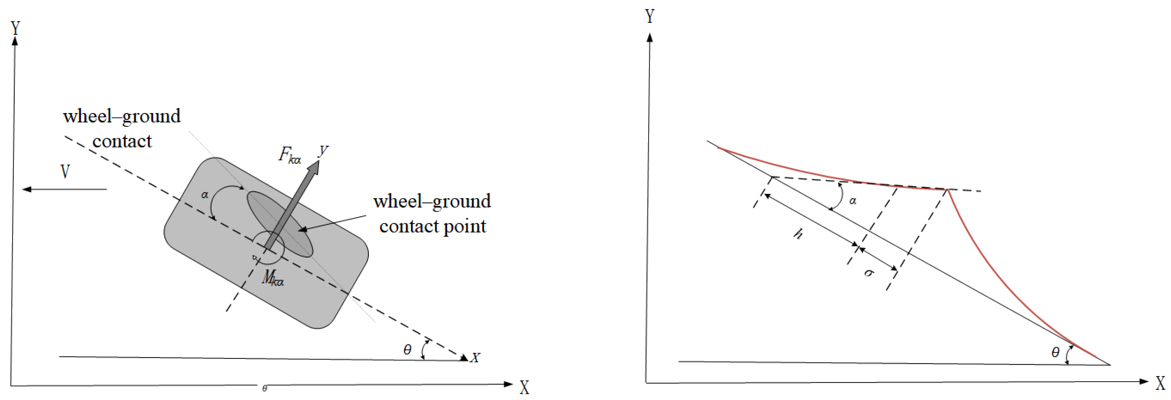
The tire lateral force and self-aligning moment are the main sources of self-excited shimmy vibration in the nose landing gear. In this paper, a tire model based on the von Schlippe string theory is used to describe the relation between tire lateral deformation and slip angle. With a small number of parameters, this model can describe the dynamic relation among tire lateral deformation, lateral restoring force, and self-aligning moment. As shown in Figure 2, the relation between the tire slip angle and tire lateral deformation is determined by the tire relaxation length : .
Figure 2.
Schematic of the relation between tire lateral deformation and slip angle.
Considering the saturation characteristics of tire force and moment under large slip-angle conditions, the tire self-aligning moment is represented by a piecewise sine function:
where is the tire self-aligning moment coefficient and is the maximum slip angle.
The tire lateral restoring force is represented in a double-arctangent form,
where is the tire lateral restoring force coefficient.
The above nonlinear tire force model accounts for both the approximately linear characteristics at small slip angles and the saturation characteristics at large slip angles. Therefore, the nonlinearities in this model mainly originate from the geometric coupling caused by the non-zero strut rake angle, the nonlinear characteristics of the tire lateral restoring force and tire self-aligning moment, and the coupling relation among strut torsion, strut lateral bending, and tire lateral deformation.
According to the virtual-work principle, the tire self-aligning moment and tire lateral restoring force are projected onto the generalized coordinate directions of strut torsion and lateral bending. The generalized force corresponding to the torsional degree of freedom is obtained as
where the first term is the tire self-aligning moment, the second term is the moment about the strut caused by the tire lateral force, and the third term is the additional moment generated by the coupling between vertical load and rake angle.
The generalized force corresponding to the lateral bending degree of freedom is:
where the first term is the moment about the strut lateral bending axis caused by the tire lateral force, and the last two terms are the additional roll moments induced by the vertical load.
The tire lateral deformation and the equivalent angular displacement of the shimmy damper do not directly correspond to external generalized forces. Their dynamic relations are determined by the tire lateral-deformation compatibility equation and the shimmy damper mechanical equilibrium equation, respectively.
2.4. State-Space Equations
Substituting the tire force model, generalized-force expressions, shimmy damper mechanical equilibrium relation, and tire lateral-deformation compatibility equation into the Lagrange equations yields the six-dimensional nonlinear shimmy dynamic equations of the nose landing gear, as shown in Equations (11)–(14).
Dynamic equation of strut torsion:
Dynamic equation of strut lateral bending:
After neglecting the rotational inertia of the shimmy damper, the shimmy damper mechanical equilibrium equation can be written as
The tire lateral-deformation compatibility equation based on the von Schlippe string theory is
where h is the half length of the tire contact line.
From Equations (11)–(14), the six-dimensional state-space equation can be obtained:
The model parameters are taken from the nose landing gear shimmy model proposed in [2], and their values are listed in Table 1.
Table 1.
Model parameters of the nose landing gear and their values.
3. Effects of Shimmy Damper Parameters on the Zero-Shimmy Region
Based on the established nonlinear shimmy model of the nose landing gear, Hopf bifurcation analysis and numerical continuation are used to investigate the effects of shimmy damper parameters on the stability boundaries. Nose landing gear shimmy is a self-excited vibration induced by tire-ground coupling feedback. No external periodic excitation is applied in the model, and the taxiing speed V is introduced only as a system operating parameter. When the speed, load, or shimmy damper parameters reach critical conditions, the system equilibrium loses stability and periodic shimmy is generated through Hopf bifurcation.
Therefore, the Hopf bifurcation curve can be used as the critical boundary between stable and unstable regions. A conventional hydraulic shimmy damper mainly reduces the torsional vibration response through damping dissipation. However, both shimmy damper damping and shimmy damper stiffness change the dynamic coupling relation between the torsional channel and the lateral channel. Thus, shimmy damper parameter design must simultaneously consider the condition for shimmy disappearance on the low-damping side and the instability boundary on the high-damping side.
MatCont is used in this paper to perform numerical continuation of the Hopf bifurcation curves and two-parameter stability boundaries. To ensure the reproducibility of the calculation results, the initial continuation step size is set to 0.01, the minimum step size is set to , and the maximum step size is set to 0.1. The variable tolerance and function tolerance are both set to , the test-function tolerance is set to , and the maximum number of continuation points is set to 300,000. The Hopf bifurcation points are identified by the crossing of the real parts of the eigenvalues of the linearized system at equilibrium through zero, and the stability boundaries in different parameter planes are further obtained through two-parameter continuation.
3.1. Dual-Boundary Effect of Shimmy Damper Damping
The shimmy damper damping is the core parameter in hydraulic shimmy damper design and directly affects the capability for shimmy-energy dissipation. Under low-damping conditions, the system is prone to tire-induced torsional shimmy caused by coupling between tire slip-angle nonlinearity and strut torsional motion. Under high-damping conditions, excessive shimmy damper damping may strengthen the dynamic coupling between the torsional and lateral degrees of freedom, leading to lateral shimmy or structural torsional shimmy. Therefore, an appropriate value of shimmy damper damping should satisfy both the lower critical damping constraint and the upper critical damping constraint.
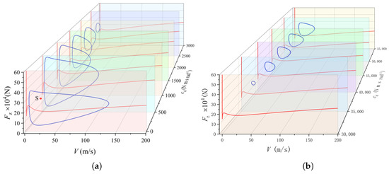
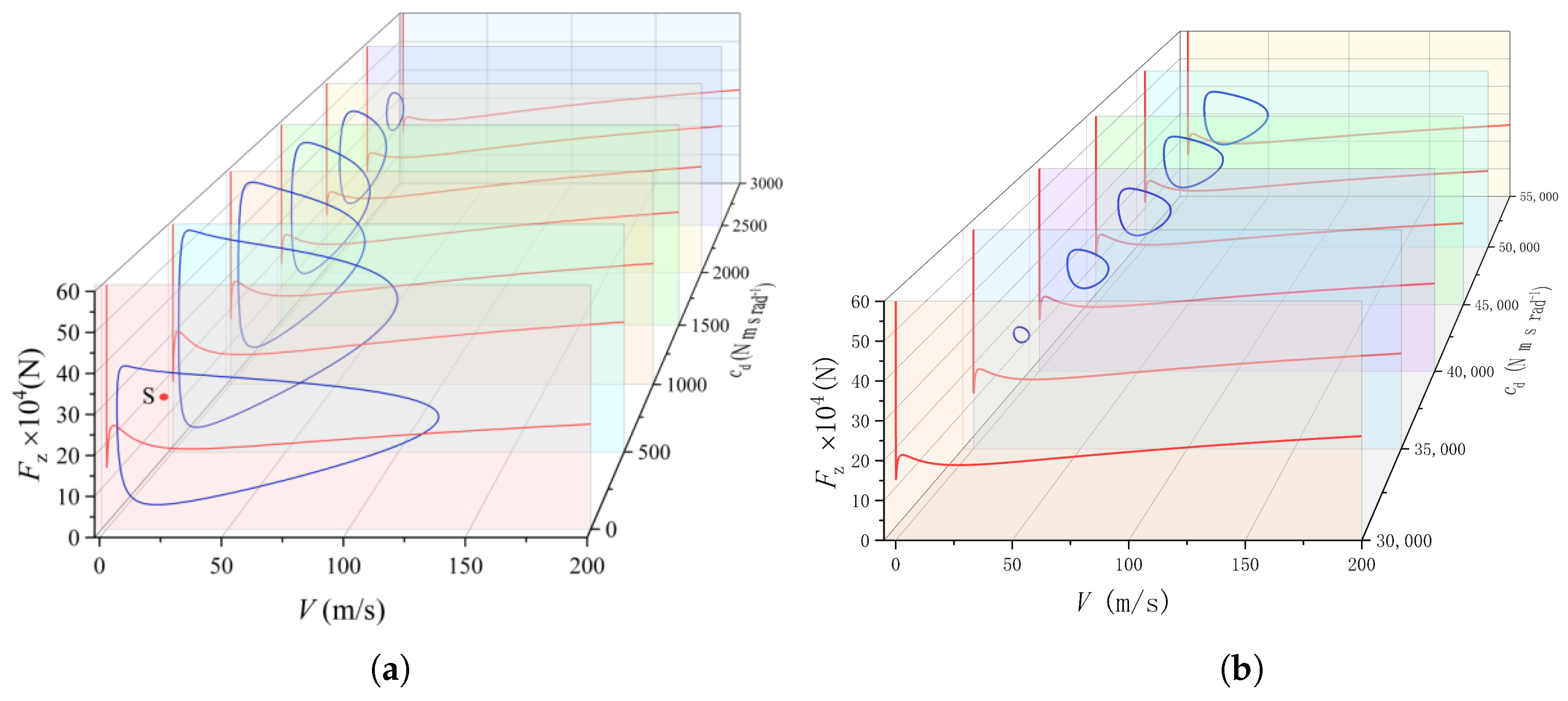
To analyze the effect of on the shimmy instability boundary, a low-damping interval of 500–3000 N·m·s/rad and a high-damping interval of 30,000–55,000 N·m·s/rad are selected for comparison. The low-damping interval is used to observe the gradual disappearance of tire-induced torsional shimmy as damping increases, whereas the high-damping interval is used to identify lateral shimmy or structural torsional shimmy induced by excessive damping. Using the vertical load and taxiing speed V as continuation parameters, two-parameter bifurcation analysis is performed, as shown in Figure 3. The blue curves are torsional Hopf bifurcation curves dominated by torsional vibration, and the system undergoes tire-induced torsional shimmy instability inside the regions enclosed by these curves. The red curves are lateral Hopf bifurcation curves dominated by lateral bending vibration, and the system undergoes lateral shimmy instability in the parameter region above these curves.
Figure 3.
-V two-parameter Hopf bifurcation diagrams under different shimmy damper damping values. (a) -V two-parameter bifurcation with between 0 and 3000 N·m·s/rad; (b) -V two-parameter bifurcation with between 30,000 and 55,000 N·m·s/rad.
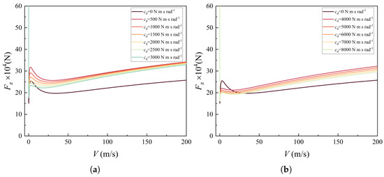
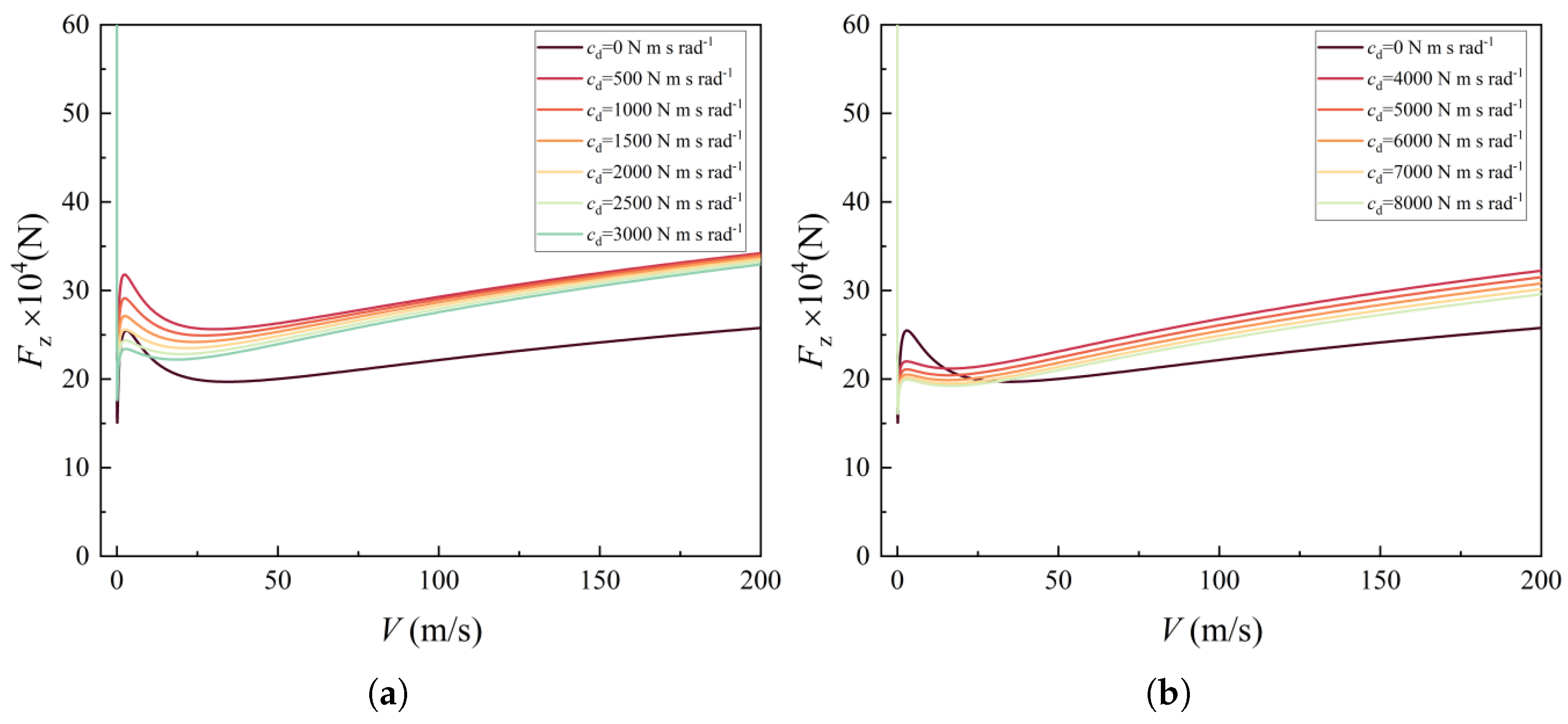
The results show that, in the low-damping interval, the torsional shimmy instability region contracts significantly as increases. When increases to approximately 3000 N·m·s/rad, tire-induced torsional shimmy is suppressed, indicating that an appropriate increase in damping can improve the low-damping-side stability margin. However, increasing damping is not always beneficial to stability. When enters the high-damping interval, a torsional Hopf bifurcation boundary reappears, and the instability region expands as damping increases. At this stage, shimmy is no longer dominated mainly by tire slip-angle nonlinearity but is related to elastic deformation and modal coupling of the strut and shimmy damper linkage system. The lateral Hopf bifurcation curve also shows a non-monotonic response to , as shown in Figure 4. When increases from zero to a small damping value of 500 N·m·s/rad, the lateral bifurcation boundary moves upward and lateral stability improves. As continues to increase, the lateral bifurcation boundary moves downward, especially in the low-speed range. This indicates that, under high-damping conditions, lateral shimmy may become the upper boundary limiting shimmy damper design before torsional shimmy does.
Figure 4.
Lateral Hopf bifurcation boundaries under different shimmy damper damping values. (a) Lateral shimmy Hopf bifurcation curve (lower shimmy damper damping); (b) lateral shimmy Hopf bifurcation curve (higher shimmy damper damping.
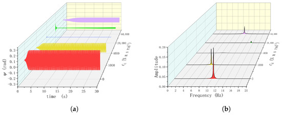
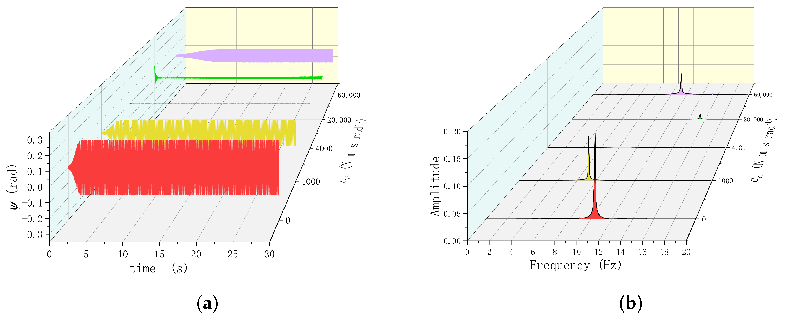
To further illustrate the influence of damping, time-domain and frequency-domain analyses are conducted at V = 25 m/s and = 360 kN, as shown in Figure 5. This condition lies in a typical taxiing speed range during aircraft takeoff and landing, and without a shimmy damper, the system is clearly unstable, making it suitable for observing the transition of shimmy damper damping from vibration suppression to instability induction. When = 1000 N·m·s/rad, torsional shimmy still exists, but its amplitude is significantly lower than that without a shimmy damper, and the dominant frequency decreases from about 10 Hz to about 7 Hz. When = 4000 N·m·s/rad, torsional shimmy disappears and no obvious dominant peak is observed in the frequency domain, indicating that the shimmy damper effectively suppresses shimmy. When = 20,000 N·m·s/rad, periodic torsional shimmy occurs, with a dominant frequency of about 15 Hz. Its closeness to the lateral structural natural frequency indicates that the dominant vibration mode has transformed from tire-induced torsional shimmy to a structure-related mode. When = 60,000 N·m·s/rad, a large-amplitude periodic oscillation reappears, indicating that excessive damping can reintroduce torsional shimmy.
Figure 5.
Time histories and spectra under different shimmy damper damping values. (a) Time histories; (b) spectra.
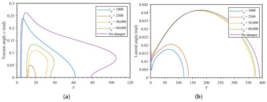
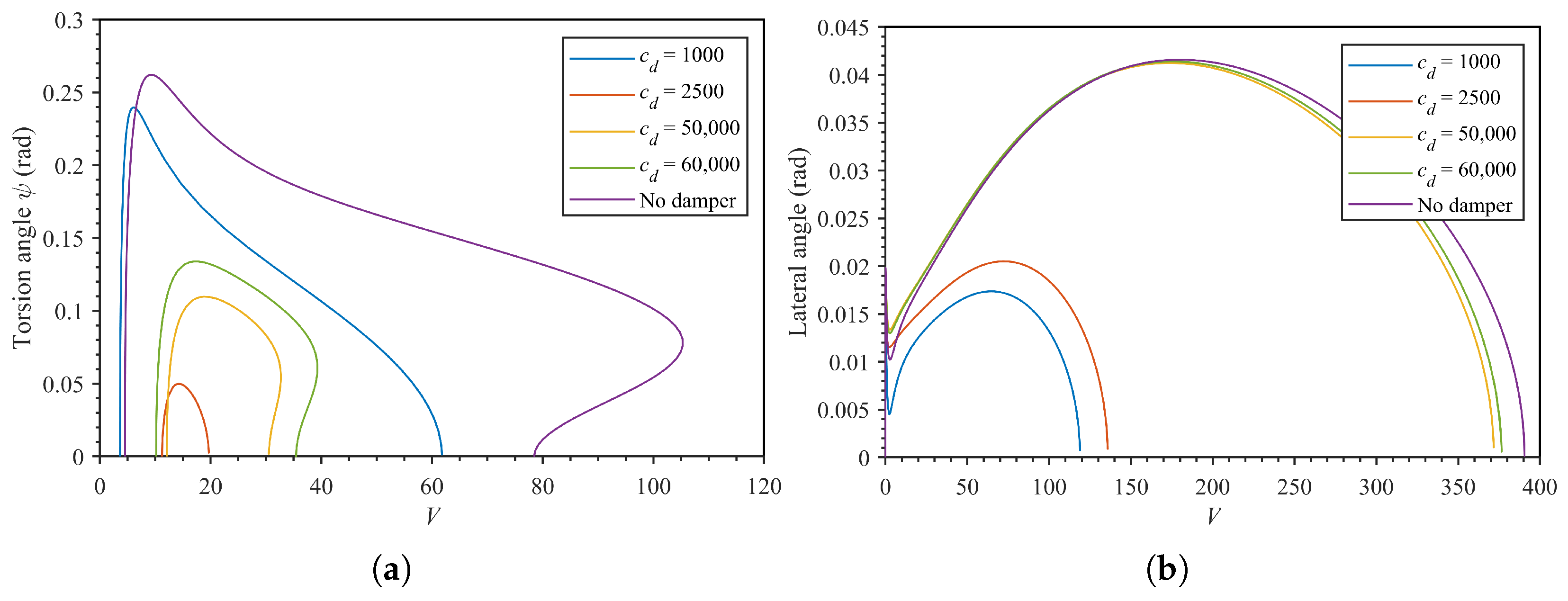
Based on the above time-domain and frequency-domain analyses at the typical speed point, Figure 6 presents the single-parameter bifurcation diagrams of the torsional and lateral responses under different values. The results show that, without a shimmy damper, the system exhibits obvious shimmy instability over a wide speed range. The torsional angle amplitude increases rapidly in the low-speed range and reaches approximately 0.262 rad near m/s. The lateral response amplitude mainly develops in the medium- and high-speed ranges and reaches approximately 0.0416 rad near m/s. After the shimmy damper is introduced, a lower damping value can effectively reduce the shimmy response. When N·m·s/rad, the peak torsional angle decreases to approximately 0.240 rad, and the peak lateral response decreases to approximately 0.0174 rad. When N·m·s/rad, the peak torsional angle further decreases to approximately 0.050 rad, and the peak lateral response is approximately 0.0205 rad, indicating that moderate damping provides effective shimmy suppression. However, when increases to 50,000 and 60,000 N·m·s/rad, the torsional angle amplitude increases again, and the peak lateral response also approaches the level without a shimmy damper. This indicates that excessive damping strengthens torsional-lateral coupling and causes shimmy response to reappear on the high-damping side.
Figure 6.
Single-parameter bifurcation diagrams under different shimmy damper damping values. (a) Torsional bifurcation diagram; (b) lateral bifurcation diagram.
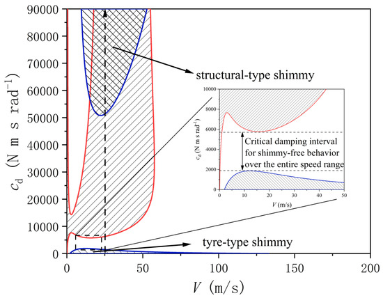
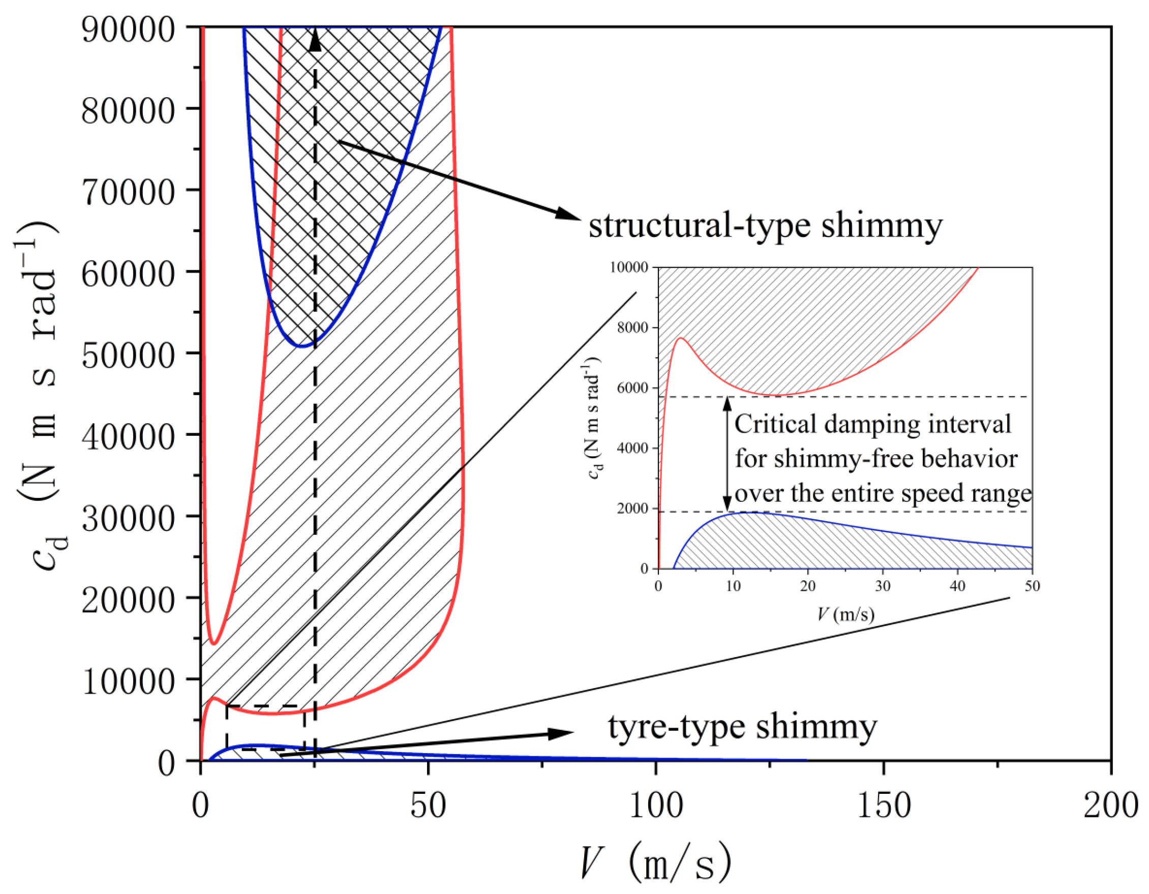
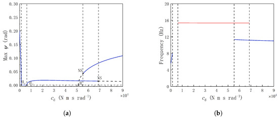
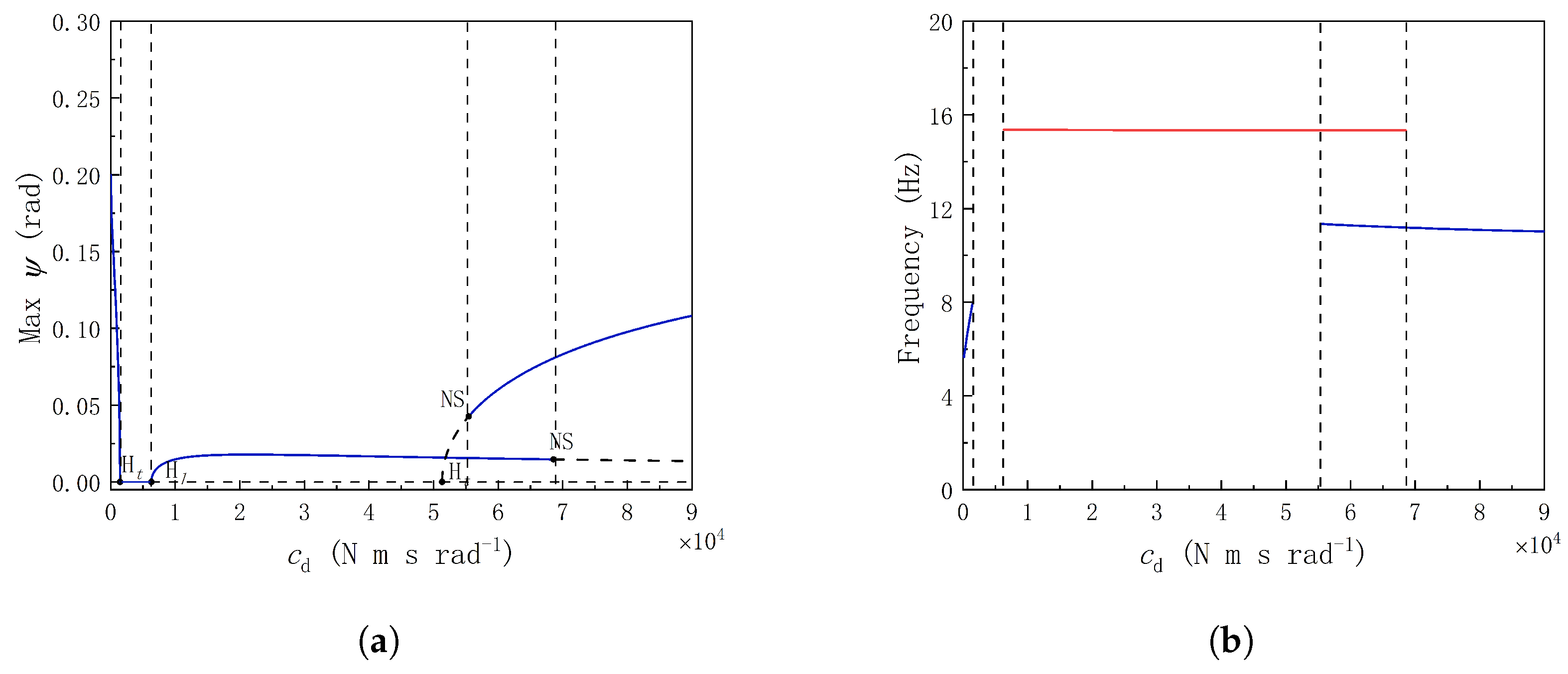
To quantitatively determine the zero-shimmy damping interval over the full speed range, two-parameter bifurcation analysis is further conducted at = 200 kN in the -V plane, as shown in Figure 7. In the figure, the left hatched region is the tire-induced torsional shimmy instability region, the right hatched region is the lateral shimmy instability region, the cross-hatched region represents the coupled shimmy region in which both torsional and lateral instabilities occur, and the remaining region is the zero-shimmy stable region. The results show that, when = 0–2000 N·m·s/rad, the critical speed range for tire-induced torsional shimmy gradually narrows as damping increases. When = 2000–5800 N·m·s/rad, neither torsional shimmy nor lateral shimmy appears within the examined taxiing speed range, forming a continuous zero-shimmy region. When > 5800 N·m·s/rad, lateral shimmy occurs near V = 25–60 m/s. When > 50,000 N·m·s/rad, torsional shimmy reappears near the low-speed range. At V = 25 m/s, the variation in torsional limit-cycle amplitude and frequency with is shown in Figure 8. As increases, the limit-cycle amplitude of tire-induced torsional shimmy gradually decreases and eventually disappears; in the high-damping interval, structural torsional shimmy reappears. The frequency variation also illustrates the difference between the two types of torsional shimmy: the low-damping instability corresponds to tire-induced torsional shimmy, whereas the high-damping instability is closer to torsional shimmy dominated by the structural mode.
Figure 7.
At = 200 kN, shimmy damper damping -V two-parameter bifurcation diagram.
Figure 8.
Variation in torsional limit-cycle amplitude and frequency with shimmy damper damping. (a) Variation in maximum torsional limit-cycle amplitude with shimmy damper damping; (b) variation in torsional limit-cycle frequency with shimmy damper damping.
The above results show that shimmy damper damping has a distinct non-monotonic effect on shimmy stability. In the low-damping stage, increasing mainly improves energy dissipation and contracts the tire-induced torsional shimmy region. In the moderate-damping stage, both torsional shimmy and lateral shimmy are suppressed, and a zero-shimmy stable region is formed. In the high-damping stage, excessive damping strengthens torsional-lateral coupling and changes the modal energy distribution, causing lateral shimmy or structural torsional shimmy to occur. Therefore, the conventional design practice of determining the design value only by multiplying the critical damping for torsional shimmy by a safety factor may make the shimmy damper damping exceed the high-damping-side stability boundary and thereby induce new shimmy instability.
3.2. Effect of Shimmy Damper Stiffness on the Stability Region
The shimmy damper stiffness determines the relative motion capability between the shimmy damper and the torque links and thus affects the effective energy dissipation of the shimmy damper. If is too low, the wheel self-centering constraint is insufficient, and taxiing stability may deteriorate. If is too high, the relative motion between the shimmy damper piston and the torque links is restricted, the system tends toward torsional lock-up, and the damping energy-dissipation effect cannot be fully utilized. Therefore, must be balanced between self-centering constraint and shimmy suppression performance.
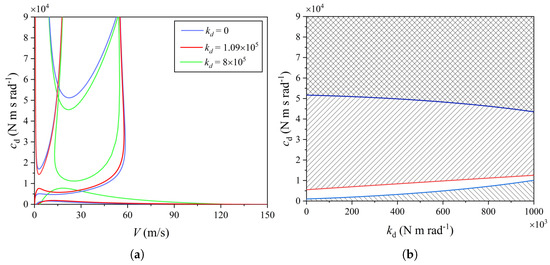
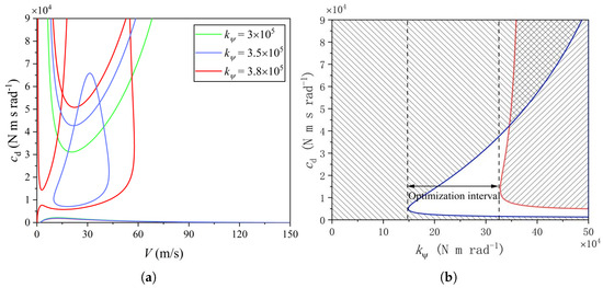
Two boundary conditions, and N·m/rad, are selected and compared with the nominal-stiffness condition. The -V two-parameter bifurcation results are shown in Figure 9a. When = 0, the structural torsional shimmy boundary is basically close to that under the nominal condition, indicating that reduced shimmy damper stiffness has a limited effect on structural torsional instability. In the range V = 5–120 m/s, the tire-induced torsional shimmy and lateral shimmy boundaries move downward slightly, but the zero-shimmy region is not significantly widened. When increases to N·m/rad, the critical damping for structural torsional shimmy decreases, the tire-induced torsional shimmy and lateral shimmy boundaries move toward the middle of the stable region, and the zero-shimmy region narrows significantly. Further at V = 25 m/s, a - two-parameter bifurcation diagram is constructed, as shown in Figure 9b. The results show that, as increases, the zero-shimmy region shifts overall toward higher damping, but its width decreases markedly. This is because a larger raises the lower critical damping for tire-induced torsional shimmy while also strengthening torsional-lateral modal coupling and reducing the upper critical damping for lateral shimmy, so the stable region is squeezed by the upward movement of the lower boundary and the downward movement of the upper boundary. Thus, conventional hydraulic shimmy dampers have intrinsic parameter constraints: too little damping cannot suppress tire-induced torsional shimmy, excessive damping may induce lateral or structural shimmy, and excessive stiffness further compresses the available damping interval. Therefore, the key to zero-shimmy design over the full speed range is not simply increasing damping or stiffness, but identifying the dual boundaries of the zero-shimmy region and completing the damping-stiffness matching design within them.
Figure 9.
Effects of shimmy damper stiffness on the -V and - stability boundaries. (a) For different values, -V two-parameter bifurcation diagrams; (b) - two-parameter bifurcation diagram.
4. Effects of Structural Parameters on the Zero-Shimmy Region
The previous section shows that the stable damping interval of the hydraulic shimmy damper is jointly constrained by the low-damping-side torsional shimmy boundary and the high-damping-side lateral/structural shimmy boundary. For a given landing gear configuration, shimmy damper parameters can only be matched within the existing stability boundaries, whereas structural parameters such as trail, strut torsional stiffness, and rake angle directly change tire moment feedback, system natural modes, and torsional-lateral coupling strength.
4.1. Effect of Trail on the Existence of the Stability Region
The mechanical trail e affects the moment generated by the tire’s lateral force about the strut rotation axis by changing the effective trail . The trail determines the lever arm through which tire lateral-force feedback enters the steering/torsional channel. Therefore, it is not only a geometric layout parameter but also a key design parameter that determines the strength of tire self-excited feedback and torsional-lateral coupling.
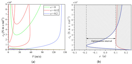
The bifurcation results shown in Figure 10 indicate that the trail has an existence effect on the zero-shimmy region. When e = 0, compared with the nominal condition, the lateral shimmy boundary disappears within the examined speed range, the structural torsional shimmy boundary moves downward, the tire-induced torsional shimmy boundary moves upward, and the zero-shimmy damping interval is significantly widened. When e = 0.2 m, although the structural torsional shimmy boundary disappears, the lateral shimmy region expands significantly and approaches the tire-induced torsional shimmy boundary near V = 12–33 m/s, causing the zero-shimmy region over the full speed range to disappear, as shown in Figure 10a. The further -e bifurcation results shown in Figure 10b indicate that, when e < −0.18 m, the effective trail is negative, the self-centering capability of the wheel is insufficient, and the system is prone to torsional instability. When e lies in the range of −0.18 to 0.10 m, the system has a relatively wide zero-shimmy damping interval. As e continues to increase, tire lateral-moment feedback is amplified, and the lateral shimmy region expands significantly and covers most damping values. Therefore, the trail is a structural parameter that determines whether the zero-shimmy region can be formed. Too small or negative trail weakens wheel self-centering capability and leads to insufficient torsional stability, whereas excessive trail strengthens lateral-moment feedback and lowers the high-damping-side stability boundary.
Figure 10.
Effects of trail on the -V and -e stability boundaries. (a) For different e values, -V two-parameter bifurcation diagrams; (b) -e two-parameter bifurcation diagram.
4.2. Upper-Boundary Regulation by Strut Torsional Stiffness
The strut torsional stiffness determines the basic characteristics of the torsional mode of the nose landing gear and also affects the coupling strength between torsional motion and lateral bending motion. If is too low, the strut has insufficient torsional resistance, and torsional shimmy is likely under low-damping conditions. If is too high, the torsional modal frequency of the system increases, and the coupling of torsional motion to the lateral degree of freedom is enhanced, which may lower the upper critical damping for lateral shimmy.
Different values are selected for -V two-parameter bifurcation analysis, as shown in Figure 11a. When N·m/rad, the lateral shimmy bifurcation boundary disappears in the range V = 5–85 m/s, structural torsional shimmy becomes the main limiting factor on the high-damping side, and the zero-shimmy damping interval is significantly widened. As increases, the lateral shimmy instability region reappears and gradually expands, and the critical damping for structural torsional shimmy also changes, whereas the tire-induced torsional shimmy boundary is insensitive to changes in . At V = 25 m/s, the - two-parameter bifurcation shown in Figure 11b further indicates that mainly affects the high-damping-side stability boundary. A lower causes insufficient torsional restoring capability, making it difficult for the system to form a stable region. A moderate helps widen the zero-shimmy damping interval. When N·m/rad, torsional-lateral modal coupling is strengthened, causing the lateral shimmy region to expand and the stable region to be compressed.
Figure 11.
Effects of strut torsional stiffness on the -V and - stability boundaries. (a) For different values, -V two-parameter bifurcation diagrams; (b) - two-parameter bifurcation diagram.
Thus, a larger strut torsional stiffness is not necessarily more favorable. The engineering design objective is not simply to increase torsional stiffness but to ensure basic torsional resistance while avoiding the downward movement of the high-damping-side shimmy boundary caused by excessive stiffness. The strut torsional stiffness should be matched as an important structural parameter for regulating the high-damping-side boundary.
4.3. Fine-Tuning Effect of the Rake Angle on the Stability Boundary
The strut rake angle mainly affects shimmy stability through two paths. First, it changes the kinematic relation between the wheel steering angle and the strut torsional angle. Second, it changes the effective trail and introduces geometric coupling terms among the vertical load, torsional motion, and lateral motion. Therefore, the rake angle affects the position of the stability boundary, but its role is usually constrained by the overall landing gear layout, retraction mechanism, and structural space.
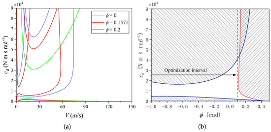
Figure 12a gives the -V two-parameter bifurcation results under different rake angles. When = 0, compared with the nominal condition, the lateral shimmy bifurcation boundary disappears, the structural torsional shimmy boundary moves downward, the tire-induced torsional shimmy boundary moves upward in the range V = 5–120 m/s, and the zero-shimmy damping interval is significantly widened. When = 0.2 rad, the lateral shimmy boundary reappears and moves downward slightly, the structural torsional shimmy boundary changes slightly, and the overall variation in the tire-induced torsional shimmy boundary is relatively small. At V = 25 m/s, the - two-parameter bifurcation diagram is shown in Figure 12b. It can be seen that when the rake angle < 0.1 rad, the system has a relatively wide zero-shimmy damping interval. When > 0.1 rad, the lateral shimmy region expands and compresses the zero-shimmy damping interval. Therefore, the influence of the rake angle on the stability boundary is weaker than that of the trail and strut torsional stiffness. In engineering practice, a reasonable approach is to use the rake angle as a correction parameter for checking shimmy damper damping margin while satisfying the constraints of overall layout, retraction mechanism, and structural space.
Figure 12.
Effects of rake angle on the -V and - stability boundaries. (a) For different values, -V two-parameter bifurcation diagrams; (b) - two-parameter bifurcation diagram.
Based on the above results, the shimmy-stability design of a nose landing gear over the full speed range can adopt a hierarchical design strategy: first determine the trail so that the system has the basic condition for forming a zero-shimmy region; then design the strut torsional stiffness to avoid torsional instability caused by low stiffness and lateral instability caused by high stiffness; next adjust the rake angle within the constraints of the overall configuration; and finally select the shimmy damper damping and stiffness within the dual-boundary range after the structural parameters are determined. This procedure avoids relying solely on shimmy damper damping to compensate for unreasonable structural parameter values.
5. Wide-Speed-Range Shimmy Suppression Characteristics of the Inerter-Based System
The preceding analysis shows that the stable damping interval of a conventional hydraulic shimmy damper is constrained by dual boundaries and that excessive shimmy damper stiffness further compresses the available damping space. It is difficult to further widen the zero-shimmy region over the full speed range by adjusting only conventional damping and stiffness parameters. To improve this situation, an inerter is introduced to construct an inerter-based shimmy suppression system. The system-equivalent inertia and torsional-lateral modal coupling relation are adjusted through inerter parameters, thereby improving shimmy suppression capability over a wide speed range.
5.1. Inerter-Based Shimmy Suppression Model
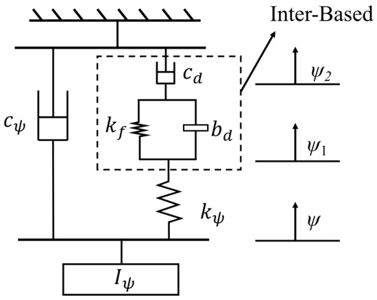
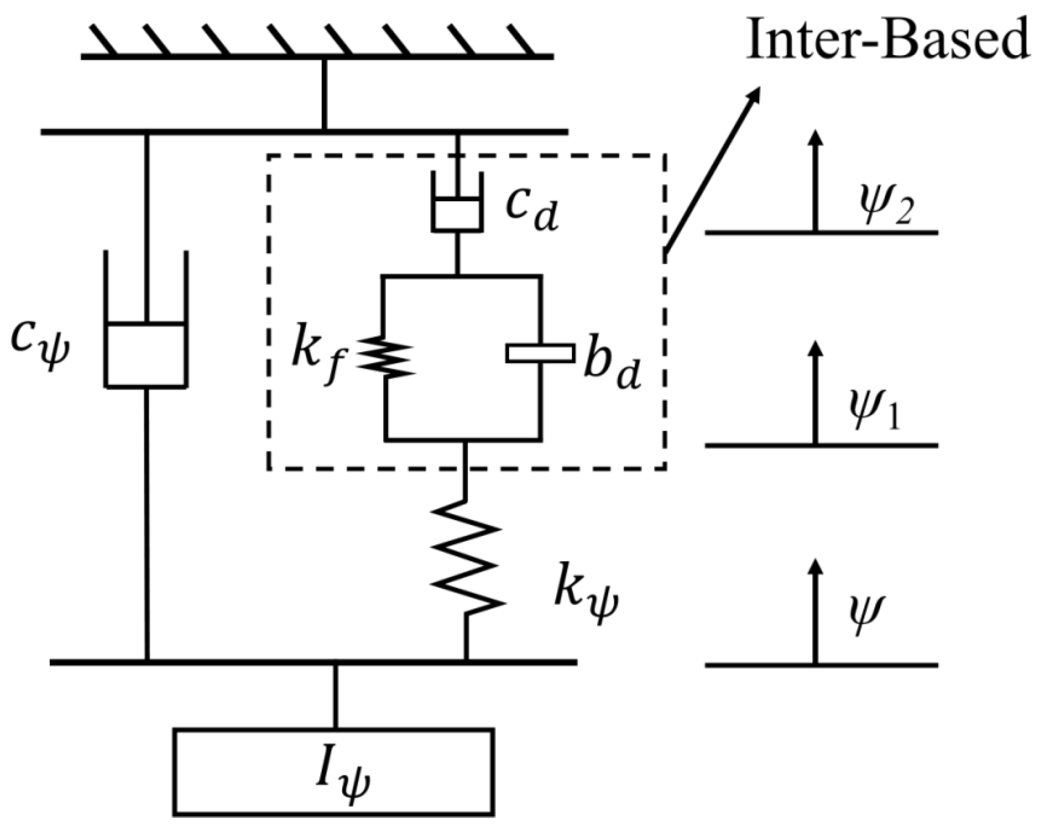
The inerter is a two-terminal dynamic element whose output moment is proportional to the relative angular acceleration between its two terminals. Unlike a spring element, the inerter does not directly introduce static stiffness but changes the dynamic response of the system through inertial coupling. In this paper, a coupled shimmy suppression configuration is adopted in which the inerter is connected in parallel with the tuning stiffness and then in series with the damping , as shown in Figure 13. The inerter is installed between the landing gear torque link and the fixed end of the strut. Here, is the angular displacement at the connection between the shimmy suppression branch and the strut torsional degree of freedom, and is the angular displacement at the connection between the inerter-tuning branch and the damper. The tuning stiffness and inertance coefficient jointly regulate the dynamic characteristics of the shimmy suppression branch, while the damper dissipates the vibration energy transferred to the shimmy suppression branch.
Figure 13.
Schematic of the inerter-based shimmy suppression system configuration.
On the basis of the six-dimensional nose landing gear model, the angular displacements of the two terminals of the inerter element are introduced, and the system state variables are expanded as
After the inerter element is introduced, the strut torsional equation is written as
The moment equilibrium relations at the two terminals of the inerter element are
where is the elastic moment generated by the tuning spring, is the inertial moment generated by the inerter, and is the dissipative moment of the shimmy damper.
Equations (17)–(19), together with the strut lateral-bending equation and the tire lateral-deformation compatibility equation in Section 1, constitute the seven-dimensional nonlinear shimmy dynamic model of the inerter-based shimmy suppression system.
5.2. Regulation of the Stability Region by Inerter Parameters
The stability of the inerter-based shimmy suppression system is mainly affected by the inertance coefficient and the tuning stiffness . The parameter determines the equivalent inertial action strength of the inerter element, and determines the tuning relation between the inerter branch and strut torsion. If is too small, the inerter branch cannot effectively participate in torsional-mode regulation. If is too large, the inerter branch tends toward rigid connection, which strengthens the coupling between torsional and lateral motions and compresses the stability region.
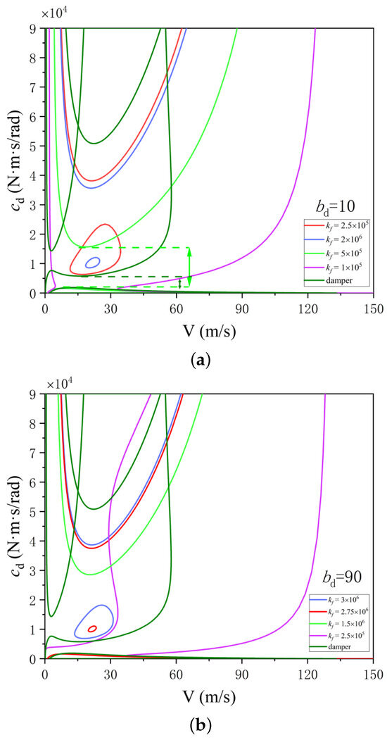
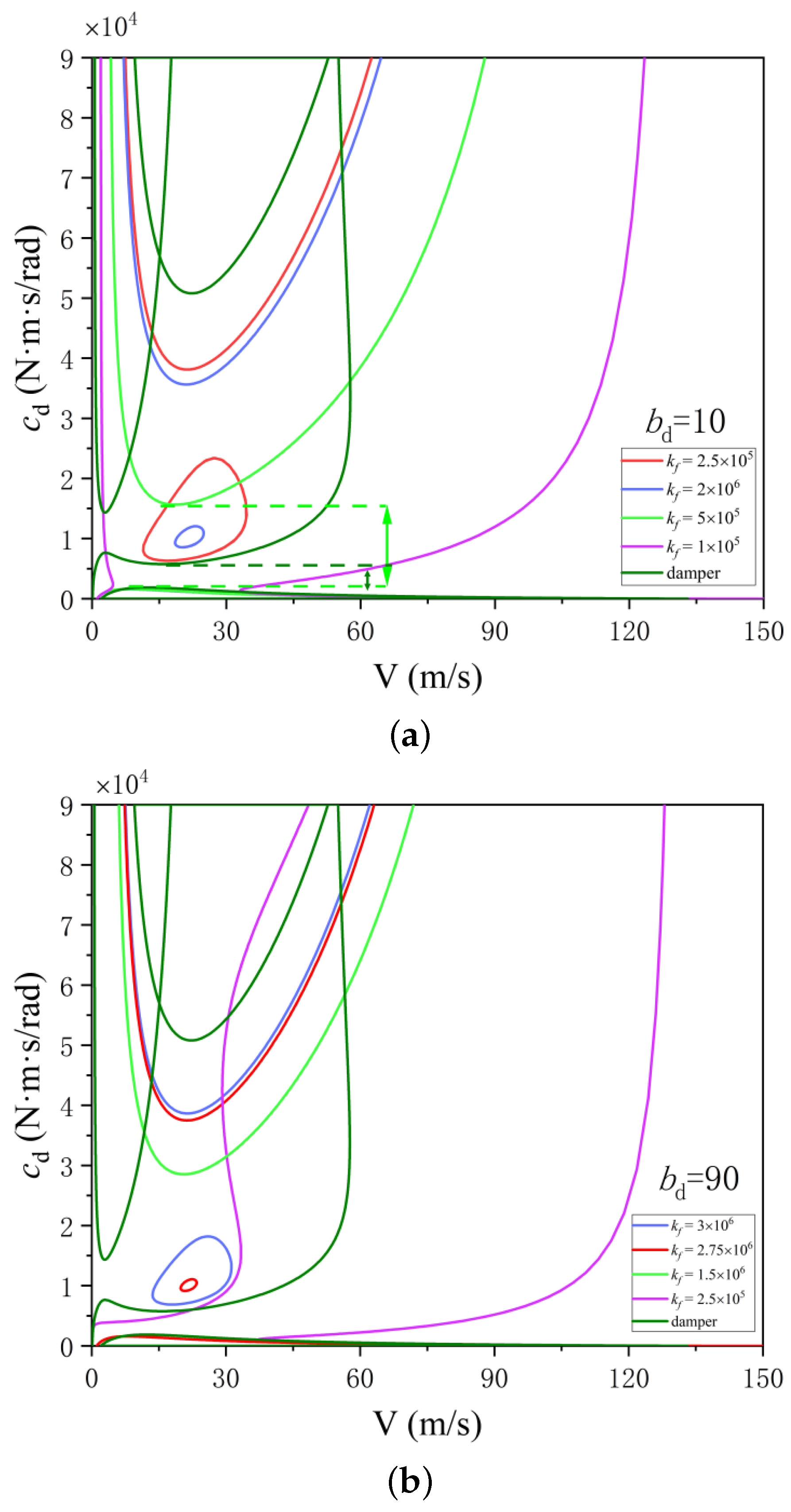
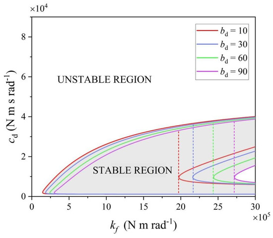
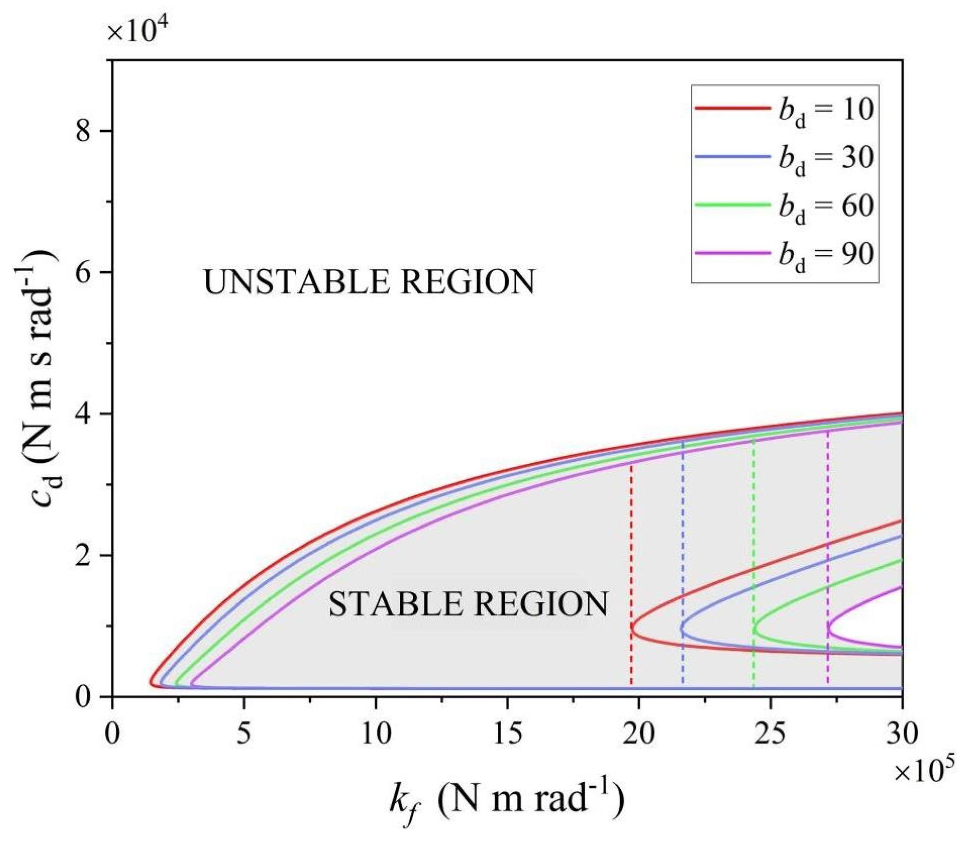
To examine the change in stability boundaries as the inerter effect varies from weak to strong, two typical parameter sets, = 10 N·m·s2/rad and = 90 N·m·s2/rad, are selected for -V two-parameter bifurcation analysis. When = 10 N·m·s2/rad, the tuning stiffness has a non-monotonic effect on the stability region. When N·m/rad, the inerter branch is insufficiently tuned, the structural torsional shimmy boundary approaches the tire-induced torsional shimmy boundary, and the system has difficulty forming a continuous zero-shimmy region. When increases to N·m/rad, the structural torsional shimmy boundary moves upward and separates from the tire-induced torsional shimmy boundary, and the system forms a continuous zero-shimmy region within the examined speed range. At this point, the stable damping interval is widened from 2000–5800 N·m·s/rad for the conventional hydraulic shimmy damper to approximately 2000–15,000 N·m·s/rad, and the upper critical damping on the high-damping side is significantly increased. Meanwhile, the lateral shimmy bifurcation boundary disappears, indicating that the inerter-based shimmy suppression system can effectively alleviate the restriction imposed by high-damping-side lateral instability on the damping upper limit in conventional design. When continues to increase to a higher level, excessive tuning stiffness strengthens the dynamic coupling between the torsional channel and lateral motion, causing a lateral shimmy instability region to reappear in the low-speed range and expand as increases. When = 90 N·m·s2/rad, the evolution trend of the bifurcation curves is basically consistent with that under the weak-inerter condition, as shown in Figure 14b. The difference is that a larger inertance coefficient can broaden the effective tuning-stiffness range. Under the optimal parameter combination, the upper critical damping of the zero-shimmy region can be increased to 18,000 N·m·s/rad, which is approximately 210% higher than that of the conventional hydraulic shimmy damper.
Figure 14.
-V two-parameter bifurcation diagrams under different inertance coefficients. (a) At = 10 N·m·s2/rad, -V two-parameter bifurcation diagram; (b) at = 90 N·m·s2/rad, -V two-parameter bifurcation diagram.
To further illustrate the matching law between and , at V = 25 m/s, - two-parameter bifurcation diagrams corresponding to different inertance coefficients are constructed, as shown in Figure 15. The gray region denotes the zero-shimmy stable region. The results show that, for a given , has a clear effective range. When is below the lower critical value, the inerter branch is insufficiently tuned, and it is difficult to form a zero-shimmy region. When approaches the optimal range, the stable damping interval reaches its maximum. When continues to increase, the stability region gradually shrinks. As increases, the effective interval and the stable damping interval widen simultaneously. This indicates that the role of the inerter is not simply to increase damping, but to change the dynamic equivalent characteristics of the torsional channel through inertial coupling, thereby adjusting the position of the instability boundary and expanding the available damping design space.
Figure 15.
- two-parameter bifurcation diagrams under different inertance coefficients.
5.3. Shimmy Suppression Mechanism Based on Energy Evolution
A conventional hydraulic shimmy damper mainly dissipates energy through viscous damping, and its energy-dissipation effect depends on the amplitude and phase relation of the relative motion in the shimmy suppression branch. The inerter can introduce inertial coupling between the strut torsional degree of freedom and the shimmy suppression element, allowing vibration energy to transfer to the inerter branch and then be dissipated through the damping element. To explain why the inerter-based system widens the stability region, this paper compares the energy evolution of the primary structure under three schemes: no shimmy suppression device, a conventional hydraulic shimmy damper, and an inerter-based shimmy suppression system.
The instantaneous energy of the landing gear primary structure is defined as
where
To reduce the influence of periodic fluctuations in instantaneous energy on the judgment, the moving-average energy is introduced as the evaluation index:
where N is the number of sampling points within the moving time window, and ti is the ith sampling instant. A lower average energy indicates lower system vibration energy and better shimmy suppression performance.
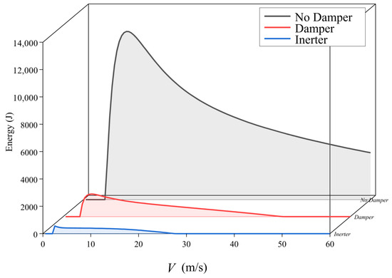
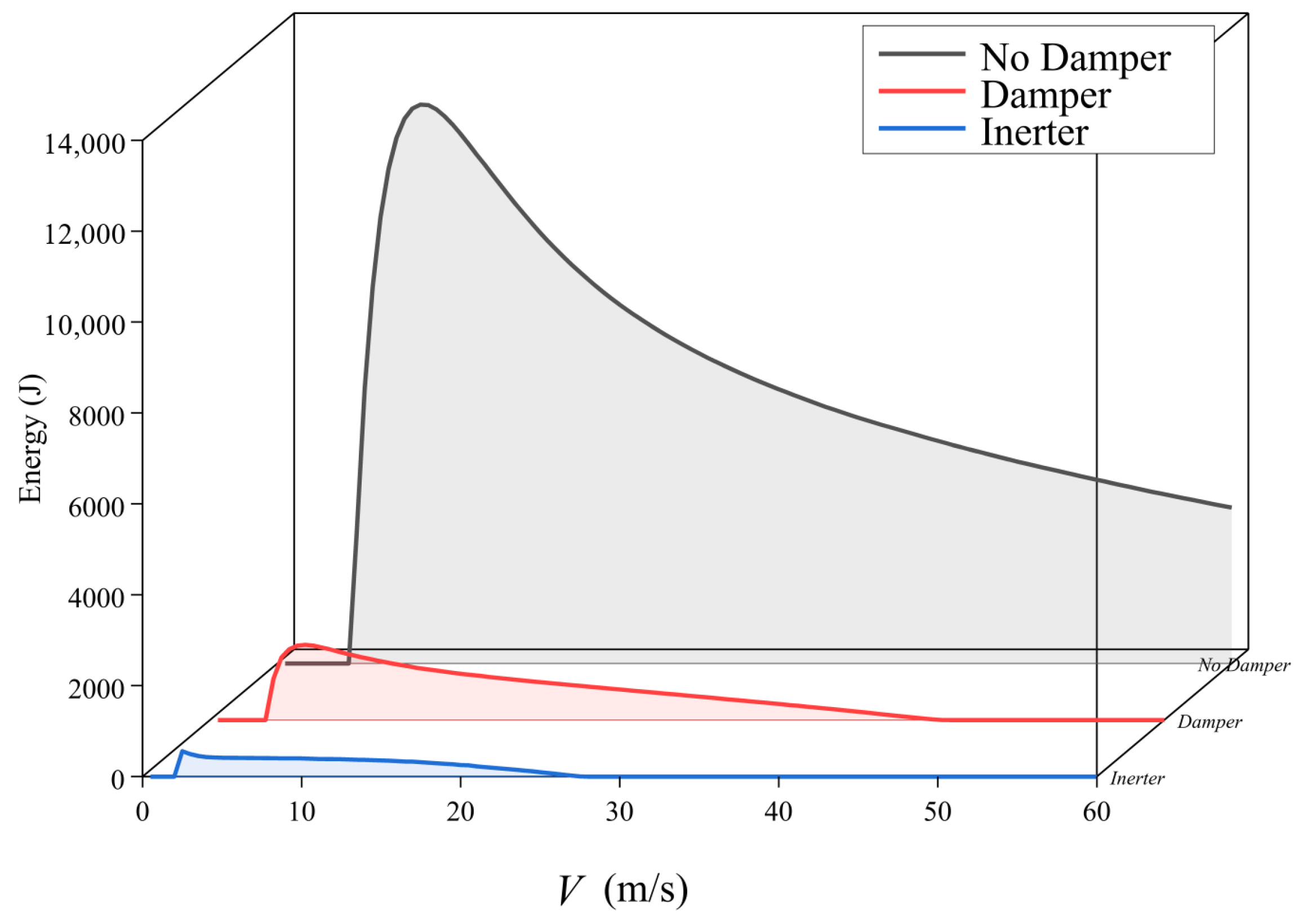
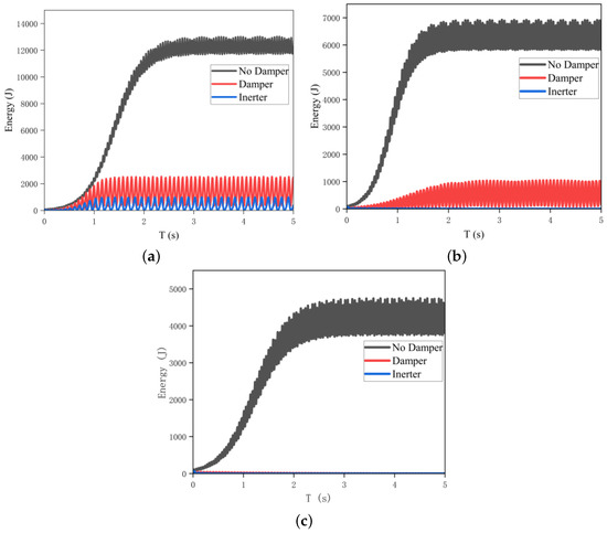
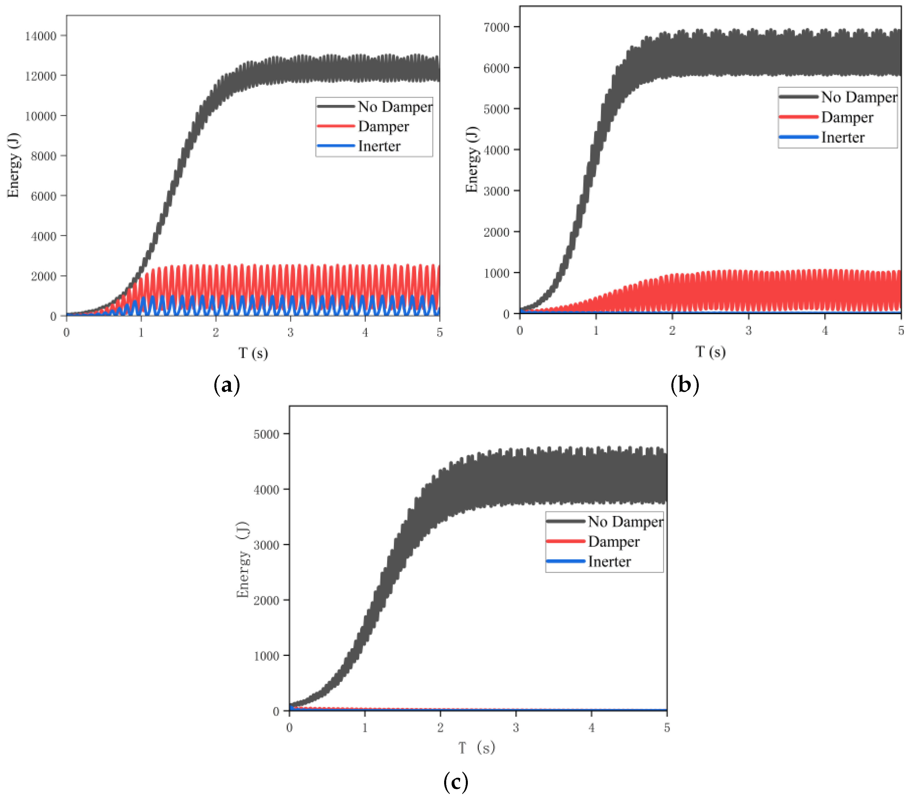
A comparison damping value = 800 N·m·s/rad is selected. This damping is lower than the lower critical damping of the conventional hydraulic shimmy damper and can reflect the shimmy suppression differences among different schemes under low-damping conditions. The variation in average energy with taxiing speed and the evolution of instantaneous energy with time at typical speeds under different schemes are shown in Figure 16 and Figure 17. The results show that, in the low-speed range V = 0–30 m/s, the average energy corresponding to the inerter-based shimmy suppression system is always lower than those of the no-shimmy suppression-device and conventional hydraulic shimmy damper schemes. When V = 30 m/s, the average energy of the inerter-based shimmy suppression system has converged to nearly zero, and shimmy is effectively suppressed, whereas the conventional shimmy damper and the no-shimmy suppression device scheme still maintain relatively high energy levels. When the taxiing speed increases to V = 50 m/s, the average energy of both the conventional hydraulic shimmy damper and the inerter-based shimmy suppression system can gradually dissipate, and both schemes can suppress shimmy, while the no-shimmy suppression-device scheme still maintains a high energy level.
Figure 16.
Comparison of average primary-structure energy under different shimmy suppression schemes.
Figure 17.
Evolution of instantaneous primary-structure energy at different speeds. (a) m/s, N·m·s/rad; (b) m/s, N·m·s/rad; (c) m/s, N·m·s/rad.
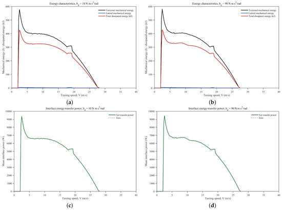
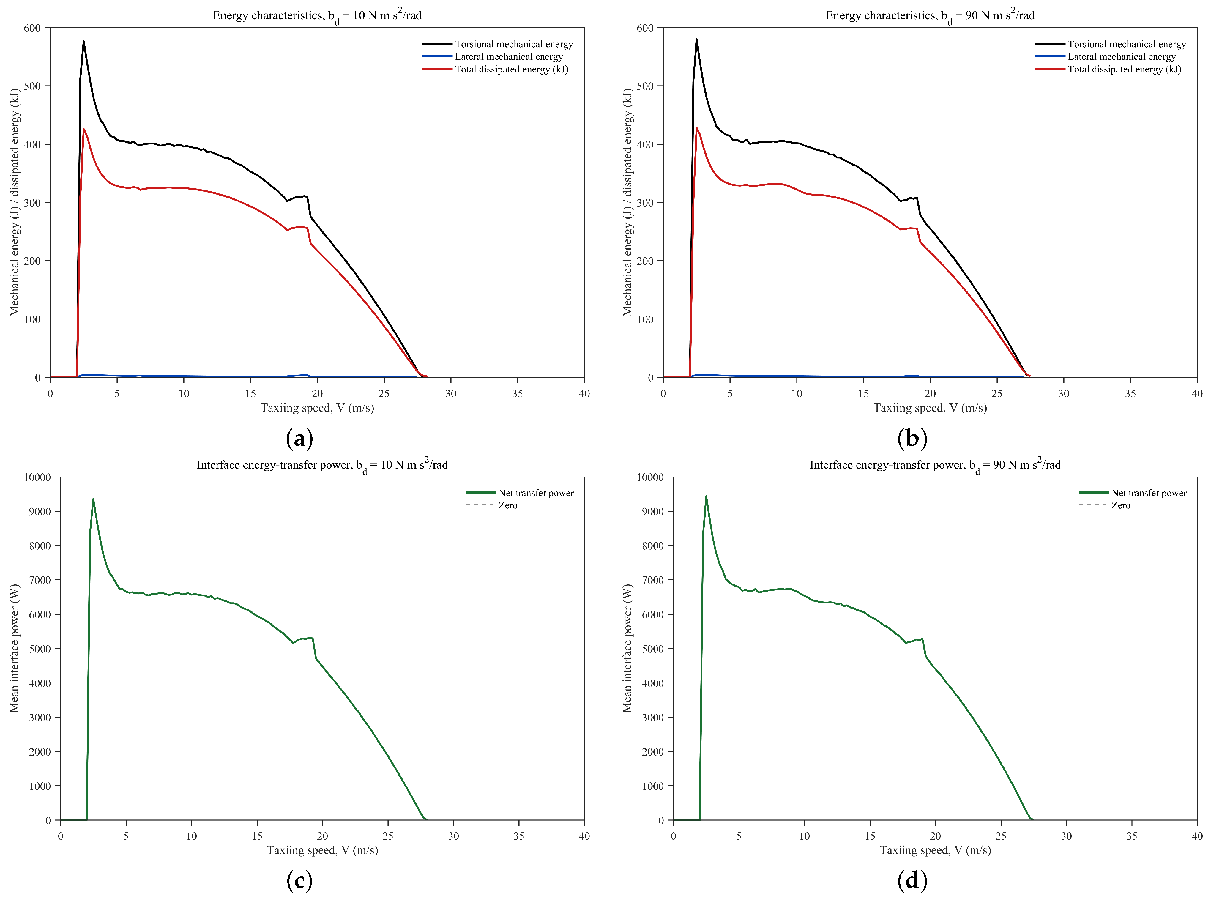
To further clarify the energy mechanism by which the inerter-based shimmy suppression system expands the zero-shimmy region, the mechanical energy of the primary structure, the damping dissipated energy, and the energy-transfer power between the primary structure and the inerter-based shimmy suppression branch are calculated. The torsional mechanical energy and lateral mechanical energy are used to characterize the vibration energy distribution of the torsional mode and lateral mode in the primary structure of the nose landing gear, respectively.
The instantaneous dissipated power of the damper is defined as
Thus, the total dissipated energy of the damper can be expressed as
The energy variation rate of the primary structure can be written as
where
The dissipated power terms are given by
Here, is the input power induced by the tire force, self-aligning moment, and structural geometric coupling. , , and denote the dissipated power of strut torsional damping, strut lateral damping, and damping related to tire lateral deformation, respectively. denotes the dissipated power of the damper in the inerter-based shimmy suppression branch. When , the energy input from tire-structure coupling to the primary structure is greater than the system energy dissipation, and the shimmy response tends to grow or be maintained. When , the system exhibits a net energy-dissipation tendency, and the shimmy response is unlikely to continue increasing and tends to evolve toward a lower energy level.
Meanwhile, to directly describe the energy exchange between the primary structure and the inerter-based shimmy suppression branch, the interface energy-transfer power is defined as
When , shimmy energy is transferred from the primary torsional system to the inerter-based shimmy suppression branch and is further dissipated through the damper.
As shown in Figure 18, within the main shimmy speed range, the torsional mechanical energy is significantly higher than the lateral mechanical energy, indicating that the vibration energy of the primary structure is mainly concentrated in the strut torsional mode under this condition. The low-speed shimmy is still dominated by the self-excited coupling between tire slip-angle nonlinearity and torsional motion. For the two inertance coefficients and 90 N·m·s2/rad, the torsional mechanical energy reaches its peak near the low-speed shimmy region and then gradually decreases as the taxiing speed increases. When the speed increases to approximately 27 m/s, both the shimmy response and the interface energy-transfer power decay to nearly zero, indicating that the shimmy response has been effectively suppressed and that the system gradually enters a low-energy stable state.
Figure 18.
Energy characteristics of the primary structure and interface energy-transfer power under different inertance coefficients. (a) Energy characteristics, N·m·s2/rad; (b) energy characteristics, N·m·s2/rad; (c) interface energy-transfer power, N·m·s2/rad; (d) interface energy-transfer power, N·m·s2/rad.
The variation in the transfer power further reveals the energy-absorption effect of the inerter branch. In the low-speed range, remains positive, indicating that the vibration energy in the primary torsional system can be transferred to the inerter-based shimmy suppression branch through inertial coupling. Unlike the conventional hydraulic shimmy damper, which mainly dissipates energy through relative velocity, the inerter element generates inertial force through relative acceleration and changes the dynamic impedance and phase relation of the torsional channel. This makes the vibration energy in the primary structure easier to transfer to the shimmy suppression branch and to be dissipated by the damping element. Compared with N·m·s2/rad, the peak transfer power is slightly higher when N·m·s2/rad, and the speed at which the mechanical energy decays to nearly zero is slightly lower. This indicates that a larger inertance coefficient can enhance the energy-transfer capability of the shimmy suppression branch.
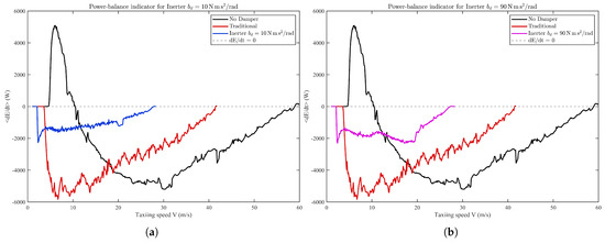
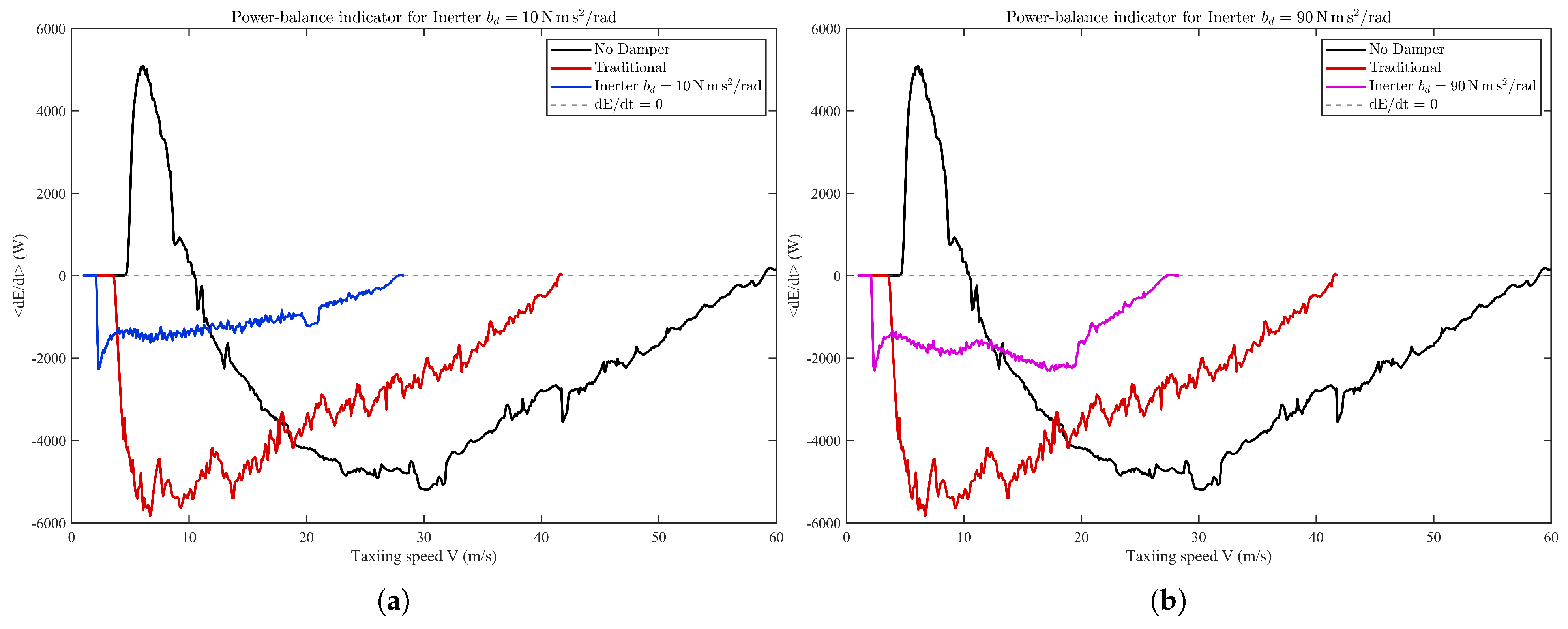
Figure 19 shows the variation in with V under different values. The results show that the no-shimmy-suppression-device condition exhibits a distinct positive power-input peak in the low-speed range, indicating that the primary structure itself has difficulty dissipating the self-excited energy introduced by tire slip-angle nonlinearity. Therefore, tire-induced torsional shimmy is prone to occur on the low-damping side. Under the conventional hydraulic shimmy damper and inerter-based shimmy suppression system conditions, the average power-balance indicator is negative within the shimmy speed range, indicating that both schemes can suppress the energy growth of the primary system and maintain the mechanical energy of the primary structure at a relatively low level. In comparison, of the inerter-based shimmy suppression system approaches zero at a lower speed. Compared with N·m·s2/rad, N·m·s2/rad maintains a more pronounced negative-power characteristic within the shimmy speed range, indicating that increasing the inertance coefficient helps enhance the energy-absorption capability of the branch.
Figure 19.
Average power-balance indicators under different inertance coefficients. (a) N·m·s2/rad; (b) N·m·s2/rad.
The above results show that the conventional hydraulic shimmy damper still has a certain shimmy suppression capability in the medium- and high-speed ranges, but its shimmy suppression performance in the low-speed range is insufficient. By contrast, the inerter-based shimmy suppression system further improves the energy attenuation characteristics in the low-speed range while maintaining shimmy suppression effectiveness in the medium- and high-speed ranges. From the perspective of energy transfer, the inerter-based system introduces an inertial moment associated with relative angular acceleration through and changes the dynamic impedance of the torsional channel, making it easier for strut torsional vibration energy to transfer to the shimmy suppression branch and eventually be dissipated through the damping element. This mechanism changes the energy-transfer path of the conventional hydraulic shimmy damper, which relies solely on viscous damping for energy dissipation, thereby widening the zero-shimmy region over the full speed range.
6. Conclusions
This paper establishes a nonlinear shimmy dynamic model of a nose landing gear equipped with a hydraulic shimmy damper and an inerter-based shimmy suppression system. Hopf bifurcation analysis, numerical continuation, and energy-evolution analysis are used to study the effects of shimmy damper parameters, structural parameters, and inerter parameters on the zero-shimmy region over the full speed range. The main conclusions are as follows:
- (1)
- The zero-shimmy region of the nose landing gear over the full speed range is jointly bounded by two types of boundaries on the low-damping and high-damping sides. The low-damping side is mainly governed by tire-induced torsional shimmy, whereas the high-damping side is mainly governed by lateral shimmy. Therefore, a larger shimmy damper damping is not necessarily safer. In conventional design, determining the damping parameter only by multiplying the critical damping for torsional shimmy by a safety factor may cause the design value to exceed the high-damping-side stability boundary and thereby induce new shimmy instability.
- (2)
- The shimmy damper damping has a distinct non-monotonic effect on shimmy stability. In the low-damping interval, increasing can effectively suppress tire-induced torsional shimmy. In the moderate-damping interval, the system can form a zero-shimmy region over the full speed range. As continues to increase, lateral shimmy or structural torsional shimmy may occur. When the shimmy damper stiffness increases, it simultaneously raises the low-damping-side boundary and lowers the high-damping-side boundary, thereby compressing the stable damping interval.
- (3)
- Structural parameters have different effects on the zero-shimmy region. The trail e mainly determines whether a zero-shimmy region exists, the strut torsional stiffness mainly regulates the high-damping-side stability boundary, and the strut rake angle mainly provides local correction of the boundary. Therefore, shimmy-stability design of a nose landing gear over the full speed range should adopt a hierarchical strategy in which trail is prioritized, strut stiffness is matched, rake angle is fine-tuned, and shimmy damper parameters are selected afterward.
- (4)
- The inerter can widen the stable damping interval limited by the hydraulic shimmy damper. Proper matching of the inertance coefficient and tuning stiffness can change the dynamic equivalent characteristics of the torsional channel, separate the tire-induced torsional shimmy boundary from the structural torsional shimmy boundary, and alleviate the restriction imposed by high-damping-side lateral shimmy on the damping upper limit. Under the studied conditions, the upper critical damping on the high-damping side can be increased from approximately 5800 N·m·s/rad for the conventional hydraulic shimmy damper to approximately 18,000 N·m·s/rad, an improvement of about 210%. This result indicates that the stable damping interval of the system is significantly widened, which can provide a larger design margin for nose landing gear shimmy damper parameter design and ground taxiing stability verification. Meanwhile, this improvement helps reduce the risk that uncertainties such as damping-parameter deviation, temperature variation, wear degradation, and changes in tire condition may drive the system into the high-damping-side instability region, and improves the stability robustness under shimmy damper selection, manufacturing tolerances, and service degradation conditions.
- (5)
- The energy-evolution results show that the inerter transfers strut torsional vibration energy to the inerter branch through inertial coupling and dissipates it through the damping element, thereby improving shimmy suppression capability in the low-speed range. In the low-speed range, the average energy of the inerter-based scheme is significantly lower than those of the conventional hydraulic shimmy damper and the no-shimmy suppression-device scheme. In the medium- and high-speed ranges, the inerter-based scheme still maintains effective shimmy suppression capability.
In summary, shimmy-stability design of a nose landing gear over the full speed range should simultaneously consider the low-damping-side torsional shimmy boundary and the high-damping-side lateral/structural shimmy boundary, and should determine the shimmy damper damping and stiffness on the basis of reasonable matching of structural parameters. The inerter-based shimmy suppression system can widen the high-damping-side stability margin without substantially changing the main structure of the landing gear, providing a feasible scheme for wide speed range shimmy suppression design of nose landing gear. In practical operation, factors such as airframe flexibility, shock–strut axial motion, longitudinal bending, joint clearance, Coulomb friction, hydraulic shimmy damper nonlinearity, runway unevenness, braking input, and parameter uncertainty may affect the quantitative locations of the stability boundaries. Future studies may combine bench tests, taxiing tests, or high-fidelity multibody dynamics simulations to further calibrate and validate the model parameters, stability boundaries, and shimmy suppression effect.
Author Contributions
Conceptualization, J.W. and H.L.; methodology, H.L. and J.Z.; software, J.Z. and H.Z.; validation, H.L., J.Z. and H.Z.; formal analysis, H.L. and J.Z.; investigation, J.Z. and H.Z.; resources, J.W. and S.Z.; data curation, J.Z. and H.Z.; writing—original draft preparation, J.W. and H.L.; writing—review and editing, J.W., H.L., S.Z. and S.L.; visualization, J.Z. and H.Z.; supervision, J.W. and S.Z.; project administration, J.W. All authors have read and agreed to the published version of the manuscript.
Funding
This research was funded by the Key Laboratory of Infrastructure Durability and Operation Safety in Airfield of CAAC, MK202402. This study was supported by the Joint Fund Program of the National Natural Science Foundation of China (Project No. U2433206, Project Title: Research on the Evolution Mechanism of Civil Airliner Re-landing Human-Machine Loop and Safety Risk Early Warning). We are grateful for the funding and support from these projects.
Data Availability Statement
Data are available from the corresponding author upon reasonable request.
Conflicts of Interest
The authors declare no conflicts of interest. The funders had no role in the design of the study; in the collection, analyses, or interpretation of data; in the writing of the manuscript; or in the decision to publish the results.
References
- Padmanabhan, M.A.; Dowell, E.H. Landing gear design/maintenance analysis for nonlinear shimmy. J. Aircr. 2015, 52, 1707–1710. [Google Scholar] [CrossRef] [Scilit]
- Thota, P.; Krauskopf, B.; Lowenberg, M. Multi-parameter bifurcation study of shimmy oscillations in a dual-wheel aircraft nose landing gear. Nonlinear Dyn. 2012, 70, 1675–1688. [Google Scholar] [CrossRef] [Scilit]
- Gao, X.; Lu, X.; Shan, Z. Shimmy characteristic analysis of dual-wheel nose landing gear considering strut axial displacement and longitudinal bending. J. Vib. Eng. 2025, 38, 517–528. [Google Scholar] [CrossRef]
- Romero, F.A. Sensitivity analysis for the shimmy dynamics of an airplane main landing gear. J. Appl. Nonlinear Dyn. 2021, 10, 513–529. [Google Scholar] [CrossRef] [Scilit]
- Jiang, Y.; Feng, G.; Liu, P.; Yuan, L.; Ding, J.; Jiang, B. Evaluation of joint clearance effects on the shimmy of nose landing gear. Aerospace 2023, 10, 722. [Google Scholar] [CrossRef] [Scilit]
- Xiao, X.; Zhao, Y.; Wu, H.; Zhu, G. Dynamic analysis of nose landing gear shimmy considering strut height and experiment on the test platform. Open J. Appl. Sci. 2025, 15, 919–937. [Google Scholar] [CrossRef]
- Ruan, S.; Zhang, M.; Nie, H. Research and analysis of Coulomb friction in landing gear shimmy. J. Aircr. 2024, 61, 1143–1154. [Google Scholar] [CrossRef] [Scilit]
- Ruan, S.; Zhang, M.; Yang, S.; Nie, H. Dynamics analysis of nose landing gear shimmy performance considering aircraft structural flexibility. Proc. Inst. Mech. Eng. Part G J. Aerosp. Eng. 2024, 239, 727–743. [Google Scholar] [CrossRef] [Scilit]
- Sivakumar, S.; Ganapathy Subramanian, L.R.; Giridharan, V. Shimmy vibration analysis of unmanned aircraft coupled with landing gears. J. Mech. Sci. Technol. 2024, 38, 137–147. [Google Scholar] [CrossRef] [Scilit]
- Cheng, L.; Cao, H.; Zhang, L. Two-parameter bifurcation analysis of an aircraft nose landing gear model. Nonlinear Dyn. 2021, 103, 367–381. [Google Scholar] [CrossRef] [Scilit]
- She, C.; Zhang, M.; Ge, Y.; Tang, L.; Yin, H.; Peng, G. Design and simulation analysis of an electromagnetic damper for reducing shimmy in electrically actuated nose wheel steering systems. Aerospace 2022, 9, 113. [Google Scholar] [CrossRef] [Scilit]
- Ruan, S.; Zhang, M.; Yang, S.; Hu, X.; Nie, H. Research on the stability and bifurcation characteristics of a landing gear shimming dynamics system. Aerospace 2024, 11, 104. [Google Scholar] [CrossRef] [Scilit]
- Zhang, Y.; Zhang, W.; Yue, Y. Hopf bifurcation analysis of a nose landing gear system of aircraft. Int. J. Bifurc. Chaos 2024, 34, 2450184. [Google Scholar] [CrossRef] [Scilit]
- Kou, M.; Zhang, J.; Lu, J.; Tan, S. A perturbation analysis of nonlinearity in landing-gear shimmy of a fleet aircraft. In Proceedings of the 32nd Congress of the International Council of the Aeronautical Sciences (ICAS 2020), Shanghai, China, 6–10 September 2021. Paper ICAS2020_0097. [Google Scholar]
- Wei, H.; Li, L.; Xu, Y.; Lei, S.; Wang, Y. Dynamic shimmy behavior and bifurcation analysis of driver–vehicle–road system. Meccanica 2023, 58, 1733–1748. [Google Scholar] [CrossRef] [Scilit]
- Wei, H.; Xu, Y.; Wang, X.; Li, L. Nonlinear shimmy and dynamic bifurcation in vehicle system with driver steering input. Proc. Inst. Mech. Eng. Part D J. Automob. Eng. 2024, 239, 1406–1416. [Google Scholar] [CrossRef] [Scilit]
- Wei, H.; Li, L.; Xu, Y.; Cheng, L.; Shi, B. Nonlinear shimmy behaviour of towed wheel subjected to unbalance excitation. Veh. Syst. Dyn. 2025, 871–889. [Google Scholar] [CrossRef] [Scilit]
- Wang, Y.; Jin, X.Y.; Yin, Y. Using nonlinear feedback control to improve aircraft nose landing gear shimmy performance. Meccanica 2022, 57, 2395–2411. [Google Scholar] [CrossRef] [Scilit]
- Du, X.; Xu, Y.; Liu, Q.; Liu, C.; Yue, X.; Liu, X.; Kurths, J. Shimmy dynamics in a dual-wheel nose landing gear with freeplay under stochastic wind disturbances. Nonlinear Dyn. 2024, 112, 2477–2499. [Google Scholar] [CrossRef] [Scilit]
- Guo, X.; Nan, T.; Chen, Y.; Zhang, W.; Cao, D. Aircraft nose landing gear shimmy with nonlinear tire models. Int. J. Bifurc. Chaos 2025, 35, 2550184. [Google Scholar] [CrossRef] [Scilit]
- Liu, C.; Liu, X.; Xu, Y. Landing gear shimmy analysis for a delayed tire model with transient modes. J. Aircr. 2026, 1–11. [Google Scholar] [CrossRef] [Scilit]
- Nan, T.; Guo, X.-Y.; Chen, Y.; Zhang, W.-X.; Lenci, S.; Zhang, L.-Y. Multi-parameter bifurcation analysis of shimmy in a new configuration dual-wheel nose landing gear. Nonlinear Dyn. 2026, 114, 513. [Google Scholar] [CrossRef] [Scilit]
- Hong, Y. Research on Shimmy Stability of Aircraft Nose Landing Gear Under Multi-Parameter Influence. Master’s Thesis, Nanjing University of Aeronautics and Astronautics, Nanjing, China, 2023. [Google Scholar] [CrossRef]
- Tamer, A.; Masarati, P. Sensitivity of Lyapunov exponents in design optimization of nonlinear dampers. J. Comput. Nonlinear Dyn. 2019, 14, 021002. [Google Scholar] [CrossRef] [Scilit]
- She, C.; Zhang, M.; Hinkkanen, M.; Ahmed, F.; Shi, J.; Liu, X. Damping coefficient characterization and experiment of an electromagnetic damper for shimmy reduction. IEEE/ASME Trans. Mechatron. 2025, 30, 2017–2027. [Google Scholar] [CrossRef] [Scilit]
- She, C.; Zhang, M.; Hinkkanen, M.; Yang, Y. An integrated design methodology for architecture solutions to shimmy reduction subsystems in all electric aircraft. IEEE Trans. Transp. Electrif. 2024, 10, 10428–10440. [Google Scholar] [CrossRef] [Scilit]
- Hong, Y.; Nie, H.; Zhang, M.; Wei, X. Shimmy analysis of nose landing gear considering nonlinear characteristics of shimmy damper. Adv. Aeronaut. Sci. Eng. 2023, 14, 109–118, 152. [Google Scholar] [CrossRef]
- Dong, L.; Chen, Z.; Sun, M.; Sun, Q. Phase compensation active disturbance rejection control for shimmy vibration with magnetorheological damper of aircraft. Expert Syst. Appl. 2023, 213, 119126. [Google Scholar] [CrossRef] [Scilit]
- Wang, Y.; Zhang, T.; Jin, X.; Yin, Y. Shimmy suppression of an aircraft nose landing gear using torsional nonlinear energy sink. J. Comput. Nonlinear Dyn. 2023, 18, 101002. [Google Scholar] [CrossRef] [Scilit]
- Wang, Y.; Zhang, T.; Yin, Y.; Wei, X. Reducing shimmy oscillation of a dual-wheel nose landing gear based on torsional nonlinear energy sink. Nonlinear Dyn. 2024, 112, 4027–4062. [Google Scholar] [CrossRef] [Scilit]
- Zhou, J.; Zhao, Y.; Xiao, X.; Liu, Y.; Zhou, L. Nose landing gear stability enhancement and shimmy suppression with a nonlinear energy sink. Chin. J. Solid Mech. 2024, 45, 759–775. [Google Scholar] [CrossRef]
- Zhou, J.; Zhao, Y.; Li, Q.; Wang, W. A multi-objective optimization of nose landing gear shimmy damper with nonlinear energy sink. J. Vib. Eng. 2026, 39, 20–30. [Google Scholar] [CrossRef]
- Li, Y.; Howcroft, C.; Neild, S.A.; Jiang, J.Z. Using continuation analysis to identify shimmy-suppression devices for an aircraft main landing gear. J. Sound Vib. 2017, 408, 234–251. [Google Scholar] [CrossRef] [Scilit]
- Zhang, S.Y.; Li, D.; Huang, R.; Sheng, X. Using an inerter-based device to suppress helicopter ground resonance. J. Mech. Sci. Technol. 2025, 39, 2479–2488. [Google Scholar] [CrossRef] [Scilit]
- He, X.; Chen, J.; Tang, D.; Peng, S.; Tang, B. Using an inerter-based suspension to reduce carbody flexible vibration and improve riding-comfort. SAE Int. J. Veh. Dyn. Stab. NVH 2023, 7, 137–151. [Google Scholar] [CrossRef] [Scilit]
- Smith, M.C. The inerter: A retrospective. Annu. Rev. Control Robot. Auton. Syst. 2020, 3, 361–391. [Google Scholar] [CrossRef] [Scilit]
- Wagg, D.J. A review of the mechanical inerter: Historical context, physical realisations and nonlinear applications. Nonlinear Dyn. 2021, 104, 13–34. [Google Scholar] [CrossRef] [Scilit]
- Ge, Z.; Wang, W. Modeling, testing, and characteristic analysis of a planetary flywheel inerter. Shock Vib. 2018, 2018, 2631539. [Google Scholar] [CrossRef] [Scilit]
- Sarkar, S.; Fitzgerald, B. Fluid inerter for optimal vibration control of floating offshore wind turbine towers. Eng. Struct. 2022, 266, 114558. [Google Scholar] [CrossRef] [Scilit]
- Abolghasemi, S.S.; Wierschem, N.E.; Knight, J.B. Vibration mitigation using an inerter-based isolation system. In Proceedings of the 2022 Conference Proceedings, Baltimore, ML, USA, 31 May–3 June 2022. [Google Scholar]

Disclaimer/Publisher’s Note: The statements, opinions and data contained in all publications are solely those of the individual author(s) and contributor(s) and not of MDPI and/or the editor(s). MDPI and/or the editor(s) disclaim responsibility for any injury to people or property resulting from any ideas, methods, instructions or products referred to in the content. |
© 2026 by the authors. Licensee MDPI, Basel, Switzerland. This article is an open access article distributed under the terms and conditions of the Creative Commons Attribution (CC BY) license.