


Abstract
CubeSat programs are often conducted under severe constraints in budget, personnel, schedule, and knowledge continuity, while still requiring sufficient verification to support mission success. This paper presents the verification, testing, on-orbit operation, and anomaly analysis of COSMIC, a 3U CubeSat jointly developed by Yonsei University, Unmanned Exploration Laboratory (UEL), and UZURO Tech Inc. in less than eleven months from project kickoff to launch. COSMIC adopted a protoflight model approach, prioritized commercial off-the-shelf components with flight heritage and prior laboratory experience, and concentrated limited resources on subsystem, FlatSat, system-level, environmental, communication, and scenario-based testing. The test program is reviewed against the subsequent on-orbit results to identify which verification activities contributed to anomaly prevention, fault isolation, and recovery. The results show that system-level integration testing, thermal vacuum cycle testing, and scenario testing were particularly effective in revealing interface, software, and deployment-related issues before launch and in supporting early orbit recovery. However, the mission also exposed limitations in recovery-logic verification, long-duration software testing, communication robustness, and independent reset paths. Based on these findings, practical recommendations are derived for resource-constrained CubeSat teams seeking to tailor verification activities without simply reducing test rigor.
1. Introduction
CubeSats have emerged as a key platform enabling universities, research institutions, and startups to access space, thanks to their low development costs and short development times. The extensive use of commercial off-the-shelf (COTS) components has significantly reduced development costs, contributing to an exponential increase in the number of CubeSat launches over the past decade [1].
Against this backdrop, Cho and Graziani [2] introduced the concept of the Lean Satellite. A Lean Satellite is developed through a non-traditional, risk-taking approach that aims to deliver value to stakeholders at minimum cost and in the shortest possible time. It is characterized by low-cost development, fast delivery, small team size, extensive use of non-space-qualified COTS components, and deliberate risk taking, and therefore represents a paradigm distinct from traditional satellite development practices. Cho and Graziani [2] further provide both quantitative and qualitative criteria for evaluating the degree to which a satellite aligns with the lean development philosophy, encompassing quantitative metrics such as total cost, delivery time, and team size, as well as qualitative factors such as risk-taking and risk-mitigation strategies.
The characteristics of lean satellites are particularly pronounced in the university development environment. However, the mission success rate of university-developed CubeSats remains notably low. According to Pradhan and Cho [1], the mission success rate of university-class satellites stands at approximately 50%, lower than the approximately 68% observed for government and private satellites. A particularly important finding is the counterintuitive trend that mission success rates for university satellites decline as development time increases, which is attributed to the progressive deterioration of knowledge transfer and budget margins as projects extend in duration. Based on these findings, Pradhan and Cho [1] proposed a target delivery time of two years or less, with an optimistic goal of one year or less. However, only 23% of university satellites in their dataset were delivered within two years, with those achieving delivery within one year accounting for approximately 5%.
Verification and testing are critical to mission success, and development teams have traditionally referred to standards such as European Cooperation for Space Standardization (ECSS) standard ECSS-E-ST-10-03C [3], National Aeronautics and Space Administration (NASA) standard NASA-STD-7002B [4], and the Goddard Space Flight Center (GSFC) General Environmental Verification Standard (GEVS), GSFC-STD-7000B [5]. However, these traditional standards were developed primarily for large spacecraft requiring high reliability and are not directly applicable to resource-constrained CubeSat development. The e-st@r-II mission illustrates this limitation, where full compliance with ECSS standards led to a verification process that was overly burdensome, without guaranteeing mission success [6].
In recognition of these limitations, standards more suited to CubeSat and lean satellite development have emerged. The European Space Agency (ESA) published the Tailored ECSS for in-orbit demonstration (IOD) CubeSats document, which provides a CubeSat-specific adaptation of ECSS requirements [7]. In addition, International Organization for Standardization (ISO) standards ISO 20991 [8] and ISO 19683 [9] were introduced to address small spacecraft requirements and design qualification and acceptance testing from a lean perspective. However, cases in which these standards were applied under actual, extreme resource-constrained conditions and the resulting decisions were analyzed against on-orbit operational outcomes remain scarce.
The 3U CubeSat COSMIC, which stands for COmmercial Space Mission In Cubesat, was jointly developed by Yonsei University, Unmanned Exploration Laboratory (UEL), and UZURO Tech Inc. and represents a direct example of such resource-constrained university CubeSat development. COSMIC satisfies the lean satellite criteria proposed by Cho and Graziani [2] in terms of total development cost, team size, delivery time, and extensive use of COTS components. The core development team consisted of twelve members, including a system engineer and subsystem leads who had prior experience in one or more satellite development projects. The other members were either first-time participants in satellite development or had limited experience in leading subsystem-level tasks. This mixed experience level is typical of university satellite development teams, where a small number of members with prior project experience work together with members who are new to satellite development. Despite these constraints, COSMIC achieved launch in less than eleven months from project kickoff, placing it among the approximately 5% of university-class satellites in the dataset of Pradhan and Cho [1] that achieved delivery within one year. The structural constraints characteristic of university satellite projects, including personnel turnover due to student graduation and restricted research budgets, were equally applicable to the COSMIC development process. COSMIC thus represents a rare case study in which the entire development process, from project kickoff to on-orbit operation, was completed under severe resource constraints.
This paper presents an analysis of the verification and testing approach adopted in COSMIC, examining which test items were selected and why, and how those decisions manifested in on-orbit operational outcomes. The testing approach is subsequently compared against ISO 19683 [9] to assess the extent to which it aligns with established small spacecraft verification standards. The findings aim to provide practical recommendations and guidelines for university CubeSat development teams operating under similar resource constraints.
The remainder of this paper is organized as follows. Section 2 describes the mission overview, development approach, and system configuration of COSMIC. Section 3 presents the implementation and results of the verification and testing program. Section 4 analyzes the on-orbit operational results and recovery process. Section 5 discusses the effectiveness of the selected verification activities, compares the test program with ISO 19683, analyzes major anomalies and lessons learned, and derives recommendations and guidelines. Section 6 presents the conclusions.
2. COSMIC Mission and Development
2.1. Mission Overview
COSMIC is a 3U CubeSat jointly developed by Yonsei University, Unmanned Exploration Laboratory (UEL), and UZURO Tech Inc. in the Republic of Korea, and was launched as a secondary payload aboard the NURI (Korea Space Launch Vehicle-II; KSLV-II) launch vehicle in its fourth flight. The primary mission objectives of COSMIC were to provide on-orbit verification of two commercially developed payloads: the Post-Mission Disposal (PMD) device developed by UZURO Tech Inc., referred to as UZU PMD, and the On-Board Computer (OBC) and Electronic Speed Controller (ESC) developed by UEL.
The UZU PMD is a propulsion payload intended to support an end-of-life deorbit demonstration. In addition, a dedicated camera for monitoring PMD operation, referred to as the UZU camera (UZU CAM), was integrated using a COTS product with flight heritage.
The UEL OBC and UEL ESC are components intended for integration into a lunar exploration rover currently under development by UEL. Their on-orbit verification mission aimed to validate their performance in the space environment prior to deployment in a lunar mission.
Within the joint development effort, Yonsei University was responsible for the bus system, while UEL and UZURO Tech Inc. developed their respective payloads concurrently with the bus development.
2.2. Development Approach
The development and verification approach adopted for COSMIC was determined based on three key factors.
First, due to the constrained development schedule and budget, it was not feasible to fabricate separate qualification and flight models and subject each to qualification-level and acceptance-level testing, respectively. Accordingly, COSMIC adopted a protoflight model (PFM) approach, in which the flight model underwent environmental testing at qualification-level test conditions with acceptance-level test durations. This represented a practical alternative that allowed both design qualification and flightworthiness to be demonstrated within a single model under the given resource constraints.
Second, compliance with the launch vehicle and deployer requirements of the NURI (KSLV-II) fourth launch served as the primary driver for defining the minimum scope of environmental testing. The mandatory environmental tests required for launch vehicle accommodation were random vibration testing and a thermal vacuum bakeout, both of which were conducted at PFM-level conditions. In addition, thermal-vacuum cycle testing, which was not mandated by the launch vehicle requirements, was performed to more comprehensively verify the satellite’s functional integrity under simulated space environmental conditions.
Third, in terms of COTS component selection, a different approach from that advocated by Cho and Graziani [2], which favors the extensive use of non-space-qualified COTS, was adopted. Instead, COTS components with flight heritage established through the laboratory’s previous satellite development programs were prioritized. This approach is consistent with the recommendation of the Tailored ECSS for IOD CubeSats document, which encourages the use of COTS modules that have already been qualified or possess flight heritage, and specifies that the verification program for CubeSats should be focused at the system level, given their high level of integration [7]. The selection of heritage-based COTS components was therefore a deliberate strategy to minimize the component-level verification burden and concentrate available resources on system-level integration and testing, consistent with the recommendation of Pradhan and Cho [1] that lean satellite development should prioritize system-level integration testing over component-level verification.
2.3. System Configuration
The bus system components of COSMIC are listed in Table 1. In selecting the components, COTS parts with flight heritage established through the laboratory’s previous satellite development projects, CANYVAL-X [10], CANYVAL-C [11], MIMAN [12], HYVRID [13], and VISION [14], were prioritized. The technology readiness level (TRL) and procurement lead time of each major bus component are also indicated in Table 1. In this study, the procurement lead time was defined as the period from quotation to actual delivery to the project team. The procurement lead times ranged from approximately 3 to 29 weeks, depending on the component.
Table 1.
COSMIC bus system configuration and procurement lead times of components.
As shown in Table 1, flight-heritage COTS were applied to all subsystems except the SMS, which was developed in-house based on the laboratory’s accumulated experience from previous satellite development programs. The procurement lead times were considered in establishing the integration and verification schedule, because the time available for flight-model integration and system-level testing depended on the delivery of key COTS components. Among the major COTS components, the UHF antenna had the longest procurement lead time, approximately 29 weeks, and therefore represented one of the long-lead items in the development schedule.
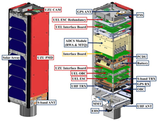
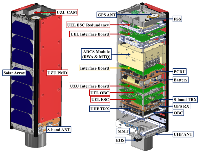
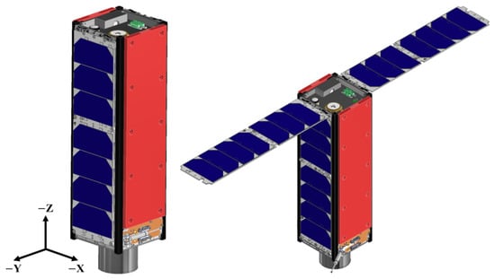
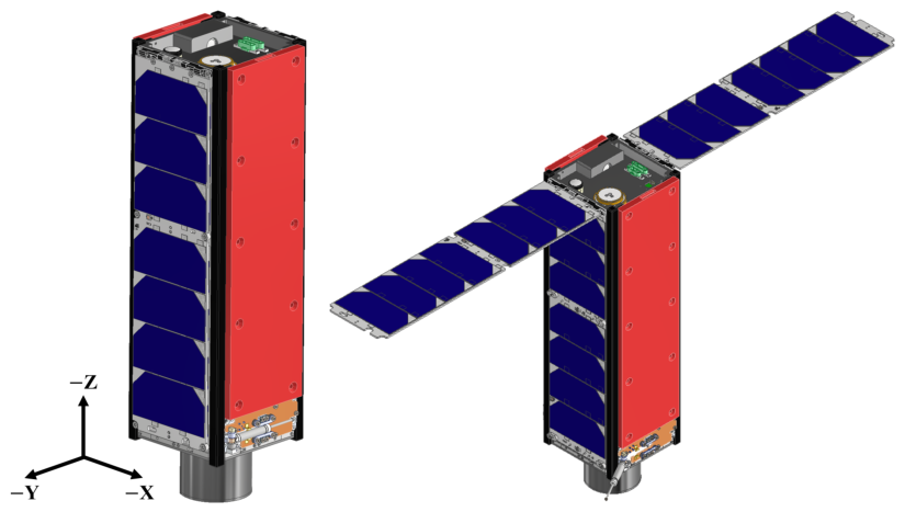
In addition to the flight units, one spare unit each of the OBC, PCDU, and battery was procured because these components were considered mission-critical for satellite operation. Spare S-band and UHF antennas were also procured to support multiple deployment tests during ground verification. Meanwhile, an Interface Board was developed in-house to accommodate the data and power interface requirements between subsystems. Given its lack of flight heritage as a newly developed component, thorough verification was conducted. The component layout and pre- and post-deployment configurations of the resulting COSMIC satellite are shown in Figure 1 and Figure 2, respectively.
Figure 1.
Component layout of COSMIC.
Figure 2.
Pre- and post-deployment configurations of COSMIC.
3. Verification and Testing: Implementation and Results
3.1. Test Program Overview
The verification and testing program for COSMIC was established in accordance with a development approach that prioritizes flight-heritage COTS components, with the aim of entering the integration phase as early as possible. For COTS components with sufficient verification heritage, individual component-level testing was minimized, with functional and performance verification conducted at the system integration level instead. For the in-house-developed Interface Board, a more conservative approach was taken, with individual functional verification performed at the component level prior to integration.
In accordance with this approach, the verification and testing program was carried out in the following sequence: subsystem and FlatSat testing, ground station communication testing, assembly, integration, and testing (AIT), and scenario testing.
The environmental test plan was established by considering both the launch vehicle requirements and the resource-constrained development environment. The mandatory tests required for launch vehicle and deployer accommodation are summarized in Table 2, which includes the deployer interface test, random vibration test, and thermal vacuum bakeout, all conducted at protoflight level. In addition, thermal-vacuum cycle testing, which was not mandated by the launch vehicle requirements, was performed twice to more comprehensively verify the satellite’s functional integrity under simulated space environmental conditions.
Table 2.
Mandatory environmental and interface tests required for accommodation on the NURI fourth launch vehicle.
3.2. Subsystem and FlatSat Test
The COSMIC bus system was configured primarily with COTS components, with flight heritage established through the laboratory’s previous satellite development programs. Accordingly, for components with sufficient heritage, individual component-level testing was minimized, and the integration phase was entered as early as possible, with functional and interface verification conducted at the system level.
For the in-house developed Interface Board, however, a more conservative approach was adopted. The Interface Board serves as the electrical intermediary between subsystems that do not support PC104 connections, providing power supply through harnesses and enabling data communication with the OBC. Given that the proper functioning of this board is directly linked to the operability of the connected components, continuity testing was performed at the component level to verify that there were no anomalies in the electrical connections, prior to verifying its operation in conjunction with the connected components.
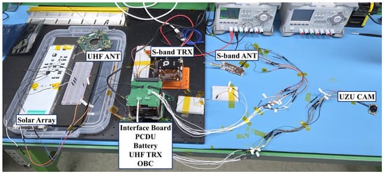
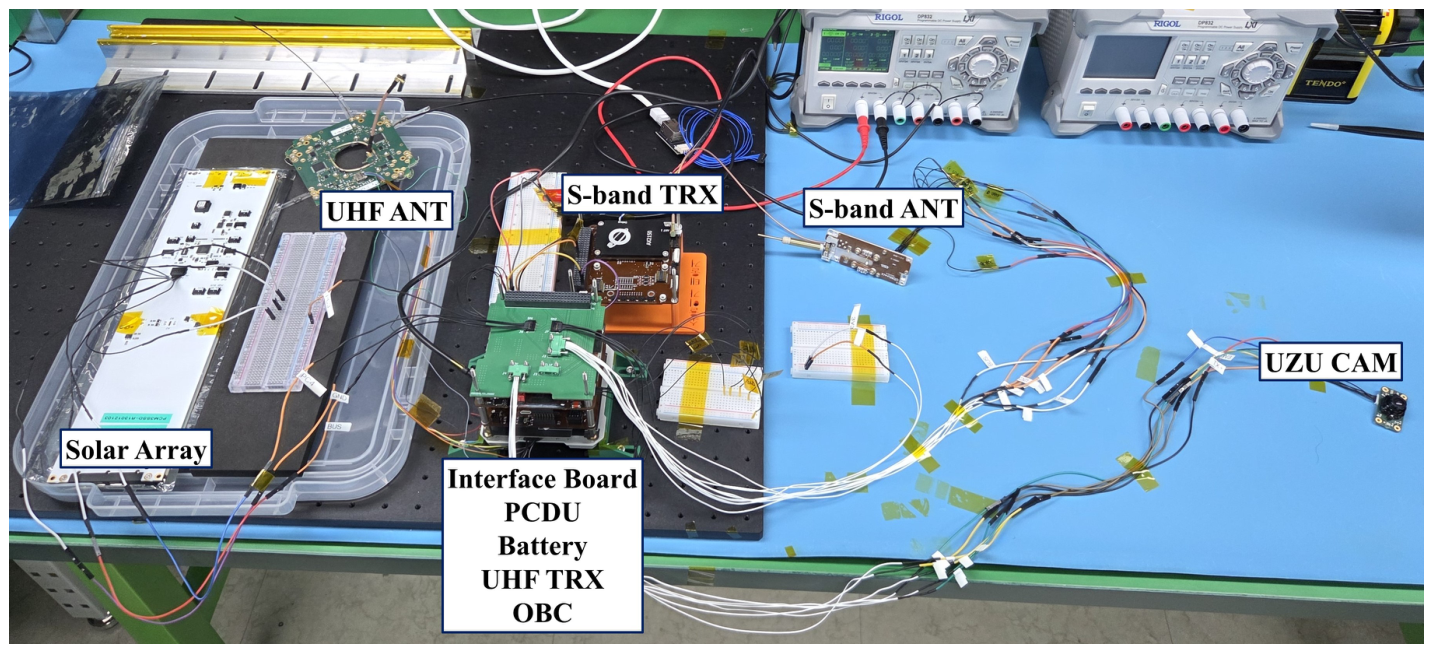
The primary testing activity conducted prior to AIT was FlatSat testing. In this test, some components were partially configured in a stacked configuration, while the remaining components were connected via harnesses, allowing comprehensive verification of power supply to each component, command execution in response to OBC commands, and corresponding responses and data-reception status. The FlatSat test configuration is shown in Figure 3, and the components included in the test, along with the verified functions, are summarized in Table 3. In summary, rather than investing time in component-level testing, COSMIC allocated relatively more time to the FlatSat test to verify system-level functionality and interfaces in advance, and to confirm that the flight model was ready to proceed to the AIT phase.
Figure 3.
FlatSat test configuration used to verify subsystem power, command, telemetry, and interface functions before full flight-model integration.
Table 3.
FlatSat test configuration and verified subsystem functions before assembly, integration, and testing (AIT).
3.3. Ground Station Communication Test
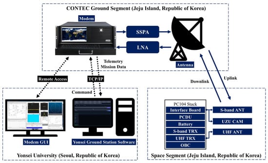
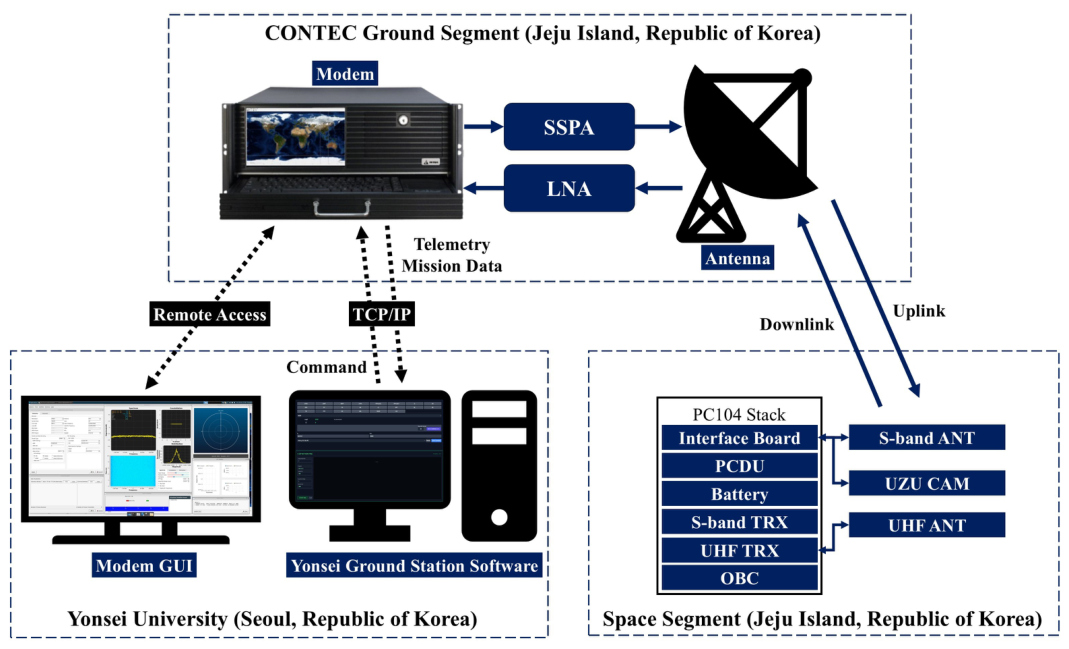
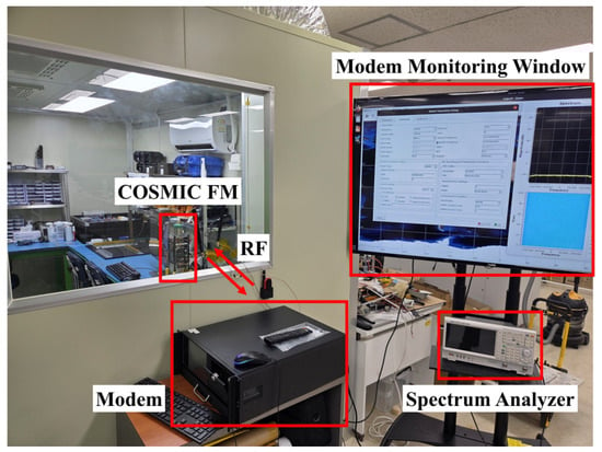
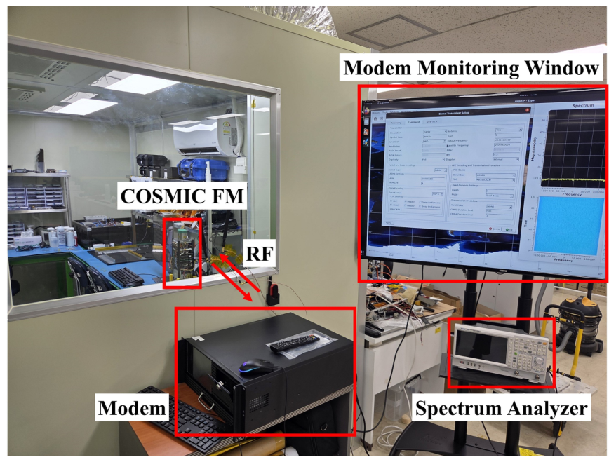
Ground station communication testing was conducted in parallel with subsystem and FlatSat testing to verify that communication between the satellite and ground station equipment was achievable prior to launch. In the COSMIC ground segment architecture, satellite operations were planned to be conducted from the mission control room at Yonsei University in Seoul, while the ground station antenna, modem, and associated radio-frequency (RF) equipment were installed at the CONTEC ground station facility in Jeju Island. Therefore, the test was designed to verify not only the RF communication chain between the satellite and the ground station equipment, but also the end-to-end operational configuration required for remote satellite operations. The test was conducted in two phases: an RF compatibility test and a far-field test.
3.3.1. RF Compatibility Test
The RF compatibility test was performed to verify that the COSMIC S-band and UHF transceivers could communicate normally with the ground station modem. The test was conducted at the ground station facility, where the satellite-side configuration consisted of the S-band and UHF transceivers and the OBC, while the ground station side consisted of the ground station modem and the Yonsei University ground station software. The satellite transceivers and the ground station modem were directly connected via RF cables.
This test verified that the RF physical-layer settings on both the satellite transceivers and the ground-station modem were consistent. In addition, uplink commands transmitted from the ground station software were correctly decoded by the OBC, and downlink data generated by the satellite-side configuration was correctly received and parsed by the ground station software. The TCP/IP packet structure used for remote communication between the Yonsei University ground station software and the ground station modem was also verified to confirm compatibility with the planned remote operation scheme. Through this test, the RF physical-layer settings, command and telemetry packet handling, and remote communication configuration were confirmed to function correctly within the ground-station communication chain.
3.3.2. Far-Field Test
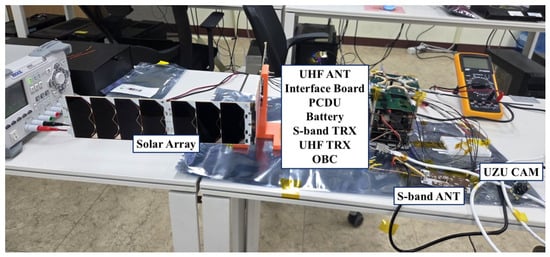
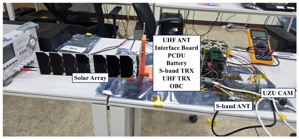
The far-field test was subsequently performed to verify wireless communication between the satellite and the ground station under conditions closer to the actual operational environment. The ground station is located in Sangdae-ri, Jeju Island, and the satellite-side configuration was installed at Geum-oreum, approximately 3.6 km from the ground station. The satellite-side configuration consisted of engineering model units, including the OBC, S-band transceiver, S-band antenna, UHF transceiver, UHF antenna, PCDU, battery, and UZU CAM. The overall configuration of the far-field communication test is shown in Figure 4.
Figure 4.
Far-field communication test configuration between the satellite-side engineering model setup at Geum-oreum and the CONTEC ground station in Jeju Island.
During the test, all satellite-side antennas were configured in their deployed state, and the satellite-side configuration was oriented so that the maximum gain direction of the antennas pointed toward the ground station antenna. The ground station antenna was also pointed toward the satellite-side installation. The Yonsei University ground station software was operated from the mission control room in Seoul and connected to the ground station modem in Jeju Island via TCP/IP, thereby replicating the planned remote operation configuration.
The test verified that the ground station could successfully receive and parse beacon transmissions from the satellite, and that the satellite could correctly respond to uplink status request commands. TCP/IP communication between the Yonsei University ground station software and the ground station modem was also confirmed to be functioning normally. The test demonstrated that both wireless communication between the satellite and the ground station and remote communication between the mission control room and the ground station operated correctly under far-field conditions.
3.4. Assembly, Integration, and Testing
3.4.1. Deployer Interface Test
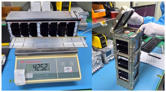
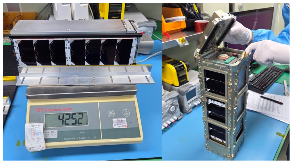
Upon completion of flight model assembly, a deployer interface test was conducted to verify that the integrated COSMIC satellite satisfied the dimensional and mass requirements of the 3U deployer. The test was performed in the laboratory clean room using the deployer provided by the manufacturer. The mass of the integrated satellite was measured at 4.252 kg, confirming compliance with the 3U CubeSat mass requirement of less than 6 kg. In addition, the integration and separation procedures of the satellite within the deployer were successfully demonstrated with no anomalies observed. The mass measurement and deployer integration test results are shown in Figure 5.
Figure 5.
Mass measurement and deployer interface verification of the fully assembled COSMIC flight model before launch accommodation.
3.4.2. Random Vibration Test
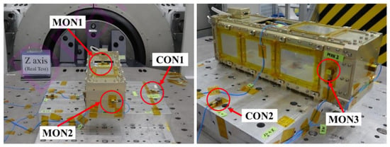
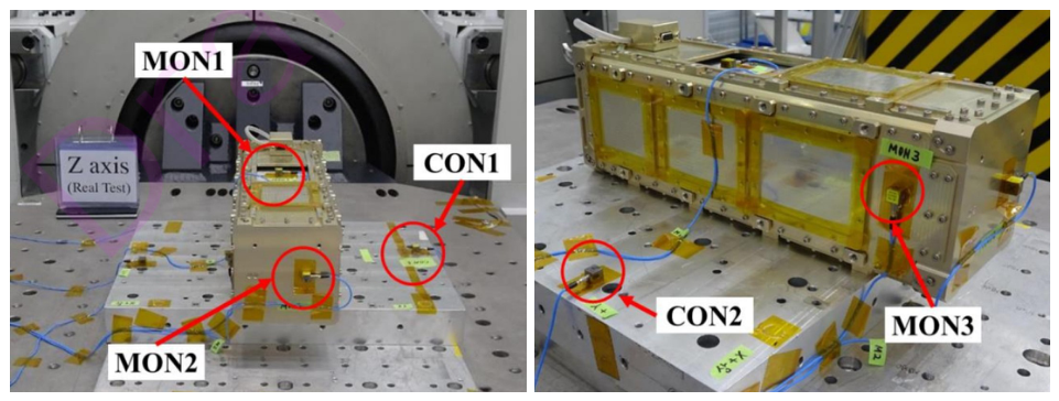
Random vibration testing is a mandatory environmental test required for accommodation aboard the NURI fourth launch vehicle. The COSMIC flight model underwent random vibration testing at the protoflight level at the Korea Aerospace Industries (KAI) facility, with the satellite integrated into the deployer prior to testing. The protoflight-level test conditions applied are presented in Table 4. The test was conducted with three objectives: visual inspection after each axis test to verify the absence of physical damage; resonance survey before and after each axis test to assess the first natural frequency shift; and OBC boot count check before and after the entire test sequence to confirm that no unintended power-on events occurred during testing. Five accelerometers were attached during the test: two on the test fixture (CON1, CON2), one on the satellite body (MON1), and two on the deployer (MON2, MON3), as shown in Figure 6.
Table 4.
Protoflight-level random vibration test conditions applied to COSMIC for NURI launch accommodation, including the power spectral density (PSD), overall level, and duration.
Figure 6.
Accelerometer placement during random vibration testing, including fixture, satellite-body, and deployer monitoring channels.
The first natural frequency shift measured at MON1, MON2, and MON3 remained within 10% across all three axes, as summarized in Table 5. Although no specific requirement for the first natural frequency shift was defined for the NURI fourth launch, the 10% acceptance criterion referenced from the SpaceX Rideshare Payload User’s Guide [15] was applied as a reference standard. The OBC boot count prior to testing was 11, and increased to 12 following the completion of the test, confirming that no unintended power-on events occurred during the test. Visual inspection revealed no anomalies, and a manual shake check confirmed that no internal loosening or rattling was present.
Table 5.
First natural frequency shifts measured before and after random vibration testing for each test axis and monitoring channel.
3.4.3. Thermal Vacuum Bakeout
Thermal vacuum bakeout is a mandatory environmental test required for accommodation aboard the NURI fourth launch vehicle. It was conducted at the Korea Aerospace Industries (KAI) facility at protoflight level, with the satellite powered off throughout the bakeout process, and the conditions are summarized in Table 6. The key requirement for this test was that the total mass loss (TML) must be less than 1%. The mass of COSMIC was measured at 4.242 kg prior to the test and 4.241 kg following the test, resulting in a TML of 1 g (0.024%), which satisfies the TML requirement of less than 1%.
Table 6.
Thermal vacuum bakeout conditions used to verify outgassing acceptability for launch vehicle accommodation.
3.4.4. Thermal Vacuum Cycle Test
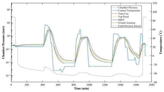
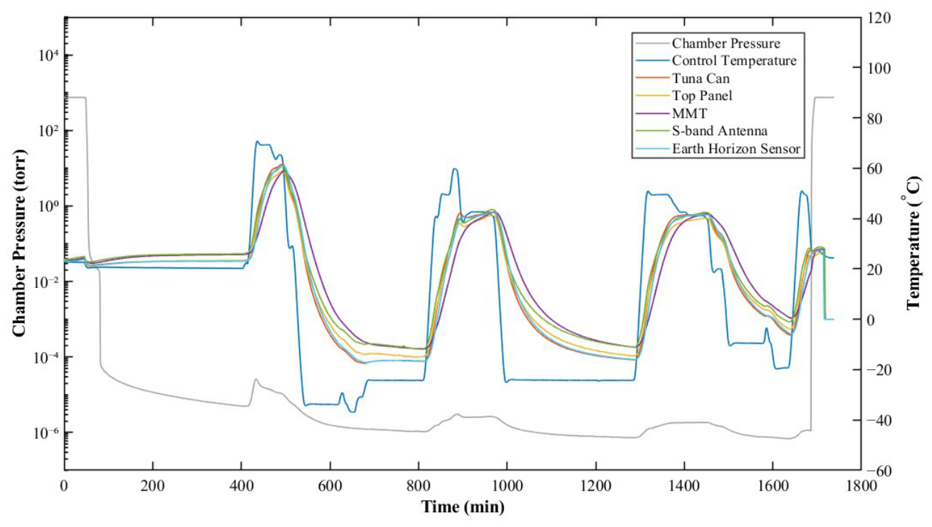
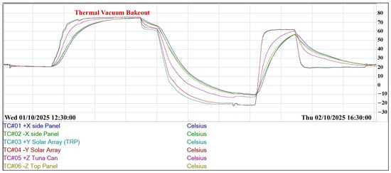
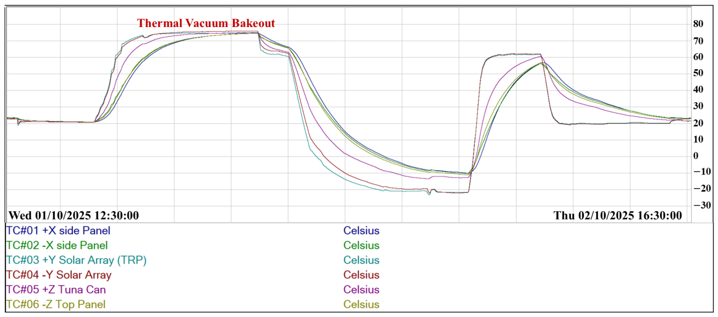
Thermal vacuum (TVAC) cycle testing was performed twice to more comprehensively verify the functional integrity of the satellite under simulated space environmental conditions. The first test was conducted at the Korea Reliability Technology Center (KRTC) facility, and the second test was conducted at the Korea Aerospace Industries (KAI) facility immediately following the thermal vacuum bakeout conducted in the same session. The test conditions for both tests are summarized in Table 7, and the corresponding temperature and pressure profiles are shown in Figure 7 and Figure 8, respectively.
Table 7.
Thermal-vacuum cycle test conditions for the first KRTC campaign and the second KAI campaign.
Figure 7.
Temperature and pressure profiles measured during the first thermal vacuum cycle test at KRTC.
Figure 8.
Temperature profile measured during the second thermal vacuum cycle test at KAI.
The functional verification activities performed during each test, along with their results, are summarized in Table 8 and Table 9. During the first thermal vacuum cycle test, a software-related anomaly was identified during beacon data collection, in which excessive OBC central processing unit (CPU) load prevented the software from operating normally. The anomaly was traced to an edge case in the CubeSat Space Protocol (CSP) library that was triggered under a specific port configuration when multiple hardware application tasks accessed the related communication logic simultaneously. At the KRTC test site, the issue was temporarily mitigated by introducing time separation between the relevant tasks. After the test campaign, the issue was resolved by modifying the port configuration to avoid the triggering condition.
Table 8.
Functional verification activities, observed anomalies, and corrective actions during the first thermal vacuum cycle test at KRTC.
Table 9.
Functional verification activities, observed anomalies, and corrective actions during the second thermal vacuum cycle test at KAI.
One of the significant findings of the second test was the measurement of deployment times for each deployable component under vacuum and cold state conditions. In particular, the two solar arrays required approximately 15 s and 40 s to deploy, respectively, with the latter representing the worst-case deployment time. This worst-case value of 40 s was subsequently adopted as the burn time for on-orbit solar array deployment operations. During the second test, the UHF antenna deployment in the +X and −X directions failed because the bottom panel pressed against the antenna cover prior to deployment. This was resolved by modifying the bottom panel design to provide clearance for the antenna cover, and successful deployment was confirmed under ambient conditions following the modification.
3.5. Scenario Test
Scenario testing was conducted to verify that the primary operational scenarios of COSMIC were executed correctly in accordance with the designed procedures. The tests focused on automatically executed operational modes, including the early orbit mode, UZURO Tech. PMD mode and communication emergency mode. The power emergency mode was also verified by intentionally lowering the battery voltage and confirming whether the PCDU correctly changed the battery state. In addition, single-command execution and the corresponding telemetry response were verified by confirming that ground commands were executed and the responses were received by the ground station modem. Finally, file downlink functionality in communication mode was also verified. The tests were performed in a near-field RF environment using actual ground station equipment set up in the laboratory.
Depending on the test objective, either the fully assembled flight model or an engineering model configuration was used. For the early orbit mode, an engineering model configuration was adopted to avoid consuming deployment actuations and the need for partial disassembly and reassembly of the satellite following each test. For the UZURO Tech. PMD mode, an engineering model configuration was used as the thruster could not actually be fired during ground testing. The communication emergency mode similarly required an engineering model configuration due to the UHF antenna deployment being part of the scenario. For the power emergency mode, an engineering model was used to prevent degradation of the flight battery, which would have required intentional deep discharge. The telecommand/telemetry (TC/TM) tests in standby mode and communication mode were conducted using the fully assembled flight model. The flight model (FM) and engineering model (EM) test configurations are shown in Figure 9 and Figure 10, respectively.
Figure 9.
Flight model configuration for scenario testing.
Figure 10.
Engineering model configuration for scenario testing.
The scenarios verified, and their key verification items are summarized in Table 10. The ADCS–OBC CAN communication failure recovery sequence, which was included in the early orbit mode scenario, was verified as a recovery-logic verification item. In this sequence, the OBC first attempts CAN communication with the ADCS to acquire the basic status information of the ADCS. If communication fails, the flight software executes the predefined sequence: a hard reset of the entire satellite power system, entry into ADCS boot mode, a 10 s wait period, execution of the ADCS ENABLE command, and subsequent CAN communication retries between the OBC and ADCS. The test confirmed that the designed recovery sequence, including the hard reset, GPIO command outputs for ADCS boot mode and ADCS ENABLE, and the subsequent communication retry, was executed in the intended order.
Table 10.
Scenario test summary.
The UZURO Tech. PMD mode was verified from the perspective of bus-side sequence execution. The test confirmed that the spacecraft executed the planned PMD electrical operation sequence, including switch-channel control, GPIO firing-command output, command-duration timing, and switch-channel termination. The switch-channel and GPIO outputs were verified using a multimeter, and the UZU CAM operation was directly confirmed to verify that the PMD monitoring sequence could be executed as designed.
All scenarios were successfully verified in accordance with the designed procedures. These tests confirmed that COSMIC’s major operational scenarios, including automatically executed modes, ground-command-based operations, telemetry reception, and file downlink operations, could be performed as designed.
4. On-Orbit Operation Results
4.1. Initial Contact and Satellite Health Check
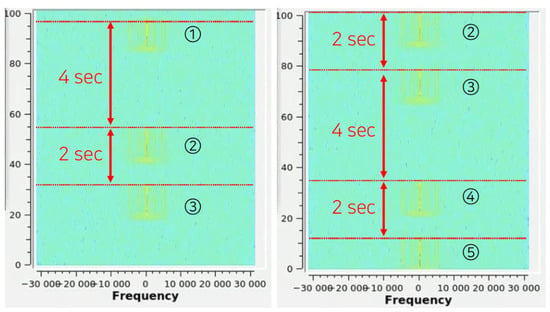
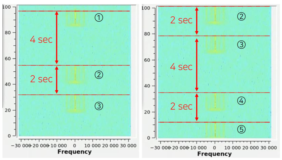
COSMIC was successfully launched aboard the NURI (KSLV-II) fourth launch vehicle and injected into a Sun-synchronous orbit with an altitude of 600 km, an inclination of 97.8°, and a mean local time of the ascending node (MLTAN) of 12:40 p.m. COSMIC was confirmed to have been ejected from the deployer. One day after ejection, the COSMIC-specific beacon transmission pattern, which had been verified during ground scenario testing, was received at the ground station modem, as shown in Figure 11. Although the received signal strength was insufficient for data parsing, the beacon pattern confirmed that the satellite had survived launch and was transmitting the signal.
Figure 11.
Beacon pattern received by the ground station modem during initial contact, used to confirm satellite activation and communication availability. The x-axis indicates the frequency offset from the configured center frequency in Hz, while the y-axis indicates elapsed time in seconds. Circled numbers denote the repeating COSMIC beacon sequence from 1 to 5.
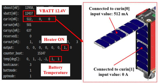
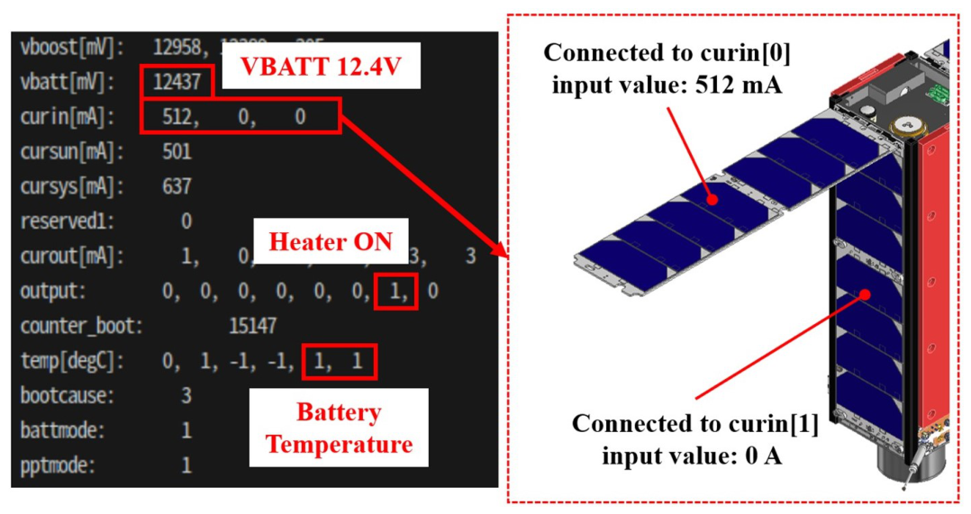
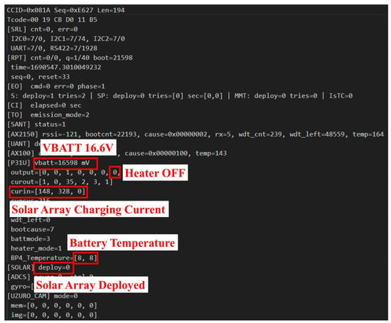
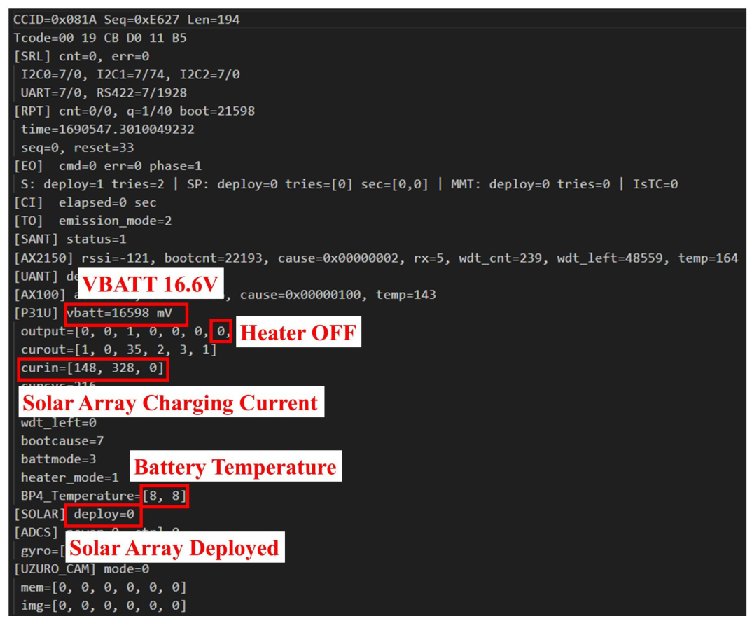
Subsequently, telemetry data were received and analyzed. Analysis of the EPS telemetry indicated that the battery voltage had dropped to approximately 12.4 V and the battery temperature was approximately 1 °C, with the battery heater found to be in operation. The battery heater was configured to activate at 0 °C and deactivate at 5 °C. These results deviated from the thermal analysis predictions, which had indicated that the battery temperature would be maintained in the range of approximately 6 to 7 °C, a range in which the battery heater should not have been activated. Furthermore, the absence of expected charging current on the solar array charging lines indicated that the solar arrays had not been deployed, as shown in Figure 12. The S-band antenna, however, was confirmed to have been successfully deployed based on the received telemetry.
Figure 12.
Electrical power system (EPS) telemetry indicating undeployed solar arrays through the absence of expected solar-array charging current.
4.2. Anomaly Analysis and Recovery
Based on the initial status analysis, the immediate mechanism behind the anomalous satellite state was investigated. Upon checking the satellite boot count, it was found that the value was continuously increasing at intervals of approximately 40 to 50 s, indicating that the satellite was repeatedly power-cycling. In the early orbit mode of COSMIC, a recovery sequence was implemented to address CAN communication failures with the ADCS, which included a procedure to re-apply satellite power. It was therefore determined that the ADCS CAN recovery sequence was being repeatedly triggered on-orbit without successfully restoring communication, resulting in periodic satellite reboots.
The repeated reboot behavior provided an explanation for the anomalous initial satellite state described in Section 4.1. The inability to sustain continuous satellite power prevented sufficient internal heat generation, leading to a drop in battery temperature and the activation of the battery heater. Furthermore, because the early orbit mode could not be completed normally due to repeated reboots, the solar array deployment sequence was never executed, leaving the solar arrays undeployed and the satellite unable to generate sufficient charging current, resulting in a continuous decrease in battery voltage.
To address this, a ground command was transmitted to terminate the ADCS recovery sequence, thereby preventing further reboots. Following this command, the boot count was confirmed to no longer increase, indicating that the repeated reboot behavior had ceased. However, since the solar arrays remained undeployed, the power issue persisted, with the satellite operating during dayside passes but powering off during eclipse.
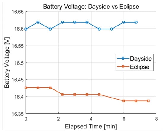
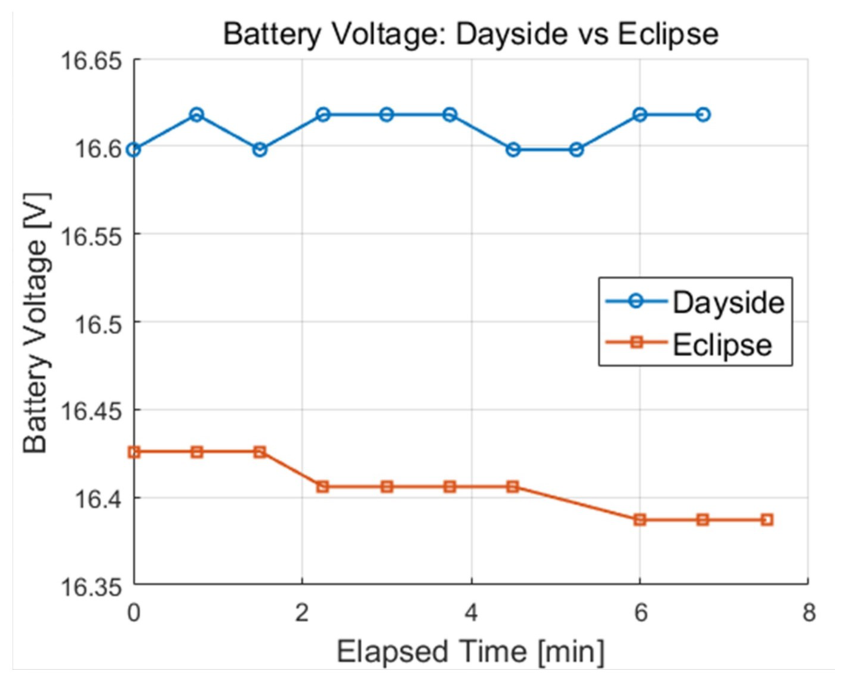
A solar array deployment command was subsequently transmitted with a burn time of 40 s, reflecting the worst-case deployment time confirmed during the thermal vacuum cycle test under cold state conditions. Following the command execution, the received beacon data and EPS telemetry confirmed that the satellite state had been successfully restored, as shown in Figure 13. Normal charging current was observed on the solar array charging lines; the solar arrays were indicated as deployed, and the battery temperature recovered to a trend consistent with the thermal analysis predictions. The battery voltage was subsequently maintained above approximately 16.5 V during dayside passes and above approximately 16.3 V during eclipse, as shown in Figure 14.
Figure 13.
Beacon data received after recovery, confirming restoration of the satellite state following solar-array deployment.
Figure 14.
Battery voltage trend during dayside and eclipse periods after recovery, showing restored charging behavior and stable power state.
4.3. Post-Recovery and Mission Operations
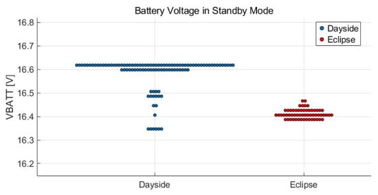
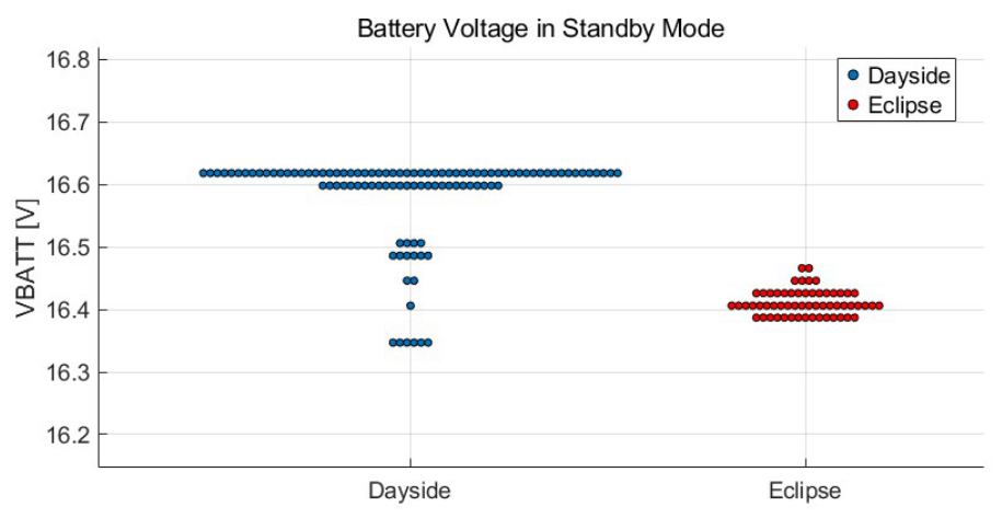
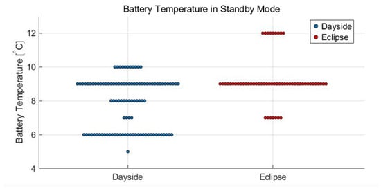
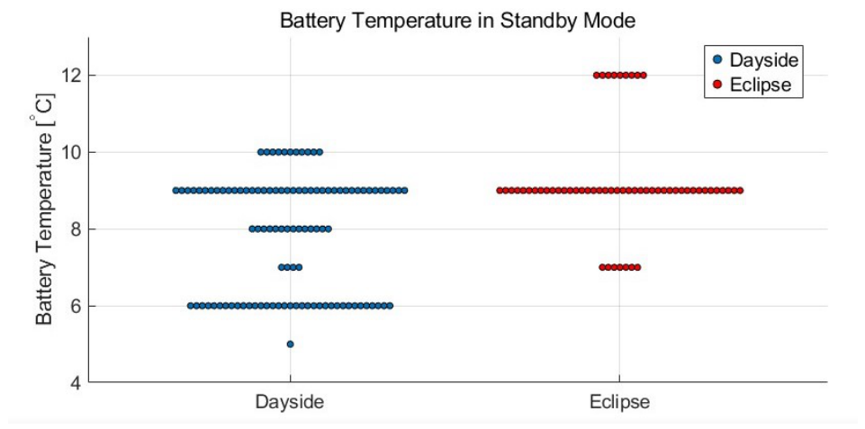
Following the successful recovery of the satellite, telemetry data were continuously collected to monitor the satellite’s state. Key parameters, including charging current, battery voltage, and battery temperature, were confirmed to be maintained within normal ranges, indicating that the power state of COSMIC had been fully restored. The battery voltage and temperature data collected during subsequent passes are shown in Figure 15 and Figure 16.
Figure 15.
Battery-voltage telemetry samples in standby mode after recovery, grouped by dayside and eclipse periods; each point represents one telemetry sample.
Figure 16.
Battery-temperature telemetry samples in standby mode after recovery, grouped by dayside and eclipse periods; each point represents one telemetry sample.
However, a subsequent anomaly was observed in which the OBC became unable to execute ground commands. While the commands transmitted from the ground station were confirmed to have been received by the transceiver, the OBC did not execute them, and no response was received, rendering further commanded operations temporarily impossible. Following an autonomous satellite reboot, the OBC recovered and was able to execute ground commands again. The UEL mission mode was subsequently performed without a separate commissioning phase, during which power was applied to the payloads, and data from the UEL OBC and UEL ESC were successfully received on the ground. Additional UEL mission operations were also performed, with relevant data successfully received.
The OBC command execution failure recurred during subsequent operations, after which further operations were temporarily not possible. The OBC subsequently recovered and returned to normal command execution state following an autonomous satellite reboot; however, a new anomaly was identified in which the OBC was unable to communicate with the PCDU. While the power input and output of the PCDU were confirmed to be functioning normally, PCDU telemetry could not be collected and commands could not be executed through the PCDU, preventing switch-channel operations. The satellite is currently in operation, and the key timeline of on-orbit operations is summarized in Table 11.
Table 11.
Key timeline of COSMIC on-orbit operations from initial beacon reception to anomaly recovery and mission operations.
5. Discussion
5.1. Test Effectiveness
The verification and testing activities conducted for COSMIC were retrospectively compared against the ISO 19683 protoflight test (PFT) criteria for small spacecraft to assess the extent to which the applied approach aligned with established verification practices for small spacecraft. The comparison is summarized in Table 12 and Table 13, which separately list the required and optional ISO 19683 PFT items and categorize each COSMIC verification status as performed, partially performed, not performed, analysis-based verification, or not applicable. Of the 24 system-level test items defined in ISO 19683 PFT, 9 items are classified as required and 15 items as optional. Among the required items, COSMIC fully performed 6 items, partially performed 3 items, and did not leave any required items unperformed. Among the optional items, COSMIC performed 2 items, did not perform 9 items, addressed 2 items through analysis-based verification, and 2 items were not applicable as the satellite did not include any pressurized components. In total, COSMIC performed, partially performed, or addressed through analysis 13 of the 24 system-level test items defined in ISO 19683 PFT, with the remaining items either not performed or not applicable. The effectiveness of the adopted verification approach was evaluated not only by the number of ISO 19683 items performed, but also by whether the selected tests contributed to anomaly detection, mitigation, or on-orbit recovery.
Table 12.
Required ISO 19683 PFT items and COSMIC verification status.
Table 13.
Optional ISO 19683 PFT items and COSMIC verification status.
Component-level testing was minimized in favor of early entry into the subsystem and FlatSat testing phase, allowing the development team to proceed to AIT within the constrained schedule. By prioritizing system-level integration testing, potential interface and functional issues were identified at an earlier stage, enabling timely resolution prior to AIT, including an ADCS–OBC CAN communication issue caused by an internal ADCS module CAN address scan error.
The mandatory environmental tests required by the launch vehicle—the deployer interface test, random vibration test, and thermal vacuum bakeout—were all performed at the protoflight level and successfully completed. These tests confirmed the structural compatibility and outgassing acceptability of COSMIC, thereby satisfying the launch vehicle accommodation requirements.
For optional items such as quasi-static load and thermal balance testing, structural and thermal analyses were conducted as alternatives. Optional environmental tests not required by the launch vehicle, such as shock, acoustic, and sinusoidal vibration testing, were not performed; the associated risk was managed through the use of COTS components with flight heritage.
Beyond the mandatory launch vehicle requirements, thermal vacuum cycle testing was performed as an additional activity and proved to be one of the most effective verification activities in the COSMIC program. Over the course of two thermal vacuum cycle tests, two anomalies were identified and resolved prior to launch. During the first test, excessive OBC CPU load during beacon collection was identified, revealing a software edge case that was subsequently addressed. During the second test, the UHF antenna deployment failure caused by bottom-panel interference was identified and resolved through hardware redesign. In addition, the worst-case solar array deployment time, approximately 40 s as measured under cold and vacuum conditions, was directly adopted as the burn time for the on-orbit solar array deployment command. As described in Section 4.2, this value proved critical in the successful recovery of the satellite following the initial orbit anomaly, demonstrating the practical value of thermal vacuum cycle testing even in a resource-constrained development environment.
Scenario testing was conducted to verify the primary operational sequences of COSMIC prior to launch. The early orbit mode scenario, which governs the most critical phase of satellite survival, was verified end-to-end, confirming that the deployment sequences and beacon transmission functioned correctly. Additional scenarios, including communication emergency mode, power emergency mode, TC/TM verification, and communication mode, were also verified end-to-end, collectively contributing to improved operational reliability. A limitation of the scenario testing was that extended-duration testing, such as a day-in-the-life test covering multiple orbital periods, was not performed. As a result, certain behavioral edge cases, particularly those related to recovery sequence termination and long-duration system behavior, remained insufficiently verified prior to launch, as further discussed in Section 5.2.
5.2. Anomaly Analysis and Lessons Learned
Based on the verification results and on-orbit outcomes discussed above, the major anomalies identified during the development, verification, and operation phases of COSMIC were analyzed from the perspective of observed failure mechanisms, direct or suspected causes, responses, and lessons learned. This section examines how the selected verification activities contributed to anomaly detection and recovery, and derives practical lessons for future resource-constrained CubeSat programs. Table 14 summarizes the anomalies and their identified or suspected immediate causes, while Table 15 summarizes the corresponding responses and lessons learned.
Table 14.
Summary of analyzed anomalies and identified or suspected immediate causes.
Table 15.
Summary of anomaly responses and lessons learned.
Several anomalies identified during the ground verification phase were resolved or mitigated prior to launch. These included interface, software, and mechanical deployment issues. In particular, the ADCS–OBC CAN communication issue (A-02), the CSP-library-related software edge case (A-03), and the UHF antenna deployment failure (A-04) were identified through system-level or environmental testing. These cases indicate that the emphasis on system-level testing was effective in revealing integration-related problems that may not have been identified through component-level verification alone. Additionally, the PCDU debug-line failure (A-01) showed the practical value of selectively procuring spare units for mission-critical COTS components. This anomaly was identified during the pre-assembly-and-integration (Pre-A&I) phase, before spacecraft assembly and integration, when the PCDU debug line failed to communicate. A continuity test confirmed that the ground (GND) pin of the debug line was not properly connected. Because a spare PCDU had been procured in advance, the faulty unit was replaced before A&I, thereby reducing the schedule impact of the hardware anomaly.
S-band communication degradation (A-07) was observed throughout operations, with telecommand (TC) reception limited to near-maximum-elevation passes and downlink signals too weak for data parsing. This result was inconsistent with the pre-launch S-band link budget, which indicated that both the uplink and downlink satisfied the minimum margin criterion. Because the satellite’s S-band antenna was an omnidirectional antenna, the analysis assumed an operational condition in which the spacecraft did not precisely point toward the ground station. The calculation reflected the 600 km operational orbit, actual S-band frequencies and data rates, satellite and ground station performance parameters, and relevant loss terms. In particular, a 3 dB polarization loss was included because the satellite S-band antenna used linear polarization, whereas the ground station antenna used circular polarization. Under these assumptions, the calculated link margins were 6.5 dB for the S-band downlink and 17.3 dB for the S-band uplink, both exceeding the minimum 6 dB design criterion. In addition, as described in Section 3.3.2, a pre-launch far-field communication test was performed, but it was limited to nominal conditions with the S-band antenna deployed and aligned toward its maximum-gain direction.
Therefore, the on-orbit degradation suggests that the actual S-band link performance was affected by factors that were not sufficiently represented in the nominal link budget or the pre-launch far-field test. The suspected causes include S-band antenna deployment failure, although the deployment status telemetry indicated successful deployment, an anomaly in the S-band transceiver, or incomplete ground station antenna tracking. Distinguishing between these candidate causes would have required more rigorous pre-launch far-field testing under degraded link conditions. Specifically, the far-field test should have incorporated path-loss attenuation representative of the actual orbital altitude, evaluated signal strength under varying ground-station pointing errors, and verified communication performance with the antenna in both deployed and undeployed configurations. Such comprehensive far-field characterization would enable direct comparison among the pre-launch link budget, ground test results, and on-orbit link performance, facilitating more definitive fault isolation. Although the underlying cause could not be definitively identified, the impact was mitigated during operations by lowering the baud rate and utilizing the UHF band as a redundant communication link.
The most significant on-orbit anomaly involved a cascading sequence of failures that resulted in an initial battery state inconsistent with pre-launch thermal analysis (A-08). The battery voltage was significantly lower than expected, and the battery temperature was below the predicted range, with the battery heater found to be actively operating. These conditions were the result of two coupled effects caused by repeated satellite reboots triggered by an ADCS recovery sequence infinite loop. First, the repeated reboots prevented the early orbit mode from completing normally, which in turn prevented solar array deployment. With the solar arrays undeployed, the satellite could not generate sufficient charging current, leading to a continuous decrease in battery voltage. Second, the repeated reboots suppressed internal heat generation from the satellite components, causing the battery temperature to fall below the heater activation threshold. The anomaly was resolved by terminating the ADCS recovery sequence via ground command and deploying the solar arrays using the worst-case burn time verified during the thermal vacuum cycle test, after which the battery voltage was successfully restored. This case demonstrated the importance of defining clear termination conditions and iteration limits for recovery sequences, and of conducting thorough systems engineering–flight software (SE–FSW) interface reviews prior to launch.
OBC command execution failures (A-09) occurred intermittently during on-orbit operations, with commands confirmed as received by the transceiver but not executed by the OBC. The suspected causes include a CAN bus anomaly or flight software deadlock, although the exact fault mechanism could not be determined. As no OBC-independent hard reset path was available, recovery relied entirely on autonomous satellite reboots. This highlighted the importance of conducting a day-in-the-life test using the final flight software to verify that no errors or faults emerge over extended operational periods, in addition to securing an OBC-independent hard reset path. Subsequently, an OBC–PCDU I2C communication failure (A-10) was identified, with PCDU status reads returning invalid values and commands not being executed. The suspected causes include a PCDU configuration reset or an I2C line anomaly, and no direct recovery path was available. These anomalies collectively highlighted the critical need for an OBC-independent hard reset mechanism and a redundant OBC–PCDU data interface in future missions.
Overall, the anomaly analysis shows that system-level testing and thermal vacuum cycle testing were effective in identifying several critical issues prior to launch and, in the case of the solar array deployment recovery, provided operational data that directly supported on-orbit recovery. At the same time, the on-orbit anomalies revealed limitations in the verification of recovery logic, long-duration system behavior, and OBC-independent recovery paths. These findings form the basis for the recommendations presented in Section 6.
5.3. Recommendations and Guidelines
Based on the analysis of the COSMIC verification approach and on-orbit operational outcomes, system-level integration testing, thermal vacuum cycle testing, and scenario testing contributed not only to the identification and mitigation of anomalies before launch but also to the recovery of the satellite during early orbit operations. In contrast, the anomalies observed on orbit revealed limitations in the verification of recovery logic, long-duration software behavior, communication robustness, and spacecraft power reset paths independent of the OBC.
Based on the COSMIC development and operational experience, the following recommendations are proposed for resource-constrained university CubeSat programs targeting delivery within approximately one year, as discussed in previous studies on university-class satellite development [1]. The recommendations are organized into three categories: development strategy, test items, and system architecture.
- Development strategy
- ○
- Prioritize COTS components with flight heritage and prior organizational experience. For resource-constrained CubeSat programs, the spacecraft should be configured, where possible, using COTS components with flight heritage. In particular, components that have already been integrated, tested, or operated by the development organization should be prioritized. This strategy reduces the need for extensive component-level verification and enables the team to enter the integration phase earlier.
- ○
- Selectively procure spare units for critical components. For mission-critical components, such as the OBC and PCDU, spare units should be procured when the budget allows. Spare units should also be considered for deployable components when repeated deployment testing is required during ground verification. Although cost must be carefully managed in resource-constrained programs, selective spare procurement can reduce schedule risk and support fault isolation during testing and operations. As noted by Pradhan and Cho [1], spare components should not be regarded as wasted expenditure.
- ○
- Minimize component-level testing for heritage-based COTS and allocate more effort to system-level testing. When flight-heritage COTS components are used, excessive component-level testing may not be the most effective use of limited development time. Instead, early transition to subsystem, FlatSat, and system-level integration testing is recommended. Such testing is essential for identifying interface, software, and operational anomalies that may not appear during isolated component-level verification.
- ○
- Maintain practical documentation of AIT, test results, and anomaly responses. Resource-constrained university CubeSat teams may not be able to maintain the same level of formal documentation as traditional satellite programs, because a small team is often responsible for design, integration, testing, troubleshooting, and operations under a compressed schedule. Nevertheless, AIT procedures, test results, anomalies, cause assessments, and corrective actions should be documented in a practical form. Even if the format is not elaborate, such documentation is essential for preserving development knowledge and transferring lessons learned to future missions.
- Test items
- ○
- Perform mandatory environmental testing at the level required by the launch vehicle and deployer. Under severe schedule and resource constraints, the minimum environmental test scope should first be defined based on launch vehicle and deployer accommodation requirements. In the COSMIC case, the deployer interface test, random vibration test, and thermal vacuum bakeout were performed at the required protoflight level to satisfy launch accommodation requirements.
- ○
- Include thermal vacuum cycle testing whenever feasible. Even when not required by the launch vehicle, thermal vacuum cycle testing should be included if schedule and resources permit. The COSMIC case showed that this test can reveal hardware, software, and deployment-related anomalies under hot, cold, and vacuum conditions. In particular, deployment-time data obtained under cold and vacuum conditions can provide worst-case operational parameters that cannot be reliably obtained under ambient conditions.
- ○
- Perform day-in-the-life testing using the final flight software on the flight model. The final flight software should be verified on the integrated flight model through extended-duration testing, such as a day-in-the-life test covering multiple orbital periods. This is important for identifying software edge cases, recovery-sequence issues, and long-duration interactions among subsystems that may not appear during short scenario-based tests.
- ○
- Perform far-field communication testing and validate the link budget under degraded conditions. Far-field testing should be conducted to verify end-to-end communication between the satellite and ground station. However, nominal far-field communication alone is not sufficient. Link budget validation should include realistic path-loss conditions, attenuator-based margin tests, antenna pointing errors, and worst-case antenna configurations such as undeployed or partially deployed antenna states. Signal strength should be measured and compared across configurations to validate both nominal and degraded communication performance.
- System architecture
- ○
- Secure hard-reset and recovery paths independent of nominal OBC command execution. CubeSat systems should include practical reset and recovery paths that do not rely solely on the OBC successfully receiving and executing commands. OBC-independent recovery paths, such as a verified watchdog or a direct ground-station–transceiver–PCDU reset path, should be considered and verified during system-level testing. This is particularly important because once the OBC becomes unable to execute commands, recovery options can become severely limited.
- ○
- Consider redundant interfaces for critical subsystem data paths. For critical subsystem interfaces, redundancy should be considered to improve recoverability from interface-level failures. In particular, the transceiver–OBC interface, which forms the first onboard data path for ground commands, and the OBC–PCDU interface, which is essential for spacecraft power control and survival, should be treated as critical data interfaces. Providing redundant communication paths for such interfaces can reduce the risk that a single interface anomaly prevents command execution, power control, or mission recovery.
These recommendations are not intended to reject or replace established verification standards. Instead, they provide practical lessons derived from the verification, testing, on-orbit operation, and anomaly analysis of COSMIC. In particular, the COSMIC case shows that verification tailoring for resource-constrained university CubeSat missions should not simply reduce the number of tests but should concentrate limited resources on activities that are directly connected to interface verification, operational robustness, anomaly recovery, and mission success.
6. Conclusions
This paper analyzed the verification and testing approach adopted for COSMIC, a resource-constrained university CubeSat developed and delivered within less than one year, and correlated the selected verification activities with the resulting on-orbit operational outcomes. COSMIC adopted a protoflight model approach, prioritized COTS components with flight heritage and prior organizational experience, and concentrated limited resources on system-level integration, environmental testing, communication testing, and scenario-based verification.
The results show that system-level integration testing, thermal vacuum cycle testing, and scenario testing were particularly effective in identifying and mitigating anomalies before launch. Thermal vacuum cycle testing revealed hardware, software, and deployment-related issues under hot, cold, and vacuum conditions, and the deployment time measured under cold and vacuum conditions was directly used to define the on-orbit solar array deployment command. Scenario testing also contributed to verifying early-orbit operations, emergency communication procedures, and power recovery sequences. These results demonstrate that selected ground verification activities can directly support anomaly response and recovery during early orbit operations.
At the same time, the on-orbit anomalies revealed limitations in the COSMIC verification approach. The OBC command execution failure, OBC–PCDU I2C communication failure, and S-band communication degradation showed that short-duration scenario tests and nominal communication tests were not sufficient to identify all operational risks. In particular, the absence of multi-day day-in-the-life testing using the final flight software limited the ability to detect long-duration software issues, such as flight software deadlock, time-dependent anomalies, or repeated recovery-sequence behavior. The on-orbit results also showed the need to verify autonomous fault management logic under persistent failure conditions and to secure recovery paths independent of nominal OBC command execution.
The COSMIC case also shows that a development and verification strategy based on flight-heritage COTS components and prior organizational experience has both advantages and limitations. For resource-constrained CubeSat programs, the use of heritage-based components can reduce the burden of component selection and verification, allowing limited resources to be concentrated on system-level integration and testing. However, this approach may also inherit architectural limitations and system-level constraints from previous configurations. In the COSMIC case, the on-orbit anomalies indicated that the system architecture could be improved by incorporating an OBC-independent spacecraft power reset path and redundant data interfaces between the OBC and PCDU.
Therefore, the effective use of heritage-based components and previous development experience requires more than simply reusing proven configurations. After each mission, anomalies, operational responses, corrective actions, and implications for future design and verification should be systematically analyzed and reflected in subsequent missions. In this study, the major anomalies observed during the development, verification, and on-orbit operation of COSMIC were organized and analyzed in terms of possible causes, responses, and lessons learned. Based on this analysis, practical recommendations were derived for future university CubeSat missions, including long-duration flight software verification, autonomous fault management with clear termination conditions, redundant critical data interfaces, OBC-independent reset paths, realistic communication testing, and practical documentation of AIT and anomaly responses.
Future work should extend this case-study-based analysis to follow-on CubeSats developed by the same laboratory or to CubeSats developed under similar resource constraints. Since this study is based on a single CubeSat mission, a comparative analysis with additional university CubeSat missions would help improve the generalizability of the proposed recommendations. In particular, future studies should further clarify the relationship between selected verification activities and on-orbit outcomes, with emphasis on long-duration flight software verification, autonomous fault management under persistent failure conditions, realistic communication testing, and recovery-oriented system architecture.
The COSMIC case provides an empirical example of how limited resources can be allocated to verification and testing activities in a resource-constrained CubeSat program, and which verification items can be directly connected to on-orbit operational outcomes. The analysis and recommendations presented in this paper are expected to support future CubeSat teams operating under similar development constraints in tailoring their verification strategies and improving the likelihood of mission success.
Author Contributions
Conceptualization, D.P., Y.E., D.-E.K. and S.-Y.P.; methodology, D.P. and D.-E.K.; validation, D.P.; formal analysis, D.P.; investigation, D.P., D.J., J.C. and H.K.; data curation, D.P.; writing—original draft preparation, D.P.; writing—review and editing, D.P. and Y.E.; visualization, D.P.; supervision, Y.E. and S.-Y.P.; project administration, Y.E.; funding acquisition, Y.E. All authors have read and agreed to the published version of the manuscript.
Funding
The development of COSMIC was funded by UZURO Tech Inc. and UEL.
Data Availability Statement
The data presented in this study are available from the corresponding author upon reasonable request. Some data are not publicly available due to confidentiality and mission-related restrictions.
Acknowledgments
This CubeSat work was supported by Unmanned Exploration Laboratory (UEL) and UZURO Tech Inc. The authors gratefully acknowledge the financial support provided by UZURO Tech Inc. and the Unmanned Exploration Laboratory (UEL), as well as the contributions of the CubeSat team at Yonsei University.
Conflicts of Interest
The authors declare that this study received funding from UZURO Tech Inc. and Unmanned Exploration Laboratory (UEL). The funders were not involved in the study design, collection, analysis, interpretation of data, the writing of this article or the decision to submit it for publication.
Abbreviations
| ADCS | Attitude Determination and Control System |
| AIT | Assembly, Integration, and Testing |
| ANT | Antenna |
| CAD | Computer-Aided Design |
| CAM | Camera |
| CAN | Controller Area Network |
| CNDH | Command and Data Handling |
| COMS | Communication Subsystem |
| COSMIC | COmmercial Space Mission In Cubesat |
| COTS | Commercial Off-the-Shelf |
| CPU | Central Processing Unit |
| CSP | CubeSat Space Protocol |
| CSS | Coarse Sun Sensor |
| ECSS | European Cooperation for Space Standardization |
| EHS | Earth Horizon Sensor |
| EM | Engineering Model |
| EMC | Electromagnetic Compatibility |
| EPS | Electrical Power System |
| ESA | European Space Agency |
| ESC | Electronic Speed Controller |
| FM | Flight Model |
| FSS | Fine Sun Sensor |
| FSW | Flight Software |
| GEVS | General Environmental Verification Standard |
| GNC | Guidance, Navigation, and Control |
| GND | Ground |
| GPIO | General-Purpose Input/Output |
| GPS | Global Positioning System |
| GSFC | Goddard Space Flight Center |
| HAN | Hydroxylammonium Nitrate |
| I2C | Inter-Integrated Circuit |
| IOD | In-Orbit Demonstration |
| ISO | International Organization for Standardization |
| KAI | Korea Aerospace Industries |
| KRTC | Korea Reliability Technology Center |
| KSLV-II | Korea Space Launch Vehicle-II |
| MLTAN | Mean Local Time of the Ascending Node |
| MMT | Magnetometer |
| MTQ | Magnetorquer |
| NASA | National Aeronautics and Space Administration |
| OBC | On-Board Computer |
| PCDU | Power Conditioning and Distribution Unit |
| PFM | Protoflight Model |
| PFT | Protoflight Test |
| PMD | Post-Mission Disposal |
| PSD | Power Spectral Density |
| RF | Radio Frequency |
| RS-422 | Recommended Standard 422 |
| RWA | Reaction Wheel Assembly |
| RX | Receiver |
| SE | Systems Engineer |
| SEE | Single Event Effects |
| SMS | Structure and Mechanism Subsystem |
| TC | Telecommand |
| TCP/IP | Transmission Control Protocol/Internet Protocol |
| TC/TM | Telecommand/Telemetry |
| TID | Total Ionizing Dose |
| TML | Total Mass Loss |
| TRL | Technology Readiness Level |
| TRX | Transceiver |
| TVAC | Thermal Vacuum |
| UEL | Unmanned Exploration Laboratory |
| UHF | Ultra-High Frequency |
| UZU | UZURO Tech Inc. |
References
- Pradhan, K.K.; Cho, M. Shortening of Delivery Time for University-Class Lean Satellites. J. Small Satell. 2020, 9, 881–896. [Google Scholar]
- Cho, M.; Graziani, F. Definitions and Requirements of Small Satellites Seeking Low-Cost and Fast-Delivery; IAA: Paris, France, 2017. [Google Scholar]
- ECSS-E-ST-10-03C Rev.1; Space Engineering—Testing. ESA-ESTEC: Noordwijk, The Netherlands, 2022.
- NASA-STD-7002B; Payload Test Requirements. NASA: Washington, DC, USA, 2023.
- GSFC-STD-7000B; General Environmental Verification Standard (GEVS) for GSFC Flight Programs and Projects. NASA GSFC: Greenbelt, MD, USA, 2021.
- Corpino, S.; Stesina, F. Investigation of a CubeSat in Orbit Anomaly through Verification on Ground. Aerospace 2020, 7, 38. [Google Scholar] [CrossRef] [Scilit]
- European Space Agency. Tailored ECSS Engineering Standards for In-Orbit Demonstration CubeSat Projects; Issue 1, Rev. 3; ESA: Noordwijk, The Netherlands, 2016. [Google Scholar]
- ISO 20991:2025; Space Systems—Requirements for Small Spacecraft. ISO: Geneva, Switzerland, 2025.
- ISO 19683:2026; Space Systems—Design Qualification and Acceptance Tests of Small Spacecraft and Units. ISO: Geneva, Switzerland, 2026.
- Park, J.-P.; Park, S.-Y.; Song, Y.B.; Kim, G.-N.; Lee, K.; Oh, H.J.; Yim, J.-C.; Lee, E.; Hwang, S.-H.; Kim, S.; et al. CubeSat Development for CANYVAL-X Mission. In Proceedings of the SpaceOps 2016 Conference, Daejeon, Republic of Korea, 16–20 May 2016. [Google Scholar] [CrossRef] [Scilit]
- Kim, G.-N.; Park, S.-Y.; Lee, T.; Kang, D.-E.; Jeon, S.; Son, J.; Kim, N.; Park, Y.-K.; Song, Y. Development of CubeSat Systems in Formation Flying for the Solar Science Demonstration: The CANYVAL-C Mission. Adv. Space Res. 2021, 68, 4434–4455. [Google Scholar] [CrossRef] [Scilit]
- Jin, S.-M. Detailed Design and Analysis of a CubeSat for Fine Dust Observation Mission. Master’s Thesis, Yonsei University, Seoul, Republic of Korea, 2021. (In Korean) [Google Scholar]
- Won, S.-Y. HYVRID CubeSat Critical Design for Next Generation Satellite Laser Ranging Verification. Master’s Thesis, Yonsei University, Seoul, Republic of Korea, 2024. (In Korean) [Google Scholar]
- Kim, G.-N.; Park, S.-Y.; Seong, S.; Lee, J.; Choi, S.; Kim, Y.-E.; Ryu, H.-G.; Lee, S.; Choi, J.-Y.; Han, S.-K. The VISION–Concept of Laser Crosslink Systems Using Nanosatellites in Formation Flying. Acta Astronaut. 2023, 211, 877–897. [Google Scholar] [CrossRef] [Scilit]
- Space Exploration Technologies Corp. Rideshare Payload User’s Guide; Version 10; Space Exploration Technologies Corp.: Hawthorne, CA, USA, 2024. [Google Scholar]

Disclaimer/Publisher’s Note: The statements, opinions and data contained in all publications are solely those of the individual author(s) and contributor(s) and not of MDPI and/or the editor(s). MDPI and/or the editor(s) disclaim responsibility for any injury to people or property resulting from any ideas, methods, instructions or products referred to in the content. |
© 2026 by the authors. Licensee MDPI, Basel, Switzerland. This article is an open access article distributed under the terms and conditions of the Creative Commons Attribution (CC BY) license.