


Abstract
Solar radiation can induce circumferential temperature gradients and thermoelastic bending moments in lightweight spacecraft appendages. For spinning spacecraft, this thermal excitation is periodically modulated by spin motion and may amplify flexible response when the modulation frequency approaches a structural frequency. This study investigates the spin-modulated thermoelastic response of a spacecraft with a circular thin-walled flexible appendage under attitude-dependent solar radiation. A reduced-order rigid-flexible-thermal model is formulated by coupling rigid-body attitude motion, assumed-mode appendage deformation, first-harmonic circumferential temperature perturbations, and the resulting generalised thermoelastic bending moment. Long-time simulations, spin-period response sampling, degraded-model comparisons and modal energy/work diagnostics are used to identify the dominant response mechanism. The results show that the post-transient flexible response is governed mainly by spin rate, while the initial solar-incidence angle modifies the local response classification in the sampled high-spin region. Representative high-spin loss-of-admissibility cases lie near the first bending-frequency region, where the retained structural energy and positive thermoelastic work input are concentrated mainly in the first bending mode. Removing deformation-dependent solar-incidence feedback does not eliminate these cases, whereas suppressing thermoelastic bending does. Thus, spin-modulated thermoelastic bending is the essential pathway by which attitude-dependent solar radiation amplifies appendage response.
1. Introduction
Modern spacecraft increasingly employ lightweight flexible appendages, such as deployable booms, hoop-truss antennas, solar-array supports, phased-array structures, flexible tethers and large spaceborne antenna systems. These appendages provide essential mission functions, but their low-frequency elastic modes may interact with the attitude motion of the central spacecraft body and affect vibration characteristics, pointing accuracy and operational stability. This interaction is especially important for spinning or spin-stabilised spacecraft, because the spin motion continuously changes the orientation of the appendage relative to the inertial environment and to external excitation sources. Shen and Hu [1] investigated the thermally induced dynamics of a spinning spacecraft with an axial flexible boom and showed that the thermal response of a spinning boom and the attitude motion of the rigid hub should be treated as a coupled rigid-flexible problem. Rigid-flexible coupled dynamics and control have also been studied for spacecraft with hoop-truss antennas subjected to thermally induced vibration and attitude motion [2]. More general studies on flexible cantilever beams connected to central rigid bodies, tethered spacecraft, smart rigid-flexible-thermo-electrical spacecraft, spacecraft micro-vibration suppression and long flexible booms on spinning heliospheric spacecraft further demonstrate that appendage flexibility can influence vibration characteristics, attitude response, pointing performance and control effectiveness [3,4,5,6,7]. Recent studies on deployable flexible appendages and large-flexible-appendage spacecraft also show that appendage stiffness, deployment state and large-angle attitude motion can significantly affect attitude–vibration coupling [8,9]. These studies indicate that a flexible appendage should not be regarded as a passive structural attachment; instead, its deformation may exchange momentum with the rigid hub and reshape the coupled attitude-flexible response of the spacecraft system.
The orbital thermal environment introduces another important coupling mechanism. Spacecraft appendages are exposed to direct solar radiation, eclipse transitions, Earth-reflected radiation and radiative cooling. Non-uniform illumination may generate temperature gradients, thermal stresses and thermoelastic bending moments. For thin-walled booms, tubular appendages and solar-array-like structures, circumferential or through-thickness temperature variation is especially important because it can produce bending deformation even in the absence of mechanical contact loads. Thornton and Kim [10] developed a classical analytical model for thermally induced bending vibrations of a flexible rolled-up solar array. Their work showed that sudden external heating can generate both quasistatic bending and superimposed transient vibration, and that deformation-heating coupling may lead to thermal flutter under certain combinations of thermal response time, structural response time, solar inclination angle and damping. More recent studies have extended this viewpoint to thermo-mechanical jitter in slender space structures [11], composite thin-walled booms on satellites [12], sun-facing beams under gravity-gradient and solar-thermal effects [13], thin-walled tubes in thermal environments [14], flexible spacecraft solar arrays under thermally induced flutter during penumbra transitions [15], thermoelastic temperature-shock problems [16], thermo-flexible composite laminated plates [17], flexible deploying booms under solar thermal shock [18], and small spacecraft with flexible elements subjected to temperature-shock perturbations [19]. Thermal-structural analysis of flexible spacecraft with single or double solar panels further shows that attitude motion, structural deformation and time-varying thermal loading may need to be evaluated as a coupled problem when thermally induced deformation and vibration are of concern [20]. These works collectively show that solar heating and thermal shock can act as dynamic excitation mechanisms, not merely as sources of quasi-static temperature fields.
Because attitude motion, flexible vibration and thermal deformation can influence one another, rigid-flexible-thermal coupled modelling has become an important tool for analysing large and lightweight spacecraft. At the structural level, thermomechanical formulations for thin-walled beam structures considering radiation dissipation provide useful foundations for modelling heat transfer and thermal deformation in slender space structures [21]. At the spacecraft-system level, rigid-flexible-thermal coupling has been developed for ultra-large phased-array antennas [22], hub-multiplate systems with frictional contact [23], composite-laminated solar-array spacecraft [24], solar-panel multibody systems composed of laminated shells [25], satellites in different orbital thermal environments [26], and flexible multibody systems involving thermal-dynamic coupling and model reduction [27,28]. Flexible thermal-coupling solid elements, thermal-structural deformation analysis of space manipulators and review studies on thermal-dynamical analysis methods have further improved the ability to represent large space structures in a thermal environment [29,30,31]. Related studies on rigid-flexible coupled composite space structures under thermal load, composite thin-walled booms subjected to solar radiation, and deployable parabolic truss antennas also confirm that thermal loads, attitude motion and flexible deformation may form a strongly coupled dynamic system [32,33,34]. In addition, recent studies on dumbbell-shaped space structures and spinning circular solar sails have highlighted the importance of orbit–attitude–vibration coupling in large lightweight space structures, especially when spin motion or time-varying structural properties modify the interaction among orbital motion, attitude motion and elastic vibration [35,36].
The above studies provide important foundations for modelling thermal deformation, thermally induced vibration and attitude–flexible coupling in spacecraft. However, several limitations and research gaps remain for spinning spacecraft with solar-heated flexible appendages. First, much of the existing work has focused on transient thermal-shock response, deformation prediction, vibration suppression, control design, high-fidelity thermal-structural analysis or model reduction, whereas the mechanism by which spin motion converts attitude-dependent solar heating into a periodically modulated thermoelastic bending excitation has not been sufficiently clarified. Second, the spin-rate conditions under which this solar-thermal pathway becomes dynamically important have not been systematically related to the modal characteristics of the appendage. Third, it remains unclear whether the dominant amplification pathway is deformation-dependent solar-incidence feedback or the thermoelastic bending moment generated by the circumferential temperature perturbation. These gaps motivate the present mechanism-oriented study.
To address these gaps, this study develops a reduced-order rigid-flexible-thermal model for a spinning spacecraft carrying a circular thin-walled flexible appendage under attitude-dependent solar radiation. The formulation couples rigid-body attitude motion, assumed-mode transverse deformation, first-harmonic circumferential temperature perturbations and the resulting generalised thermoelastic bending force. In the full model, the absorbed solar heat flux depends on both the evolving attitude and the local deformation slope. Unlike high-fidelity thermal-structural formulations aimed primarily at detailed temperature or deformation prediction, the present framework is designed to identify when and through which pathway spin-modulated solar heating produces significant flexible response within a prescribed small-deflection range.
The numerical analysis combines global response maps, local spin-rate sampling, representative time histories, degraded-model comparisons and modal energy/work diagnostics. The local sampling characterises changes in admissibility classification across the high-spin region rather than estimating a unique critical spin rate. The degraded models separate deformation-dependent incidence feedback from direct thermoelastic bending, while the modal diagnostics identify the structural mode receiving the dominant energy and positive thermal-work input.
The main contributions are threefold. First, a reduced-order rigid-flexible-thermal formulation is established to represent the coupling among attitude motion, appendage bending, circumferential temperature perturbation and thermoelastic forcing. Second, a spin-period sampling and admissibility framework is introduced to characterise the post-transient response while preventing large-deflection results from being interpreted beyond the model assumptions. Third, degraded-model comparisons are combined with modal energy and thermoelastic-work diagnostics to distinguish the two solar-thermal coupling pathways and identify the dominant modal mechanism. These contributions clarify how attitude-dependent solar radiation can become a dynamically important excitation source for spinning spacecraft with lightweight flexible appendages.
2. Materials and Methods
This section presents the reduced-order rigid-flexible-thermal model and the diagnostic procedures used in the numerical analysis. The full model retains attitude-dependent solar heating, rigid-flexible coupling, deformation-dependent incidence feedback and thermoelastic bending, while the degraded models remove the two thermal-coupling pathways individually or simultaneously.
2.1. Mechanical Configuration and Modelling Assumptions
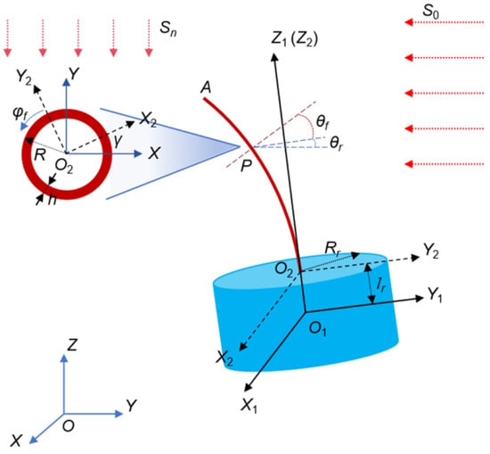
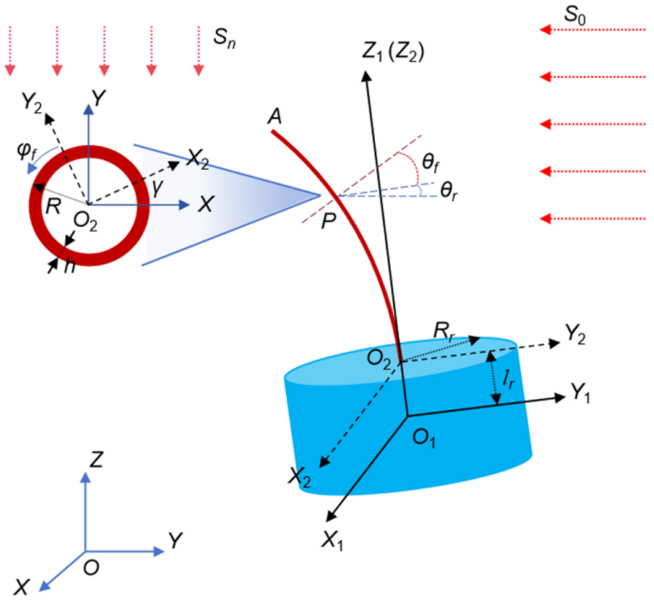
The spacecraft is idealised as a dynamically symmetric rigid body carrying a circular thin-walled flexible beam, as shown in Figure 1. The appendage is clamped to the rigid body at its root and is free at the other end. This configuration is used as a representative reduced-order model for lightweight boom-like spacecraft appendages whose transverse bending response can be excited by solar-thermal loading. An inertial frame OXYZ is used to describe the absolute motion and the fixed solar-radiation direction. A body-fixed principal frame O1X1Y1Z1 is attached to the rigid-body mass centre, with O1Z1 aligned with the symmetry axis of the rigid body. The Cardan angles describe the attitude of O1X1Y1Z1 relative to OXYZ. A beam-root frame O2X2Y2Z2 is attached to the appendage root, with O2Z2 coincident with the undeformed beam centreline. In the ideal reference configuration, O2X2Y2Z2 is related to O1X1Y1Z1 by a fixed mounting transformation and is not an independent attitude frame. It is retained to define the local beam deformation, circumferential temperature perturbation, and thermoelastic bending moments. The solar vector in Figure 1 denotes the inertial solar-radiation direction, whereas the local incidence condition is evaluated in the beam-root frame.
Figure 1.
Mechanical model of a rigid-flexible coupled spinning spacecraft subjected to solar radiation.
The following assumptions are adopted to isolate the spin-modulated thermoelastic bending mechanism. The appendage is modelled as a closed-section thin-walled Euler–Bernoulli beam, and only transverse bending deformation is retained. The wall thickness is much smaller than the cross-section radius; therefore, through-thickness temperature variation is neglected, whereas the first circumferential temperature perturbation is retained because it directly produces thermoelastic bending. The spacecraft operates in a vacuum, so external radiative heating and radiative cooling are considered as the dominant thermal exchange mechanisms. The beam endpoints are taken thermally insulated, and the material properties are assumed to be temperature independent over the considered range. Accordingly, the formulation is intended for pathway identification within the prescribed small-deflection admissibility range, rather than for predicting large-deformation response or a complete orbital thermal environment.
2.2. Mechanical Equations of the Rigid-Flexible Appendage System
The mechanical subsystem describes the coupled motion of the rigid spacecraft body and the transverse bending deformation of the flexible appendage. The attitude of the body-fixed frame (O1X1Y1Z1) relative to the inertial frame (OXYZ) is described by the Cardan angles qθ = [α, β, φ]T, and the angular velocity of the rigid body is expressed in the principal-axis frame as ω1 = [ωx, ωy, ωz]T. The appendage deformation is represented by an assumed-mode approximation,
where qf denotes the retained flexible modal coordinates and Φ is the modal matrix of the appendage. The complete mechanical coordinate vector is written as
where r1 is the position vector of the rigid-body mass centre. They are used to construct the inertia virtual power of the complete rigid-flexible system.
Using Jourdain’s principle [37], the virtual powers of inertia, elastic restoring force, structural damping and thermoelastic bending lead to a compact rigid-flexible mechanical model. In first-order form, the governing equations can be written as
here, qr = r1 contains the rigid-body translational coordinates, and pr and pf are the corresponding first-order mechanical variables. The matrices Mrr, Mrf, Mfr and Mff are the rigid-flexible mass submatrices, while Fr and Ff collect the gyroscopic, convective and other nonlinear inertia terms generated by the coupled rigid-flexible motion. The matrix Kff is the elastic stiffness matrix of the appendage, Cff is the structural damping matrix, and MT is the generalised thermoelastic bending force induced by the circumferential temperature perturbation. The detailed expressions of the mass submatrices and nonlinear inertia terms are provided in Appendix A, so that the main text can focus on the solar-thermal excitation pathway and the response diagnostics.
For the thin-walled Euler–Bernoulli appendage, the bending moments over an arbitrary cross-section can be decomposed into elastic curvature and thermal bending contributions. According to linear thermoelastic theory [38], this relation is expressed as
here, E is the Young’s modulus, αT is the thermal expansion coefficient, ΔT is the temperature variation, Mx and My are the bending moments about O2X2 and O2Y2, respectively, Ix and Iy are the corresponding second moments of area, and κx and κy are the bending curvatures. The corresponding generalised thermoelastic force in modal space is
where Φ1 and Φ2 are the modal matrices associated with the transverse deformations along the O2X2 and O2Y2 directions, and the double prime denotes differentiation with respect to z2. Equation (6) is the mechanical entry point of the solar-thermal excitation: the circumferential temperature perturbation generates MT, which enters the flexible mechanical equations as a generalised force.
Because the spacecraft is assumed to operate in a vacuum, no aerodynamic or environmental mechanical damping is introduced. The damping retained in the appendage model represents equivalent structural dissipation, such as internal material damping and possible joint or root-connection dissipation. It is represented by a Rayleigh damping matrix, written as a linear combination of the mass and stiffness matrices of the flexible beam [39]:
The coefficients α1 and α2 are determined from selected structural frequencies and a prescribed modal damping ratio. The expressions for Mff and Kff are given in Appendix A. Under an equal-damping-ratio assumption, they may be approximately related to the reference frequencies ωi and ωj by
Finally, the Cardan-angle kinematics close the rigid-body attitude part of the mechanical model,
where the transformation matrix associated with the selected (1/2/3) rotation sequence is
2.3. Solar Heating and Circumferential Temperature Perturbation
The thermal subsystem describes how attitude-dependent solar radiation produces the circumferential temperature perturbation responsible for thermoelastic bending. For the thin-walled appendage, temperature variation through the wall thickness is neglected, while the first circumferential temperature variation is retained. Following the coupled thermal-structural idea of Thornton and Kim [10], the absorbed solar heat flux is allowed to depend on the local deformation slope of the appendage. Consequently, the solar-heating source term may vary along the beam length. In the present reduced-order model, this deformation-induced spanwise variation is retained through the local absorbed heat flux and its beam-length projection, whereas independent axial heat-conduction modes are not introduced.
A differential element of the thin-walled beam is considered. From the local thermal equilibrium of this element, the heat-conduction equation can be written as [10]
here, T denotes the local cross-sectional temperature field, λ is the thermal conductivity, h is the wall thickness, R is the cross-section radius, φf is the circumferential coordinate, c is the specific heat, ρ is the material density, σT = 5.67 × 10⁻⁸ W/(m2·K4) is the Stefan-Boltzmann constant, εT is the emissivity, and qs is the absorbed heat flux per unit area on the outer surface of the beam. The dependence of qs on z2 represents the deformation-induced variation of the local solar-incidence condition. Therefore, spanwise dependence enters the thermal excitation through the absorbed heat-flux source, rather than through an independently resolved axial heat-conduction field.
In the full model, the attitude-induced incidence variation and the deformation-induced incidence variation are both retained. This distinction also makes it possible, in the mechanism-identification study, to suppress the deformation-dependent incidence pathway without altering the attitude-dependent solar heating or the thermoelastic bending formulation. The absorbed solar heat flux depends on the attitude of the spacecraft and the deformation of the beam. It is written as
where αs is the absorptivity of the beam surface, S0 is the solar heat-flux intensity, γ is the rotation angle about the beam axis, θr denotes the incidence-angle variation induced by spacecraft attitude motion, and θf(z2, t) denotes the incidence-angle variation induced by beam deformation. The shadowing function δ is equal to 1 when −π/2 ≤ φf + γ ≤ π/2 and is equal to 0 when π/2 ≤ φf + γ ≤ 3π/2.
For analytical and numerical convenience, the retained cross-sectional temperature field is represented by the mean and first circumferential harmonic components, following the approximation used in Ref. [10]:
In this reduced-order implementation, Ta, Tp1 and Tp2 are retained thermal coordinates obtained after beam-length projection. They are not independent axial temperature modes. The z2 dependence caused by deformation-dependent solar incidence is retained in the projected heat-flux terms, which leads to the deformation-related integral terms in Equations (15)–(17).
The quantity Ta is the mean cross-sectional temperature, while Tp1 and Tp2 are the cosine and sine components of the same first circumferential temperature harmonic. Thus, Tp1 and Tp2 are of the same perturbation order, rather than perturbations of different orders. The small perturbation assumption |Tp1|/Ta << 1 and |Tp2|/Ta << 1 is adopted. The two components are retained because the attitude-dependent and deformation-dependent solar incidence can rotate the first-harmonic temperature gradient within the cross-section.
By expanding δcos(φf + γ), substituting Equations (11) and (12) into Equation (10), projecting the heat-balance equation onto the mean, cosine and sine circumferential bases, and retaining the first-harmonic terms, the governing thermal equations for the retained temperature variables are obtained as
where the incidence-angle variations are expressed in terms of the attitude angles and the local appendage slope as
where u’x and u’y are the derivatives of the transverse displacements with respect to z2. Substitution of Equation (14) into the thermal equations, combined with the small-deflection assumption and modal discretisation of the beam deformation, gives the following set of coupled ordinary differential equations for the thermal variables:
where
Thus, the full thermal model retains both attitude-dependent solar heating and deformation-dependent incidence feedback. This distinction is important for the degraded-model comparisons introduced later, because the deformation-dependent incidence pathway can be suppressed without removing the spin-modulated thermoelastic bending pathway. Moreover, based on Equation (12), the generalised thermoelastic bending force (6) can be expressed as
Equations (13)–(18), together with the mechanical equations in Section 2.2 and the attitude kinematic relation, form the closed rigid-flexible-thermal model. In this coupled system, attitude-dependent solar radiation first generates the perturbation temperatures Tp1 and Tp2. These perturbations produce thermoelastic bending moments and the resulting generalised force MT drives the flexible response. The full model retains both the deformation-dependent incidence feedback through θf and the thermoelastic bending pathway through MT. In the degraded-model comparisons introduced later, these two pathways are selectively suppressed while all other equations, parameters and numerical settings are kept unchanged.
2.4. Assumed Modes and Modal Verification
The assumed-mode method represents the flexible deformation by a finite set of admissible functions that satisfy the essential geometric boundary conditions [40]. These functions need not be the exact modes of the complete coupled spacecraft system, but they should efficiently represent the dominant deformation pattern of the appendage. In the present study, the appendage is slender and clamped at the root; therefore, classical Euler–Bernoulli cantilever-beam modes are selected as the admissible functions for the transverse bending deformation. Their suitability for representing the low-frequency bending characteristics of the thin-walled appendage is further checked by the ANSYS (version 19.2).
The transverse deformation of the appendage is approximated by a finite set of Euler–Bernoulli cantilever-beam modes. For each transverse direction, the displacement is written as
The integer n is the number of retained modes and controls the balance between accuracy and computational cost. For the cantilevered thin-walled beam considered here, the assumed modes must satisfy the geometric boundary conditions at the fixed end z = 0:
For the present simulations, the modal expansion is truncated at n = 6 in each transverse direction, using the first six Euler–Bernoulli cantilever-beam mode shapes as the admissible functions. In nondimensional form, the j-th transverse bending mode can be written as [40]
where ξ = z/lf, β1 ≈ 1.875, β2 ≈ 4.694, β3 ≈ 7.855, βj ≈ (j − 1/2)π, for j = 4, 5, ...,
Then, the corresponding natural frequencies are
These admissible functions satisfy the essential geometric boundary conditions at the clamped end and efficiently represent the dominant transverse bending characteristics of the thin-walled beam. The material and geometric constants of the beam are listed in Table 1.
Table 1.
Material and geometric parameters of the thin-walled beam.
The first six assumed-mode frequencies are compared with those obtained from an ANSYS finite-element model in Table 2. The maximum relative difference does not exceed 0.32%, indicating that the selected admissible functions reproduce the low-frequency bending characteristics required for the present reduced-order analysis. The ANSYS reference model represents the isolated appendage using three-node quadratic beam elements (BEAM189) with the circular-tube cross-section defined in Table 1. The root vertex is fully fixed, the opposite end is free, and a linear, undamped and prestress-free modal analysis is performed.
Table 2.
Natural frequencies of the thin-walled beam obtained by the assumed-mode method and ANSYS.
A three-level mesh-refinement study using 20, 40 and 80 elements, corresponding to element sizes of 0.375, 0.1875 and 0.09375 m, respectively, gives a maximum medium-to-fine frequency difference of 0.0077% for the first six bending modes. The original 20-element model used in Table 2 differs from the 80-element fine-mesh results by at most 0.092%. The comparison therefore provides an independent modal consistency check for the assumed-mode representation. The first bending frequency, f1 = 0.30759 Hz, is used later as a reference in the frequency-proximity analysis.
2.5. Numerical Implementation and Parameter Settings
The coupled system consists of the mechanical equations in Equations (3) and (4) and the thermal equations in Equations (15)–(17). The state variables include the rigid-body translational and attitude variables, the angular velocity components, the retained flexible modal coordinates and velocities, and the thermal variables. In the following numerical study, ω denotes the angular velocity vector, whereas Ω denotes the prescribed spin rate reported in revolutions per minute. The corresponding spin frequency is denoted by fΩ = Ω/60 in Hz. The initial solar incidence condition is specified through the initial attitude angle α0.
The structural material and geometric parameters of the appendage are listed in Table 1. The remaining fixed rigid-body, thermal, radiative and geometric parameters used in the numerical simulations are summarised in Table 3.
Table 3.
Material, thermal and geometric parameters of the rigid-flexible spacecraft.
The nonlinear ordinary differential equations were implemented in MATLAB (R2018a)and integrated using the variable-step stiff solver ode15s. Unless otherwise stated, the relative tolerance, absolute tolerance and maximum time step were set to 10−5, 10−7 and 0.05 s, respectively. All coupled simulations reported in this study retained the first six bending modes in each transverse direction, giving twelve flexible modal coordinates in total. For each pair of α0 and Ω, an initial transient interval was discarded and the subsequent response was sampled once per spin period for response classification.
The numerical campaign was organised hierarchically. Coarse two-parameter maps in the α0-Ω plane were first used to identify the main response regions. Dense one-parameter spin-rate sweeps were then performed within the sampled high-spin classification transition region, because narrow admissible and loss-of-admissibility intervals may be missed by a coarse grid. Representative cases were recomputed with retained time histories to examine the time response, spin-period samples, phase portraits and return maps.
2.6. Spin-Period Response Sampling and Admissibility Classification
For each successfully integrated parameter point, the post-transient response is sampled once per spin period. The sampling instants are
where t0 is the beginning of the retained interval and Np is the number of retained spin-period samples. For a retained scalar response sequence zk = z(tk), the response spread is defined as
In the present study, the main spread indicators are the beam-tip displacement spread Δytip, the first flexible modal-coordinate spread Δqf11, and the attitude-angle spread Δβ. These quantities are used to visualise how the post-transient response changes with spin rate and initial solar-incidence angle. These quantities play different roles in the assessment: Δytip is used as the primary geometric admissibility indicator for the small-deflection appendage model, whereas Δqf11 and Δβ are retained as supplementary modal and attitude-response diagnostics.
Because the formulation is a small-deflection reduced-order model, the admissibility criterion is tied specifically to the geometric deformation of the appendage rather than to a general multi-criteria stability or structural-failure boundary. The reconstructed beam-tip displacement is a physical, mode-normalisation-independent quantity that contains contributions from all retained flexible modes and must satisfy
For the appendage length used in this study, lf = 7.5 m, this gives yadm = 0.75 m. This threshold is not a structural failure criterion. It is used only to identify the response range within which the small-deflection reduced-order model can be interpreted as admissible. No independent threshold is imposed on qf11 or β because modal-coordinate amplitudes depend on the normalisation of the assumed functions, while hub attitude oscillation does not by itself indicate violation of the appendage small-deflection assumption. Instead, Δqf11 and Δβ are examined together with Δytip as supplementary diagnostics of the modal and rigid-body response.
A parameter point is classified as an admissible bounded response if the integration is completed and the beam-tip displacement remains within the admissibility bound after the transient interval. A parameter point is classified as a loss-of-admissibility case if the beam-tip displacement exceeds yadm. If numerical integration terminates after the response has already exceeded the admissibility bound, the case is still interpreted as a loss of admissibility rather than as a large-amplitude bounded response. This classification avoids attributing physical significance to large-deflection behaviour outside the validity range of the reduced-order model.
2.7. Degraded Models for Mechanism Identification
To identify the thermal-coupling pathway responsible for the representative high-spin loss-of-admissibility responses, the full model is compared with three degraded models. In the first degraded model, the deformation-dependent incidence feedback is suppressed by setting
in the thermal equations. The attitude-dependent solar heating and the thermoelastic bending force are otherwise retained. This model tests whether deformation-induced modification of the solar incidence condition is necessary for the observed high-spin response amplification.
In the second degraded model, the thermoelastic bending pathway is suppressed by setting
in the flexible mechanical equations. The thermal equations are otherwise unchanged. This model tests whether the direct thermoelastic bending moment is necessary for the observed high-spin loss-of-admissibility responses.
In the third, dual-degradation model, the two conditions in Equations (26) and (27) are imposed simultaneously, i.e., θf = 0 and MT = 0. This model tests whether any residual thermal-to-mechanical forcing pathway remains after both deformation-dependent incidence feedback and thermoelastic bending are removed.
All other parameters, initial conditions, solver settings and response-classification criteria are kept identical to those of the full model. Therefore, differences among the four model variants can be attributed to the individually or simultaneously suppressed coupling pathways.
2.8. Modal Energy and Thermoelastic-Work Diagnostics
Modal diagnostics are used to relate the representative high-spin loss-of-admissibility cases to the dominant structural mode. The structural energy associated with the j-th retained bending mode is evaluated from the modal displacement and velocity components as
where qf,j and pf,j denote the modal displacement and velocity components associated with the j-th bending mode, and Mj and Kj are the corresponding modal mass and stiffness submatrices. The post-transient modal energy fraction is then defined as
where <·> denotes averaging over the retained response interval. This fraction is used to determine whether the flexible structural energy becomes concentrated in a dominant bending mode near the high-spin transition.
To identify the modal pathway through which the solar-thermal excitation enters the flexible subsystem, the instantaneous thermoelastic power associated with the j-th bending mode is defined as
The accumulated positive thermoelastic work is used to identify which mode receives the dominant thermal work input. Together with the detuning between fΩ and the appendage bending frequencies, these diagnostics provide a physical interpretation of the spin-rate-dependent changes in response classification.
2.9. Robustness Checks
Additional checks are performed to assess the robustness of the response classification. Representative bounded and loss-of-admissibility cases are recomputed using different solver tolerances, maximum time steps, thermal-evaluation settings and admissibility bounds. A supplementary sampling-resolution check is also performed over 19.6–19.7 rpm using spin-rate increments of 0.02, 0.01 and 0.005 rpm for α0 = −80° and +80°. These checks assess numerical and classification sensitivity without altering the assumptions of the reduced-order model.
3. Results
This section first presents the global dependence of the flexible response on the initial solar-incidence angle and spin rate. Local spin-rate sampling is then used to characterise the admissibility classifications in the high-spin region. Representative time histories and response geometries, degraded-model comparisons, modal energy/work diagnostics and robustness checks are subsequently reported.
3.1. Global Response Characteristics in the Incidence Angle/Spin-Rate Plane
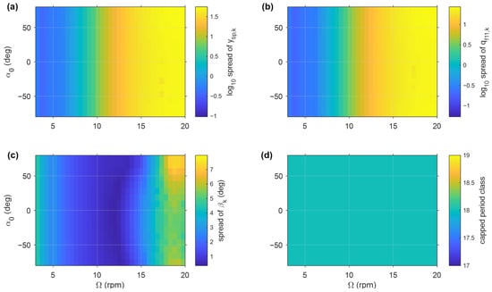
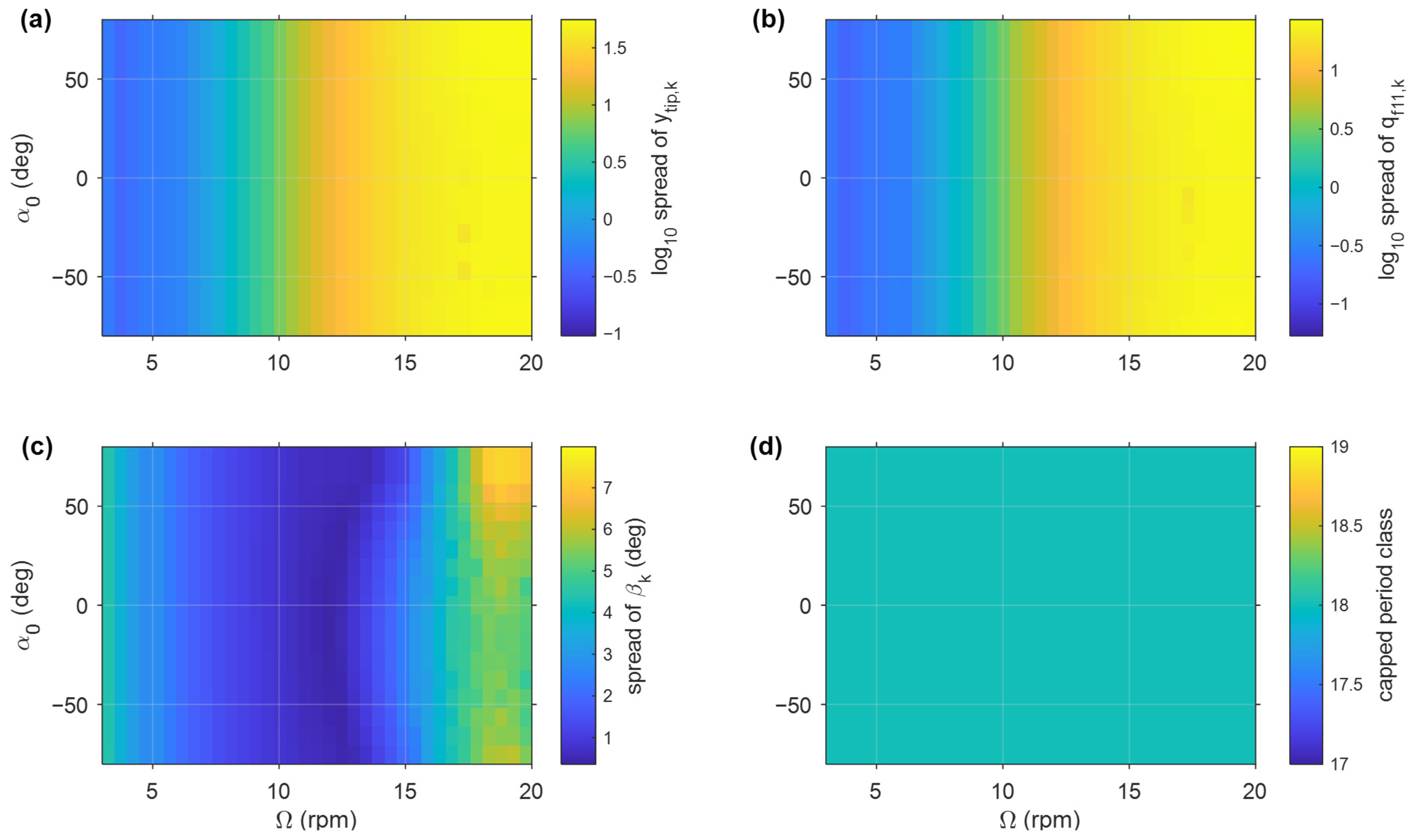
A coarse two-parameter analysis was first performed over the initial solar-incidence angle α0 and the spin rate Ω. The response maps in Figure 2 were obtained from post-transient spin-period samples of the full coupled model, including only admissible bounded responses.
Figure 2.
Global response maps of the full coupled model in the initial-incidence-angle/spin-rate plane: (a) logarithmic spread of the retained beam-tip displacement samples; (b) logarithmic spread of the retained first flexible modal-coordinate samples; (c) spread of the attitude angle β; (d) capped period-class indicator based on the retained spin-period samples.
Figure 2a,b show the logarithmic spreads of the beam-tip displacement Δytip and the first flexible modal coordinate Δqf11. Both indicators remain small at low spin rates and increase by orders of magnitude toward the high-spin region, whereas their variation with α0 is weaker over most of the parameter plane. The response is therefore globally more sensitive to Ω than to α0, although α0 modifies the detailed admissibility classification in the high-spin region.
Figure 2c shows that the attitude-angle spread Δβ remains relatively small over an intermediate spin-rate range and increases toward both lower and higher spin rates. Figure 2d provides a capped period-class indicator for describing the sampled response pattern. Based on these global trends, local spin-rate sampling is performed for α0 = −80° and +80°.
3.2. Local Spin-Rate Response in the High-Spin Region
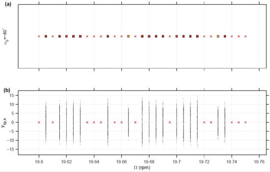
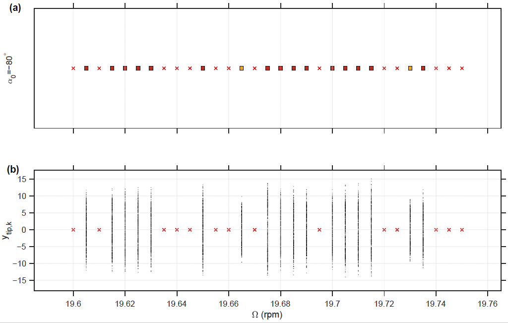
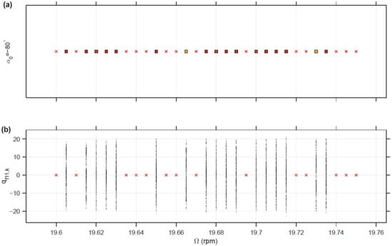
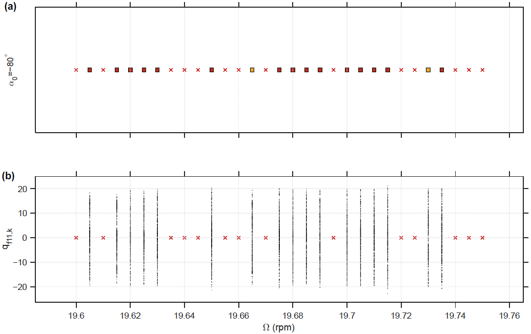
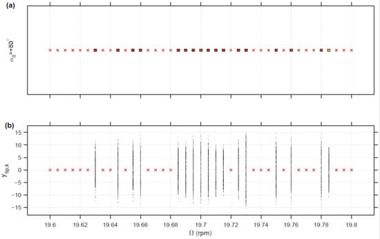
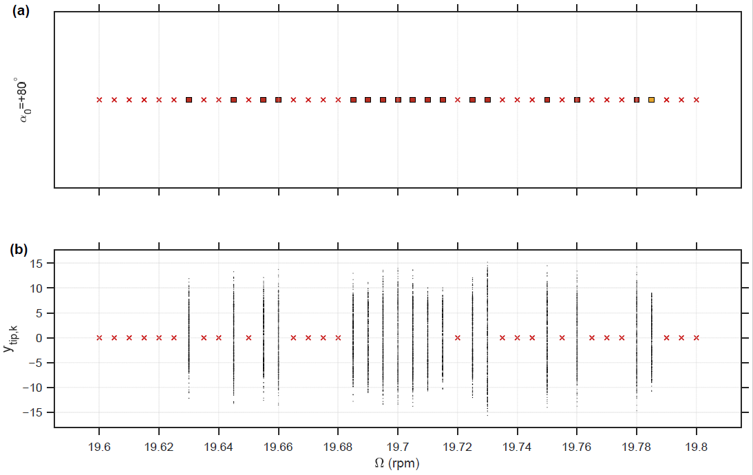
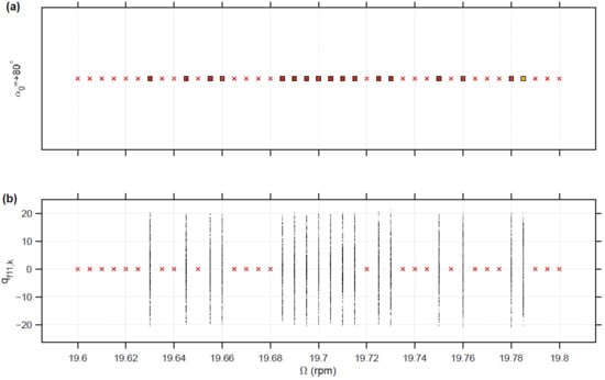
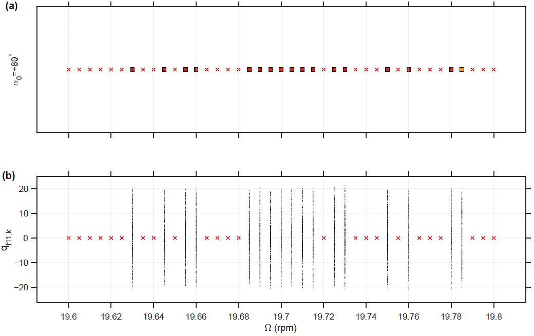
Local spin-rate sampling was performed for α0 = −80° and α0 = +80° in the high-spin region identified from the global maps. Figure 3, Figure 4, Figure 5 and Figure 6 show the retained spin-period samples of the beam-tip displacement ytip,k and the first flexible modal coordinate qf11,k. Only admissible bounded responses are plotted as sampled ordinates, while red crosses denote spin-rate points at which |ytip| exceeds yadm.
Figure 3.
Local spin-rate response diagram of the full coupled model for α0 = −80°: (a) admissibility classification of each spin-rate point; (b) retained spin-period samples of the beam-tip displacement. Yellow and dark-red squares denote large and very large bounded responses, respectively; red crosses denote loss of admissibility, and black dots represent retained spin-period samples.
Figure 4.
Local spin-rate response diagram in the sampled high-spin region for α0 = −80°: (a) admissibility classification of each spin-rate point; (b) retained spin-period samples of the first flexible modal coordinate. Yellow and dark-red squares denote large and very large bounded responses, respectively; red crosses denote loss of admissibility, and black dots represent retained spin-period samples.
Figure 5.
Local spin-rate response diagram in the sampled high-spin region for α0 = +80°: (a) admissibility classification of each spin-rate point; (b) retained spin-period samples of the beam-tip displacement. Yellow and dark-red squares denote large and very large bounded responses, respectively; red crosses denote loss of admissibility, and black dots represent retained spin-period samples.
Figure 6.
Local spin-rate response diagram in the sampled high-spin region for α0 = +80°: (a) admissibility classification of each spin-rate point; (b) retained spin-period samples of the first flexible modal coordinate. Yellow and dark-red squares denote large and very large bounded responses, respectively; red crosses denote loss of admissibility, and black dots represent retained spin-period samples.
For both incidence conditions, neighbouring spin-rate points may have different admissibility classifications, although the detailed locations of the admissible intervals differ. Here, neighbouring sampled points with different classifications are described as a sampled classification transition. No unique or converged critical spin rate is inferred from these sampled transitions.
The first bending frequency of the appendage is f1 = 0.30759 Hz, corresponding to approximately 18.46 rpm. The cases at Ω = 19.6 and 19.7 rpm give fΩ/f1 ≈ 1.06–1.07 and fΩ/f2 ≈ 0.17. They are selected as representative high-spin loss-of-admissibility cases for detailed diagnostics, rather than as adjacent points bracketing a unique critical rotational speed.
Figure 6 shows that qf11,k follows the same local classification pattern as the beam-tip displacement, confirming that the changes are reflected directly in the retained flexible response. Figure 3, Figure 4, Figure 5 and Figure 6 therefore resolve local classification changes that are not visible in the coarse global maps and provide the basis for the subsequent modal diagnostics.
3.3. Representative Admissibility Checks of the Full Coupled Model
Representative cases were examined to verify the admissibility classification in the sampled high-spin region. The diagnostics include time histories, spin-period samples, phase portraits, return maps and the displacement bound defined in Section 2.6.
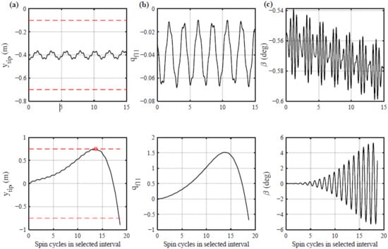
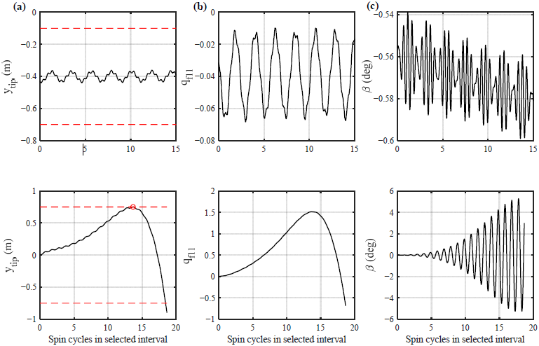
Figure 7 compares an admissible reference case, α0 = 0° and Ω = 15.0 rpm, with a high-spin case, α0 = +80° and Ω = 19.6 rpm. The reference case remains well within the admissible bound yadm = 0.1 lf = 0.75 m, and its ytip, qf11 and β responses remain bounded after the transient interval. In contrast, the high-spin case shows rapid growth of the flexible response and eventually exceeds yadm. It is therefore classified as a loss-of-admissibility case.
Figure 7.
Representative time histories of the full coupled model. The upper and lower rows correspond to the bounded reference case α0 = 0°, Ω = 15.0 rpm and the high-spin loss-of-admissibility case α0 = +80°, Ω = 19.6 rpm, respectively: (a) ytip; (b) qf11; (c) β. Red dashed lines denote yadm = 0.1 lf, not a structural failure criterion.
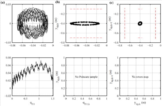
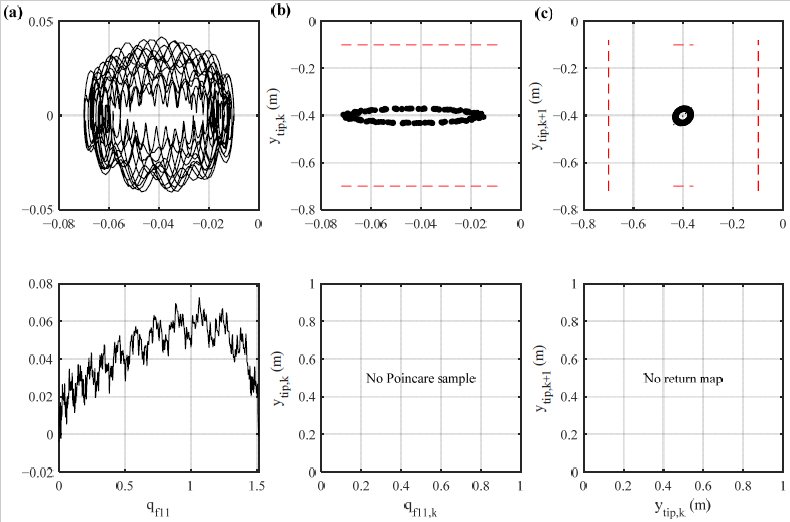
Figure 8 further illustrates the local response geometry using the first flexible modal coordinate and the spin-period sampled beam-tip displacement. For the bounded reference case, the (qf11, ) phase portrait remains compact, the retained spin-period samples form a bounded set, and the return map (ytip,k, ytip,k+1) remains confined. These features are consistent with an admissible post-transient response. For the high-spin case, the response leaves the compact bounded region and subsequently reaches the admissibility bound. Therefore, the spin-period samples shown for this case are used only to illustrate how the response evolves before the loss of admissibility. They are not used to characterise a converged long-time bounded response, because the present small-deflection reduced-order model is no longer interpreted as admissible once |ytip| exceeds yadm.
Figure 8.
Representative local response geometry of the full coupled model. The upper row shows the bounded reference case α0 = 0°, Ω = 15.0 rpm, and the lower row shows the high-spin loss-of-admissibility case α0 = +80°, Ω = 19.6 rpm: (a) modal phase portrait (qf11, ); (b) retained spin-period samples of ytip,k; (c) return map (ytip,k, ytip,k+1). Red dashed lines denote the admissibility bound yadm = 0.1lf.
Together, Figure 7 and Figure 8 complement the admissibility classification: the time histories identify when the admissibility bound is reached, while the phase portrait, spin-period samples and return map illustrate the pre-loss response evolution. Therefore, the high-spin case is interpreted as a loss-of-admissibility process rather than a converged bounded response.
Table 4 summarises the representative classifications. The reference case has max|ytip| = 0.103 m and Δytip = 0.205 m, whereas the high-spin cases at Ω = 19.6–19.7 rpm exceed the admissibility bound for both α0 = −80° and α0 = +80°. Their frequency ratios are fΩ/f1 = 1.062 − 1.067 and fΩ/f2 ≈ 0.17.
Table 4.
Representative admissibility check for the full coupled model under selected low- and high-spin conditions.
3.4. Degraded-Model Comparison
The full coupled model was compared with the three degraded models defined in Section 2.7. In the first degraded model, the deformation-dependent incidence feedback was removed by setting θf = 0. In the second degraded model, the thermoelastic bending force was removed by setting MT = 0. In the dual-degradation model, both conditions were imposed simultaneously. All other parameters, initial conditions, solver settings and admissibility criteria were kept unchanged.
Table 5 summarises the classifications of the representative cases. The cases with α0 = −80° and +80° were calculated separately but are combined in the table because they produced identical response classifications. The reference case at α0 = 0° and Ω = 15.0 rpm remains bounded in all four model variants. For the high-spin cases at Ω = 19.6–19.7 rpm, both the full model and the θf = 0 model exceed the admissibility bound. In contrast, the MT = 0 and dual-degradation models remain bounded with zero flexible response under the prescribed initial conditions.
Table 5.
Degraded-model comparison for mechanism identification.
These results show that suppressing the deformation-dependent incidence feedback alone does not change the response classifications, whereas removing the thermoelastic bending force eliminates the thermally driven flexible response under the prescribed initial conditions. The dual-degradation model reproduces the MT = 0 beam-tip response for all representative cases, with δtip = 0 within numerical precision, confirming that no additional thermal-to-mechanical forcing pathway remains after MT is removed.
3.5. Detuning, Model Energy and Thermoelastic Work Diagnostics
Table 6 summarises the frequency-proximity, modal-energy and thermoelastic-work diagnostics of the full coupled model. For the bounded reference case at Ω = 15.0 rpm, the spin-frequency ratio is fΩ/f1 = 0.81268. For the high-spin loss-of-admissibility cases at Ω = 19.6 and 19.7 rpm, fΩ/f1 increases to 1.06190 and 1.06730, respectively. These values show that the high-spin cases are located close to the first bending-frequency region, but they are not treated as exact resonance conditions.
Table 6.
Representative frequency-proximity, first-mode energy fraction and first-mode positive thermoelastic-work fraction of the full coupled model.
The modal-energy results show strong first-mode dominance in the high-spin cases. The first-mode energy fractions are 0.99956 and 0.99920 for Ω = 19.6 and 19.7 rpm, respectively. The corresponding first-mode fractions of accumulated positive thermoelastic work are 0.69146 and 0.71007. The bounded reference case also has a large first-mode energy fraction of 0.86513, but its response remains within the admissible displacement range. The overwhelming first-mode energy concentration also supports the use of the beam-tip displacement as the primary geometric admissibility indicator, because the dominant cantilever-bending mode reaches its maximum transverse displacement at the free end.
Thus, first-mode dominance alone does not determine the loss-of-admissibility classification. The high-spin cases combine proximity to the first bending-frequency region, dominant first-mode energy retention and positive thermoelastic work input to the first bending mode. The concentration of response energy and positive thermal work in the first bending mode is consistent with earlier thermal-structural studies in which thermally induced dynamic response was governed mainly by low-order bending modes and by the relation between thermal and structural time scales [10,14,15].
3.6. Robustness of the Admissibility Classification
Robustness checks were performed for representative bounded and high-spin loss-of-admissibility cases. The solver tolerances, maximum time step, thermal-evaluation settings and admissibility bound were varied while the same response-classification rules were applied.
Table 7 compares the baseline and refined integration results. The bounded reference case at α0 = 0° and Ω = 15.0 rpm remains admissible, with max|ytip| = 0.102792 m in both settings. The high-spin cases at α0 = +80° and Ω = 19.6–19.7 rpm reach the admissibility bound under both the baseline and refined settings and therefore retain the loss-of-admissibility classification. The post-threshold amplitudes listed in Table 7 are reported only as numerical integration outputs for comparing the two solver settings and are not physically interpreted.
Table 7.
Robustness check of the admissibility classification.
The classifications are unchanged when the admissibility bound is varied from 0.05lf to 0.15lf and when the thermal quadrature and illumination-transition settings are modified. Refining the spin-rate increment from 0.02 to 0.01 and 0.005 rpm also leaves all sampled points over 19.6–19.7 rpm classified as loss of admissibility for both α0 = −80° and +80°. Thus, the loss-of-admissibility classification within the selected 19.6–19.7 rpm interval is insensitive to the tested numerical settings and to the sampling increment down to 0.005 rpm. This result demonstrates classification consistency within the selected interval, rather than convergence of a uniquely defined critical spin-rate boundary.
4. Discussion
The results show that spin rate is the primary parameter controlling the flexible response, while the initial solar-incidence angle mainly modifies the local classification in the sampled high-spin region. Frequency proximity, modal energy and thermoelastic-work diagnostics consistently associate the representative high-spin loss-of-admissibility cases with the first bending mode. This behaviour is not interpreted as a simple linear resonance, because the response also depends on attitude motion, thermal dynamics, shadowing, damping and rigid-flexible coupling.
The degraded-model comparisons identify the thermal-to-mechanical pathway. Setting θf = 0 does not remove the representative high-spin loss-of-admissibility cases, whereas setting MT = 0 eliminates the thermally driven flexible response under the prescribed initial conditions. The dual-degradation model reproduces the MT = 0 response within numerical precision, confirming that no residual thermal-to-mechanical forcing pathway remains after the generalised thermoelastic force is removed. Together with the θf = 0 comparison, these results show that thermoelastic bending is the necessary forcing pathway for the representative high-spin responses within the present formulation and tested cases.
The present interpretation is consistent with earlier studies showing that spin motion and appendage flexibility modify attitude–vibration coupling [1,2,35,36], and that non-uniform heating, incidence geometry, thermal/structural time scales and damping influence thermoelastic vibration [10,14,15,20]. The present work extends these findings by showing how spin-modulated circumferential heating transfers positive thermal work into the dominant bending mode through the generalised thermoelastic force.
From an engineering perspective, spin-rate selection should be considered together with modal-frequency placement and worst-case solar-incidence attitudes. Operation near low-order bending-frequency regions should be avoided where practical. Potential mitigation measures include spin-rate scheduling, attitude constraints, structural frequency tuning, including prestress-based tuning [41], and increased structural damping.
Several limitations remain. The model is restricted to small-deflection Euler–Bernoulli bending and does not include large-deformation geometric nonlinearity, cross-sectional distortion or temperature-dependent properties. Related nonlinear aeroelastic and thermal-vibration studies show that geometric nonlinearity can modify vibration and stability characteristics [42,43]; therefore, the present frequency-based interpretation is limited to responses within the prescribed admissibility range. The thermal model also retains only the first circumferential harmonic and simplified radiation exchange, whereas a complete orbital environment may include eclipse, albedo, infrared radiation, detailed self-shadowing and spatially varying surface properties.
Future work should combine ground-based thermal-structural testing with response-based model updating. Nonlinear subspace-identification and dynamic-load-identification methods may support the calibration of structural parameters and the reconstruction of equivalent time-varying or periodic thermal loads [44,45,46]. Further extensions should consider geometrically nonlinear structural models, higher-fidelity orbital thermal environments and control or operational strategies for mitigating spin-modulated thermoelastic response.
5. Conclusions
This study developed a reduced-order rigid-flexible-thermal framework to identify the dominant pathway of spin-modulated thermoelastic response in a flexible spacecraft appendage. The main conclusions are as follows:
- (1)
- The post-transient flexible response is governed primarily by spin rate. The structural-response spreads increase markedly in the high-spin region, whereas the initial solar-incidence angle has a weaker global influence but modifies the local classification.
- (2)
- The representative high-spin loss-of-admissibility cases lie near the first bending-frequency region and exhibit dominant first-mode energy retention and positive thermoelastic work input to the first bending mode. The sampled classification transitions describe changes between admissible and loss-of-admissibility responses at the investigated parameter points; they are not interpreted as a uniquely determined critical spin rate.
- (3)
- Removing deformation-dependent incidence feedback does not eliminate the representative high-spin cases, whereas removing the thermoelastic bending force suppresses the thermally driven flexible response. The dual-degradation result further confirms thermoelastic bending as the essential thermal-to-mechanical pathway within the present formulation.
- (4)
- The response classifications remain unchanged under the tested solver, thermal-evaluation, admissibility-bound and spin-rate-sampling variations. These findings indicate that spin rate, modal-frequency proximity and thermoelastic work input should be considered jointly in structural verification and operational planning.
Author Contributions
Conceptualization, X.Z. and H.B.; methodology, X.Z. and Y.L.; software, O.L.; formal analysis, X.Z.; investigation, O.L., X.Z., Y.L., P.L. and H.B.; data curation, X.Z., Y.L. and P.L.; writing—original draft preparation, O.L. and X.Z.; writing—review and editing, O.L. and X.Z.; visualization, O.L.; supervision, P.L. and H.B. All authors have read and agreed to the published version of the manuscript.
Funding
This research was funded by the National Natural Science Foundation of China [grant number 12402051], the Natural Science Foundation of Inner Mongolia Autonomous Region of China [grant numbers 2024QN01002, 2024ZD22].
Data Availability Statement
The original contributions presented in this study are included in the article. Further inquiries can be directed to the corresponding authors.
Acknowledgments
The authors acknowledge the support of the Inner Mongolia Academician Workstation for New Energy Intelligent Equipment and Operation Maintenance in IMUT.
Conflicts of Interest
The authors declare no conflicts of interest.
Appendix A
The explicit expressions of the mass submatrices and nonlinear inertia terms used in Equation (4) are given below. Here, qf1 and qf2 denote the retained modal-coordinate vectors associated with the transverse deformation components along the O2 × 2 and O2Y2 directions, respectively. The matrices Φ1 and Φ2 are the corresponding assumed-mode matrices.
here, cα = cosα, sα = sinα, etc., are used as compact trigonometric notations.
here Ar and Cr are the equatorial and polar moments of inertia of the main rigid body, respectively, and
here
References
- Shen, Z.X.; Hu, G.K. Thermally induced dynamics of a spinning spacecraft with an axial flexible boom. J. Spacecr. Rocket. 2015, 52, 1503–1507. [Google Scholar] [CrossRef] [Scilit]
- Liu, Y.; Li, X.; Qian, Y.J.; Yang, H.L. Rigid-flexible coupled dynamic and control for thermally induced vibration and attitude motion of a spacecraft with hoop-truss antenna. Appl. Sci. 2022, 12, 1071. [Google Scholar] [CrossRef] [Scilit]
- Gong, D.H.; Wei, X.Q.; Liu, H.L.; Li, F.M. Vibration characteristics of asymmetric flexible cantilever beams connected to a central rigid body. Machines 2024, 12, 193. [Google Scholar] [CrossRef] [Scilit]
- Fang, B.; Cao, D.Q.; Chen, C.; Tian, Y.S.; Li, Y.X. Influence of structural flexibility on nonlinear vibrations induced by orbital maneuver for a tethered spacecraft. J. Aerosp. Eng. 2023, 36, 04022121. [Google Scholar] [CrossRef] [Scilit]
- Zhang, S.Q.; Lai, W.J.; Huang, C.Y.; Cai, C.S.; Lin, C.H. Dynamic modeling and control of rigid-flexible-thermo-electrically coupled piezoelectric integrated smart spacecraft. Appl. Math. Model. 2025, 140, 115896. [Google Scholar] [CrossRef] [Scilit]
- Wang, H.; Yan, H.; Tian, L.; Zang, X.; Zu, Y.Q. Integrated dynamic modeling and ground test validation for spacecraft micro-vibration suppression considering disturbance, isolation, and pointing control. Sensors 2026, 26, 3534. [Google Scholar] [CrossRef] [Scilit] [PubMed]
- Rogers, G.D.; Kinnison, J.D.; Brandt, P.C.; Cocoros, A.A.; Paul, M.V. Dynamic challenges of long flexible booms on a spinning outer heliospheric spacecraft. In Proceedings of the 2021 IEEE Aerospace Conference, Big Sky, MT, USA, 6–13 March 2021; IEEE: New York, NY, USA, 2021; pp. 1–11. [Google Scholar] [CrossRef] [Scilit]
- Ghaleh, P.B.; Malaek, S.M. On dynamic stiffness of spacecraft flexible appendages in deployment phase. Aerosp. Sci. Technol. 2015, 47, 1–9. [Google Scholar] [CrossRef] [Scilit]
- Zhang, L.; Ren, H.; Yuan, T.F.; Fan, W. Dynamic modeling and attitude maneuver control on SO(3) for spacecraft with large flexible appendages. Acta Astronaut. 2025, 228, 551–560. [Google Scholar] [CrossRef] [Scilit]
- Thornton, E.A.; Kim, Y.A. Thermally induced bending vibrations of a flexible rolled-up solar array. J. Spacecr. Rocket. 1993, 30, 438–448. [Google Scholar] [CrossRef] [Scilit] [PubMed]
- Parisse, M.; Angeletti, F. Thermo-mechanical jitter in slender space structures: A simplified modeling approach. Aerospace 2024, 11, 694. [Google Scholar] [CrossRef] [Scilit]
- Xing, X.F.; Shen, Z.X. Thermoelastic–structural dynamics analysis of a satellite with composite thin-walled boom. Acta Mech. 2023, 234, 1259–1273. [Google Scholar] [CrossRef] [Scilit]
- Gu, X.D.; Zhao, B.X.; Jing, Y.; Deng, Z.C.; Zhang, K. Dynamic modeling and thermally induced vibration of the sun-facing beam under gravity gradient. Acta Astronaut. 2026, 239, 796–806. [Google Scholar] [CrossRef] [Scilit]
- Babilio, E. Vibration of Thin-Walled Tubes in Thermal Environment. In Proceedings of ASME 2024 International Design Engineering Technical Conferences and Computers and Information in Engineering Conference, IDETC-CIE2024; ASME: New York, NY, USA, 2024; Volume 9. [Google Scholar] [CrossRef] [Scilit]
- Motaharifard, O.; Daneshjou, K.; Bakhtiari, M. Nonlinear stability and vibration of flexible spacecraft solar arrays under thermally induced flutter during the penumbra phase. Sci. Rep. 2026, 16, 9856. [Google Scholar] [CrossRef] [Scilit] [PubMed]
- Sedelnikov, A.; Serdakova, V.; Orlov, D.; Nikolaeva, A. Investigating the temperature shock of a plate in the framework of a static two-dimensional formulation of the thermoelasticity problem. Aerospace 2023, 10, 445. [Google Scholar] [CrossRef] [Scilit]
- Zhou, Z.X.; Xu, Y. Thermo-flexible coupled dynamics of composite laminated plates based on absolute nodal coordinate formulation. Mech. Adv. Mater. Struct. 2025, 32, 4673–4689. [Google Scholar] [CrossRef] [Scilit]
- Shen, Z.X.; Li, H.J.; Liu, X.N.; Hu, G.K. Thermal shock induced dynamics of a spacecraft with a flexible deploying boom. Acta Astronaut. 2017, 141, 123–131. [Google Scholar] [CrossRef] [Scilit]
- Bormotov, A.; Orlov, D. Investigation of perturbations arising from temperature shock with a symmetrical arrangement of flexible elements of a small spacecraft. Symmetry 2023, 15, 1331. [Google Scholar] [CrossRef] [Scilit]
- Liu, L.; Sun, S.P.; Cao, D.Q.; Liu, X.Y. Thermal-structural analysis for flexible spacecraft with single or double solar panels: A comparison study. Acta Astronaut. 2019, 154, 33–43. [Google Scholar] [CrossRef] [Scilit]
- Zhou, X.L.; Masia, R.; Bai, H.W.; Pagani, A.; Chen, W.Q. Static/quasi-static thermomechanical analysis of 3D thin-walled beam structures based on CUF considering radiation dissipation condition. Mech. Adv. Mater. Struct. 2026, 33, 2453102. [Google Scholar] [CrossRef] [Scilit]
- Jin, C.C.; Liu, X.; Cai, G.P.; Liu, F.C.; Sun, J.; Zhu, D.F. Rigid-flexible-thermal coupling dynamics modeling and attitude-vibration-deformation integrated control strategy of ultra-large space phased array antenna. Aerosp. Sci. Technol. 2026, 168, 110893. [Google Scholar] [CrossRef] [Scilit]
- Yuan, T.T.; Lei, B.; Liu, J.Y.; Wu, Y.L. Rigid-flexible-thermal coupling dynamics of a hub and multiplate system considering frictional contact. Multibody Syst. Dyn. 2023, 59, 363–394. [Google Scholar] [CrossRef] [Scilit]
- Zhang, W.; Zhang, S.J.; Dong, Z.Z.; Wang, H.B.; Yang, D.L.; Chen, M.; Liu, X.Z. Rigid-Flexible-Thermal Coupling Dynamics for Spacecraft with a Composite-Laminated Solar Array in a Space Thermal Environment. J. Aerosp. Eng. 2026, 39, 04025123. [Google Scholar] [CrossRef] [Scilit]
- Zhou, Z.X.; Xu, Y.; Xu, Y.; Cao, C.; Sheng, X.W. Dynamics for rigid-flexible-thermal coupled solar panel multibody system composed of composite laminated shells. Mech. Based Des. Struct. Mach. 2025, 53, 7382–7407. [Google Scholar] [CrossRef] [Scilit]
- Jiang, G.W.; Ma, E.R.; Xu, X.F.; Zhang, R. Thermally induced satellite vibrations: Rigid-flexible-thermal coupling in LEO, GEO, and DRO. Int. J. Aeronaut. Space Sci. 2026, 27, 1477–1493. [Google Scholar] [CrossRef] [Scilit]
- Tian, Q.L.; Yu, Z.Q.; Lan, P.; Lu, N.L. Thermal-dynamic coupled analysis and model order reduction of multibody system. Chin. J. Theor. Appl. Mech. 2022, 54, 2588–2600. [Google Scholar] [CrossRef]
- Tian, Q.L.; Pan, C.Y.; Liu, Z.; Chen, X.M. Model Order Reduction for Rigid-Flexible-Thermal Coupled Viscoelastic Multibody System via the Modal Truncation with Complex Global Modes. Actuators 2025, 14, 479. [Google Scholar] [CrossRef] [Scilit]
- Yu, Z.Q.; Shen, Y.B. Dynamics Analysis of Multibody Systems Based on Flexible Thermal Coupling Solid Elements. Actuators 2025, 14, 606. [Google Scholar] [CrossRef] [Scilit]
- Zhang, F.L.; Zhang, F.Z.; Liang, N. The study of thermal-structural coupling deformation analysis for flexible space manipulator in orbit. J. Therm. Sci. Eng. Appl. 2024, 16, 091004. [Google Scholar] [CrossRef] [Scilit]
- Xue, M.D.; Xiang, Z.H. Review of thermal-dynamical analysis methods for large space structures. Chin. J. Theor. Appl. Mech. 2022, 54, 2361–2376. [Google Scholar] [CrossRef]
- Wang, Y.B.; Qian, Y.J.; Wang, Y.W.; Yang, X.D.; Xu, L. Flutter analysis of a rigid-flexible coupled composite space structure with momentum wheels under thermal load. Aerosp. Sci. Technol. 2024, 148, 109114. [Google Scholar] [CrossRef] [Scilit]
- Shen, Z.X.; Hao, S.W.; Li, H.J. Thermoviscoelasitc dynamics of composite thin-walled booms on spacecrafts subjected to solar radiation. Compos. Struct. 2022, 294, 115795. [Google Scholar] [CrossRef] [Scilit]
- Zhou, S.J.; Yang, Z.; Zhang, K.C.; Liu, X.; Cai, G.P. Rigid-flexible-thermal coupling dynamic modelling and attitude control of large spaceborne deployable parabolic truss antenna. Adv. Space Res. 2026, 77, 5364–5381. [Google Scholar] [CrossRef] [Scilit]
- Han, Z.Q.; Hu, W.P.; Yan, X.Y.; Linghu, T.J.; Deng, Z.C. Effects of time-varying mass distribution on orbit-attitude-vibration coupling characteristics of dumbbell-shaped spatial structure. Aerosp. Sci. Technol. 2026, 177, 112230. [Google Scholar] [CrossRef] [Scilit]
- Jia, Z.B.; Fan, W.; Zhou, P.; Ren, H. Efficient explicit simulation for dynamics of spinning circular solar sails considering the orbit-attitude-vibration coupling effect. Aerosp. Sci. Technol. 2026, 174, 111945. [Google Scholar] [CrossRef] [Scilit]
- Wittenburg, J. Dynamics of Multibody Systems, 2nd ed.; Springer: Berlin/Heidelberg, Germany, 2007; pp. 47–48. [Google Scholar] [CrossRef] [Scilit]
- Eslami, M.R.; Hetnarski, R.B.; Ignaczak, J.; Noda, N.; Sumi, N.; Tanigawa, Y. Theory of Elasticity and Thermal Stresses; Springer: Dordrecht, The Netherlands, 2013; pp. 317–352. [Google Scholar]
- Lee, J.W.; Kim, H.W.; Ku, H.C.; Yoo, W.S. Comparison of external damping models in a large deformation problem. J. Sound Vib. 2009, 325, 722–741. [Google Scholar] [CrossRef] [Scilit]
- Rao, S.S. Mechanical Vibrations, 5th ed.; Pearson: Upper Saddle River, NJ, USA, 2011. [Google Scholar]
- Zhu, R.; Jiang, D. Frequency modulation analysis of solar array using genetic algorithm. Proc. Inst. Mech. Eng. Part G J. Aerosp. Eng. 2023, 237, 1714–1724. [Google Scholar] [CrossRef] [Scilit]
- Zhao, R.; Liu, Y.; Yu, K.; Duan, J.; Yan, Y. Nonlinear aeroelastic analysis and flutter control of bistable composite laminated cantilever plates. Compos. Struct. 2026, 393, 120628. [Google Scholar] [CrossRef] [Scilit]
- Zhao, R.; Yan, Y.; Yu, K.; Liu, Y. Nonlinear thermal vibration of variable stiffness composite laminated plates. Compos. Struct. 2026, 318, 111527. [Google Scholar] [CrossRef] [Scilit]
- Zhu, R.; Jiang, D.; Marchesiello, S.; Anastasio, D.; Zhang, D.; Fei, Q. Automatic nonlinear subspace identification using clustering judgment based on similarity filtering. AIAA J. 2023, 61, 2666–2674. [Google Scholar] [CrossRef] [Scilit]
- Zhu, R.; Yuan, W.; Fei, Q.; Chen, Q.; Fan, G.; Marchesiello, S.; Anastasio, D. Low-resource dynamic loading identification of nonlinear system using pretraining. Eng. Struct. 2025, 323, 119238. [Google Scholar] [CrossRef] [Scilit]
- Zhu, R.; Zhang, S.; Zhu, Q.; Liu, H.; Wang, X.; Fei, Q. Improved regularization-based subspace method for harmonic load identification. AIAA J. 2026; in press. [CrossRef] [Scilit]

Disclaimer/Publisher’s Note: The statements, opinions and data contained in all publications are solely those of the individual author(s) and contributor(s) and not of MDPI and/or the editor(s). MDPI and/or the editor(s) disclaim responsibility for any injury to people or property resulting from any ideas, methods, instructions or products referred to in the content. |
© 2026 by the authors. Licensee MDPI, Basel, Switzerland. This article is an open access article distributed under the terms and conditions of the Creative Commons Attribution (CC BY) license.