


Abstract
Distant Retrograde Orbits (DROs) and Near-Rectilinear Halo Orbits (NRHOs), as categories of Lagrange orbits, have been selected for the construction of future deep-space navigation constellations in the Earth-Moon space due to their unique orbital trajectories and dynamical characteristics. To obtain high-precision orbit and clock solutions, the orbit determination (OD) and time synchronization (TS) performance of DRO and NRHO based on Beidou Navigation Satellite System (BDS) L-band and Ka-band signals were analyzed. Considering the constraints of onboard resources and cost, it may be infeasible to establish Ka-band links with all BDS satellites. Therefore, multiple experiments with different link configuration schemes were designed. The results show that an orbit determination accuracy of about 500 m and the time synchronization accuracy of 50 ns can be achieved using only L-band observations. In contrast, much higher accuracy can be obtained with full Ka-band links, with orbit and clock accuracy reaching 80 m and 7 ns, respectively. Moreover, higher orbit and clock accuracies can be obtained with more Ka-band links based on L-band observations. Furthermore, with the addition of the DRO-NRHO links, the orbit determination and time synchronization performance of each scheme was further improved by 15%. And the orbit determination accuracy can be better than 65 m, while the time synchronization accuracy can be better than 5 ns. Although the analysis is based on BDS signals, the proposed framework is general in nature and can be extended to other GNSS-based or future space navigation systems, providing a reference for the design of high-precision cislunar navigation and timing architectures.
1. Introduction
Deep space exploration activities, particularly those focused on the Moon and the broader cislunar region, have become a strategic focus for many space agencies worldwide. Following the success of historical lunar missions, a new era of lunar exploration is emerging, characterized by increasing international participation, frequent missions, and long-term plans for sustained lunar operations.
To support future lunar exploration and habitation, several countries and organizations have proposed long-term lunar infrastructure projects. Examples include NASA’s Lunar Gateway [1] and the International Lunar Research Station. In recent years, several lunar missions have achieved significant milestones. India’s Chandrayaan-3 successfully landed near the lunar south polar region in August 2023 [2]. Japan’s SLIM mission demonstrated high-precision lunar landing capability in January 2024 [3]. China’s Chang’e-6 completed the first sample-return mission from the lunar far side in June 2024 [4]. These achievements highlight the increasing operational activity in the Earth–Moon system and the growing need for reliable positioning, navigation, and timing (PNT) services for future exploration and infrastructure development.
Due to the special dynamic characteristics, Lagrange orbits constitute an important class of orbital architecture in cislunar space and have become attractive locations for long-term spacecraft operations. Numerous spacecraft have been deployed or are planned to operate in these orbits. For example, the Chinese Distant Retrograde Orbits (DROs)-Low Earth Orbit (LEO) tri-satellite constellation was successfully deployed in a DRO orbit in 2025 [5]. The Chinese Queqiao-1 relay satellite operates in a Halo orbit around the Earth-Moon L2 Lagrange point [6,7]. NASA’s CAPSTONE spacecraft operates in a Near Rectilinear Halo Orbit (NRHO) [8], while the planned Lunar Gateway program will also utilize NRHO trajectories [1,9]. These missions highlight the strategic importance of the Earth–Moon Lagrange points for future scientific exploration and deep-space operations.
High-precision orbit determination (OD) and time synchronization (TS) for spacecraft operating in cislunar space remain challenging problems. The most widely adopted approach relies on ground-based tracking stations forming a deep space network. Although this method can provide relatively high accuracy, it is constrained by geographical limitations and high infrastructure costs, making it difficult to achieve continuous, all-weather coverage and simultaneous tracking of large numbers of spacecraft. As a result, increasing attention has been directed toward autonomous OD and TS techniques.
For example, the well-known ‘LIAISON’ navigation method enables autonomous navigation of spacecraft in Halo orbits using only inter-satellite ranging measurements [10]. Critchley-Marrows et al. [11] proposed an autonomous, Earth-independent lunar satellite orbit determination method based on star trackers, horizon sensors, cameras, and inter-satellite ranging, achieving an orbit accuracy better than 100 m. Some Chinese researchers have been devoted to OD and TS based on inter-satellite links (ISLs). Cao et al. [12] established a LEO–Rover Orbit–DRO ISL architecture and achieved an OD accuracy better than 10 m for spacecraft in DRO orbit. The LEO–DRO–Highly Elliptical Orbit (HEO) network achieves an OD accuracy better than 50 m for DRO orbits and time synchronization performance better than 10 ns [13]. The Medium Earth Orbit (MEO)–Halo link achieves NRHO orbit accuracy better than 30 m [14]. Moreover, an integrated Earth–Moon ISL network encompassing all four libration points (L1, L2, L4, and L5), as well as DRO and MEO, has been shown to achieve OD accuracy on the order of 10 m [15].
In addition to ISL-based approaches, many researchers have conducted detailed analyses of Global Navigation Satellite System (GNSS) signal characteristics received by cislunar satellites and have explored their application in OD and TS for Lagrange orbits. Initial studies focused on the availability of GNSS sidelobe signals, including those from Global Positioning System (GPS), Galileo [16,17], and BDS [18,19] across various Earth–Moon space trajectories. These analyses provided evidence for the feasibility of using GNSS signals to support autonomous navigation in cislunar space. Regarding OD and TS performance, Liyama demonstrated that the use of GPS sidelobe signals can achieve an orbit determination accuracy better than 100 m for lunar frozen orbits [20], approximately 300 m for NRHO and TS accuracy better than 0.5 ns [21]. Simulation studies have also shown that satellites in NRHO equipped with a Rubidium Atomic Frequency Standard can achieve orbit accuracy better than 100 m using received GPS signals and also BDS signals [22,23]. Furthermore, the integration of GNSS sidelobe signals with additional onboard sensors has the potential to further enhance autonomous navigation performance [24,25]. Although most investigations remain simulation-based, an important milestone was achieved in March 2025. A lunar GNSS receiver developed by NASA and the Italian Space Agency successfully received GPS and Galileo signals both on the lunar surface and in nearby lunar orbit, enabling actual navigation and positioning. This experiment provides direct evidence of the practicality of GNSS-based navigation in lunar environments and supports the validity of previous simulation results [26,27].
For the BDS, Ka-band signals complement the widely used L-band navigation signals. Currently, these signals are primarily employed for two-way ranging between BDS satellites, significantly improving high-precision OD and TS [28,29], as well as autonomous constellation maintenance [30,31]. Teng developed a pentagonal navigation constellation spanning the whole Earth-Moon space, achieving orbit accuracy better than 30 m with ISLs [32]. Considering the future establishment of a wide-area LEO–MEO–Geostationary Earth Orbit (GEO)/Inclined Geosynchronous Orbit (IGSO)–Lunar navigation constellation covering the Earth–Moon system [33], and the unification of its spatiotemporal reference with that of BDS, we propose utilizing Ka-band signals from selected BDS satellites to establish links with Lagrange satellites, thereby reducing the overall cost of constellation deployment.
Despite these advances, significant challenges remain due to limited BDS signal availability and weak observation geometry in cislunar space, which degrades the OD and TS performance for spacecraft in cislunar space. Although existing studies have demonstrated the feasibility of GNSS-based navigation in such environments, most adopt simplified link models and do not fully account for heterogeneous multi-band observations or practical ISL constraints.
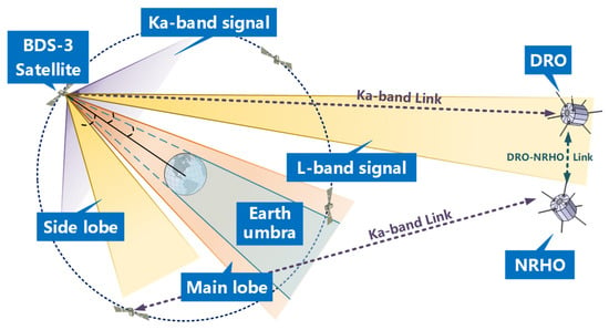
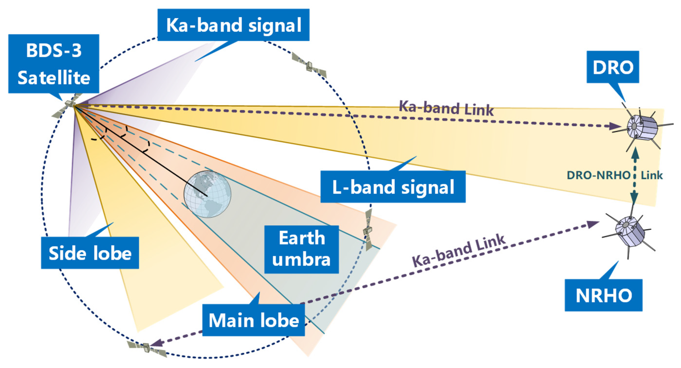
To address these limitations, this study proposes a BDS-3-based OD and TS framework that integrates L-band and Ka-band signals for spacecraft in cislunar space. Figure 1 presents the overall system architecture and the scope of this study. The combination of the wide coverage provided by L-band signals and the high ranging precision of Ka-band links helps mitigate poor observation geometry and enhance estimation accuracy. Since the availability of Ka-band observations and ISLs may vary among missions, this study evaluates the proposed approach under several representative configurations. The results provide guidance for the design and deployment of future cislunar navigation and timing systems.
Figure 1.
Architecture of OD and TS for DRO/NRHO based on BDS signals.
Compared with previous studies, the main contributions of this work are threefold: (1) A unified OD and TS framework integrating BDS L-band and Ka-band observations for spacecraft operating in DRO and NRHO is developed. (2) The impact of different Ka-band link configurations under realistic resource constraints is systematically evaluated. (3) The contribution of DRO–NRHO ISLs to OD and TS performance is quantitatively analyzed.
The remainder of this paper is organized as follows. Section 2 briefly introduces the Circular Restricted Three-Body Problem (CRTBP) and the algorithms for orbit determination and time synchronization based on BDS signals. Section 3 presents the simulation parameters in detail and provides an initial analysis of signal characteristics and visibility. Section 4 presents and discusses the orbit determination and time synchronization performance of DRO and NRHO under various experimental scenarios. Finally, conclusions and discussions are drawn in Section 5.
2. Principles and Algorithms
2.1. CRTBP
The three-body problem is complex, but in the Earth-Moon system, the problem can be simplified because the satellite’s mass is much smaller than that of the Earth and the Moon, and the center of mass of the Earth-Moon system remains constant. By introducing geometric and dynamic constraints, the problem is reduced to what is known as the CRTBP. The problem describes the motion of a massless particle (representing a satellite) due to the gravitational influence of two massive bodies (for the Earth-Moon system, these are the Earth and the Moon) with masses and , respectively, where [34].
In the Earth-Moon system, the satellite’s orbit is calculated within the Earth-Moon barycentric coordinate system. The origin of this coordinate system is at the center of mass of the Earth-Moon system. The positive X-axis is directed along the vector from the center of the Earth to the center of the Moon, the Z-axis is aligned with the angular momentum vector of the system, and the positive Y-axis completes the right-handed coordinate system.
Typically, the CRTBP is solved using normalized variables. The unit of length (marked as LU) is normalized by the distance from the Earth to the Moon, and the unit of time (marked as TU) is normalized by the orbital period of the two bodies about their common center of mass. The mass ratio μ can be defined as follows,
where and denote the masses of the Moon and the Earth, respectively. Then the total mass of the Earth–Moon system is normalized to 1, with the Moon’s mass being and the Earth’s mass being . The Earth and Moon are located at and in the Earth-Moon barycentric coordinate system after normalization.
Then, the distances from the satellite position to the Earth and the Moon in the barycentric coordinate system can be calculated as,
and
The equations of satellite motion in dimensionless form are,
where satellite velocity and acceleration vectors are denoted as and . Since the system is conservative, a pseudo-potential function can be defined, that is,
and Equation (4) can be rewritten as,
where , and . Let the satellite state vector be defined as , the first-order variational equations are derived and result in the vector differential equation,
where can be written as,
and is defined as,
with components are expressed as , and . And the satellite state transition matrix at epoch t can be calculated as,
which can be used for orbit integration and state estimation.
2.2. OD and TS Algorithm of Spacecraft Based on BDS Signals
The L-band–based OD algorithm has been widely applied in OD for LEO satellites. The pseudorange observation for the L-band signal received by spacecraft S in Earth-Moon space from the i-th BDS-3 satellite can be given by Equation (11),
where and are the position vectors of the spacecraft and the i-th BDS-3 satellite. and denote the clock offsets of the satellite clock and the spacecraft receiver, respectively. and represent the hardware delays of the satellite and the spacecraft receiver, respectively, while denotes the measurement noise encompassing multipath effects and thermal noise components. Different from the common pseudorange observation equation of the ground receiver, most of the BDS sidelobe signals in the Earth-Moon space are not affected by atmospheric delay, so the errors caused by the ionosphere and troposphere are not considered.
OD and TS based on ISL have been extensively studied for the constellation autonomous maintenance of the BDS [30,35]. Therefore, a brief description is provided here.
Assume there are two satellites, A and B. First, satellite A sends a ranging signal to satellite B. After receiving the signal at epoch , satellite B then sends a ranging signal back to satellite A, which is received at epoch . The obtained one-way ISL measurement pseudoranges and for the A-B and B-A links can be represented by the observation equations as shown in Equations (12) and (13), respectively.
where and represent the position vectors of satellite A and B at epoch , and the clock offset of satellite A and B is denoted as and . and represent the propagation times for the A-B and B-A links, respectively. The parameters and correspond to the hardware delays at the transmission and reception of satellite i, respectively. and represent the measurement noise for the A-B and B-A links, respectively. and denote the readings of the local hardware clocks onboard satellites A and B, respectively. After applying the corresponding clock corrections and , the observations are referred to the common system time , which can be expressed as follows:
The satellite position and clock offset are continuously changing during the signal propagation. The geometric distance terms contained in the two observations are nearly equal, while the clock-offset-related terms appear with opposite signs. Therefore, by using a linear combination of addition and subtraction, the distance terms related to the satellite positions and the clock offset terms can be decoupled, allowing the geometric distance and clock-offset components to be largely separated for subsequent estimation.
To achieve this, the observation combinations and are defined as the average and half-difference in two-way ranging observations, respectively, and can be expressed as follows:
where and represent the variations in clock offset of A and B during the signal propagation. represents the change in the inter-satellite distance during signal propagation.
It can be concluded that even though the distance and clock offset are decoupled using linear combinations, due to the continuous change in satellite positions and clock offsets during the signal propagation, observations still require the use of orbit prediction or linear fitting methods to obtain the changes in distance and clock offsets. It can be concluded that the accuracy of OD and TS using ISL is influenced by the orbit determination accuracy and the performance of the onboard atomic clocks.
Subsequently, the Kalman filter can be used to estimate the satellite state and clock offset. The state vector to be estimated is denoted as,
where and represent the satellite position and velocity, while and represent the clock offset and clock drift to be estimated. And denotes the solar radiation pressure coefficient. The corresponding state transition matrix can be written as,
where and is the state transition matrix of orbital dynamics, is the matrix of clock, where is a time interval and is a unit matrix.
After obtaining the state transfer matrix, the predicted state and covariance matrix at epoch time k can be expressed as,
where and are the estimated state and corresponding covariance matrix, respectively. is the covariance matrix of system noise and represents the accuracy of the dynamic model.
The measurement matrices and corresponding to the L-band and Ka-band are shown in Equations (21) and (22), respectively. Since the L-band pseudorange observation is a function of the satellite position and clock states only, it does not explicitly depend on the velocity state , the clock drift state , or the solar radiation pressure coefficient . Therefore, the corresponding partial derivatives are zero.
and
Then the measurement is updated, and the gain matrix , estimated state , and the covariance matrix can be calculated using,
where denotes the measurement innovation vector, is the observation matrix, and represents the predicted observation matrix computed from the predicted state. The gain matrix determines the weight of observation information when the state is updated. is the covariance matrix of observation noise. Then, the estimated state of the satellite can be solved.
3. Simulation Experiment and Preliminary Analysis
3.1. Satellite Orbits and Configuration
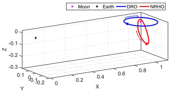
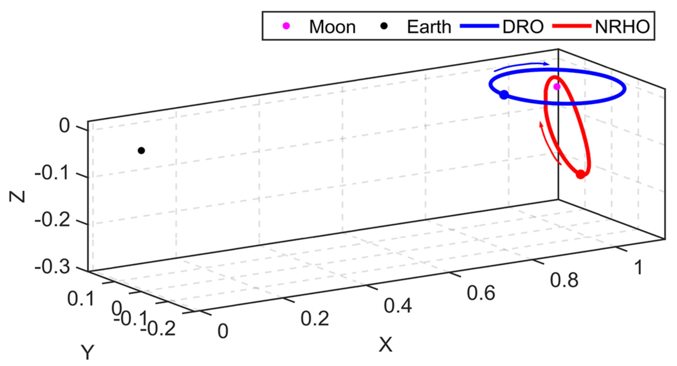
Considering the requirements for orbital stability and visibility of lunar communication and navigation satellites, DRO and NRHO have emerged as two representative cislunar orbital architectures, although their geometric characteristics differ significantly. The initial orbit parameters of the two orbits are listed in Table 1, and their corresponding paths are shown in Figure 2. The figure also shows the initial positions and directions of motion. As shown in Figure 2, the DRO is primarily distributed over low-latitude lunar regions, whereas the NRHO provides coverage concentrated near the lunar poles.
Table 1.
Initial orbit parameter of DRO and NRHO.
Figure 2.
Three-dimensional trajectories of DRO and NRHO in the Earth-Moon space.
For the satellite configuration, we adopt the setup described in [23], where the satellite is equipped with Earth-pointing L-band and Ka-band antennas. The carrier-to-noise ratio (C/N0) threshold for the L-band receiver is set to 15 dB-Hz. As for the on-board atomic clock, the clock propagation model is described by a quadratic polynomial [36,37]. We adopt the high-performance rubidium atomic clock proposed by literature [23] as the satellite clock in our simulation. Its power spectral density (PSD) and sampling interval are listed in Table 2.
Table 2.
Performance and PSD coefficients of the atomic clock.
3.2. Observation Simulation
Given the use of BDS L-band and Ka-band observations, the measurement simulation methods for both signal types are briefly introduced below. The L-band observation model has been extensively described in previous studies [20] and is therefore only summarized here. The fundamental principle is to estimate the C/N0 at the receiver based on the BDS satellites’ antenna pattern, the receiver antenna gain, and signal free-space propagation losses. Measurement noise is then determined according to the signal modulation scheme.
The pseudorange noise in L-band is related to the C/N0. The C/N0 (in dB-Hz) of the BDS receiver can be calculated as,
where is the output power of the transmitter amplifier, is the transmitter antenna gain, which relates to the elevation and azimuth, is receiving antenna gain related to the off-boresight angle, and represents the free space propagation loss. is the atmosphere influence and is set to 0 dB in our simulation due to the minor impact. denotes the noise power spectral density (in dBW/Hz) and can be calculated by,
where is the Boltzmann constant, and is the system noise temperature.
After the receiver C/N0 is obtained using Equation (26), the theoretical code noise can be calculated according to the signal modulation method. The thermal noise code tracking jitter can be calculated by Equation (27)
where is the code loop noise bandwidth in Hz, is the early-to-late correlator spacing in chips, is the carrier-to-noise ratio in dB-Hz. is the coherent integration time in seconds. The scaling coefficient k is typically assumed within the range of 0.6.
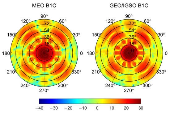
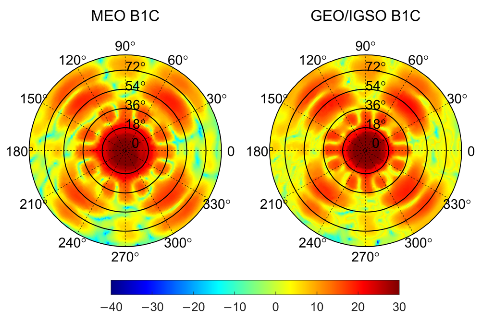
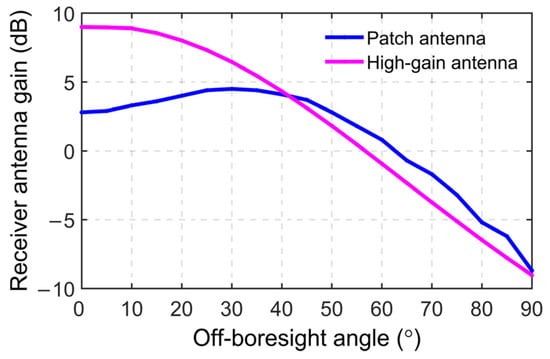
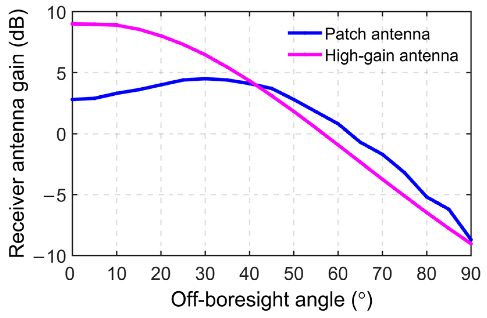
Accurate 3D antenna models are important for simulations. Therefore, the BDS-3 three-dimensional antenna model was adopted in this study. Figure 3 shows the Equivalent Isotropically Radiated Power (EIRP), which accounts for both the power amplifier output and the transmitting antenna gain. The BDS-3 B1C models can be obtained from literature [18]. It is noted that the antenna models of different types of satellites are different, such as GEO/IGSO and MEO satellites of BDS-3. The antenna gain of the BDS-3 receiver is shown in Figure 4.
Figure 3.
BDS antenna pattern of B1C.
Figure 4.
Receiver antenna gain.
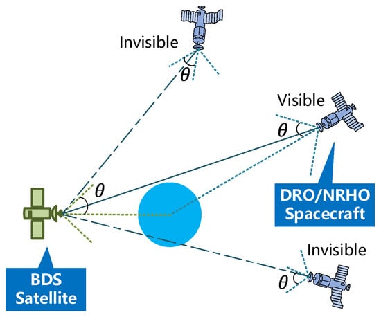
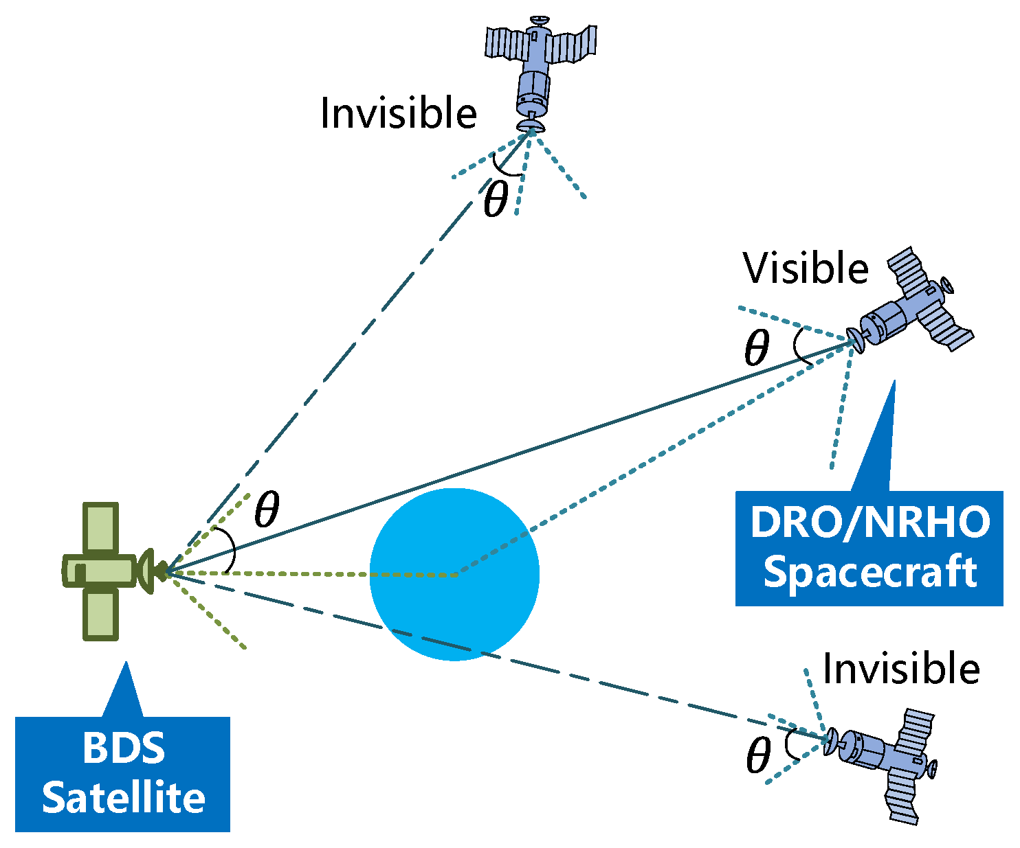
For Ka-band measurements, the mutual visibility between the transmitter and receiver must be ensured to support the two-way ranging strategy. Figure 5 illustrates the concept of inter-satellite two-way ranging. A communication link is considered available when the line of sight is unobstructed by celestial bodies and the satellite–spacecraft angle does not exceed the antenna beamwidth. The antenna beamwidth Θ is defined as 60 degrees in this study. The observation noise of the Ka-band signal is determined by the signal propagation distance d. When the propagation distance , the noise ; when , the noise ; and for , .
Figure 5.
Illustration of Ka-Band Visibility.
The BDS ISLs operate using a single-frequency time-division multiplexing scheme, in which each link is assigned a default 1.5 s transmission slot. This configuration is adequate for Earth orbit satellites, as the maximum propagation distance is around 70,000 km. It can reach up to 500,000 km in cislunar space, corresponding to a signal propagation delay of approximately 1.6 s, which exceeds the default time slot. We propose merging two adjacent slots (3.0 s total) for cislunar operations, which reduces the effective Ka-band sampling rate to 10 bidirectional links per minute. Even so, this is sufficient to meet the needs of cislunar spacecraft.
3.3. Visibility Analysis
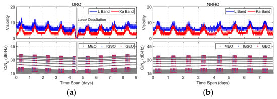
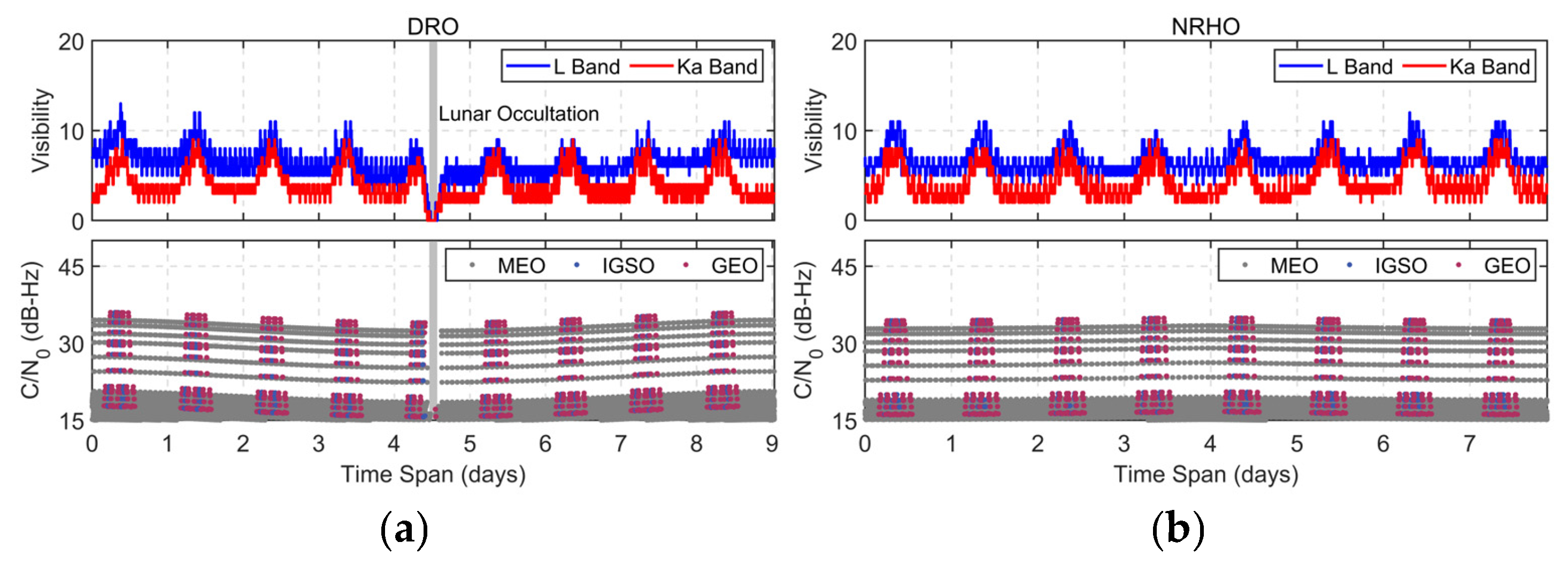
Based on the observation simulation methods described above, simulated L-band and Ka-band observations were generated for the DRO and NRHO orbits. Figure 6 shows the visibility and C/N0 variations in the L-band and Ka-band signals over one orbital period for the DRO and NRHO, respectively. In the visibility subplot, the blue and red curves denote the number of visible satellites for the L-band and Ka-band signals, respectively. In the C/N0 subplot, different colors distinguish the received signal strengths from BDS MEO, GEO, and IGSO satellites.
Figure 6.
(a) Satellite visibility (top) and L-band C/N0 (bottom) for DRO. (b) Satellite visibility (top) and L-band C/N0 (bottom) for NRHO.
It can be observed that both DRO and NRHO, being located near the Moon, exhibit similar numbers of visible satellites. However, their visibility characteristics differ due to orbital geometry. The DRO experiences lunar occultation with zero visible satellites, whereas the NRHO remains continuously tracked by BDS satellites. In addition, the number of visible satellites in the Ka-band is lower than that in the L-band, with the maximum visible satellites not exceeding 10. This allows the Ka-band sampling interval to reach 60 s, which is beneficial for OD and TS. Furthermore, the C/N0 of IGSO/GEO satellites is slightly higher than that of MEO satellites, primarily due to differences in antenna gain and radiation characteristics.
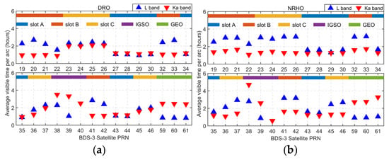
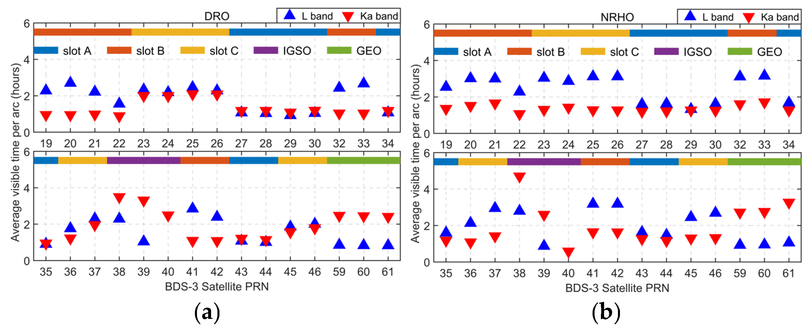
To evaluate the impact of long-duration continuous observations on OD performance, the visibility characteristics of different BDS satellite types for DRO and NRHO are further analyzed. Figure 7 illustrates the average visibility duration of each observation arc for DRO and NRHO orbits, respectively. Table 3 and Table 4 provide additional parameters, including the average visibility duration for L-band and Ka-band signals, total visible time in one orbital period, and the average visibility duration per arc. In Figure 7, the blue upward triangles denote the average L-band visibility duration, while the red downward triangles indicate the Ka-band results. Different BDS satellite types and orbital planes are also distinguished in the plot.
Figure 7.
(a) Average visibility duration per observation arc for DRO (b) Average visibility duration per observation arc for NRHO.
Table 3.
BDS Satellite Visibility for DRO.
Table 4.
BDS Satellite Visibility for NRHO.
The results indicate that IGSO satellites provide the longest average Ka-band visibility duration per arc among all satellite types, which is expected to improve OD performance. Therefore, IGSO satellites are preferred for ISL establishment under limited onboard resources. Furthermore, noticeable visibility differences are observed among the three MEO orbital planes during one orbital period of DRO and NRHO. MEO satellites in the Slot-A plane exhibit the highest overall visibility, while those in the Slot-B plane achieve the longest average visibility duration per arc among the three planes. Accordingly, when additional onboard resources are available, ISLs with MEO satellites in the Slot-A and Slot-B planes are recommended. These visibility differences are primarily attributed to orbital geometry, including the solar beta angle and Sun–Earth–Moon configuration.
Following observation simulations and visibility analysis, the performance analysis of OD and TS based on L-band and Ka-band signals is presented as follows.
4. Experimental Results and Analysis
Based on the previous analysis, OD and TS experiments were conducted for DRO and NRHO under three scenarios: L-band-only, Ka-band-only, and combined L-band and Ka-band links. The experimental setups are summarized in Table 5.
Table 5.
Experimental strategy.
The initial state error covariance matrix is constructed as a diagonal matrix, assuming no initial cross-correlation between state variables. The a priori standard deviations of the position components are set to 1 × 10⁵ m in all three directions, while those of the velocity components are set to 1 × 10² m/s. The initial clock bias and drift uncertainties are defined according to 1 × 10⁻⁵ s and 1 × 10⁻⁸ s/s.
The process noise is modeled using a white-noise acceleration model for orbital dynamics. The acceleration noise level is set within the range of 1 × 10⁻⁷ m/s2. And the process noise for the clock states is modeled as Equation (29).
where is the time interval. , and are PSD coefficients and have been defined in Table 2.
4.1. OD and TS Based on BDS Signals
4.1.1. Solution Results Based on L-Band
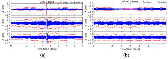
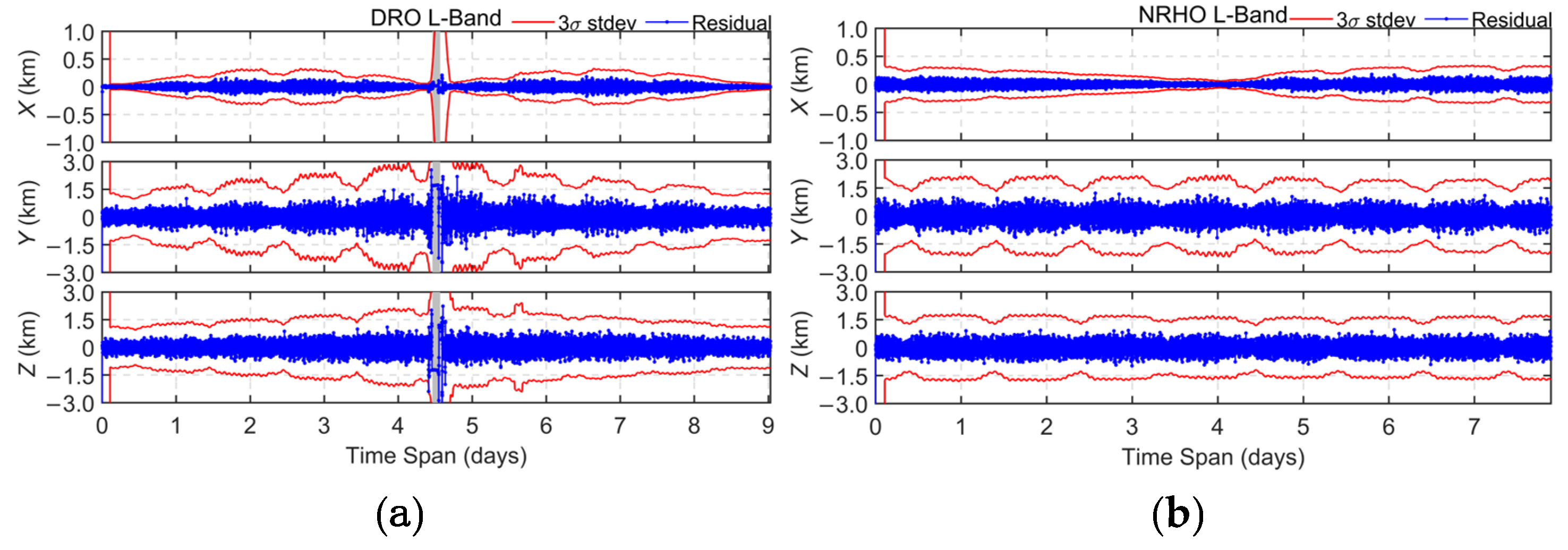
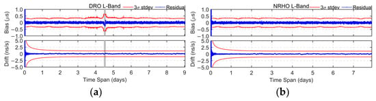
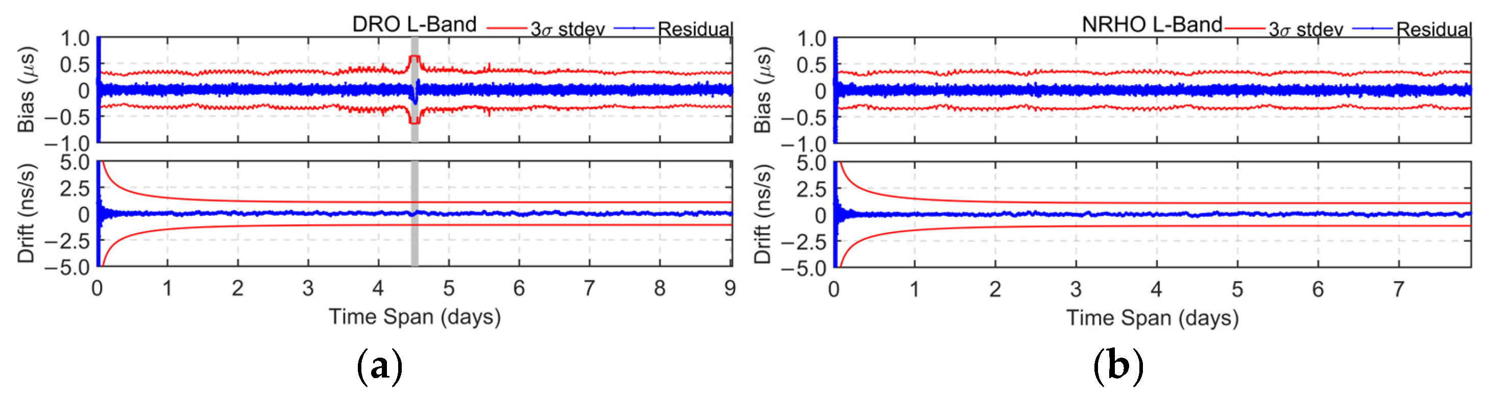
The OD and TS performance using BDS L-band-only links is first analyzed. Figure 8 and Figure 9 present the results for DRO and NRHO, respectively. The red curve denotes the 3σ bound, while the blue curve represents the OD and TS residuals. The statistical results are summarized in Table 6. RMS statistics are computed using only the steady-state post-convergence data, excluding the initial convergence phase, lunar occultation periods, and re-convergence intervals.
Figure 8.
(a) Orbit determination residuals for DRO using L-band observations; (b) Orbit determination residuals for NRHO cases using L-band observations.
Figure 9.
(a) Time synchronization results for the DRO using L-band observations; (b) Time synchronization results for the NRHO using L-band observations.
Table 6.
Statistical Results of Orbit determination and Time synchronization for DRO and NRHO Using L-Band Observations.
Lunar occultation in the DRO case leads to signal outages of approximately two hours per orbital period, resulting in significant degradation in OD performance. These periods are excluded from Table 6. The results show that the OD accuracy is on the order of hundreds of meters, while the TS accuracy is better than 30 ns, enabling only basic navigation capability. The OD and TS performance of NRHO is slightly inferior to that of DRO, mainly due to differences in orbital dynamics and observation geometry.
4.1.2. Solution Results Based on Ka-Band
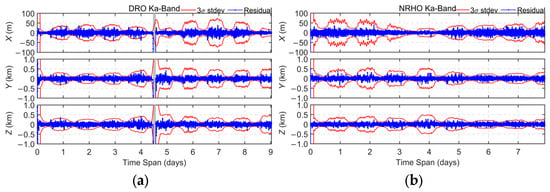
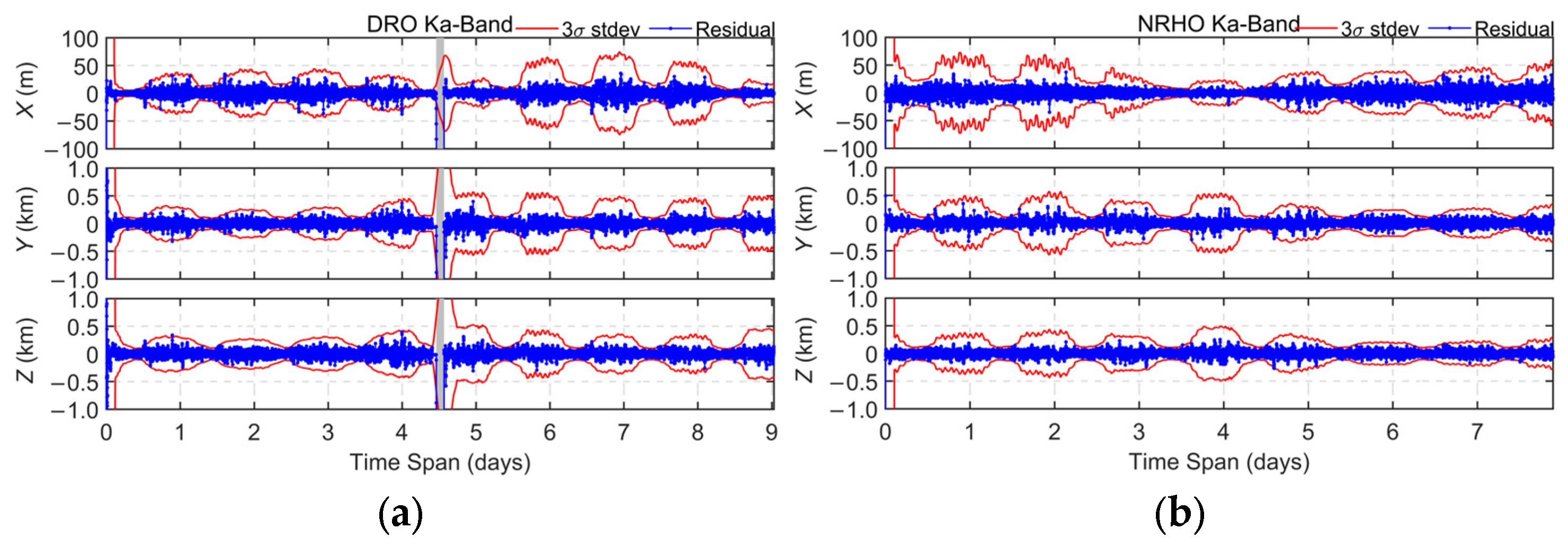
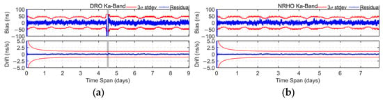
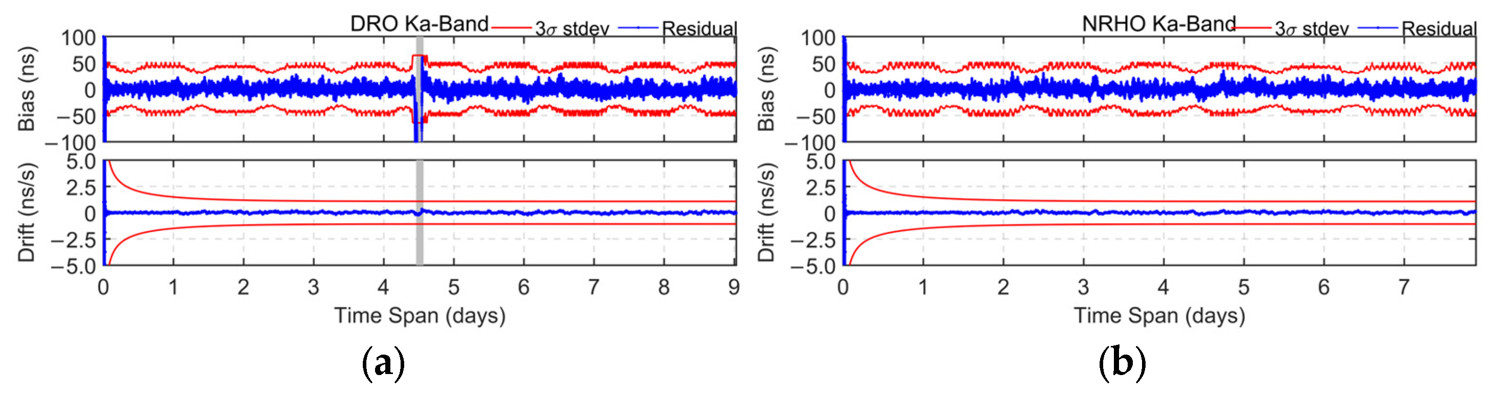
Like the L-band case, the OD and TS performance based on full BDS Ka-band links is analyzed. The results of OD and TS for DRO and NRHO are shown in Figure 10 and Figure 11, respectively. and the corresponding statistical results are listed in Table 7.
Figure 10.
(a) Orbit determination residuals for the DRO using Ka-band observations; (b) Orbit determination residuals for the NRHO cases using Ka-band observations.
Figure 11.
(a) Time synchronization results for the DRO using Ka-band observations; (b) Time synchronization results for the NRHO using Ka-band observations.
Table 7.
Statistical Results of Orbit determination and Time synchronization for DRO and NRHO Using Ka-Band Observations.
Although fewer Ka-band links are available than L-band observations, their substantially higher ranging precision results in superior OD performance. The OD accuracy for both DRO and NRHO is better than 100 m, while the TS accuracy is better than 10 ns. Consistent with the L-band results, the DRO achieves slightly better OD and TS performance than the NRHO.
4.1.3. Solution Results Based on L-Band and Ka-Band
The preceding results indicate that full Ka-band observations can provide high-precision OD and TS performance. However, implementing a complete Ka-band link architecture is challenging because of limited onboard resources. In contrast, although L-band observations are continuously available, their lower ranging precision limits the achievable OD and TS performance. To balance performance and resource constraints, L-band and Ka-band measurements are combined, while only selected Ka-band links are utilized. Accordingly, the following schemes are investigated. The initial weight ratio between L-band and Ka-band observations is set to 1:3. For brevity, only the RMS statistics are presented in Table 8 and Figure 12.
Table 8.
DRO and NRHO OD and TS statistical results for two schemes.
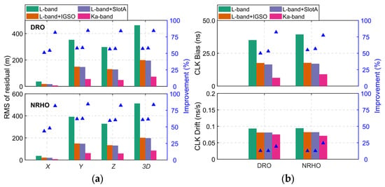
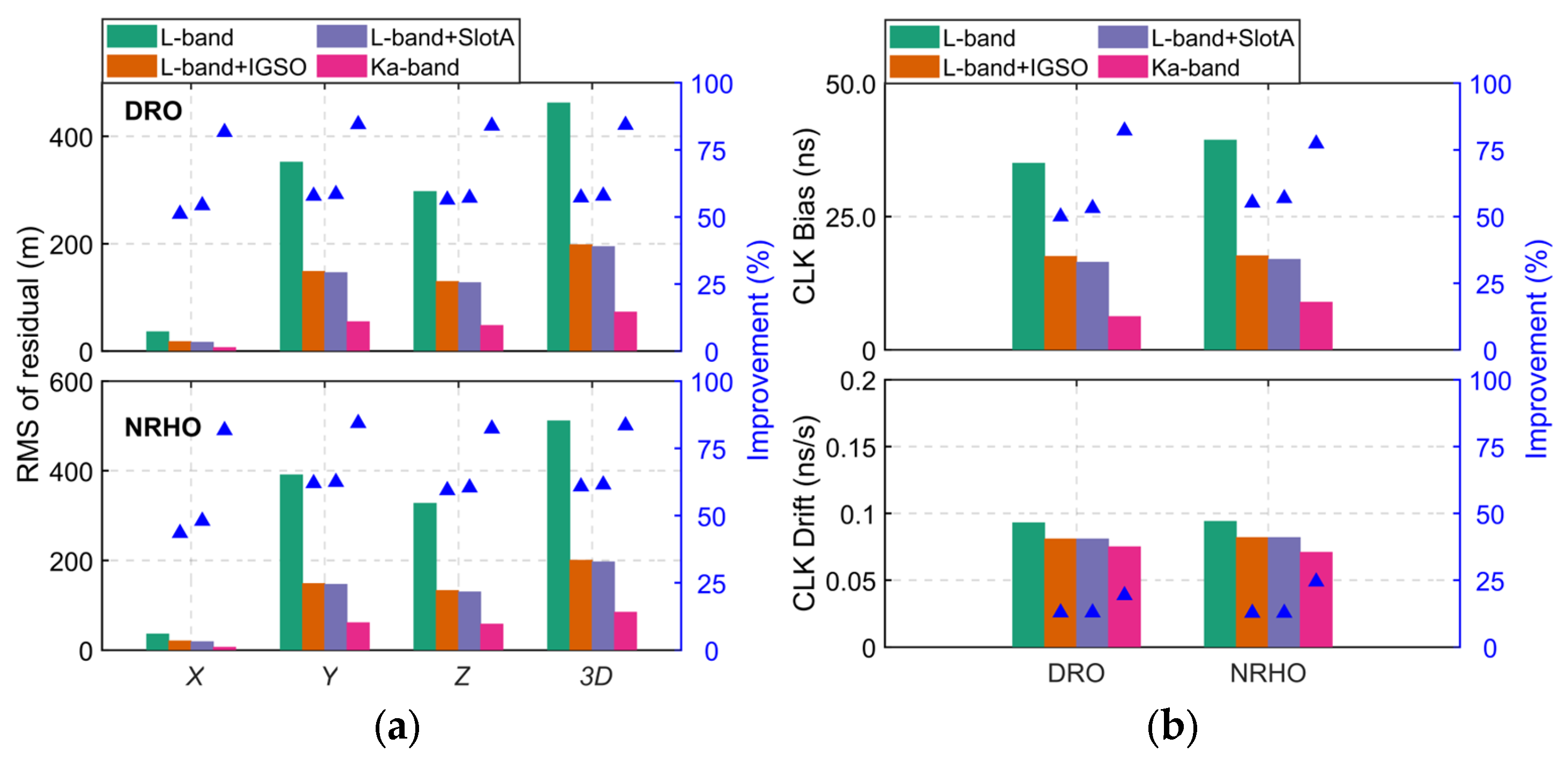
Figure 12.
(a) RMS errors of orbit determination and time synchronization for the DRO; (b) RMS errors of orbit determination and time synchronization for the NRHO.
Scheme 1 (S1): L-band observations combined with Ka-band observations from IGSO satellites, denoted as (L+IGSO).
Scheme 2 (S2): L-band observations combined with Ka-band observations from MEO satellites in Slot-A orbital plane, denoted as (L+ Slot-A).
The two schemes are selected according to the visibility and signal-quality analyses presented above. IGSO satellites exhibit the longest average Ka-band visibility duration per arc and higher C/N0 values, making them the preferred choice under limited link resources. In the MEO constellation, Slot-A provides the highest overall visibility and is therefore chosen as a representative case for evaluating MEO-based Ka-band augmentation performance.
Figure 12 also includes the results obtained using L-band-only and Ka-band-only observations, denoted as “L-band” and “Ka-band”, respectively, to facilitate comparison.
Compared with the L-band-only case, both S1 and S2 achieve substantial improvements in OD and TS performance. The OD accuracy is improved to approximately 200 m, while the TS accuracy is better than 20 ns.
For S1, the orbit accuracy is improved by 51.1%, 57.8% and 56.4% in the X, Y and Z directions, and 57.4% in the 3D direction. For S2, these are 54.3%, 58.5%, 57.1% and 57.9%, respectively. For TS, the clock bias and clock drift accuracies are improved by 50.0% and 12.9% for S1 and 53.1% and 12.9% for S2.
Overall, S2 achieves slightly better OD and TS performance than S1 because of the greater availability of Ka-band links. Although only a subset of Ka-band links is utilized, both schemes provide substantial performance gains compared with the L-band-only case. However, a noticeable gap remains relative to the full Ka-band configuration. These results demonstrate that integrating L-band and Ka-band observations is an effective approach for enhancing OD and TS performance in cislunar space.
4.2. OD and TS Based on BDS Signals and DRO-NRHO Link
The preceding results are based solely on BDS–DRO and BDS–NRHO links. However, additional DRO–NRHO inter-satellite links may further enhance OD and TS performance. Therefore, the OD and TS performance of a combined architecture incorporating both BDS–DRO/NRHO links and DRO–NRHO links is investigated.
To evaluate the contribution of DRO–NRHO ISL, four additional schemes are considered: L + ISL, All Ka + ISL, L + IGSO Ka + ISL, and L + Slot-A Ka + ISL. Here, “ISL” denotes the DRO–NRHO inter-satellite link.
4.2.1. Results Based on L-Band and ISL
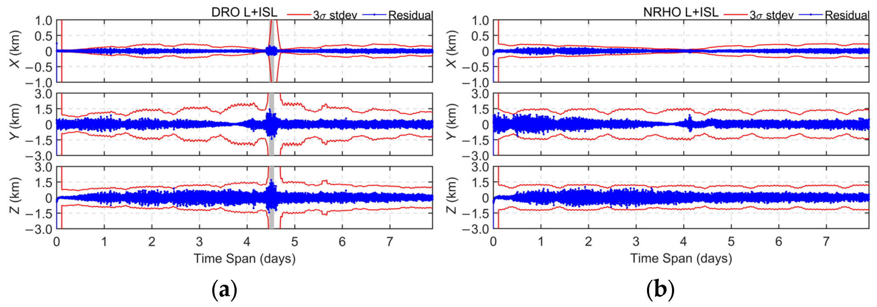
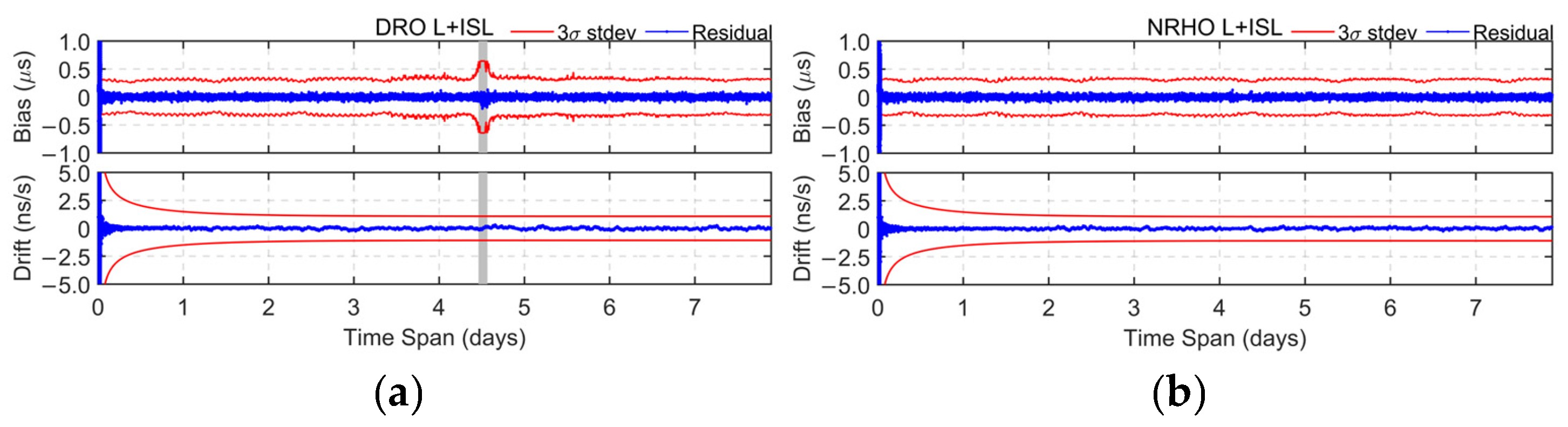
Figure 13 and Figure 14 present the OD and TS results for DRO and NRHO based on BDS L-band observations and DRO–NRHO ISL, while the corresponding statistics are summarized in Table 9. Compared with the L-band-only case, the inclusion of the DRO–NRHO link substantially enhances the OD and TS performance of both orbits. The OD accuracy improves from approximately 500 m to 300 m, corresponding to an improvement of about 41.0% for both DRO and NRHO. The TS accuracy remains better than 30 ns, with improvements of 23.4% and 21.5% for DRO and NRHO, respectively.
Figure 13.
(a) Orbit determination residuals for the DRO using L-band and DRO-NRHO link observations; (b) Orbit determination residuals for the NRHO using L-band and DRO-NRHO link observations.
Figure 14.
(a) Time synchronization residuals for the DRO using L-band and DRO-NRHO link observations; (b) Time synchronization residuals for the NRHO cases using L-band and DRO-NRHO link observations.
Table 9.
Statistical Results of Orbit determination and Time synchronization for DRO and NRHO Using L-Band and ISL.
Overall, the introduction of ISL significantly enhances both OD and TS performance in cislunar space. Compared with L-band-only observations, ISLs provide additional geometric diversity and improve solution robustness, particularly during lunar occultation periods when GNSS visibility is severely limited. The results demonstrate that ISL-based augmentation can effectively mitigate the degradation of navigation performance in weak-geometry environments, thereby improving both orbit determination and time synchronization accuracy for spacecraft operating in DRO and NRHO.
4.2.2. Results Based on Ka-Band and ISL
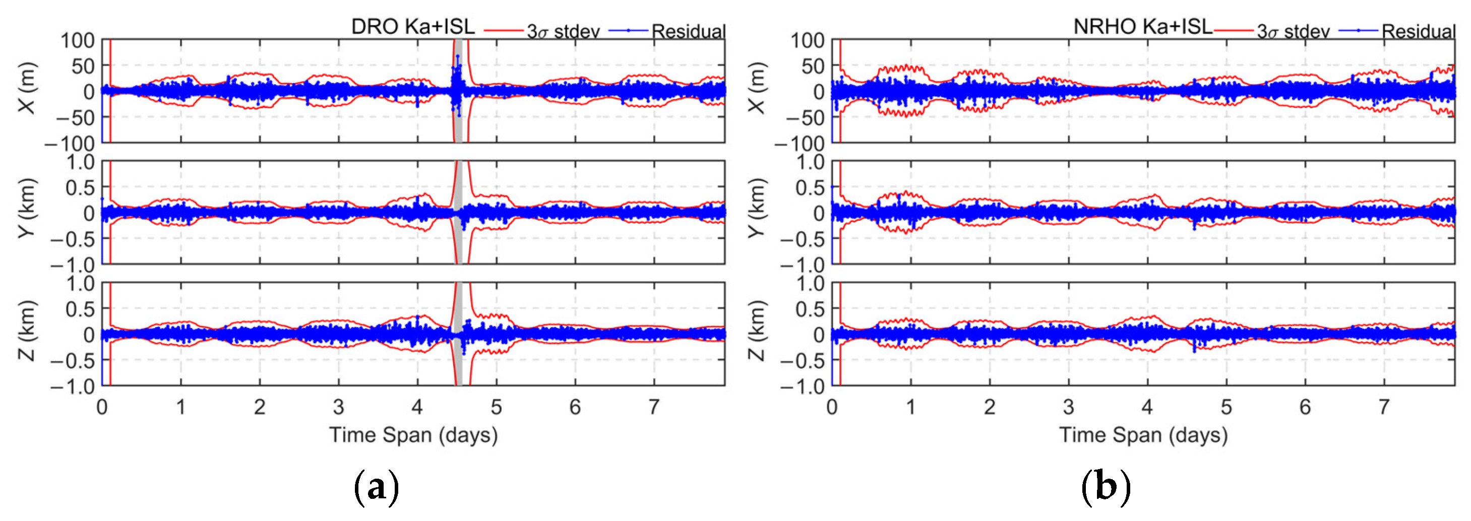
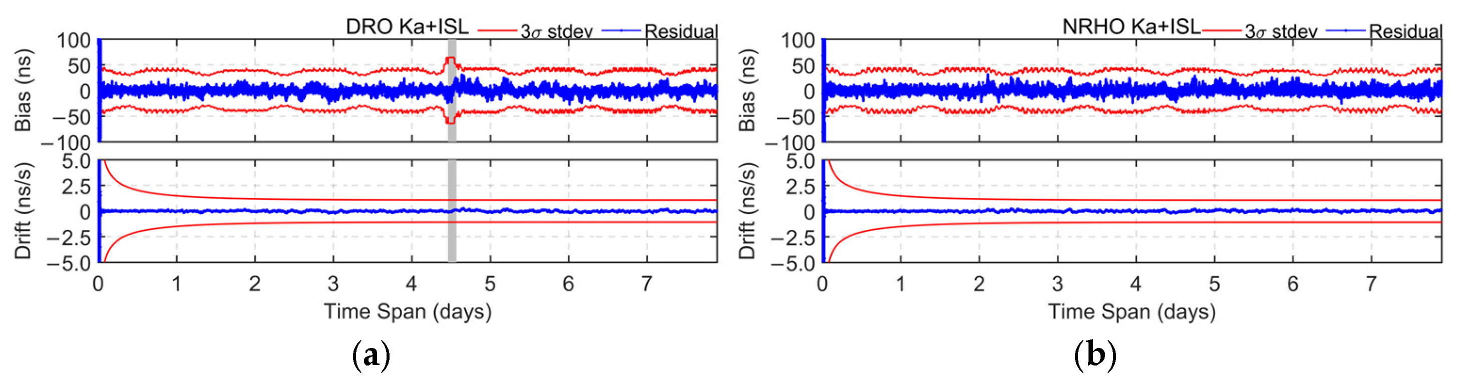
As shown in Figure 15 and Figure 16 and summarized in Table 10, the Ka + ISL scheme further improves OD and TS performance compared with the Ka-band-only case. The OD accuracy for DRO and NRHO is better than 65 m, corresponding to improvements of 12.7% and 25.9%, respectively. The TS accuracy reaches approximately 5 ns, representing an improvement of about 20%. Moreover, for DRO, the inclusion of the ISL effectively mitigates the degradation in OD and TS performance during lunar occultation periods.
Figure 15.
(a) Orbit determination residuals for the DRO using Ka-band and DRO-NRHO link observations; (b) Orbit determination residuals for the NRHO using Ka-band and DRO-NRHO link observations.
Figure 16.
(a) Time synchronization residuals for the DRO using Ka-band and DRO-NRHO link observations; (b) Time synchronization residuals for the NRHO using Ka-band and DRO-NRHO link observations.
Table 10.
Statistical Results of Orbit determination and Time synchronization for DRO and NRHO Using Ka-Band and ISL.
4.2.3. Results Based on L-Band, Ka-Band and ISL
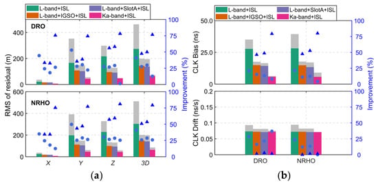
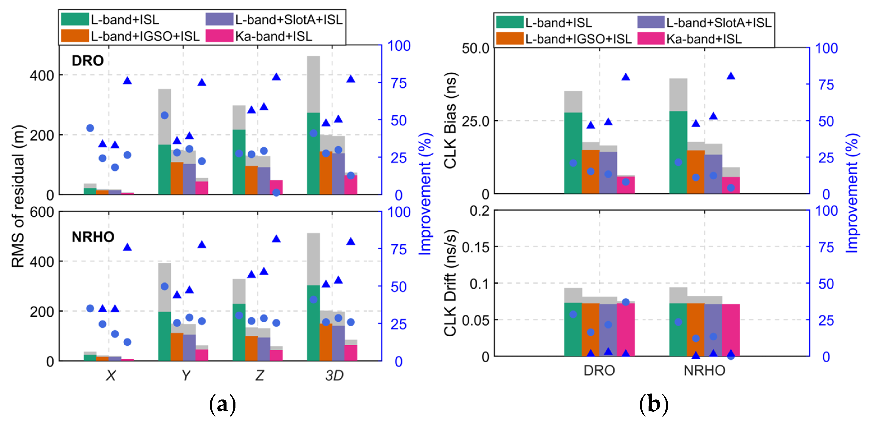
Figure 17 and Table 11 summarize the OD and TS results for the four schemes: L+ISL, all Ka + ISL, L + IGSO Ka + ISL, and L + SlotA Ka + ISL. For comparison purposes, the gray areas in Figure 17 represent the OD results of the corresponding schemes without ISL, consistent with Figure 12. While the slate-blue circular markers indicate the percentage improvements achieved after introducing DRO–NRHO inter-satellite links.
Figure 17.
(a) RMS errors of orbit determination and time synchronization for the DRO under four different schemes (b) RMS errors of orbit determination and time synchronization for the NRHO under four different schemes.
Table 11.
DRO and NRHO orbit determination and time synchronization statistical results for two schemes.
The results demonstrate that the integration of DRO–NRHO links improves both OD and TS performance for all four schemes. For the two configurations employing partial Ka-band links, namely L+IGSO Ka + ISL and L + SlotA Ka + ISL, the OD accuracy of both DRO and NRHO is improved to better than 150 m. Specifically, the DRO OD accuracy is improved by 27.5% and 29.9%, while the corresponding improvements for NRHO are 25.9% and 28.6%, respectively. In addition, the TS accuracy of both orbits is improved to better than 15 ns, with an average improvement of approximately 15%.
The accuracy enhancement is primarily attributed to the additional geometric constraints provided by the DRO–NRHO links. Compared with solutions relying solely on BDS satellites, the inclusion of the link enhances the observation geometry and increases measurement redundancy among cislunar spacecraft. Consequently, orbital state estimation becomes more robust, leading to improved OD accuracy. And the two-way ranging measurements provided by the ISLs contain direct clock information, enabling more accurate clock-state estimation and thereby improving TS performance.
Furthermore, the impact of ISL integration differs among the evaluated schemes. The largest improvement is observed for the L-band-only solution, reflecting the limited range precision of L-band observations. By comparison, the full Ka-band solution already achieves strong estimation performance owing to its high measurement accuracy and therefore benefits less from the addition of DRO–NRHO links. Even so, ISL integration still improves OD and TS performance by approximately 15%, confirming the effectiveness of ISLs even in the presence of high-precision Ka-band measurements.
Finally, based on the simulation results, the characteristics, advantages, limitations, and potential application scenarios of the schemes investigated are summarized in Table 12. The comparison provides guidance for selecting appropriate navigation and timing architectures for future Earth–Moon space missions.
Table 12.
Comparison of different navigation and timing schemes for Earth–Moon space missions.
The results indicate that different observation architectures provide distinct trade-offs between performance, implementation complexity, and deployment cost. For early-stage lunar missions, L-band observations alone can provide basic autonomous navigation capability with relatively low implementation cost. For long-term lunar infrastructure and navigation constellations, the integration of Ka-band links and ISLs can significantly improve OD and TS performance, enabling high-precision positioning and timing services. Therefore, the proposed framework offers a scalable solution that can support different stages of future cislunar PNT system development.
It should be noted that the presented results are obtained under the considered simulation assumptions and representative DRO/NRHO scenarios. Factors such as spacecraft maneuvers, hardware implementation errors, multi-sensor fusion, and future dedicated lunar navigation constellations are not considered and may affect the achievable performance in practical applications.
5. Conclusions and Discussion
DROs and NRHOs have emerged as two representative cislunar orbit families for future lunar exploration and navigation infrastructures. Considering the requirements for the construction of future lunar navigation constellations and the autonomous navigation performance of spacecraft, the OD and TS performance of DRO and NRHO based on BDS signals is analyzed.
- (1)
- L-band-only solutions yield relatively weak OD and TS performance, providing positional accuracy of approximately 500 m and time synchronization precision of 40 nanoseconds for spacecraft in DRO and NRHO orbits, which is acceptable for autonomous spacecraft navigation, but cannot meet the high-precision OD and TS requirements of the lunar navigation satellite system. If only a full Ka-band link is used, the OD accuracy can be better than 100 m. Considering the limited on-board resources, this scheme is difficult to implement. However, integrating L-band signals with partial Ka-band observations effectively enhances OD and TS accuracy within resource limitations.
- (2)
- In addition to adding some BDS Ka-band observations, DRO-NRHO links constitute an effective approach to enhance OD and TS performance. The OD and TS performance using L-band observations combined with partial Ka-band observations can achieve accuracy better than 150 m and 15 ns, respectively. The addition of the DRO-NRHO link provides a more effective means for autonomous navigation and time synchronization of lunar spacecraft. The orbit determination accuracy achieved using all Ka-band observations and ISL can be better than 65 m, while the time synchronization accuracy can be better than 5 ns, representing the highest performance among all the proposed schemes.
- (3)
- The results demonstrate that GNSS-based observations can serve as an effective enabling technology for the initial deployment phase of cislunar navigation infrastructure. Even in the absence of dedicated lunar navigation satellites, decameter- to hectometer-level navigation performance can be achieved, providing practical support for early cislunar exploration and infrastructure construction.
- (4)
- The achievable performance is fundamentally constrained by factors such as limited signal visibility, degraded observation geometry in cislunar space, and the intrinsic limitations of existing GNSS signal structures. Future work will focus on integrating dedicated lunar navigation satellites, multi-sensor fusion techniques, and advanced timing architectures to further improve cislunar PNT performance.
Author Contributions
D.W.: original draft, designed the experiments and analyzed the results for this study. T.X.: proposed the idea, theoretical guidance, and review. B.H.: original draft and review. S.W.: original draft and review. All authors have read and agreed to the published version of the manuscript.
Funding
This research was supported by the National Natural Science Foundation of China (Grant No. 42388102).
Data Availability Statement
The experimental solutions can be provided to readers by contacting the corresponding author.
Conflicts of Interest
The funders had no role in the design of the study; in the collection, analyses, or interpretation of data; in the writing of the manuscript; or in the decision to publish the results.
Abbreviations
The following abbreviations are used in this manuscript:
| DRO | Distant Retrograde Orbit |
| NRHO | Near-Rectilinear Halo Orbit |
| HEO | Highly Elliptical Orbit |
| LEO | Low Earth Orbit |
| NASA | National Aeronautics and Space Administration |
| OD | Orbit Determination |
| TS | Time Synchronization |
| MEO | Medium Earth Orbit |
| ISL | Inter-Satellite Link |
| GNSS | Global Navigation Satellite System |
| GPS | Global Positioning System |
| BDS | Beidou Navigation Satellite System |
| GEO | Geostationary Earth Orbit |
| IGSO | Inclined Geosynchronous Orbit |
| CRTBP | Circular Restricted Three-Body Problem |
| LU | Unit Length |
| TU | Unit Time |
| C/N0 | Carrier-to-Noise Ratio |
| PSD | Power Spectral Density |
References
- Burns, J.O.; Mellinkoff, B.; Spydell, M.; Fong, T.; Kring, D.A.; Pratt, W.D.; Cichan, T.; Edwards, C.M. Science on the Lunar Surface Facilitated by Low Latency Telerobotics from a Lunar Orbital Platform—Gateway. Acta Astronaut. 2019, 154, 195–203. [Google Scholar] [CrossRef] [Scilit]
- Indian Space Research Organisation, Department of Space VM3-M4-Chandrayaan-3 Mission. LVM3-M4-Chandrayaan-3 Mission. 2023. Available online: https://www.isro.gov.in/Chandrayaan3.html (accessed on 10 May 2026).
- Japan Aerospace Exploration Agency. Outcome for the Smart Lander for Investigating Moon (SLIM) ’s Moon Landing; Japan Aerospace Exploration Agency: Tokyo, Japan, 2024. [Google Scholar]
- China National Space Administrtion. Chang’e 6 Is Scheduled to Land on the Far Side of the Moon, Specifically in the South Pole-Aitken Basin, and Will Carry out Far-Side Sampling Work as Planned; China National Space Administrtion: Beijing, China, 2024.
- Chinese Academy of Sciences. China Has Successfully Built a Three-Star Constellation in Earth-Moon Space. Available online: https://www.cas.cn/cm/202504/t20250417_5064417.shtml (accessed on 15 June 2026).
- Qin, S.; Huang, Y.; Li, P.; Shan, Q.; Fan, M.; Hu, X.; Wang, G. Orbit and Tracking Data Evaluation of Chang’E-4 Relay Satellite. Adv. Space Res. 2019, 64, 836–846. [Google Scholar] [CrossRef] [Scilit]
- Zhang, L. Development and Prospect of Chinese Lunar Relay Communication Satellite. Space Sci. Technol. 2021, 2021, 3471608. [Google Scholar] [CrossRef] [Scilit]
- Advanced Space We Are At The Moon. Available online: https://advancedspace.com/missions/capstone/# (accessed on 15 June 2026).
- NASA Gateway. Available online: https://www.nasa.gov/mission/gateway/ (accessed on 15 June 2026).
- Hill, K.A. Autonomous Navigation in Libration Point Orbits. Ph.D. Thesis, University of Colorado at Boulder, Boulder, CO, USA, 2007. [Google Scholar]
- Critchley-Marrows, J.J.R.; Wu, X.; Kawabata, Y.; Nakasuka, S. Autonomous and Earth-Independent Orbit Determination for a Lunar Navigation Satellite System. Aerospace 2024, 11, 153. [Google Scholar] [CrossRef] [Scilit]
- Cao, J.; Man, H.; Wang, W.; Wang, J.; Liu, S.; Ju, B.; Zhang, Y. A Simulation Study of Orbit Determination Capability for Cislunar Space Probes Using ISL Data (in Chinese with English Abstract). Geomat. Inf. Sci. Wuhan Univ. 2023, 50, 637–646. [Google Scholar] [CrossRef]
- Pu, J.; Li, S.; Liu, J.; Guo, P.; Wang, W. Space-Based Orbit Determination and Time Synchronization Method for Three Typical Cislunar Orbits. J. Deep Space Explor. 2023, 10, 641–651, (In Chinese with English Abstract). [Google Scholar]
- Wang, D.; Xu, T.; Li, M.; Meng, Y.; Gao, W.; Cong, D.; Wang, S.; Shi, Y.; He, B. Lunar Navigation Satellite System for the South Pole and Earth–Moon Space: Constellation Design and Performance Evaluation with Integrated BDS. GPS Solut. 2025, 29, 87. [Google Scholar] [CrossRef] [Scilit]
- Huang, Y.; Yang, P.; Chen, Y.; Li, P.; Zhou, S.; Tang, C.; Hu, X. Orbit determination ofacislunar space probe using Inter-Satellite Link data. SciSin-Phys. Mech. Astron. 2023, 53, 229513, (In Chinese with English Abstract). [Google Scholar] [CrossRef] [Scilit]
- Delépaut, A.; Schönfeldt, M.; Giordano, P.; Blonski, D.; Sarnadas, R.; Ries, L.; Ventura-Traveset, J. A System Study for Cislunar Radio Navigation Leveraging the Use of Realistic Galileo and GPS Signals. In Proceedings of the 32nd International Technical Meeting of the Satellite Division of the Institute of Navigation, Miami, FL, USA, 16–20 September 2019; pp. 1199–1219. [Google Scholar]
- Delépaut, A.; Giordano, P.; Ventura-Traveset, J.; Blonski, D.; Schönfeldt, M.; Schoonejans, P.; Aziz, S.; Walker, R. Use of GNSS for Lunar Missions and Plans for Lunar In-Orbit Development. Adv. Space Res. 2020, 66, 2739–2756. [Google Scholar] [CrossRef] [Scilit]
- Lin, K.; Zhan, X.; Yang, R.; Shao, F.; Huang, J. BDS Space Service Volume Characterizations Considering Side-Lobe Signals and 3D Antenna Pattern. Aerosp. Sci. Technol. 2020, 106, 106071. [Google Scholar] [CrossRef] [Scilit]
- Guan, M.; Xu, T.; Li, M.; Gao, F.; Mu, D. Navigation in GEO, HEO, and Lunar Trajectory Using Multi-GNSS Sidelobe Signals. Remote Sens. 2022, 14, 318. [Google Scholar] [CrossRef] [Scilit]
- Iiyama, K.; Vila, G.C.; Gao, G. LuPNT: Open-Source Simulator for Lunar Positioning, Navigation, and Timing. In Proceedings of the 36th International Technical Meeting of the Satellite Division of the Institute of Navigation, Denver, CO, USA, 11–15 September 2023; pp. 1499–1510. [Google Scholar]
- Iiyama, K.; Kawabata, Y.; Funase, R. Autonomous and Decentralized Orbit Determination and Clock Offset Estimation of Lunar Navigation Satellites Using GPS Signals and Inter-Satellite Ranging. In Proceedings of the 34th International Technical Meeting of the Satellite Division of the Institute of Navigation, St. Louis, MO, USA, 20–24 September 2021; pp. 936–949. [Google Scholar]
- Winternitz, L.B.; Bamford, W.A.; Long, A.C.; Hassouneh, M. GPS Based Autonomous Navigation Study for the Lunar Gateway. In Proceedings of the Annual American Astronautical Society (AAS) Guidance, Navigation, and Control Conference, Breckenridge, CO, USA, 1–6 February 2019; Volume 169, pp. 585–600. [Google Scholar]
- Wang, D.; Xu, T.; Li, M.; Shi, Y. Navigation Performance Analysis of Earth–Moon Spacecraft Using GNSS, INS, and Star Tracker. Satell. Navig. 2024, 5, 16. [Google Scholar] [CrossRef] [Scilit]
- Capuano, V.; Basile, F.; Botteron, C.; Farine, P.-A. GNSS-Based Orbital Filter for Earth Moon Transfer Orbits. J. Navig. 2016, 69, 745–764. [Google Scholar] [CrossRef] [Scilit]
- Capuano, V.; Shehaj, E.; Botteron, C.; Blunt, P.; Farine, P.-A. GNSS/INS/Star Tracker Integration for Real-Time On-Board Autonomous Orbit and Attitude Determination in LEO, MEO, GEO and Beyond. In Proceedings of the 68th International Astronautical Congress, Adelaide, Australia, 25–29 September 2017. [Google Scholar]
- Parker, J.J.K.; Dovis, F.; Anderson, B.; Ansalone, L.; Ashman, B.; Bauer, F.H.; D’Amore, G.; Facchinetti, C.; Fantinato, S.; Impresario, G.; et al. The Lunar GNSS Receiver Experiment (LuGRE). In Proceedings of the 2022 International Technical Meeting of the Institute of Navigation, Long Beach, CA, USA, 25–27 January 2022; pp. 420–437. [Google Scholar]
- NASA. NASA Successfully Acquires GPS Signals on Moon. Available online: https://www.nasa.gov/directorates/somd/space-communications-navigation-program/nasa-successfully-acquires-gps-signals-on-moon/?utm_source=chatgpt.com (accessed on 15 June 2026).
- Yang, Y.; Yang, Y.; Hu, X.; Chen, J.; Guo, R.; Tang, C.; Zhou, S.; Zhao, L.; Xu, J. Inter-Satellite Link Enhanced Orbit Determination for BeiDou-3. J. Navig. 2020, 73, 115–130. [Google Scholar] [CrossRef] [Scilit]
- Li, X.; Hu, X.; Guo, R.; Tang, C.; Liu, S.; Xin, J.; Guo, J.; Tian, Y.; Yang, Y.; Yang, J.; et al. Precise Orbit Determination for BDS-3 GEO Satellites Enhanced by Intersatellite Links. GPS Solut. 2023, 27, 8. [Google Scholar] [CrossRef] [Scilit]
- Guo, L.; Wang, F.; Gong, X.; Sang, J.; Liu, W.; Zhang, W. Initial Results of Distributed Autonomous Orbit Determination for Beidou BDS-3 Satellites Based on Inter-Satellite Link Measurements. GPS Solut. 2020, 24, 72. [Google Scholar] [CrossRef] [Scilit]
- Xia, F.; Zhou, S.; Li, Z.; Jiang, N.; Hu, X. Analysis of Long-Term Distributed Autonomous Orbit Determination for BeiDou-3 Satellites. J. Geod. 2024, 98, 52. [Google Scholar] [CrossRef] [Scilit]
- Teng, Y.; Xu, B.; Gao, Y.; Liu, J.; Li, X. Autonomous Orbit Determination, Timekeeping and Service Performance Analysis of the Cislunar Space Navigation System Based on Special Long-Period Orbits. Measurement 2025, 255, 118005. [Google Scholar] [CrossRef] [Scilit]
- Yang, Y.; Yao, Z.; Mao, Y.; Xu, T.; Wang, D. Resilient Satellite-Based PNT System Design and Key Technologies. Sci. China Earth Sci. 2025, 68, 669–682. [Google Scholar] [CrossRef] [Scilit]
- Murray, C.D.; Dermott, S.F. Solar System Dynamics; Cambridge University Press: Cambridge, UK, 1999. [Google Scholar]
- Cheng, J.; Liu, W.; Zhang, X.; Wang, F.; Li, Z.; Tang, C.; Pan, J.; Chang, Z. On-Board Validation of BDS-3 Autonomous Navigation Using Inter-Satellite Link Observations. J. Geod. 2023, 97, 71. [Google Scholar] [CrossRef] [Scilit]
- Hutseil, T. Relating the Hadamard Variance to Mcs Kalman Filter Clock Estimation. In Proceedings of the 27th Annual Precise Time and Time Interval Systems and Applications Meeting, San Diego, CA, USA, 29 November–1 December 1995; pp. 291–302. [Google Scholar]
- Zucca, C.; Tavella, P. The Clock Model and Its Relationship with the Allan and Related Variances. IEEE Trans. Ultrason. Ferroelect. Freq. Contr. 2005, 52, 289–296. [Google Scholar] [CrossRef] [Scilit] [PubMed]

Disclaimer/Publisher’s Note: The statements, opinions and data contained in all publications are solely those of the individual author(s) and contributor(s) and not of MDPI and/or the editor(s). MDPI and/or the editor(s) disclaim responsibility for any injury to people or property resulting from any ideas, methods, instructions or products referred to in the content. |
© 2026 by the authors. Licensee MDPI, Basel, Switzerland. This article is an open access article distributed under the terms and conditions of the Creative Commons Attribution (CC BY) license.