


Abstract
This study investigates the application of advanced metal additive manufacturing (AM) and topology optimization for the development of a structurally efficient and lightweight 3U nanosatellite frame. Payload weight is a critical factor in space mission costs; therefore, a stock 3U CubeSat design was subjected to structural optimization using specialized Generative Design Software. The optimized model was fabricated using Powder Bed Fusion—Direct Metal Laser Sintering (PBF-DMLS) on an EOS M290 metal printer with AlSi10Mg aluminum alloy. While AlSi10Mg differs in ultimate tensile strength from traditional wrought aerospace alloys, it was selected to evaluate the baseline feasibility of this application. To evaluate manufacturability and preliminary performance, Finite Element Analysis (FEA), including structural and modal response analyses, was conducted. While the optimized design successfully achieved a 53% mass reduction (from 333 g to 155 g) and met the 30 Hz minimum fundamental frequency requirement, static analysis indicated a maximum simulated stress of 287 MPa. Because this exceeds the material’s nominal yield strength of 220 MPa, localized plastic deformation is predicted in the bare-frame configuration under maximum launch loads. This necessitates further design iterations and full-assembly simulations, incorporating the load-sharing effects of integrated panels prior to physical qualification. Post-processing successfully met JAXA dimensional and surface roughness requirements. Ultimately, this study serves as a foundational manufacturability baseline, demonstrating the applicability of PBF-DMLS for nanosatellites.
1. Introduction
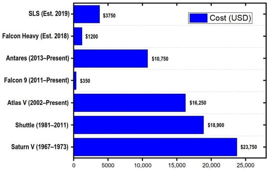
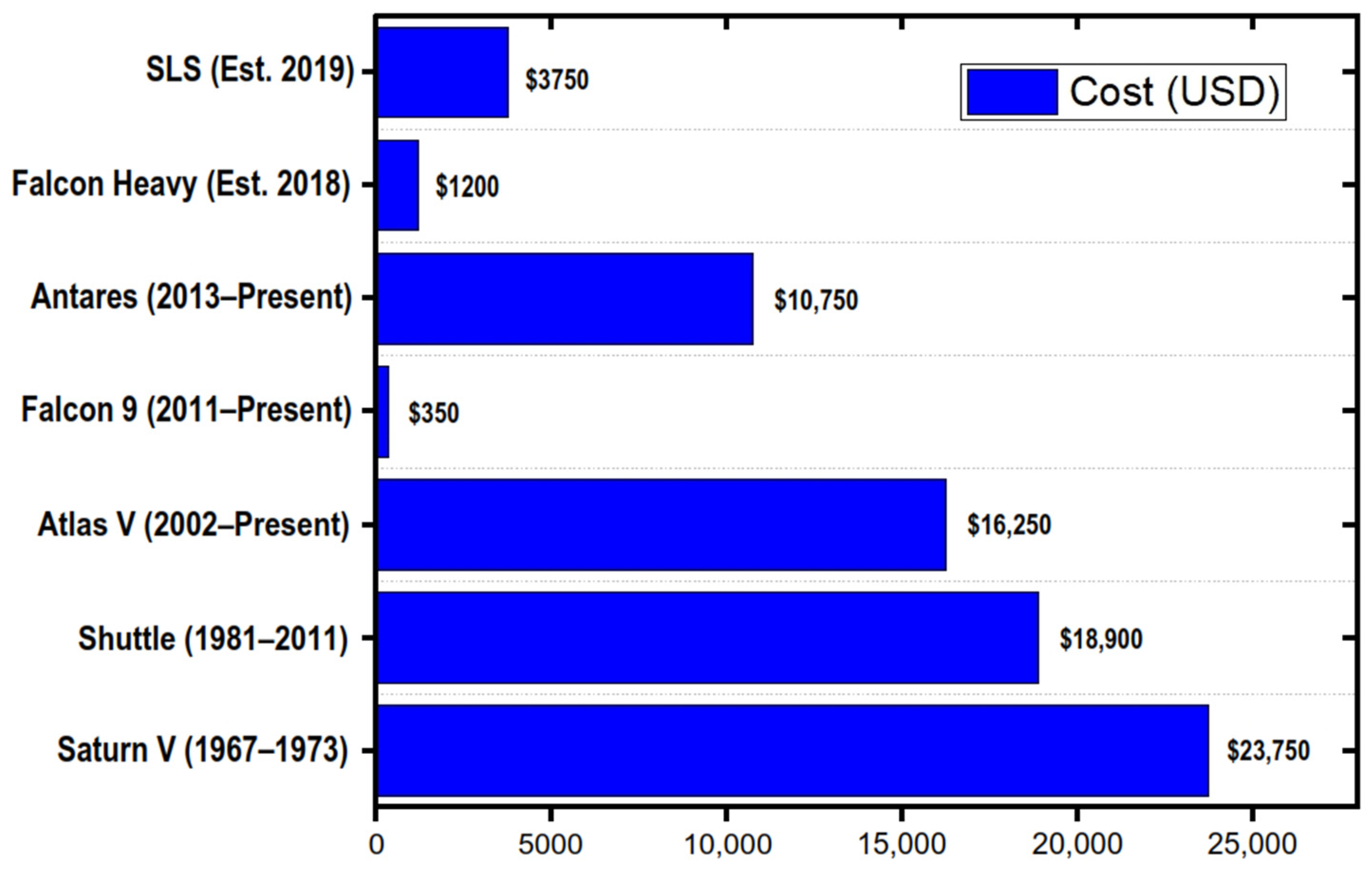
Payload weight is directly proportional to the cost of space missions and services. To mitigate these expenses, the aerospace industry is increasingly turning to advanced manufacturing techniques to develop lightweight, structurally efficient satellite components. This global shift is demonstrated by the rapid expansion of international micro- and nano-satellite roadmaps, as shown in Figure 1, such as those detailing the comprehensive initiatives of the Italian Space Agency (ASI) [1]. ASI has established dedicated programs to fund a diverse spectrum of new missions, ranging from telecommunications for the Internet of Things (IoT) to Earth observation and planetary exploration. Furthermore, these platforms are now capable of highly advanced operations. For instance, distributed radar networks, such as the RODiO mission concept, utilize clusters of formation-flying CubeSats to perform multi-static beamforming, significantly improving the Signal-to-Noise Ratio (SNR) to achieve high-quality Synthetic Aperture Radar (SAR) imaging [2]. Alongside these complex imaging capabilities, modern nanosatellites can execute fast orbital reconfiguration maneuvers utilizing innovative high-thrust hybrid rocket engines [3]. Achieving these advanced capabilities within strict mass constraints requires transitioning from traditional subtractive manufacturing to additive manufacturing (AM). AM enables the fabrication of complex, topology-optimized geometries that significantly reduce payload weight without compromising structural integrity.
Figure 1.
Satellite launch costs per kilogram to low-earth orbit (LEO).
In the Philippines, some of the major challenges for the country which can benefit from the growth of the space industry are disaster risk reduction management, environmental monitoring, development of high-value industries, and other applications. Cube satellites (or CubeSats for short) are miniaturized spacecraft which serve as an economic platform for countries and industry players to launch payloads and conduct research in space. The Philippines has an established presence in this arena, having launched its first CubeSat, Maya-1, in 2018. While Maya-1 has already re-entered Earth’s atmosphere, several sister craft have been launched since and remain in orbit. Together, they have served as platforms to test a variety of technologies, including but not limited to imaging technology, magnetic field measurement, GPS, and Store-and-Forward (S&F) capability. The heritage of this 3U CubeSat was based on the output designed up to the Preliminary Design Review (PDR) from the InDUS3Us initiative of PhilSA, which culminated in December 2022. The design reference utilizes the open-source BIRDS bus platform [4,5]. This was a deliberate decision, as the Philippines has been part of the BIRDS program since 2016 and possesses significant experience utilizing this bus through the Maya cube satellites. Concurrently, pioneer CubeSats utilizing alternative manufacturing materials, such as MakerSat-1, have proven the viability of non-traditional frame construction in orbit.
The fundamental architecture of these spacecraft stems from the CubeSat standard, originally introduced at the turn of the millennium as a new generation of picosatellites intended to facilitate low-cost space experimentation and education [6]. The concurrent development of standard deployers revolutionized access to space, ensuring that secondary payloads could be safely integrated with primary launch vehicles [7]. Consequently, the industry witnessed rapid growth, with statistical analyses of the first hundred deployed CubeSats highlighting their successful transition from purely educational tools to highly capable scientific platforms [8]. CubeSats are built to standard dimensions (Units or “U”) of 10 cm × 10 cm × 10 cm in size. They can be made of a single unit (1U) or a combination of multiple units (up to a maximum of 24U) [9]. Upon completion of the units, CubeSat manufacturers turn to third-party launch providers. In the Philippines’ case, this would be the Japan Aerospace Exploration Agency (JAXA). JAXA has a published set of guidelines that developers must adhere to before launch [10]. Table 1 summarizes the standard features requirements of a 3U CubeSat frame.
Table 1.
Requirements for a 3U CubeSat frame.
To meet these strict launch requirements while mitigating payload costs, the aerospace industry is increasingly turning to advanced manufacturing techniques. One of the main reasons for applying additive manufacturing (AM) to aerospace is weight reduction. With launch costs dependent on required fuel, lesser weight means less cost. Topology optimization technology is particularly helpful in this area, as it conducts simulations on parts and products to reduce their total volume to only what is necessary. These results typically end with organic-looking structures, which AM can fabricate at a comparatively lower cost compared to traditional manufacturing due to the complexity of the geometry.
Recent literature highlights the growing success of these methods in space hardware. Orme et al. [11] described three case studies for metal satellite parts, one of which was a star tracker camera baffle bracket. A cyclic approach between topology optimization and verification through vibration modeling tests was conducted. The finished part, produced using Direct Metal Laser Sintering (DMLS) with AlSi10Mg, achieved a 79% mass reduction while satisfying the same performance parameters as its predecessor design. Similarly, nTopology [12] worked with the US Air Force Institute of Technology to develop an optimized CubeSat bus frame. The software generated several infill options, with the final structure being a gyroid infill with a 250-micron shell. This resulted in a 50% weight reduction and a reduction in assembly parts from 150 to 25. This bus structure was manufactured with Inconel 718 for its stiffness.
Beyond metal alloys, other materials have also been explored for CubeSat technologies since the 2010s. Pioneer CubeSats include the Tomsk TPU-120 [13] and the MakerSat-1. Both of these craft utilize bodies made of polymeric materials, with MakerSat-1’s main mission being to determine the polymeric mass loss of four materials (PLA, ABS, Nylon, PEI) in a space environment.
Building upon these precedents, this study investigates the application of advanced metal AM and topology optimization specifically for the development of a structurally efficient, lightweight 3U nanosatellite frame using AlSi10Mg. The objective is to evaluate the viability of this optimized, printed frame against JAXA’s strict operational and dimensional tolerances [10].
2. Materials and Methods
2.1. Material Selection and Characterization
JAXA’s JEM Payload Accommodation Handbook—Vol. 8 [10] strictly specifies the use of machined 6061 or 7075 aluminum for the main body material. However, due to machine availability (EOS M290 manufactured by Electro-Optical Systems (EOS) GmbH from Munich, Germany) and the desire to leverage the geometric freedom of additive manufacturing, AlSi10Mg powder was selected. AlSi10Mg is a widely used AM aluminum alloy that closely replicates the properties of 6061-T6. A comparison of these mechanical properties is detailed in Section 3.
While AlSi10Mg does not meet the material specification clause of JAXA, the structural performance requirements (load-bearing capacity under 18.1 g) are satisfied through topology optimization. Consequently, this work claims compliance strictly with JAXA’s dimensional, surface roughness, and functional interface requirements, rather than the base material clause.
2.2. Simulation and Structural Optimization
Structural optimization and subsequent verification were performed using MSC Apex Generative Design 2023.3 Software. The primary constraints were derived from JAXA’s Small Satellite Deployment Interface Control Document.
To ensure the 3U CubeSat frame could withstand the rigorous launch environment while maximizing mass reduction, a two-phase computational approach was employed: structural topology optimization followed by comprehensive Finite Element Analysis (FEA) for validation.
2.2.1. Topology Optimization Parameters
Structural optimization and lightweighting of the baseline 3U frame were performed using generative design methodologies. The optimization algorithm was constrained by the physical requirements of the launch vehicle deployment mechanism. The primary boundary conditions and input parameters included:
- Fixturing points were established along the x, y and z axes. Critical interface geometries such as the mounting holes, mating points, and the exterior sliding faces required for deployment were strictly excluded from material removal to preserve functional integrity.
- The model was subjected to a simulated external force equivalent to 18.1 g of acceleration uniformly applied across all directions. This specific value represents the greatest quasi-static acceleration load of the Launch Vehicle Orbital Cygnus. By optimizing the frame for this maximum expected load, the satellite is engineered to withstand the environments of all other available launch vehicles.
- The optimization was driven by a target Factor of Safety (FoS) of 2.0. The material properties assigned to the generative algorithm were based on the nominal values of the selected AlSi10Mg alloy. Iterative material removal was controlled by a user-defined strut density set to medium, shape quality set to balanced, a complexity setting of 30 and manufacturing method set to “Metal AM” to ensure the resulting organic geometry remained manufacturable via powder bed fusion.
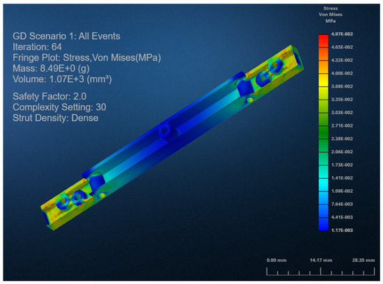
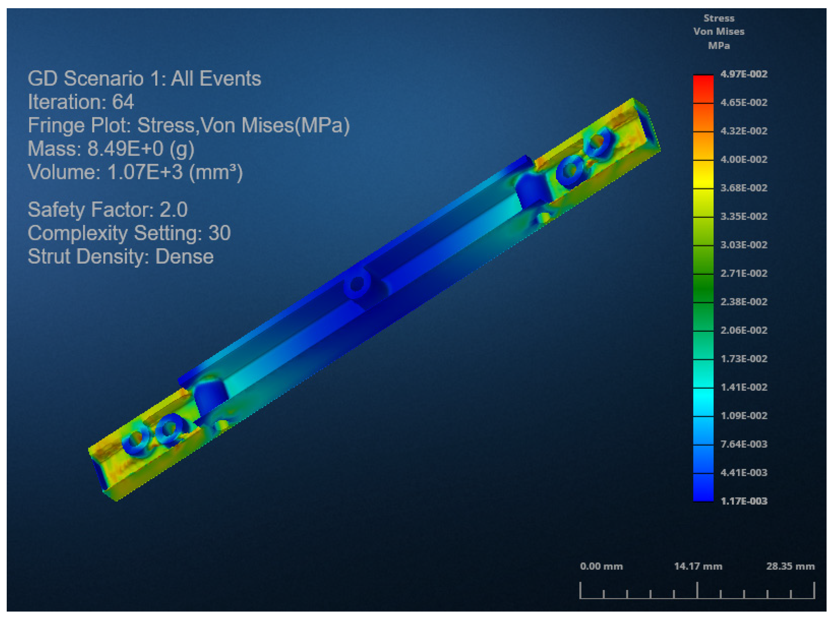
Figure 2 shows an iteration of the crossbar component of the CubeSat during an ongoing topology optimization. The color scale indicates regions where stress are either high (red) or low (blue), which is used by the software to decide which parts can be reduced and which ones will need to be thickened in the succeeding iteration steps.
Figure 2.
Topology optimization of the component struts of the 3U CubeSat frame.
The generative algorithm was driven by an objective function designed to minimize structural mass while maintaining a minimum Factor of Safety of 2.0. However, the raw, organic mesh models generated directly by the topology optimization software often contain acute stress concentrators, uneven wall thicknesses, and severe overhangs that are detrimental to manufacturability. To address this discrepancy between the theoretical optimized design and a practically fabricated structure, the outputs were imported into a Solidworks 2024 3D CAD environment for manual smoothing and refinement. This crucial step improves powder bed fusion (PBF) printability by normalizing the geometry. It is important to emphasize that these final, manually edited CAD models—not the raw generative outputs—were the exact geometries subjected to the subsequent FEA validation, ensuring that the simulated mechanical performance accurately reflects the physical, fabricated frame.
2.2.2. Finite Element Analysis (FEA) Validation
Following the generation of the optimized geometry, a rigorous FEA was conducted to evaluate the structural, modal, and harmonic responses of the assembly under simulated operational conditions. The FEA model incorporated the effects of assembly connections and the specific bolt pre-tensions required for integration.
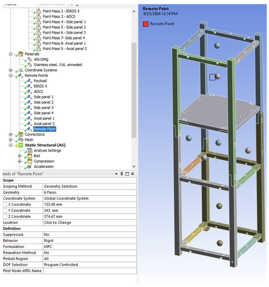
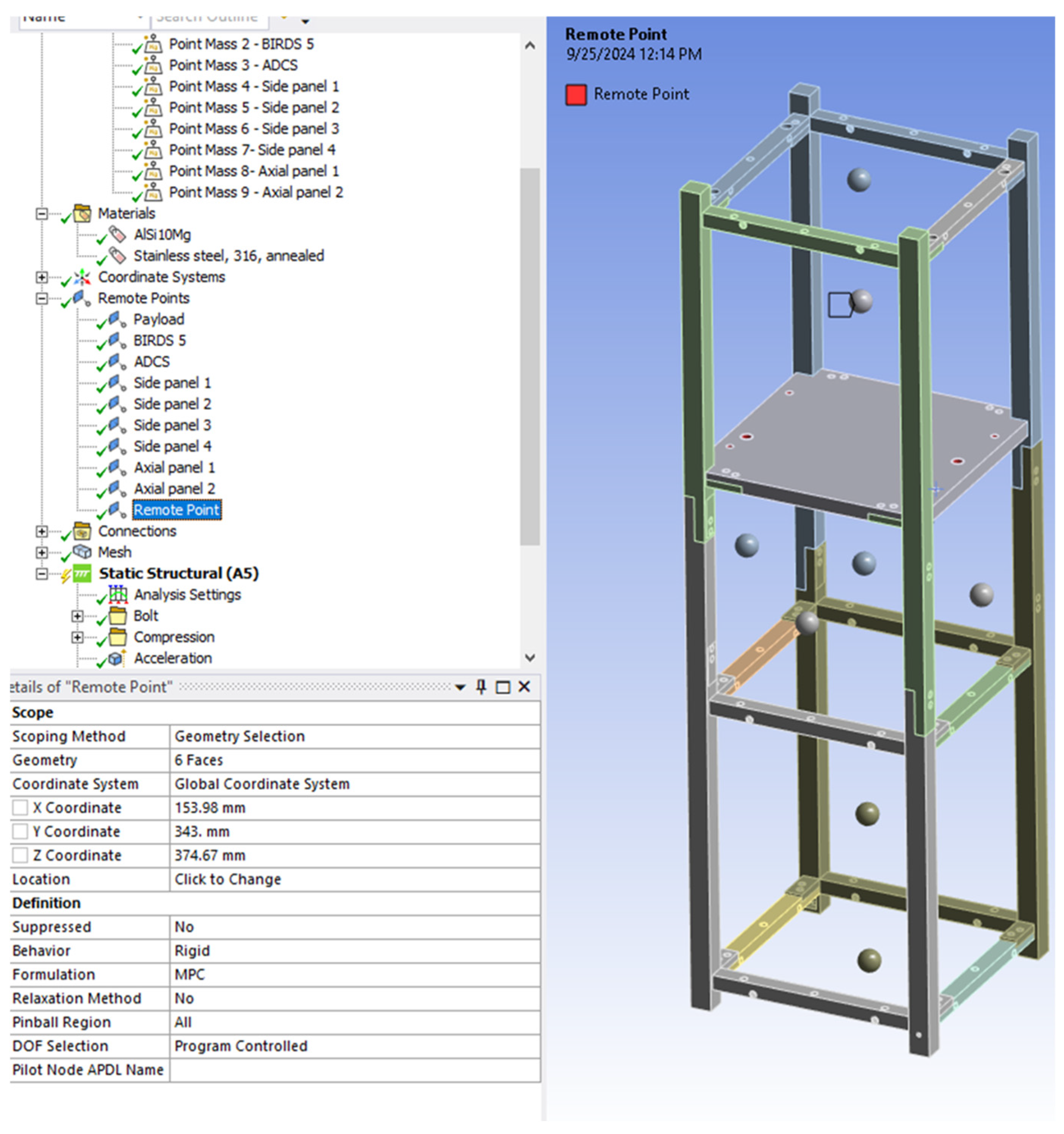
To accurately simulate the inertial effects of the satellite’s internal components without modeling their complex internal geometries, distributed masses were applied, as shown in Figure 3. Ten remote points were created to represent the following critical sub-systems:
Figure 3.
FEA model setup showing the distribution of remote mass points representing internal satellite sub-systems within the optimized frame.
- Primary Payload: The main imaging and data-gathering instruments.
- Secondary Payload: The Birds-5 data-gathering unit.
- AOCS: The Attitude and Orbit Control System mechanisms.
- Exterior Panels: The protective structures enclosing all six sides of the 3U volume.
With the mass distribution established, three distinct analyses were performed:
- Static Structural Analysis: Evaluated the maximum stress, strain, and deformation of the optimized frame under the peak 18.1 g acceleration load to verify that localized stresses did not exceed the material’s yield strength.
- Modal Analysis: Conducted to extract the fundamental natural frequencies and mode shapes. To accurately replicate the deployment case where the satellite is housed inside a deployment pod, boundary conditions were applied by fixing the −Z ends rigidly and applying a spring constraint at the +Z end. This analysis verified that the structure’s fundamental frequency exceeded the strict 30 Hz minimum stiffness requirement established by JAXA’s JEM Payload Accommodation Handbook—Vol. 8 [10].
2.3. Manufacturing and Post-Processing
The optimized frame was fabricated using an EOS M290 metal 3D printer with a layer height of 0.040 mm using infill settings with a laser power of 360 W, a laser speed of 720 mm/s and a hatch distance of 0.20 mm. These specific PBF-DMLS parameters dictate the melt pool dynamics, thermal gradients, and cooling rates, which inherently govern the microstructure formation and resultant density of the AlSi10Mg alloy. By tightly controlling these parameters, process-induced defects such as keyhole porosity and lack-of-fusion can be minimized. A critical research problem in metal AM is managing anisotropic mechanical properties, severe thermal distortion, and the trapping of loose powder inside complex internal lattices. To address these state-of-the-art challenges, the frame was strategically designed to be built in discrete segments oriented horizontally within the build chamber. Printing in this orientation minimizes the Z-axis build height, which significantly reduces the accumulation of thermal residual stresses and the risk of warping. Furthermore, these segments were printed with minimal necessary support structures and without fully enclosed void features. This ensures that any loose, unsintered powder can be easily accessed and extracted via vacuuming prior to assembly. Following the printing process, the part underwent a standardized stress-relief heat treatment cycle at 270 °C for 90 min as indicated in the Material Data Sheet (MDS) of the AlSi10Mg powder. This thermal profile was selected to relieve internal stresses formed during the rapid solidification process without inducing dimensional warping in the thin-walled organic features.
3. Results
3.1. Topology Optimization Results
The generative design process produced a topologically optimized 3U CubeSat frame with a final mass of 155 g. The baseline, standard machined 3U frame used for comparison has a mass of 333 g. This optimization resulted in a 53% reduction in structural mass, as summarized in Table 2.
Table 2.
Weight reduction for the topology optimized 3U CubeSat frame.
3.2. Simulation Results
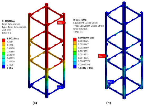
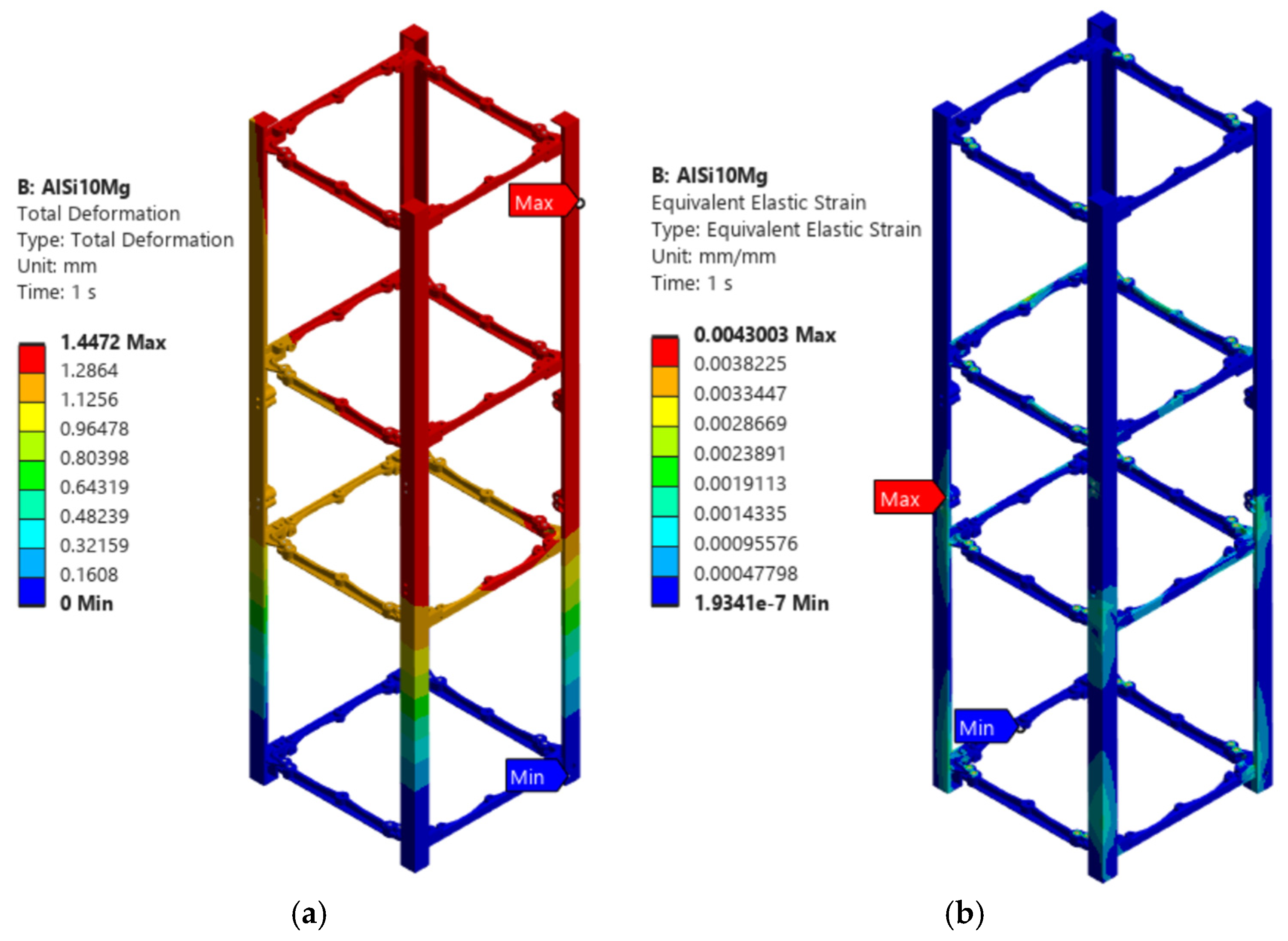
The optimized 3U CubeSat frame undergoes static analysis to determine the total deformation, equivalent elastic strain and stress. The total deformation is presented in Figure 4a where the maximum deformation reached 1.45 mm, observed at the upper section of the structure. Meanwhile, minimum displacement occurs at the constrained base regions. The smooth deformation gradient indicates a uniform load distribution without localized instabilities.
Figure 4.
Static analysis: (a) total deformation, (b) strain.
Figure 4b presents the equivalent elastic strain distribution, with peak values of approximately 0.0043 mm/mm concentrated at the strut junctions and connection interfaces. These regions correspond to the primary load-transfer paths within the topology-optimized structure. To assess the trade-offs of the AM approach, a direct simulation comparison was conducted against a conventional, non-optimized frame machined from 6061-T6 aluminum.
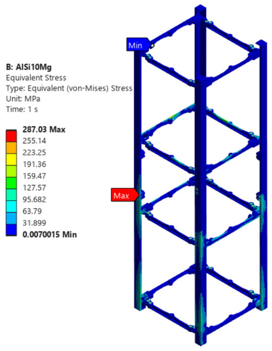
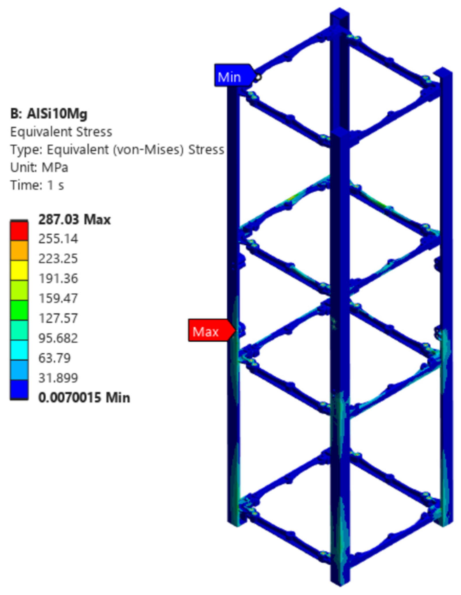
Figure 5 shows the expected quasi-static acceleration during launch; the maximum von Mises stress was 287 MPa, concentrated primarily at the lower mounting rails. Modal response analysis was also conducted.
Figure 5.
Von Mises stress results in MPa from static analysis.
Table 3 presents the comparison of the FEA results for the topology-optimized AlSi10Mg structure and conventional aluminum alloys (6061 and 7075). The results show that the AlSi10Mg model exhibits the lowest maximum von Mises stress (287.03 MPa) and strain (0.004), compared to 6061 and 7075 aluminum, which both reached stress values of approximately 506–507 MPa and strain values of 0.007. Additionally, the AlSi10Mg structure demonstrated slightly lower deformation (1.447 mm) relative to the conventional materials. These findings indicate that the optimized AlSi10Mg design provides more efficient load distribution and improved structural performance under the applied loading conditions. This improvement is attributed not only to the material but also to the benefits of topology optimization enabled by metal additive manufacturing.
Table 3.
Comparison of conventional aluminum (6061 and 7075) and AlSi10Mg.
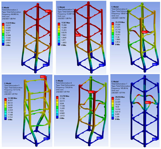
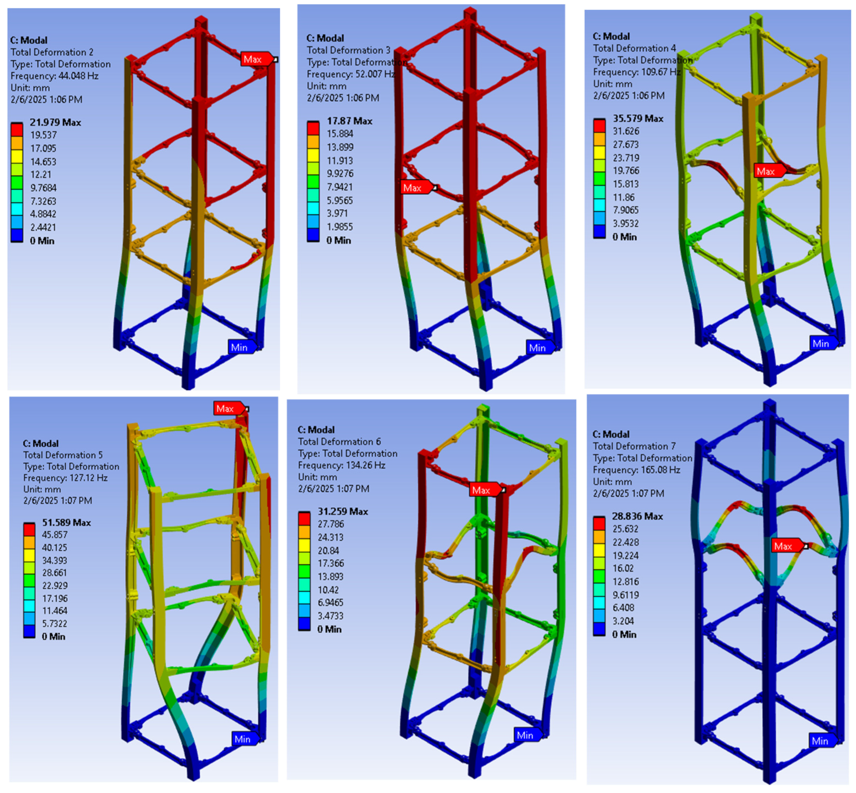
Figure 6 presents the first six mode shapes of the optimized 3U CubeSat frame, illustrating the structural response under dynamic conditions. Following the JEM payload accommodation handbook by JAXA [10], the boundary conditions are as follows. The acceleration was set at 1.531 × 105 mm/s2 while the −Z end of the 3U CubeSat frame was constrained. The fundamental modes (Modes 1 and 2) are characterized by global lateral oscillations, with maximum deformation observed at the upper sections while the base remains constrained. As the frequency increases, the mode shapes transition from global bending to more complex deformation patterns, including coupled bending and localized strut deformation in Mode 3. The simulation results are summarized in Table 4.
Figure 6.
Six (6) mode shapes ((left) to (right)) showcasing exaggerated oscillation and twisting at increasing frequencies.
Table 4.
Modal analysis of cube satellite frame.
3.3. Additive Manufacturing and Post-Processing
The optimized frame was successfully fabricated via Powder Bed Fusion—Direct Metal Laser Sintering (PBF-DMLS) using an EOS M290 system with AlSi10Mg powder. Following stress-relief heat treatment, CNC milling and surface grinding were performed on the critical mating rails, achieving a final surface roughness range of 0.1–0.5 µm on those specific interfaces.
3.4. Dimensional Verification Measurements
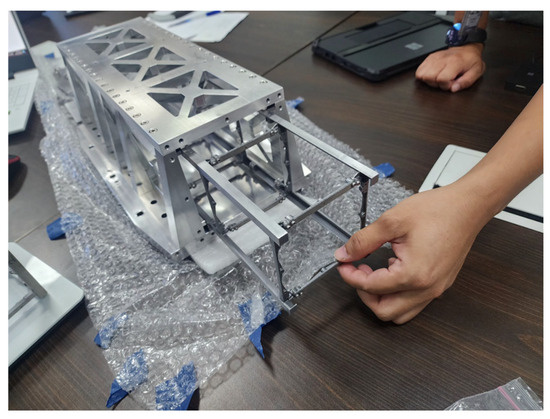
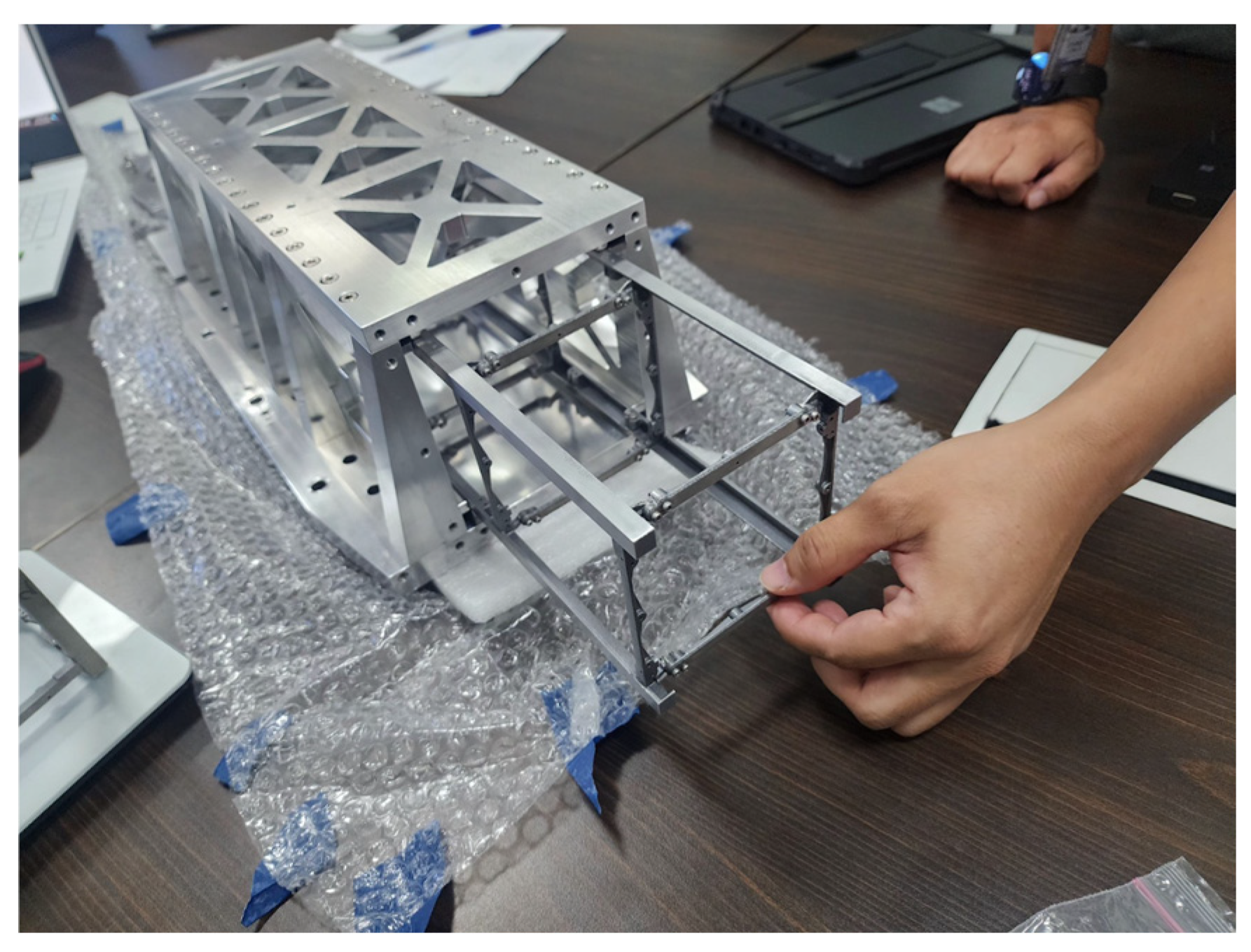
Dimensional inspection of the critical deployment rails was conducted post-machining, the results of which are summarized in Table 5. The rail widths and overall profile dimensions deviated by a maximum of 0.135 mm from the nominal design. Additionally, as a preliminary check of the post-processed rail surfaces, the 3U CubeSat frame was test-fitted inside a vibration test jig simulating the deployment pod, as shown in Figure 7. It is explicitly acknowledged that this geometric fit-check serves only to verify basic dimensional conformity and perpendicularity post-machining. It does not replace or satisfy JAXA’s stringent qualification requirements for deployment, which demand quantitative load-cell friction measurements.
Table 5.
Target vs. measured dimensions of critical deployment rail surfaces.
Figure 7.
Physical test-fitting of the optimized 3U frame on the launch test jig.
4. Discussion
4.1. Evaluation of Mass Reduction
The 53% mass reduction achieved through topology optimization demonstrates the significant advantage of utilizing additive manufacturing for space components. Traditional subtractive manufacturing methods cannot efficiently produce the complex, organic geometries generated by the optimization software. By removing material from low-stress regions, the structural efficiency of the frame is maximized, directly contributing to the goal of reducing launch payload costs without sacrificing mission capability.
4.2. Structural Integrity and Material Viability
Based on material characterization of the actual AlSi10Mg batch used, the alloy exhibited a yield strength of approximately 220 MPa. The FEA predicted a maximum von Mises stress of 287 MPa localized at the thinnest organic struts. Because this simulated stress exceeds the material’s yield limit, the current bare-frame design fails to maintain the strict elastic safety margin required for spaceflight hardware, posing a risk of localized plastic deformation. However, it is important to note that this simulation represents a conservative, worst-case scenario. In a fully integrated flight model, the primary frame is bolted to rigid external shear panels (e.g., solar arrays) and internal payload stacks. These integrated components provide significant structural reinforcement and load-sharing capacity. Therefore, while the current bare-frame results explicitly highlight the necessity for a subsequent design iteration to thicken high-stress nodes, future full-assembly simulations are required to determine the true extent to which panel integration mitigates these localized stresses.
4.3. Post-Processing and Interface Compliance
While additive manufacturing enables complex geometries, the as-printed surface finish of PBF-DMLS parts is generally incompatible with standard deployment mechanisms. JAXA’s Small Satellite Deployment Interface Control Document strictly requires a maximum surface roughness of 1.6 µm along the mating rails to prevent the satellite from jamming inside the deployer. It is important to note that surface roughness measurements and post-process machining were conducted in this study not to evaluate the general machinability of AM AlSi10Mg against wrought alloys, but strictly to verify that the printed part could be modified to comply with JAXA’s critical deployment interface requirements. The successful reduction in roughness to below 0.5 µm via CNC milling confirms that AM parts can be reliably finished to meet strict aerospace deployment tolerances. While the mating rails successfully met the ≤1.6 µm Ra standard, the unmachined organic struts retain the characteristic, rougher surface finish of AM components. This increased internal surface area must be evaluated in future work to understand its potential implications regarding outgassing and thermal emissivity in a vacuum environment.
A primary concern with DMLS is the potential for thermal distortion and warping during the printing process, which could render a CubeSat frame undeployable. The dimensional verification results demonstrate high physical fidelity, with all critical rail dimensions falling well within the required 0.1 mm tolerance band. The successful physical test-fitting optimized frame structure also ensures proper sliding during launch. These combined physical validations demonstrate the frame’s readiness for further qualification tests (such as physical vibration testing) and highlight the structural potential of metal AM in functional nanosatellite applications.
5. Conclusions
This study successfully demonstrated the viability of utilizing advanced metal additive manufacturing and topology optimization to redesign and fabricate a 3U nanosatellite frame. By transitioning from a standard machined wrought aluminum frame to a topologically optimized AlSi10Mg structure produced via PBF-DMLS, a substantial mass reduction of 53% (from 333 g to 155 g) was achieved.
Finite Element Analysis validated that the optimized organic geometry possesses the necessary structural integrity to withstand simulated launch conditions, exhibiting a maximum localized von Mises stress of 287 MPa—well within the material’s yield limits. Furthermore, modal analysis confirmed the frame’s dynamic stiffness. While the as-printed surface finish of the AlSi10Mg parts required post-processing, targeted CNC milling and surface grinding successfully brought the critical deployment rails into compliance with JAXA’s 1.6 µm maximum surface roughness and 0.1 mm dimensional tolerance requirements. Physical test-fitting of standard payload modules further confirmed the preservation of internal volume constraints. Ultimately, this methodology highlights the significant potential of additive manufacturing to reduce payload mass and launch costs for emerging space programs, providing a structurally sound and dimensionally compliant alternative to traditional subtractive manufacturing for small satellite structures.
Finally, it is explicitly acknowledged that the findings of this study are limited to computational simulations and preliminary manufacturability assessments of a bare-frame configuration. The current structural iteration serves as a conservative baseline where predicted localized yielding remains, leaving the core premise of the frame’s space-readiness unproven. Elevating this feasibility study into a flight-qualified architecture requires a phased approach for future work. First, full-assembly simulations must be conducted, integrating external shear panels and internal payloads, to determine the true extent of structural load-sharing and reinforcement. Subsequently, comprehensive flight qualification must transition to rigorous empirical validation, including quantitative load-cell deployment friction tests, physical random vibration and shock testing, empirical tensile characterization of the AM components, and thermal vacuum chamber (TVAC) evaluations to assess the outgassing and emissivity of the unmachined internal AM surfaces.
Author Contributions
Conceptualization, J.B.P.III, L.O.C., U.A., H.R., R.P., A.O.N., P.W.L. and R.W.; methodology, J.B.P.III, L.O.C., U.A., H.R., R.P., A.O.N., P.W.L. and R.W.; validation, L.O.C., J.B.P.III, U.A., R.P., A.O.N. and P.W.L.; formal analysis, J.B.P.III, L.O.C., U.A., R.P., P.W.L., A.O.N., R.W. and M.C.T.; investigation, J.B.P.III, L.O.C., U.A., R.P., P.W.L., A.O.N., R.W. and M.C.T.; resources, M.C.T.; data curation, J.B.P.III, L.O.C., U.A., H.R., R.P., A.O.N. and P.W.L.; writing—original draft preparation, J.B.P.III, L.O.C., U.A. and H.R.; writing—R.P., P.W.L., A.O.N., R.W. and M.C.T.; visualization, J.B.P.III and L.O.C.; supervision, U.A., J.B.P.III and M.C.T.; project administration, U.A., J.B.P.III, L.O.C. and H.R.; funding acquisition, U.A., J.B.P.III, L.O.C., H.R. and M.C.T. All authors have read and agreed to the published version of the manuscript.
Funding
This research was funded by the Philippine Government’s Department of Science and Technology, and monitored by the Philippine Council for Industry, Energy, and Emerging Technology Research and Development (PCIEERD) under the Grant-in-Aid Program “Central Hub for Additive Manufacturing in the Philippines (CHAMP Program)” under the Project “Technical Readiness and Innovation through Additive Manufacturing in the Philippines (TRIAMPH)” with DPMIS ID: 2022-03-A2-PCIEERD-2024-9758 and Entry Code: 11233.
Data Availability Statement
The raw data supporting the conclusions of this article will be made available by the authors on request.
Conflicts of Interest
The authors declare no conflict of interest.
Abbreviations
The following abbreviations are used in this manuscript:
| AM | Additive Manufacturing |
| AOCS | Attitude and Orbit Control System |
| CMM | Coordinate Measuring Machine |
| CNC | Computer Numerical Control |
| DMLS | Direct Metal Laser Sintering |
| FEA | Finite Element Analysis |
| FoS | Factor of Safety |
| JAXA | Japan Aerospace Exploration Agency |
| LEO | Low-Earth Orbit |
| PBF | Powder Bed Fusion |
| S&F | Store-and-Forward |
References
- Leccese, G.; Natalucci, S.; Fedele, A.; Cottini, V. Overview and Roadmap of Italian Space Agency Activities in the Micro- and Nano-Satellite Domain. In Proceedings of the 73rd International Astronautical Congress (IAC), Paris, France, 18 September 2022; pp. 18–22. [Google Scholar]
- Renga, A.; Gigantino, A.; Graziano, M.D.; Moccia, A.; Fedele, A.; Natalucci, S. Beamforming and Multi-Platform Image Synthesis for RODiO Distributed SAR. In Proceedings of the 73rd International Astronautical Congress (IAC), Paris, France, 18 September 2022; pp. 18–22. [Google Scholar]
- Sannino, A.; Mungiguerra, S.; Cassese, S.; Savino, R.; Fedele, A.; Natalucci, S. Fast reconfiguration maneuvers of a micro-satellite Constellation based on a hybrid rocket engine. In Proceedings of the 27th Congress of the Italian Association of Aeronautics and Astronautics (AIDAA 2023), Padua, Italy, 4–7 September 2023. [Google Scholar] [CrossRef] [Scilit]
- Kyushu Institute of Technology. BIRDS Bus Open Source. Available online: https://birds-project.com/open-source/ (accessed on 10 June 2026).
- Kim, S.; Maeda, G.; Cho, M. BIRDS Program Digital Textbook; Laboratory of Spacecraft Environment Interaction Engineering, Kyushu Institute of Technology: Kitakyushu, Japan, 2019. [Google Scholar]
- Heidt, H.; Puig-Suari, J.; Moore, A.; Nakasuka, S.; Twiggs, R. CubeSat: A new generation of picosatellite for education and industry low-cost space experimentation. In Proceedings of the 14th Annual AIAA/USU Conference on Small Satellites, Logan, UT, USA, 21–24 August 2000. [Google Scholar]
- Puig-Suari, J.; Turner, C.; Ahlgren, W. Development of the standard CubeSat deployer and a CubeSat class PicoSatellite. In Proceedings of the IEEE Aerospace Conference, Big Sky, MT, USA, 10–17 March 2001; IEEE: Piscataway, NJ, USA, 2001. [Google Scholar]
- Swartwout, M. The first one hundred CubeSats: A statistical look. J. Small Satell. 2013, 2, 213–233. [Google Scholar]
- NASA. CubeSat 101. Basic Concepts and Processes for First-Time CubeSat Developers. Available online: https://www.nasa.gov/wp-content/uploads/2017/03/nasa_csli_cubesat_101_508.pdf?emrc=05d3e2 (accessed on 10 June 2026).
- JAXA—Japan Aerospace Exploration Agency. JEM Payload Accommodation Handbook; JAXA: Chofu, Japan, 2023; Volume 8. [Google Scholar]
- Orme, M.; Madera, I.; Gschweitl, M.; Ferrari, M. Topology optimization for additive manufacturing as an enabler for light weight flight hardware. Designs 2018, 2, 51. [Google Scholar] [CrossRef] [Scilit]
- nTopology. Air Force Optimizes CubeSat Using Architected Materials. Available online: https://ntopology.com/case-studies/air-force-optimizes-cubesat-using-architected-materials/ (accessed on 18 August 2022).
- Tomsk Polytechnic University. Tomsk-TPU-120 CubeSat Deployed in Outer Space. 2017. Available online: https://tpu.ru (accessed on 18 August 2022).


Disclaimer/Publisher’s Note: The statements, opinions and data contained in all publications are solely those of the individual author(s) and contributor(s) and not of MDPI and/or the editor(s). MDPI and/or the editor(s) disclaim responsibility for any injury to people or property resulting from any ideas, methods, instructions or products referred to in the content. |
© 2026 by the authors. Licensee MDPI, Basel, Switzerland. This article is an open access article distributed under the terms and conditions of the Creative Commons Attribution (CC BY) license.