


Abstract
In the 21st century, the desire for improved fuel efficiency of engines, lower fuel prices, and the need to reduce greenhouse gas emissions such as and are leading the aviation industry to seek hybrid-electric jet engines for commercial aircraft. These aircraft will have greater maintenance challenges due to additional components requiring more reliable materials for the engine’s parts, such as turbine blades. Turbine blades must be composed of materials that have enhanced fatigue performance. Resistance to dynamic loads and high strength will be needed to ensure modern gas turbine blades are as reliable as possible. This review paper examines hybrid-electric engine turbine blades and subsequently introduces additive manufacturing (AM) and multi-principal element alloys (MPEAs) with a focus on laser powder bed fusion (LPBF), high-entropy alloys (HEAs), and medium-entropy alloys (MEAs). The tensile properties of LPBF HEAs range from 5 to 47% elongation and a UTS of 572–1640 MPa, while LPBF MEAs range from 8 to 73.9% and a UTS of 573–1382 MPa. This study focused on dynamic and fatigue properties while acknowledging gaps in high-temperature testing. The combination of mechanical properties with the ability to control internal geometry makes these AM alloys an attractive option for the next generation of gas turbine blades.
1. Introduction
Various international agencies, including the International Air Transport Association (IATA), are seeking reductions in emissions, while many airliners are looking to reduce fuel consumption [1]. Studies have shown that reducing the combustion temperature will lessen the emission of greenhouse gases such as and [2,3,4]. One major method for reducing emissions that has gained attention in aviation nowadays is the use of hybrid-electric engines. In a hybrid-electric engine, an electric motor can aid the internal combustion engine or gas turbine in generating thrust. This is especially useful when the aircraft is taxiing onto the runway or when climbing to the desired altitude [2]. There are three common configurations for hybrid-electric gas turbine engines: series, parallel, and a combination of the two systems. In a series configuration, the gas turbine propulsion is driven by the motor, while the internal combustion engine drives a generator that provides electrical power. The advantage of this system is that the motor can run at optimal settings while remaining independent of the powertrain; however, this system is less fuel efficient [4,5]. In a parallel configuration, the gas turbine and the motor are coupled with a planetary gear system, both working together to produce thrust, thereby saving on fuel consumption at the cost of complexity [4,5]. In the combined configuration of the gas turbine and motor, the engine drives the two turbines with the help of a motor [2,3,4,5]. Figure 1 displays an example of the configuration of a hybrid-electric gas turbine engine. Additionally, all-electric engines utilize only batteries to drive propulsion, whereas all-turboelectric and partially turbo electric engines use the rotational energy from the gas turbine to power the electrical systems for the aircraft, instead of just relying on a battery [1,2]. While the technology is still developing the incorporation of hybrid-electric systems to gas turbine engines is expected to reduce fuel cost across a fleet. It is for this reason that over the past thirty years the literature on this topic has grown.
Figure 1.
Parallel hybrid-electric gas turbine engines. Reproduced from [6].
Figure 2 shows the number of publications on hybrid-electric engines from 1995 to 2025 generated from the database Web of Science (WoS). The figure shows that for the past thirty years, nearly 15,000 publications have been produced, with a noticeable increase in the past decade, indicating greater interest in this technology by the academic and the industrial sectors. Among the studies of hybrid-electric engine systems in literature, the majority focus on power or control systems [1,2,3,4,5,6]. One overlooked aspect of this technology is the maintenance of hybrid-electric gas turbine engines. A study by Barke and coworkers found that by incorporating additional electronic components, the maintenance requirements for hybrid-electric engines will be greater than conventional gas turbine engines [4,7]. Given that the material properties needed for a hybrid-electric engine are the same as conventional aircraft, improvements on the design of these components and material selection may help save on maintenance costs [2].
Figure 2.
Hybrid-electric jet engine publications between 1995 and 2025 (WoS).
One of the most critical components of a gas turbine engine is the turbine blades, such as those identified in the bottom right of Figure 3. Gas turbine blades compress the air that enters the engine and moves it beyond the nozzle section to the combustion chamber and out the back of the engine, providing thrust [8,9]. As a result of the operational conditions, these components are subjected to thermal and centrifugal loads requiring materials with high strength and fatigue performance across a range of temperatures.
Figure 3.
Aero-engine components including turbine blades. Reproduced from [8].
Typically, turbine blades are fabricated from nickel superalloys due to their excellent mechanical properties in extreme environments [10]. Two new technological areas that are gaining interest are multi-principal element alloys (MPEAs) and additive manufacturing (AM). Multi-principal element alloys, sometimes referred to as either medium-entropy or high-entropy alloys, are alloys typically composed of equiatomic proportions of elemental metals. These alloys have shown excellent mechanical properties even at high temperatures due to the myriad of strengthening mechanisms available to them through their composition and microstructure. However, these materials are typically challenging to fabricate into complex geometries, and this is where additive manufacturing closes the gap [11,12,13,14,15,16,17]. Through additive manufacturing, low-weight parts may be fabricated while maintaining the tight tolerances needed for engine components. This is especially true of laser powder bed fusion which boasts fine equiaxed grain and initial dislocations which provide excellent strength while maintaining ductility [18,19]. Additively manufactured multi-principal element alloys have the potential for new blade designs that minimize weight through internal geometry while leveraging advantageous microstructural characteristics.
This article reviews the literature on AM MPEAs, with an emphasis on laser powder bed fusion (LPBF) AM technology; identifies material characteristics relevant for turbine blades; establishes mechanical properties of MPEAs fabricated by LPBF between 2020 and 2025; and concludes with suggestions for these materials, including an evaluation of LPBF MPEAs for turbine blade applications.
2. Multi-Principal Element Alloys and Other Alloys
At this point, it is important to make distinctions between multi-principal element alloys (MPEAs), also known as multi-principal component alloys (MPCAs), and complex concentrated alloys (CCAs). MPEAs are alloys in which three or more elements make up nearly equal proportions while maintaining integer proportions of the alloying elements. On the other hand, CCAs do not need to be of equimolar or integer proportions; they can have fractional or variable proportions of one or more of the alloying elements [13,14]. Historically, alloys have been composed of a single principal element with smaller amounts of other alloying elements that impart improvements in mechanical properties, microstructural features such as grain size, precipitation formation as well as other functional properties such as corrosion or oxidation resistance [13,14,15,16]. It was believed that the addition of nearly equivalent amounts of other elements would result in the formation of intermetallic phases within the microstructure, which would generate undesirable mechanical properties [14,16]. In a 1995 paper by Yeh, it was first proposed that the formation of a single-phase alloy with five or more elements of near-equal proportions would result in an increased configurational entropy and improved mechanical properties [16]. This concept has become known as high-entropy alloys (HEAs). This single stable phase had mechanical properties such as strength and ductility that made it a useful structural material [17,20,21]. These types of MPEA were designated as HEAs because the magnitude of the configurational entropy was greater than 1.5 times the ideal gas constant [13]. Figure 4 shows a Web of Science analysis of the number of publications over the past 30 years on MPEAs from 1995 to 2025. From the figure, over 5000 publications were observed in 2025 alone indicating growing interest in the scientific literature on these alloys.
Figure 4.
Publications on multi-principal element alloys from 1995 to 2025 (WoS).
The unique properties of high-entropy alloys identified by Yeh in 1995 are the following: high-entropy effect, lattice distortion, sluggish diffusion, and the cocktail effect. The high-entropy effect is explained by the increase in configurational entropy as the number of principal elements increases. Configurational entropy is defined as the entropy associated with the formation of the alloy [16]. Equation (1) shows the expression for obtaining the configurational entropy [22].
where R is the ideal gas constant, defined as 8.314 , and is the mole fraction of each of the elements that make up the alloy [22]. Due to the increase in configurational entropy, the enthalpy of formation has a less significant impact on the Gibbs Free Energy of the alloy [16]. Yeh observed that as the number of principal elements increased the configurational entropy increased nearly logarithmically [16]. Interestingly, when first studied, a single stable phase was found, which resulted in an alloy with excellent strength and ductility [14,16,20,21,23]. The lattice distortion effect is due to the increased number of elements that are formed within the alloy’s matrix [14]. Figure 5 presents a comparison between a conventional alloy and a HEA. In a conventional alloy, there is a single principal element, with one or more elements in solid solution within the metal’s matrix. However, for HEAs with nearly all the elements of equal proportion within the alloy, the elements are not dissolved but can be thought of as solutes themselves. This produces significant strain within the crystal lattices that make up the matrix of the HEA. These increases in strain along with the solid solution strengthening attributed to so many solutes within the alloy impede the motion of dislocations [12,24,25,26,27]. Dislocations are nanosized line defects that travel within the crystal lattice of an alloy that result in plastic deformation at macroscopic scale [24]. When the motion of dislocations is opposed, deformation is resisted, resulting in a stronger alloy.
Figure 5.
Crystal structures of a conventional alloy and a high-entropy alloy. Reproduced from [23].
2.1. Configurational Entropy as a Classification for Alloys
Yeh found that as the number of alloying elements increased, the peaks associated with the XRD (X-Ray Diffraction) pattern decreased, making them less visible to the background. This was due to the lattice distortions making it challenging for XRD patterns to distinguish between peaks [16]. Miracle and Senkov noted that to properly characterize crystallographic effects for HEAs and other MPEAs, it is important to use TEM (Transmission Electron Microscopy) in tandem with XRD [17]. Sluggish diffusion is another effect that is attributed to HEAs. It was once believed that the presence of so many alloying elements meant that the diffusion of elements through the matrix of a HEA was more tortuous than that of traditional alloys. Though other authors debated this conclusion, there was not enough evidence in the literature to confirm this claim [17]. The cocktail effect for high-entropy alloys refers to the phenomenon that indicates that the combination of large configurational entropy and the other effects from the contribution of alloying elements and principal elements would result in complex material properties with benefits beyond strength and ductility [21,22,23].
These characteristics have resulted in a surge of research in the field, especially within the past decade. As studies into HEAs continued, it was found that alloys needed to be distinguished among HEAs, MEAs, and low-entropy (conventional) alloys. Low entropy are alloys in which the configurational entropy is below 0.6 R, where R is the ideal gas constant [22,23]. Most low-entropy alloys have one principal element with smaller proportions of other alloying elements such as aluminum alloys, low alloy steels, or titanium alloys [21]. MEAs are the alloys which have a configurational entropy between 0.6 R and 1.5 R [15,21]. Alloys of these types have two or three elements that are in comparable proportions such as austenitic stainless steels or nickel superalloys. In fact, Miracle and colleagues found that 316 L SS has similar properties as many HEAs especially at elevated temperatures [17]. This potentially makes it a less expensive substitute for setting up parameters for high-temperature mechanical experiments of more expensive MEAs or HEAs [21]. Figure 6 depicts a scale distinguishing between low-entropy, medium-entropy, and high-entropy alloys, with high-entropy alloys identified. Configurational entropy increases from left to right; the gray arrow identifies the definition of high-entropy alloys.
Figure 6.
A scale for classifying alloys by their configurational entropy.
2.2. Common Strengthening Mechanisms for MPEAs
Both MEAs and HEAs use strengthening mechanisms common to conventional alloys driven by microstructural characteristics. These mechanisms include grain boundary strengthening, precipitation strengthening, twinning, and solid solution strengthening among others [25,28]. In grain boundary strengthening dislocations have difficulty crossing grain boundaries, because each grain within the microstructure is oriented randomly. Since grain boundaries are also amorphous, it is more challenging for dislocations to travel through them. This kind of strengthening is described by the Hall–Petch effect, in which to a certain extent the yield strength increases as grain size decreases [24]. Precipitation strengthening is attributed to the nucleation of nanosized particles that are coherent with the matrix of the alloy [15,24]. For dislocations to move through the matrix they must either shear these particles or, in some cases, overcome the strain field that is generated by their presence. Since these particles are evenly distributed, their effect is spread throughout the alloy providing consistent strengthening [29]. Certain elements increase the presence of precipitates, and the formation of precipitates is controlled by heat treatment designed to grow precipitates to an appropriate size [12]. Twining is what happens when dislocations are unable to slip due to the lack of shear stress, but the crystal deforms by shearing in a manner that divides it into two sections that are mirror images of each other. The mechanism allows for additional ductility along with strengthening, as the boundary between twins is difficult for dislocations to traverse due to the amorphous nature of the boundary [25]. Twining at the microscopic scale is known simply as twining, whereas twining at the nanoscale is known as nanotwinning [25]. Twining often accounts for the enhanced strength and ductility experienced by multi-principal element alloys at cryogenic temperatures [12,25]. One of the most common strengthening mechanisms in the literature for MPEAs is that of solid solution strengthening. Due to the alloy being composed of three or more elements that form a single phase, there is a significant amount of dislocation pinning that occurs. In solid solution strengthening, the elements in the solution can intercept the movement of dislocations due to the strain within the matrix. This pinning adds strength to the alloy and accounts for the high strength of many MPEAs [24,25]. Many HEAs are known to have excellent properties at high temperatures, including creep resistance and strength, which are beneficial for aerospace applications such as turbine blades. While Miracles and Senkov found that 70% of the studies on HEAs were conducted on as-cast materials, there is a potential for new research that can contribute to the development of new turbine blades, given the promise of additive manufacturing and its use in aerospace [8,14,17,20,23,25].
3. Additive Manufacturing Processes
Additive Manufacturing (AM) involves fabricating parts through stacking layers with heated feedstock material. The feedstock materials are often in either powder or wire that is heated and solidified or sintered in layers [27]. Depending on the process parameters, this provides varying microstructures that can be modified for greater control of the material properties of the components to be printed [27]. Unlike subtractive manufacturing processes such as machining or grinding, in which a raw material is converted into a product by material removal, additive manufacturing forms a near-net-shape product by adding layers until they form a three-dimensional shape [30]. Figure 7 shows the number of publications on additive manufacturing from 1995 to 2025, as available through Web of Science. Based on the current trends shown in Figure 7, it is expected that this field of research will continue to expand in the coming years. Additive manufacturing allows for greater control of the complex geometries, including the design of the internal structure of a component, which may lead to lighter and stronger turbine blades in the future [11]. For metal additive manufacturing, the main methods used are laser powder bed fusion (LPBF), electron beam powder bed fusion (EB-PBF), laser directed energy deposition (LDED), and wire arc additive manufacturing (WAAM) [11,31,32,33].
Figure 7.
Additive manufacturing publications from 1995 to 2025 (WoS).
3.1. Overview of Additive Manufacturing Processes
In LPBF, metal powder is used as the feedstock for the printer. A layer of metal powder is uniformly spread on a plate. Then, a laser beam rasters across the metal powder layer, melting or sintering the powder in the predefined pattern at a specified speed, laser power, and resolution. Once the laser beam completes the pattern, the beam is shut off, and a new layer of powder is spread over the previous solidified layer, and the process resumes. The thickness of these layers is specified, along with the other parameters for the process [11,30]. EB-PBF is a process similar to LPBF, except that it uses an electron beam rather than a laser. Due to the use of electron beams, EB-PBF requires a vacuum environment, yet it reduces contamination that would arise from an oxygen-rich environment [11]. One note is that the powders used in EB-PBF tend to be of a coarser size, so the resolution of this process is not as fine as with LPBF, resulting in rougher surface finishes and mechanical properties that are comparable to cast components. The main advantage of EB-PBF is shorter build times due to more power used when compared to LPBF, faster scan speeds of an electron beam, and the ability to build components from oxygen-sensitive alloys [11]. LDED is another common method for additive manufacturing, in which the feed material can be either powder or wire, and the feed material is inserted into the melt pool, which is generated through laser energy [33]. In LP-DED, melt powder is blown into the melt pool as a means of forming the next layers of the printed component. This process typically requires the atmosphere of the melt pool to be composed of an inert gas. In the case of laser wire DED (LW-DED), wire is fed into the melt pool and due to the use of wire and the amount of materials, the build speed is typically faster than either LPBF or EB-PBF. As a result, laser DED methods allow for the fabrication of larger components, at the cost of decreased resolution of the layers, resulting in rougher surfaces, which will require more extensive post-processing [11,33]. WAAM is a directed energy deposition method that is recently receiving more attention in the research literature [31,32]. In WAAM, a wire is fed into the melt pool to build up layers [11]. The technique bears similar characteristics to traditional welding and was once called 3D welding [32]. In this method, a plasma arc acts as the energy source that melts the feedstock wire as the deposition head moves in a pattern at certain speeds, with wire deposited at certain feeds for a given amount of plasma energy. Typically, the quantities from WAAM can be expected to be in the order of 30 g/min, which results in WAAM parts being built at speeds that far surpass those of other methods [11,30,32]. However, due to the as-built microstructure possessing grains that are typically of an acicular nature, additional heat treatments are needed to induce grain growth and create a more equiaxed grain structure. The mechanical properties of WAAM parts are typically similar to those of cast parts made from the same material.
3.2. Additively Manufactured Multi-Principal Element Alloys
In recent years, there has been growing interest in the scientific literature on additively manufactured multi-principal element alloys (AM MPEAs), which include multi-principal element and complex concentration alloys possessing configurational entropies of at least 0.6 R or higher. Figure 8 shows an analysis of open access publications between 2020 and 2025 that include the following additive manufacturing processes: EB-PBF, LPBF, laser DED, and WAAM. From Figure 8, only 13 publications focused on EB-PBF, which makes sense given the requirement for a vacuum environment and the reduction in resolution and rougher surface finish when compared to LPBF [11]. WAAM has only 21 publications that were related to additive manufacturing of multi principal element alloys. This smaller quantity makes sense given that WAAM is a newer technology. Parts made by WAAM are typically larger, with more anisotropic mechanical properties, requiring additional heat treatments [31,32,33]. Laser DED has faster build speeds while maintaining surface finishes closer to those of LPBF; as a result, 79 publications have been written [11,33]. A key take away is that LPBF is dominant in scientific literature, since it provides the greatest level of resolution and finest grain sizes of the four AM processes, resulting in 201 publications. Due to the frequency of LPBF MPEAs, this will be the focus of the rest of this review paper. An additional finding during this review is the order of magnitude of these papers in the literature on LPBF MPEAs, which ranges from dozens to a couple of hundred. This indicates that the field is not only growing but also open to many researchers. Figure 9 shows the number of open access publications for LPBF MPEAs from the top six authors between 2020 and 2025. Ren, Nakano, and Kim have the most publications, and these authors have h-indexes ranging from 15 to 88, indicating the wide range of impact of their publications in this research area. Even the most frequent author has only nine open access publications, indicating that this area of research is still understudied. Figure 10 presents the three journals with the most frequent open access publications in LPBF MPEAs between 2020 and 2025, namely Journal of Material Research and Technology, Materials and Design, and Additive Manufacturing, respectively. These journals are primarily focused on material science or additive manufacturing and not applications such as fatigue or plasticity. While the LPBF MPEAs are the most frequently published, it is clear that the focus of these alloys is still in fundamental material research spaces, and there is a need to move this research into specific applications, such as aerospace materials for gas turbine engine blades.
Figure 8.
Publications on EB-PBF, LDED, LPBF, and WAAM from 2020 to 2025 (WoS).
Figure 9.
Publications by the most frequent LPBF MPEA authors from 2020 to 2025 (WoS).
Figure 10.
Journals with publications on LPBF MPEAs from 2020 to 2025 (WoS).
3.3. Laser Powder Bed Fusion Parameters
LPBF dominates the literature due to the maturity of the technology and a refined grain size typical of the process, thus providing advantageous mechanical properties [18,27,34]. During the LPBF process, the metal powder is heated by a laser beam, sintering or by melting the material to a certain layer thickness. The atmosphere during the LPBF process is typically an inert gas, such as argon. The presence of the inert gas provides all three heat transfer mechanisms of conduction, convection, and radiation to contribute to the process with varying degrees of effectiveness. Once cooled, another layer of powdered metal is swept onto the solidified metal resting on the bed also known as the build plate. The build plate must be large enough to act as a thermal reservoir transmitting the heat from the part being built to itself with minimal changes in temperature. This results in effective temperature control during the additive manufacture of the component. Figure 11 shows a schematic of the LPBF additive manufacturing process [34]. Once the laser has strafed the metal powder according to a preset pattern of hatch spacing specified in the program and the layer solidifies, more powder is added and the process is repeated. The parameters controlled in this process are the hatching spacing, laser scan velocity, laser powder, and layer thickness. Equation (2) describes the volumetric energy density (VED) or energy added to the material by the laser, where represents the laser power in W, is the scanning speed in mm/s, is the hatch spacing in mm, and is the thickness in mm of each layer of the print [35].
Figure 11.
Schematic of the LPBF additive manufacturing process. Reproduced from [34].
Hatch spacing is the distance between the paths that the laser beam travels on the bed during the build process. The laser scan velocity is the speed at which the beam travels across the work piece during the build process. The laser power is the wattage that is applied to the beam. This parameter contributes to the energy used to heat the beam and influences the rate at which heat is transferred to the metal powder. The layer thickness is the thickness of each solidified region of the part during the build process [18,35]. Thicker layers result in slower heat transfer to the layers below while thinner layers have the opposite effect. The microstructure of the resulting part produced by LPBF is strongly influenced by each of the parameters, especially since each of these parameters can contribute to the presence of defects, the temperature of layers of the part during the build process, as well as the microstructure [18,34,36]. One of the main advantages of the LPBF process is its microstructure; specifically, grains can be made finer than traditional manufacturing processes such as forming or metal cutting. In addition, alloys such as nickel superalloys, including IN718, Hastelloy, or HAYNES 230, among others, can be more easily fabricated into complex geometries through LPBF than through other manufacturing processes [10,11,28,30,31,32,33,34,35,36,37,38].
3.4. Common Defects in Laser Powder Bed Fusion
In the LPBF process, the defects that are of major concern are lack of fusion, voids, un-melted particles, inclusions, and microcracks. These defects reduce the strength, ductility, and fatigue life of components. Lack of fusion occurs when insufficient energy is imparted between the layers resulting in voids and poor bonding between layers. Since LPBF occurs within an atmosphere of an inert gas it is possible for gases to be trapped within the part resulting in gas bubbles or voids once the metal has solidified [27]. Another defect that can occur is that of un-melted particles. This occurs when insufficient heat is conducted into the metal powder by the laser or between layers. When an un-melted particle is present within the metal, it can act as a crack initiation site or become more easily dislodged when loaded, resulting in a reduction in the strength or ductility of the metal [27,36]. Microcracks are also a common defect. These are often attributed to the tensile residual stresses generated as layers are heated resulting in a temperature gradient between the layers [39,40]. Metals in their powder form are less efficient in conducting thermal energy, thus further contributing to residual stresses [36]. The presence of these microcracks reduces the tensile strength as well as the fatigue performance of the AM metal. Inclusions from slag or oxide inclusions due to the melting of the metal powder when embedded in the metal tend to act as stress concentrators [27,39]. To remove these defects, it is necessary for the solidified product to undergo additional manufacturing processes known as post-processing, such as machining and heat treatments. It is estimated that approximately one-quarter of the final cost of is attributed to post-processing [36].
3.5. Heat Treatments
Heat treatments can modify the microstructure and internal defects of LPBF metal parts. The three main heat treatments that are common for post-processing LPBF products are solution/ageing, stress relieving and hot isostatic pressing (HIP) [36]. Solution/ageing refers to the process of solution annealing and ageing. In the case of solution annealing a metal is heated to a temperature that dissolves various dispersed phases within the structure. The alloy is then held at that temperature until only a single phase is present. The rate at which the metal is cooled controls the room temperature microstructure with faster cooling allowing for maintaining the grain size or microstructure and slower cooling allowing for grain growth [24]. Solution heat treatments are used for preparing the micro-structure for another process such as ageing. During an ageing heat treatment, the temperature is set to allow for the precipitation of nano-sized intermetallic compounds known as precipitates. These precipitates are coherent with the metal’s matrix, impede the motion of dislocations and thus add strength. They are thermally stable below the solution temperature, and in the case of alloys such as IN718, they add strength at elevated temperatures [41]. Another heat treatment that is important for post-processing AM parts is stress relieving heat treatments. LPBF is a layered manufacturing process and due to the decrease in the thermal conductivity of metal powders when compared to their bulk counterparts, thermal gradients within the AM metal result in tensile residual stresses [19,38]. These internal tensile residual stresses open up existing microcracks as well as distort the overall geometry of the part. Residual stress heat treatment is an annealing process that removes these internal stresses through the thermal annihilation of dislocations at elevated temperatures. This process may reduce the strength of the part and therefore reduce the fatigue performance [19,37,38,39]. Finally, the hot-isostatic pressing (HIP) process uses a pressurized inert gas to compress the part at elevated temperatures. This results in the closing of cracks and pores as well as the removal of lack of fusion and other defects associated with additive manufacturing [15,42,43]. An added benefit of HIP’ing is that the material will be at an elevated temperature for several hours depending on the specific process which can reduce residual stresses. HIP’d parts essentially experience the removal of defects while undergoing a heat treatment that may, under the right conditions, convert the as-built grain structure to a more equiaxed grain structure [37]. Figure 12 shows a schematic of the HIP process that follows LPBF. Each of these heat treatments are used to remove internal defects or control the microstructure of the metal itself, however, they have little to no effect on the presence of external defects [11,18,31,32,33,34,35,36,37].
Figure 12.
Schematic of hot isostatic pressing (HIP) after LPBF. Reproduced from [43].
3.6. Common Post-Processing Methods
Since AM can produce near net shape parts one of the most common post-processing methods is machining. During machining, a tool is used to remove the excess material to bring a part to its final shape. Machining processes such as turning can reduce the roughness of a part. The presence of features with sharp microscopic corners such as notches act as stress raisers and crack imitation sites. The turning process removes these features leaving a smaller surface finish than the as-built condition. Grinding and polishing are used to remove minuscule quantities of excess material and relieve stress. Grinding is a cutting process that removes smaller volumes of material than machining. Polishing is a process that removes an even smaller number of material than grinding but reduces the surface residual stresses. The process of polishing minimizes the surface finish or roughness and by doing so removes possible crack initiation sites, significantly improving the fatigue life of the part. Another means of improving fatigue life is to apply compressive residual stresses two common methods are shot peening and laser shock peening [44,45]. In the case of shot peening the surface of the additively manufactured alloy is impacted by small spherical projectiles resulting in a compressive residual stress within the metal. This residual stress ensures that for cracks to initiate the tensile stress must overcome the compressive residual stress as well as be sufficient to further open the crack [39,44]. In 2021, Musekamp and colleagues conducted a study on Scalmalloy produced via laser powder bed fusion and they found that the fatigue limit of the LPBF specimen was twice that of the as-built specimen [39]. In laser shock peening, a part is covered in an absorbent material and submerged in deionized water. A pulsed laser beam impacts the absorbent material creating a shock wave that imparts a compressive residual stress on the part. This residual stress makes it more difficult for tensile stresses to open a crack, thus improving the fatigue performance. Since laser pulses have pulse widths between 10 and 15 nanoseconds, there is no heat-affected zone. While internal defects influence tensile strength and fatigue performance, the surface finishes and residual stresses have a more pronounced effect on fatigue life [39,40,44].
4. Turbine Blade Materials
Traditionally, nickel superalloys have been used in the fabrication of components for gas turbine engines [10,38,46]. Gas turbine blades for conventional and hybrid-electric engines require outstanding fatigue, creep, and tensile properties across temperature ranges, high corrosion resistance, and excellent toughness when impacted with foreign objects such as birds or dislodged components of the engine itself [45,46]. Nickel superalloys such as IN718 boast tensile strengths at ambient and 650 °C in the range of 720 MPa to 780 MPa, respectively [10]. In addition, IN718 can be made as a single crystal to ensure there is more resistance to the movement of dislocations at elevated temperatures; thus, increasing the fatigue performance of IN718. In addition to good creep performance, IN718 also has good fatigue performance at room temperature. Benedetti and colleagues obtained a fatigue life of 3 × cycles for an AM specimen [10,19,38]. IN718 is also resistant to erosion. Other alloys with high wear resistance are used for gas turbine blades including IN738. This material is known for its excellent mechanical properties at elevated temperatures [10,38]. Nickel superalloys have been used since the mid-twentieth century for aerospace applications. The blades are often cast as single crystals to ensure enhanced creep performance. Since creeps usually initiate at grain boundaries the use of single crystals mitigates this phenomenon because it has no grain boundaries [10,38]. While nickel superalloys perform very well at both room and high-temperature environments, their application in hybrid-electric jet engines will generally focus on temperatures lower than what is required to initiate creep. The mechanical properties of nickel superalloys are critical for their use in gas turbine engines, but the corrosion properties are also important. The precipitates of IN718 impeded the formation of pitting corrosion within the blade [46,47,48]. While corrosion is known to adversely affect the fatigue performance of nickel superalloys, Gabb and colleagues found that IN718 had a reduction in fatigue life by two to three orders of magnitude after experiencing varying degrees of corrosion [48].
5. Failure Modes of Turbine Blades
Whether operating traditional aircraft or hybrid-electric aircraft, gas turbines require materials that are resistant to the failure modes common to gas turbine blades. Figure 13 shows the number of publications from 1995 to 2025 on failure modes that are common to gas turbines. These failure modes include distortion of the blade due to residual stress, erosion, corrosion, hot corrosion, fatigue, creep, impacts from debris, and fouling [46,47,48,49,50,51,52]. While impact or foreign object damage is one to two orders of magnitude greater than the other failure modes, high-temperature fatigue is noted as the least studied and represents a significant gap in the literature, with only 69 publications found in the open literature on WoS between 1995 and 2025.
Figure 13.
Publications about common gas turbine failure modes (obtained from WoS).
Due to the centrifugal forces associated with rotating turbines, more than 10,000 RPMs [52,53], as well as the extreme environment associated with combustion within the engine, residual stresses may build up within individual turbine blades that can lead to turbine blade distortion. When blade distortion arises in the material, the turbine blade may not be able to properly act as an airfoil and efficiently transfer momentum from the inlet to the outlet [52]. In addition, the air-to-fuel ratio can become too high, resulting in increased temperatures, which will deteriorate the engine through higher-than-normal temperatures [52]. Another challenge is due to particulates eroding the turbine blade. Erosion is the process by which small particles, or the fluid itself, remove material from the blades [49,51]. Typically, this process occurs when small particles such as combustion byproducts, or particulates from the engine, or microscopic particles from the outside are carried by the air and contact the blades. The amount of wear from this process depends on the prior condition of the blades, the environment, and the size of the particles [50]. Excessive erosion can wear the blades to a degree that they are unable to act as air foils according to their intended design. Yet another source of degradation for aircraft gas turbine engines is fouling. Fouling occurs when the particles on the order of 2 μm are carried into the gas turbine engine and adhere to the blades. These particles may be due to combustion byproducts, contaminants from the air or debris from within the engine [7,50,51,52]. Regardless, the effect of the adherence of these particles increases the nominal surface roughness of the turbine blades [7,54]. The increase in surface roughness impedes the blade’s ability to act as an airfoil that allows for sufficient air to enter the combustion chamber. This increases the fuel-to-air ratio, resulting in higher combustions temperatures, which immediately increase emissions and eventually reduce the life of the engine [7]. To prevent fouling, regular inspections and maintenance of the engines are performed to remove such particles according to a manufacturer-recommended maintenance schedule [50,51].
Particles can have a significant impact on the health of the engine. Moreover, the performance of the turbine blades can be compromised by the impact of larger projectiles, which can have catastrophic effects on the aero engines. Impact with a large body can damage the turbine blades due to high impact momentum resulting in plastic deformation [47]. For gas turbine engines within aircraft, one of the most common impacts is that of birds being sucked into the engine itself. When bird impacts are considered, the general understanding is that birds are assumed to have the density of water, and this is considered for impact testing. As a result, engines are tested extensively. While there is a need to further develop these tests to account for the different birds an aircraft may encounter, this will require blades that have sufficient strength and toughness to withstand impacts [47]. Particles and foreign objects are not the only factors that need to be considered in the design of blades for gas turbine engines. The rotation of the blades produces cyclic tensile stresses within the blade material; these stresses are known to result in fatigue failure over the life of the blade. Fatigue accounts for a significant fraction of failures in various industrial applications [47,51]. In the aircraft industry fatigue-based failures are common and is the reason for regular scheduling of maintenance on aircraft engines. Therefore, the blades must be composed of materials that have a fatigue limit at both room temperature and the elevated temperatures that are suitable for the life of the engine.
Figure 14 is a representative image of a gas turbine blade damaged during service, highlighting the need for materials with high strength and elastic moduli sufficient to maintain their geometry during loading at different temperatures, as well as sufficient fracture toughness to withstand the presence of cracks and mitigate catastrophic failures due to crack nucleation or propagation [55]. At elevated temperatures, another mechanical property that needs to be considered is creep. While for hybrid-electric engines temperatures are lower than those in conventional gas turbine engines, which can be kept low to reduces emissions, it is possible for conditions to occur, such as fouling, that can cause the blades to inefficiently move air into the engine, which can result in elevated temperatures [51,55]. Having materials that can maintain their geometry at elevated temperatures increases the life of components and reduces the maintenance needed for the engine. Creep is the process by which, at elevated temperatures, an alloy experiences plastic deformation at stresses that are below the yield strength. The strain rate is also small enough that the process will occur over long periods of time [55]. Creep is a problem for gas turbine blades because the elongation of the blades can result in the blades being incapable of acting as an efficient airfoil and in the worst case contact the interior of the engine resulting in catastrophic damage and failure. Therefore, the material used for these blades must also have sufficient creep resistance [56]. The last series of failure modes associated with gas turbine engines are the corrosion of the components.
Figure 14.
Common hot section defects for gas turbine blades. Reproduced from [56].
For gas turbine engines, there are two broad types of corrosion: corrosion and hot corrosion. In corrosion, an electrochemical reaction occurs in which the components of the engine oxidize. This can occur when the components are in contact with air that has a high salt concentration, such as near seawater [49,55]. Hot corrosion is an amplified corrosion that occurs when the air is at elevated temperatures, such as in the hot section of the engine, and the combustion products containing sulfides and other chemical compounds react with the surface [49]. The high temperature accelerates the corrosion process, and this can be especially dangerous [49]. In addition, the corrosion process increases the roughness of the surface due to the formation of pits. This has the adverse effects of creating more stress concentrations on the surface, leading to increased propensity for fatigue failure. With the presence of these corrosion products, the fatigue life of the turbine blade can be expected to decrease from its room temperature value [46,48,49,50,51].
6. Mechanical Properties of LPBF MPEAs
By combining the mechanical properties of MPEAs with the design freedom of AM, there is a potential for improving the life of aeroengine combustor components notably the turbine blades [18,53,57]. The rotation of the blades requires materials that can maintain excellent tensile strength, impact resistance, and fatigue performance. Figure 15 shows the number of open-source research publications on tensile and fatigue properties of LPBF HEAs between 2020 and 2025, obtained from the Web of Science database. Properties such as ductility, tensile strength, and yield strength are the most common mechanical properties across temperatures studied. These monotonic properties are among the most common collected for AM MPEAs since tensile tests are among the simplest to perform [13,36,43,58]. From Figure 15, the tensile properties of these alloys are better studied, given that ten times as many articles were published between 2020 and 2025 on this topic. While most tests were conducted at ambient temperature, three high-temperature studies on CrMnFeCoNi alloy, GRX-810, and Ni-Fe-Cr-Al-V alloy at elevated temperatures ranging from 200 °C to 1093 °C indicate the potential high-temperature performance of medium- and high-entropy alloys [42,59,60,61].
Figure 15.
LPBF MPEA mechanical testing publications from 2020 to 2025 (WoS).
6.1. Tensile Properties of LPBF MPEAs
Table 1 and Table 2 summarize the ambient tensile properties, strengthening mechanisms, and characterization methods from publications on LPBF HEAs from 2020 to 2025. The percentage elongation, yield strength (YS), and the ultimate tensile strength (UTS) are listed along with various strengthening mechanisms present due to the alloy’s microstructure. The strengthening mechanisms identified are dispersion strengthening (DS), grain-boundary strengthening (GB), phase-fraction or phase-boundary strengthening (PH), precipitation strengthening (PR), strain hardening (SH), and solid-solution strengthening (SS). The three most common strengthening mechanisms were GB, SH, and SS. The Hall–Petch effect is a well-established phenomenon, and the rapid solidification process in LPBF generates dislocation cells, which enhance strain hardening. A wide range of characterization techniques are used for identifying different microstructural features to explain the performance of these alloys. The least common methods are Atomic Probe Microscopy (APB), Differential Scanning Calorimetry (DSC), Optical Microscopy (OM), and X-Ray Photo Spectroscopy (XPS). The most common methods are EBSD (Electron Backscatter Detection), EDS (Energy Dispersive Spectroscopy), SEM Frac. (Scanning Electron Microscopy Fractography), TEM (Transmission Electron Microscopy), and XRD (X-Ray Diffraction). This makes sense given their use in analyzing grain structure, chemical analysis, imaging fractured surfaces, analyzing dislocation and nano-sized particles, and detecting secondary phases, respectively. In the case of tensile, fatigue or impact testing of a LPBF HEA, these methods are critical for understanding the microstructural and crystallographic origins of the material’s performance.
Table 1.
Summary of tensile properties, strengthening mechanisms, and findings on LPBF HEAs (2020–2025).
From Table 1, the most common material condition and temperature were as-built and ambient, respectively. This indicates that in most cases the alloys were tested with the microstructure corresponding to the post-print process at room temperature. This is to be expected, since it is first necessary to establish a baseline of the microstructure and mechanical properties of the alloy before conducting post-processing or high-temperature tests. Of the alloy groups identified, half are either the CrMnFeCoNi alloy or its derivatives, demonstrating the dominance of this alloy class in the literature [59,63,66,67,68,77,78]. For the AM HEAs at the ambient temperature, the percentage elongation, YS, and UTS have ranges of 5–47%, 480–1420 MPa, 572–1640 MPa, respectively. From these results, it can be said that AM HEAs have a low to moderate ductility while possessing high strengths ranging from 0.5 GPa to over 1.6 GPa. These properties are associated with their microstructure, which afford various strengthening mechanisms, with GB, SS, SH DS, and PR being the most common strengthening mechanisms and PH being the least common given that it corresponds to strengthening from interactions with different phases. Heat treatments are among the most common post-processing methods, with annealing and HIP being mentioned explicitly. A key finding is the lack of high-temperature studies conducted, most likely due to the challenges of testing at those temperatures. In general, LPBF HEAs possess excellent strength, with poor to moderate ductility.
Table 2.
Summary of tensile properties, strengthening mechanisms, and findings of LPBF MEAs (2020–2025).
Table 2 summarizes the tensile properties, strengthening mechanisms, and characterization methods from publications on LPBF MEAs from 2020 to 2025. Similarly to Table 1, the most common material condition and temperature were as-built and ambient, respectively. Among the medium-entropy alloys, the CoCrNi alloys are the most commonly studied, only two alloys in Table 2 are not derived from this composition [80,81]. At ambient temperature, the AM MEAs percentage elongation, YS, and UTS have ranges of 8–73.9%, 480–1420 MPa, and 573–1382 MPa, respectively. There are more heat treatments studies for LPBF MEAs than for LPBF HEAs, occurring in nearly a third of the studies. Similar to Table 1, very limited high-temperature tests have been conducted for these materials; thus, it is a research gap. In terms of strengthening mechanisms, while GB, SS, SH, and PR are dominant in the literature, DS appears once, while PH occurs twice.
Figure 16 displays the room temperature UTS vs. elongation as a scatter plot of LPBF HEA (indicated by circles) and LPBEA MEA (indicated by triangles) alloys. From Table 1 and Table 2, in general, LPBF HEAs are stronger than LPBF MEAs at the expense of elongation, while LPBF MEAs that have lower strengths generally have greater ductility. For table entries with multiple parameter settings, the optimal alloy based on a balance of strength and ductility is shown in the graph. Since the feedstock is a powder, it is possible to mix stronger phases into the metal powder, which will be dispersed through the alloy upon solidification; this is known as dispersion strengthening. These mechanisms appeared in six different studies shown in Table 1, while only one appeared in Table 2 for the alloy GRX-810 with the dispersed phases attributed to oxides, larger precipitate, and metallic glasses. In each case, the dispersed phases impede dislocation by deflecting dislocations around these harder objects [42,73].
Precipitation strengthening was also common, and these nano-sized intermetallic phases required dislocations to shear them. The least common strengthening mechanism of the LPBF MPEAs was phase strengthening, with only two papers mentioning this mechanisms, which adds strength through the presence of a phase with a different crystal structure that increases with phase fraction. A study by Yang et al. found that changing the parameters such as scanning speed the phase fraction of BCC phase could be controlled within the FCC medium-entropy alloy enhancing the strength while the TWIP (twining induced plasticity) effect provided additional ductility [80]. Li and colleagues studied an alloy which developed HCP phase with the FCC phase, with dislocations struggling to move within in the HCP phase due to fewer slip systems, thereby adding strength dependent on the phase fraction [75]. From Table 1, excluding cryogenic temperatures, seven of the 18 alloys listed in the table possess UTS exceeding 1 GPa, each of them due to a variety of strengthening mechanisms, indicating that these alloys can utilize varying strengthening mechanisms across temperatures. Evaluating Table 1 and Table 2 in general, the LPBF high-entropy alloys possess UTS ranging from 572 MPa to 1640 MPa and elongations ranging from 5% to 47%. The LPBF medium-entropy alloys, being mostly composed of CoCrNi alloys, have ultimate tensile strengths from 573 MPa to 1382 MPa, with elongations ranging from 8% to 73.9%.
As discussed in Table 1 and Table 2, a wide range of characterization techniques are used as the necessary method for identifying different microstructural features to explain the performance of these alloys. The most common are EBSD (Electron Backscatter Detection), EDS (Energy Dispersive Spectroscopy), SEM Frac. (Scanning Electron Microscopy Fractography), TEM (Transmission Electron Microscopy), and XRD (X-Ray Diffraction). In the case of tensile or fatigue testing of an LPBF HEA, these methods are critical for understanding the microstructural and crystallographic origins of the material’s performance. The least common methods were Atomic Probe Microscopy (APB), Differential Scanning Calorimetry (DSC), Optical Microscopy (OM), and X-Ray Photo Spectroscopy (XPS). The strengthening mechanisms and characterization techniques used correspond to the various microstructures available to LPBF MPEAs. Due to the powdered nature of the feedstock, it is possible to incorporate hard phases such as oxides or metallic glasses into these alloys. In addition, heat treatments such as HIP or ageing can minimize defects and growing nanoparticles within the alloys matrix to provide additional strength [42,61,64,70,73,79]. While grain boundary strengthening, solid solution strengthening and strain hardening are among the most common, using different powders or compositions can allow for the presence of other phases such as BCC or HCP phase in volume fractions to add strength with minimal reduction in ductility [75,80]. Overall, LPBF MPEAs have potential for various methods of microstructural design due to their powdered feedstock and heat treatability [14,37,64,73].
6.2. Fatigue and Dynamic Properties of LPBF MPEAs
The number of open-source publications on fatigue found on Web of Science between 2020 and 2025 is only two. Both publications show that tests were done at room temperatures. In the first article, Chen, Li, and colleagues tested a CoCrFeNi LPBF HEA, a CoCrFeMnNi alloy derivative, with a stress ratio of R = 0.1, which had a fatigue limit of 150 MPa corresponding to cycles [19]. The as-built performance was attributed to strengthening from the fine grain boundary and the dislocations cells derived from the rapid solidification of the AM process, contributing to strain hardening [18,19]. The second article was a 2024 study by Huang et al., who investigated the presence of nanotwinning on the tensile, fatigue and dynamic behavior of a CoCrFeNi high-entropy alloy. Similar to other low-stacking-fault-energy multi-principal element alloys, CoCrFeNi experienced twinning-induced plasticity, with additional twining at the nanoscale [86]. Their study concluded that the presence of the twin boundaries and the reduced grain size from the AM process sufficiently impeded dislocations, resulting in a fatigue life of cycles. The dynamic Hall–Petch effects contribution from twining resulted in an increase in strength while allowing for enhanced ductility [15,86].
In addition to possessing high strength during operation, it is critical for gas turbine blades to be resistant to impact loading [87]. Such blades can be expected to encounter bird strikes during operation and other forms of foreign object damage [51,54,87]. A common method for obtaining data on the dynamic behavior of materials is the Split Hopkinson Pressure Bar test (SHPB). In this experiment, a striker bar, incident bar, and transmitted bar are used to compress a sample at high strain rates [88,89]. A specimen is positioned between the incident and transmitted bars. Upon impact with the striker bar, the incident bar transmits a stress wave that dynamically compresses the sample. This stress wave propagates to the transmitted bar, which impacts a stopper [89,90,91].
Within the open literature of dynamic behavior of additively manufactured high-entropy alloys, the CoCrFeMnNi high-entropy alloy is the most common, and very limited work has been done in the area of high-strain-rate behavior of medium-entropy alloy. In a 2022 publication by Chen et al., CoCrFeMnNi alloy material was impacted at a strain rate of 3000 at 77 K, 173 K, 298 K, 673 K and 1073 K [90]. The results showed a decrease in dynamic yield strength from 665 MPa at 77 K to 450 MPa at 1073 K [90]. This study found that across the temperatures investigated, deformation twins interacted with dislocation pile ups at the twin boundaries. Moreover, the higher fraction of twin boundaries across the grains resulted in higher strength and ductility. The lower temperatures decrease the stacking fault energy, thus increasing the propensity for twinning. This explains the higher strength and ductility for 77 K through 298 K as compared to elevated temperatures of 673 K and 1073 K which is expected from FCC HEAs alloys [90,92]. An additional study of dynamic behavior by Du et al. [92], compared an as-built FeCoCrNi HEA to its as-cast counter part of the same alloy at strain rates of 1000 , 3000 , 5000 , and 10,000 . The study found that as the strain rate increased, both the strength and ductility increased for both the as-built and as-cast specimens. It is noted that for both material conditions, the ductility at a strain rate of 5000 was greater than the 10,000 while remaining at a lower strength, implying that the mechanisms is inherent to the alloy and not the processing method [92]. The microstructural features that were dominant in this study were grain boundary, microbands and deformation twins. The increase in strength was due to the presence of the barriers trapping dislocation which resulted in an increase in both strength and ductility [90,92]. The work hardening rate was greater for the as-printed specimens than the as-cast specimen due to the increased presence of dislocations due to the 3D printing process [18]. In both studies, the presence of twining and grains boundaries enhanced strength and deformation during dynamic loading [90,92]. Table 3 summarizes the key findings on the mechanical properties of these alloys. Overall, these materials have potential to withstand the fatigue and dynamic loads associated with the operation of gas turbines and foreign object damage that may occur during the life of an engine.
Table 3.
Summary of key findings for LPBF MEAs/HEAs.
7. Future Directions for LPBF MPEA Turbine Blades
7.1. Mechanical Testing of MPEAs
The advantages of using LPBF MPEAs are their outstanding tensile strength and fatigue performance, which are comparable, or in some cases superior, to those of nickel superalloys that are traditionally used in the field. The LPBF process provides fine grain sizes, as well as dislocation cell structures that enhance the strength and increase the fatigue life of the material under service loading conditions [19,60,77]. The use of powder allows for the addition of oxides or metallic glasses to the powder, thus enabling dispersion strengthening, which is known to add strength at elevated temperatures [42,58,72]. Additive manufacturing allows for the creation of components with more sophisticated geometries, including those that can result in using less material than a blade from conventional manufacturing processes. While these characteristics are beneficial, there is a need for gigacycle fatigue testing at cycles, as this better reflects the fatigue life requirements needed for a gas turbine engine [93]. Additionally, given the location of turbine blades, they would also need to be tested at temperatures such as those within an engine. High-strain-rate testing of MPEAs shows resistance to the impact of foreign objects; however, these tests need to be conducted at elevated temperatures as well, to challenge these alloys against the dynamic loads they may experience within the hot section of an engine.
7.2. Simulation of Gas Turbine Blade Materials
A comparison of LPBF MPEAs with nickel superalloys fabricated conventionally or through other additive manufacturing methods could be beneficial in understanding the influence of blade geometry and mechanical properties at different temperatures on the effectiveness of different gas turbine blade designs. In 2021, Kukla et al. performed an experiment in which they took actual gas turbine blades, composed of an unspecified nickel superalloy, and cyclically applied bending loads at 950 °C while documenting the mechanical properties [94]. The team was successfully able to evaluate high stress regions through a simulation of the blades using a commercial finite element software [94]. The use of simulation to examine additively manufactured gas turbine blades can be used as a material selection strategy since the loads, thermal stresses and life of components may be estimated. Incorporating data such as that presented in Figure 16, in addition to data from fatigue and dynamic experiments, will allow for the screening of materials for potential uses in gas turbine engines [94,95,96,97,98,99,100]. These studies demonstrate the possibility of using mechanical testing to obtain material data for evaluating different designs under simulated conditions. Additionally, a comparison of ceramic materials is warranted, as ceramic matrix composites (CMCs) are an attractive alternative to superalloys used in the hot section of gas turbine engines. CMCs have lower weights, can withstand higher temperatures, and have excellent fatigue resistance, since part of the loading is based on the weight of the blades; however, they are less resistant to impact loading [99,100]. For LPBF MPEAs to remain competitive and be selected for gas turbine materials, their mechanical properties need to be compared with nickel superalloys and CMCs. Simulation methods can be used to virtually evaluate them and specifically identify competitive alloys for this design space [94,95,96,97,98,99,100].
7.3. Design of Gas Turbine Blades
A major advantage of LPBF is its ability to develop complex designs, including the internal features of a part. Earlier, CMCs were mentioned as being less dense than traditional superalloys and as competitors to LPBF MPEAs. While the density of a bulk component cannot be changed, the internal structure can be modified. In a 2021 paper, Xu et al. conducted a study on the optimization of the internal structure of a gas turbine blade [101]. In a 2022 study, Sinha et al. established that it is possible to modify the fill structure to reduce mass, while internal channels allow for more efficient heat transfer, which would result in the blade operating at higher temperatures [102]. Reducing the weight of the blade itself has the benefit of reducing the centrifugal loads the blade experiences across RPM ranges, thus improving the fatigue performance of the blade through decreasing the stresses on the alloy [11,59,101,102]. Additive manufacturing allows for the creation of components with more sophisticated geometries, including those that can result in using less material than a blade from conventional manufacturing processes. The lighter weight can also help, with less torque being required to rotate the gas turbine, especially for those that incorporate parallel or series hybrid-electric systems for commercial aircraft, aiding in reducing fuel consumption [2,3,4,5,6]. Table 4 summarizes the technical challenges and research gaps within the LPBF MPEA literature. Overall, due to their AM nature, these alloys are competitive, but high-temperature testing, as well as gigacycle fatigue, is needed to compete with both existing and new materials.
Table 4.
Summary and future directions for LPBF MPEA turbine blades.
8. Conclusions
This paper discussed the literature on hybrid-electric engines, the failure modes associated with gas turbine engines, multi-principal element alloys, as well as the impact on the combination of additive manufacturing and multi-principal element alloys, exploring their properties for their potential application in gas turbine engines. The advent of additive manufacturing used with multi-principal element alloys can result in blades with internal geometry that can reduce the inertial loading on the component, improving fatigue life and impact resistance. The microstructural features of deforming twins, smaller grain sizes, precipitates, dispersoids, etc. have been found to contribute to tensile, fatigue and dynamic loading performance. This paper focused on LPBF MPEAs due to their prevalence in the research literature, particularly regarding mechanical properties across temperatures and the wealth of information on their microstructural features.
The following were identified in 2020–2025 publications of LPBF MPEAs:
- The most common LPBF HEAs mentioned in the literature are the CoCrFeMnNi alloy and its derivatives, while the most common LPBF MEAs mentioned in the literature are CoCrNi alloys and their derivatives. LPBF HEAs tend to have a wider range of tensile strengths than LPBF MEAs, with LPBF MEAs being more ductile, with moderate strengths when compared to most LPBF HEAs.
- Most studies on LPBF HEAs focused on the as-built condition and at room temperature with fewer focusing on the effect heat treatments or higher temperatures. Precipitation heat treatments appeared frequently in the LPBF MPEA literature.
- The dominant strengthening mechanisms mentioned in the literature were strain hardening, solid solution strengthening, grain boundary strengthening, and precipitation strengthening. Grain boundaries and twin boundaries improve resistance to cyclic and impact loading. LPBF allows for mixing oxides or metallic glasses into the feedstock to act as dispersed phase which has potential for improving their properties, but this is still under studied.
- This study identified that most publications focus on fundamental materials science research. To take research into aerospace applications, more fatigue and high-strain-rate studies are needed, including gigacycle fatigue testing, especially at engine temperatures.
- This study found that LPBF MPEAs enable the design of blades with internal structures such as lattices and channels that minimize weight while maximizing heat transfer. Material data fed into simulations can aid in material selection, as well as comparing these alloys with other materials, such as nickel superalloys or CMCs.
Author Contributions
Conceptualization, K.L. and N.Y.; formal analysis, K.L.; validation, P.O., A.O., O.B. and M.A.; supervision, G.O. All authors have read and agreed to the published version of the manuscript.
Funding
This material is based upon work supported by NASA under award No. 80NSSC21M0068, titled Leading Advanced Turbine Research for Hybrid Electric Propulsion Systems.
Data Availability Statement
The original contributions presented in the study are included in the article, further inquiries can be directed to the corresponding author.
Conflicts of Interest
The authors declare no conflicts of interest.
References
- Wroblewski, G.; Ansell, P. Mission Analysis and Emissions for Conventional and Hybrid Electric Regional Jet Aircraft. In Proceedings of the 2018 AIAA/IEEE Electric Aircraft Technologies Symposium, Cincinnati, OH, USA, 9–11 July 2018. [Google Scholar] [CrossRef] [Scilit]
- Fard, M.; He, J.; Huang, H.; Cao, Y. Aircraft Distributed Electric Propulsion Technologies—A Review. IEEE Trans. Transp. Electrif. 2022, 8, 4067–4089. [Google Scholar]
- Rendón, M.; Sánchez, C.; Gallo, J.; Anzai, A. Aircraft Hybrid-Electric Propulsion: Development Trends, Challenges and Opportunities. J. Control. Autom. Electr. Syst. 2021, 32, 1244–1268. [Google Scholar] [CrossRef] [Scilit]
- Hui, Y.; Li, H.; Chai, J.; Kang, Y. Research on Large Hybrid Electric Aircraft Based on Battery and Turbine-Electric. Energies 2024, 17, 5062. [Google Scholar] [CrossRef] [Scilit]
- Xie, Y.; Savvarisal, A.; Tsourdos, A.; Zhang, D.; Gu, J. Review of Hybrid Electric Powered Aircraft, its Conceptual Design and Energy Management Methodologies. Chin. J. Aeronaut. 2021, 34, 432–450. [Google Scholar] [CrossRef] [Scilit]
- Cameretti, M.C.; Del Pizzo, A.; Di Noia, L.P.; Ferrara, M.; Pascarella, C. Modeling and Investigation of a Turboprop Hybrid Electric Propulsion System. Aerospace 2018, 5, 123. [Google Scholar] [CrossRef] [Scilit]
- De Giorgi, M.G.; Menga, N.; Ficarella, A. Exploring Prognostic and Diagnostic Techniques for Jet Engine Health Monitoring: A Review of Degradation Mechanisms and Advanced Prediction Strategies. Energies 2023, 16, 2711. [Google Scholar] [CrossRef] [Scilit]
- Spodniak, M.; Semrád, K.; Draganová, K. Turbine Blade Temperature Field Prediction Using the Numerical Methods. Appl. Sci. 2021, 11, 2870. [Google Scholar] [CrossRef] [Scilit]
- Wang, W.; Yan, Y.; Zhou, Y.; Cui, J. Review of Advanced Effusive Cooling for Gas Turbine Blades. Energies 2022, 15, 8568. [Google Scholar] [CrossRef] [Scilit]
- Bhujangrao, T.; Veiga, F.; Suárez, A.; Iriondo, E.; Mata, F.G. High-Temperature Mechanical Properties of IN718 Alloy: Comparison of Additive Manufactured and Wrought Samples. Crystals 2020, 10, 689. [Google Scholar] [CrossRef] [Scilit]
- Blakey-Milner, B.; Gradl, P.; Snedden, G.; Brooks, M.; Pitot, J.; Lopez, E.; Leary, M.; Berto, F.; du Plessis, A. Metal additive manufacturing in aerospace: A review. Mater. Des. 2021, 209, 110008. [Google Scholar] [CrossRef] [Scilit]
- Slone, C.E.; LaRosa, C.R.; Zenk, C.H.; George, E.P.; Ghazisaeidi, M.; Mills, M.J. Deactivating Deformation Twinning in Medium-Entropy CrCoNi with Small Additions of Aluminum and Titanium. Scr. Mater. 2020, 178, 295–300. [Google Scholar] [CrossRef] [Scilit]
- Praveen, S.; Kim, H. High-Entropy Alloys: Potential Candidates for High-Temperature Applications—An Overview. Adv. Eng. Mater. 2018, 20, 1700645. [Google Scholar] [CrossRef] [Scilit]
- Akinwekomi, A.D.; Akhtar, F. Bibliometric Mapping of Literature on High-Entropy/Multicomponent Alloys and Systematic Review of Emerging Applications. Entropy 2022, 24, 329. [Google Scholar] [CrossRef] [Scilit]
- Huang, H.; Li, X.; Dong, Z.; Li, W.; Huang, S.; Meng, D.; Lai, X.; Liu, T.; Zhu, S.; Vitos, L. Critical stress for twinning nucleation in CrCoNi-based medium and high entropy alloys. Acta Mater. 2018, 149, 388–396. [Google Scholar] [CrossRef] [Scilit]
- Yeh, J.-W. Recent Progress in High-entropy Alloys. Ann. De Chim.–Sci. Des Mater. 2006, 31, 633–648. [Google Scholar] [CrossRef] [Scilit]
- Miracle, D.B.; Senkov, O.N. A Critical Review of High Entropy Alloys and Related Concepts. Acta Mater. 2017, 122, 448–511. [Google Scholar] [CrossRef] [Scilit]
- Ladani, L.; Sadeghilaridjani, M. Review of Powder Bed Fusion Additive Manufacturing for Metals. Metals 2021, 11, 1391. [Google Scholar] [CrossRef] [Scilit]
- Chen, Y.; Li, B.; Chen, B.; Xuan, F. High-Cycle Fatigue Induced Twinning in CoCrFeNi High-Entropy Alloy Processed by Laser Powder Bed Fusion Additive Manufacturing. Addit. Manuf. 2023, 61, 103319. [Google Scholar] [CrossRef] [Scilit]
- Miracle, D.; Miller, J.; Senkov, O.N.; Woodward, C.; Uchic Tiley, J. Exploration and Development of High Entropy Alloys for Structural Applications. Entropy 2014, 16, 494–525. [Google Scholar] [CrossRef] [Scilit]
- Mooraj, S.; Chen, W. A Review on High-Throughput Development of High-Entropy Alloys by Combinatorial Methods. J. Mater. Inform. 2023, 3, 4. [Google Scholar] [CrossRef] [Scilit]
- Dippo, O.; Vecchio, K.S. A Universal Configurational Entropy Metric for High-Entropy Materials. Scr. Mater. 2021, 201, 113974. [Google Scholar] [CrossRef] [Scilit]
- Ron, T.; Shirizly, A.; Aghion, E. Additive Manufacturing Technologies of High Entropy Alloys (HEA): Review and Prospects. Materials 2023, 16, 2454. [Google Scholar] [CrossRef] [Scilit]
- Callister, W.; Rethwisch, D. Materials Science and Engineering, 8th ed.; Wiley: Hoboken, NJ, USA, 2012; pp. 197–229. Available online: https://api.semanticscholar.org/CorpusID:137629414 (accessed on 14 March 2026).
- Xu, D.; Wang, M.; Li, T.; Wei, X.; Lu, Y. A Critical Review of the Mechanical Properties of CoCrNi-based Medium-Entropy Alloys. Microstructures 2022, 2, 2022001. [Google Scholar] [CrossRef] [Scilit]
- Deguchi, M.; Yamasaki, S.; Mitsuhara, M.; Nakashima, H.; Tsukamoto, G.; Kunieda, T. Tensile Deformation Behaviors of Pure Ti with Different Grain Sizes under Wide-Range of Strain Rate. Materials 2023, 16, 529. [Google Scholar] [CrossRef] [Scilit] [PubMed]
- Gordon, J.; Narra, S.; Cunningham, R.; Liu, H.; Chen, H.; Suter, R.; Beuth, J.; Rollett, A. Defect Structure Process Maps for Laser Powder Bed Fusion Additive Manufacturing. Addit. Manuf. 2020, 36, 101552. [Google Scholar] [CrossRef] [Scilit]
- Chen, Y.; Xie, B.; Liu, B.; Cao, Y.; Li, J.; Fang, Q.; Liaw, P.K. A Focused Review on Engineering Application of Multi-Principal Element Alloy. Front. Mater. 2022, 8, 816309. [Google Scholar] [CrossRef] [Scilit]
- Li, H.; Wang, J.; Xu, Q.; Dai, L.; Liao, W.; Yuan, R.; Wang, W.Y.; Li, J. High-Strength Medium-Entropy Alloy Designed by Precipitation-Strengthening Mechanism via Machine Learning. Mater. Sci. Eng. A 2023, 882, 145443. [Google Scholar] [CrossRef] [Scilit]
- Abd-Elaziem, W.; Elkatatny, S.; Abd-Elaziem, A.; Khedr, M.; El-Baky, M.A.A.; Hassan, M.A.; Abu-Okail, M.; Mohammed, M.; Järvenpää, A.; Allam, T.; et al. On the Current Research Progress of Metallic Materials Fabricated by Laser Powder Bed Fusion Process: A Review. J. Mater. Res. Technol. 2022, 20, 681–707. [Google Scholar] [CrossRef] [Scilit]
- Rodrigues, T.A.; Duarte, V.; Miranda, R.M.; Santos, T.G.; Oliveira, J.P. Current Status and Perspectives on Wire and Arc Additive Manufacturing (WAAM). Materials 2019, 12, 1121. [Google Scholar] [CrossRef] [Scilit]
- Treutler, K.; Wesling, V. The Current State of Research of Wire Arc Additive Manufacturing (WAAM): A Review. Appl. Sci. 2021, 11, 8619. [Google Scholar] [CrossRef] [Scilit]
- Sreeramagiri, P.; Balasubramanian, G. Directed Energy Deposition of Multi-Principal Element Alloys. Front. Mater. 2022, 9, 825276. [Google Scholar] [CrossRef] [Scilit]
- Jang, J.-E.; Kim, W.; Sung, J.-H.; Kim, Y.-J.; Park, S.-H.; Kim, D.-H. Microstructural Control Strategy Based on Optimizing Laser Powder Bed Fusion for Different Hastelloy X Powder Size. Materials 2022, 15, 6191. [Google Scholar] [CrossRef] [Scilit]
- Li, C.; Jain, M.; Liu, Q.; Cao, Z.; Ferry, M.; Kruzic, J.J.; Gludovatz, B.; Li, X. Multi-scale Microstructure Manipulation of an Additively Manufactured CoCrNi Medium Entropy Alloy for Superior Mechanical Properties and Tunable Mechanical Anisotropy. Addit. Manuf. 2024, 84, 104104. [Google Scholar] [CrossRef] [Scilit]
- Lee, S.; Rasoolian, B.; Silva, D.; Pegues, J.; Shamsaei, N. Surface Roughness Parameter and Modeling for Fatigue Behavior of Additive Manufactured Parts: A Non-Destructive Data-Driven Approach. Addit. Manuf. 2021, 46, 102094. [Google Scholar] [CrossRef] [Scilit]
- Laleh, M.; Sadeghi, E.; Revilla, R.; Chao, Q.; Haghdadi, N.; Hughes, A.E.; Xu, W.; De Graeve, I.; Qian, M.; Gibson, I.; et al. Heat Treatment for Metal Additive Manufacturing. Prog. Mater. Sci. 2023, 133, 101051. [Google Scholar] [CrossRef] [Scilit]
- Benedetti, M.; Perini, M.; Vanzazi, M.; Giorgini, A.; Macoretta, G.; Menapace, C. Atomized Scrap Powder Feedstock for Sustainable Inconel 718 Additive Manufacturing via LPBF: A Study of Static and Fatigue Properties. Prog. Addit. Manuf. 2023, 9, 1843–1856. [Google Scholar] [CrossRef] [Scilit]
- Musekamp, J.; Reiber, T.; Hoche, H.C.; Oechsner, M.; Weigold, M.; Abele, E. Influence of LPBF Surface Characteristics on Fatigue Properties of Scalmalloy®. Metals 2021, 11, 1961. [Google Scholar] [CrossRef] [Scilit]
- Brandão, A.D.; Gumpinger, J.; Gschweitl, M.; Seyfert, C.; Hofbauer, P.; Ghidini, T. Fatigue Properties of Additively Manufactured AlSi10Mg—Surface Treatment Effect. Procedia Struct. Integr. 2017, 7, 58–66. [Google Scholar] [CrossRef] [Scilit]
- Kim, H.T.; Chun, S.S.; Yao, X.X.; Fang, Y.; Choi, J. Gamma Prime (γ′) Precipitating and Ageing Behaviours in Two Newly Developed Nickel-Based Superalloys. J. Mater. Sci. 1997, 32, 4917–4923. [Google Scholar] [CrossRef] [Scilit]
- Smith, T.; Kantzos, C.; Zarkevich, N.; Harder, B.; Heczko, M.; Gradl, P.R.; Thompson, A.C.; Mills, M.J.; Gabb, T.P.; Lawson, J.W. A 3D Printable Alloy Designed for Extreme Environments. Nature 2023, 617, 513–518. [Google Scholar] [CrossRef] [Scilit] [PubMed]
- Ron, T.; Leon, A.; Bassis, M.; Chen, Z.; Shirizly, A.; Aghion, E. Effect of Hot Isostatic Pressing Treatment on Refractory High-Entropy Alloy WTaMoNbV Produced by Laser Powder Bed Fusion Process. Metals 2025, 15, 243. [Google Scholar] [CrossRef] [Scilit]
- Duan, C.; Shang, D.; Luo, X.; Hao, X.; Cao, X. Effects of Residual Stress Induced by Laser Shock Peening on Fatigue Crack Propagation Behavior in Directed Energy Deposition Stainless Steel. Steel Res. Int. 2023, 95, 2300328. [Google Scholar] [CrossRef] [Scilit]
- Pozdnyakov, V.; Keller, S.; Kashaev, N.; Klusemann, B.; Oberrath, J. Coupled Modeling Approach for Laser Shock Peening of AA2198-T3: From Plasma and Shock Wave Simulation to Residual Stress Prediction. Metals 2022, 12, 107. [Google Scholar] [CrossRef] [Scilit]
- Vilar, R.; Almeida, A. Repair and Manufacturing of Single Crystal Ni-Based Superalloys Components by Laser Powder Deposition—A Review. J. Laser Appl. 2015, 27, S17004. [Google Scholar] [CrossRef] [Scilit]
- Ayyagari, A.; Hasannaeimi, V.; Grewal, H.S.; Arora, H.; Mukherjee, S. Corrosion, Erosion and Wear Behavior of Complex Concentrated Alloys: A Review. Metals 2018, 8, 603. [Google Scholar] [CrossRef] [Scilit]
- Gabb, T.; Telesman, J.; Hazel, B.; Mourer, D. The Effects of Hot Corrosion Pits on the Fatigue Resistance of a Disk Superalloy. J. Mater. Eng. Perform. 2010, 19, 77–89. [Google Scholar] [CrossRef] [Scilit]
- Marín, R.A.; Escobar, J.A.; Loboguerrero, J. Failure Analysis of a Fighter Jet Engine Compressor Blade Due to Foreign Object Damage and High-Cycle Fatigue. J. Fail. Anal. Prev. 2021, 21, 1729–1738. [Google Scholar] [CrossRef] [Scilit]
- Chmielewski, M. Numerical Prediction of GTD-350 Turboshaft Engine Combustor -Deterioration. J. KONES Powertrain Transp. 2017, 24, 47–58. [Google Scholar]
- Barke, A.; Thies, C.; Melo, S.P.; Cerdas, F.; Herrmann, C.; Spengler, T.S. Maintenance, Repair, and Overhaul of Aircraft with Novel Propulsion Concepts—Analysis of environmental and economic impacts. Procedia CIRP 2023, 116, 221–226. [Google Scholar] [CrossRef] [Scilit]
- Prevéy, P.; Hornbach, D.; Mason, P. Thermal Residual Stress Relaxation and Distortion in Surface Enhanced Gas Turbine Components. In Recent Progress in High-Entropy Alloys Proceedings of the 17th Heat Treating Society Conference and Exposition and the 1st International Induction Heat Treating Symposium; Milam, D.L., Poteet, D.A., Pfaffmann, G.D., Rudnev, V., Muehlbauer, A., Albert, W.B., Eds.; ASM: Materials Park, OH, USA, 1998. [Google Scholar]
- Jeracki, R.J. Comprehensive Report of Fan Performance from Duct Rake Instrumentation on 1.294 Pressure Ratio, 806 ft/sec Tip Speed Turbofan Simulator Models; NASA/TM—2006-213863; Glenn Research Center: Brook Park, OH, USA, 2006.
- Tian, K.; Tang, Z.; Wang, J.; Vujanović, M.; Zeng, M.; Wang, Q. Numerical Investigations of Film Cooling and Particle Impact on the Blade Leading Edge. Energies 2021, 14, 1102. [Google Scholar] [CrossRef] [Scilit]
- Campbell, J.; Tiryakioğlu, M. Fatigue Failure in Engineered Components and How It Can Be Eliminated: Case Studies on the Influence of Bifilms. Metals 2022, 12, 1320. [Google Scholar] [CrossRef] [Scilit]
- Aust, J.; Pons, D. Taxonomy of Gas Turbine Blade Defects. Aerospace 2019, 6, 58. [Google Scholar] [CrossRef] [Scilit]
- Ozerskoi, N.E.; Razumov, N.G.; Silin, A.O.; Zotov, O.G.; Borisov, E.V.; Popovich, A.A. Mechanical Properties of High-Entropy Alloys CoCrFeNiMnW_x Manufactured by Laser Powder-Bed Fusion Additive Manufacturing using Mechanically Alloyed Plasma Spheroidized Powders. Prog. Addit. Manuf. 2025, 10, 1175–1185. [Google Scholar] [CrossRef] [Scilit]
- Gradl, P.; Mireles, O.R.; Katsarelis, C.; Smith, T.M.; Sowards, J.; Park, A.; Chen, P.; Tinker, D.C.; Protz, C.; Teasley, T.; et al. Advancement of Extreme Environment Additively Manufactured Alloys for Next Generation Space Propulsion Applications. Acta Astronaut. 2023, 211, 483–497. [Google Scholar] [CrossRef] [Scilit]
- Jin, M.; Hosseini, E.; Holdsworth, S.R.; Pham, M. Thermally Activated Dependence of Fatigue Behaviour of CrMnFeCoNi High Entropy Alloy Fabricated by Laser Powder-Bed Fusion. Addit. Manuf. 2022, 51, 102600. [Google Scholar] [CrossRef] [Scilit]
- Sun, J.; Wu, Z.; Zhu, Z.; Nai, M.; An, X. Enhanced Thermal Stability and Mechanical Properties of an Additively Manufactured CoCrNiFeMn High Entropy Alloy. J. Mater. Sci. Technol. 2025, 237, 115–127. [Google Scholar] [CrossRef] [Scilit]
- Liu, Z.; Tan, Z.; Zhou, Z.; Shao, W.; Guo, X.; He, D.; Cui, L.; Xue, Y.; Ma, L. Hot Isostatic Pressing Induced Precipitation Strengthening at Room and High Temperature of Ni-Fe-Cr-Al-V High-Entropy Alloy Manufactured by Laser Powder Bed Fusion. Microstructures 2024, 4, 2024024. [Google Scholar] [CrossRef] [Scilit]
- Mansoz, B.; Bortoluci, L.; Rame, J.; Schwalbe, C.; Vamsi, K.; Caron, P.; Cormier, J.; Pettinari-Sturmel, F. Tensile Behavior of Single Crystal Nickel-Based Superalloys at 650 °C. Intermetallics 2023, 161, 107976. [Google Scholar] [CrossRef] [Scilit]
- Kumar, P.; Huang, S.; Cook, D.; Chen, K.; Ramamurty, U.; Tan, X.; Ritchie, R.O. A Strong Fracture-Resistant High-Entropy Alloy with Nano-Bridged Honeycomb Microstructure Intrinsically Toughened by 3D-Printing. Nat. Commun. 2024, 15, 841. [Google Scholar] [CrossRef] [Scilit] [PubMed]
- Guo, C.; Wei, S.; Wu, Z.; Wang, P.; Zhang, B.; Ramamurty, U.; Qu, X. Effect of Dual phase Structure Induced by Chemical Segregation on Hot Tearing Reduction in Additive Manufacturing. Mater. Des. 2023, 228, 111847. [Google Scholar] [CrossRef] [Scilit]
- Chesseti, A.; Banerjee, S.; Dasari, S.; Varahabhatla, S.; Sharma, A.; Mantri, S.A.; Nartu, M.S.K.K.Y.; Dahotre, N.; Banerjee, R. Laser Powder Bed Fusion Processing of a Precipitation Strengthenable FCC Based High Entropy Alloy. Addit. Manuf. Lett. 2023, 6, 100140. [Google Scholar] [CrossRef] [Scilit]
- Chen, P.; Yang, C.; Li, S.; Atallah, M.; Yan, M. In-situ Alloyed, Oxide-Dispersion-Strengthened CoCrFeMnNi High Entropy Alloy Fabricated via Laser Powder Bed Fusion. Mater. Des. 2020, 194, 108966. [Google Scholar] [CrossRef] [Scilit]
- Liu, Y.; Ren, J.; Gaun, S.; Li, C.; Zhang, Y.; Muskeri, S.; Liu, Z.; Yu, D.; Chen, Y.; An, K.; et al. Microstructure and Mechanical Behavior of Additively Manufactured CoCrFeMnNi High-Entropy Alloys: Laser Directed Energy Deposition Versus Powder Bed Fusion. Acta Mater. 2023, 250, 118884. [Google Scholar] [CrossRef] [Scilit]
- Park, H.; Kwon, H.; Kim, K.; Yu, J.; Choe, J.; Sung, H.; Kim, H.S.; Kim, J.G.; Park, J.M. Cryogenic Tensile Behavior of Carbon-Doped CoCrFeMnNi High-Entropy Alloys Additively Manufactured by Laser Powder Bed Fusion. Addit. Manuf. 2024, 86, 104223. [Google Scholar] [CrossRef] [Scilit]
- Ikeda, T.; Yonehara, M.; Ikeshoji, T.-T.; Nobuki, T.; Hatate, M.; Kuwabara, K.; Otsubo, Y.; Kyogoku, H. Influences of Process Parameters on the Microstructure and Mechanical Properties of CoCrFeNiTi Based High-Entropy Alloy in a Laser Powder Bed Fusion Process. Crystals 2021, 11, 549. [Google Scholar] [CrossRef] [Scilit]
- Zhang, W.; Wang, H.; Kooi, B.; Pei, Y. Additive Manufacturing of Interstitial-Strengthened High Entropy Alloy: Scanning Strategy Dependent Anisotropic Mechanical Properties. Mater. Sci. Eng. A 2023, 872, 144978. [Google Scholar] [CrossRef] [Scilit]
- Liu, L.; Zhang, P.; Zhang, C.; Xu, J.; Guo, R.; Chen, Z.-B.; Chan, K.; Liu, L. Anisotropy in 3D-printed (FeCoNi)86Al7Ti7 High Entropy Alloy. J. Mater. Res. Technol. 2023, 27, 3151–3160. [Google Scholar] [CrossRef] [Scilit]
- Gu, J.; Sun, Z.; Zhang, Z.; Gu, C.; Yu, H.; Song, M. Evading Intermediate Temperature Embrittlement of FeCoCrNiMn High Entropy Alloy via N-doping. J. Mater. Res. Technol. 2024, 33, 3462–3469. [Google Scholar] [CrossRef] [Scilit]
- Ma, Z.; Zhai, Q.; Wang, K.; Chen, G.; Yin, X.; Zhang, Q.; Meng, L.; Wang, S.; Wang, L. Fabrication of Fe-based Metallic Glass Reinforced FeCoNiCrMn High-Entropy Alloy Through Additive Manufacturing: Mechanical Property Enhancement and Corrosion Resistance Improvement. J. Mater. Res. Technol. 2022, 16, 899–911. [Google Scholar] [CrossRef] [Scilit]
- Liang, J.; Zhu, G.; Sun, J.; Qu, S.; Jiang, J.; Cao, G.; Wang, H.; Shen, J.; Feng, A.; Chen, D. Influence of Heat Treatment on the Microstructure and Mechanical Properties of FeCoNiCrMn High-Entropy Alloy Manufactured via Laser Powder Bed Fusion. Metals 2025, 15, 260. [Google Scholar] [CrossRef] [Scilit]
- Li, K.; Trofimov, V.; Hu, G.; Dong, Z.; Zou, Y.; Wang, Z.; Yan, F.; Fu, Z.; Yang, Y. The Printability, Microstructure, and Mechanical Properties of Fe80−xMnxCo10Cr10 High-Entropy Alloys Fabricated by Laser Powder Bed Fusion Additive Manufacturing. Micromachines 2024, 15, 123. [Google Scholar] [CrossRef] [Scilit]
- Ren, J.; Wu, M.; Li, C.; Guan, S.; Dong, J.; Forien, J.-B.; Li, T.; Shanks, K.S.; Yu, D.; Chen, Y.; et al. Deformation Mechanisms in an Additively Manufactured Dual-Phase Eutectic High Entropy Alloy. Acta Mater. 2023, 257, 119179. [Google Scholar] [CrossRef] [Scilit]
- Chen, Z.; Wen, X.; Wang, W.; Lin, X.; Yang, H.; Jiang, Z.; Chen, L.; Wu, H.; Li, W.; Li, N. Engineering Fine Grains, Dislocations and Precipitates for Enhancing the Strength of TiB2-Modified CoCrFeMnNi High-Entropy Alloy Using Laser Powder Bed Fusion. J. Mater. Res. Technol. 2023, 26, 1198–1213. [Google Scholar] [CrossRef] [Scilit]
- Karthik, G.; Kim, Y.; Kim, E.; Zaragan, A.; Sathiyamoorthi, P.; Park, J.M.; Jeong, S.G.; Gu, G.H.; Amanov, A.; Ungar, T.; et al. Gradient Heterostructured Laser-Powder Bed Fusion Processed CoCrFeMnNi High Entropy Alloy. Addit. Manuf. 2022, 59, 103131. [Google Scholar] [CrossRef] [Scilit]
- Park, S.; Kim, Y.; Ravi, K.; Lee, K. Substructure Boundary’s Enhancing Strain Hardening Ability in Additively Manufactured 0.75 at%C Doping NiCoCr Medium Entropy Alloy. J. Mater. Res. Technol. 2024, 33, 1087–1096. [Google Scholar] [CrossRef] [Scilit]
- Yang, S.; Liu, Y.; Chen, H.; Wang, Y.; Kosiba, K. Laser Powder Bed Fusion of Fe60(CoCrNiMn)40 Medium-Entropy Alloy with Excellent Strength-Ductility Balance. Mater. Des. 2024, 238, 112720. [Google Scholar] [CrossRef] [Scilit]
- An, Y.; Liu, Y.; Liu, S.; Zhang, B.; Yang, G.; Zhang, C.; Tan, X.; Ding, J.; Ma, E. Additive Manufacturing of a Strong and Ductile Oxygen-Doped NbTiZr Medium-Entropy Alloy. Mater. Futures 2025, 4, 015001. [Google Scholar] [CrossRef] [Scilit]
- Ge, J.; Chen, C.; Zhao, R.; Liu, Q.; Long, Y.; Wang, J.; Ren, Z.; Yin, S. Strength-Ductility Synergy of CoCrNi Medium-Entropy Alloy Processed with Laser Powder Bed Fusion. Mater. Des. 2022, 219, 110774. [Google Scholar] [CrossRef] [Scilit]
- Malladi, S.A.B.; Mishurova, T.; Anilkumar, V.; Mehta, B.; Evans, A.; Surreddi, K.B.; Blankenburg, M.; Lienert, U.; Bruno, G.; Guo, S.; et al. Reducing Plastic Anisotropy Through Stress Induced Martensitic Transformation in an Additively Manufactured Metastable Medium Entropy Alloy. Mater. Sci. Eng. A 2025, 933, 148308. [Google Scholar] [CrossRef] [Scilit]
- Kumar, P.; Michalek, M.; Cook, D.H.; Sheng, H.; Lau, K.B.; Wang, P.; Zhang, M.; Minor, A.M.; Ramamurty, U.; Ritchie, R.O. On the Strength and Fracture Toughness of an Additive Manufactured CrCoNi Medium-Entropy Alloy. Acta Mater. 2023, 258, 119249. [Google Scholar] [CrossRef] [Scilit]
- Yang, L.; Yang, M.; Zhang, Y.; Xie, Q.; Zhang, L.; Chen, Z.; Su, H. Effect of High-Temperature Heat Treatment on Mechanical Properties and Microstructure of CoCrNi Medium-Entropy Alloy Formed by Laser Powder Bed Fusion. J. Mater. Res. Technol. 2025, 35, 491–503. [Google Scholar] [CrossRef] [Scilit]
- Huang, G.; Li, B.; Chen, Y.; Xuan, F. Nanotwining Induced by Tensile Fatigue and Dynamic Impact of Laser Powder Bed Fusion Additively Manufactured CoCrFeNi High-Entropy Alloy. J. Mater. Sci. Technol. 2024, 183, 241–257. [Google Scholar] [CrossRef] [Scilit]
- Wang, S.; Li, J.; Lin, H.; Deng, Z.; Zhang, B.; Luo, H. Multiple-Bird-Strike Probability Model and Dynamic Response of Engine Fan Blades. Aerospace 2024, 11, 434. [Google Scholar] [CrossRef] [Scilit]
- Rüthnick, P.; Ledford, N.; Imbert, M.; May, M. Mechanical Behavior of Multi-Material Single-Lap Joints under High Rates of Loading Using a Split Hopkinson Tension Bar. Metals 2022, 12, 1082. [Google Scholar] [CrossRef] [Scilit]
- Kuhn, H.; Medlin, D. (Eds.) Classic Split-Hopkinson Pressure Bar Testing Mechanical Testing Evaluation; ASM International: Almere, The Netherlands, 2000; Volume 8. [Google Scholar] [CrossRef] [Scilit]
- Chen, H.; Liu, Y.; Wang, Y.; Li, Z.; Wang, D.; Kosiba, K. Temperature-Dependent Dynamic Compressive Properties and Failure Mechanisms of the Additively Manufactured CoCrFeMnNi High Entropy Alloy. Mater. Des. 2022, 224, 111324. [Google Scholar] [CrossRef] [Scilit]
- Azimi, A.; Owolabi, G.; Fallahdoost, H.; Kumar, N.; Warner, G. High Strain Rate Behavior of Ultrafine Grained AA2519 Processed via Multi Axial Cryogenic Forging. Metals 2019, 9, 115. [Google Scholar] [CrossRef] [Scilit]
- Du, M.; Liu, B.; Liu, Y.; Yang, Y. Dynamic Behavior of Additively Manufactured FeCoCrNi High Entropy Alloy. Materials 2023, 13, 75. [Google Scholar] [CrossRef] [Scilit]
- Voloskov, B.; Evlashin, S.; Dagesyan, S.; Abaimov, S.; Akhatov, I.; Sergeichev, I. Very High Cycle Fatigue Behavior of Additively Manufactured 316L Stainless Steel. Materials 2020, 13, 3293. [Google Scholar] [CrossRef] [Scilit]
- Kukla, D.; Kopec, M.; Sitek, R.; Olejnik, A.; Kachel, S.; Kiszkowiak, Ł. A Novel Method for High Temperature Fatigue Testing of Nickel Superalloy Turbine Blades with Additional NDT Diagnostics. Materials 2021, 14, 1392. [Google Scholar] [CrossRef] [Scilit]
- Cai, L.; He, Y.; Wang, S.; Li, Y.; Li, F. Thermal-Fluid-Solid Coupling Analysis on the Temperature and Thermal Stress Field of a Nickel-Base Superalloy Turbine Blade. Materials 2021, 14, 3315. [Google Scholar] [CrossRef] [Scilit]
- Condruz, M.R.; Frigioescu, T.F.; Matache, G.; Toma, A.C.; Badea, T.A. Investigation on Designing and Development of a Selective Laser Melting Manufactured Gas Turbine Blade—Proof-of-Concept. Inventions 2025, 10, 36. [Google Scholar] [CrossRef] [Scilit]
- Xiao, W.; Chen, Y.; Zhang, H.; Shen, D. Remaining Useful Life Prediction Method for High Temperature Blades of Gas Turbines Based on 3D Reconstruction and Machine Learning Techniques. Appl. Sci. 2023, 13, 11079. [Google Scholar] [CrossRef] [Scilit]
- Yeranee, K.; Rao, Y.; Xu, C.; Zhang, Y.; Su, X. Turbulent Flow Heat Transfer and Thermal Stress Improvement of Gas Turbine Blade Trailing Edge Cooling with Diamond-Type TPMS Structure. Aerospace 2024, 11, 37. [Google Scholar] [CrossRef] [Scilit]
- Dale, D.; Ruschau, A. NASA HyTEC CMC Turbine Blade Durability; Contract Number: NNC15BA05B/80GRC020F0081; NASA Glenn Research Center: Brook Park, OH, USA, 2023.
- Shrivastava, S.; Rajak, D.K.; Joshi, T.; Singh, D.K.; Mondal, D.P. Ceramic Matrix Composites: Classifications, Manufacturing, Properties, and Applications. Ceramics 2024, 7, 652–679. [Google Scholar] [CrossRef] [Scilit]
- Xu, L.; Shen, Q.; Ruan, Q.; Xi, L.; Gao, J.; Li, Y. Optimization Design of Lattice Structures in Internal Cooling Channel of Turbine Blade. Appl. Sci. 2021, 11, 5838. [Google Scholar] [CrossRef] [Scilit]
- Sinha, A.; Swain, B.; Behera, A.; Mallick, P.; Samal, S.K.; Vishwanatha, H.M.; Behera, A. A Review on the Processing of Aero-Turbine Blade Using 3D Print Techniques. J. Manuf. Mater. Process. 2022, 6, 16. [Google Scholar] [CrossRef] [Scilit]
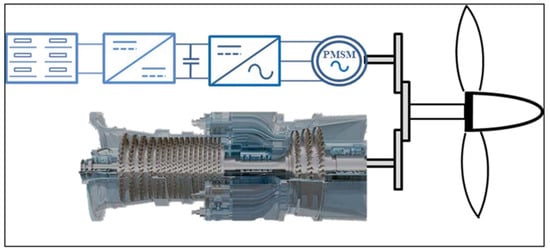
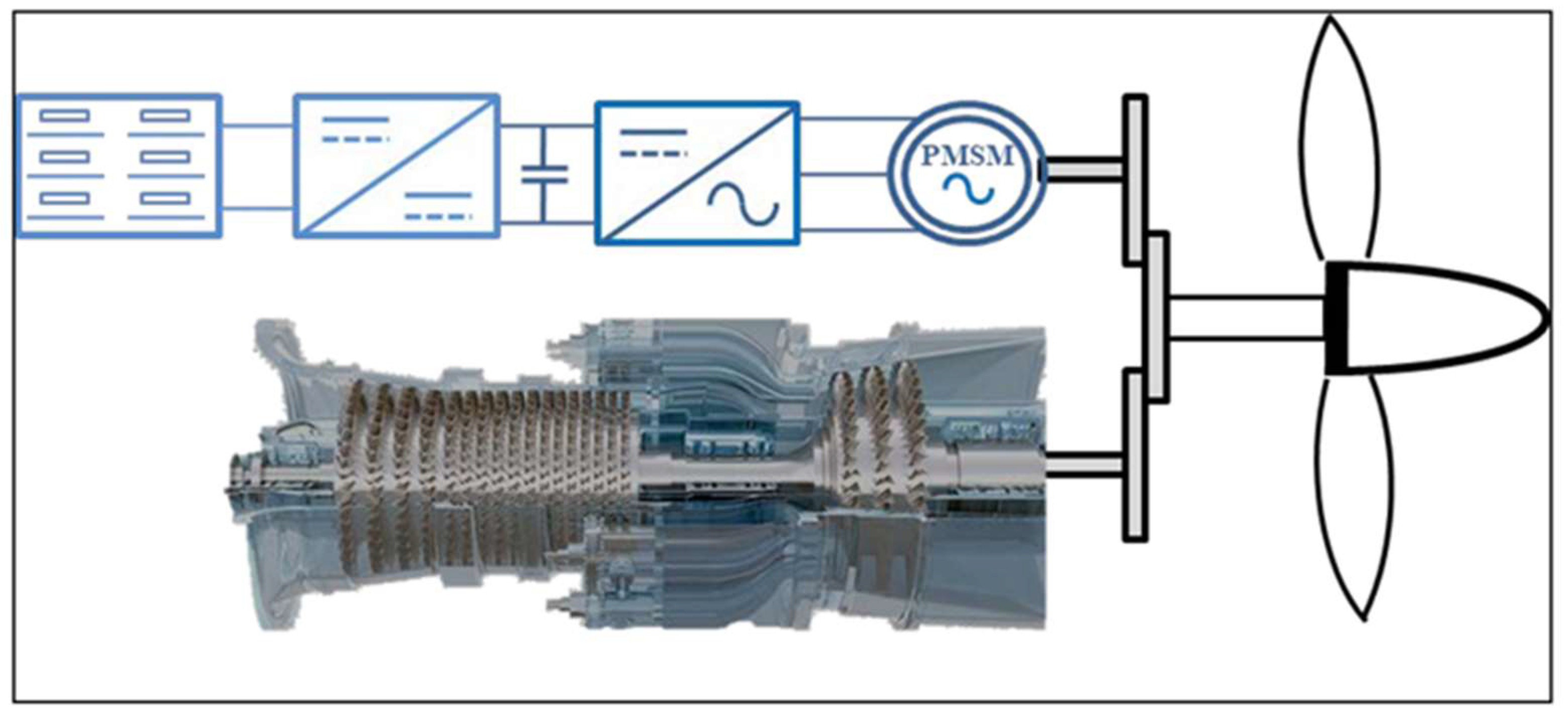
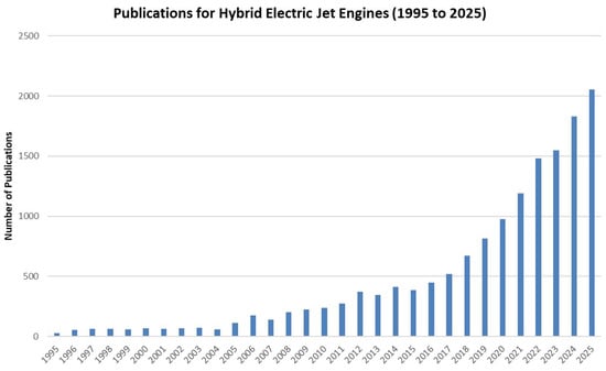
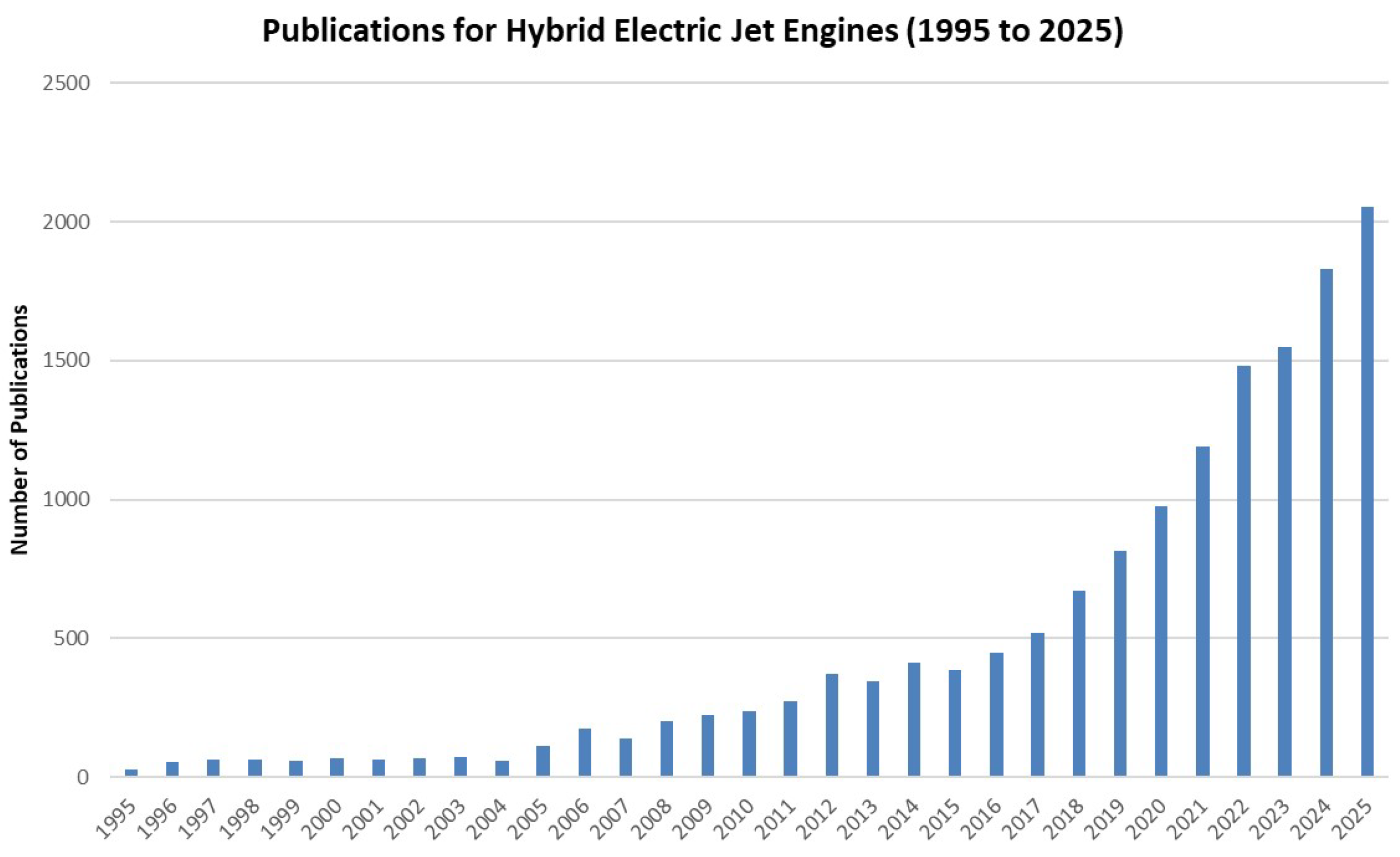
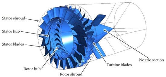
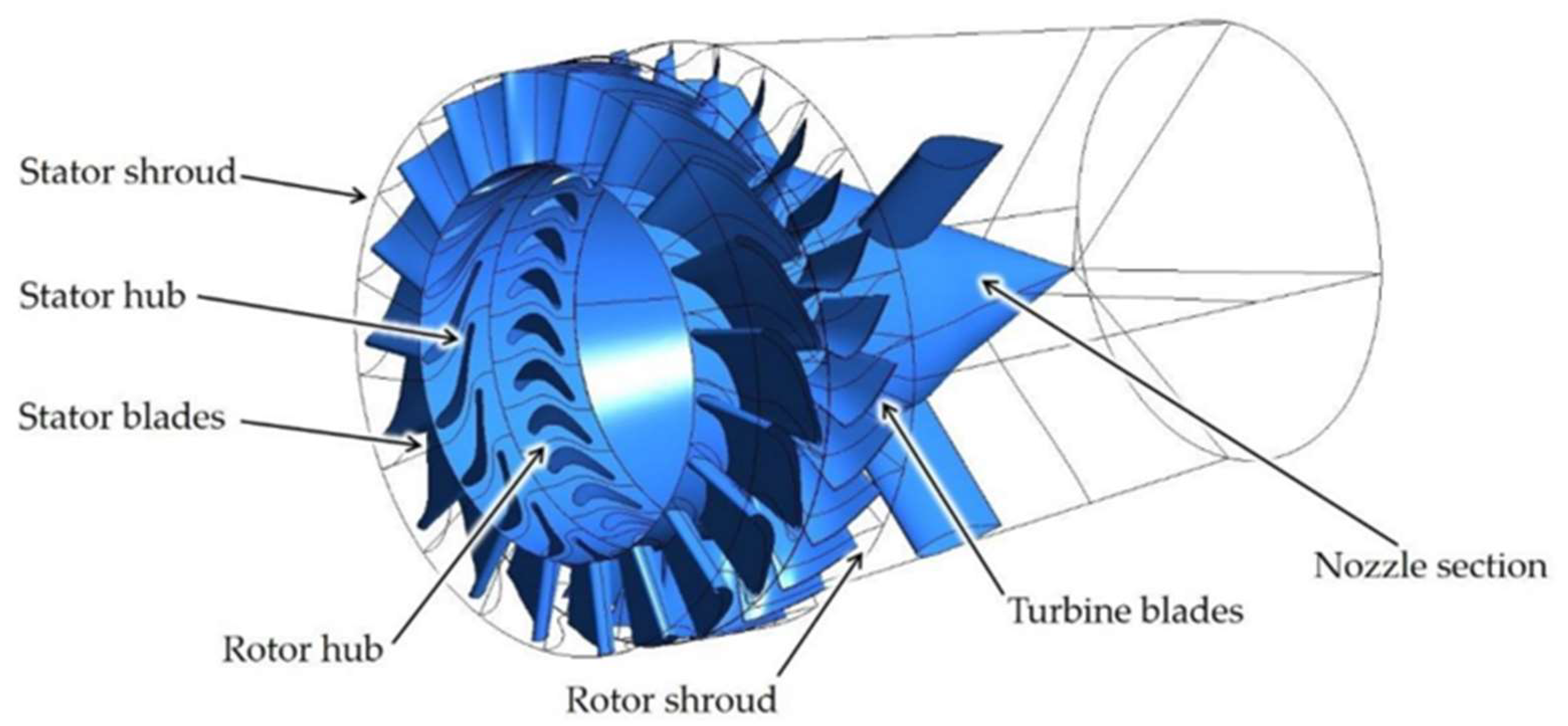
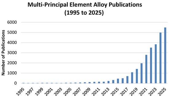
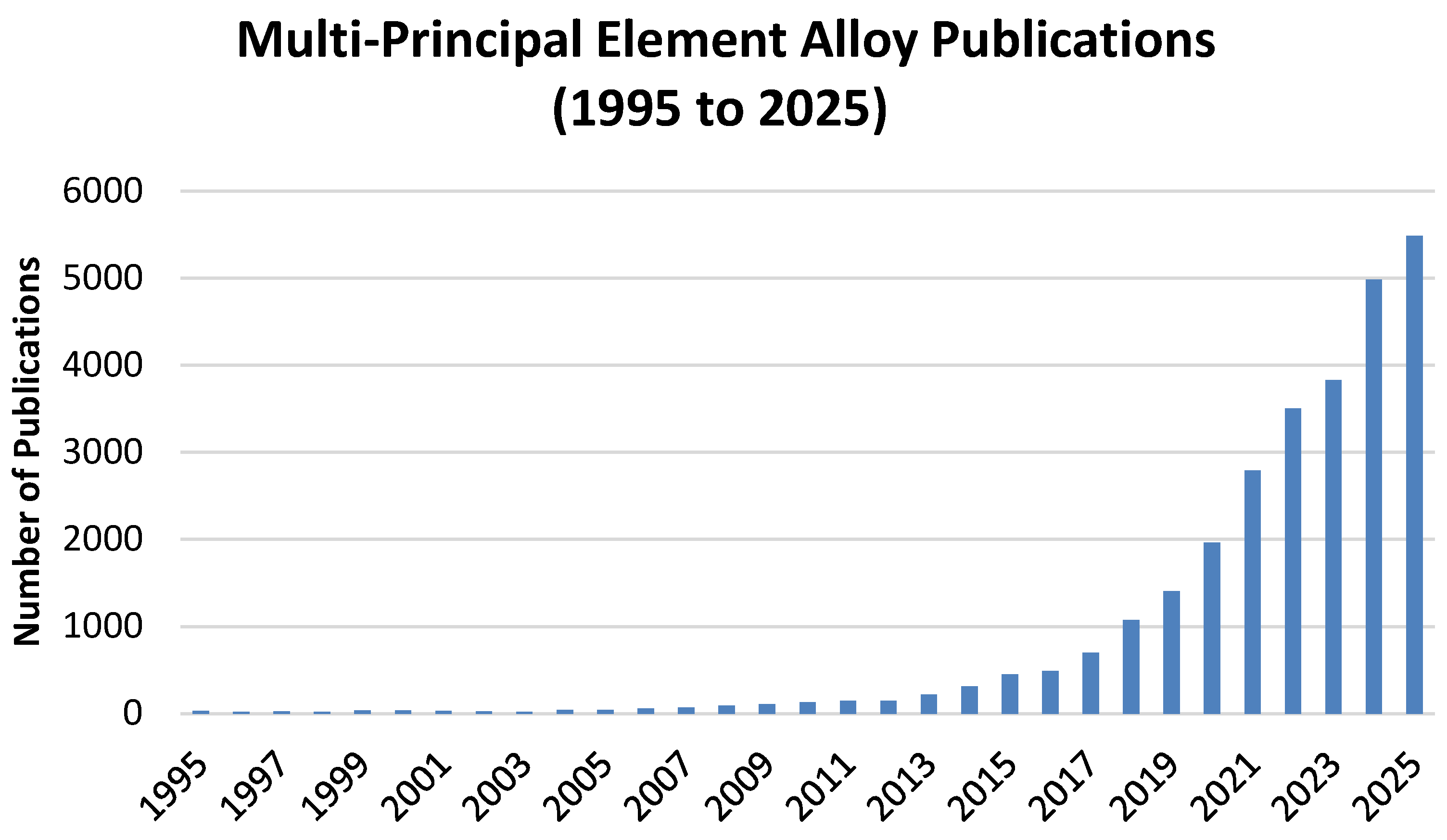
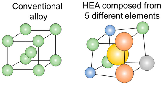
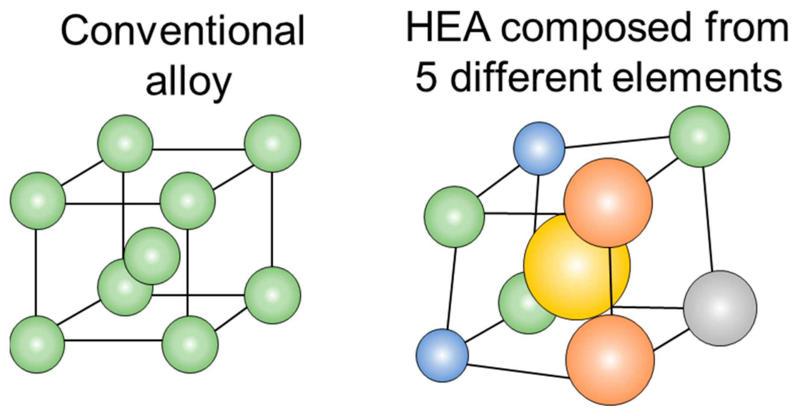
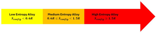
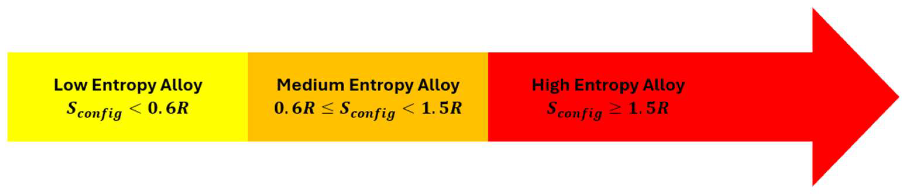
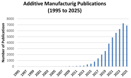
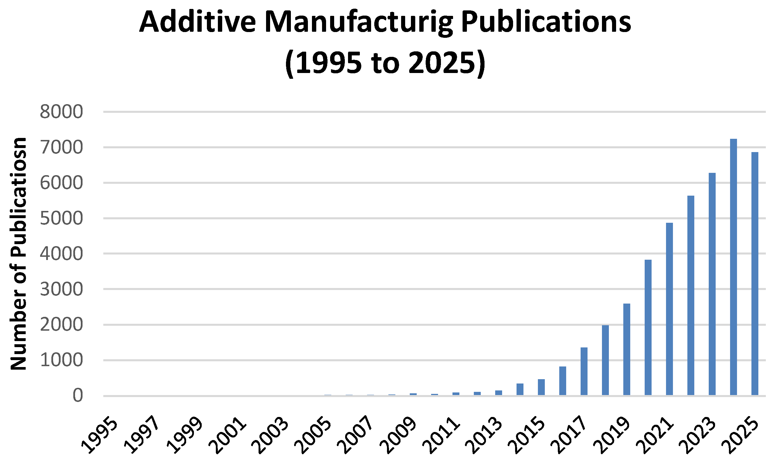
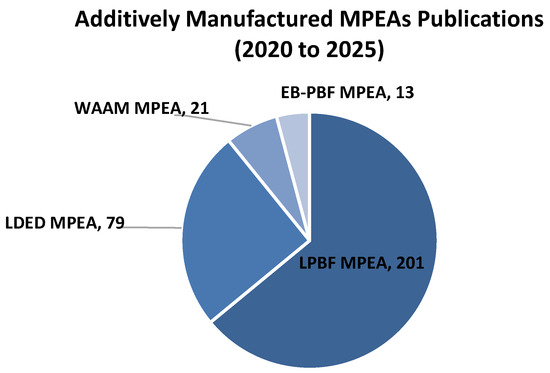
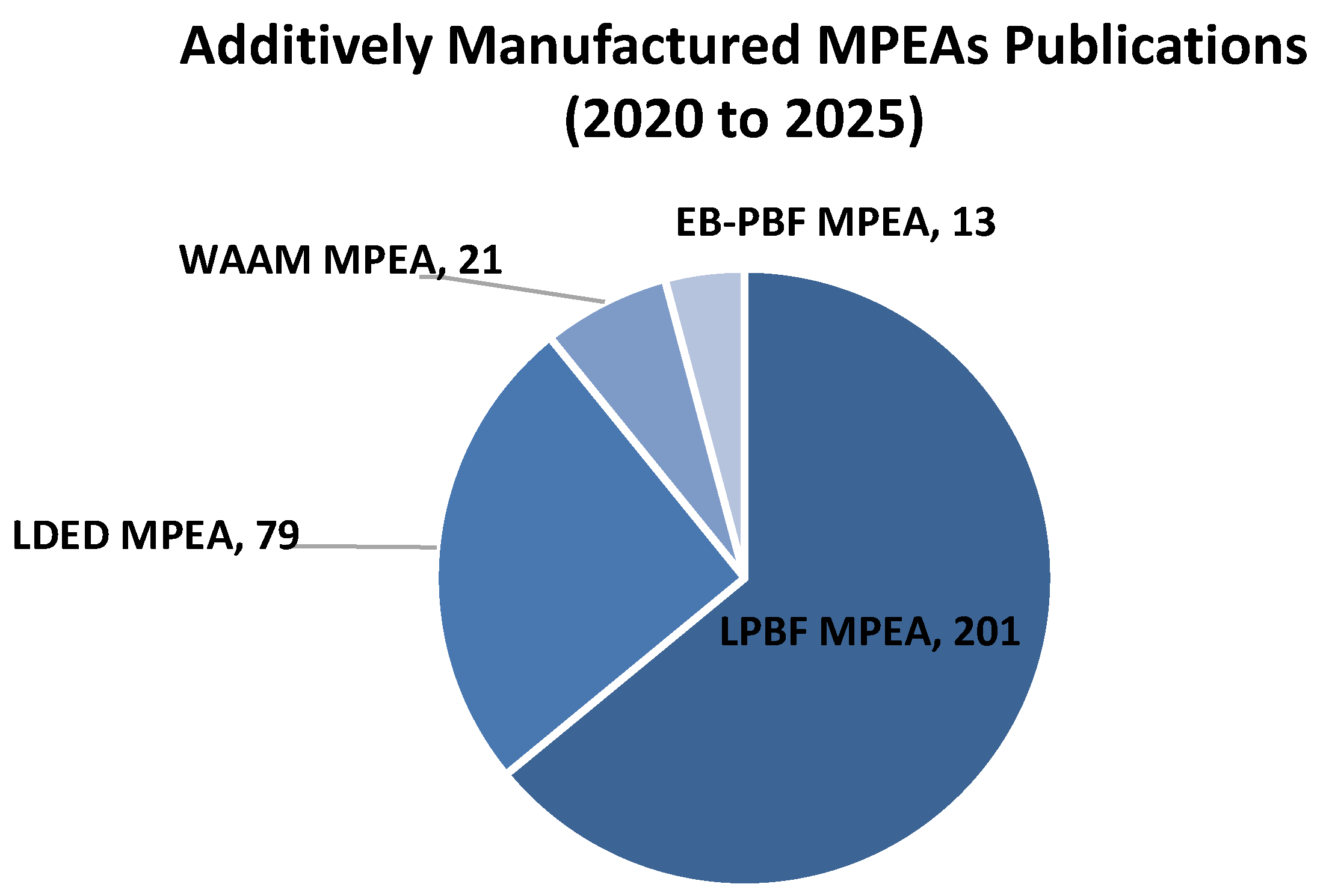
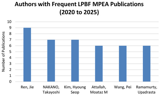
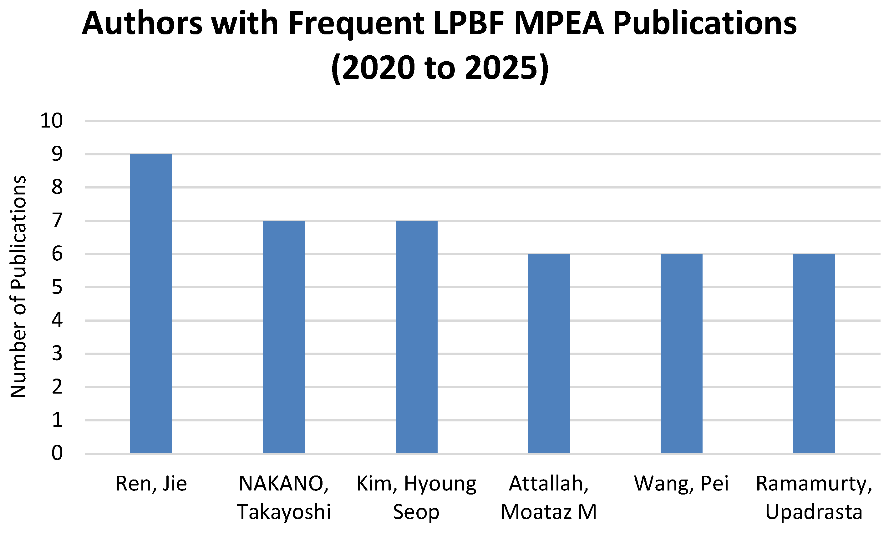
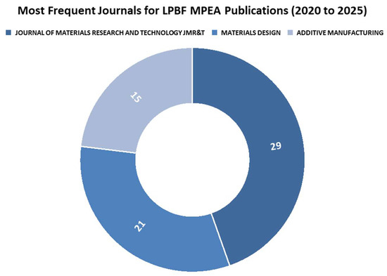
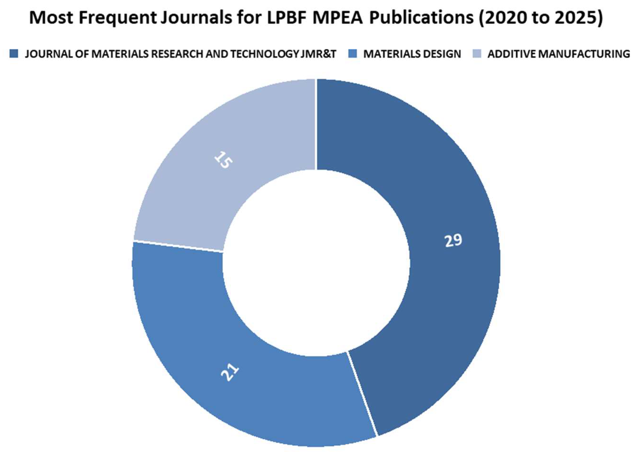
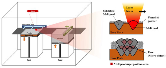
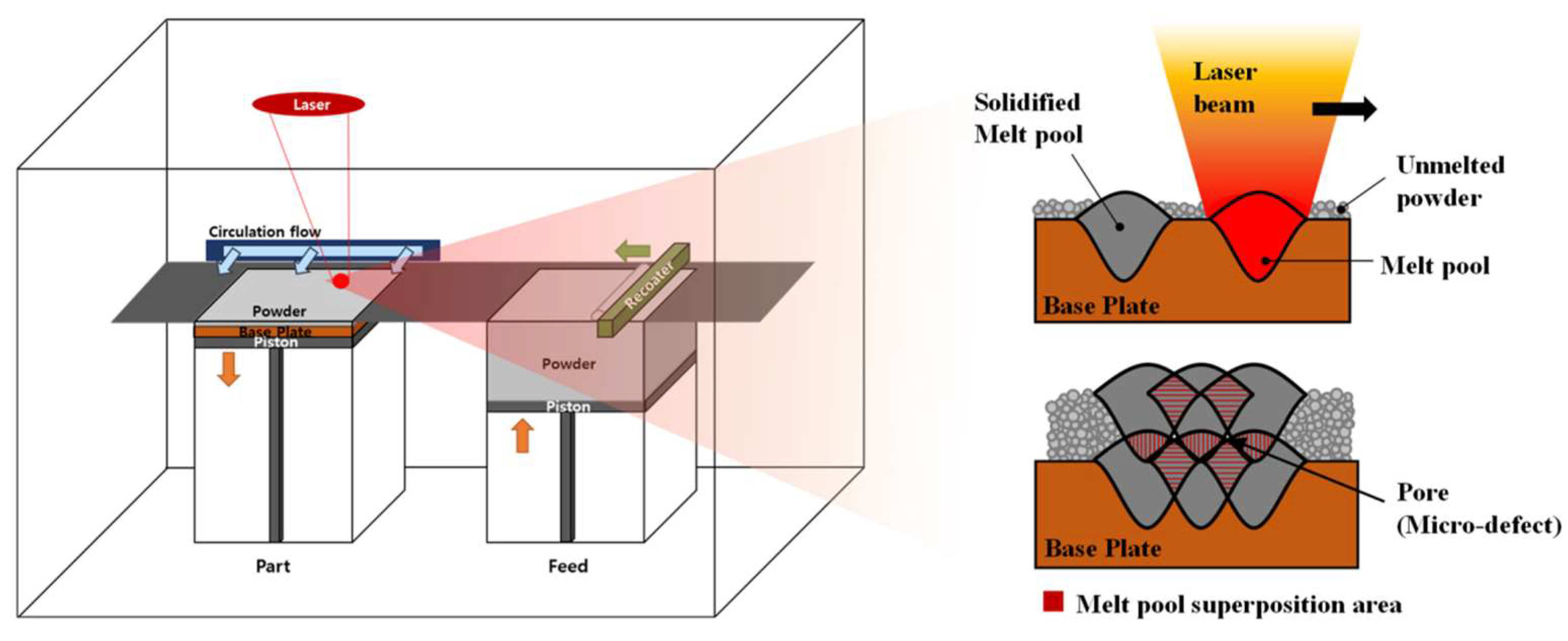
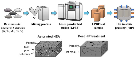
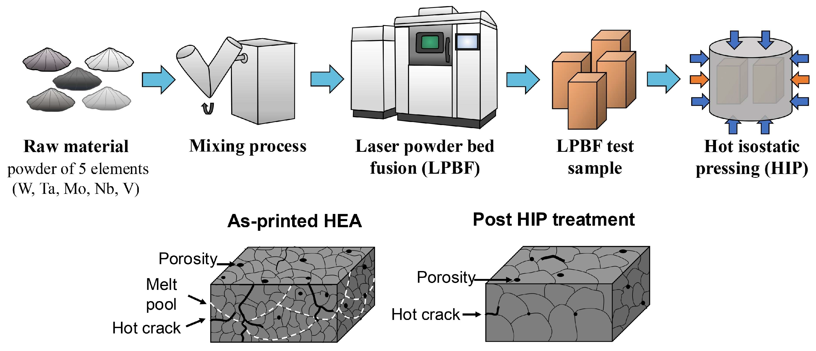
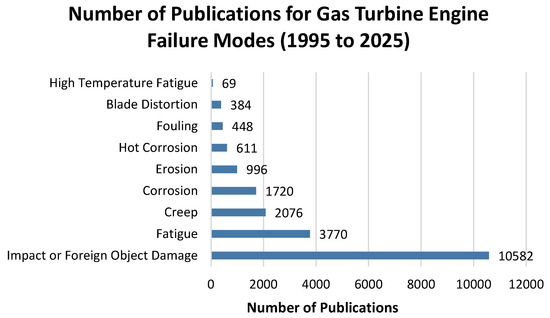
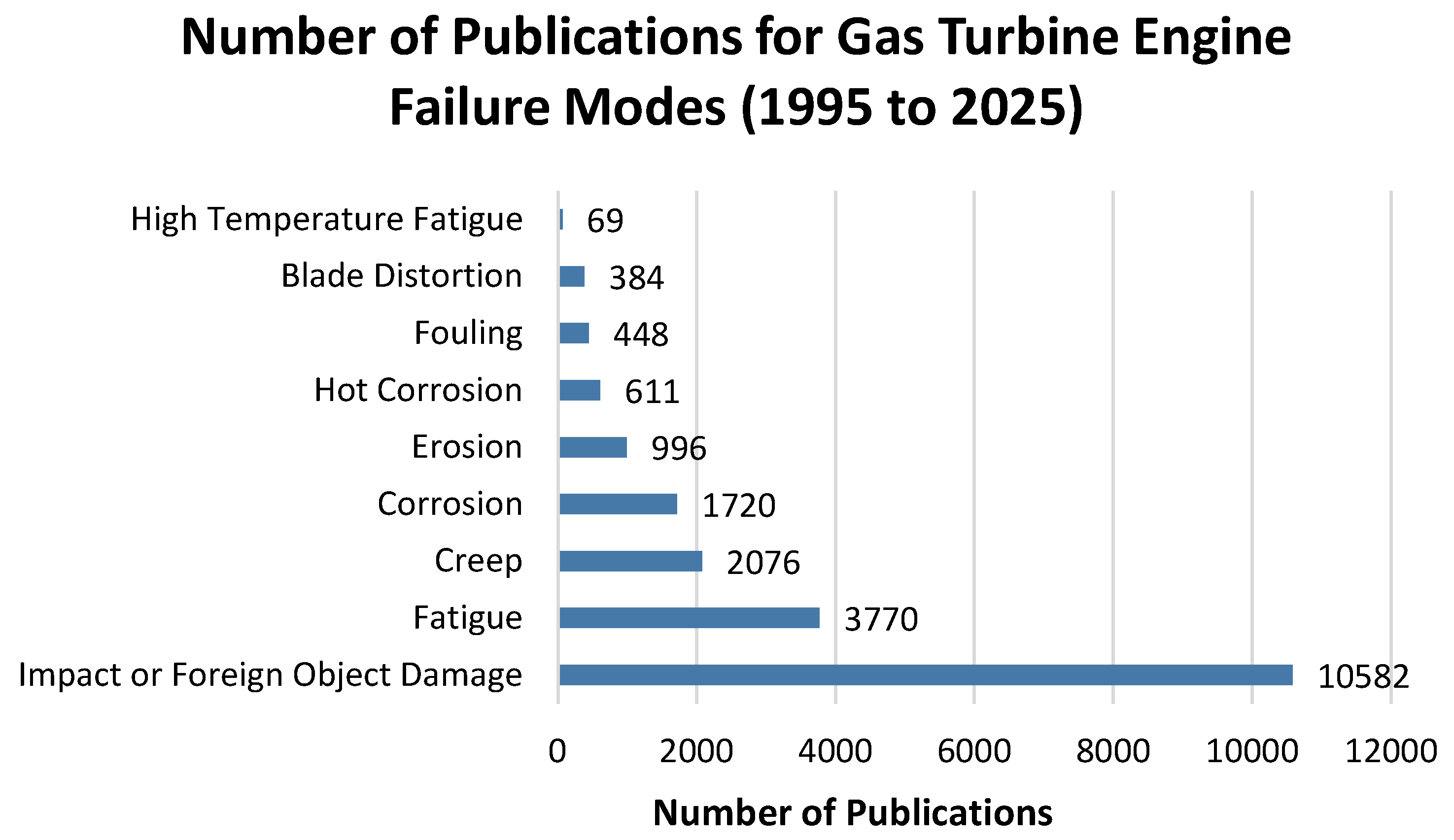
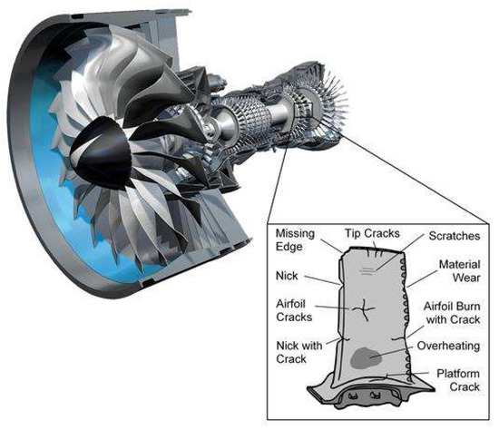
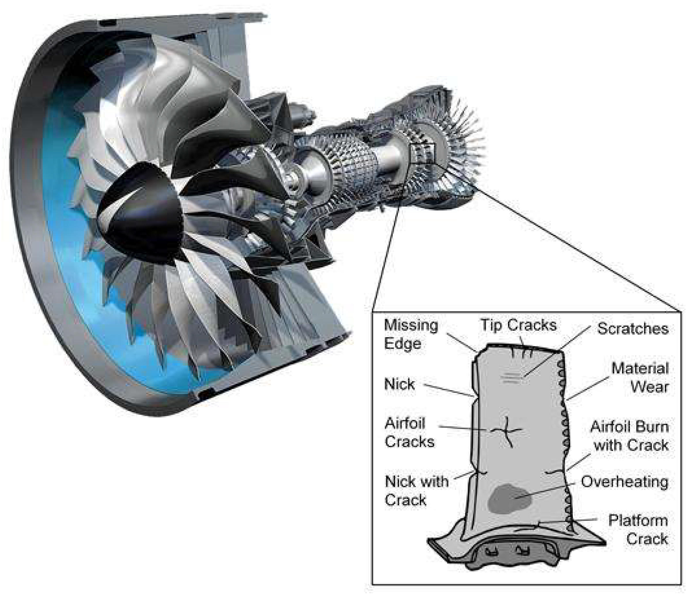
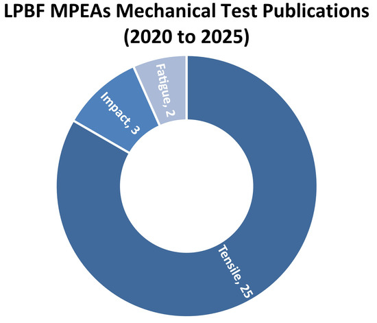
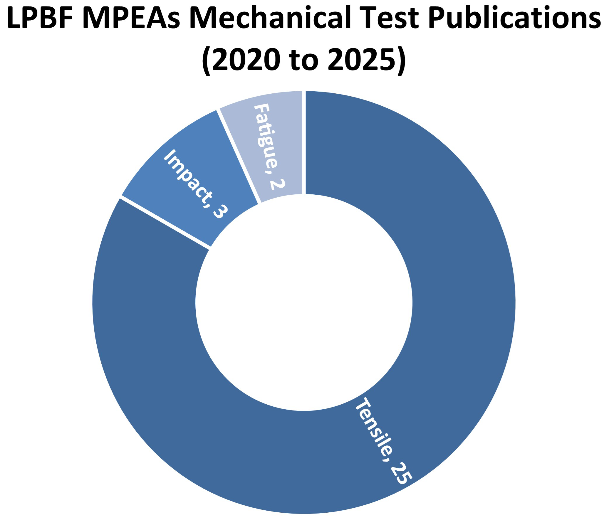
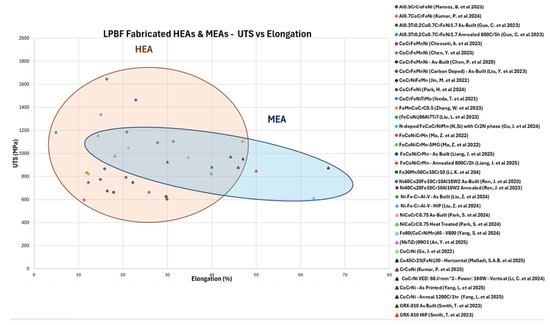
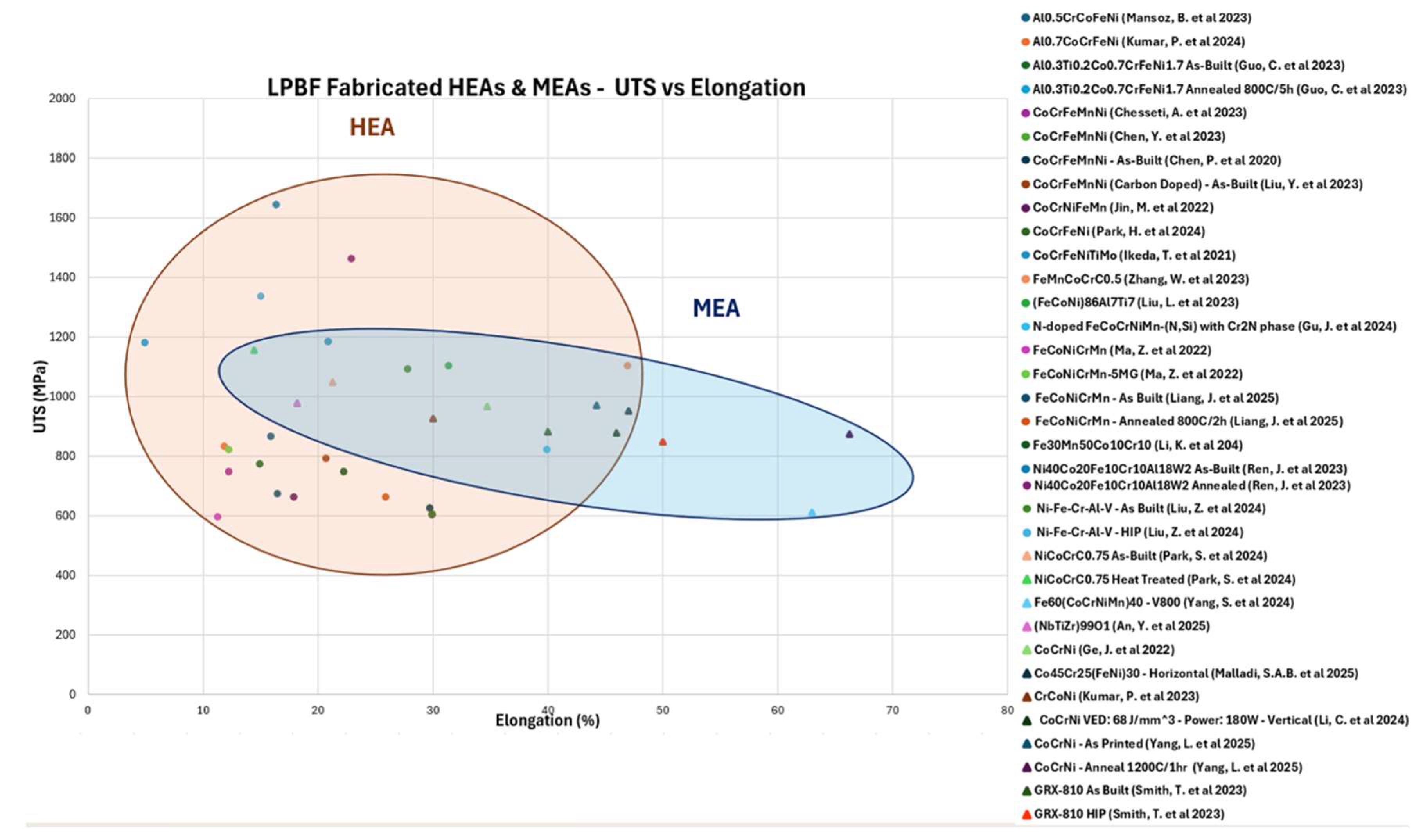

Disclaimer/Publisher’s Note: The statements, opinions and data contained in all publications are solely those of the individual author(s) and contributor(s) and not of MDPI and/or the editor(s). MDPI and/or the editor(s) disclaim responsibility for any injury to people or property resulting from any ideas, methods, instructions or products referred to in the content. |
© 2026 by the authors. Licensee MDPI, Basel, Switzerland. This article is an open access article distributed under the terms and conditions of the Creative Commons Attribution (CC BY) license.