


Abstract
As Global Navigation Satellite Systems (GNSSs) underpin safety-critical infrastructure, their vulnerability to sophisticated spoofing attacks poses severe physical layer security risks. To address the limitations of existing single-antenna defense mechanisms, this paper proposes a rigorous instantaneous spoofing detection framework utilizing a novel “one-primary-two-auxiliary” three-antenna configuration. By embedding the rigid baseline length as a hard geometric constraint into the Integer Least Squares (ILS) model, we derive a specialized constrained LAMBDA algorithm that significantly shrinks the ambiguity search space. A rigorous hypothesis testing mechanism is established based on the Sum of Squared Residuals (SSR), analytically deriving the detection threshold from the central Chi-square distribution and analyzing the sensitivity via the non-central parameter. Through conducting field experiments using commercial receivers and professional GNSS signal simulators, the proposed method was validated using both single-satellite spoofing and full-constellation spoofing scenarios. Results demonstrate that the system achieves a Minimum Detectable Deviation (MDD) of spatial direction as low as and maintains an empirical detection rate of >99% with a negligible false alarm rate. Notably, the method exhibits instantaneous response capabilities, effectively identifying both single-satellite and full-constellation spoofing attacks within a single epoch without requiring prior attitude information or external aiding.
1. Introduction
With the widespread application of Global Navigation Satellite Systems (GNSSs) in key infrastructure sectors such as aerospace, transportation, power communications, and national defense, the reliability of positioning and timing has become increasingly important [1]. However, GNSS signals are weak when they reach the ground, and their signal structure is publicly accessible, making them highly vulnerable to various types of intentional interference [2,3]. Among these, spoofing interference involves the transmission of counterfeit signals that closely resemble the real signal structure, which misleads the receiver’s tracking loop to lock onto incorrect signal parameters, resulting in concealed deviations in positioning solutions, or even complete takeover of the system [4,5]. Compared to simple jamming interference, spoofing is more covert and dangerous. Therefore, efficiently and robustly detecting and mitigating spoofing signals has become a critical issue in the field of satellite navigation security [6,7].
Current spoofing detection techniques can be broadly categorized into two main types: signal processing-based methods and navigation solution-based methods [8,9]. Single-antenna receivers typically rely on methods such as signal power monitoring and Signal Quality Monitoring (SQM), but their detection performance is often limited when confronted with sophisticated spoofing signals that control power precisely [10,11,12]. In contrast, multi-antenna array technology takes advantage of the differences in the Direction of Arrival (DOA) between real signals and spoofing signals, offering more distinct distinguishing features in the spatial domain [13,14]. Since spoofing signals usually come from a single transmission source, all counterfeit satellite signals will have the same direction vector when they reach the receiver’s antenna array. This is in stark contrast to the real satellite signals, which originate from different spatial directions and thus exhibit different geometric characteristics [15].
Despite the inherent advantages of multi-antenna direction-finding techniques in countering spoofing, practical applications still face challenges. Traditional interferometric methods rely on carrier phase measurements, and resolving the carrier phase integer ambiguity is a prerequisite for achieving high-precision baseline vector estimation. In environments with low signal-to-noise ratios or interference, rapidly and correctly resolving the ambiguity becomes difficult. If the ambiguity resolution is incorrect, baseline estimation will incur significant errors, directly affecting the accuracy of spoofing detection [16,17].
In recent years, multi-antenna techniques have become a focal point in GNSS spoofing detection research due to their ability to exploit spatial domain features. State-of-the-art methods primarily include Controlled Reception Pattern Antennas (CRPA) [18], DOA estimation [19], spatial correlation-based detection [20], and inter-receiver consistency monitoring [21]. While CRPA and DOA techniques provide robust defense mechanisms by utilizing spatial filtering and beamforming, they typically require bulky antenna arrays, expensive coherent multi-channel Radio Frequency (RF) front-ends, and complex pre-calibration procedures. Furthermore, spatial correlation methods often rely on multi-epoch smoothing to achieve convergence, resulting in inevitable detection latency.
To overcome these limitations, this paper proposes a novel “one-primary-two-auxiliary” heterogeneous three-antenna configuration. Compared to existing state-of-the-art techniques, the technical advancements of this work are threefold:
- (1)
- Single-epoch instantaneous detection latency: By embedding a rigid baseline geometric constraint into the ambiguity search process, the proposed method eliminates the need for multi-epoch smoothing, achieving instantaneous spoofing detection within a single epoch.
- (2)
- Low hardware complexity via a heterogeneous architecture: Unlike traditional shared-clock systems that require multi-channel coherent RF front-ends, our architecture allows independent, non-synchronized clocks between the primary receiver and the auxiliary baseline, enabling a plug-and-play upgrade for existing single-antenna infrastructure.
- (3)
- High detection sensitivity: Supported by a rigorous SSR hypothesis testing mechanism, the system achieves a MDD of spatial direction as low as 0.33° with a 2-m baseline, without requiring prior attitude information or external Inertial Navigation System (INS) aiding.
Unlike traditional dual-antenna direction-finding methods which often require prior attitude knowledge or suffer from integer ambiguity resolution difficulties in single-epoch processing, the proposed three-antenna configuration utilizes the known baseline length as a rigid geometric constraint. This constraint significantly shrinks the ambiguity search space, allowing for robust spoofing detection even using low-cost receivers without external attitude aiding.
This paper incorporates the auxiliary baseline information as a constraint within an ILS problem [22]. By using an improved baseline-constrained LAMBDA algorithm and taking advantage of the correlation between ambiguities across different baselines, the success rate of integer ambiguity resolution is significantly improved [23]. Based on this, the correctly resolved ambiguities are used to calculate high-precision baseline vectors, and a Chi-square test statistic based on the sum of squared residuals is constructed [24]. Theoretical analysis, field experiments, and full-constellation simulations show that, in the presence of spoofing signals, significant non-centralized deviations occur between the floating point solution and the final solution obtained with the constraint, thus enabling effective identification of spoofing attacks. This method not only improves the redundancy and strength of the observation equations in terms of the mathematical model but also achieves robust detection of GNSS spoofing signals through a simple hardware configuration at the physical layer.
While our previous work [15] demonstrated the feasibility of three-antenna spoofing detection, it relied on a shared-clock receiver architecture where all three antennas were connected to the same hardware platform. This requirement significantly limits practical deployment, as it necessitates replacing the user’s existing GNSS receiver with a specialized multi-antenna unit.
This study addresses this limitation by introducing a heterogeneous receiver architecture, specifically a “one-primary-two-auxiliary” configuration, in which the user’s existing single-antenna receiver operates alongside a dedicated auxiliary baseline module. This configuration introduces two technical challenges absent in [15]: (i) inter-receiver clock synchronization across independent oscillators, and (ii) inter-receiver bias (IRB) modeling in the stochastic model. We resolve these through a Doppler-based phase interpolation strategy and rigorous cross-correlation modeling. The resulting framework enables spoofing detection as a retrofit upgrade to existing infrastructure without hardware replacement, substantially broadening the applicable deployment scenarios.
2. Auxiliary Baseline Three-Antenna Configuration and Observation Equation
2.1. Introduction to the Auxiliary Baseline Three-Antenna Configuration
This paper proposes a spoofing detection method based on auxiliary baselines, with the antenna configuration shown in Figure 1. The configuration adopts a three-receiver antenna array topology, consisting of one user antenna (Antenna 3) as the primary positioning reference and two auxiliary antennas (Antenna 1 and Antenna 2). The baseline between Antenna j and Antenna i is referred to as baseline ij; for example, the baseline between Antenna 1 and Antenna 2 is denoted as b12. The length of the auxiliary baseline b12 is known, while the lengths of baselines b13 and b23 are unknown. This configuration is very suitable for common application scenarios where the length of the auxiliary baseline can be precisely known in advance, while the user’s position remains uncertain [25].
Figure 1.
Three-antenna configuration diagram of auxiliary baseline.
In practical deployments, the auxiliary antennas are rigidly mounted on a bracket constructed from high-strength alloy metals (e.g., aluminum alloy). It is important to note that for a short baseline of 1 to 2 m, the structural deformation (such as thermal expansion) and mechanical vibrations induced by the environment are typically on the sub-millimeter scale. Since these physical variations are significantly smaller than the intrinsic GNSS carrier phase measurement noise (which is generally at the millimeter level), they are naturally absorbed by the observation noise covariance matrix. Therefore, their impact on the baseline estimation and the subsequent detection statistic is negligible. Consequently, the baseline length L can be robustly treated as a perfectly known and absolute constant in the mathematical constraints without compromising the system’s detection performance.
A critical barrier to the widespread adoption of traditional multi-antenna spoofing defense systems is their reliance on a shared-clock architecture. In such systems, all antenna elements must be connected to a centralized, multi-channel RF front-end driven by a single local oscillator to maintain strict phase coherence. This paradigm is highly impractical for upgrading existing critical infrastructure, as it forces users to discard their deployed single-antenna receivers and invest in entirely new, expensive array equipment.
In contrast, the heterogeneous receiver architecture proposed in this paper significantly improves engineering practicality. The primary antenna (representing the user’s legacy receiver) and the auxiliary baseline (the add-on dual-antenna module) operate on independent, non-synchronized oscillators. To address the resulting clock discrepancies, we implement a software-based Doppler phase interpolation strategy. This design decouples the anti-spoofing module from the core navigation receiver at the hardware level, transforming the three-antenna configuration into a low-cost, plug-and-play solution that can be seamlessly retrofitted onto existing GNSS infrastructure.
The core geometric feature of this configuration is the known and fixed short baseline b12 between the two auxiliary antennas. In the mathematical model and signal processing, this known length is used as a strong geometric constraint [26,27]. When solving for the longer baseline b23 formed by the user antenna and the auxiliary antennas, this constraint allows for rapid validation of the observation values, thus enabling more efficient integer ambiguity resolution and the identification of spoofing interference signals with abnormal spatial characteristics.
2.2. Three-Antenna Model with Auxiliary Baseline Constraints
GNSS observations consist of two types: pseudorange and carrier phase. The observation accuracy of pseudorange is typically on the order of meters or decimeters, while the observation accuracy of carrier phase can reach millimeters [28,29]. The double-differenced (DD) equations for the two types of observations can be written as the following linearized system of equations:
where E represents the mean or expected value of the observations. D represents the variance of the observations. y is the m-dimensional vector of double-differenced carrier phase or pseudorange observations. a is the vector of ambiguities to be resolved, with units expressed as integer multiples of wavelengths. b is the baseline vector, which is unknown in the GNSS observation equation but can be precisely measured in advance with other tools. B is the geometry matrix for the satellite signals, also known as the direction cosine double-difference matrix. A is the design matrix, which includes the signal wavelength and is related to the signal frequency.
For applications involving short baselines (from a few meters to several kilometers), the atmospheric effects on observations from multiple antennas can be assumed to be almost identical [30]. The variance of y is represented by the matrix , which is known.
Equation (1) is a linear system, and its numerical solution can be obtained using the least squares method:
For common scenarios where the antennas are fixed, the baseline length is typically known. This precise prior information can be used to constrain the baseline equations. The baseline length can be represented as , and incorporating this information into the standard GNSS model can improve the success rate of integer ambiguity resolution, thereby enhancing the accuracy of the baseline vector b. In this case, the baseline model with length constraint can be expressed as:
where Z represents integers and R represents real numbers. The strict least squares solution to Equation (3) can be written as:
This least squares solution can be referred to as the least squares problem with quadratic constraints [31].
In general, the positions of the user antenna and the auxiliary baselines are relatively close, as shown in Figure 1. Therefore, the design matrix A, the geometry configuration matrix B, and the variance matrix can be considered identical. In this case, the observation equations between the three antennas have the following relationship:
where F is the data matrix that contains the baseline vector b, ambiguity vector a, and DD observation vector y. This equation shows that only two of the three DD data points are independent. Therefore, in the subsequent equations, we will only consider two DD data points. Taking y12 and y23 as examples, the mean of the observation equations y12 and y23 can be described as:
Since y12 and y23 share a common antenna (Antenna 2), there is a correlation between their observation data [32]. Considering the common reference antenna, the noise correlation coefficient between the two auxiliary baselines is 0.5, leading to the weight matrix and the variance-covariance matrix for the observation equations can be expressed as:
Here, denotes the Kronecker product. The result of Equation (7) is:
For the baseline b, the least squares solution corresponding to Equation (4) is denoted as the floating point solution and , and the floating point solution can be obtained from the following normal equation:
The floating point solutions and can be written as:
where . The orthogonal projection matrices , . , and .
According to the law of error propagation, the covariance matrix of the floating point solutions and is given by the following formulas:
Considering the correlation induced by the shared antenna, we can derive the covariance matrix between different baselines from Equation (12):
From Equation (11), we can see that the precision of the floating point solutions and is generally not high. Especially in conditions of poor signal quality or in the presence of spoofing interference, the variance matrix of the observations increases significantly, leading to a notable degradation in the precision of the floating point solutions and .
When the integer ambiguities are known, the conditional solution for the baseline vector and its corresponding covariance matrix can be expressed as:
From Equation (12), we can see that is smaller than . In other words, correctly resolving the integer ambiguity can significantly improve the accuracy of the baseline vector estimation [33]. From the covariance matrix, it is clear that the precision of the floating point solution and , as well as the conditional solution , depends on the satellite geometry and the level of observation noise. When GNSS signal quality is poor or spoofing interference is present, the variance matrix increases significantly, which leads to a substantial reduction in the precision of the floating point solutions and , and the conditional solution [34].
Therefore, it is essential to explore how to effectively utilize the known information from auxiliary antennas to enhance the observation equation, fully leverage the integer characteristics of the ambiguity, and use the precise auxiliary baseline length to improve the solution accuracy. This will, in turn, enhance the resistance of the three-antenna configuration to spoofing interference.
3. Auxiliary Baseline Three-Antenna Model Solution and Spoofing Detection Principles
3.1. Least Squares Solution Process of Auxiliary Baseline
In this section, we will fully utilize the integer characteristics of the two ambiguities and the known length of one auxiliary baseline to effectively constrain the observation equations, thereby enhancing the baseline observation accuracy and anti-jamming capability. By embedding three constraints into the observation equations, redundancy is introduced, significantly improving the robustness of the system and resulting in more accurate solutions.
By embedding the integer characteristics of a12, a23 and the known length l of b12 into Equation (2), we obtain the following:
where is the known length of the auxiliary baseline b12, and the conditional solution for b23, denoted as is given by:
From Equation (15), it can be seen that the covariance matrix for is . This shows that by fully utilizing the length constraint of b12, we can improve the precision of to . In other words, the prior information about b12 also improves the accuracy of b23.
The constrained solution for Equation (14) can be performed in the following steps. The corresponding flowchart is shown in Figure 2.
Figure 2.
Flowchart for solving with auxiliary baseline constraint method.
First, use the known baseline length l to obtain the conditional solution for :
Then, use the LAMBDA method with baseline constraints to search for the integer ambiguity vectors , [35]. In the ILS problem, the search space for integer ambiguities geometrically constitutes a hyper-ellipsoid. When dealing with a short baseline, the sheer volume of candidate sets within this hyper-ellipsoid can be overwhelmingly large, especially under high-noise environments. In our constrained LAMBDA approach, the known rigid baseline length L is integrated as a non-linear equality constraint, which represents a sphere in the spatial domain. By intersecting the standard hyper-ellipsoid with this geometric sphere, the ambiguity search space is drastically reduced to the boundary of the intersection. This rigorous geometric constraint securely filters out invalid integer candidates, thereby ensuring a high single-epoch fixing success rate.
The standard unconstrained LAMBDA algorithm is already highly efficient. By introducing the rigid baseline length constraint, the volume of the ambiguity search space (and thus the number of candidate nodes to be evaluated) is drastically reduced. Consequently, the computational complexity is actually decreased compared to standard RTK processing. This ensures that the single-epoch detection can be effortlessly executed in real-time (typically requiring < 10 ms per epoch on a standard commercial processor).
This means using the constraint from baseline b12 in combination with the ambiguity vector of baseline b23, as well as the correlation between the two baseline ambiguities, to enumerate the ambiguities. The vectors and can be obtained as:
As described in Section 2.2, correctly resolving the ambiguity significantly improves the precision of baseline vector estimation. Using the ambiguity vector obtained from the solution, the final solution for baseline can be obtained as:
Using and , the final solution for baseline b23 can be obtained as:
The final solution for fully utilizes the integer characteristics of the two ambiguities and the known length of the auxiliary baseline. This enhances the strength of the observation equations, leading to improved precision. In subsequent simulations, it will be shown that even in conditions of poor signal quality or spoofing signal interference, can achieve accurate results, demonstrating its resistance to interference. Thus, we can regard it as a valid substitute for the true value.
3.2. Spoofing Detection Algorithm Analysis
When all received signals are real, the floating-point solution for follows a Gaussian distribution, denoted as . We consider the final solution as a high-precision reference under nominal conditions. The normalized sum of squared residuals S between the final solution and the floating-point solution can be expressed as:
Strictly speaking, the float baseline and the constrained fixed baseline are estimated from the same GNSS observations, making them statistically dependent. According to estimation theory, the exact covariance of their difference is given by . However, in the proposed configuration, is rigorously bounded by both the fixed integer ambiguities and the rigid physical length constraint L of the metal bracket. Consequently, its spatial uncertainty is negligible compared to the covariance of the unconstrained float solution . Therefore, the relationship simplifies to . Adopting as the weighting matrix provides a mathematically robust and slightly conservative approximation for the test statistic. This assumption is further validated by the Monte Carlo distribution analysis in Section 4, which confirms that S strictly adheres to the central distribution under normal conditions. This approximation is a standard practice in constrained GNSS estimation when the constraint is significantly more precise than the observations.
The test statistic for spoofing detection is constructed based on the SSR. The estimated baseline vector inherently possesses three independent spatial coordinate components (e.g., East, North, Up). After normalizing the residual vector by its covariance matrix, the error components across these three spatial dimensions can be approximated as three independent standard normal variables . According to statistical theory, the sum of the squares of three independent standard normal variables rigorously follows a central Chi-square distribution with 3 degrees of freedom, denoted as , under the null hypothesis (absence of spoofing).
Here, normalizes the residuals of the baseline components, and S is expected to follow a chi-squared distribution with 3 degrees of freedom, denoted as [36].
In the presence of spoofing signal interference, the spoofing signal takes over the tracking loop of the real signal, causing a shift in the GNSS signal observations and introducing significant errors in the floating-point solution (where p denotes the spoofing scenario). In this case, is expressed as . Δb represents the deviation of the baseline vector floating-point solution due to the spoofing signal. The normalized sum of squared residuals Sp between and can be written as:
This residual Sp is expected to follow a non-central chi-squared distribution with a non-centrality parameter γ, denoted as . The non-centrality parameter γ is defined as:
From the above analysis, it is evident that the residuals for real signals and spoofing signals follow different distributions. When spoofing signals are present, Sp will significantly increase. Therefore, by setting an appropriate threshold under a given false alarm rate (e.g., 10−4), spoofing signals can be effectively detected.
3.3. Integrity and Reliability of Single-Epoch Ambiguity Resolution
To ensure the reliability of the instantaneous spoofing detection, the integrity of the single-epoch ambiguity resolution must be rigorously monitored. In this framework, the standard Ratio Test is employed as the primary integrity metric, with a predefined threshold of to validate the fixed integer candidate against the second-best alternative. By integrating the rigid auxiliary baseline length L as a hard geometric constraint, the volume of the ILS search space is significantly reduced, which theoretically minimizes the probability of a wrong-fix (false-fix risk).
However, it is essential to re-evaluate the detection performance under potential wrong-fix cases. In severe signal-degraded or high-multipath environments, if an incorrect integer set bypasses the Ratio Test, the resulting baseline vector will deviate significantly from the true geometry. Consequently, the test statistic S will surpass the detection threshold Sth, triggering a spoofing alarm. While this ensures that no compromised solution is accepted as authentic, it inherently increases the False Alarm Rate (FAR) under poor signal conditions. Thus, the rigid baseline constraint acts as a double-layered defense: it both improves the fixing success rate and ensures that any integrity failure in the ambiguity domain is conservatively captured by the spoofing detection module.
To provide a compact quantitative indicator under the tested conditions: in the 3600-epoch open-sky field experiment (Section 5.1), the ambiguity fix rate achieved with the Ratio Test (threshold = 3.0) and baseline length constraint was 98.7%, and zero wrong-fix events were observed throughout the entire data collection period. This implies an empirical wrong-fix rate of (95% confidence upper bound). The observed false alarm rate of ≤0.028% is therefore attributable to multipath transients rather than wrong-fix events, confirming that the Ratio Test reliably guards against integrity failures under nominal signal conditions.
4. Simulation and Validation
To validate the correctness of the algorithm, we first use simulated data generated by the Monte Carlo method to test the model. The simulated GNSS data is based on the receiver’s position and the positions of the GNSS satellites. The baseline b12 has a length of l = 1 m, and the simulation involves 8 GPS satellites. The corresponding signal frequency is L1, with a wavelength of approximately 19 cm. The standard deviation of the carrier phase σ is set to 2 mm [37].
The simulation includes two scenarios: one without spoofing signals and one with spoofing signals. The scenario without spoofing signals is labeled H0, where all received signals are real. In the scenario with spoofing signals, labeled H1, errors are artificially introduced in the signals from satellites G14 and G29 to simulate the presence of spoofing signals. All other parameters remain unchanged from the H0 scenario. The distribution of satellite signals for both cases is shown in Figure 3. The corresponding Position Dilution of Precision (PDOP) is approximately 2.44, with blue icons representing real signals and orange icons representing spoofed signals. The first spoofing signal (G14) has azimuth and elevation deviations of 20° and −10°, respectively, from the real signal. The second spoofing signal (G29) has azimuth and elevation deviations of −15° from the real signal.
Figure 3.
Simulated satellite signal distribution sky map.
Using Equations (20)–(22), the normalized sum of squared residuals S, Sp, and the non-centrality parameter γ are computed for both the H0 and H1 scenarios. The probability density distributions of S and are plotted in Figure 4a, while the probability density distributions of Sp and are plotted in Figure 4b.
Figure 4.
Probability density distributions of the normalized residual test statistic under different scenarios. (a) Scenario H0 (Normal Condition): The simulated distribution perfectly matches the theoretical central Chi-square distribution . (b) Scenario H1 (Spoofing Attack): The test statistic diverges significantly, following a non-central Chi-square distribution with the non centrality parameter γ ≈ 18,884.
These plots will help visualize how the residuals for real and spoofed signals differ under the two scenarios, showing the increase in the residuals due to the presence of spoofing signals, and highlighting the effectiveness of the spoofing detection mechanism based on the chi-squared distribution.
The simulation results visually demonstrate the high consistency between the Monte Carlo numerical simulations and the theoretical derivations. From the figures, it can be seen that the residual statistic distributions (solid line/shaded area) generated by the random trials perfectly overlap with the theoretical probability density function curves derived from the formulas (dashed line). This result strongly validates the correctness of the Formulas (20)–(22) derived in this paper, confirming that under both the no spoofing interference (H0) and spoofing interference (H1) hypotheses, the normalized sum of squared residuals strictly follows the central chi-squared distribution and the non-central chi-squared distribution , respectively.
In the H0 scenario (left figure), the statistic S is mainly concentrated within the range [0, 15], with the peak value around degrees of freedom k = 3. This indicates that under normal conditions, the residuals are primarily influenced by millimeter-level carrier phase measurement noise, keeping the values at relatively low levels. In contrast, in the H1 scenario (right figure), the statistic Sp undergoes a significant shift, with its distribution center moving to around 1.89 × 10⁴. This substantial change in statistical characteristics is due to the non-centrality parameter . On a physical level, this means that although the artificially introduced angular deviations are spatially limited, this geometric inconsistency is amplified in the statistical measurement space relative to the highly precise carrier phase observations, thus creating a significant deviation energy.
By comparing the axes scales of the two figures, it is clear that the statistic distribution in the H0 scenario is completely separated from the distribution in the H1 scenario in the numerical space, with no overlapping regions, demonstrating a large safety margin. The maximum residual in the H0 scenario (around 15) is much smaller than the minimum residual in the H1 scenario (around 18,000). This large distinction indicates that the detection algorithm based on the known baseline length constraint is highly sensitive to angular spoofing.
In practical engineering applications, the detection threshold Sth is determined based on the Neyman-Pearson criterion. Given a maximum tolerable FAR, Sth is computed using the inverse Cumulative Distribution Function (CDF) of the distribution. For instance, setting an empirical FAR of 10−4 yields Sth ≈ 20. It is important to note the inherent trade-off in this threshold selection: lowering Sth enhances the detection probability, making the system highly sensitive to minute spoofing spatial deviations, but it inevitably increases the false alarm rate, particularly in severe multipath environments where signal reflections may be misidentified as spoofing attacks. The spoofing attacks can be detected with empirical detection rate of >99% under the tested scenarios while maintaining an extremely low false alarm rate. This verifies the robustness of the algorithm in complex interference environments.
We quantitatively compared the statistical values in the no-spoofing (H0) and spoofing (H1) scenarios to evaluate the consistency between the simulation data and the theoretical model in Table 1. The analysis results show that in the no-spoofing scenario (H0), the simulated mean (3.0012) and variance (6.0215) are extremely close to the theoretical central chi-squared distribution values (3.0000 and 6.0000), with relative errors of only 0.04% and 0.36%, respectively. This validates the accuracy of the baseline model.
Table 1.
Quantitative comparison of statistical values under two scenarios.
In the spoofing signal scenario (H1), due to the influence of the non-centrality parameter, the statistic underwent an order-of-magnitude jump (mean rising to about 19,000 and variance rising to about 75,000). However, the relative errors between the simulated and theoretical values remain extremely low (0.01% and 0.07%, respectively).
This result not only confirms the correctness of the mathematical derivations but also quantifies the significant statistical differences between the two scenarios. It demonstrates that the algorithm has an extremely high signal discrimination capability and detection robustness.
To validate the extreme testing performance of the method proposed in this paper, we simulated the sensitivity response curve of the detection statistic S to changes in the spoofing signal’s angular deviation relative to the real signal’s incident direction as shown in Figure 5. Simulations were performed for baseline lengths of 1 m and 2 m, respectively. The x-axis represents the spatial angular deviation (in degrees) of the spoofing signal relative to the real signal’s direction, with a simulation range from 0° to 1.5°.
Figure 5.
Sensitivity analysis of the MDD under different auxiliary baseline lengths. The dashed black line represents the detection threshold (Sth = 20) determined by the predefined false alarm rate. The red and blue curves illustrate the mean detection statistic as a function of the spoofing deviation angle Δθ for L = 2 m and L = 1 m, yielding MDDs of 0.33° and 0.67°, respectively.
From the graph, it is clear that the detection statistic S exhibits a significant quadratic growth relationship with angular deviation. This indicates that the detection algorithm is highly sensitive to angular deviations, meaning even minor angular offsets are sharply amplified in the statistical domain, triggering an alert.
We define the intersection point of the statistic curve with the threshold line Sth = 20 as the system’s MDD. A smaller MDD means the system can detect more subtle spoofing attacks.
Configuration A (L = 1 m): The blue curve intersects the threshold line at approximately 0.67°, indicating that the system can detect spoofing signals with a direction deviation of just 0.67°.
Configuration B (L = 2 m): The red curve is steeper and intersects the threshold line at approximately 0.33°, reducing the MDD to 0.33°. The system’s MDD is halved, improving the detection sensitivity.
The y-axis represents the expected value of the normalized detection statistic S, while the black dashed line represents the preset alarm threshold Sth = 20, which is based on the chi-squared distribution to ensure a very low false alarm rate.
By comparing the two curves, it is evident that for the same angular deviation, the statistic values for the L = 2 m configuration are approximately four times higher than those for the L = 1 m configuration. This validates the principle of interferometric measurement: the system’s sensitivity is proportional to the square of the baseline length. Doubling the auxiliary baseline length improves the system’s angular resolution by a factor of two (with MDD reducing from 0.67° to 0.33°), significantly reducing the spoofing space available to attackers.
The sensitivity analysis results demonstrate that the baseline length-constrained three-antenna detection system achieves sub-degree-level spatial resolution. Under the enhanced configuration with L = 2 m, the system can detect weak angular deviations as small as 0.33°.
In practical applications, spoofing interference sources typically lie on the ground, while real satellites are in the sky, with the elevation difference between them usually far exceeding this MDD value (often greater than 10°). Therefore, the system offers >99% detection coverage for most generated spoofing attacks at the physical layer, highlighting the significant potential of this method in the field of precision security protection.
5. Experimental Verification
5.1. Real Signal Scenario
To comprehensively verify the robustness of the proposed algorithm under different geometric configurations, two independent test groups (Group A and Group B) were designed, each corresponding to different auxiliary baseline length constraints. The experimental environment remained consistent, with real GNSS signal collection under open sky conditions for a duration of 3600 epochs (1 h).
The experiment employed a ‘single-user + dual auxiliary’ antenna array configuration, detailed as follows: the auxiliary antennas, Ant 1 and Ant 2, were rigidly fixed on a precision-calibrated aluminum alloy bracket, ensuring that the baseline length was strictly maintained at 1 m (Group A) and 2 m (Group B). These auxiliary antennas were connected to a Unicore UM982 dual-antenna receiver (Unicore Communications, Inc., Beijing, China), while the user antenna was connected to a low-cost Unicore UM220 receiver. Compared to mixed-brand setups, this intra-brand configuration significantly reduces IRB and ensures consistent clock steering behaviors, thereby enhancing the reliability of the carrier phase double-difference observations.
Since the auxiliary array (UM982) and the user antenna (UM220) operate on independent low-cost crystal oscillators, strict hardware clock synchronization is not physically available. To mitigate the sampling time mismatch caused by the differential clock drift, a rigorous software synchronization strategy was implemented.
First, coarse alignment was achieved by matching the GPS Time (GPST) tags to align data streams within 1 ms. Second, to address the sub-millisecond fractional clock bias (), we estimated the precise receiver clock offset for each module at every epoch using the Standard Point Positioning (SPP) solution. The raw carrier phase observations () were then interpolated to the nominal integer-second epoch () using the instantaneous Doppler frequency () as follows:
where is the actual receiving time. Given that the relative velocity between the static antennas is zero and the clock drift of commercial TCXO is typically within 0.5 ppm, the residual phase error introduced by this interpolation is theoretically less than 0.5 mm (approx. 0.002 cycles), which is negligible compared to the carrier phase measurement noise (approx. 2–3 mm). This ensures that the double-differenced observations between the heterogeneous receivers maintain high precision for ambiguity resolution.
The physical image of the receiver is shown in Figure 6. The known length of the auxiliary baseline b12 served as a strong geometric constraint in the algorithm. The user antenna, Ant 3, was placed independently approximately 2 m away from the auxiliary array, forming the test baseline b23 to be solved. Since this was a static environment, the true value of b23 was obtained by averaging observations over a long period of time. The physical image of the antenna configuration is shown in Figure 7. The sampling rate was 1 Hz, and the data collection period was 3600 epochs. During the experiment, the number of visible satellites ranged from 7 to 9, with an average PDOP value of 1.9, and no external interference signals were present (i.e., H0 hypothesis held true). The number of satellites and their corresponding PDOP values are shown in Figure 8.
Figure 6.
Hardware setup of the proposed heterogeneous receiver architecture. (a) Unicore UM982 multi-frequency receiver, utilized for processing the auxiliary baseline signals. (b) Unicore UM220 single-frequency receiver, representing the legacy primary user equipment under protection. The independent clock design between (a) and (b) ensures low-cost, plug-and-play integration.
Figure 7.
Field deployment of the one-primary-two-auxiliary three-antenna configuration. The two auxiliary antennas are rigidly mounted on a bracket to form a fixed baseline of L = 1 m, serving as the spatial geometric constraint, while the primary antenna is positioned independently to receive the navigation signals.
Figure 8.
Sky visibility and corresponding PDOP variations during the static field experiment. The upper panel displays the number of visible satellites (ranging from 7 to 9), while the lower panel shows the PDOP values with an average of 1.90. The consistently low PDOP ensures a favorable satellite geometric distribution for baseline estimation.
Figure 9 shows the horizontal error distribution of the test baseline b23 under the no-spoofing scenario, using different lengths of auxiliary baselines (L = 1 m and L = 2 m) as geometric constraints. The axes represent East Error and North Error, both in millimeters (mm).
Figure 9.
Horizontal positioning error distribution of the baseline solutions under normal conditions. The blue and red dots represent the constrained baseline solutions for L = 1 m and L = 2 m, respectively, while the light purple circles represent the traditional unconstrained float solutions. The corresponding ellipses indicate the 95% confidence intervals, demonstrating that a longer baseline (L = 2 m) yields a smaller Root Mean Square Error (RMSE = 3.13 mm) and higher spatial precision.
The background scatter (gray hollow circles) represents the floating solution calculated using Equation (10). Without fixing the integer ambiguity, the error distribution of is more dispersed, primarily within the centimeter range, serving as a reference for precision comparison.
The blue data points represent the error distribution of the final solution for calculated using Equation (19) with the auxiliary baseline length L = 1 m. The blue solid line represents the 95% confidence ellipse. The red data points represent the error distribution of the final solution for with the auxiliary baseline length L = 2 m. The red solid line represents the 95% confidence ellipse.
From the figure, a clear precision stratification is observed: regardless of whether the baseline length is 1 m or 2 m, the final solution (colored points) is significantly more precise than the floating solution (gray points). The final solution tightly converges near the origin (true value), demonstrating that the baseline-assisted algorithm proposed in this paper effectively improves baseline estimation precision under both configurations.
For the auxiliary baseline length of 1 m, the root mean square error (RMSE) is 3.63 mm. The error distribution is relatively wide, and the area of the confidence ellipse is larger. When the auxiliary baseline length is increased to 2 m, the RMSE decreases to 3.13 mm. The red scatter points show a higher degree of concentration, with the vast majority of points located inside the blue ellipse. By comparing the two experimental datasets, increasing the auxiliary baseline length from 1 m to 2 m improves the system’s positioning accuracy by approximately 13.7%.
This result aligns with the geometric principles of interferometry: the longer the auxiliary baseline, the higher the angular resolution in space. Under the same carrier phase measurement noise level, a longer baseline constraint can more effectively suppress the uncertainty of angle estimation, resulting in smaller coordinate errors when projected into the position domain. The red confidence ellipse is noticeably smaller than the blue one, visually confirming the effectiveness of increasing geometric constraint strength in improving final solution accuracy.
Figure 10 shows the temporal variation in the detection statistic S over 3600 epochs in a real signal environment with no spoofing interference (H0). The top graph (blue curve) corresponds to the configuration with an auxiliary baseline length L = 1 m. The bottom graph (green curve) corresponds to the configuration with an auxiliary baseline length L = 2 m. The red dashed line represents the preset detection alarm threshold Sth = 20. According to chi-square distribution theory, this threshold corresponds to a theoretical false alarm probability on the order of 10−4.
Figure 10.
Time series of the test statistic S under normal conditions (H0 hypothesis) for different baseline configurations. (a) Configuration with L = 1 m. (b) Configuration with L = 2 m. Throughout the 3600 observation epochs, the test statistics for both configurations remain strictly below the predefined threshold Sth = 20, indicating a zero false alarm rate in this scenario.
From the two subgraphs, we can clearly observe that, regardless of whether the baseline length is 1 m or 2 m, the detection statistic S exhibits good stationary process characteristics. The majority of the values are concentrated in the range [0, 10] and fluctuate around the theoretical mean of k = 3. This indicates that under normal observation conditions, the proposed algorithm significantly mitigates the common-mode errors and geometric influences of the carrier phase measurements, normalizing the residuals to the expected noise level.
In the 3600 observation epochs, the statistic remains below the threshold most of the time of the top graph. Notably, at the 1050th epoch, a transient peak appears, briefly exceeding the threshold (reaching 22). This represents a discrete false alarm event, possibly caused by instantaneous multipath reflections or a receiver clock jump. The measured FAR is approximately 0.028%, still at an extremely low level.
With the extended baseline, the fluctuation range of S remains strictly controlled within the safety margin of the bottom graph. No epochs exceeded the threshold throughout the entire period. The maximum value 19.5 appeared at the 2980th epoch, with a measured false alarm rate of 0.
The temporal analysis results confirm that the auxiliary baseline constrained spoofing detection algorithm exhibits high robustness over long-term operation. The background noise levels of the statistics for both configurations are nearly identical, indicating that the detection statistic S is not sensitive to hardware geometric size and has good general applicability. Under real measurement noise conditions, the system maintains negligible false alarm rate (Pf < 0.03%), meeting the stringent reliability requirements for practical engineering applications.
5.2. Ablation Study: Effectiveness of Doppler-Based Phase Interpolation
To isolate and quantify the claimed benefits of the heterogeneous receiver architecture, an ablation test was conducted to evaluate the impact of the Doppler-based phase interpolation strategy. In this test, we compared the system performance under two configurations: (1) with the proposed synchronization module enabled, and (2) with the module disabled (direct processing of raw measurements from independent oscillators).
As summarized in Table 2, without the phase interpolation, the inter-receiver clock drift between the primary and auxiliary receivers causes the fractional part of the carrier phase to become incoherent across epochs. Consequently, the LAMBDA Ratio Test consistently falls below 1.5, resulting in a 0% single-epoch ambiguity fix rate and baseline estimation errors exceeding 5 m. In contrast, with the interpolation strategy enabled, the phase coherence is successfully restored, achieving a fix rate of over 98% and a millimeter-level baseline precision. This ablation study explicitly demonstrates that the proposed software-based synchronization is the critical enabler for utilizing low-cost, independent-clock heterogeneous receivers in a high-precision anti-spoofing framework.
Table 2.
Ablation study results of the Doppler-based phase interpolation strategy for heterogeneous receivers.
5.3. Spoofing Scenario Test Results
The schematic of the spoofing scenario is shown in Figure 11. The experimental site is located outside a laboratory of the Chinese Academy of Sciences. The auxiliary antennas, Ant 1 and Ant 2, are rigidly fixed to a precision-calibrated aluminum alloy bracket, and the user antenna, Ant 3, is independently placed about 2 m away from the auxiliary array. A GNSS signal generator NavX-NCS, was used as the spoofing source to simulate GNSS signals in the scenario. The NavX NCS signal generator can generate precisely defined simulated GNSS signals using predefined ephemeris files.
Figure 11.
Field deployment of the proposed three-antenna configuration. Antennas 1 and 2 serve as the auxiliary baseline with a rigidly fixed distance of 2 m, providing the geometric spatial constraint. Antenna 3 acts as the primary legacy receiver unit. The independent spatial distribution of Ant 3 relative to the Ant 1-Ant 2 baseline creates the necessary spatial diversity for spoofing detection.
To avoid interference with nearby users, the spoofing signal’s power was set slightly higher than the real signal’s power while minimizing the antenna’s amplification gain. The signal generator adopted a lift-off type spoofing, randomly selecting a satellite PRN 12 (with an elevation angle of approximately 65°) as the target. The spoofing signal’s transmission power was set to be 3 dB higher than the received real signal power. This power advantage was enough to induce the receiver’s tracking loop (DLL/PLL) to lock onto the spoofed signal instead of the real signal peak.
The present study focuses on single-satellite spoofing as an initial validation of the proposed method. While multi-satellite coherent spoofing represents a more sophisticated attack vector, such scenarios—when generated from a single spoofing transmitter—result in all false signals arriving from an identical direction, which is geometrically equivalent to the single-satellite case from the perspective of the proposed baseline-constraint detection framework. The extension to distributed multi-transmitter spoofing, where different satellites are spoofed from spatially separated sources, is acknowledged as an important direction for future work.
Due to safety and regulatory constraints in the field experiment, the spoofing signal source was deployed at a low elevation angle (approximately 0°) to strictly limit the signal coverage area and prevent unintended interference to surrounding civilian GNSS receivers. It should be noted that the large angular separation between the spoofing source and the authentic satellite (PRN 12, elevation ≈ 65°) results in a detection geometry that substantially exceeds the algorithm’s MDD of 0.33°, as characterized in Figure 5. Therefore, the field experiment is intended to validate the correct end-to-end functioning of the detection pipeline under a geometrically unambiguous condition, while Figure 5 provides a comprehensive characterization of detection sensitivity across the full range of spoofing geometries, including near-threshold scenarios.
To investigate the protective effect of the auxiliary baseline constraint under spoofing attacks, we compared the error response of the baseline b23’s floating point solution and the final solution in a single-satellite spoofing scenario (as shown in Figure 12).
Figure 12.
Comparison of the baseline positioning error under a simulated single-satellite spoofing attack. The vertical dashed line at epoch 200 marks the onset of the spoofing signal. While the traditional unconstrained float solution (gray dots) drifts significantly by approximately 400 mm, the proposed constrained solution (blue line) effectively suppresses the error to a final bias of ~80 mm due to the rigid auxiliary baseline constraint.
In the H0 phase (0–200 s), where there is no spoofing, the floating-point solution exhibits centimeter-level fluctuations, while the final solution maintains millimeter-level precision. Both solutions are centered around zero.
After t = 200 s, when the spoofing signal is introduced, the floating-point solution (depicted by gray scattered points) shows extreme instability. The error diverges significantly, with a systemic bias of up to 400 mm (40 cm), and the standard deviation increases significantly (as evidenced by the data point dispersion). The floating-point solution treats the ambiguity as a real number estimate and lacks the constraint from the auxiliary baseline. When a single satellite is spoofed, the least-squares algorithm, attempting to accommodate the erroneous satellite, dramatically adjusts the coordinates in the real domain to minimize the residual, causing the solution to be easily dragged away and greatly influenced by noise.
In contrast, the final solution (represented by the blue solid line) is also impacted by the spoofing signal (leading to a non-zero bias), but its performance is significantly better than the floating-point solution. The drift of the final solution is constrained to around 80 mm, and the data fluctuation remains minimal (maintaining millimeter-level precision). This is the core advantage of the algorithm proposed in this paper. The auxiliary baseline forms a strong geometric constraint in the form of a spherical constraint. Even though the spoofing signal tries to pull the solution to an incorrect location 40 cm away (as shown by the floating-point solution), this position often contradicts the known physical reality of the auxiliary baseline. Therefore, the algorithm automatically rejects those solutions with excessive deviations and converges to a best possible suboptimal solution that is geometrically the most reasonable, albeit incorrect. The constraint acts as an anchor, significantly counteracting the pulling force of the spoofing signal, resulting in a final solution with precision at least an order of magnitude better than the floating-point solution.
This experiment demonstrates that, under spoofing attacks, traditional floating-point solutions completely fail, whereas the final solution based on the auxiliary baseline constraint effectively suppresses error divergence. Although the final solution still contains some bias (which should be filtered using the S statistic), its high precision and constrained error range provide a better observation foundation for subsequent integrity monitoring.
Based on the statistical data in Table 3, the following key conclusions can be drawn. During the 0–200 s period without spoofing, the system’s performance aligns with the expectations for high-precision interferometric measurement. The floating-point solution, constrained by the real-valued ambiguity estimates, had an RMSE and Std around 20 mm. The final solution, utilizing the auxiliary baseline constraint, successfully fixed the ambiguities and reduced the RMSE to 2.86 mm. Under normal conditions, the constrained algorithm provided an approximately 86% improvement in precision, achieving millimeter-level positioning.
Table 3.
Statistical Comparison of Baseline b23 Solution Errors Before and During Spoofing.
After 200 s, when the spoofing signal dominated the receiver loop, both solutions showed systematic deviations, but to varying degrees. Due to the loss of constraint, the floating-point solution fully followed the spoofing signal’s lead, resulting in an average bias of up to 400 mm. On the other hand, although the observed data was contaminated, the auxiliary baseline constraint limited the boundary of the error. The final solution’s bias was anchored around 80 mm. The constraint condition offset 80% of the spoofing signal’s pull, preventing catastrophic divergence in the positioning results.
The spoofing signal caused a significant increase in the fluctuations of the floating-point solution, with the standard deviation worsening from 20 mm to 41.2 mm, demonstrating extreme instability. However, despite the bias in the final solution’s position, it remained highly stable. The standard deviation of the final solution was only 4.05 mm. This indicates that even under spoofing attacks, the constrained algorithm can still force the solution to converge to the geometrically most reasonable manifold surface. This high stability is very advantageous for subsequent integrity monitoring algorithms (RAIM) to detect system biases effectively.
Figure 13 displays the time series variation in the detection statistic S during the experiment. The experiment lasted for 600 seconds, with the NavX®-NCS (NovAtel Inc., Calgary, AB, Canada) initiating the attack at t = 200 s.
Figure 13.
Real-time response of the detection statistic S under a full-constellation spoofing attack generated by the NavX-NCS professional simulator. The spoofing signals are injected at epoch 200 (indicated by the blue dashed line). Main plot: Upon the attack onset, the test statistic S undergoes an instantaneous jump from a near-zero value to approximately 1.8 × 10⁵, representing a massive divergence from the normal H0 distribution. Inset plot: A zoomed-in view of the attack onset confirms that the statistic exceeds the predefined threshold (Sth = 20) within a single epoch, demonstrating the system’s instantaneous detection capability and its high sensitivity to sophisticated multi-satellite spoofing.
The system received pure, unaltered true signals in phase I. During this period, the statistic S remained low (mean value of approximately 3.1), and all values throughout the epochs were well below the alarm threshold. This indicates that, in the absence of attacks, the system is well-suited to the geometry of the true satellites.
In phase II, the spoofing signal was introduced. Due to the power advantage of the spoofing signal, the receiver’s tracking lock on PRN 12 drifted and was eventually captured by the spoofing signal. As seen in the figure, the statistic S experienced a dramatic jump, rising instantaneously from single-digit values to over 1.4 × 10⁴. This sharp increase was caused by the significant geometric contradiction between the physical location of the spoofing source (ground level) and the ephemeris position of PRN 12 (high altitude). Although the pseudorange computed by the receiver might appear normal, the projection of the carrier phase on the baseline completely contradicted the predefined geometric constraints (baseline length L = 1 m), leading to an explosive increase in the residual sum of squares.
Although the detection statistic S reaches a peak magnitude of approximately 1.8 × 10⁵ under spoofing attacks, demonstrating high sensitivity, it is crucial to validate the system’s robustness against false alarms. As shown in Figure 12, even in the presence of nominal multipath effects and receiver thermal noise, the baseline statistic fluctuates well below the threshold. The substantial margin between the spoofing statistic and the decision threshold confirms that the proposed auxiliary baseline configuration offers a robust safety margin, effectively preventing false positives while maintaining superior detection capability.
The experimental results confirm that the detection algorithm, based on the auxiliary baseline constraint, has an instantaneous response capability for single-satellite spoofing attacks. As long as there is a directional difference between the spoofing source and the true satellite, the system can identify anomalies within seconds (single epochs) and with high significance, significantly reducing the possibility of missed detection.
5.4. Validation Under Full-Constellation Spoofing Scenario
While the single-satellite spoofing experiment in Section 5.3 validates the basic detection capability, a more sophisticated threat involves full-constellation spoofing, where all visible satellite signals are counterfeited simultaneously from a single terrestrial transmitter. In such a scenario, the spoofer attempts to take over the receiver’s tracking loops entirely, maintaining internal consistency of the pseudoranges to deceive the navigation solution.
To rigorously evaluate the proposed method under this worst-case scenario, we conducted experiments in a full deception scenario using the configuration of Group B (L = 2 m). The spoofing source was configured at an azimuth of 45° and an elevation of 5°. The spoofing source starts operating at t = 200 s, and the entire experimental period lasts for 600 epochs.
Phase I (0–200 s): The system tracks authentic signals. The statistic S remains stable below the threshold (), indicating that the observed carrier phases are consistent with the true satellite geometry and the baseline constraint as shown in Figure 14.
Figure 14.
Logarithmic time series of the detection statistic S under a full-constellation spoofing attack. The y-axis is plotted on a logarithmic scale to accommodate the massive magnitude change. During Phase I (epochs 0–199), the receiver tracks authentic GNSS signals, and the statistic S fluctuates normally well below the predefined threshold. At epoch 200, the full-constellation spoofing attack is launched (Attack Start). In Phase II (epochs 200–600), the statistic S exhibits an instantaneous, single-epoch surge of several orders of magnitude triggering a definitive and immediate spoofing alarm.
Phase II (200–600 s): Upon the injection of the full-constellation spoofing, the statistic S exhibits an instantaneous and dramatic surge, reaching values close to .
The massive increase in S confirms that even if the spoofer generates internally consistent pseudoranges (which might fool a single-antenna receiver), it cannot replicate the diverse spatial geometry of the true constellation. Since all spoofed signals arrive from a single direction (), their phase differences projected onto the auxiliary baseline become identical (or linearly dependent). This flat geometric structure fundamentally contradicts the expected phase differences derived from the distributed true satellite ephemeris. Consequently, the residuals in the constrained least-squares model explode, triggering the alarm immediately.
This result demonstrates that the proposed auxiliary baseline constraint is particularly effective against single-source full-constellation spoofing. The “one-primary-two-auxiliary” configuration acts as a spatial filter that physically rejects signals arriving from directions inconsistent with the true satellite ephemeris, providing a robust defense layer independent of signal power or navigation data content.
To further demonstrate the superiority of the proposed method, Table 4 presents a quantitative comparison between our approach and existing state-of-the-art spoofing detection techniques. As shown, while INS-aided and traditional DOA methods offer high sensitivity, they suffer from high hardware complexity or require external sensors. Conversely, SQM methods are low-cost but fail to detect sophisticated, power-matched spoofing. Our proposed method achieves an optimal balance, providing single-epoch instantaneous detection and high sensitivity (0.33° MDD) with moderate hardware complexity and no requirement for external aiding.
Table 4.
Quantitative comparison of GNSS spoofing detection techniques.
6. Discussion and Conclusions
This paper proposes a robust instantaneous spoofing detection and mitigation framework based on a “one-primary-two-auxiliary” antenna configuration. By leveraging the spatial geometric diversity of multi-antenna platforms and introducing auxiliary baseline constraints, the method addresses the vulnerability of GNSS receivers to sophisticated spoofing attacks.
The experimental and simulation results confirm the efficacy of the proposed three-antenna auxiliary baseline configuration in detecting and mitigating GNSS spoofing attacks. By rigorously modeling the baseline length as a hard geometric constraint within the ILS framework, our method effectively transforms spatial geometric anomalies into significant statistical features.
A key contribution of this work is the derivation of the test statistic distributions. Our analysis confirms that under the null hypothesis, the residual sum of squares strictly follows a central Chi-square distribution, whereas under the alternative hypothesis, it transitions to a non-central Chi-square distribution. The analytical quantification of the non-central parameter provides a rigorous mathematical foundation for determining the Constant False Alarm Rate (CFAR) threshold, ensuring the system’s reliability in safety-critical applications.
The proposed method demonstrates exceptional sensitivity. Validated against real-world single-satellite and full-constellation spoofing scenarios generated by a NavX-NCS simulator and rigorous simulations of Multi satellites attacks, the system achieves the MDD of spatial direction as low as . Furthermore, the constrained ILS algorithm acts as a geometric anchor; compared to traditional unconstrained floating-point solutions, the positioning error drift under spoofing attacks was reduced by over 80%. Crucially, the method demonstrates superior sensitivity to full-constellation spoofing, where the geometric contradiction between the single-source signal arrival direction and the diverse satellite ephemeris results in a dramatic surge in the detection statistic.
While single-satellite spoofing represents a localized threat, full-constellation spoofing attempts to hijack the entire navigation solution. Our validation confirms that the proposed auxiliary baseline constraint is particularly effective in this scenario. Since all spoofed signals originate from a single terrestrial transmitter, their carrier phase differences projected onto the auxiliary baseline become highly correlated or identical. This flat geometric structure fundamentally contradicts the expected phase differences derived from the distributed true satellite ephemeris, causing the SSR to explode. Thus, the method provides a robust defense layer independent of signal power or navigation data content.
It is imperative to acknowledge the fundamental limitation of the proposed spatial-domain defense mechanism. The core assumption of our auxiliary baseline configuration is that all spoofed signals originate from a single transmission source, resulting in a highly correlated spatial DOA. However, in an extreme multi-source or distributed spoofing scenario, an advanced adversary might deploy multiple transmit antennas around the victim receiver, broadcasting individual counterfeit satellite signals from distinct spatial directions to mimic the authentic constellation geometry. Under such sophisticated attacks, the spatial divergence utilized by our test statistic S would vanish. Consequently, the proposed method, alongside traditional DOA estimation and Controlled Reception Pattern Antennas (CRPA), would be inherently bypassed. Defending against such synchronized multi-source spoofing remains a formidable open challenge in GNSS security.
In addition to multi-source attacks, severe multipath conditions present another critical stress scenario for the proposed detection framework. In urban canyons or highly reflective environments, multipath interference distorts the carrier phase measurements. Statistically, these unmodeled systematic errors inflate the double-differenced observation residuals, subsequently driving up the test statistic S. If S exceeds the predefined threshold in the absence of an actual attack, a false alarm (false positive) occurs.
To mitigate this vulnerability, our algorithm inherently incorporates an elevation-dependent stochastic weighting model to construct the covariance matrix. Since multipath predominantly afflicts low-elevation satellites, de-weighting these signals significantly suppresses their contribution to the inflated test statistic. Furthermore, from a physical perspective, carrier-phase multipath errors are theoretically bounded to approximately a quarter of a wavelength (e.g., 4.7 cm for GPS L1). In contrast, a spatial spoofing attack typically induces baseline estimation deviations on the order of decimeters (as demonstrated in Figure 12). Therefore, by carefully tuning the threshold via the Neyman-Pearson criterion, the system can maintain a robust margin against multipath-induced false alarms, though performance degradation in extreme urban canyons remains an acknowledged limitation.
While the current implementation assumes a rigid baseline structure suitable for static monitoring stations or stable platforms, we acknowledge that high-frequency vibrations in agile platforms (e.g., UAVs) could introduce minor baseline variations. Although standard rigid mounting effectively mitigates most deformation, extreme dynamic scenarios might induce phase noise. Future integrations with MEMS-IMUs could compensate for these vibration-induced baseline micro-deformations, further enhancing robustness. Additionally, differentiating coherent spoofing signals from strong multipath effects in dense urban canyons remains a challenge that warrants further investigation using signal quality metrics (SQM).
In conclusion, this research provides a mathematically rigorous and engineering-practical solution for GNSS physical layer security. It is not only applicable to critical infrastructure monitoring but also holds significant potential for autonomous driving and UAV formation flight, where both navigation integrity and precision are paramount. It must be explicitly stated as a limitation of the current study that the two most challenging stress scenarios—namely, (i) severe multipath-heavy environments (e.g., deep urban canyons) and (ii) multi-source distributed spoofing (where each counterfeit satellite signal is transmitted from a spatially distinct location)—have not been included in the present experimental validation. The discussions of these scenarios in Section 5 and Section 6 are based on theoretical analysis and physical reasoning only. Experimental characterization of detection performance under these conditions remains an open topic and should be addressed in future work. Future work will focus on developing multi-fault isolation algorithms to handle simultaneous multi-satellite spoofing attacks and enhancing the system’s adaptability to highly dynamic and multipath-rich environments.
Author Contributions
Conceptualization, J.C.; methodology, J.C. and X.W.; software, Z.F.; validation, J.C., and M.G.; writing—original draft preparation, J.C.; writing—review and editing, Y.X.; supervision, Y.X. All authors have read and agreed to the published version of the manuscript.
Funding
This research was funded by Jiangsu Province Youth Science and Technology Talent Support Program, grant number IST-2025-654; Supported by Suqian Sci&Tech Program, grant number K202505; Strategic Priority Research Program of the Chinese Academy of Sciences, grant number XDA0350102.
Data Availability Statement
Data are contained within the article.
Acknowledgments
We are grateful to the referee for their constructive suggestions to improve the manuscript.
Conflicts of Interest
The authors declare no conflicts of interest.
References
- Wu, Z.; Zhang, Y.; Yang, Y.; Liang, C.; Liu, R. Spoofing and Anti-Spoofing Technologies of Global Navigation Satellite System: A Survey. IEEE Access 2020, 8, 165444–165496. [Google Scholar] [CrossRef] [Scilit]
- Chen, J.; Xu, Y.; Yuan, H.; Yuan, Y. A New GNSS Spoofing Detection Method Using Two Antennas. IEEE Access 2020, 8, 110738–110747. [Google Scholar] [CrossRef] [Scilit]
- Chen, J.; Yuan, H.; Xu, Y.; Yu, F. Joint attitude determination and spoofing detection method using three antennas. J. Beijing Univ. Aeronaut. Astronaut. 2023, 49, 127–136. [Google Scholar]
- Wang, J.; Xiao, Y.; Li, T.; Chen, C.L.P. Impacts of GPS Spoofing on Path Planning of Unmanned Surface Ships. Electronics 2022, 11, 801. [Google Scholar] [CrossRef] [Scilit]
- Zhu, X.; Lu, Z.; Hua, T.; Yang, F.; Tu, G.; Chen, X. A Novel GPS Meaconing Spoofing Detection Technique Based on Improved Ratio Combined with Carrier-to-Noise Moving Variance. Electronics 2022, 11, 738. [Google Scholar] [CrossRef] [Scilit]
- Meng, L.; Yang, L.; Yang, W.; Zhang, L. A Survey of GNSS Spoofing and Anti-Spoofing Technology. Remote Sens. 2022, 14, 4826. [Google Scholar] [CrossRef] [Scilit]
- Huang, L.; Lu, Z.; Ren, C.; Liu, Z.; Xiao, Z.; Song, J.; Li, B. Research on Detection Technology of Spoofing under the Mixed Narrowband and Spoofing Interference. Remote Sens. 2022, 14, 2506. [Google Scholar] [CrossRef] [Scilit]
- Chen, J.; Wang, J.; Yuan, H.; Xu, Y.; Chen, X.; Chen, X.; Yang, G. Performance analysis of a GNSS multipath detection and mitigation method with two low-cost antennas in RTK positioning. IEEE Sens. J. 2022, 22, 4827–4835. [Google Scholar] [CrossRef] [Scilit]
- Closas, P.; Fernandez-Prades, C. A statistical multipath detector for antenna array based GNSS receivers. IEEE Trans. Wirel. Commun. 2011, 10, 916–929. [Google Scholar] [CrossRef] [Scilit]
- Falletti, E.; Falco, G.; Nguyen, V.H.; Nicola, M. Performance Analysis of the Dispersion of Double Differences Algorithm to Detect Single-Source GNSS Spoofing. IEEE Trans. Aerosp. Electron. Syst. 2021, 57, 2674–2688. [Google Scholar] [CrossRef] [Scilit]
- Alsarhan, A.; Khassawneh, B.S.; AlJamal, M.; Jawasreh, Z.; Alshammari, N.H.; Alshammari, S.A.; Alshammari, R.R.; Alnafisah, K.H. Multi-Layer AI Sensor System for Real-Time GPS Spoofing Detection and Encrypted UAS Control. Sensors 2026, 26, 843. [Google Scholar] [CrossRef] [Scilit]
- Cavaleri, A.; Motella, B.; Pini, M.; Fantino, M. Detection of Spoofed GPS Signals at Code and Carrier Tracking Level. In Proceedings of the 2010 5th ESA Workshop on Satellite Navigation Technologies and European Workshop on GNSS Signals and Signal Processing (NAVITEC), Noordwijk, The Netherlands, 8–10 December 2010; pp. 1–6. [Google Scholar]
- Wang, L.; Wu, R.; Wang, W.; Lu, D.; Jia, Q. Joint GNSS interference mitigation approach for jamming and spoofing based on multi-antenna array. J. Electron. Inf. Technol. 2017, 38, 2344–2350. [Google Scholar]
- Bao, L.; Wu, R.; Wang, W.; Lu, D. Spoofing mitigation in Global Positioning System based on C/A code self-coherence with array signal processing. J. Commun. Technol. Electron. 2017, 62, 66–73. [Google Scholar] [CrossRef] [Scilit]
- Chen, J.; Wang, X.; Fang, Z.; Jiang, C.; Gao, M.; Xu, Y. A Real-Time Spoofing Detection Method Using Three Low-Cost Antennas in Satellite Navigation. Electronics 2024, 13, 1134. [Google Scholar] [CrossRef] [Scilit]
- Teunissen, P.; Giorgi, G.; Buist, P. Testing of a new single-frequency GNSS carrier phase attitude determination method: Land, ship and aircraft experiments. GPS Solut. 2011, 15, 15–28. [Google Scholar] [CrossRef] [Scilit]
- Liu, S.; Sun, L.; Zhang, W.; Li, W.; Zhu, X. Tight integration of ambiguity-fixed PPP and INS: Model description and initial results. GPS Solut. 2016, 20, 39–49. [Google Scholar] [CrossRef] [Scilit]
- Polat, E.; Sisman, İ.; Saglam, Y.S.; Ergin, T.H. Design and Optimization of Controlled Reception Pattern Array (CRPA) Antennas for GNSS Systems: Enhancing Anti-Jamming Capabilities. In Proceedings of the 2025 Photonics & Electromagnetics Research Symposium-Spring (PIERS-Spring), Abu Dhabi, United Arab Emirates, 4–8 May 2025; pp. 1–6. [Google Scholar]
- Wang, F.; Li, H.; Lu, M. GNSS Spoofing Detection and Mitigation Based on Maximum Likelihood Estimation. Sensors 2017, 17, 1532. [Google Scholar] [CrossRef] [Scilit]
- Psiaki, M.L.; O’Hanlon, B.W.; Powell, S.P.; Bhatti, J.A.; Wesson, K.D.; Humphreys, T.E.; Schofield, A. GNSS Spoofing Detection Using Two-Antenna Differential Carrier Phase. In Proceedings of the 27th International Technical Meeting of the Satellite Division of The Institute of Navigation (ION GNSS + 2014), Tampa, FL, USA, 8–12 September 2014; pp. 2776–2800. [Google Scholar]
- Chen, Y.; Jiang, Y.; Wen, C.; Liu, Y.; Wang, L.; He, X.; Jiang, Y.; Peng, X.; Liu, X.; Yang, R.; et al. GNSS Spoofing Detection via Self-Consistent Verification of Receiver’s Clock State. Sensors 2026, 26, 397. [Google Scholar] [CrossRef] [Scilit]
- Ballal, T.; Bleakley, C.J. GNSS instantaneous ambiguity resolution and attitude determination exploiting the receiver antenna configuration. IEEE. Trans. Aerosp. Electron. Sys. 2014, 50, 2061–2069. [Google Scholar] [CrossRef] [Scilit]
- Cai, X.; Xu, H.; Wang, Y.; Chai, H.; Ding, L. Direct Attitude Determination Method Based on Vehicle-Mounted Three-Antenna GNSS and the Accuracy Evaluation. Geomat. Inf. Sci. Wuhan Univ. 2018, 43, 820–825. [Google Scholar]
- Jareankam, W. A detection of outliers in random sample from normally distributed population using coefficient of skewness. Burapha Sci. J. 2020, 25, 236–245. [Google Scholar]
- Zhang, P.; Zhao, Y.Z.; Lin, H.; Zou, J.; Wang, X.; Yang, F. A Novel GNSS Attitude Determination Method Based on Primary Baseline Switching for a Multi-Antenna Platform. Remote Sens. 2020, 12, 854. [Google Scholar] [CrossRef] [Scilit]
- Zhan, J.; Cui, X.; Xu, H.; Zhao, S.; Lu, M. Efficient Signal Separation Method Based on Antenna Arrays for GNSS Meaconing. Tsinghua Sci. Technol. 2019, 24, 216–225. [Google Scholar] [CrossRef] [Scilit]
- Chen, J.; Shi, H.; Fang, Z.; Yuan, C.; Xu, Y. Performance Analysis of the GNSS Instantaneous Ambiguity Resolution Method Using Three Collinear Antennas. IEEE Sens. J. 2023, 23, 11936–11945. [Google Scholar] [CrossRef] [Scilit]
- Xu, Y.; Liu, Y.; Lei, M.; Gao, M.; Fang, Z.; Jiang, C. Joint Pseudo-Range and Doppler Positioning Method with LEO Satellites’ Signals of Opportunity. Satell. Navig. 2025, 6, 10. [Google Scholar] [CrossRef] [Scilit]
- He, Y.; Zhuang, X.; Xu, B. Sparse Decomposition-Based Anti-Spoofing Framework for GNSS Receiver: Spoofing Detection, Classification, and Position Recovery. Remote Sens. 2025, 17, 2703. [Google Scholar] [CrossRef] [Scilit]
- Bo, W.; Miao, L.; Wang, S.; Shen, J. A Constrained LAMBDA Method for GPS Attitude Determination. GPS Solut. 2009, 13, 97–107. [Google Scholar]
- Ma, L.; Lu, L.; Zhu, F.; Liu, W.; Lou, Y. Baseline Length Constraint Approaches for Enhancing GNSS Ambiguity Resolution: Comparative Study. GPS Solut. 2021, 25, 40. [Google Scholar] [CrossRef] [Scilit]
- Mao, P.; Yuan, H.; Chen, X.; Gong, Y.; Li, S.; Li, R.; Luo, R.; Zhao, G.; Fu, C.; Xu, J. A GNSS Spoofing Detection and Direction-Finding Method Based on Low-Cost Commercial Board Components. Remote Sens. 2023, 15, 2781. [Google Scholar] [CrossRef] [Scilit]
- Chen, J. GNSS Information Processing Methods and Applications Based on Two/Multiple Antenna. Ph.D. Thesis, University of Chinese Academy of Sciences, Beijing, China, 2022. [Google Scholar]
- Gholamrezaee, S.; Bagherbandi, M.; Parvazi, K.; Farzaneh, S. A study on the quality of GNSS signals for extracting the sea level height and tidal frequencies utilizing the GNSS-IR approach. GPS Solut. 2023, 27, 72. [Google Scholar] [CrossRef] [Scilit]
- Giorgi, G.; Teunissen, P.; Verhagen, S.; Buist, P. Improving the GNSS Attitude Ambiguity Success Rate with the Multivariate Constrained LAMBDA Method. In IAG-Geodesy for Planet Earth Symposium on Mathematical Geodesy; Springer: Berlin/Heidelberg, Germany, 2009; Volume 136, pp. 941–948. [Google Scholar]
- Goldman, A.; Devore, J.L. Probability and Statistics for Engineering and the Sciences. Technometrics 1988, 30, 235. [Google Scholar] [CrossRef]
- Zhou, J.; Hu, M.; Zhou, C.; Liu, Z.; Ma, C. Research on GNSS Spoofing Detection and Autonomous Positioning Technology for Drones. Electronics 2025, 14, 3147. [Google Scholar] [CrossRef] [Scilit]
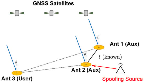
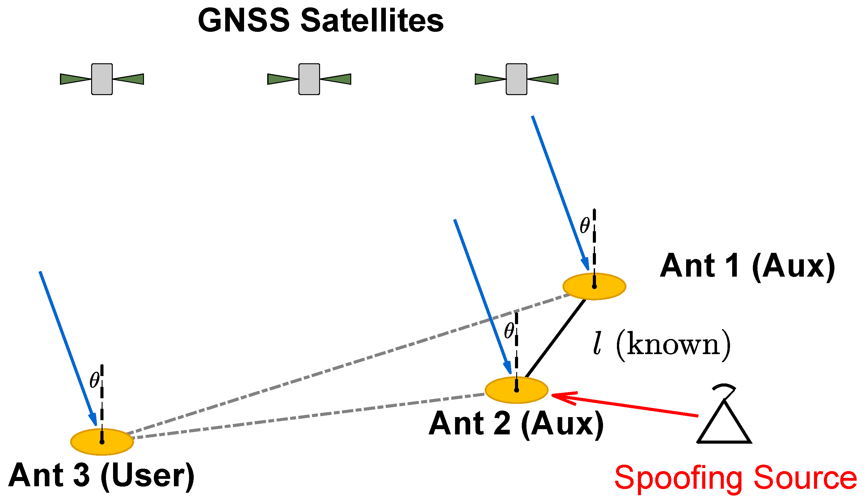
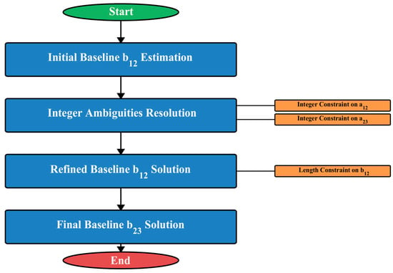
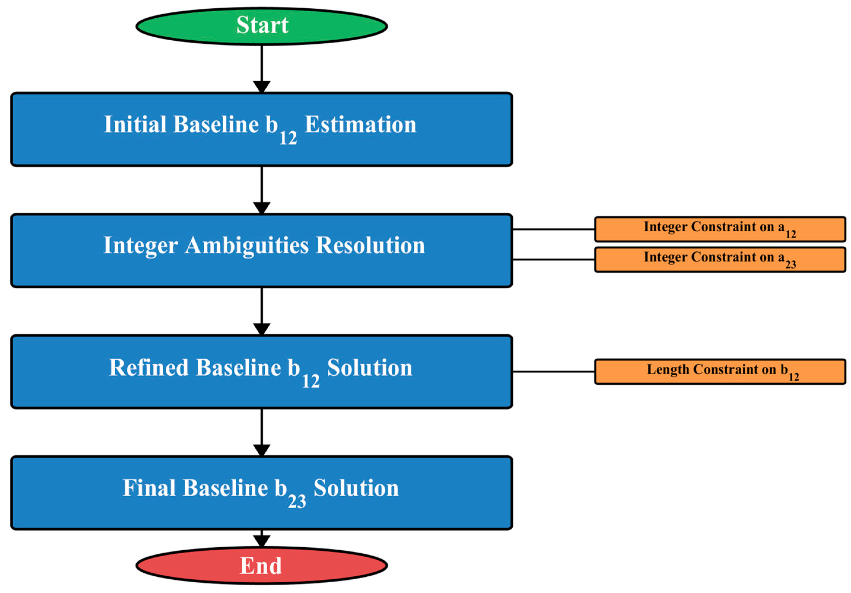
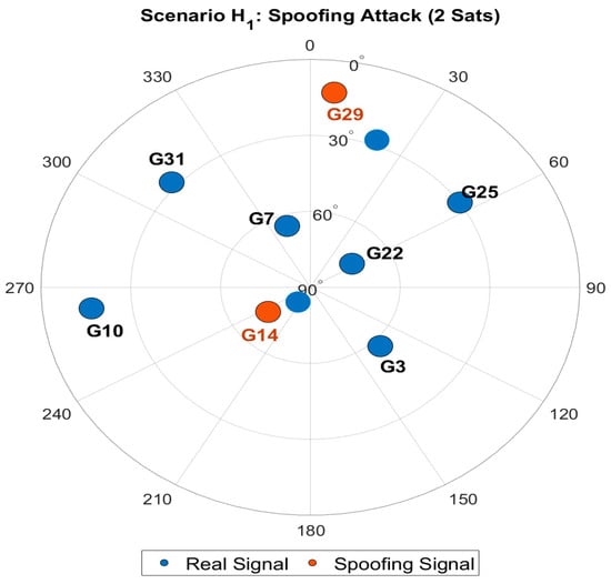
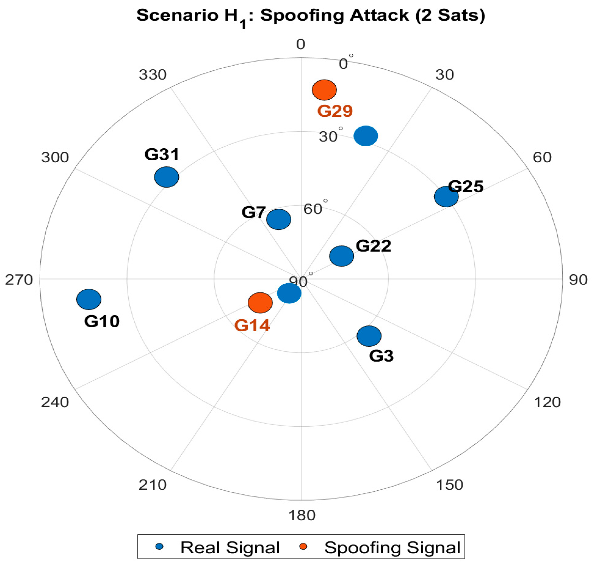
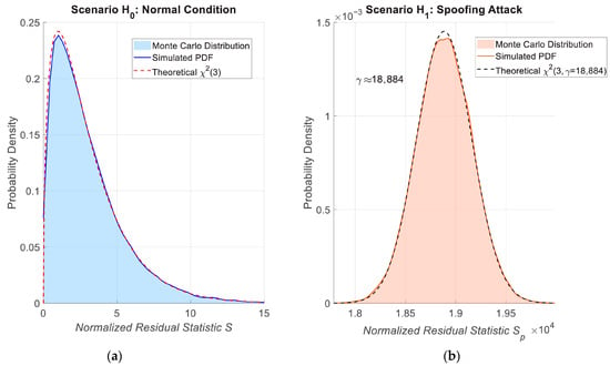
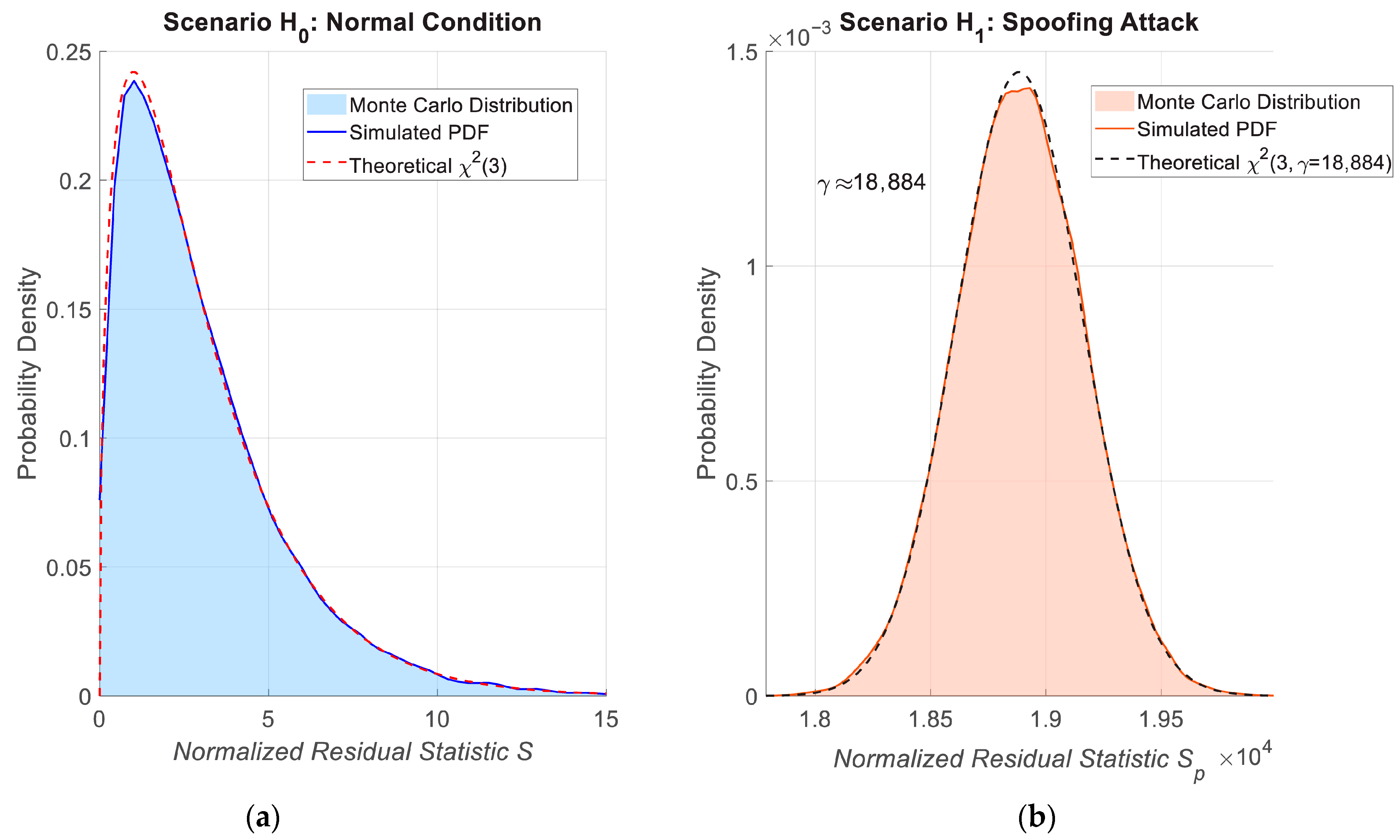
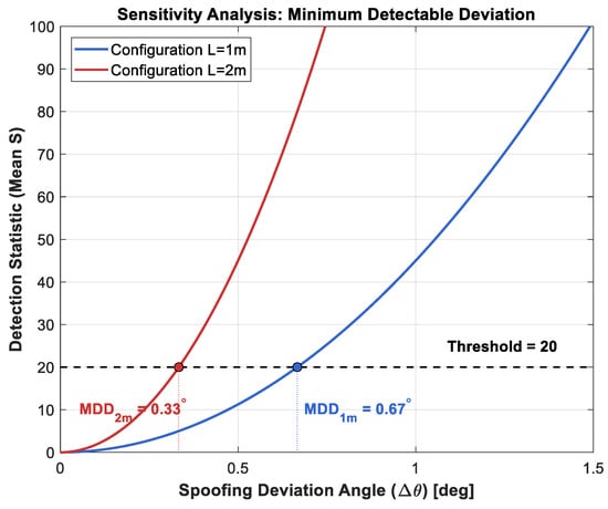
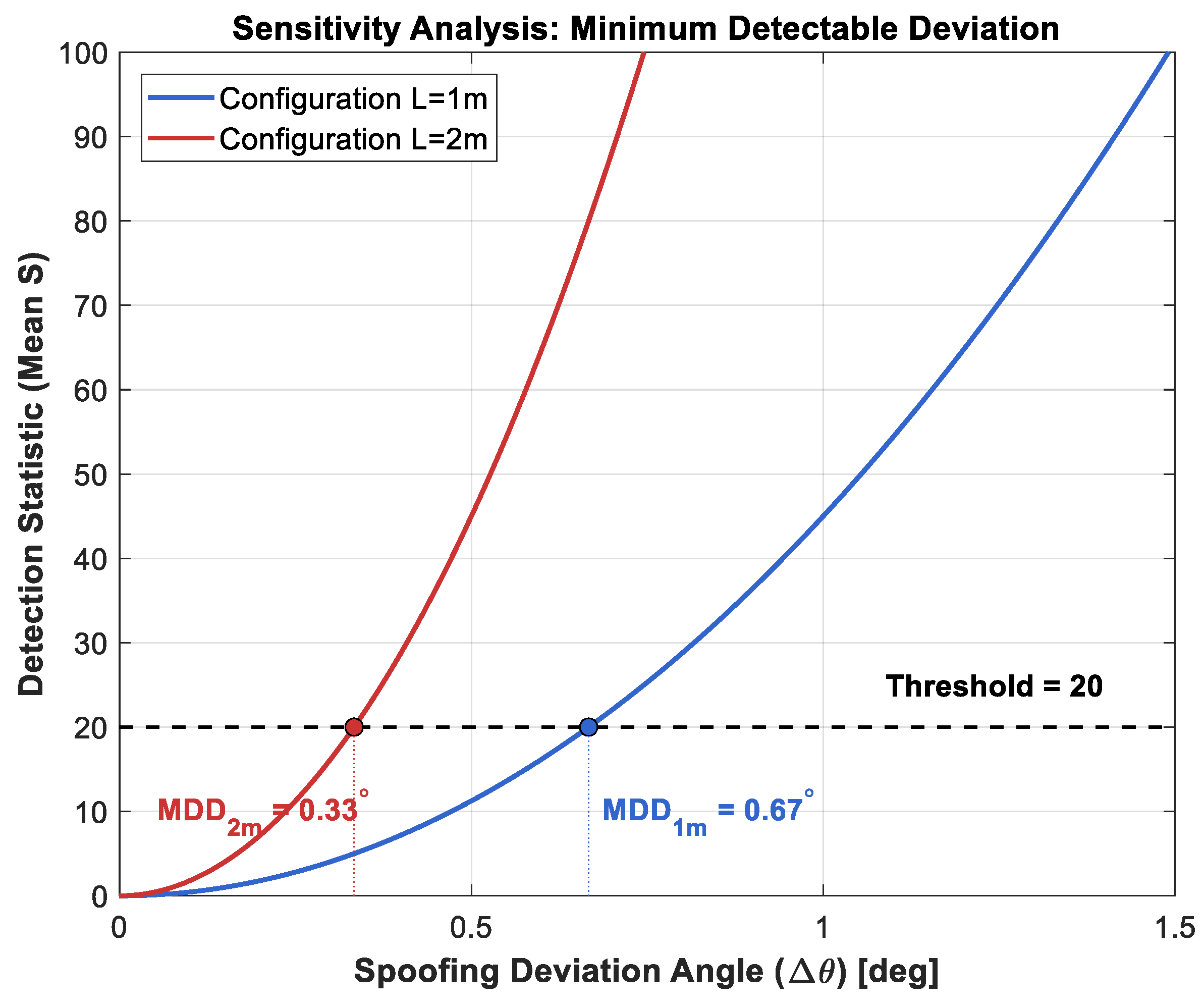
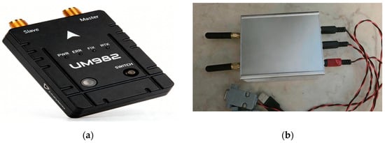
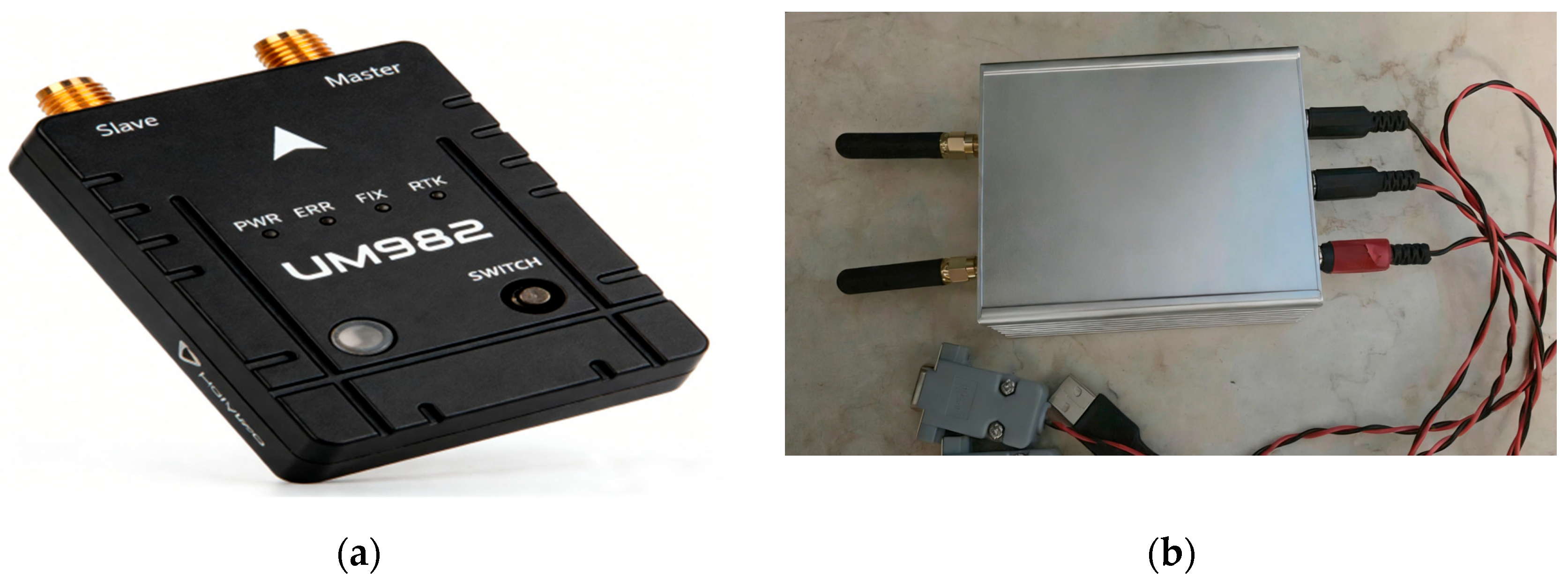
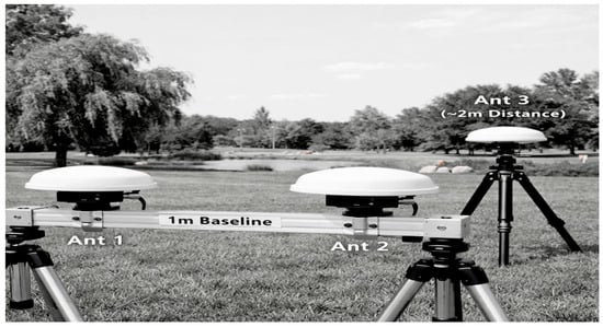
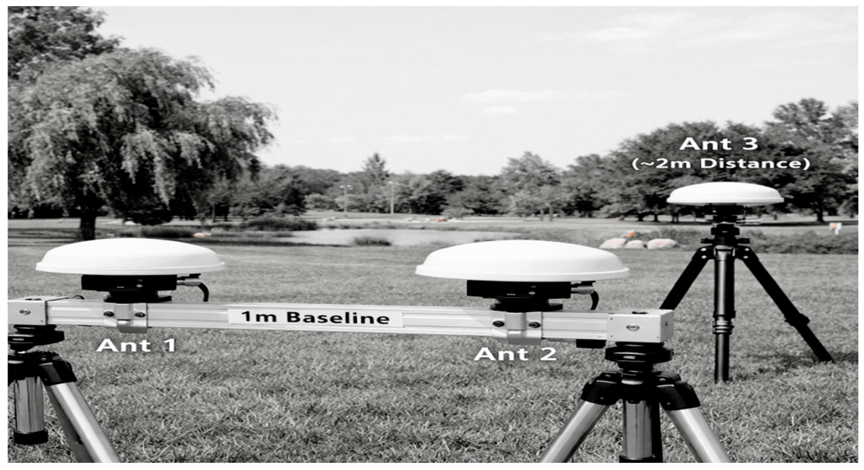
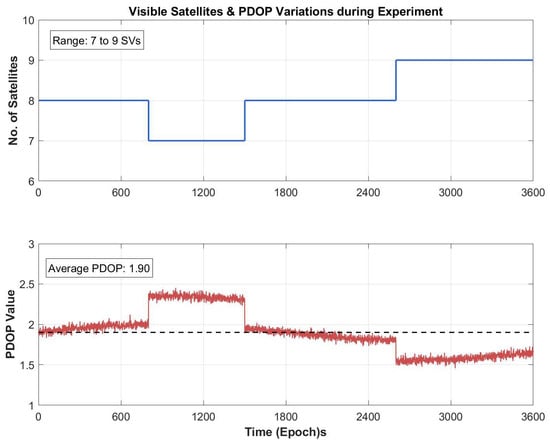
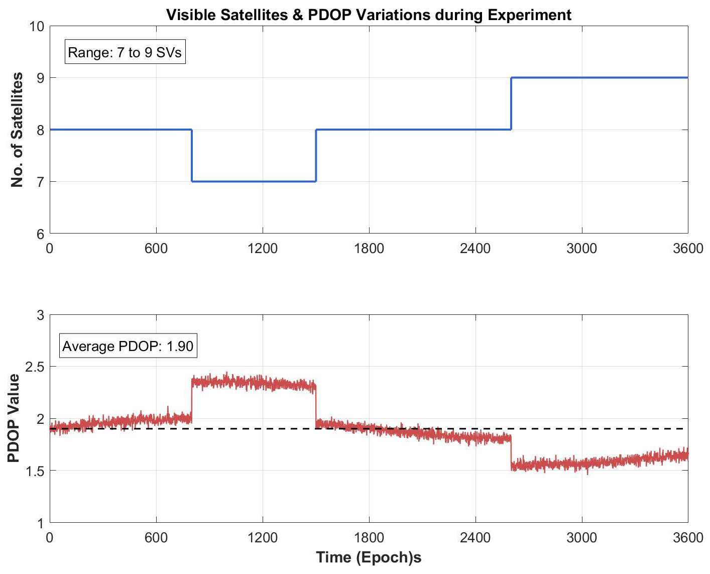
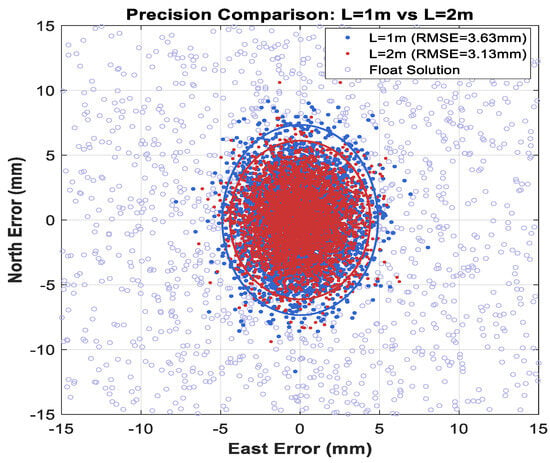
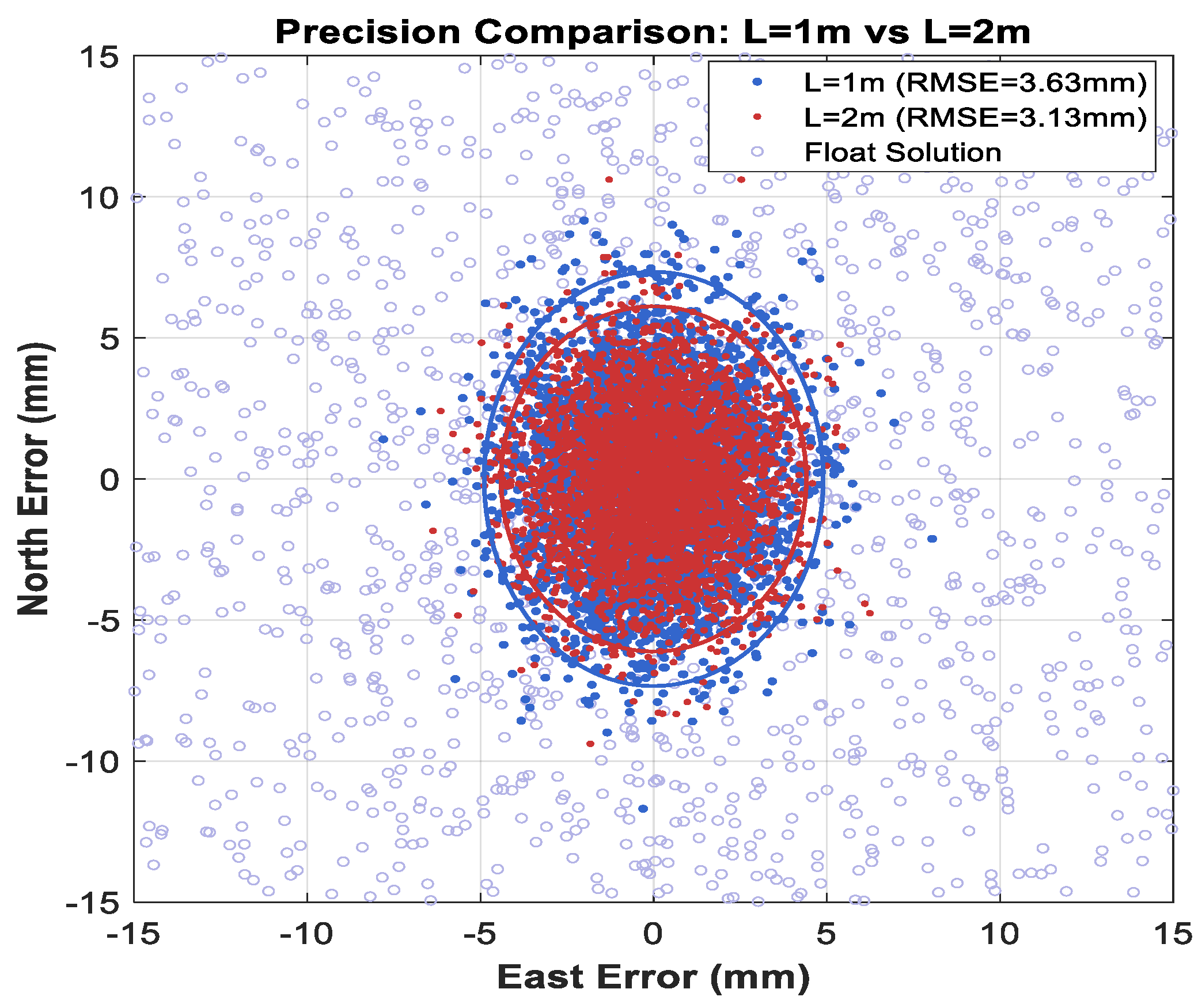
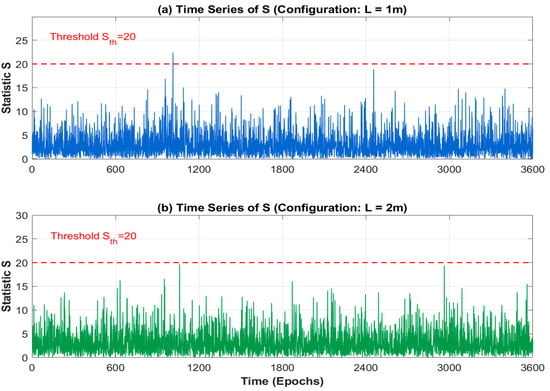
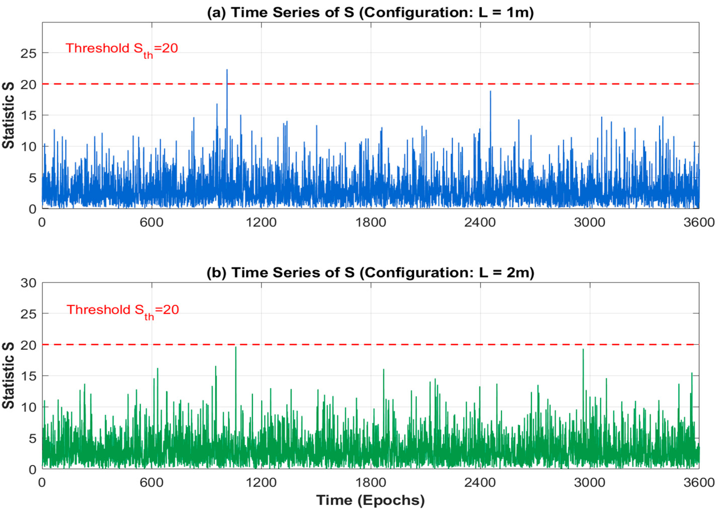
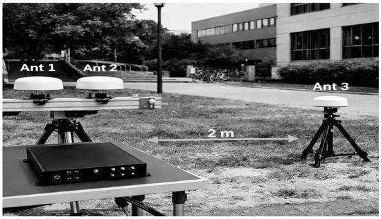
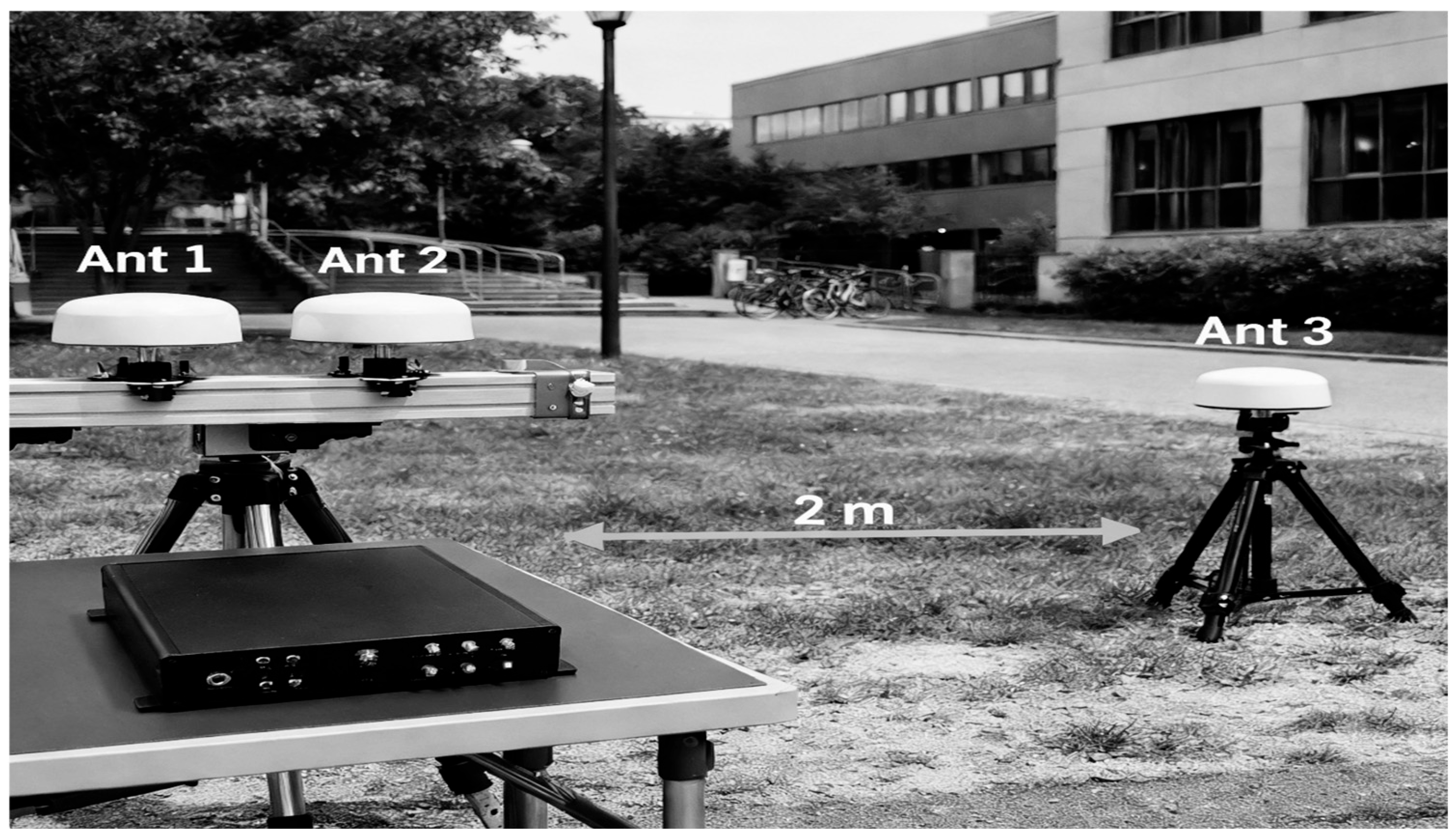
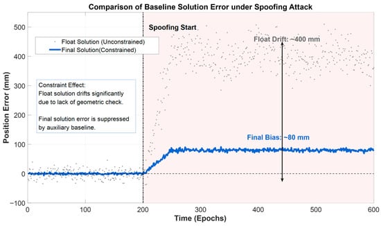
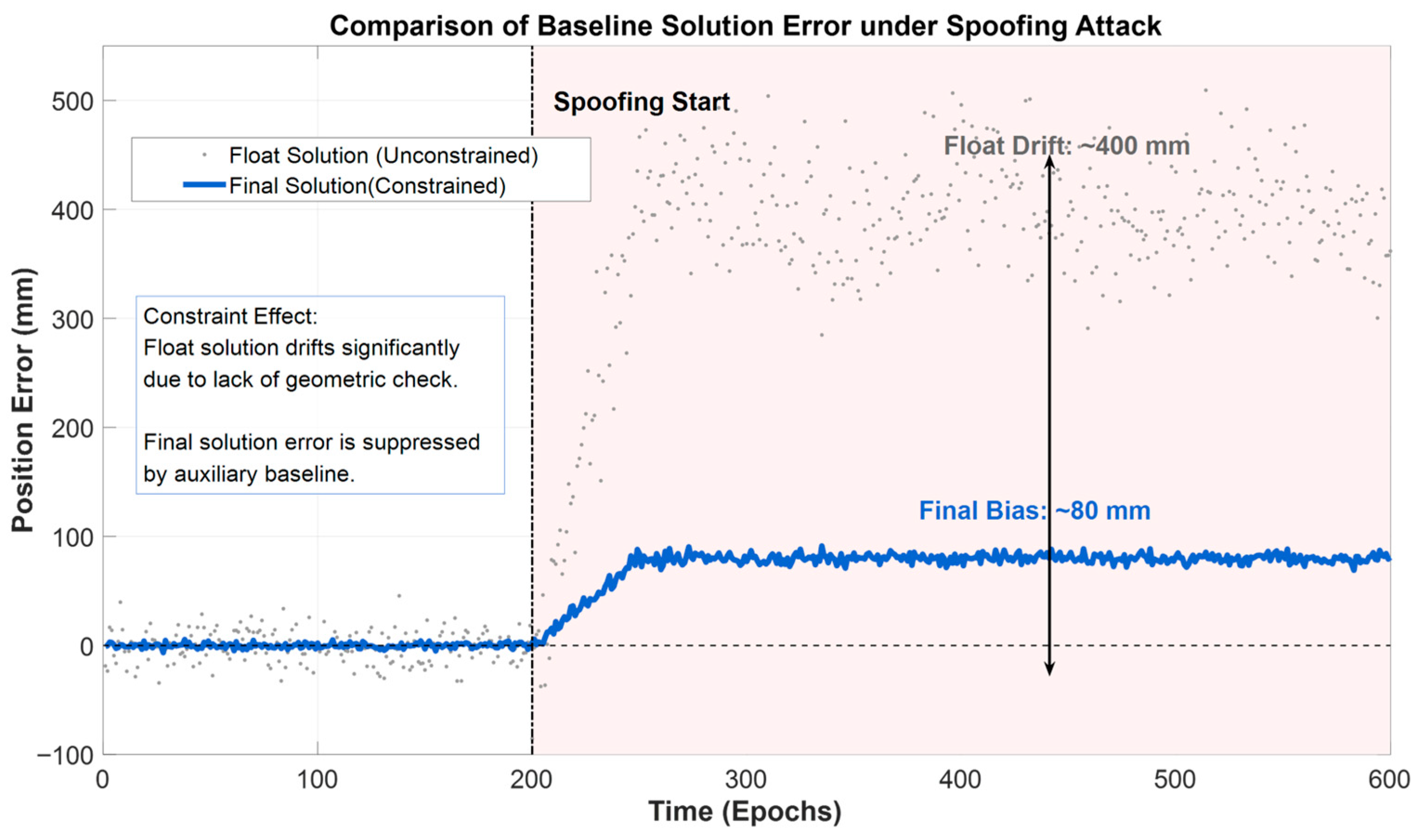
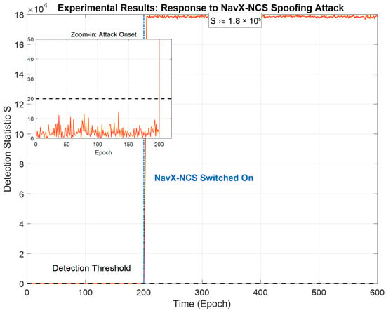
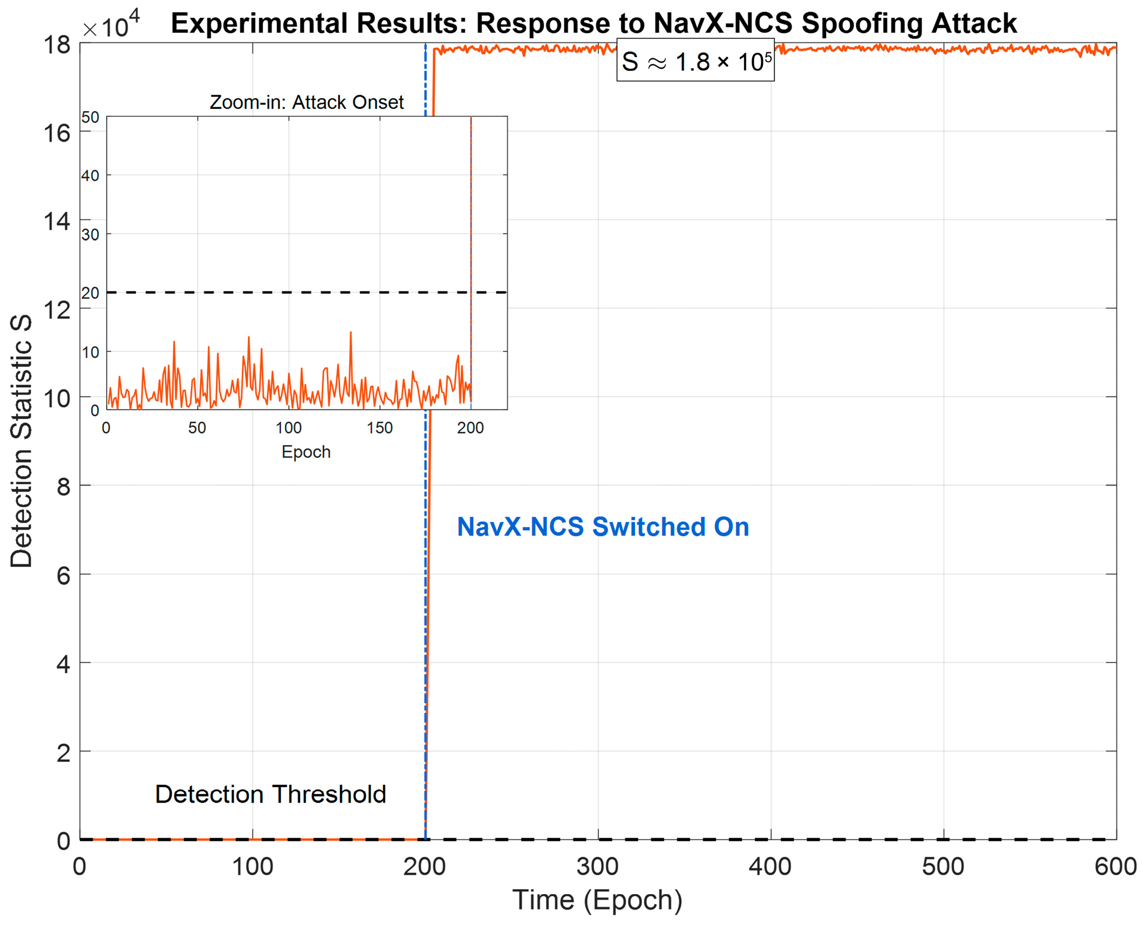
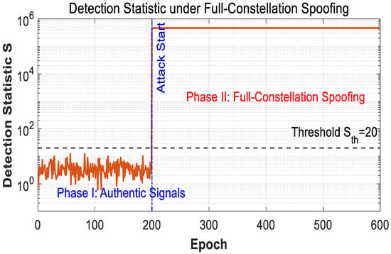
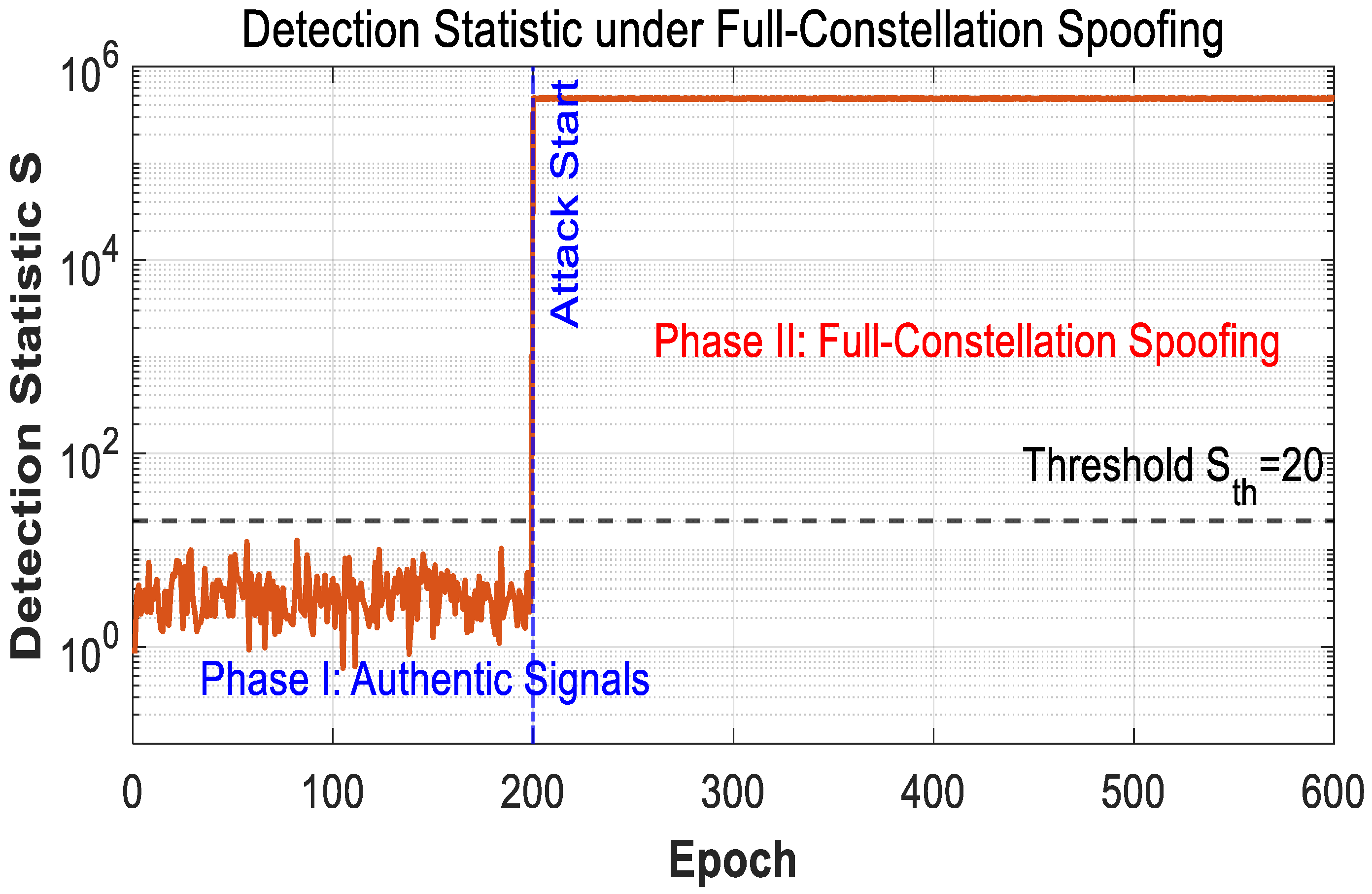

Disclaimer/Publisher’s Note: The statements, opinions and data contained in all publications are solely those of the individual author(s) and contributor(s) and not of MDPI and/or the editor(s). MDPI and/or the editor(s) disclaim responsibility for any injury to people or property resulting from any ideas, methods, instructions or products referred to in the content. |
© 2026 by the authors. Licensee MDPI, Basel, Switzerland. This article is an open access article distributed under the terms and conditions of the Creative Commons Attribution (CC BY) license.