


Abstract
This article proposes a novel predefined-time sliding mode fault-tolerant control method for the attitude tracking of hypersonic vehicles subject to actuator failures and external disturbance. A novel sufficient condition of the Lyapunov function ensuring predefined-time stability and practical predefined-time stability is established, which serves as the theoretical basis for the controller design. In contrast to existing Lyapunov conditions, this formulation provides greater design flexibility. Based on this theoretical foundation and an extended state observer, a predefined-time sliding mode controller is developed. The controller ensures system robustness while enabling an accurate estimate of the settling time upper bound, which is independent of initial conditions. Furthermore, the actual settling time can be tuned via the preset parameters. Finally, the proposed controller is evaluated on a hypersonic vehicle model subject to actuator bias, loss of effectiveness faults, and external disturbance. Numerical simulations demonstrate that the proposed method exhibits superior performance, including faster convergence, lower tracking errors, and enhanced robustness and fault tolerance, compared to an existing predefined-time sliding mode control approach.
1. Introduction
A hypersonic vehicle is a winged or wingless aircraft that flies at velocities above Mach 5. Due to their hypersonic velocity, high maneuverability, and long-range flight performance [1], hypersonic vehicles have received tremendous attention from research communities worldwide. Such vehicles are characterized by strong coupling, significant nonlinearity, and high uncertainty [2], which pose significant challenges to the design of attitude control systems. For long-duration missions, rapid actuator deflections are necessary to execute maneuvers. These demanding performance requirements, combined with the extreme flight conditions, may render hypersonic vehicles more susceptible to actuator failures, such as stuck faults, loss of effectiveness, and hybrid time-varying faults [3], which can lead to performance degradation or catastrophic accidents [4]. To address these challenges, various control methods have been investigated for fault-tolerant control (FTC), such as model predictive control [5], backstepping control [6], fuzzy control [7], and sliding mode control (SMC) [8]. Among them, the SMC method has been widely applied to nonlinear systems due to its robustness against bounded disturbances [9].
Fault-tolerant attitude control for hypersonic vehicles requires quick response capability to ensure precise and safe operation; otherwise, significant losses may result. However, traditional SMC guarantees asymptotic stability, implying that the system converges only as time approaches infinity [10]. Consequently, asymptotic control cannot meet the requirement for rapid response. To address this limitation, finite-time control theory [11] was introduced, which ensures that the system state converges in a finite time. Since then, finite-time control theory has been extensively applied to the design of sliding mode controllers [8,12]. However, a drawback of this approach is that the system’s convergence time depends on its initial state. In practical engineering, where system parameters are often unknown and accurate initial states are difficult to obtain, the convergence time bound estimated via finite-time control can be unreliable. To reduce this dependence on the initial state, Polyakov [13] proposed the fixed-time control method, which guarantees that an upper bound of the convergence time is constant and independent of the initial conditions. Currently, some fixed-time SMC methods have been applied to spacecraft attitude tracking control [14,15]. Simulation results indicate that the system can achieve stability within the pre-calculated convergence time even when the initial state changes. However, fixed-time stability has two main limitations [16]. First, the convergence time bound derived from stability analysis often differs considerably from the actual settling time observed in simulations. Second, as this bound is typically a complex function of system parameters, it is difficult to preset directly.
To overcome the limitations of fixed-time control, Sánchez-Torres et al. [17] introduced the concept of predefined-time stability (PTS), which explicitly establishes a direct relationship between the upper bound of the convergence time and the control parameters. This approach allows the convergence time to be preset precisely via parameter adjustment, thereby circumventing the overestimation issue. Due to this characteristic, predefined-time control has attracted considerable attention in practical engineering applications where high-performance time response is required to meet specific quality or safety standards. For instance, Li Yue [18] developed a predefined-time polynomial-function-based synchronization of chaotic systems via sliding mode control, which allows the synchronization time to be preset offline. Moreover, the ratio between the formation time and the convergence time of sliding mode can be distributed in advance, offering greater flexibility. Similarly, Xue Liu [19] proposed a novel Lyapunov function and a fast terminal sliding mode to achieve predefined-time synchronization for two different multiple-input-multiple-output systems. Focusing on predefined-time synchronization for chaotic systems, Liu Li [20] also proposed a new predefined-time sliding mode control method. Numerical simulations demonstrated advantages in synchronization speed and control precision compared to traditional predefined-time, finite-time, and fixed-time sliding mode control methods. In a different approach, Jin et al. [21] incorporated two time constants into the traditional predefined-time lemma, resulting in improved convergence properties. Based on this modified lemma, they subsequently introduced an improved predefined-time inverse optimal control method for adaptive tracking control of uncertain switched nonlinear systems. Furthermore, Song et al. [22] established a new sufficient condition of the Lyapunov function to guarantee both PTS and practical predefined-time stability (PPTS). Based on this condition, they proposed an enhanced predefined-time control strategy to achieve load tracking and motor synchronization in multimotor servo systems.
In summary, predefined-time theory offers significant advantages for achieving rapid response. However, a primary obstacle in designing a predefined-time stabilizing controller lies in the difficulty of constructing appropriate Lyapunov functions that satisfy the predefined-time stability conditions in a systematic manner [16]. Furthermore, there remains potential for further performance improvement in sliding mode controllers based on this theory. This paper focuses on the attitude tracking control of hypersonic vehicles subject to actuator faults and disturbances, and proposes a novel predefined-time sliding mode controller. The main contributions of this work are summarized as follows:
- A novel sufficient condition for the Lyapunov function is derived to guarantee both PTS and PPTS, leading to a smaller convergence domain. Incorporating more flexibility than those in [20,23,24], this condition contributes to advancing PTS theory.
- Based on the proposed condition, a predefined-time sliding mode control method is developed for the attitude tracking of hypersonic vehicles subject to actuator faults and disturbances. The controller ensures that the tracking error converges to a compact set near the origin during both the reaching and sliding phases. In comparison with the method presented in [20], the proposed strategy provides greater flexibility in adjusting the control performance, and demonstrates improvements in convergence speed, tracking accuracy, and robustness.
The rest of the paper is structured as follows: Section 2 presents the necessary preliminaries, problem formulation, and the novel Lyapunov-based sufficient condition. The design of the predefined-time sliding mode controller is detailed in Section 3. Simulation results are presented and analyzed in Section 4. Finally, conclusions and future work are given in Section 5.
2. Preliminaries and Problem Formulation
2.1. Predefined-Time Stability
This section presents fundamental definitions and lemmas relevant to PTS analysis. Additionally, a novel sufficient condition for the Lyapunov function is established, which ensures PTS in Theorem 1 and PPTS in Theorem 2.
Definition 1
([25]). For a predefined time , the system with initial condition is said to be PTS if its solution satisfies for all .
Lemma 1
([24]). Consider the system . If there exists a Lyapunov function candidate such that
where and are constants. Then, the system is PTS within a predefined time .
Definition 2
([25]). For a predefined time , the system with is said to be PPTS if there exists a positive constant ϵ such that the solution satisfies for all .
Lemma 2
([23]). Consider the system . If there exists a Lyapunov function candidate such that
where , , and are constants. Then, the system is PPTS, and its solutions converge to a compact set within a minimum upper bound of settling time . The compact set is given by
Theorem 1.
Consider the system . If there exists a Lyapunov function candidate such that
where , , , , and are constants. Then, the system is PTS within a predefined time .
Proof of Theorem 1.
From Equation (4), one has
Let be the convergence time for the initial condition , such that . Integrating both sides from to yields
Then
Therefore, according to Definition 1, Equation (4) is PTS within the predefined time . □
Theorem 2.
Consider the system . If there exists a Lyapunov function candidate such that
where , , , , , and are constants. Then, the system is PPTS, and its solutions converge to a compact set within a minimum upper bound of settling time . The compact set is given by
Proof of Theorem 2.
Let , and define two compact sets and . Then, the proof process can be divided into the following two cases:
Case1—if , Equation (8) can be rewritten as
Thus, is strictly monotonically decreasing with respect to t when . Assume that is the moment when V reaches the compact set for the first time, and then . Integrating both sides from to yields
Therefore, for any , the state satisfies .
Case 2: If , then by definition . Furthermore, the analysis in Case 1 demonstrates that once , it remains so for all future time. Hence, the solution remains within .
Combining both cases, it is concluded that the system is PPTS and the system can converge to a bounded set , and the settling time can be bounded by . □
In contrast to Theorem 1, Theorem 2 introduces an extra factor in the settling-time bound. Here is a design parameter, not the final guaranteed convergence time.
The constant in Theorem 2 characterizes the bound of the lumped disturbance. Note that if the lumped disturbance is absent (), the condition for PPTS in Theorem 2 reduces to that for PTS in Theorem 1.
As demonstrated in Theorems 1 and 2, this study introduces additional degrees of freedom through the parameters a, b, and c in the sufficient conditions of Equations (4) and (8), thereby extending the existing PTS theory. Compared with the conditions in [20,23,24], these parameters provide greater flexibility for tuning the control performance and for scaling the difference between the actual settling time and the predefined time.
2.2. Mathematical Model of Hypersonic Vehicle
The attitude tracking problem for a hypersonic vehicle performing bank-to-turn (BTT) maneuvers via aerodynamic control surfaces is considered, as described in [26]. The model incorporates external disturbance and actuator failures. The attitude dynamics are given as
where is the attitude vector (angle of attack, sideslip angle, and bank angle), is the angular rate vector (roll, pitch, and yaw rates), and is the aerodynamic moment vector (roll, pitch, and yaw moments). Assuming the inertia products are negligible, the matrices are respectively defined by
where () denote the moments of inertia. V, , L, Z, m are the velocity, flight path angle, lift, side force, and mass of the vehicle, respectively. The aerodynamic force and moment are expressed as
where D, , , and are drag, atmospheric density, aerodynamic reference area, and aerodynamic reference length of the hypersonic vehicle, respectively. is the control command signal. , , and are aerodynamic force coefficients. , , and are aerodynamic moment coefficients. In this study, four control surface deflections are considered: (left elevon, upper rudder, right elevon, lower rudder). The allocation matrix satisfies .
In addition, physical constraints on actuator deflection amplitude always exist. The amplitude saturation of the deflection of the i-th control surface is modeled as [27]
where denotes the saturation limit for the i-th control surface deflections. is a small positive value.
Under normal conditions, expected maneuvers can be performed by generating appropriate aerodynamic forces and moments. However, if actuator failures occur, maneuvers may no longer be maintained by the nominal controller [28]. Therefore, this paper considers two types of actuator faults for FTC: loss of effectiveness and actuator bias.
Considering actuator faults, the relationship between the control surface deflections and the control surface signals is modeled as
where and denote the effectiveness of actuators and the actuator bias, respectively. Specifically, the following fault modes are considered for each control surface:
- No failure: ,
- Loss of effectiveness: ,
- Actuator bias: ,
It is assumed that the actuators retain sufficient control moments to stabilize the system despite the considered faults. Cases involving deficient control capability are beyond the scope of this study.
By incorporating the actuator fault model (Equation (20)), saturation model (Equation (19)), and external disturbance, the control-oriented nonlinear dynamic model is formulated as follows:
where denotes the lumped disturbance arising from actuator faults, saturation, and external disturbance. The matrices and are defined as
The lumped disturbance d can be expressed as
where represents external disturbance.
Assumption 1.
To establish explicit tracking error bounds in Section 3, the following assumptions are made on system uncertainties and faults:
- 1.
- External disturbance bound:
- 2.
- Actuator fault bounds: ,
- 3.
- Saturation-induced error bound:
where are constants.
Based on Assumption 1, the lumped disturbance d in Equation (22) satisfies .
This article aims to develop a predefined-time fault-tolerant tracking control strategy, such that the closed-loop system is PPTS, ensuring that the tracking error converges to a small neighborhood of the origin.
3. New Predefined-Time Sliding Mode Control Method
This section first employs an extended state observer (ESO) to estimate and compensate for the lumped disturbance. Subsequently, a new predefined-time sliding mode control strategy is developed for the fault-tolerant attitude tracking of hypersonic vehicles.
3.1. Extended State Observer Design
The ESO is designed to estimate the lumped disturbance d, thereby enabling feedforward compensation. This compensation mitigates the adverse effect of the lumped disturbance on the sliding mode controller, reduces control signal chattering, and enhances overall system robustness. By treating the lumped disturbance as an extended state, Equation (22) can be rewritten as
Based on Equation (26), a second-order ESO is employed and given as follows:
where and are the estimated values of the state and the lumped disturbance d. and are positive observer gains. The convergence analysis of such an ESO can be found in [29].
Using the bandwidth-based configuration method [30], consider the ESO (Equation (27)) with gains selected as
where is the observer bandwidth. Let denote the estimation error, and assume that there exists a constant such that . If the initial condition is set as , , then the following properties hold [31]:
- Exponential convergence: There exists a constant independent of such that
- Convergence time: For any , the estimation error satisfies for all , where
- Error bound: As , the disturbance estimation error is uniformly bounded by
A higher observer bandwidth accelerates convergence and reduces steady-state estimation errors, but amplifies sensitivity to measurement noise; conversely, a lower bandwidth enhances noise attenuation at the cost of larger estimation lag, which may degrade transient performance. Given appropriately chosen bandwidth, the estimates and converge to their respective true values.
3.2. Predefined-Time Sliding Mode Controller Design
To achieve predefined-time convergence in both the reaching and sliding phases, a dual-loop control structure is adopted. An inner-loop controller is designed for Equation (22) to track the angular rate command . An outer-loop controller is in turn designed for Equation (21) to track the attitude command and generate . Define the tracking error as and .
For the inner-loop, the sliding surface is designed as
where , , , , and are design parameters.
According to the principle of sliding mode control [32], when the system operates the sliding phase, i.e., and , it can be obtained
The reaching law for the inner-loop controller is formulated as
where , , , , , and .
By compensating for the lumped disturbance d with and substituting the reaching law into the expression for , the inner-loop controller is derived as
Theorem 3.
For Equation (22), the predefined-time sliding mode controller (Equation (32)) guarantees that, during the reaching phase, the sliding mode variable converges to a compact set around the origin within a settling time bounded by . In the subsequent sliding phase, the tracking error converges to a neighborhood of the origin within a settling time bounded by . The total settling time is bounded by .
Proof of Theorem 3.
For the reaching phase, construct the Lyapunov function by
Taking the derivative of Equation (33)
Let denote estimation error of the lumped disturbance. Then, substituting control law (Equation (32)) yields
where . Inequality (35) satisfies the practical predefined-time stability condition of Theorem 2. Therefore, converges to the set
within a settling time bounded by during the reaching phase.
When the system operates in the sliding mode (), are governed by
where represents a bounded perturbation term satisfying , with defined in Equation (36).
For the sliding phase, a Lyapunov function is constructed as
Taking the derivative of Equation (38)
where . By applying Theorem 2, converges to a compact set
within a settling time bounded by during the sliding phase.
For the outer-loop, a new sliding surface is similarly designed as
where , , , , and are design parameters.
When the system operates the sliding phase, i.e., and , it can be obtained
To achieve both PPTS and robustness, the reaching law is designed as
where , , , , and .
Theorem 4.
For Equation (21), the sliding mode controller (Equation (45)) guarantees that, during the reaching phase, the sliding variables converge to a compact set around the origin within a settling time bounded by . In the subsequent sliding phase, the tracking error converges to a neighborhood of the origin within a settling time bounded by . The total settling time is bounded by .
The proof of Theorem 4 follows a similar procedure and is therefore omitted.
Based on the structure of Equations (32) and (45), the terms involving and dominate when the state is far from equilibrium, while the term involving becomes dominant near equilibrium. , , and provide more degrees of freedom for the design of the controller. Furthermore, the parameter is the primary factor determining the convergence speed; smaller values lead to faster convergence but can result in a larger ultimate bound, increased chattering, and larger overshoot. A trade-off can be achieved by adjusting , , and . The influence of each parameter on control performance is discussed in Section 4. Compared to traditional FTC, the proposed scheme allows the upper bound of settling time to be prescribed in advance, offering a practical advantage.
4. Simulation Results and Discussion
In this section, numerical simulations are conducted on MATLAB (R2020b)/SIMULINK using the Runge-Kutta integral method with a fixed step size of 0.01 s. The hardware consists of an Intel Core i7-8700 CPU @ 3.20GHz with 16.0 GB RAM, under the Windows 10 operating system. The vehicle model from [26] is adopted for all simulations. Specifically, the mass, reference area, reference length, and the moments of inertia are , , , , , and , respectively. The allocation matrix and nominal parameters of the aerodynamic force and moment coefficients shown in Equations (17) and (18) are denoted as
The saturation limit for each control surface deflection is . The desired attitude commands are constant: . All simulation experiments use the initial flight conditions shown in Table 1.
Table 1.
Initial flight conditions of the hypersonic vehicle.
To facilitate a quantitative comparison of control performance, the following performance indices are adopted:
- Integral of absolute error (IAE):where is the stop time of the simulation.
- Integral of time-weighted absolute error (ITAE):
- Settling time (): The time required for the tracking error to enter and remain within the band .
- Peak control surface deflection (): The maximum absolute value among all control surface deflections over the entire simulation horizon, i.e.,where denotes the i-th control surface deflection.
- Control energy integral ():
- Average steady-state total variation per second ():where is the maximum settling time among all three attitude channels. This index quantifies the overall chattering of the control surface deflections during the steady-state phase.
4.1. Comparative Simulations
The effectiveness and advantages of the proposed controller are validated through comparison with the predefined-time control strategy presented in [20].
The inner-loop controller, with its sliding surface and control law defined in Equations (58) and (59), is given by
where and .
Similarly, the outer-loop controller is designed as
where , , , , , , and .
To ensure a fair comparison, parameters corresponding to similar terms (e.g., those with the same power) are set to identical values wherever possible. The parameters of two controllers are listed in Table 2. All parameters are tuned to achieve satisfactory performance for each controller.
Table 2.
Control law parameters.
Furthermore, the parameters of the ESO and saturation function for both methods are fixed at , , and across all simulations.
The following subsections provide three sets of comparative simulations to verify the effectiveness and superiority of the proposed method.
4.1.1. Verification Under Nominal Condition
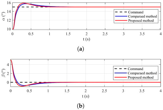
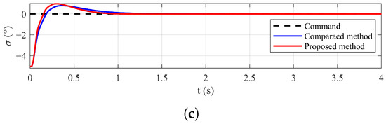
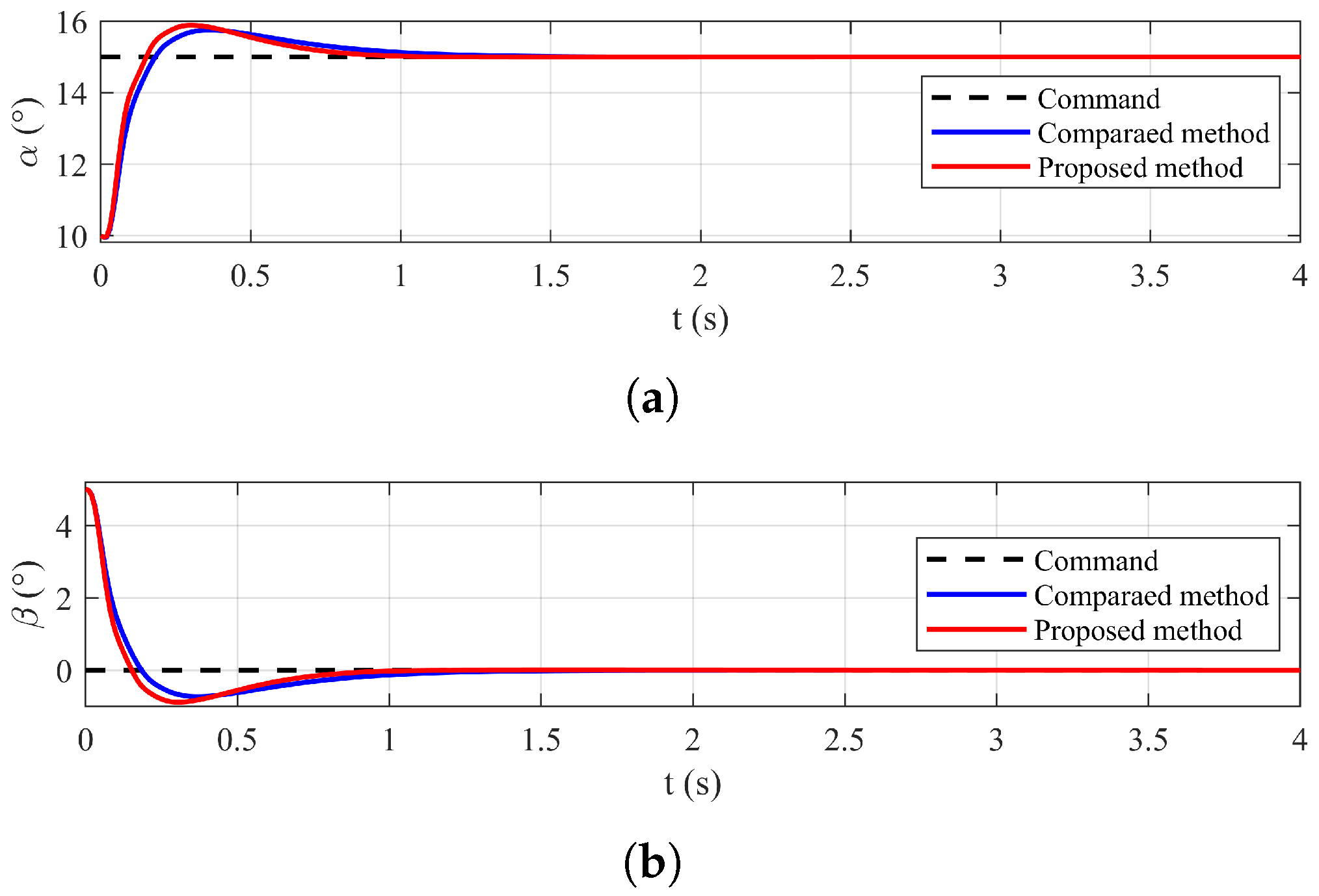
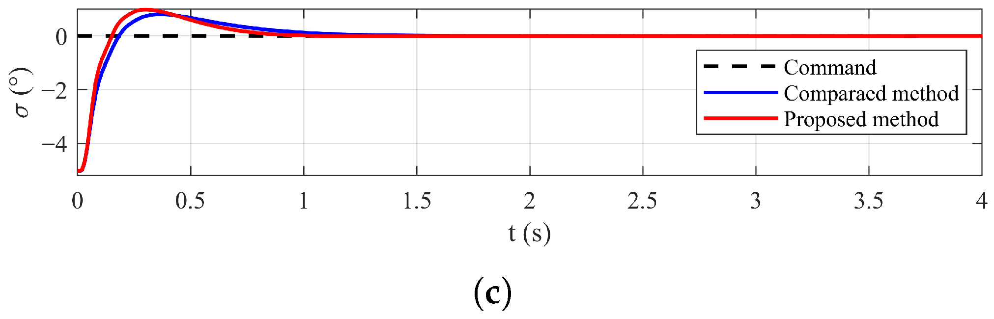
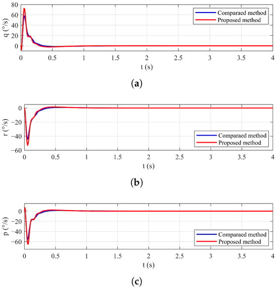
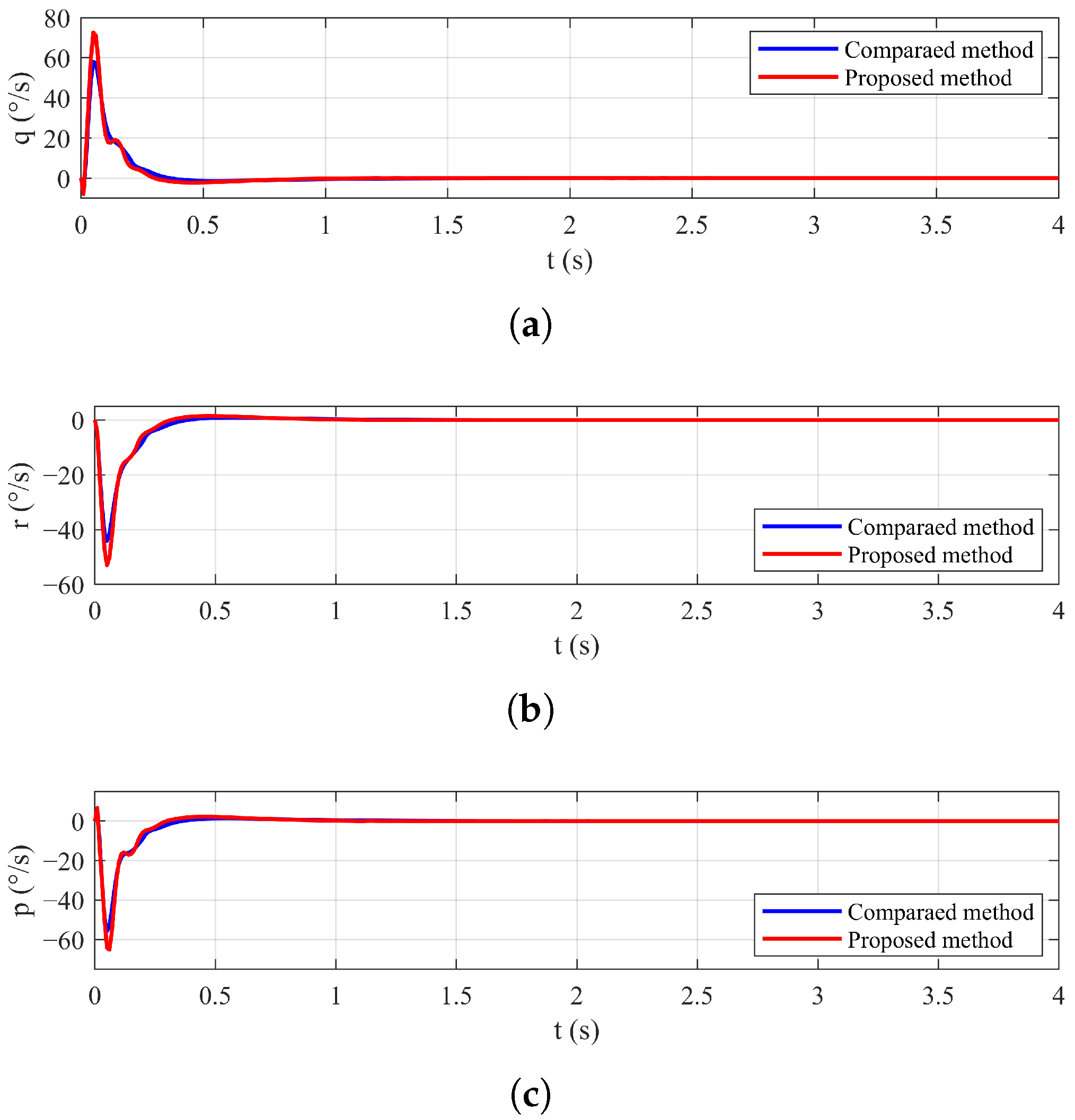
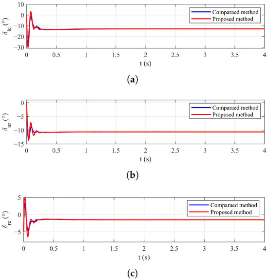
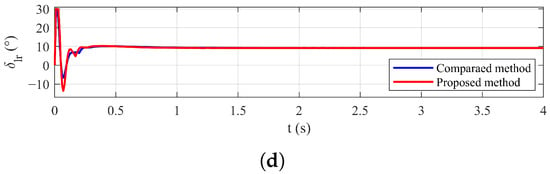
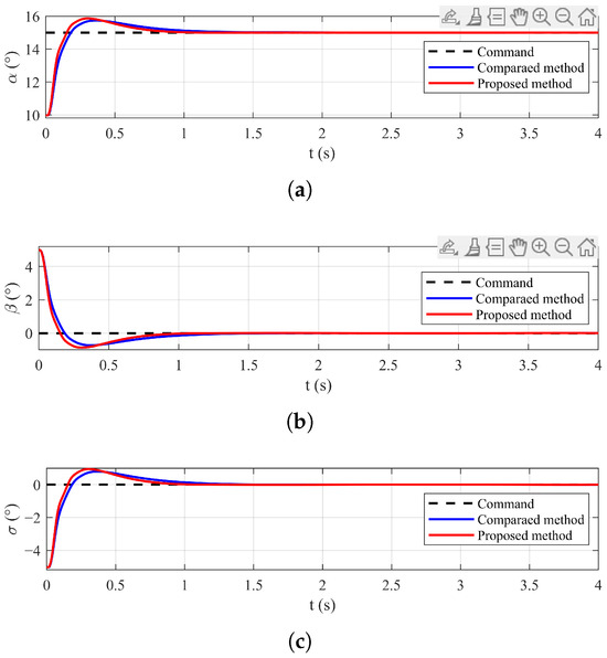
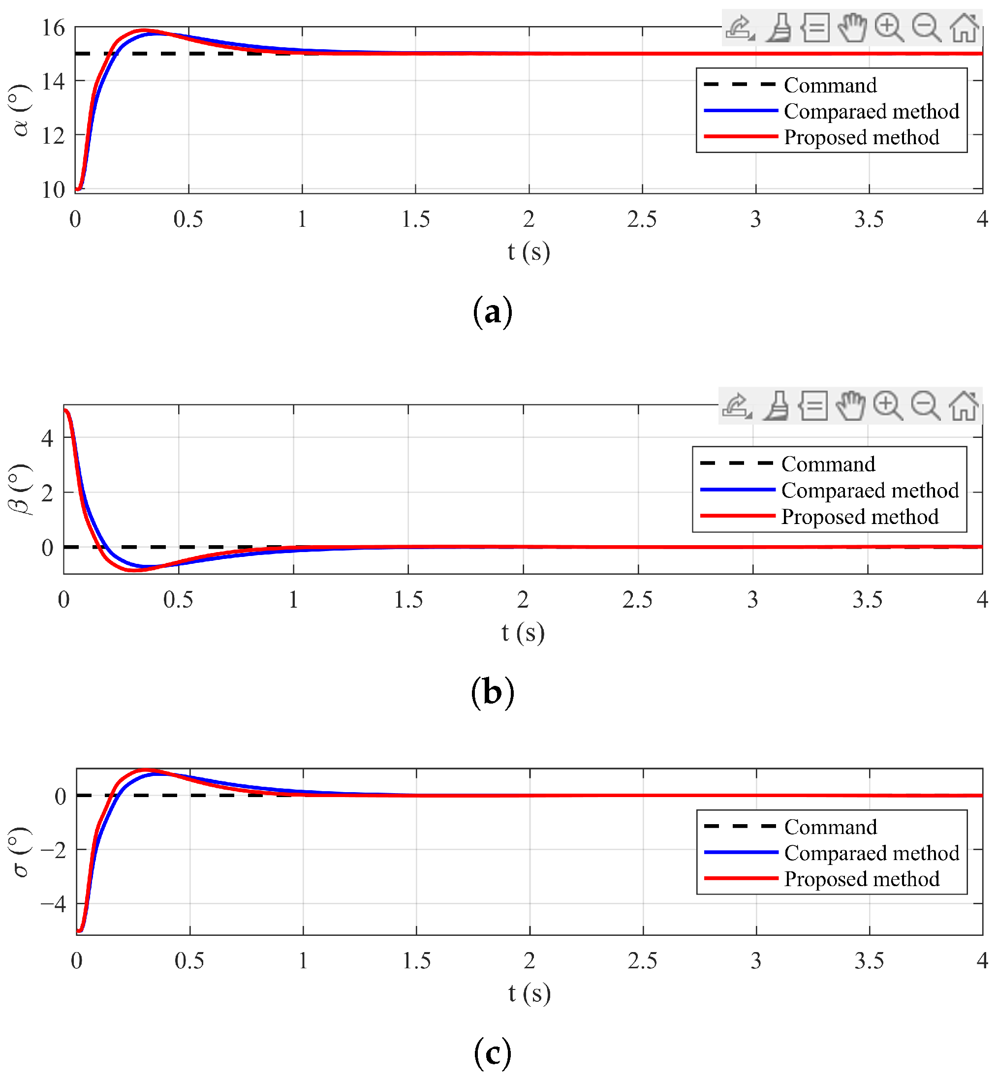
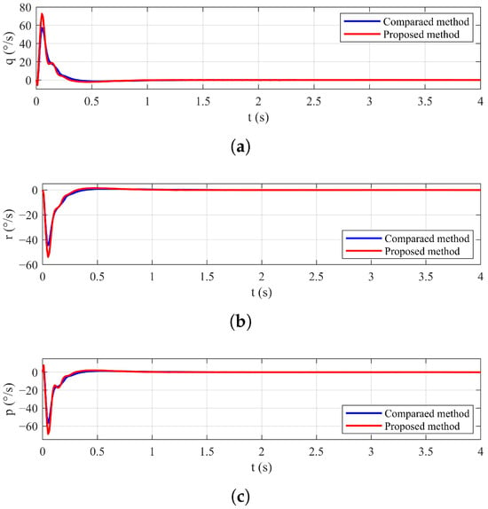
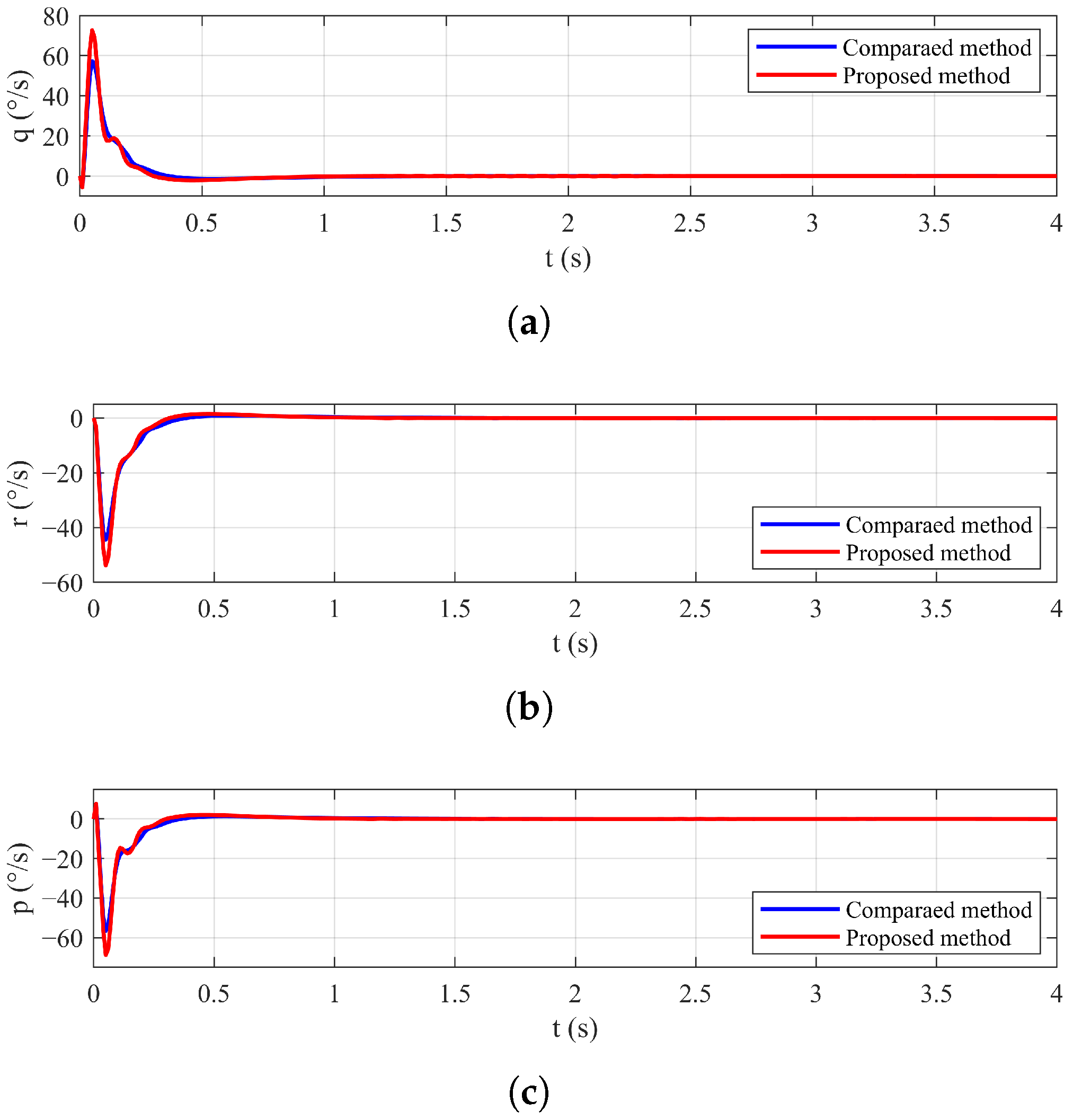
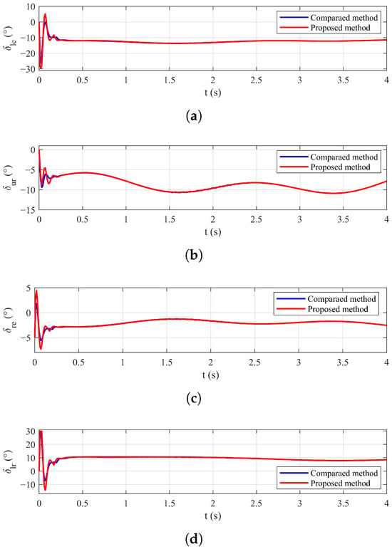
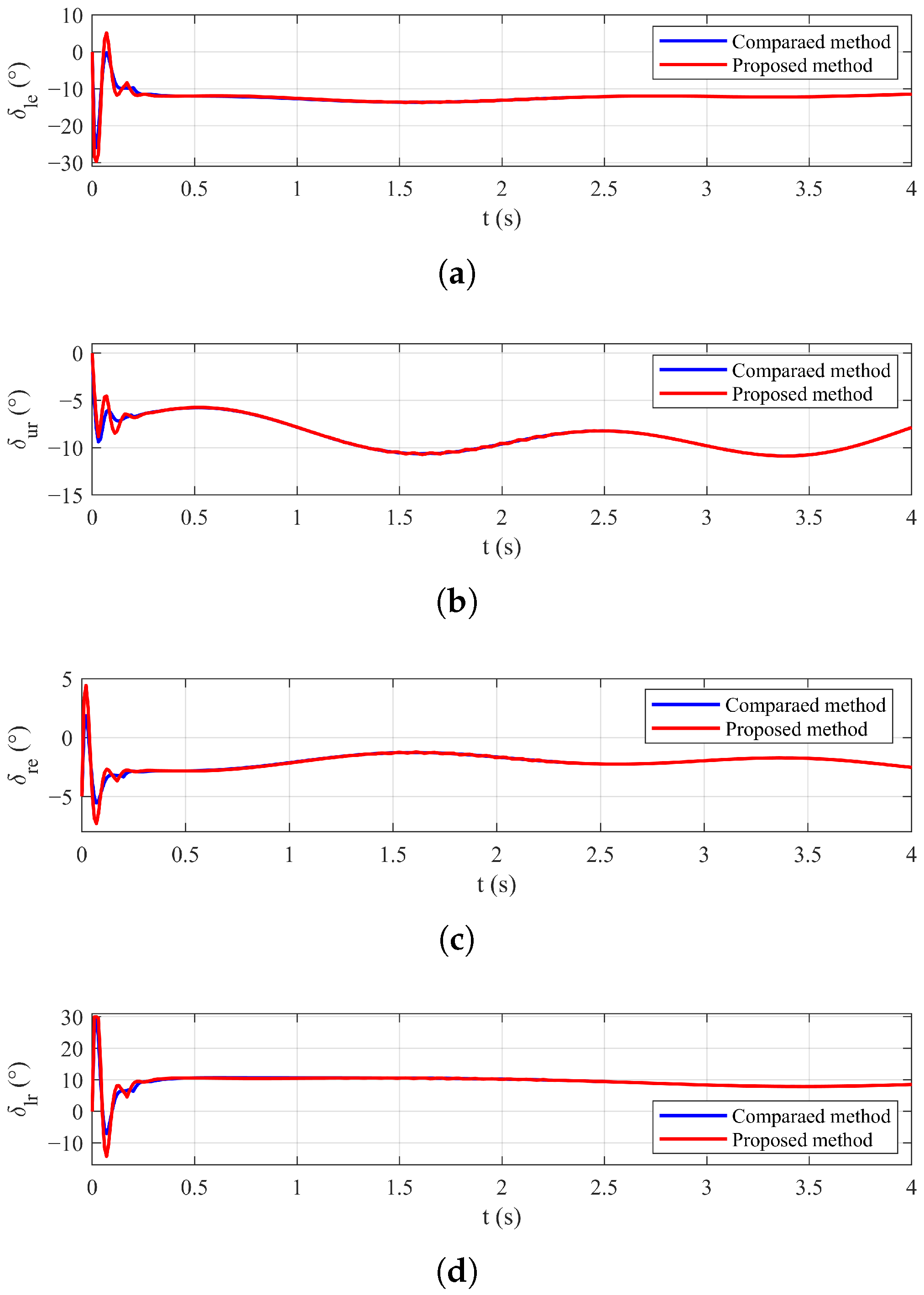
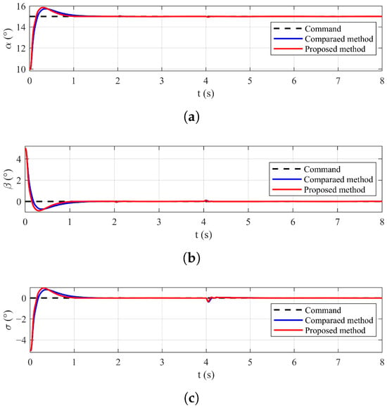
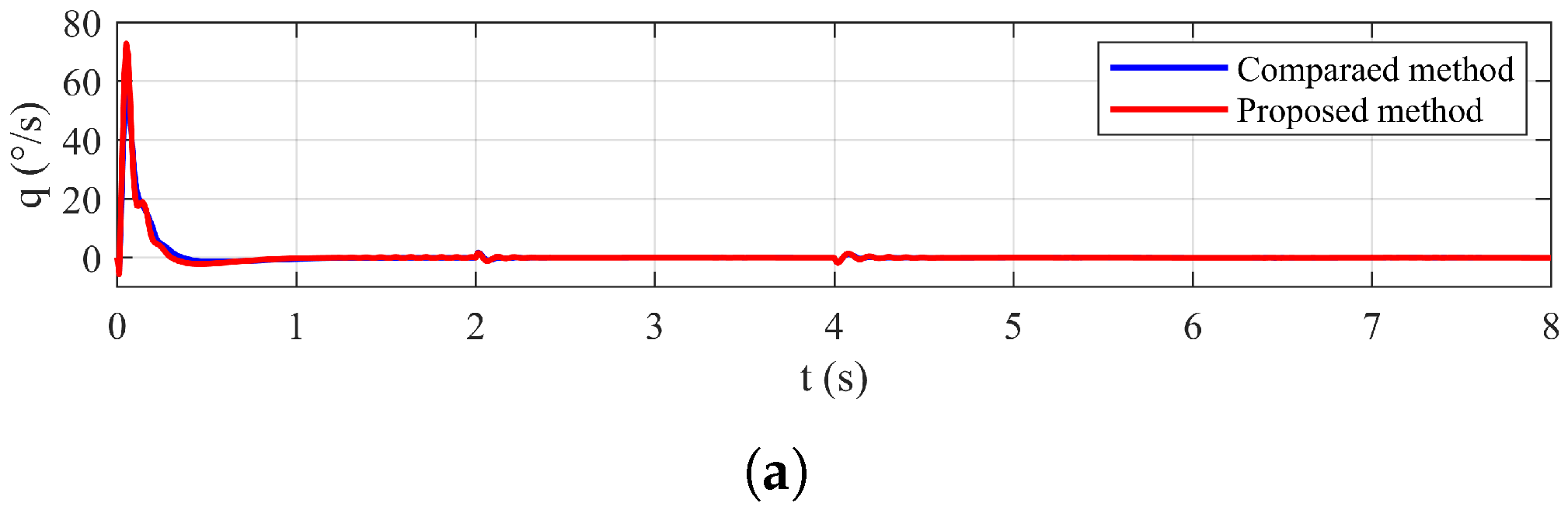
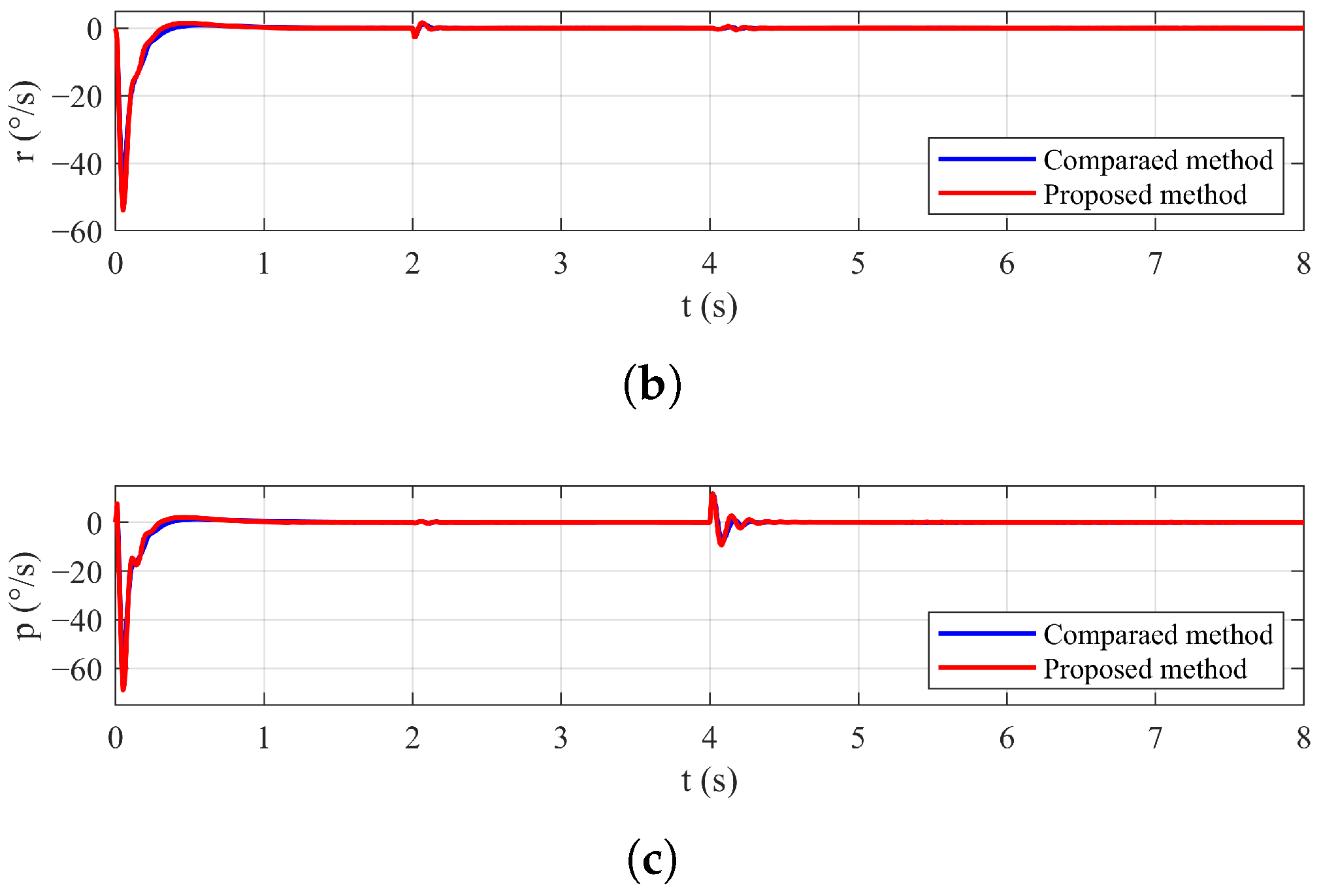
The first set of simulations is conducted under the nominal condition. Figure 1, Figure 2 and Figure 3 present the results of the attitude angle responses, attitude angular rates, and control surface deflections, respectively, for all three channels. For both controllers, the attitude angles achieve effective tracking of the desired attitude commands. Furthermore, Table 3 presents the performance indexes of two methods. These results demonstrate that the proposed method achieves better tracking accuracy, faster convergence, and reduced chattering compared to the benchmark method, indicating the overall superior performance. This performance improvement is achieved at the cost of a slightly higher control energy integral, while the control surface deflections for both methods remain within the saturation limits.
Figure 1.
Attitude angle responses under the nominal condition: (a) Angle of attack response. (b) Sideslip angle response. (c) Bank angle response.
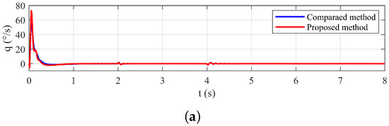
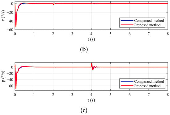
Figure 2.
Attitude angular rates responses under the nominal condition: (a) Pitch rate response. (b) Yaw rate response. (c) Roll rate response.
Figure 3.
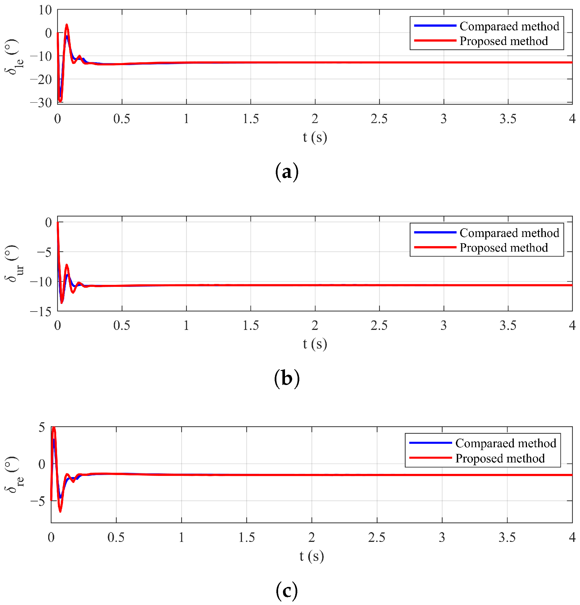
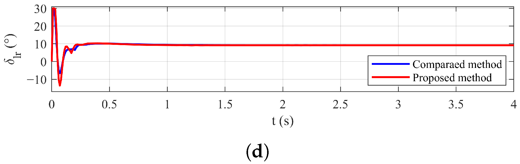
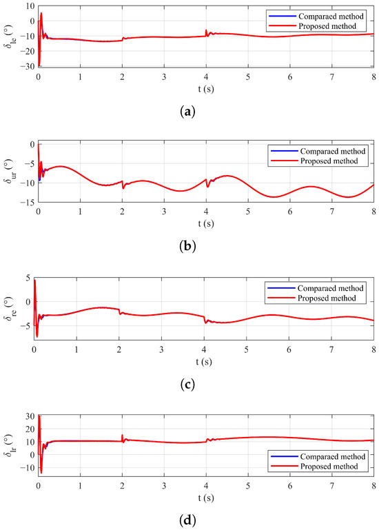
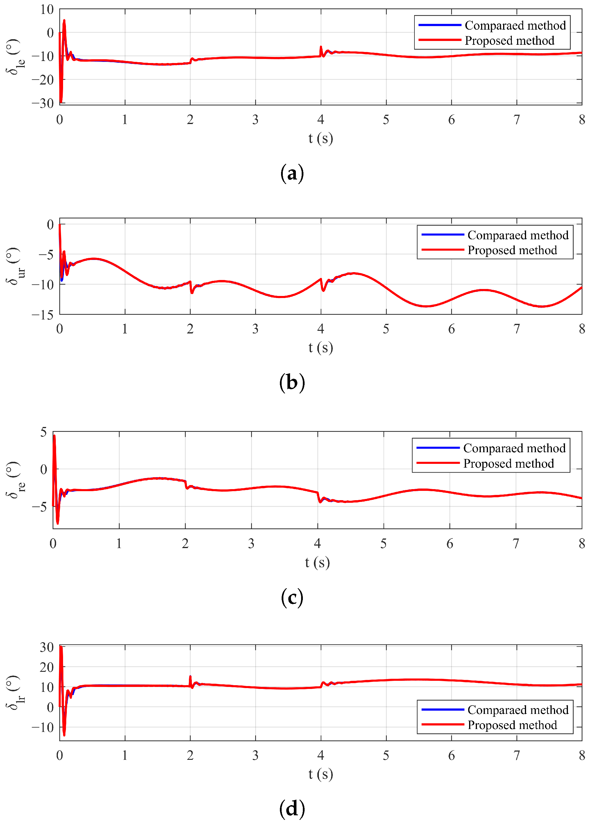
Control surface deflections under the nominal condition: (a) deflection. (b) deflection. (c) deflection. (d) deflection.
Table 3.
Performance indexes under the nominal condition.
4.1.2. Verification Under Disturbance
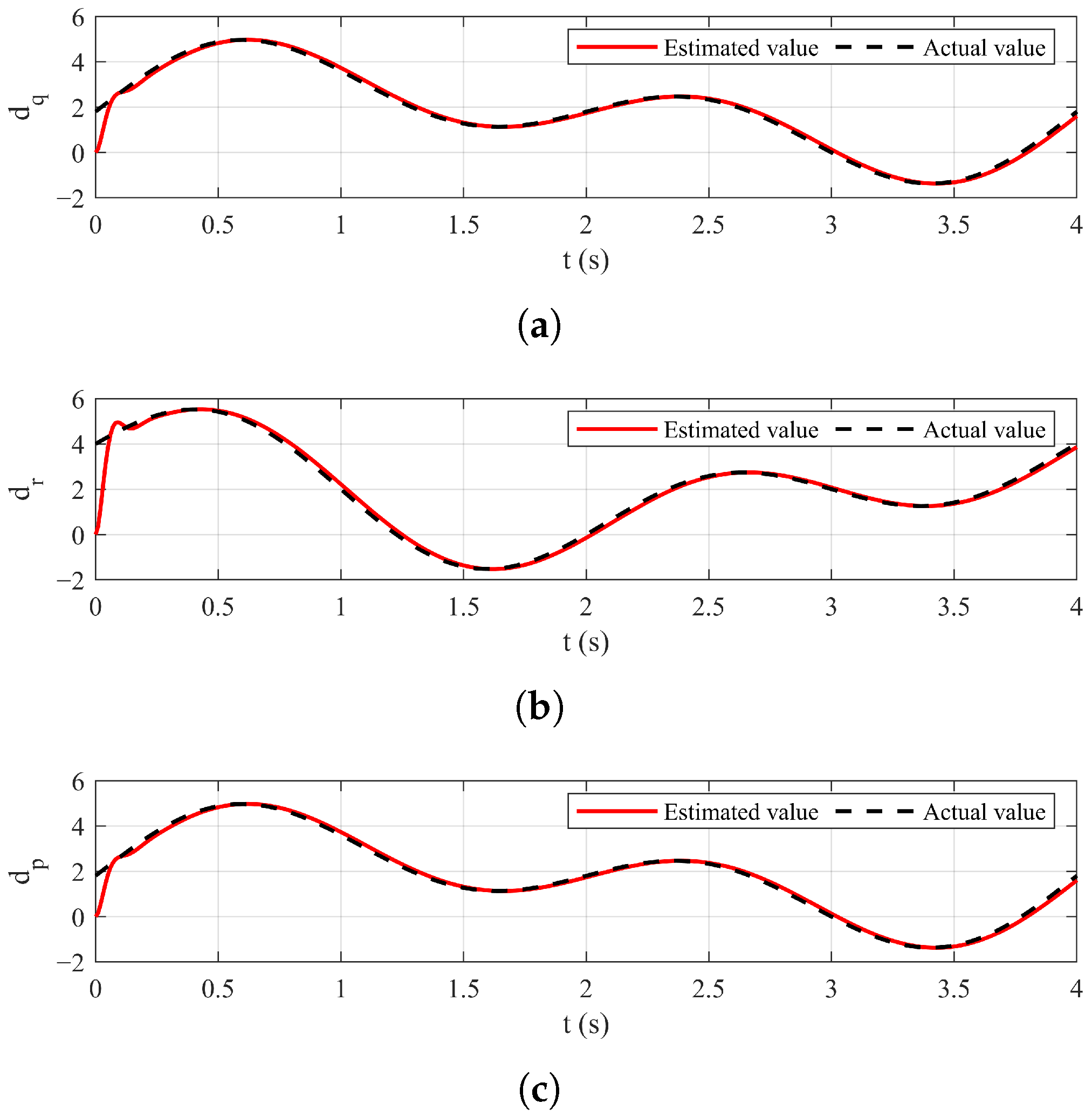
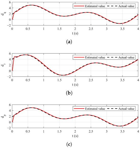
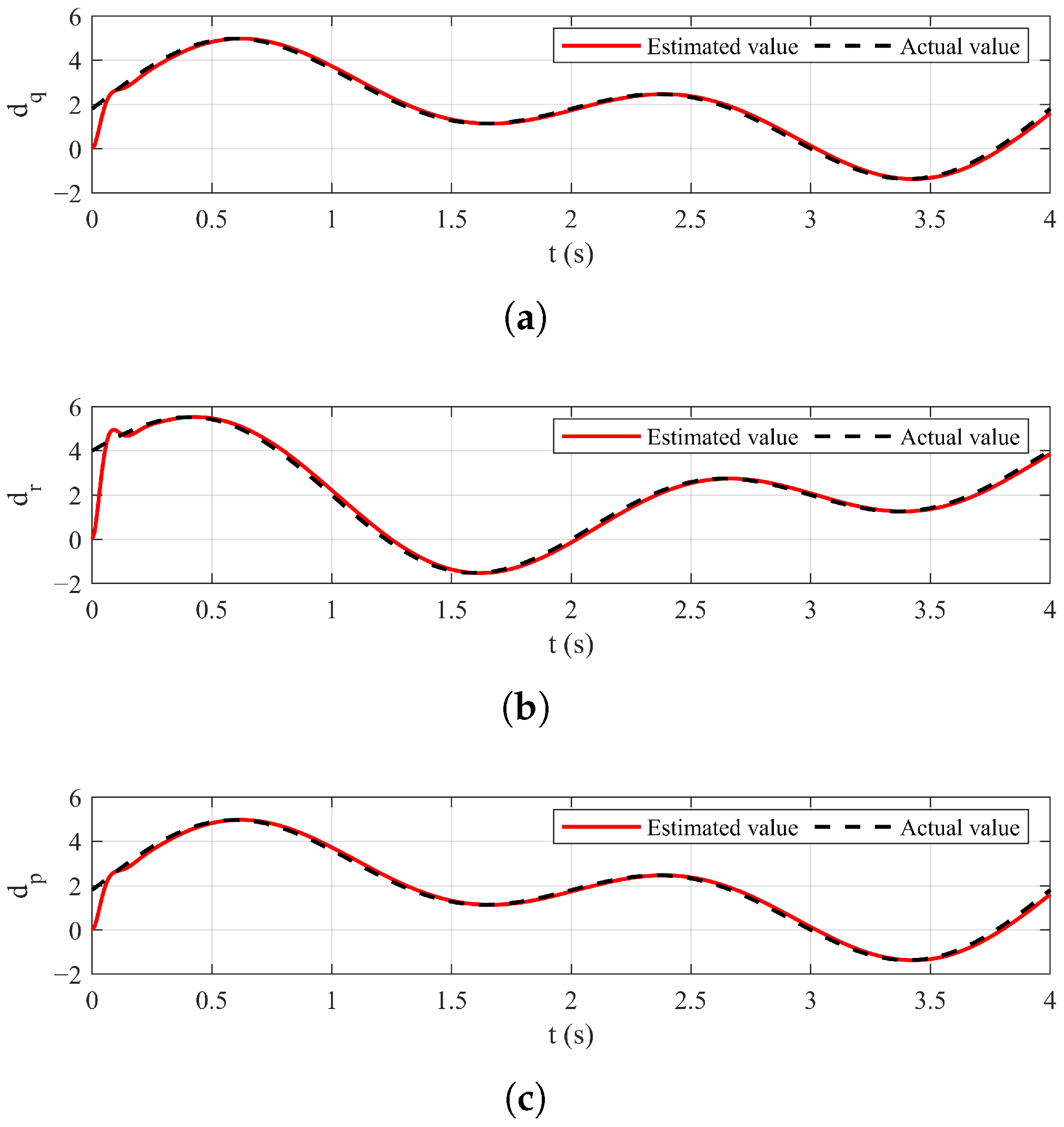
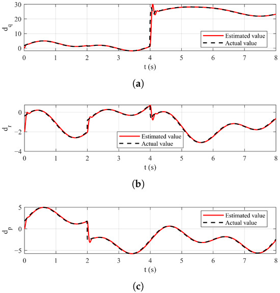
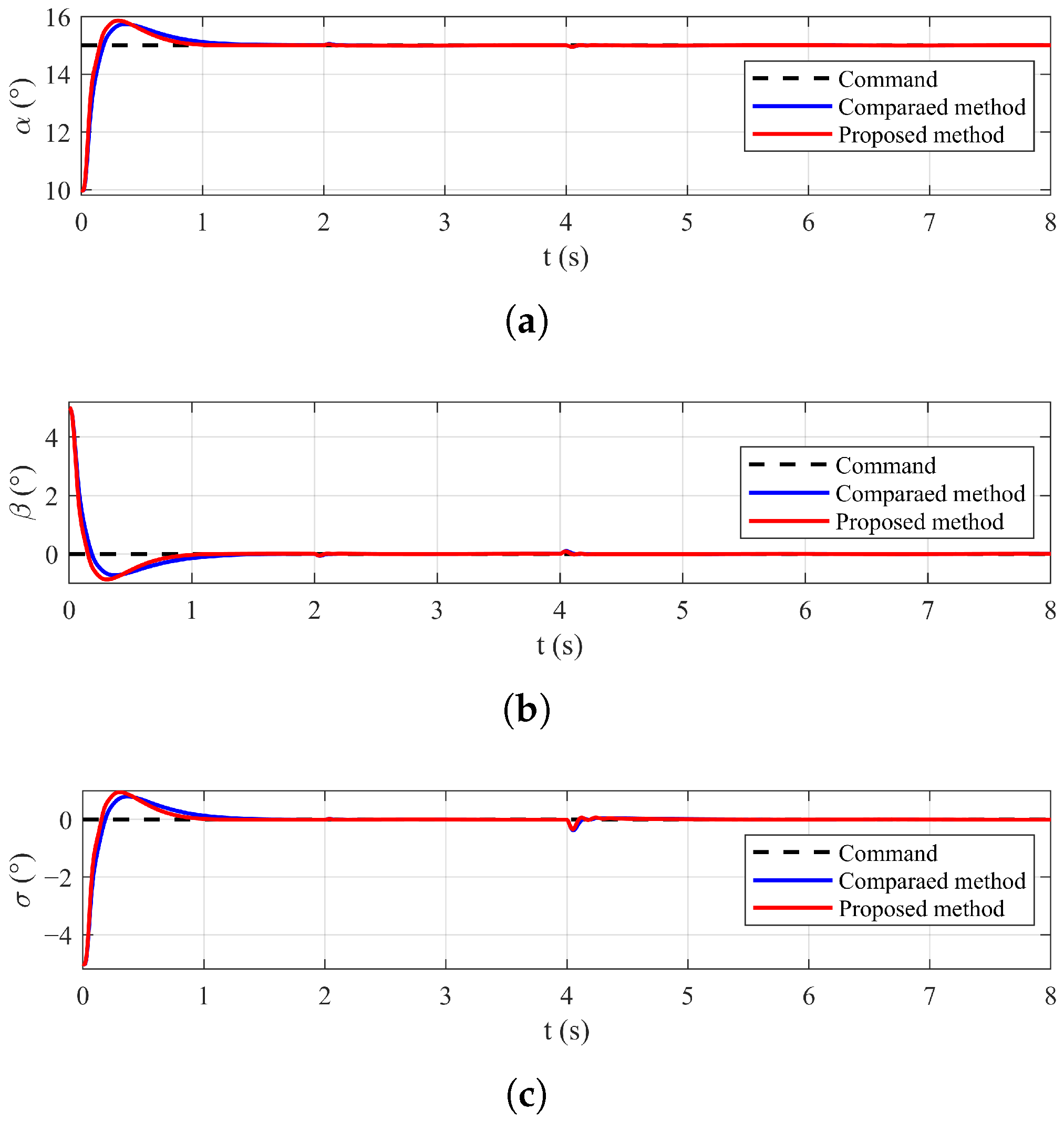
To evaluate the robustness of both controllers, the external disturbance is introduced into the simulation. Figure 4 and Figure 5 demonstrate that the ESO can robustly estimate the lumped disturbance for both methods. The simulation results are shown in Figure 6, Figure 7 and Figure 8, which present the attitude angles, angular rates, and control surface deflections for the three channels, respectively. The results show that both controllers maintain accurate attitude tracking despite the external disturbance. Meanwhile, the control deflections vary continuously to counteract the disturbance. A comparison of Table 3 and Table 4 shows that the proposed method maintains superior overall performance relative to the compared method. The transient performance of the proposed method is little affected by external disturbance on the and channels. Its settling speed on the channel and tracking accuracy are only slightly affected. In contrast, the performance of the compared method degrades noticeably, with a pronounced increase in settling time. The results further demonstrate the enhanced robustness of the proposed controller. Moreover, the peak control deflections for both methods remain below the saturation limits.
Figure 4.
Disturbance observers performance of the compared method under external disturbance: (a) Pitch channel. (b) Yaw channel. (c) Roll channel.
Figure 5.
Disturbance observers performance of the proposed method under external disturbance: (a) Pitch channel. (b) Yaw channel. (c) Roll channel.
Figure 6.
Attitude angle responses under external disturbance: (a) Angle of attack response. (b) Sideslip angle response. (c) Bank angle response.
Figure 7.
Attitude angular rates responses under external disturbance: (a) Pitch rate response. (b) Yaw rate response. (c) Roll rate response.
Figure 8.
Control surface deflections under external disturbance: (a) deflection. (b) deflection. (c) deflection. (d) deflection.
Table 4.
Performance indexes under external disturbance.
4.1.3. Verification Under Disturbance and Actuator Faults
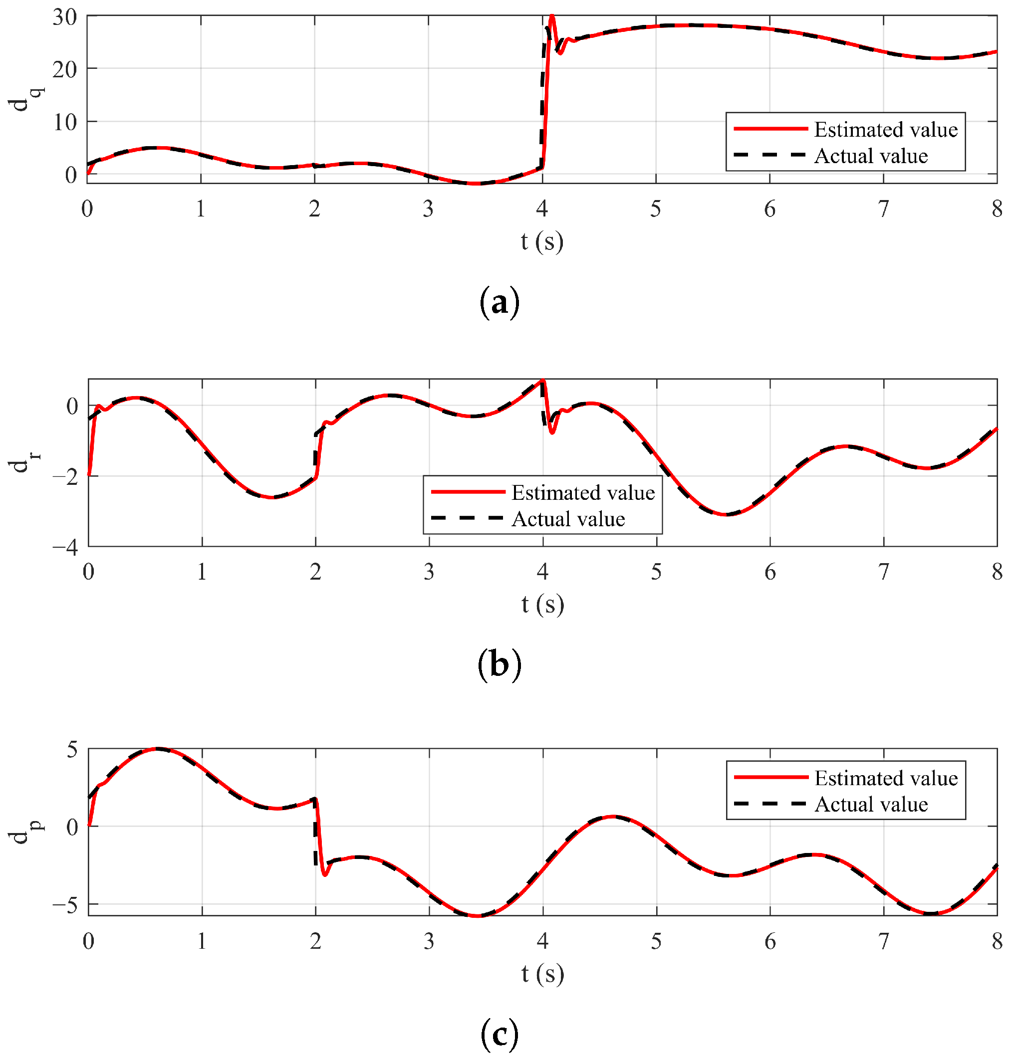
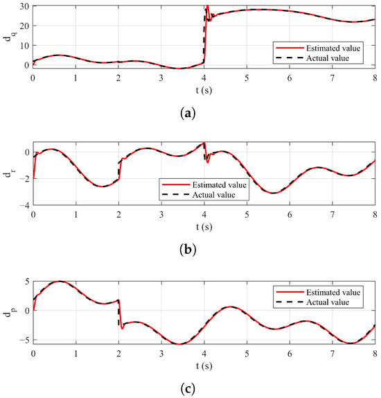
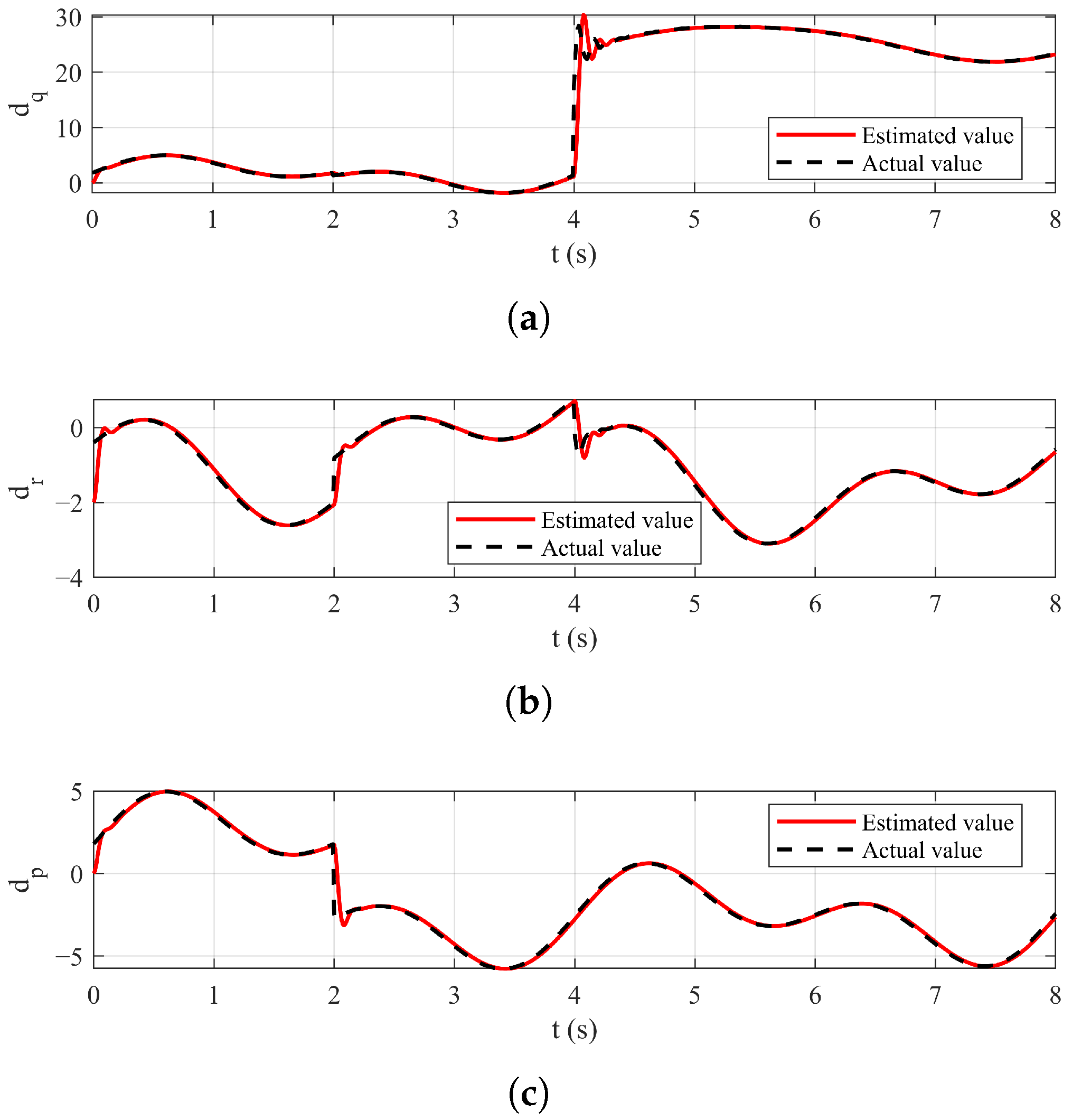
The external disturbance and actuator faults are simultaneously considered to further validate the fault-tolerant capability of both controllers. The external disturbance is set to remain consistent with the previous subsection. A bias fault is introduced in the lower rudder at s. Then, at s, the left elevon and the upper rudder suffer a 40% loss of effectiveness. Figure 9 and Figure 10 demonstrate that the ESO maintains stable estimates of the lumped disturbance in both methods. Figure 11, Figure 12 and Figure 13 illustrate the results on the three channels for the attitude angle responses, attitude angular rates, and control surface deflections, respectively. Despite the external disturbance and actuator faults, the attitude angles of both controllers converge to the command signals. Due to strong coupling among the channels, each fault instantaneously affects all channels. The remaining actuators respond promptly to compensate for the faults. Moreover, the control inputs simultaneously counteract the external disturbance. The results in Table 5 indicate that the proposed method maintains superior tracking performance and fault-tolerant capability under disturbance and actuator faults, as evidenced by the lower IAE and ITAE values across all channels. Furthermore, the peak control deflections for both methods remain below the saturation limits.
Figure 9.
Disturbance observers performance of the compared method under external disturbance and actuator faults: (a) Pitch channel. (b) Yaw channel. (c) Roll channel.
Figure 10.
Disturbance observers performance of the proposed method under external disturbance and actuator faults: (a) Pitch channel. (b) Yaw channel. (c) Roll channel.
Figure 11.
Attitude angle responses under external disturbance and actuator faults: (a) Angle of attack response. (b) Sideslip angle response. (c) Bank angle response.
Figure 12.
Attitude angular rates responses under external disturbance and actuator faults: (a) Pitch rate response. (b) Yaw rate response. (c) Roll rate response.
Figure 13.
Control surface deflections under external disturbance and actuator faults: (a) deflection. (b) deflection. (c) deflection. (d) deflection.
Table 5.
Performance indexes under external disturbance and actuator faults.
4.2. Influence of Parameters
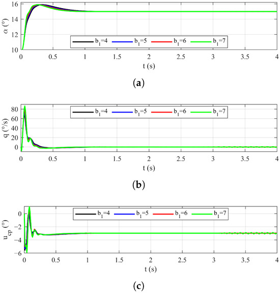
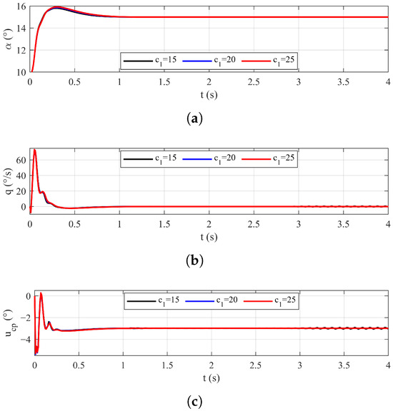
To investigate the influence of the design parameters, four comparative simulations are conducted. Given the similar trends observed across all three channels, the results and performance indices from only the pitch channel are presented as representative. In each simulation, only one selected parameter is varied, while all other design parameters and initial conditions are held constant as specified in Table 1 and Table 2. The notation “N/A” in the tables indicates that the system fails to settle.
4.2.1. The Effect of Different
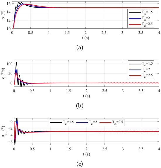
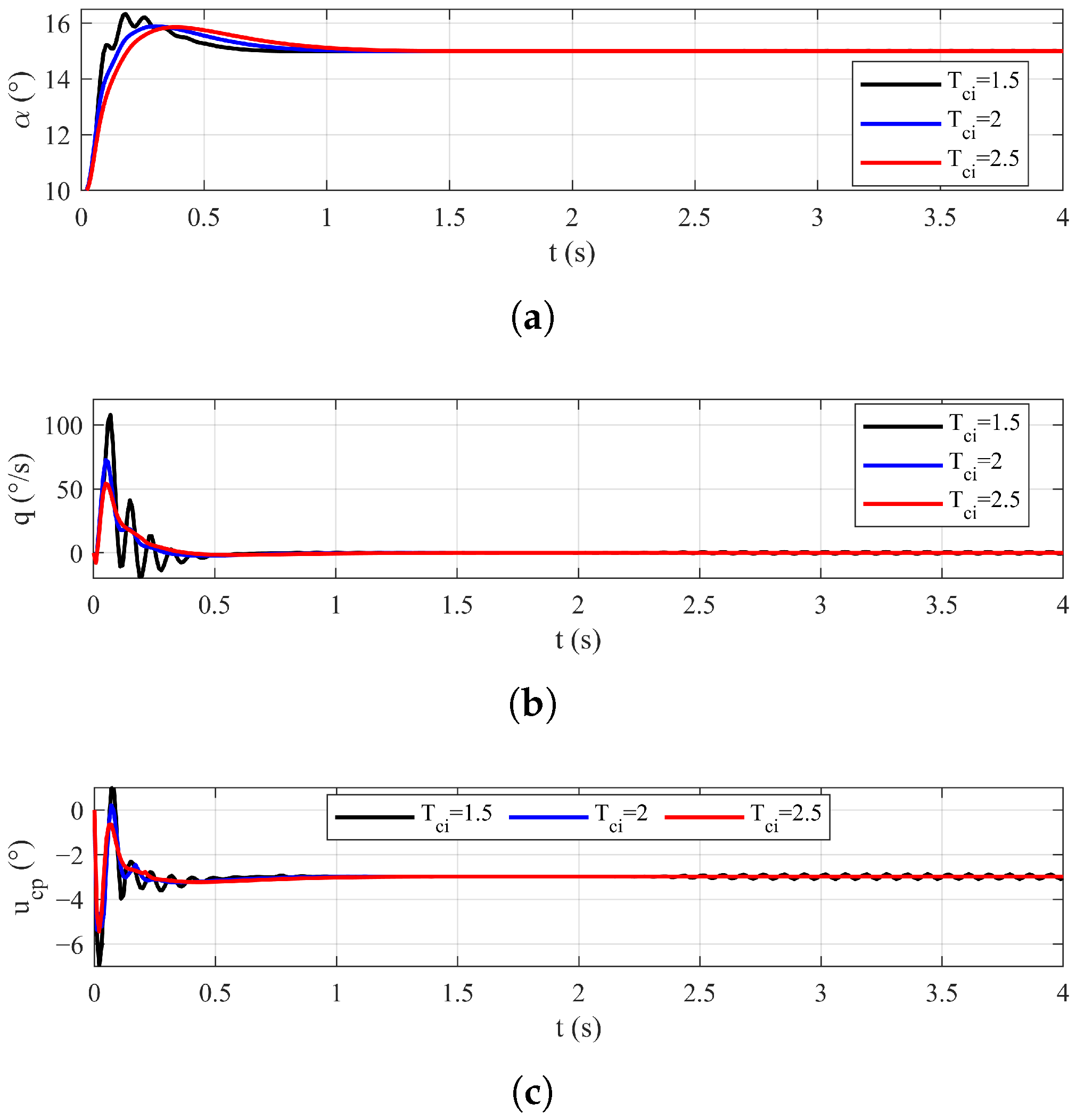
As shown in Figure 14, varying the value of parameter alters the response speed. The response speed decreases monotonically as increases from 1.5 to 2.5. However, as seen in Figure 14 and Table 6, an excessively small , which corresponds to a high control gain, induces significant oscillations in the angle of attack, pitch rate, and control command signal, preventing the system from converging. In summary, serves as a significant parameter for presetting the settling time, but it should be set sufficiently high to avoid instability.
Figure 14.
Control performance for different , : (a) Angle of attack responses. (b) Pitch rate responses. (c) Control command signal for the pitch channel.
Table 6.
Settling time for different , .
4.2.2. The Effect of Different a
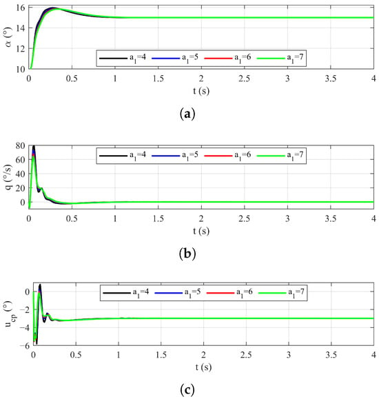
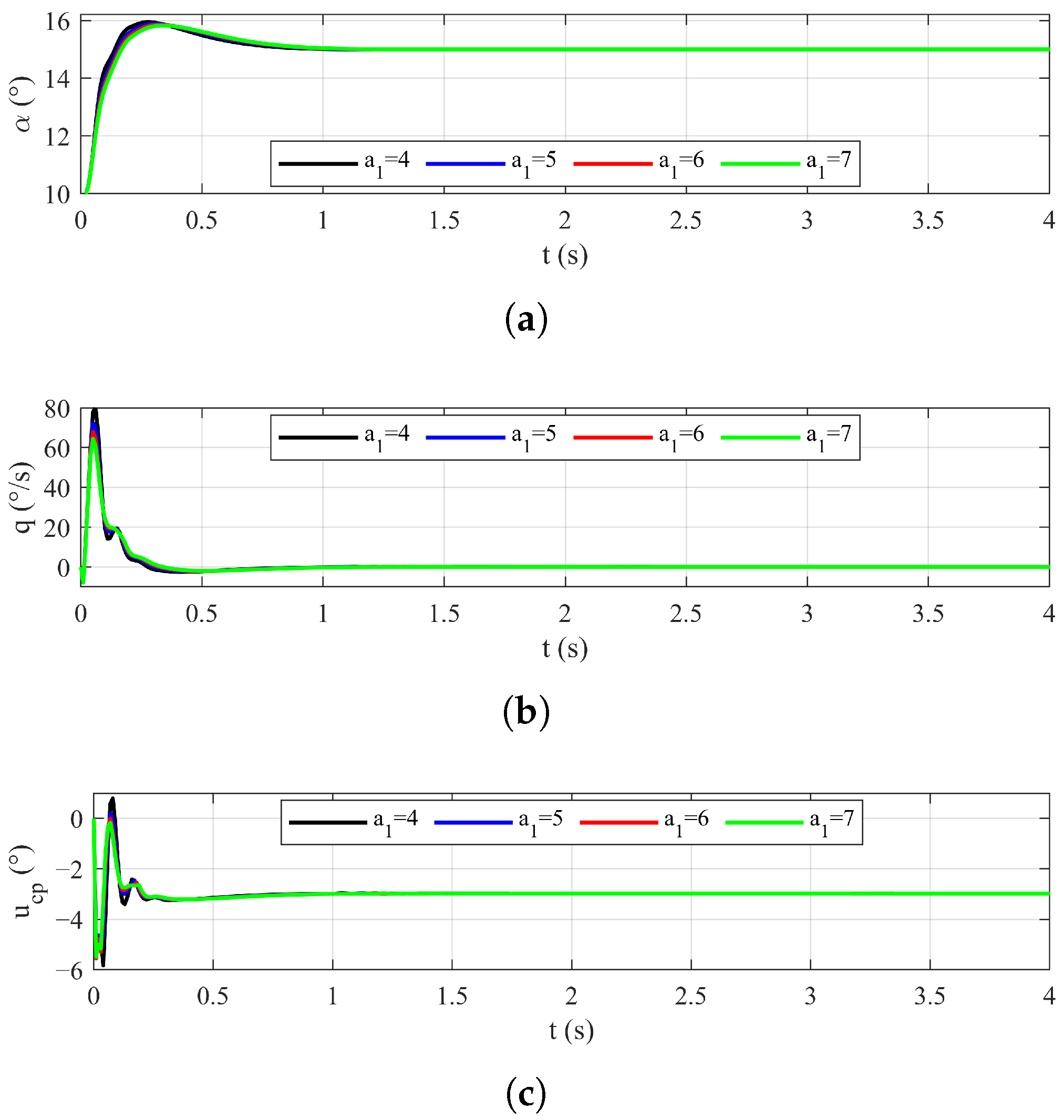
The parameter is selected as a representative case to examine the effect of the parameter a. The results shown in Figure 15 and Table 7 demonstrate the influence of parameter on the settling time. The settling time increases monotonically as increases from 5 to 7, whereas setting induces chattering and results in a longer settling time.
Figure 15.
Control performance for different : (a) Angle of attack responses. (b) Pitch rate responses. (c) Control command signal for the pitch channel.
Table 7.
Settling time for different .
4.2.3. The Effect of Different b
The parameter is selected as a representative case to examine the effect of the parameter b. The results are shown in Figure 16 and Table 8. In contrast to the effect of , the settling time exhibits a negative correlation with . When increases to 7, the system begins to exhibit chatter.
Figure 16.
Control performance for different : (a) Angle of attack responses. (b) Pitch rate responses. (c) Control command signal for the pitch channel.
Table 8.
Settling time for different .
4.2.4. The Effect of Different c
The parameter is selected as a representative case to examine the effect of the parameter c. The corresponding results are presented in Figure 17 and Table 9. The settling time increases as increases. For , the settling time is the shortest; however, this is achieved at the cost of induced obvious chattering.
Figure 17.
Control performance for different : (a) Angle of attack responses. (b) Pitch rate responses. (c) Control command signal for the pitch channel.
Table 9.
Settling time for different .
5. Conclusions and Future Work
This study proposes an improved predefined-time sliding mode fault-tolerant controller for hypersonic vehicle attitude tracking. First, a novel sufficient condition of the Lyapunov function is established and rigorously proved to guarantee both PTS and PPTS. Subsequently, a predefined-time sliding mode controller is developed, which provides additional tuning parameters for flexible performance adjustment. The proposed controller guarantees that the tracking errors converge to a neighborhood of the origin within a predefined time during both the reaching and sliding phases, with the settling time for each phase being independently adjustable. Finally, the method is validated through numerical simulations of hypersonic vehicle attitude tracking, with performance comparisons against an existing method under three different conditions. Simulation results demonstrate that, compared to the existing method, the proposed controller achieves significantly faster convergence, lower tracking errors, reduced chattering, and enhanced robustness. Furthermore, four groups of simulations are conducted to analyze the influence of key design parameters on the system performance.
The results indicate the proposed method exhibits superior convergence speed and accuracy, which demonstrates its potential for practical applications. However, a limitation of the method is that the improved control performance entails increased parameter tuning complexity. In addition, the ESO applied in this paper, as a conventional observer, has certain limitations. Future work will therefore focus on incorporating predefined-time theory into the observer design to enhance its convergence performance.
Author Contributions
Conceptualization, methodology, and software, Y.Z.; validation, T.L.; writing—original draft preparation, Y.Z.; writing—review and editing, Y.Z., T.L. and H.Y.; supervision, H.Y.; project administration, W.C. All authors have read and agreed to the published version of the manuscript.
Funding
This research received no external funding.
Data Availability Statement
All the data used to support the findings of this study are included within the article.
Conflicts of Interest
The authors declare no conflicts of interest.
References
- Chen, F.; Hu, Q.; Han, T. Predefined-Time Fault Tolerant Control for Hypersonic Vehicles Under Actuator Faults. In Advances in Guidance, Navigation and Control: Lecture Notes in Electrical Engineering; Yan, L., Duan, H., Deng, Y., Eds.; Springer Nature: Singapore, 2025; pp. 77–85. [Google Scholar]
- Jiang, R.; Zhou, J.; Guo, J. Stochastic precision analysis of hypersonic flight vehicle attitude control system in the presence of uncertainties. Syst. Sci. Control Eng. 2020, 8, 277–287. [Google Scholar] [CrossRef] [Scilit]
- Xu, S.; Wei, C.; Zhang, L.; Mu, R. Neural network based adaptive nonsingular practical predefined-time fault-tolerant control for hypersonic morphing aircraft. Chin. J. Aeronaut. 2024, 37, 421–435. [Google Scholar] [CrossRef] [Scilit]
- Li, A.; Hu, X.; Dong, K.; Xiao, B. Reconfigurable fault-tolerant attitude control for over-actuated hypersonic flight vehicle with actuator failures. Alex. Eng. J. 2025, 114, 463–475. [Google Scholar] [CrossRef] [Scilit]
- Hu, C.; Tang, Y.; Mi, H.; Yang, X.; Hu, Y. Tube-Based Composite Fault-Tolerant Control Method for Flexible Hypersonic Vehicle. Int. J. Aeronaut. Space Sci. 2025, 26, 196–219. [Google Scholar] [CrossRef] [Scilit]
- Gou, X.; Liu, J.; Zhang, Q. Adaptive backstepping fault-tolerant control for hypersonic aircraft with unknown control direction under actuator and sensor faults. Aeronaut. J. 2023, 128, 1183–1203. [Google Scholar] [CrossRef] [Scilit]
- Luo, R.; He, J.; Li, Y.; Bu, X.; Li, Q. Appointed-Time Fuzzy Fault-Tolerant Control of Hypersonic Flight Vehicles with Flexible Predefined Behaviors. IEEE Trans. Autom. Sci. Eng. 2025, 22, 13995–14007. [Google Scholar] [CrossRef] [Scilit]
- Zhang, Y.; Han, W.; Fan, Q. Finite-time fault-tolerant attitude control for hypersonic reentry vehicle based composite learning observer. IEEE Asian J. Control 2025. online version of record. [Google Scholar] [CrossRef] [Scilit]
- Huang, T.; Li, T.; Chen, C.L.P. Adaptive Tracking Control for a Quadrotor System Subject to Internal and External Uncertainties. IEEE Trans. Circuits Syst. II Express Briefs 2023, 70, 1099–1103. [Google Scholar] [CrossRef] [Scilit]
- Van, M. Higher-order terminal sliding mode controller for fault accommodation of Lipschitz second-order nonlinear systems using fuzzy neural network. Appl. Soft Comput. 2021, 104, 107186. [Google Scholar] [CrossRef] [Scilit]
- Haimo, V.T. Finite Time Controllers. SIAM J. Control Optim. 1986, 24, 760–770. [Google Scholar] [CrossRef] [Scilit]
- Chen, W.; Fan, Z. Strict finite-time sliding mode control for a tethered space net robot. Chin. J. Aeronaut. 2023, 36, 325–335. [Google Scholar] [CrossRef] [Scilit]
- Polyakov, A. Nonlinear feedback design for fixed-time stabilization of linear control systems. IEEE Trans. Autom. Control 2012, 57, 2106–2110. [Google Scholar] [CrossRef] [Scilit]
- Han, Z. Adaptive Fixed-Time Nonsingular Terminal Sliding Mode Attitude Tracking Control for Spacecraft with Actuator Saturations and Faults. Int. J. Aerosp. Eng. 2021, 2021, 8838784. [Google Scholar] [CrossRef] [Scilit]
- Zhang, H.; Wang, P.; Tang, G.; Bao, W. Disturbance observer-based fixed-time control for hypersonic morphing vehicles with uncertainties. Aeronaut. J. 2024, 128, 1844–1874. [Google Scholar] [CrossRef] [Scilit]
- Wang, Q.; Cao, J.; Liu, H. Adaptive Fuzzy Control of Nonlinear Systems with predefined-time and Accuracy. IEEE Trans. Fuzzy Syst. 2022, 30, 5152–5165. [Google Scholar] [CrossRef] [Scilit]
- Sánchez-Torres, D.J.; Gómez-Gutiérrez, D.; López, E.; Loukianov, A.G. A class of predefined-time stable dynamical systems. IMA J. Math. Control Inf. 2018, 35, i1–i29. [Google Scholar] [CrossRef] [Scilit]
- Li, Q.; Yue, C. Predefined-Time Polynomial-Function-Based Synchronization of Chaotic Systems via a Novel Sliding Mode Control. IEEE Access 2020, 8, 162149–162162. [Google Scholar] [CrossRef] [Scilit]
- Xue, H.; Liu, X. A novel fast terminal sliding mode with predefined-time synchronization. Chaos Solitons Fractals 2023, 175, 114049. [Google Scholar] [CrossRef] [Scilit]
- Liu, J.; Li, R. Novel predefined-time stability theory and its application in sliding mode control of synchronizing chaotic systems. Rev. Sci. Instrum. 2024, 95, 124702. [Google Scholar] [CrossRef] [Scilit]
- Jin, L.; Su, L.; Fei, X.; Wang, K.; Shen, H. Adaptive neural inverse optimal control for uncertain switched nonlinear systems: An improved predefined-time method. J. Control Decis. 2024, 1–15. [Google Scholar] [CrossRef] [Scilit]
- Song, J.; Ren, X.; Na, J.; Gong, J.; Zheng, D. Enhanced Predefined-Time Tracking and Synchronization Control for Multimotor Servo Systems. IEEE Trans. Ind. Electron. 2025, 72, 7094–7105. [Google Scholar] [CrossRef] [Scilit]
- Xie, S.; Chen, Q. Adaptive Nonsingular Predefined-Time Control for Attitude Stabilization of Rigid Spacecrafts. IEEE Trans. Circuits Syst. II Express Briefs 2022, 69, 189–193. [Google Scholar] [CrossRef] [Scilit]
- Kong, X.; Sun, Y.; Guo, Y.; Ma, G.; Gong, Y. Predefined-Time Control of a Spacecraft Attitude with Thrust Booms. Aerospace 2023, 10, 94. [Google Scholar] [CrossRef] [Scilit]
- Sui, S.; Chen, C.L.P.; Tong, S. Command Filter-Based Predefined-Time Adaptive Control for Nonlinear Systems. IEEE Trans. Autom. Control 2024, 69, 7863–7870. [Google Scholar] [CrossRef] [Scilit]
- Wang, J.; Liu, L.; Zhao, T.; Tang, G. Integrated guidance and control for hypersonic vehicles in dive phase with multiple constraints. Aerosp. Sci. Technol. 2016, 53, 103–115. [Google Scholar] [CrossRef] [Scilit]
- Chen, H.; Song, S.; Zhu, Z. Robust finite-time attitude tracking control of rigid spacecraft under actuator saturation. Int. J. Control Autom. Syst. 2018, 16, 1–5. [Google Scholar] [CrossRef] [Scilit]
- Yu, X.; Li, P.; Zhang, Y. Fixed-Time Actuator Fault Accommodation Applied to Hypersonic Gliding Vehicles. IEEE Trans. Autom. Sci. Eng. 2021, 18, 1429–1440. [Google Scholar] [CrossRef] [Scilit]
- Chen, P.; Cheng, Y.; Yuan, Y.; Hua, L. Sliding Mode Tension Control for the Yarn Winding Process with Extended State Observer. Trans. Inst. Meas. Control 2025, 47, 291–303. [Google Scholar] [CrossRef] [Scilit]
- Tang, J.; Dang, Z.; Deng, Z.; Li, C. Adaptive fuzzy nonlinear integral sliding mode control for unmanned underwater vehicles based on ESO. Ocean. Eng. 2022, 266, 113154. [Google Scholar] [CrossRef] [Scilit]
- Guo, B.; Zhao, Z. On Convergence of the Nonlinear Active Disturbance Rejection Control for MIMO Systems. SIAM J. Control Optim. 2013, 51, 1727–1757. [Google Scholar] [CrossRef] [Scilit]
- Jia, C.; Liu, X.; Xu, J. Predefined-Time Nonsingular Sliding Mode Control and Its Application to Nonlinear Systems. IEEE Trans. Ind. Inform. 2024, 20, 5829–5837. [Google Scholar] [CrossRef] [Scilit]

Disclaimer/Publisher’s Note: The statements, opinions and data contained in all publications are solely those of the individual author(s) and contributor(s) and not of MDPI and/or the editor(s). MDPI and/or the editor(s) disclaim responsibility for any injury to people or property resulting from any ideas, methods, instructions or products referred to in the content. |
© 2026 by the authors. Licensee MDPI, Basel, Switzerland. This article is an open access article distributed under the terms and conditions of the Creative Commons Attribution (CC BY) license.