


Abstract
Active vibration isolation via magnetic levitation provides an effective solution to the micro-vibration problem of high-precision satellites. However, limited volume and mass constraints of the satellites demand the active vibration isolation platform to be ultra-compact yet with high thrust density. This paper presents a slim magnetically levitated actuator (thickness < 20 mm) based on modified Halbach bi-array, which intensifies air gap flux density while minimizing flux leakage. An analytical electromagnetic model of the proposed actuator is developed using an infinitesimal current element integration method, enabling accurate and efficient prediction of magnetic field distribution and thrust force. Leveraging the proposed model, an augmented FxLMS adaptive controller is implemented with its secondary path initialized via a physics-based simulation and then refined experimentally through white-noise identification. The experiment verifies that the proposed actuator produces a 11.8 N/A force constant at the nominal position and achieves an averaged 41.73 dB vibration suppression within 5–260 Hz range on a SDOF active vibration isolation platform. These results confirm the great potential of the proposed electromagnetic actuator in micro-vibration control of high-precision satellites.
1. Introduction
For in-orbit spacecraft and satellites, a diversity of sources of disturbances, including attitude maneuver, solar panel sun-tracking, cyclic thermal loading, etc., cause a broadband, small-amplitude vibration, called micro-vibration [1]. Undesired micro-vibration could significantly affect the imaging quality, pointing accuracy, and detection resolution of the sensitive payload, compromising its functionality and lifetime. Micro-vibration attenuation has been a prolonged problem for aerospace engineering. The well-known Hubble Space Telescope suffered from the solar array-induced disturbance, which caused a pointing accuracy degradation from 0.007 to 0.1 arcsec, until a combination of mechanical changes and an enhanced disturbance control system were implemented [2]. A simulation-based study about the Main Survey Camera mounted on the China Space Station Telescope suggests that the velocity aberration effect leads to a 0.94 pixel offset for a 20 min exposure at low ecliptic latitude [3]. With the vast development of aerospace engineering and exploration of deep space, requirements for accuracy and stability of spacecraft and satellites have rapidly elevated. For example, the TianQin project, which is a space-based gravitational wave observatory, requires the pointing accuracy of the associated platform to be less than 0.002 arcsec [4].
Typically, the micro-vibration spreads in the frequency range from 0.1 Hz to several hundred Hz [5]. The extreme low-frequency vibrations are usually caused by the flexible vibrational modes of the solar arrays. Because of low damping rates, those low-frequency vibrations persist for a long time once induced by maneuvers or thermal shocks [6]. Vibrations with frequencies above 10–30 Hz are mainly caused by flywheels, gyroscopes, and other actuators. Unlike the solar array-induced low-frequency vibrations, those high-frequency vibrations are broadband and heterogeneously originated, making their suppression difficult and costly [7]. During the past few decades, various vibration isolation methodologies have been developed for micro-vibration mitigation [8,9,10,11]. Vibration isolation techniques can be categorized as passive methods, semi-active methods, and active methods. Passive isolation methods are the most widely used techniques in aerospace engineering. A passive isolator can reject vibrations above its natural frequency or cut-off frequency with a low transmittance. Semi-active isolation is a type of hybrid method that offers better isolation performance than passive isolators, and more reliability than active isolators. A conventional approach is to replace the passive stiffness or damping with tunable elements, leveraging electrorheological fluids [12], magnetorheological fluids [13], and other smart materials [14]. More recently, semi-active electromagnetic quasi-zero-stiffness isolators [15] and hybrid active–passive platforms with two-axis Lorentz actuators [16] have been explored to improve low-frequency vibration isolation performance. Although passive and semi-active isolation techniques have advantages such as simplicity, reliability, and low cost, their isolation performance degrades when faced with low-frequency, small-amplitude micro-vibration. Under these circumstances, active vibration isolation methods are highly demanded.
Active vibration isolation (AVI) usually aims at suppressing low-frequency micro-vibration based on active control strategies. The Stewart platform is one of most frequently investigated AVI systems, which generally consists of an upper platform, a base platform, and six actively actuated struts. Since every strut is actuated independently, the Stewart platform is able to provide six-degree-of-freedom motion control [17]. Despite its advantages of high pointing accuracy and stability, Stewart platforms have several inherent drawbacks, including structural complexity, bulk space occupation, and joint-related contact and friction issues. In addition, the coupled parallel mechanism and nonlinear geometry make it more challenging for control and sensing strategy design [17]. To address these challenges, magnetic levitation-based AVI has emerged as a promising alternative for spacecraft micro-vibration control. Recent research has demonstrated that magnetically levitated double-stage platforms based on Stewart configuration with Lorentz force actuators can eliminate mechanical contact and improve pointing accuracy and vibration isolation [18], while entirely contact-free magnetic bearing systems have been proposed for satellite attitude control with enhanced pointing precision [19,20]. Magnetic levitation-based platforms are a type of non-contact vibration isolation systems that are inherently free of friction and contact nonlinearities. Capable of providing large strokes, maglev vibration isolation platforms are extensively applied in low-frequency micro-vibration isolation scenarios. Various ground prototypes have been reported, including modular platforms with integrated two-degree-of-freedom Lorentz actuators [21] and six-degree-of-freedom Halbach array-based isolation systems for ultra-precision instruments [22]. Many box-type active maglev isolation systems have been tested and utilized on various orbiting platforms, including the international space station and China’s Tianzhou-1 cargo spacecraft. Although those microgravity vibration isolation systems proven very effective in delivering an ultra-stable science environment, their bulky sizes prevent direct application on small and compact spacecrafts, such as communication and remote sensing satellites.
Lorentz actuators are key components of maglev vibration isolation systems. For maglev vibration isolation systems utilized in space environments, a higher thrust density is always desired due to the expensive launching cost. Various Lorentz actuator configurations have been explored to enhance thrust density, reduce force ripple, and achieve multi-axis decoupled actuation [23,24,25]. The Halbach array, known for its flux concentration and self-shielding capability, has been adopted in tubular oscillating motors and magnetically levitated stages to further improve force density [26,27]. For a thickness-limited planar actuator, the Halbach arrangement is particularly attractive because it concentrates magnetic flux toward the air gap side while suppressing the opposite-side leakage field, thereby increasing the usable force density within a constrained form factor. In addition, accurate analytical modeling of magnetic field and force characteristics remains a critical step for actuator design and optimization [28,29].
In order to get a greater actuation force, this paper proposes a novel slim magnetic levitated actuator based on modified Halbach bi-arrays. With the help of Halbach bi-arrays, the actuator can achieve more concentrated magnetic flux in the air gap while suppressing the leakage flux, hence producing greater thrust forces. An analytical electromagnetic model with iterative back yoke characterization is established to provide efficient and accurate prediction of magnetic field and force performance. With the proposed analytical method, we have performed a through parameter analysis for optimal design. With the help of the analytical mode, a physically augmented FxLMS-based feedforward controller has been implemented on an SDOF active isolation platform, demonstrating effective vibration isolation capability in a broadband frequency range.
2. Mechanical Design of the Halbach Array Actuator
The thrust force constant is an important performance metric of active electromagnetic actuators. A higher force constant allows greater actuation force with a given actuation current, which directly reduces the required control efforts in terms of both current magnitude and control gain. This is particularly advantageous in micro-vibration control of spacecraft and satellites, where lower energy consumption and heat generation as well as less nonlinearity are always desired. Compared with conventional north–south array actuators, the proposed bi-array Halbach actuator generates significantly stronger magnetic field in the air gap with improved spatial linearity.
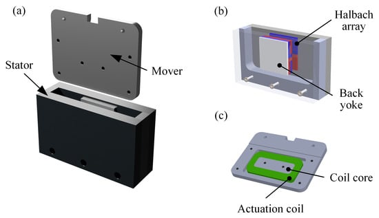
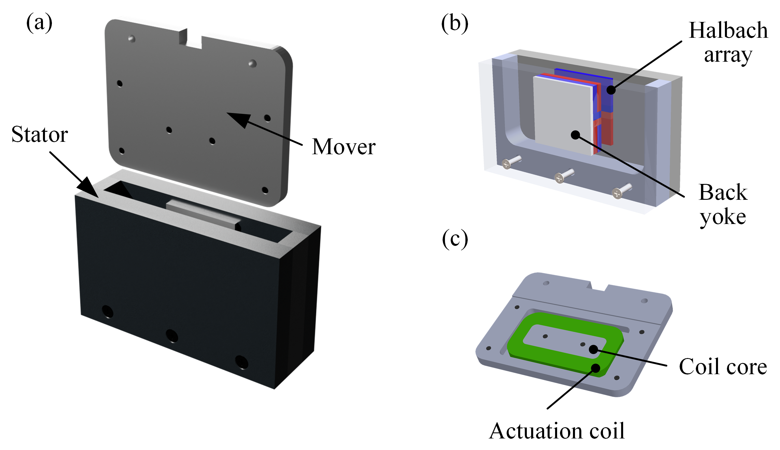
The assembly of the proposed Halbach actuator is shown in Figure 1a. The actuator adopts a compact and planar architecture, comprising two main components: a stator and a mover. The stator is rigidly mounted to a vibration-disturbed foundation and the mover is connected to the isolated platform. The stator consists of two parallel magnet host panels affixed to a non-magnetic supporting base. Each host panel integrates a modified Halbach array specifically designed to form a closed magnetic flux loop across the air gap between them. This configuration concentrates the magnetic field in the gap meanwhile minimizing the boundary leakage, resulting in an intensified flux density distribution. Mounted within the mover panel is a hollowed rectangular coil whose longer edge serves as the actuation side. The whole actuator is designed to achieve a lighter self-weight. For this purpose, both the host panels and the supporting base are fabricated with acrylonitrile styrene acrylate (ASA) polymer via 3D filament printing. The mover is made of aluminum alloy for better mechanical performance. N52 NdFeB is selected for the permanent magnets in order to maximize the available air gap flux density within the limited actuator volume. In the geometric design, our primary considerations are that the actuation coil should not contact the permanent magnets within a horizontal stroke of 2 mm, and that the overall actuator thickness (including the air gap size, back yoke thickness, magnet thickness, and coil thickness) should be as small as possible. At the same time, the resulting force constant of the actuator must be sufficiently large to support the required load, with the force constant required to exceed 10 N/A.
Figure 1.
Configuration of the proposed Halbach actuator: (a) actuator assembly; (b) stator; (c) mover.
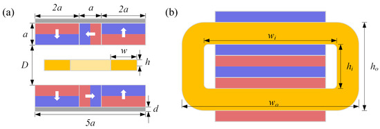
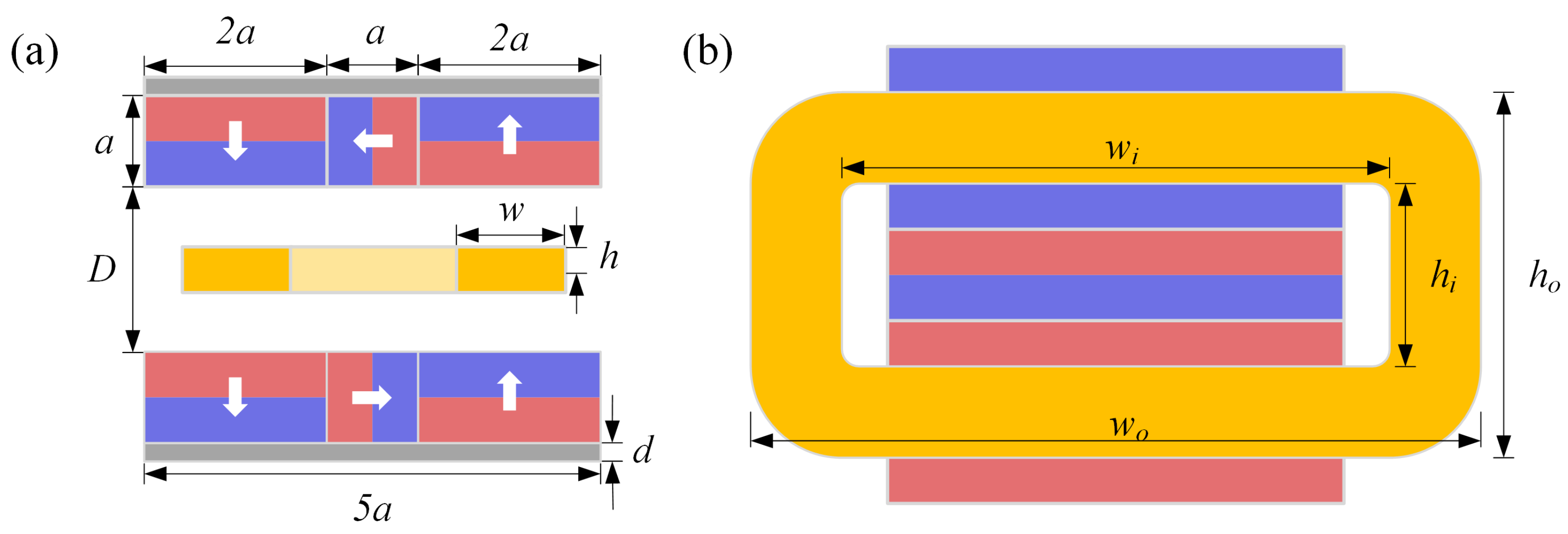
Each modified Halbach array is composed of three magnets, one with a square cross-section and two with rectangular cross-sections. The square cross-section magnets have side length a, and the rectangular cross-section magnets have thickness a and length . As shown in Figure 2a, magnetization orientation of the magnets follow the canonical Halbach pattern, rotating by 90 degrees from one block to the next to reinforce the field on the air gap side. To further enhance magnetic efficiency, a soft ferromagnetic back yoke of thickness d is attached to the rear side of each array. The actuation coil is placed with its longitudinal edge perpendicular to the array alignment direction, as shown in Figure 2b, such that the actuation coil generates a vertical thrust force. D denotes the nominal gap between the two magnet arrays, while , , , and denote the inner and outer dimensions of the rectangular actuation coil respectively. The geometric parameters of the modified Halbach array are listed in the following table.
Figure 2.
Schematic of the Halbach array architecture: (a) cross-section view, (b) normal view.
Compared with Stewart-type isolation systems, whose compactness is limited by a complete multi-axis mechanism, the present work focuses on reducing the size of the actuator module itself. As an actuator-level reference in a Stewart platform configuration, Senoner reported a hybrid-reluctance-actuated Stewart platform in which each hybrid reluctance actuator was designed with lateral dimensions of for integration into a cubic Stewart mechanism with a platform diameter of [30]. In contrast, the actuator proposed in this work adopts a slim planar configuration with an overall thickness below , aiming to reduce the out-of-plane installation height for compact non-contact integration. This low-profile geometry is intended to facilitate compact integration as a non-contact force element before multiple units are assembled into a larger isolation platform.
3. Analytical Modeling of the Halbach Array Actuator
While the finite element method (FEM) offers precise predictions of magnetic field distribution, optimization and control strategy design of the actuator still demand analytical models that are both accurate and computationally efficient. Conventional analytical modeling methods often only consider permanent magnets without accurate assessment of the influence of the back yokes. Although some alternative methods approximate the back yoke as an elongated magnet [22], such treatments still introduce discrepancies between the predicted and actual magnetic flux density. To address this issue, an analytical iterative updating scheme is developed herein to evaluate the magnetic field of a Halbach array with back yokes more accurately.
3.1. Magnetic Flux Density Model
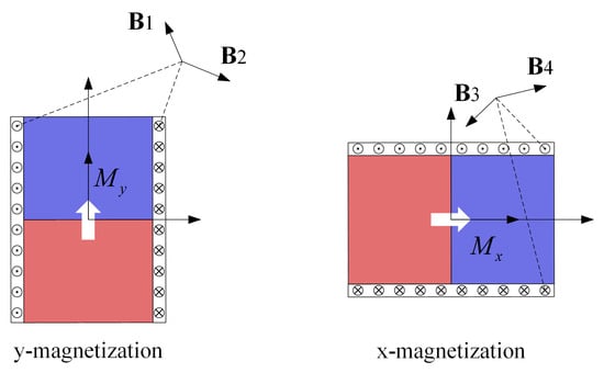
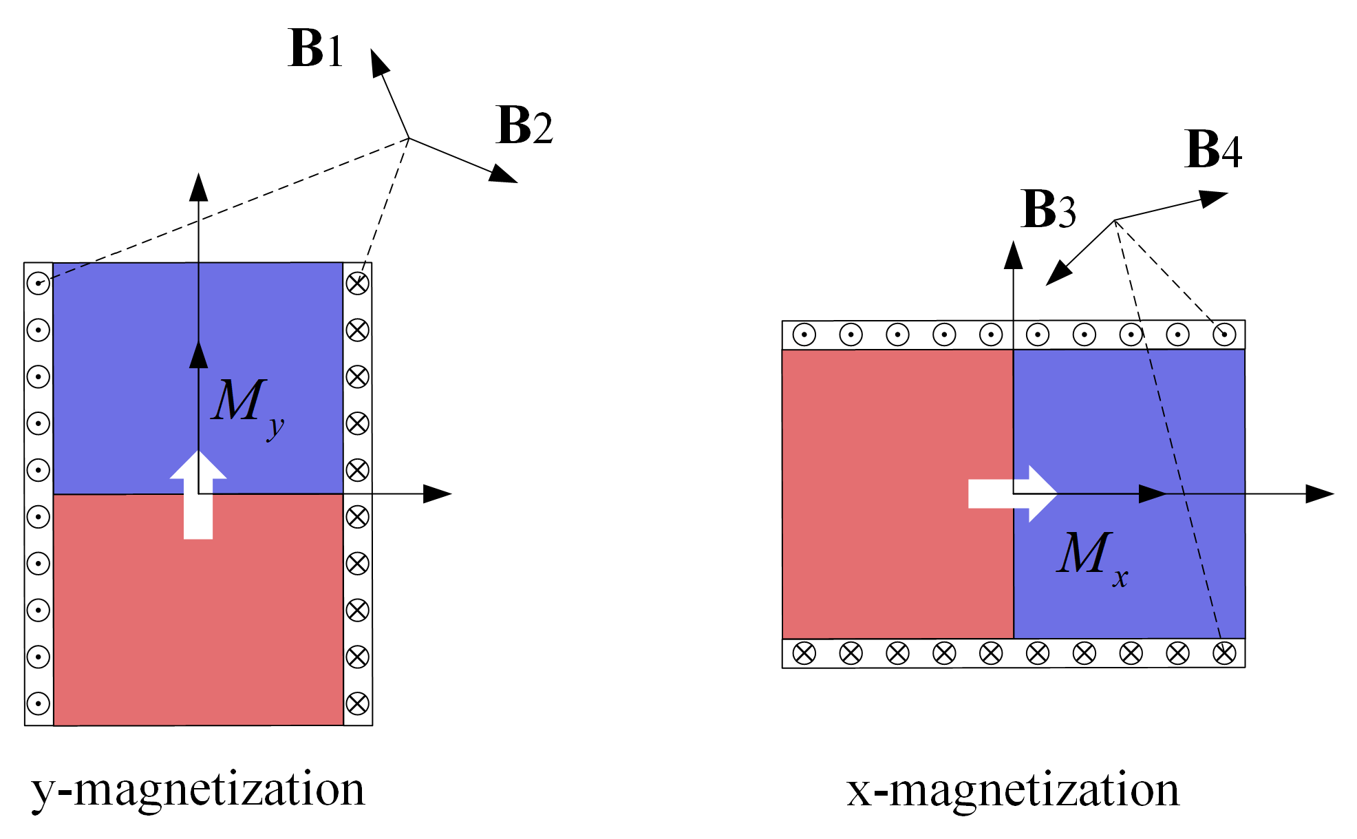
According to Ampere’s molecular current hypothesis, the magnetic field at any position outside a permanent magnet can be treated as an equivalent field induced by current loops at the surfaces of the magnet, as seen in Figure 3. Therefore, the magnetic field of a permanent magnet can be obtained by integrating the equivalent magnetic flux density caused by the infinitesimal surface current elements. Subscripts 1 and 2 correspond to the magnetic field caused by the equivalent surface currents on the left and right faces for a y-magnetized magnet, and on the top and bottom faces for an x-magnetized one.
Figure 3.
Schematic diagram of magnet current loop.
According to the Biot–Savart law, components of the magnetic flux density of a permanent magnet in the xy-plane can be determined as follows [31].
For the y-direction magnetization:
For the x-direction magnetization:
where and denote the relative magnetization intensity along the x and y axes, represents the vacuum permeability, and w and h represent the width and height of the two-dimensional magnet, respectively. A magnet with an oblique magnetization (not aligned with the x-axis nor y-axis) can be equivalent to a superposition of a horizontally magnetized magnet and a vertically magnetized magnet [32]. For such a magnet, its magnetization can be defined as , with and representing the unit vector along the x- and y-axis, respectively. The associated magnetic flux density is determined by superposition of the magnetic fields generated by two pseudo-magnets whose magnetization is the x-axis and y-axis projections, respectively. Therefore, the magnetic flux density generated by a single magnet at position can be expressed as follows:
Based on the magnetic flux of a single permanent magnet given in Equation (9), the magnetic field generated by a Halbach array can be accordingly derived via coordinate transformation as
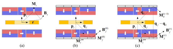
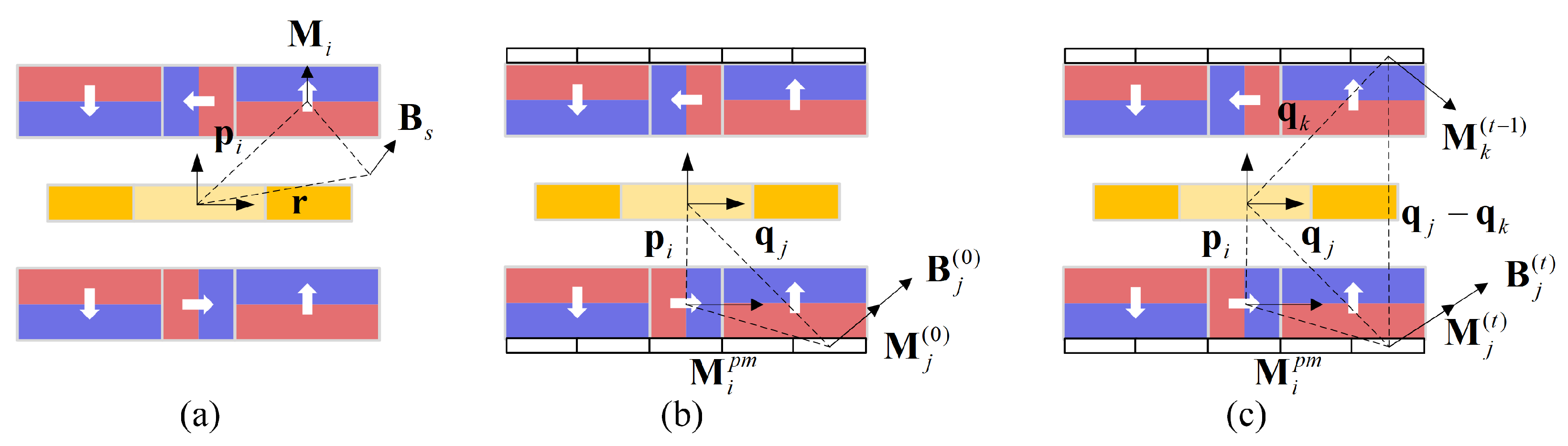
where stands for the magnetic flux density of each magnet, with and denoting the position vector of its center of mass and the magnetization, as shown in Figure 4a. Compared to the Fourier expansion method which is more suitable for periodic structures but suffers from end effects in finite-length arrays [33], the infinitesimal current element method proposed here provides a closed form solution that accurately captures the magnetic field induced by finite Halbach array.
Figure 4.
Schematics of: (a) permanent magnet array; (b) equivalent magnet model of back yoke; (c) iterative back yoke model.
3.2. Characterization of the Back Yoke
A back yoke can provide a low-reluctance return path for the magnetic flux, which significantly enhances the magnetic field concentration within the air gap. However, inclusion of ferromagnetic materials complicates the magnetic field distribution, as the back yoke further magnetizes the field generated by the permanent magnets. A common approach is to mimic the back yoke as an elongated permanent magnet with uniform magnetization, which fails to account for the nonuniform magnetization distribution. Unlike the permanent magnets, the magnetization distribution of the back yoke is nonhomogeneous due to the combined influence of the permanent magnet and the back yoke itself. In order to get a more accurate evaluation of the magnetic flux density in the air gap, the back yoke is discretized as finite units with various magnetization orientations and an iterative scheme is proposed to determine the magnetic flux density.
As shown in Figure 4b, the back yoke is divided into a finite number of equivalent units whose magnetization directions are generally oblique. The magnetic flux density generated by the back yoke can be accordingly determined by Equations (9) and (10) once its magnetization vector is known. There are permanent magnets, located at , with their magnetization vector defined as and the back yokes are divided into small units, with their center position vector defined as . In the initial iteration, all the equivalent magnets of back yokes are assumed to be magnetization free. Magnetic flux density at the j-th equivalent unit is fully determined by the permanent magnets given as
With the B-H curve of the back yoke material, the corresponding magnetization vector is obtained as follows
where denotes the flux density interpolated from the B-H curve, and is the permeability of free space. The total induced magnetic flux density at a given equivalent unit is a combination of the magnetic field generated by the permanent magnets and the magnetic field induced by the other magnetized equivalent units. The latter one can be obtained with an iterative approach. For each iteration, the total induced magnetic flux density at the center of the j-th unit is
and the associated magnetization vector is updated as
where is the magnetization of the i-th permanent magnet and is the associated magnetization vector, as shown in Figure 4c.
The termination criteria of the iteration is defined as
where denotes the relative change between iterations and is the prescribed tolerance. In the present calculations, each back yoke is divided into equivalent magnet elements. When the relative change is sufficiently small, the iteration is considered to have converged.
3.3. Coil Dynamics and Thrust Force Calculation
Since the moving coil in the magnetic field induces a back electromotive force, the current in the coil is governed by an ordinary differential equation in the following form
where U stands for the control voltage applied by the external power source, E represents the back EMF generated by the moving coil, and and are the coil resistance and inductance, respectively. According to the principle of electromagnetic induction, the back EMF E is directly related to the moving velocity of the coil and the magnetic flux density in the air gap. For a horizontally actuated coil with N turns and effective working length , the back EMF is calculated in terms of the magnetic flux density in the x-direction as
with S being the cross-sectional area of the coil working surface, v the moving velocity along the actuation direction, and the back-EMF coefficient. The magnetic flux is replaced with for a vertically actuated coil. For simplicity, the subscripts x and y are omitted in the following sections.
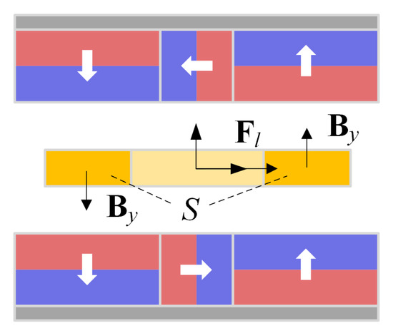
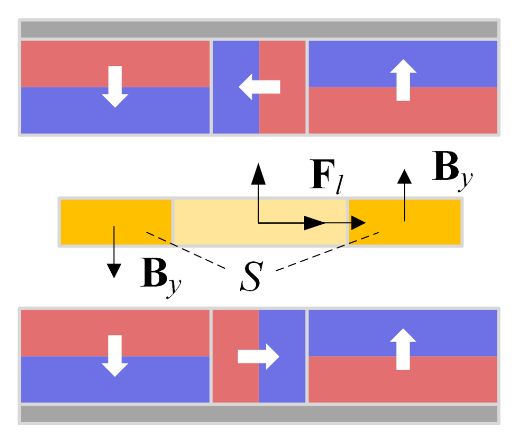
By Lorentz’s law, the Lorentz force acting on the coil is determined by the current in the coil and the magnetic flux density. Under the assumption of a uniform current density across the coil cross-section, the Lorentz force can be simplified as a linear relation characterized by the force constant in the form of
The force constant is analytically determined by integrating the magnetic flux density over the cross-section as shown in Figure 5. Detailed derivation of the analytical expression of the force constant can be found in Appendix A.
Figure 5.
Schematic diagram of the Lorentz force integral calculation.
4. Numerical Verification and Parameter Analysis
4.1. Force Constant Verification
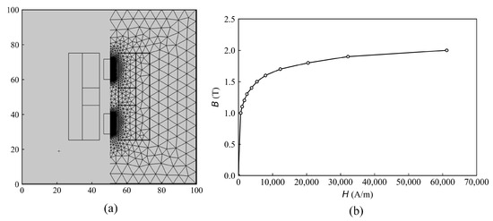
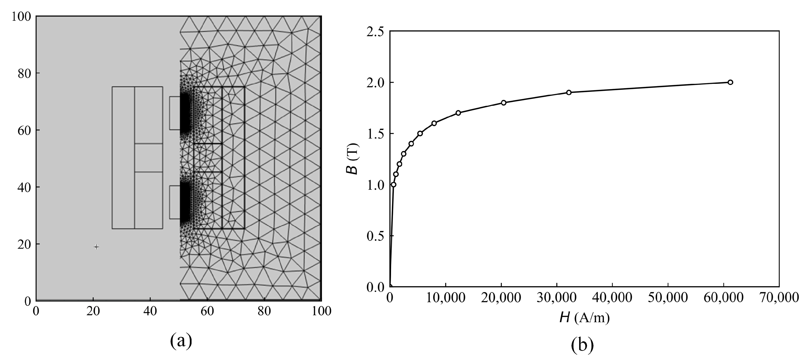
In this section, the analytical results are compared to both the numerical results obtained from finite element method (FEM) and the experimental measurements. The numerical model is built with the commercial software COMSOL Multiphysics 6.1. Due to manufacturing error, the width and the height of the actual coil are mm and mm, respectively, while the other geometric parameters remain unchanged as in Table 1. In the numerical simulation, the material of the permanent magnet is N52 (sintered NdFeB) with a remanent flux density of T and a relative permeability of , and the back yoke is made of soft iron with a thickness of 5 mm. In COMSOL, a 2D cross-section model of the magnet array and the coil is built within a air domain whose boundary is subject to a magnetic insulation condition, as shown in Figure 6a.
Table 1.
Geometric parameters of the modified Halbach array.
Figure 6.
COMSOL simulation schematic diagram: (a) mesh division diagram; (b) B-H curve.
As the analytical iterative model of the back iron requires the B-H curve, the material data points were extracted from COMSOL and the magnetization is obtained by linear interpolation (pchip) between these points as shown in Figure 6b. The moving coil has turns with an effective working length m (the factor 0.05 accounts for the out-of-plane thickness conversion from the 2D simulation, where the default thickness is 1 m).
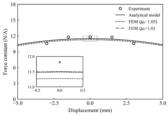
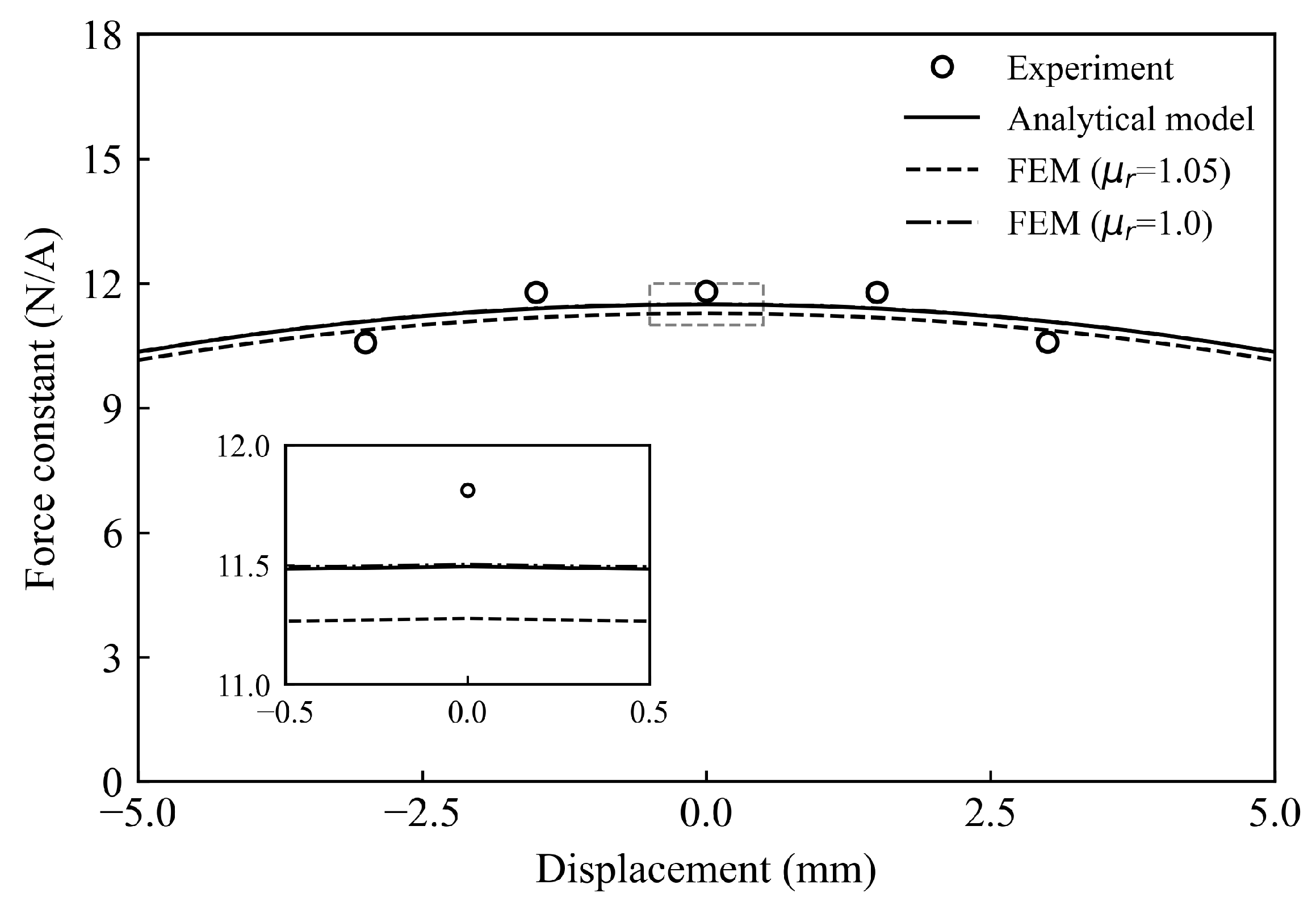
The distributions of the force constant along the actuation direction of the coil determined by the analytical model and by the COMSOL-based FEM are plotted in Figure 7. From the figure it can be seen that the analytical result is in good agreement with the FEM result within a ±5 mm range around the central position. When the relative permeability is one, the force constant at the central position from the FEM is 11.502 N/A, matching the analytical prediction of 11.49 N/A with an error of only about 0.1%, confirming that the permeability difference is the primary source of the observed error. In reality, the relative permeability of the magnet is 1.05 (instead of 1.0), which will slightly disturb the magnetic circuit. Under these conditions, the calculated center position force constant from the FEM is 11.276 N/A, and it only differs from the analytical prediction value of 11.49 N/A by approximately 1.9%. It verifies that the proposed analytical model can accurately predict the performance of the Halbach array actuator with extreme efficiency.
Figure 7.
Comparison of the relationship between displacement on the force action line and force constant coefficient for different models and experimental verification.
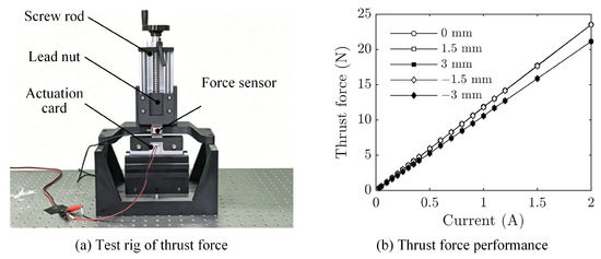
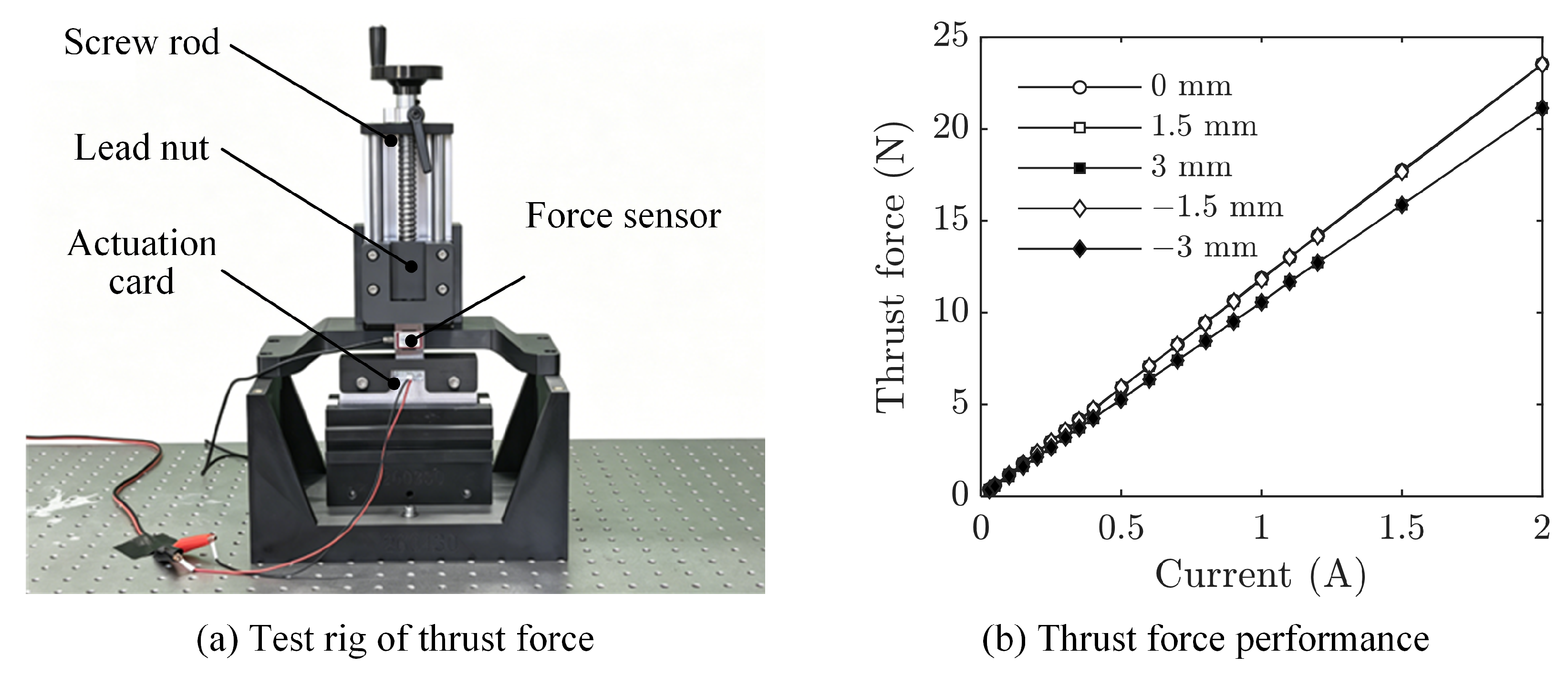
The force constant of the proposed Halbach array actuator is measured via a static thrust force test rig. As shown in Figure 8a, in order to measure the thrust force when the actuation coil is off the central position in the air gap, the test rig uses a screw rod to adjust the position of the actuation coil card. With the actuation card and the lead nut of the screw rod connected by a force sensor, the thrust force of the actuation card can be read from the output of the sensor. Five positions (0 mm, mm, and mm) are considered in the experiment and the relationships between the thrust force and the current at those positions are plotted in Figure 8b. Force constants and nonlineary ratios are calculated from the measured data. As shown in the figure, the developed Halbach actuator can achieve a maximum force constant of at the central position (0 mm). It can maintain a force constant of when the actuation coil card moves 1.5 mm upwards or downwards. The force constant decreases to 10.58 N/A when the coil is further off from the central position. The overall nonlinearity of the thrust force is less than 0.5%. In comparison, the analytical model predicts a force constant of 11.49 N/A at the central position for the simplified Halbach array, yielding a difference of approximately 2.7% from the experimental value in Figure 7, which is within an acceptable range considering manufacturing tolerances and material property variations. As summarized in Table 2, the proposed analytical model agrees well with both the FEM and experimental results.
Figure 8.
Experimental verification of the actuator force constant: (a) test rig; (b) thrust force performance.
Table 2.
Comparison of force constant predictions between the analytical model, FEM(), and experiment.
4.2. Parameter Analysis
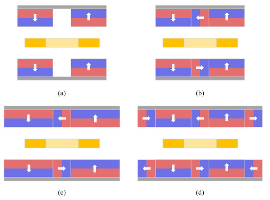
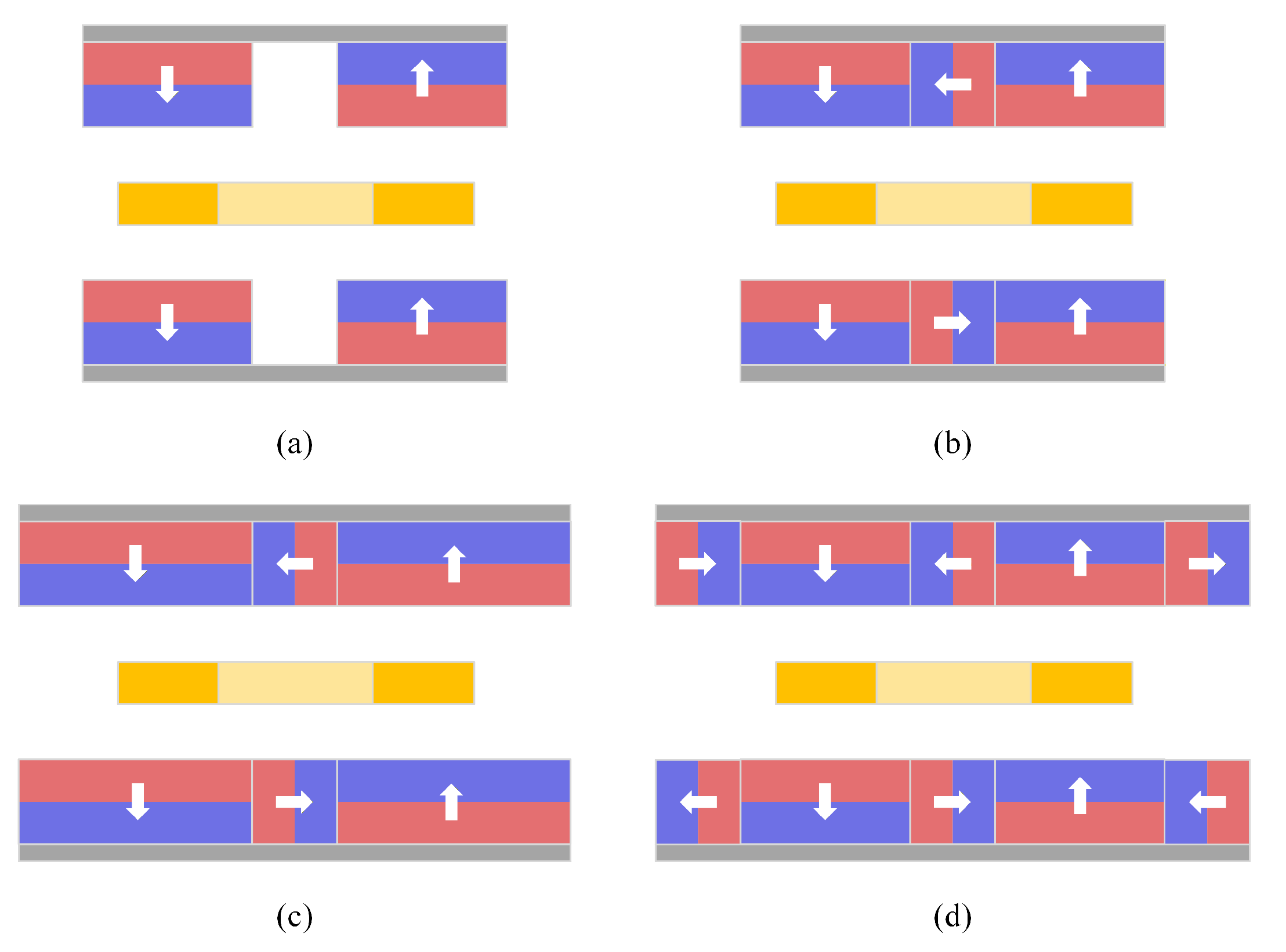
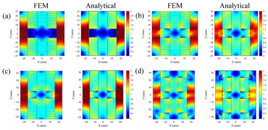
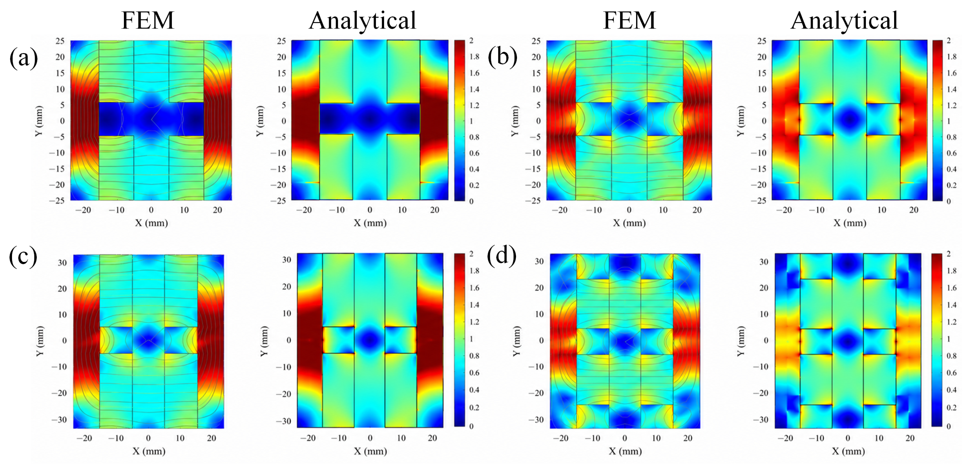
In order to determine an optimal array configuration, the magnetic field distribution and associated actuation performance of four different magnet array configurations are investigated. As shown in Figure 9, the conventional NS array only has two magnets on each side with heteropolar orientations. Both consisted of three magnets with sequential rotated orientations on each side: the simplified Halbach array has side magnets with 20 mm width and the extended Halbach array has side magnets with 30 mm width. The full Halbach array has the same array length as the extended Halbach array but with a sequence of five permanent magnets. Figure 10 plots the magnetic field distribution of the four array configurations with both COMSOL-based FEM and the proposed analytical method. The results obtained by the two methods are in good agreement, demonstrating the legitimacy of the proposed analytical method.
Figure 9.
Schematic diagram of different arrays: (a) general NS array, (b) simplified Halbach array, (c) extended Halbach array, (d) full Halbach array.
Figure 10.
Magnetic field analysis for different magnet arrays based on different simulation schemes: (a) conventional NS array; (b) simplified Halbach array; (c) extended Halbach array; (d) full Halbach array.
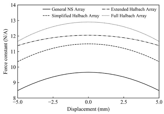
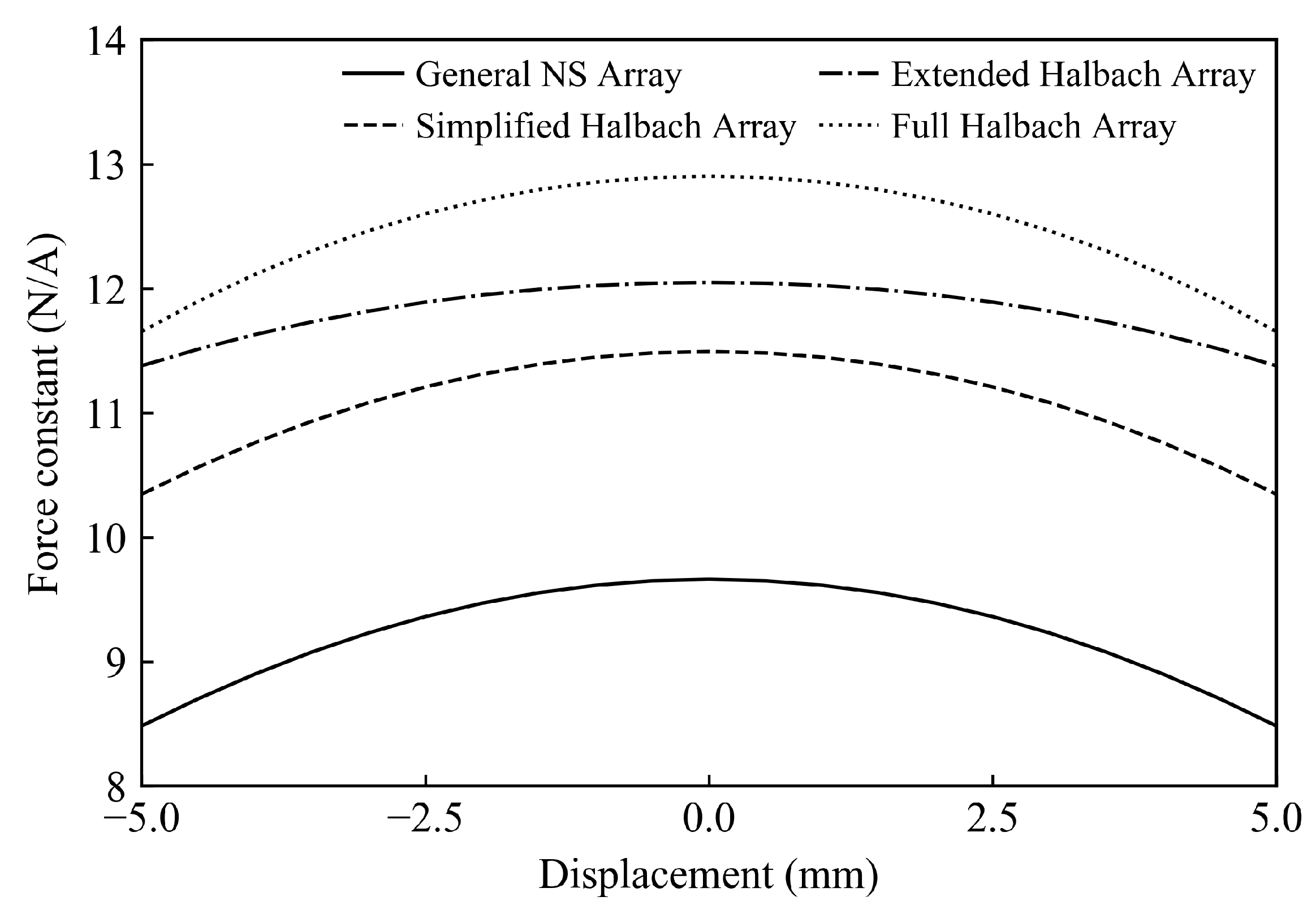
With the analytical method, the force constants along the actuation direction of the four configurations are calculated and compared, as shown in Figure 11. It is shown that the conventional NS array, simplified Halbach array, extended Halbach array, and full Halbach array have nominal force constants of 9.66, 11.49, 12.05, and 12.90 N/A at the central position, respectively. Therefore, the simplified Halbach array improves the nominal force constant by 18.9% compared with the conventional NS array, confirming the benefit of adopting the Halbach magnetization pattern for air gap flux concentration. Over the scanned displacement range of mm, the mean force constants of the four configurations are 9.23, 11.07, 11.81, and 12.45 N/A, respectively. The full Halbach array gives the largest force output, but its nominal and mean force constants are only 12.3% and 12.4% higher than those of the simplified Halbach array, while requiring a longer and more complex magnet arrangement. The extended Halbach array provides only a 6.7% higher mean force constant than the simplified Halbach array and has a slightly lower nominal force constant at the central position, but its magnet array length is 40% larger. The simplified Halbach array achieves a clear force-density improvement over the traditional NS array while maintaining almost the same near-center performance as the extended array within a shorter magnet length. Those features make it more suitable for the thickness-limited and volume-constrained spacecraft application considered in this study.
Figure 11.
Comparison of the relationship between displacement on the force action line and force constant coefficient for different arrays.
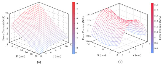
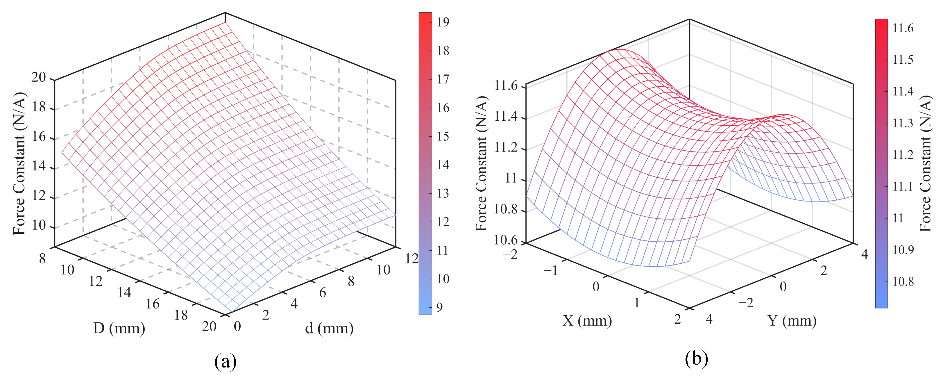
Figure 12 shows the influence of the back yoke thickness, the magnet array gap size and the coil position on the force constant. As shown in Figure 12a, the force constant increases as the gap size of the magnet array decreases and the back yoke thickness increases. However, to ensure non-contact operation, the gap size of the magnet array is constrained by the platform movement and the thickness of the coil. In addition, it can be observed that when the thickness of the back yoke increases to more than , the growth rate of the force constant decreases significantly.
Figure 12.
Force constant coefficient analysis of the optimized Halbach actuator: (a) effects of the magnet array gap and back-iron thickness; (b) force constant coefficient at different coil positions.
Based on the optimized parameters, the force constant of the actuator coil at different positions can be obtained, as shown in Figure 12b. It can be found that the distribution of the force constant is generally saddle-shaped, with the coil closer to the magnet experiencing a greater force intensity, while moving along the direction of the actuator’s movement will lead to a decrease in the force constant. This nonlinearity of the distribution makes the controller design difficult, but the model we provide can effectively simulate the position-dependent force constant and supply a physically informed initial value for secondary path modeling in the FxLMS algorithm.
5. Active Control Strategy Design
The active vibration isolation platform needs an effective and robust control law to achieve the desired vibration isolation performance. Micro-vibration response of a real satellite is usually hybrid, which consists not only of broadband noise but also a pronounced discrete spectrum. The discrete spectrum is caused by the complicated vibration modes of the satellite structure, possessing much higher vibration energy. Suppression of the discrete spectrum is crucial to the stability and precision of the satellite. Since the actuation coil induces a back EMF that depends on the position and velocity of the actuation coil, a conventional fixed-gain PID controller may not maintain satisfactory performance when the isolation platform is subject to broadband disturbance. To address these challenges, an FxLMS-based adaptive feedforward controller with a physically informed initial state estimation is adopted here. The analytical electromagnetic model developed in Section 3 is used to give an initial estimation of the secondary path for better convergence and accuracy.
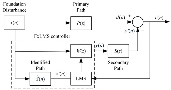
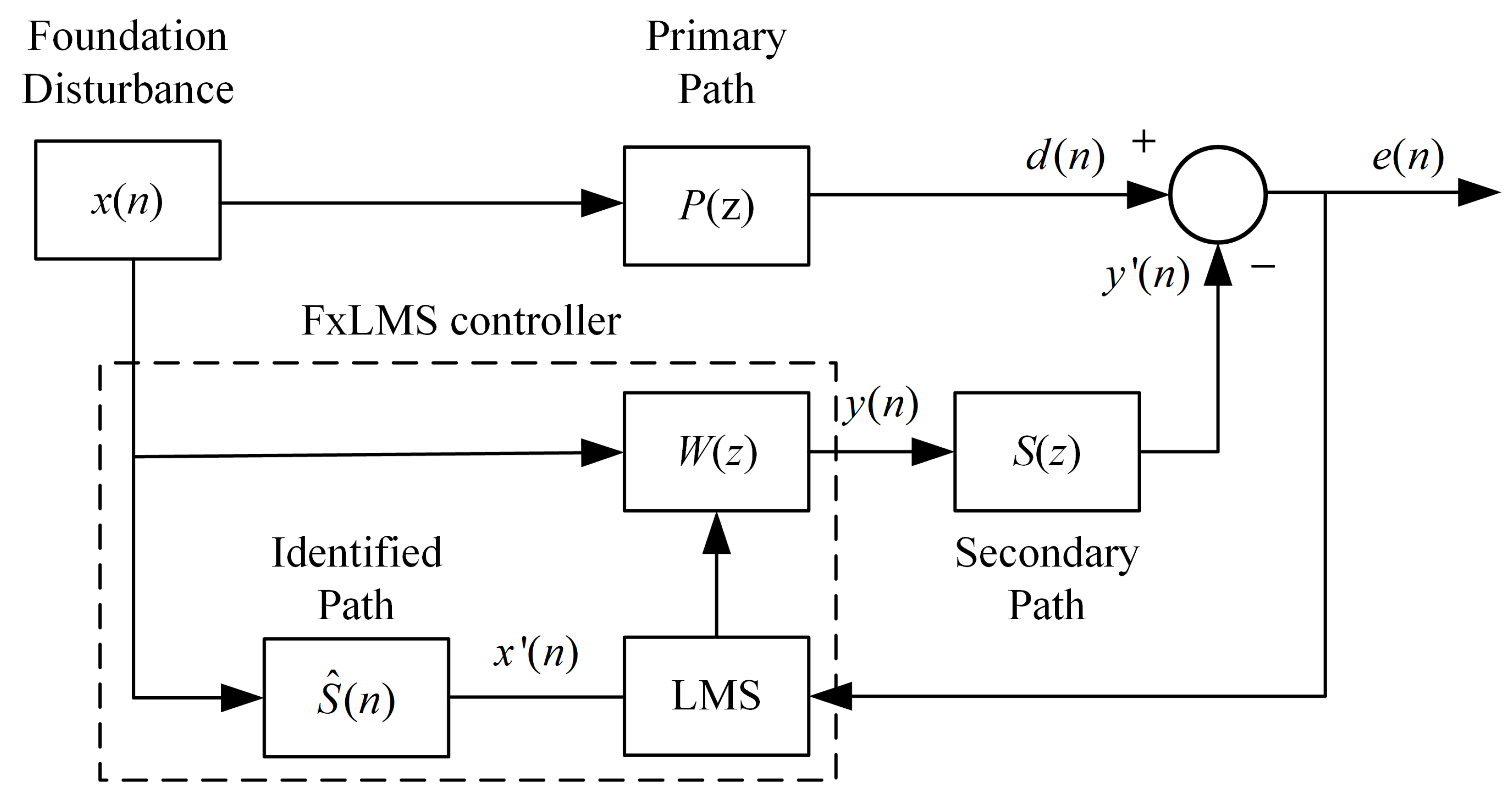
The block diagram of the FxLMS-based feedforward control system is shown in Figure 13. For this vibration isolation platform, the reference signal denotes the disturbance subject to the base foundation and the error signal is the acceleration of the payload platform. The primary path represents the vibration transmission path from the foundation disturbance to the payload platform without active control, while the secondary path describes the transmission from the controller output to the platform response, including the actuator dynamics, platform dynamics, and electrical dynamics of sensing. With a feedforward command signal generated by the FxLMS controller, marked with dashed lines in Figure 13, the actuator shall output an actively controlled actuation force that cancels the vibration response of the platform caused by the foundation disturbance.
Figure 13.
Block diagram of the FxLMS-based feedforward controller.
Let denote the Lth-order controller weight vector at discrete time n, where L is the controller filter length in taps, and let denote the corresponding reference signal vector. The control output is determined as
The voltage command is transmitted to the platform through the secondary path, which is usually assumed as a finite-duration impulse response (FIR) system of length M, where M denotes the number of taps used for secondary path modeling, with its weight vector defined as
Accordingly, the error signal at the payload platform is expressed in the form of
where denotes the primary disturbance.
In order to compensate the error on the payload platform, the reference signal is filtered through an estimate secondary path filter and used to update the controller weight vector. The filtered signal is determined as
and the controller weight vector is then updated by the stochastic-gradient rule of the FxLMS algorithm as
with being the step size.
The analytical actuator model is used to provide a physics-informed initial estimate of the secondary path before the experimental white-noise refinement. Based on the argument of Section 3, an initial voltage-to-acceleration model from the controller output y to the measured error acceleration is constructed.
where is the power-amplifier gain, is the back-EMF coefficient, is the force constant, is the payload displacement along the controlled direction, and m, c, and k denote the equivalent mass, damping, and stiffness of the SDOF isolation platform, respectively. Equation (25) gives an initial continuous-time secondary path model as
where and denote the Laplace transforms of the controller output voltage and the payload displacement, respectively. After discretization, the impulse response of is truncated to the FIR length M and used as the initial secondary path vector
where are the first M samples of the impulse response of . This initialization provides a physically reasonable starting point, while the subsequent white-noise identification refines to compensate for unmodeled amplifier dynamics, sensor dynamics, structural damping, and data-acquisition delay.
6. Active Vibration Isolation Experiment
With the developed Halbach array actuator, a single-degree-of-freedom vibration isolation experimental system is built and used to verify the active vibration control performance.
It is worth mentioning that the real in-orbit micro-vibration has an extremely small amplitude at the level of g, which is very difficult to replicate in the on-ground environment. Thus, in this experimental verification, the purpose is to verify the relative vibration suppression capability of the active vibration isolation platform.
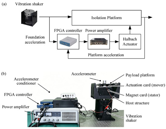
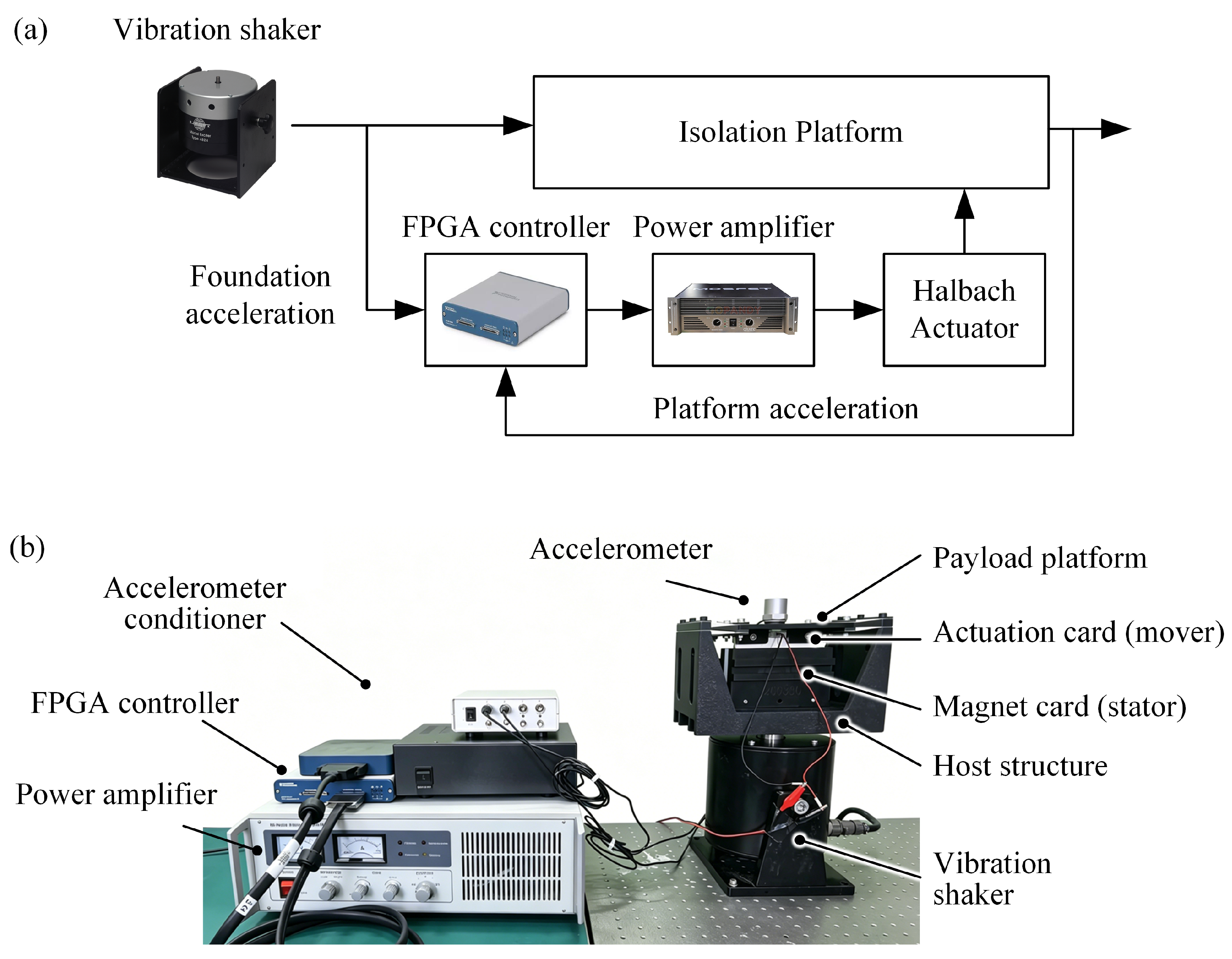
Figure 14a shows the schematic of the active vibration isolation system. The isolation system is subject to a foundation disturbance via a vibration shaker. Accelerations of the base foundation and the payload platform are fed into the FPGA controller where the FxLMS-based control algorithm determines the control command. The FxLMS algorithm is implemented on the NI USB-7855R FPGA controller with a sampling frequency of 2 kHz (ten times the maximum control frequency). The algorithm is programmed in the LabVIEW 2021 graphical programming environment, where the discrete-time update law in Equation (24) is executed iteratively in a timed loop. The control command is amplified via a power amplifier and drives the Halbach actuator to produce the cancelation actuation force. Figure 14b illustrates the experimental apparatus of the test system, which is composed of a NI USB-7855R FPGA controller, an accelerometer conditioner, a power amplifier (SP-PA020), a vibration shaker (SA-JZ020) and the proposed single-DOF vibration isolator. The vibration isolator has three major components: a payload platform, a host foundation, and the Halbach array actuator. The stator of the actuator is mounted on the host foundation structure that is screwed to the shaker and the mover of the actuator is assembled to the payload platform. Two accelerometers are attached to the payload platform and the host structure, measuring the vibration acceleration responses. The acceleration response of the host structure is the reference signal and that of the payload platform is the error signal.
Figure 14.
Experimental setup of the single-DOF magnetic levitation vibration isolation system: (a) schematic of the vibration isolation system; (b) photograph of the test apparatus.
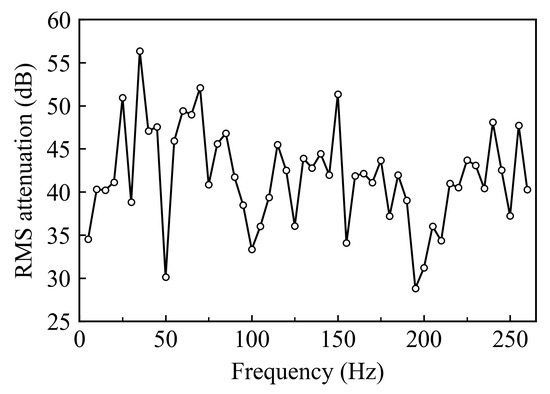
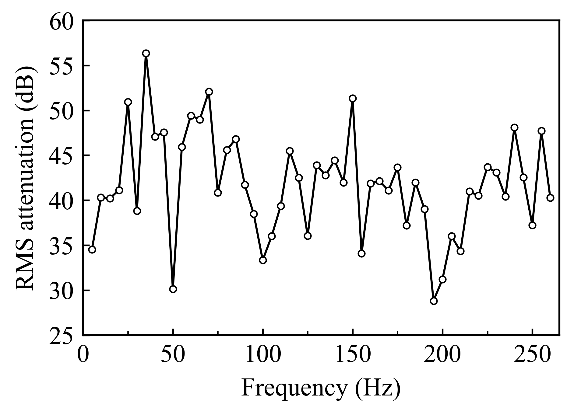
In the experiment, the vibration shaker is excited with fixed frequency voltage input. The vibration responses of the platform with and without active control are measured respectively. We measured the vibration suppression at every 5 Hz from 5 to 260 Hz, and the results are plotted in Figure 15. The suppression levels at selected frequencies (5, 10, 15, 20, 30, 50, 75, 100, 125, 150, 200, and 250 Hz) are also listed in Table 3 for clarity. As shown in the table, the active vibration isolation platform can achieve over 35 dB vibration suppression within a frequency range between 5 Hz and 250 Hz. It has a maximum vibration suppression of 51.35 dB with excitation frequency at 150 Hz and a minimum 30.12 dB suppression at 50 Hz. To evaluate the overall broadband isolation performance, we adopt the arithmetic mean of the suppression levels over all measured frequencies. Since the frequencies are uniformly sampled, the mean suppression performance serves as a reasonable indicator of the average attenuation across the frequency band. With the developed active vibration isolation platform, the average vibration suppression reaches 41.73 dB.
Figure 15.
Vibration suppression versus excitation frequency from 5 to 260 Hz with a step of 5 Hz.
Table 3.
Vibration suppression performance with various excitation frequencies.
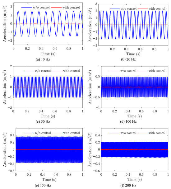
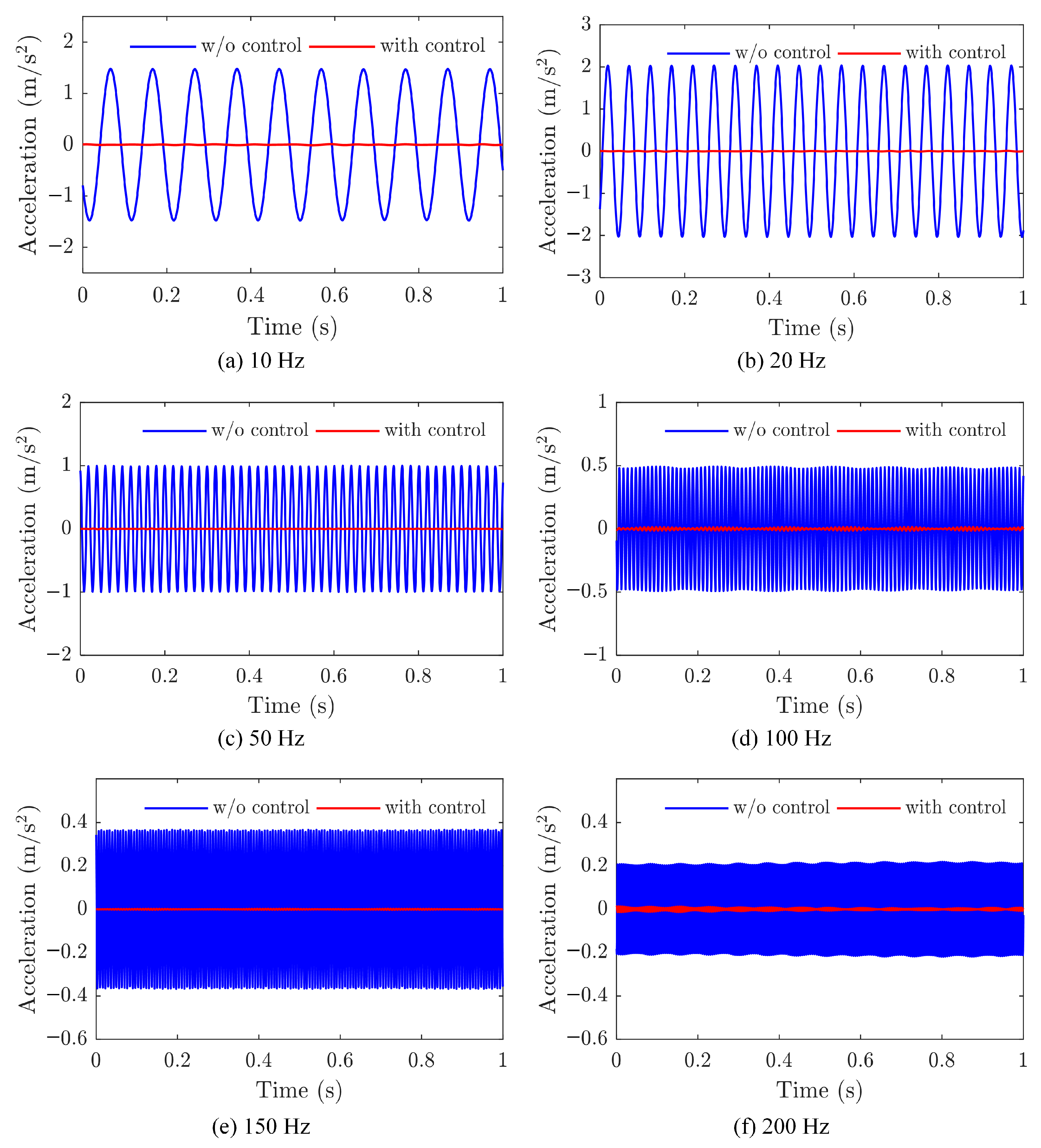
Figure 16 plots the time histories of the uncontrolled and controlled vibrational accelerations of the platform at 10, 20, 50, 100, 150, and 200 Hz respectively. The time histories of acceleration responses with and without active control also demonstrate the vibration isolation capability of the proposed active vibration isolation platform.
Figure 16.
Active vibration isolation experiment results with excitation frequencies of: (a) 10 Hz, (b) 20 Hz, (c) 50 Hz, (d) 100 Hz, (e) 150 Hz, and (f) 200 Hz.
7. Conclusions
This paper proposed a slim magnetically levitated actuator based on modified Halbach bi-arrays. An analytical electromagnetic model was developed via infinitesimal current-element integration and an iterative back-iron magnetization scheme to provide accurate and efficient prediction of the magnetic field distribution, back EMF, and thrust force constant of the actuator. With the proposed Halbach array actuator, a single-degree-of-freedom active vibration isolation platform is developed. The platform is actively actuated by the non-contact levitated actuator via an adaptive control strategy. The control strategy is built based on a physically augmented FxLMS algorithm wherein the secondary path identification is initialized with an analytical estimate of the dynamic response of the actuator.
The active vibration isolation experiment has validated the vibration isolation capability of the single-DOF vibration isolation platform. With the foundation subject to vertical harmonic excitations, the active vibration isolation platform achieved significant vibration isolation performance with an average 41.73 dB vibration suppression. The verification experiment has covered a broad frequency range from 5 Hz to 260 Hz which locates within the major micro-vibration bandwidth of spacecraft and small satellites. Meanwhile, the Halbach array actuator produces a 11.78 N/A thrust force constant with the nonlinearity less than 0.5%. The developed Halbach array actuator and the associated single-DOF vibration isolation platform have demonstrated very promising potential in resolving the micro-vibration control problems of small spacecraft and satellites. The current work focuses on the SDOF platform to validate the proposed actuator and control strategy in a controlled setting; multi-DOF coupling and higher-order dynamics are beyond the scope of this paper and will be addressed in future developments. The proposed actuator and control framework are expected to be scalable to multi-DOF systems, with the realization of a multi-DOF micro-vibration isolation system left for future investigation.
Author Contributions
Conceptualization, H.G.; methodology, Z.H.; software, Z.H.; validation, Z.H., Z.Q. and X.Y.; formal analysis, M.Z. and Z.H.; investigation, Z.Q.; resources, M.Z.; data curation, Z.Q.; writing—original draft preparation, Z.H.; writing—review and editing, H.G.; visualization, Z.H. and Z.Q.; supervision, H.G.; project administration, H.L.; funding acquisition, L.Z. All authors have read and agreed to the published version of the manuscript.
Funding
This research was funded by Shanghai Municipal Science and Techonology Major Project (Grant No.2019SHZDZX01).
Data Availability Statement
Dataset available on request from the authors.
Conflicts of Interest
The authors declare no conflicts of interest. The funders had no role in the design of the study; in the collection, analyses, or interpretation of data; in the writing of the manuscript; or in the decision to publish the results.
Appendix A. Analytical Expressions for the Double Integral of B over a Rectangular Coil
The double integral of the x-component of the magnetic flux density over a rectangular coil region is presented below for two magnetization directions. The rectangular coil has side length in the x-direction and side length in the y-direction. Its center is located at relative to the magnet center. The permanent magnet has width w in the x-direction and height h in the y-direction, with magnetization strength M in A/m. The vacuum permeability is H/m.
The integration limits of the coil are
Appendix A.1. Magnetization Along the y-Direction
The integral can be expressed as
where
and the parameter pairs are
The auxiliary function is defined as
Appendix A.2. Magnetization Along the x-Direction
Similarly, for x-direction magnetization,
with
and the parameter pairs
The auxiliary function is defined as
References
- Yuan, Z.; Zhang, Z.; Zeng, L.; Li, X. Microvibration isolation in sensitive payloads: Methodology and design. Nonlinear Dyn. 2023, 111, 19563–19611. [Google Scholar] [CrossRef] [Scilit]
- Foster, C.L.; Tinker, M.L.; Nurre, G.S.; Till, W.A. Solar-array-induced disturbance of the Hubble space telescope pointing system. J. Spacecr. Rocket. 1995, 32, 634–644. [Google Scholar] [CrossRef] [Scilit] [PubMed]
- Feng, H.M.; Cao, Z.H.; Lam, M.I.; Li, R.; Tian, H.; Zhang, X.; Wei, P.; Li, X.F.; Wang, W.; Jones, H.R.; et al. The Velocity Aberration Effect of the CSST Main Survey Camera. Res. Astron. Astrophys. 2024, 24, 095010. [Google Scholar] [CrossRef] [Scilit]
- Luo, J.; Chen, L.S.; Duan, H.Z.; Gong, Y.G.; Hu, S.; Ji, J.; Liu, Q.; Mei, J.; Milyukov, V.; Sazhin, M.; et al. TianQin: A space-borne gravitational wave detector. Class. Quantum Gravity 2016, 33, 035010. [Google Scholar] [CrossRef] [Scilit]
- Liu, C.; Jing, X.; Daley, S.; Li, F. Recent advances in micro-vibration isolation. Mech. Syst. Signal Process. 2015, 56, 55–80. [Google Scholar] [CrossRef] [Scilit]
- Li, D.; Liu, W. Vibration control for the solar panels of spacecraft: Innovation methods and potential approaches. Int. J. Mech. Syst. Dyn. 2023, 3, 300–330. [Google Scholar] [CrossRef] [Scilit]
- Zhang, Z.; Aglietti, G.S.; Zhou, W. Microvibrations induced by a cantilevered wheel assembly with a soft-suspension system. AIAA J. 2011, 49, 1067–1079. [Google Scholar] [CrossRef] [Scilit]
- Vaillon, L.; Philippe, C. Passive and active microvibration control for very high pointing accuracy space systems. Smart Mater. Struct. 1999, 8, 719–728. [Google Scholar] [CrossRef] [Scilit]
- Ibrahim, R. Recent advances in nonlinear passive vibration isolators. J. Sound Vib. 2008, 314, 371–452. [Google Scholar] [CrossRef] [Scilit]
- Jiao, X.; Zhang, J.; Li, W.; Wang, Y.; Ma, W.; Zhao, Y. Advances in spacecraft micro-vibration suppression methods. Prog. Aerosp. Sci. 2023, 138, 100898. [Google Scholar] [CrossRef] [Scilit]
- Shi, H.T.; Abubakar, M.; Bai, X.; Luo, Z. Vibration isolation methods in spacecraft: A review of current techniques. Adv. Space Res. 2024, 73, 3993–4023. [Google Scholar] [CrossRef] [Scilit]
- Onoda, J.; Oh, H.U.; Minesugi, K. Improved electrorheological-fluid variable damper designed for semiactive vibration suppression. AIAA J. 2000, 38, 1736–1741. [Google Scholar] [CrossRef] [Scilit] [PubMed]
- Zhu, X.; Jing, X.; Cheng, L. Systematic design of a magneto-rheological fluid embedded pneumatic vibration isolator subject to practical constraints. Smart Mater. Struct. 2012, 21, 035006. [Google Scholar] [CrossRef] [Scilit]
- Wang, X.; Wu, H.; Yang, B. Micro-vibration suppressing using electromagnetic absorber and magnetostrictive isolator combined platform. Mech. Syst. Signal Process. 2020, 139, 106606. [Google Scholar] [CrossRef] [Scilit]
- Ma, Z.; Zhou, R.; Yang, Q.; Lee, H.P.; Chai, K. A Semi-Active Electromagnetic Quasi-Zero-Stiffness Vibration Isolator. Int. J. Mech. Sci. 2023, 252, 108357. [Google Scholar] [CrossRef] [Scilit]
- Yuan, Z.; Zhang, Z.; Zeng, L.; Zhu, L.; Li, X. Micropositioning and Microvibration Isolation of a Novel Hybrid Active–Passive Platform with Two-Axis Actuator for Optical Payloads. Mech. Syst. Signal Process. 2023, 204, 110764. [Google Scholar] [CrossRef] [Scilit]
- He, Z.; Feng, X.; Zhu, Y.; Yu, Z.; Li, Z.; Zhang, Y.; Wang, Y.; Wang, P.; Zhao, L. Progress of Stewart Vibration Platform in Aerospace Micro–Vibration Control. Aerospace 2022, 9, 324. [Google Scholar] [CrossRef] [Scilit]
- Hui, Y.; Fan, Y.; Luo, R. Modeling and Control of Two-Stage Magnetically Suspended Rotating Payload Platform. Adv. Space Res. 2024, 74, 1706–1723. [Google Scholar] [CrossRef] [Scilit]
- Chen, F.; Wang, W.; Wang, S. Rotating Lorentz Force Magnetic Bearings’ Dynamics Modeling and Adaptive Controller Design. Sensors 2023, 23, 8543. [Google Scholar] [CrossRef] [Scilit] [PubMed]
- Zhao, X.; Geng, Y.; Yi, T.; Yuan, C.; Wu, B. Dynamics and Adaptive Backstepping Control of Multibody Spacecraft Connected with Active Magnetic Bearing. Proc. Inst. Mech. Eng. Part G J. Aerosp. Eng. 2022, 236, 2508–2522. [Google Scholar] [CrossRef] [Scilit]
- Yang, F.; Zhao, Y.; Mu, X.; Zhang, W.; Jiang, L.; Yue, H.; Liu, R. A Novel 2-DOF Lorentz Force Actuator for the Modular Magnetic Suspension Platform. Sensors 2020, 20, 4365. [Google Scholar] [CrossRef] [Scilit] [PubMed]
- Kim, M.H.; Kim, H.Y.; Kim, H.C.; Ahn, D.; Gweon, D.G. Design and Control of a 6-DOF Active Vibration Isolation System Using a Halbach Magnet Array. IEEE/ASME Trans. Mechatron. 2016, 21, 2185–2196. [Google Scholar] [CrossRef] [Scilit]
- Hong, D.K.; Park, J.H. Electromagnetic Design and Analysis of Inertial Mass Linear Actuator for Active Vibration Isolation System. Actuators 2023, 12, 295. [Google Scholar] [CrossRef] [Scilit]
- Meng, X.; Wang, C.; Zhong, J.; Xia, H.; Song, L.; Yang, G. Research on Magnetic Field and Force Characteristics of a Novel Four-Quadrant Lorentz Force Motor. Energies 2023, 16, 1091. [Google Scholar] [CrossRef] [Scilit]
- Yuan, Z. Two-Axis Lorentz Actuator for Active Vibration Isolation System in Optical Payloads. Mech. Syst. Signal Process. 2024, 219, 111614. [Google Scholar] [CrossRef] [Scilit]
- Jiao, Z.; Wang, T.; Yan, L. Design of a Tubular Linear Oscillating Motor With a Novel Compound Halbach Magnet Array. IEEE/ASME Trans. Mechatron. 2017, 22, 498–508. [Google Scholar] [CrossRef] [Scilit]
- Kim, M.; Jeong, J.H. A Dual-Servo Stage With 6 D.O.F. Magnetically Levitated Fine Stage. IEEE Access 2025, 13, 67366–67377. [Google Scholar] [CrossRef] [Scilit]
- Jansen, J.W.; Van Lierop, C.M.M.; Lomonova, E.A.; Vandenput, A.J.A. Modeling of Magnetically Levitated Planar Actuators With Moving Magnets. IEEE Trans. Magn. 2007, 43, 15–25. [Google Scholar] [CrossRef] [Scilit]
- Li, J.; Zeng, S.; Guo, Q.; Zhong, S.; Liang, W.; He, W. Modeling of a Six-Degree-of-Freedom Magnetic Levitation Platform Actuated by Noncontact Lorentz Forces. J. Vib. Control 2025, 31, 3383–3397. [Google Scholar] [CrossRef] [Scilit]
- Senoner, D. Development of a Hybrid Reluctance-Actuated Stewart Platform. Diploma Thesis, Technische Universität Wien, Vienna, Austria, 2024. [Google Scholar]
- Chen, Y.; Zhang, K. Analytic calculation of the magnetic field created by Halbach permanent magnets array. J. Magn. Mater. Devices 2014, 9, 1–4. [Google Scholar] [CrossRef] [Scilit]
- Lee, M.G.; Lee, S.Q.; Gweon, D.G. Analysis of Halbach Magnet Array and Its Application to Linear Motor. Mechatronics 2004, 14, 115–128. [Google Scholar] [CrossRef] [Scilit]
- Curti, M.; Paulides, J.J.; Lomonova, E.A. An overview of analytical methods for magnetic field computation. In Proceedings of the 2015 Tenth International Conference on Ecological Vehicles and Renewable Energies (EVER); IEEE: Piscataway, NJ, USA, 2015; pp. 1–7. [Google Scholar]

Disclaimer/Publisher’s Note: The statements, opinions and data contained in all publications are solely those of the individual author(s) and contributor(s) and not of MDPI and/or the editor(s). MDPI and/or the editor(s) disclaim responsibility for any injury to people or property resulting from any ideas, methods, instructions or products referred to in the content. |
© 2026 by the authors. Licensee MDPI, Basel, Switzerland. This article is an open access article distributed under the terms and conditions of the Creative Commons Attribution (CC BY) license.