


Abstract
This study examines how the rotational stiffness of two wingtip interfaces changes the low-frequency aeroelastic response of a free–free, three-module unmanned aerial vehicle. A finite-element model coupled with doublet-lattice aerodynamics is analyzed using the p–k method. The response associated with the lowest retained oscillatory crossing of the locked reference is followed along single-channel and prescribed multi-channel stiffness paths using complex-eigenvector modal assurance criteria. Competing crossings and discrete unequal-interface cases are reported separately. Rotation about the spanwise joint axis (DOF 5) produces the largest target migration, from approximately 11.7 to 31.7 m/s; the other two channels affect this target less, although DOF 4 can introduce a lower-speed competing response. Unequal-interface cases change candidate ordering without establishing a universal asymmetry law. A five-case Nastran–ZAERO comparison reproduces the selected stiffness trends, with an approximately 10.2% difference in low-frequency crossing speeds. The contribution is a comparison of channel-dependent target migration and candidate competition under common modeling assumptions. The results constitute a branch-specific numerical sensitivity analysis under linear, zero-structural-damping assumptions; they do not establish a global or experimentally validated flutter boundary.
1. Introduction
High-altitude long-endurance aircraft and long-endurance unmanned aerial vehicles (UAVs) obtain much of their aerodynamic efficiency from lightweight, high-aspect-ratio lifting surfaces. The same design choices lower structural frequencies and reduce the separation between flight-dynamic and elastic time scales, so aeroelastic stability must be considered while the configuration and its load paths are being defined [1,2]. Wingtip-connected modular aircraft pursue a related objective by assembling several smaller vehicles into a larger effective lifting system: individual units can operate independently for distributed missions and connect when a larger span or reconfigured payload architecture is advantageous [3,4]. The connection is, therefore, more than a docking fixture. Its stiffness controls local load transfer and relative motion and can reorganize the low-frequency elastic content that participates in aeroelastic instability.
Research on connected aircraft has established the dynamical importance of the interface, but has mainly addressed flight mechanics, docking, and control. The meta-aircraft formulation of Montalvo and Costello showed that joint stiffness and damping govern additional relative roll, pitch, and yaw modes [4]. Subsequent wingtip-docking studies demonstrated that connection forces, joint elements, and close-proximity aerodynamic effects enter the coupled dynamics during and after capture [5]. Flight and ground experiments further showed that joint-induced relative modes can make an uncontrolled connected configuration difficult to operate and that feedback stabilization is central to sustained connected flight [6,7]. For three-unit aircraft, Zhu et al. separated symmetric and asymmetric modal groups and identified interactions between relative roll motion and modes inherited from an individual aircraft [8]; complementary aerodynamic modeling has shown that layout parameters also affect the trim and stability of wingtip-hinged multibody aircraft [9]. These studies motivate, but do not resolve, the aeroelastic sensitivity of a two-interface configuration to individual and combined rotational stiffness channels.
Folding-wing research provides useful evidence that a localized rotational connection can materially change aeroelastic behavior. Theoretical and experimental studies have demonstrated sensitivity to hinge stiffness, fold angle, and local structural properties [10,11]. More recently, Qi, Wu, and Tian used a non-intrusive model with the p–k method to study a modified Z-shaped folding wing, further illustrating that hinge-related parameters can alter flutter characteristics [12]. Experiments and calculations for folding fins with asymmetric free-play also show how realistic joint behavior can introduce nonlinear and unequal responses [13], while adjacent-wing studies establish that aerodynamic proximity can modify system stability [14]. These are physical analogies rather than dynamically equivalent models. Each unit of the present modular UAV retains its own distributed mass, inertia, wing, and tail; the assembled system contains two spatially separated interfaces and three rotational channels at each interface. Consequently, it can support symmetric and antisymmetric relative motions, prescribed multi-channel co-variation, and left–right inequality that cannot be represented by a single-hinge model.
For linear subsonic analysis, the doublet-lattice method and the p–k solution provide established frequency-domain descriptions of unsteady aerodynamic loading and modal damping [15,16]. A parameter sweep nevertheless need not yield one unambiguous sequence of critical roots. Several oscillatory candidates can approach zero damping within a single stiffness case, and their frequencies and solver ordering can change as stiffness varies. Mode order or nearest frequency alone is, therefore, insufficient to establish physical modal identity [17,18]. Eigenvector-based association and controlled backtracking have been developed because non-self-adjoint aeroelastic eigenproblems can defeat simple matching near closely spaced roots or parameter-induced reordering [18,19]. Adaptive-continuation work likewise shows the value of local sampling near closely competing or zero-damping regions [20]. The present analysis, therefore, extracts comparable complex aeroelastic eigenvectors on a fixed physical grid and uses modal assurance criteria (MAC) to validate the modal identity of a scalar-screened, locked-reference-oriented candidate path. Other supported zero-damping candidates are retained as a competition audit.
The structural model is free–free: no artificial support is imposed, and the six global rigid-body modes remain in the modal reduction. Following the conventional structural-flutter treatment adopted here, these non-oscillatory roots are excluded from the reported candidate set so that the analysis focuses on elastic and connection-related responses. The analysis uses an undeformed reference configuration without trim equations or explicit flight-dynamic states, distinct from a body-freedom-flutter formulation [1,21]. Fully released interfaces can additionally introduce internal near-zero relative-rotation mechanisms; finite rotational stiffness elevates them into low-frequency connection modes. In the conventional locked configuration, the branch-7 contact near 2.4 Hz is the lowest retained oscillatory zero-damping crossing and, therefore, defines the physical response of interest. The purpose of the stiffness paths is to follow the evolution of this same mechanism, even when a different crossing appears at a lower speed in an individual modified configuration. The locked response orients the candidate screen, while modal identity is assessed along each stiffness path. Complex-eigenvector MAC subsequently validates adjacent modal identity and triggers local reassociation when a screened proposal fails. Other supported candidates are reported separately to reveal competition with the MAC-validated target.
The unresolved problem is consequently specific: how do two parameterized interfaces redistribute the selected low-frequency aeroelastic response of a free–free three-unit modular UAV? Unlike a single-hinge study, the present configuration permits comparison of three rotational channels, prescribed two- and three-channel co-variation paths, and discrete unequal left–right cases under one finite-element–doublet-lattice–p–k model. The following research questions are addressed:
- Are the adopted modal basis, local velocity sampling, and reduced-frequency sampling adequate for the locked-reference low-frequency target response?
- How do symmetric single-channel and prescribed multi-channel stiffness variations change the target zero-damping candidate, and when does the lowest-speed retained candidate indicate competition from another mechanism?
- How do the investigated unequal left–right interface cases alter the target response and candidate ordering relative to the symmetric, released, and locked references?
This paper makes three contributions. First, it formulates a free–free, three-unit aeroelastic model with two independently parameterized interfaces and a consistent definition of rotational DOFs 4–6. Second, it evaluates symmetric single-channel sweeps, prescribed multi-channel paths, released and locked references, and discrete unequal-interface cases within a common analysis framework. Third, it combines scalar zero-damping screening with adjacent complex-MAC validation, reporting the resulting low-frequency MAC-validated target path separately from other supported candidates. This distinguishes target migration from candidate competition and exposes solver-order changes that would otherwise appear as branch discontinuities. Numerical-setting checks are tailored to the monitored low-frequency response.
The scope is a linear small-disturbance model about an undeformed, unloaded reference configuration, with zero structural damping, fixed flight parameters, and prescribed stiffness paths. The active joint rotations have finite stiffness, while translations and inactive rotations remain constrained. Section 4.7 collects the omitted physical effects and the resulting interpretation limits. The study provides a branch-specific numerical stiffness-sensitivity map, supported by modal-association checks and a selected cross-solver comparison.
Section 2 defines the structural model, interface parameterization, aerodynamic coupling, and p–k extraction framework. Section 3 assesses the numerical settings and establishes the locked-reference response. Section 4 presents the single-channel, multi-channel, released/locked, and unequal-interface results; the final section summarizes the principal findings and limitations.
2. Aeroelastic Model and Analysis Procedure
2.1. Configuration, Coordinates, and Model Definition
The configuration consists of three identical fixed-wing unmanned aerial vehicles (UAVs) connected wingtip-to-wingtip through two rotationally parameterized interfaces. The middle UAV is the reference unit; the interfaces on its port and starboard sides are denoted by and , respectively (Figure 1a). The three modules are arranged side by side, with parallel longitudinal axes and their main-wing and horizontal-tail aerodynamic reference surfaces in a common plane. Each module has the same three-dimensional structural arrangement shown in Figure 1b: a main wing with ribs and longitudinal load-carrying members, a longitudinal fuselage representation, and an aft horizontal tail. The assembled main-wing span is 3.650 m; the main-wing chord and overall longitudinal length of each module are 0.200 and 0.620 m, respectively.
The main-wing structural contour follows the symmetric NACA 0021 section, with a nominal thickness-to-chord ratio of 0.21 (Figure 1c). This designation was checked against the finite-element section coordinates. The horizontal tail is represented by a rectangular planar model with a lifting-surface span of 0.560 m and a chord of 0.080 m; the available model does not establish a named physical tail airfoil. These structural views complement the planar aerodynamic layout in panel (a). All input decks use the N–mm–s–tonne unit system. Table 1 and Table 2 record the geometry, mass properties, materials, and structural and aerodynamic discretizations extracted from the locked baseline deck.
Table 1.
Baseline geometry and mass properties extracted from the locked input deck. Assembly moments of inertia are about the center of gravity and resolved in .
Table 2.
Structural and aerodynamic idealization of the locked baseline model.
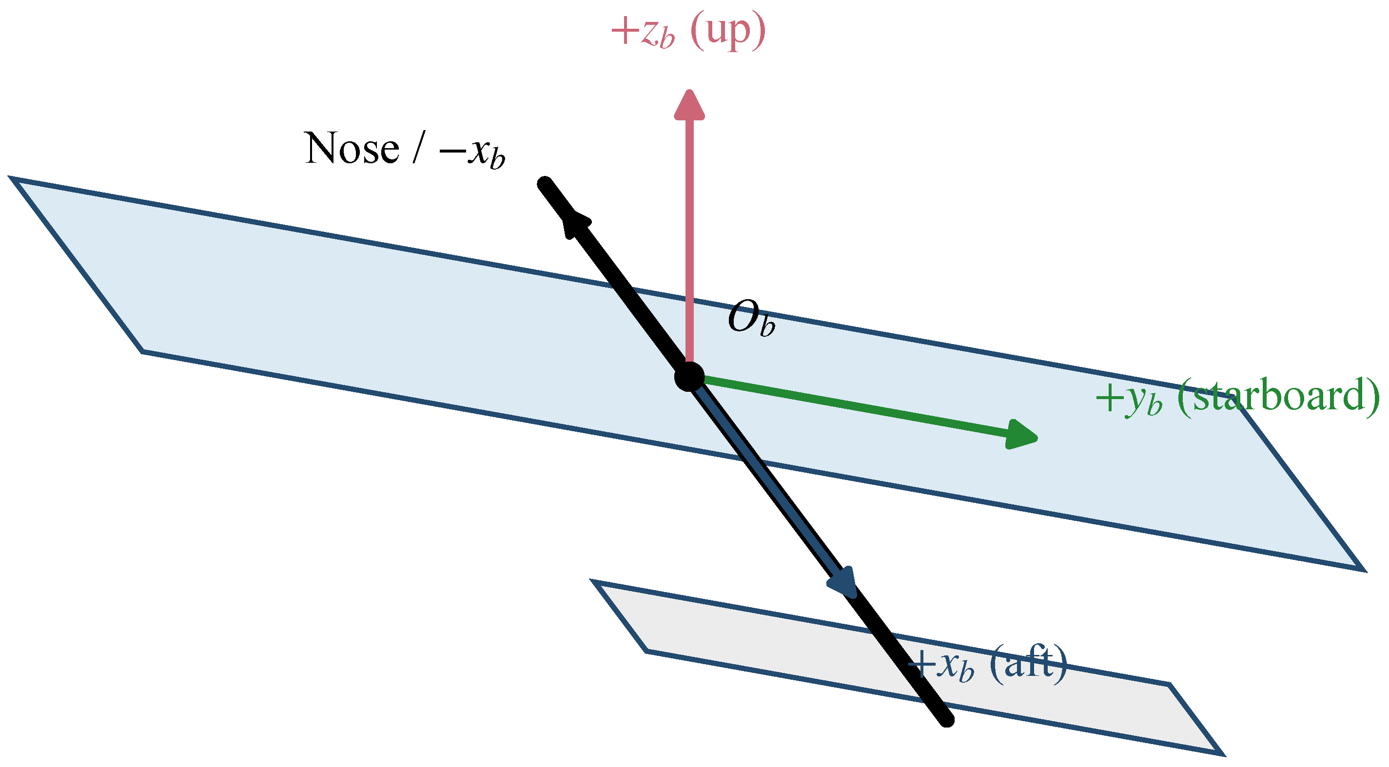
A right-handed body-axis system is used throughout (Figure 2). The positive axis points aft, the positive axis points toward the starboard wing, and the positive axis points upward; the nose direction is, therefore, . Connection DOFs 4, 5, and 6 are rotations about , , and , respectively. No local coordinate system is assigned to the connection cards, so their component numbers refer directly to these basic body axes.
The assembled structure is modeled as free–free. The analysis contains no support constraints, trim equations, gravitational load, or preceding static-load solution and, therefore, represents an unloaded linearization about the undeformed, zero-incidence geometry. The six global rigid-body modes are retained in the modal reduction to preserve the free–free basis. Following conventional low-order structural-flutter practice, post-processing excludes these non-oscillatory roots and reports the elastic and connection-related candidates beginning with the first elastic branch; no separate body-freedom-flutter model is introduced.
Figure 1.
Configuration and structural model illustrations of the wingtip-connected assembly. (a) Top-view arrangement of the three modules, planar CAERO1 lifting surfaces, and interface reference locations L and R; the middle UAV is the reference unit. (b) Three-dimensional illustration of one module, showing the main wing, fuselage representation, and horizontal tail. (c) Main-wing section illustration based on the NACA 0021 structural contour. In (b,c), blue-purple identifies ribs and tail surfaces, coral orange the longitudinal wing members, and gray the fuselage. Colors identify components, not response magnitudes. These structural illustrations complement the zero-thickness DLM surfaces in (a). The panels use different scales; interface constraints and rotational springs are detailed in Figure 3.
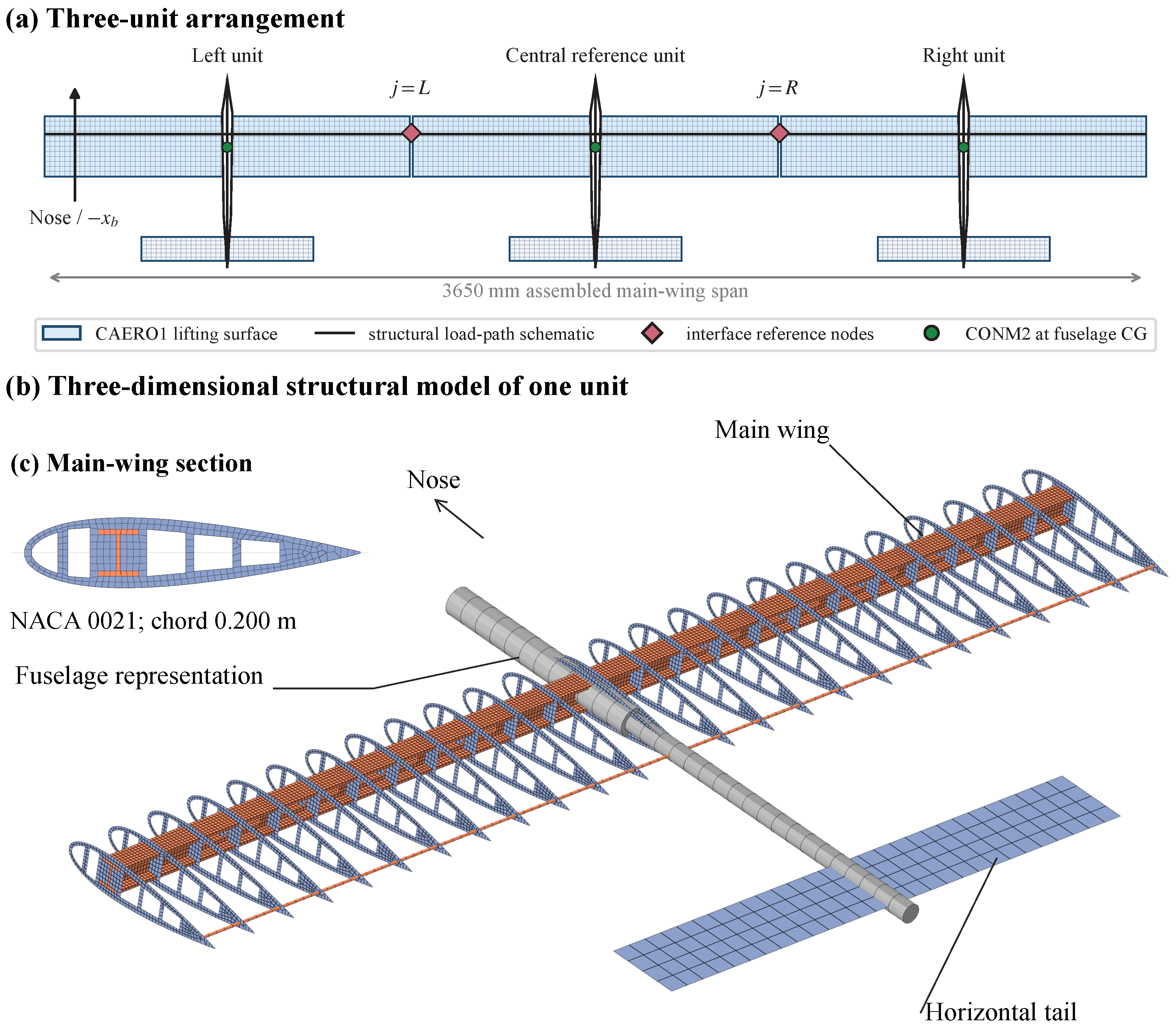
Figure 2.
Body-axis convention used by the structural and aerodynamic models. The nose points in the direction; DOFs 4–6 are rotations about , , and , respectively.
2.2. Structural and Aerodynamic Formulations
In physical coordinates, the linear structural model is given in Equation (1)
where is the physical-coordinate structural displacement vector containing nodal translations and rotations, and overdots denote time derivatives. The matrices and are the airframe mass and stiffness matrices, is the contribution of the finite interface springs, and is the unsteady aerodynamic load. Active shell elements represent ribs, reinforced wing-root/tip regions, and tail surfaces; solid elements represent the aluminum main-wing load path; beam elements represent the rear wing member and fore/aft fuselage members and three concentrated-mass elements carry the discrete fuselage/equipment mass and inertia. The structural damping matrix is set to zero. Aerodynamic damping remains included through the coupled aerodynamic forces. Joint damping, translational compliance, preload, friction, and free-play are outside the present model.
Subsonic unsteady aerodynamic loads are calculated with the doublet-lattice method (DLM) on CAERO1 lifting surfaces and transferred to the structural model through SPLINE1 interpolation [15]. The main wings and horizontal tails are represented by 12 planar, zero-thickness lifting surfaces in the same interference group. Their common aerodynamic influence-coefficient system includes mutual linear coupling among the modeled surfaces, including adjacent-wing and main-wing/tail coupling. The structural airfoil thickness shown in Figure 1c is not resolved in this aerodynamic model. The fuselages and the short connection regions have no CAERO1 panels and, therefore, receive no direct aerodynamic pressure. Their inertia and stiffness nevertheless enter the generalized structural dynamics, while direct body aerodynamic loads and wing–fuselage junction-flow effects are omitted. The linear lifting-surface approximation does not resolve viscous separation or nonlinear wake roll-up. The complex harmonic displacement amplitude is denoted by , so that . The harmonic aerodynamic load and its modal projection are given in Equation (2)
where the dynamic pressure, reduced frequency, and reference semichord are defined in Equation (3)
The reference data are given in Equation (4)
Mach number and density are deliberately held fixed while the velocity parameter is swept. The velocity sweep changes dynamic pressure and reduced frequency while the aerodynamic matrices retain . This defines a common comparison condition for the stiffness cases. At fixed sound speed a, a physical speed trajectory would instead obey ; the present parameter sweep is, therefore, a conditional numerical comparison rather than such a trajectory. The error associated with holding Mach number fixed has not been quantified. The consequences of the fixed flight-condition parameters and zero structural damping are revisited in the limitations discussion.
2.3. Interface Implementation and Stiffness Cases
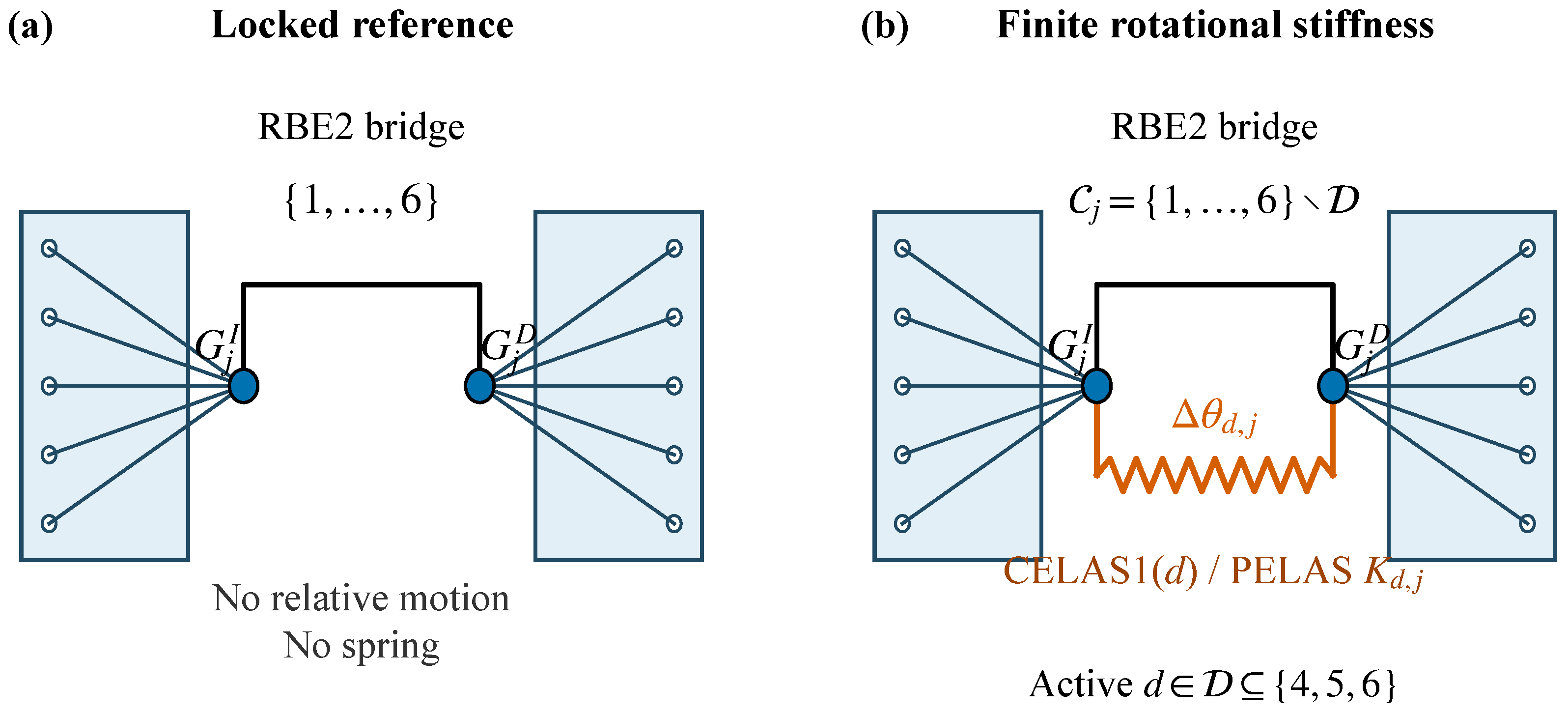
The two interface reference locations are mm and mm in the basic body axes. At each interface, the central-side and outboard reference nodes are linked by the bridge constraint, while the surrounding section nodes are collected to their respective reference nodes by RBE2 spiders (Figure 3).
Figure 3.
Interface constraint idealization. Sectional RBE2 spiders collect the central and outboard cross-sections to reference nodes and . (a) In the locked reference, the bridge RBE2 constrains components 1–6 and no spring is present. (b) For finite rotational stiffness, each active rotation is removed from the bridge component set and transferred by a CELAS1 element with PELAS stiffness ; translations and inactive rotations remain constrained.
For interface j, the relative rotation vector and an active component d are defined in Equation (5)
The exact locked baseline uses bridge components 123456. For a finite DOF 4, 5, or 6 stiffness, the bridge component set becomes 12356, 12346, or 12345, respectively, and the released component is connected by CELAS1 with a PELAS rotational stiffness. Thus, two CELAS1 elements are used per active rotational channel, one at each interface. For an active set , the spring energy and stiffness matrix are given in Equation (6)
All translations and every inactive rotation remain exactly constrained by the RBE2 bridge. Consequently, a single-channel case varies only the stated rotation; it does not release the other rotations.
This stiffness-only linear interface idealization is adopted to isolate rotational-channel effects. The reported crossings are conditional, model-specific sensitivity indicators for the monitored low-frequency response, not experimentally validated flutter boundaries or absolute stability limits of a manufactured joint. No experimental measurements or joint-damping calibration data are available for the present configuration.
The finite-stiffness normalization is defined in Equation (7)
For symmetric cases, and the 21-point grid is specified in Equation (8)
corresponding to –. The exact released limit uses and contains no spring in the selected channel; the exact locked limit retains the full RBE2 bridge. A separate large-stiffness proxy uses and is not identified with . Table 3 summarizes the resulting production matrix.
Table 3.
Connection-stiffness parameter families.
The simultaneous two- and three-channel families are one-dimensional equal-stiffness co-variation paths, not factorial interaction designs. For an unequal-interface case, the descriptive mean and normalized contrast are defined in Equation (9)
These coordinates describe the mean stiffness and signed left–right contrast of each prescribed pair. Their inverse is and . No additional functional relation between and was imposed, and they were not sampled independently. The results are consequently compared case by case. The symmetric reference satisfies and .
2.4. Structural Modes, Target Response, and p–k Settings
For every stiffness configuration, the structural basis is recomputed from Equation (10)
For a structural mode with generalized mass , the fraction of its strain energy stored in the active rotational springs is evaluated using Equation (11)
This quantity is used only as a complementary dry-structural diagnostic; it is neither independent validation nor an identification of a complex aeroelastic root.
The locked-reference dry-modal solution contains six numerically near-zero rigid-body roots. Its first four elastic frequencies, corresponding to branches 7–10, are 3.764998, 5.230965, 6.056869, and 10.46946 Hz. These dry structural frequencies must not be equated with p–k crossing frequencies: aerodynamic coupling shifts the locked low-frequency target response to approximately 2.394 Hz at its zero-damping crossing.
Complete release of one rotational channel at both interfaces adds two near-zero internal mechanisms to the six-dimensional global rigid-body subspace. Individual near-zero eigensolutions can mix these motions. The original oscillatory reporting filter excludes near-zero-frequency roots; the additional released-DOF 5 assessment in Section 4.2 examines the real parts of the eigenvalues separately, retaining the complete structural basis. When finite stiffness is restored, the joint-sensitive descendants move to finite frequency and are included in the stiffness study. The primary aeroelastic scope is the low-frequency connection response that approaches the locked branch-7 result near 2.394 Hz. Higher-frequency candidates are retained in the secondary audit rather than used to formulate the principal low-frequency trends.
For every stiffness configuration, the eigensolver is requested to return the lowest 36 structural eigensolutions from a 0 Hz lower bound, including the six free–free rigid-body modes; no upper-frequency cutoff is imposed. All 36 are supplied to the p–k aeroelastic analysis. The p–k implementation uses linear interpolation, 36 requested roots, and an iteration threshold of . The fixed 35-point velocity list is given in Equation (12)
The reduced-frequency list is given in Equation (13)
2.5. Crossing Extraction and Target-Mechanism Selection
The post-processor groups output rows by solution-branch index P and tests adjacent velocity samples using Equation (16)
The index condition organizes the locked-reference rigid-body entries, while the frequency condition excludes near-zero roots from oscillatory-crossing reporting. For released interfaces, mixed near-zero eigensolutions require the separate mechanism assessment rather than identification by output index alone. The index is used for organizing the sampled output and is not assumed to retain identical physical content at every stiffness. For an accepted bracket, linear interpolation gives Equation (17)
The enclosing sampled interval, rather than the printed interpolation digits, defines the velocity resolution.
Contacts for which both bracketing values satisfy are classified as neutral-band diagnostics rather than sign-changing candidates. This fixed threshold is a post-processing guard set above the observed –-level plateaus in the exported damping histories; it is distinct from the p–k iteration threshold and is not an uncertainty estimate. A retained crossing must lie outside the neutral band on both sides of the sign change and remain positive at the next two available velocity samples.
For each ordered symmetric family, dynamic programming is first used only to organize the scalar candidate set and propose an initial path. For a candidate , the screening target and transition costs are given in Equations (18) and (19)
The 2.4-Hz term directs this initial screen toward the response of interest, but neither this cost nor continuity of P establishes physical modal identity. The screen proposes a locked-reference-oriented candidate path, which is subsequently audited between adjacent stiffness cases using complex aeroelastic eigenvectors. MAC is, therefore, used as a modal-identity validation criterion rather than as an independent exhaustive global branch-search algorithm. A failed audit triggers local reassociation and revalidation; frequency and solver index alone never determine the replacement.
Comparable eigenvectors are exported on a fixed set of 774 structural GRID points obtained from the union of the existing aerodynamic interpolation regions. Only complex translations are used, and every compared case uses the same ordered coordinate set and the same unweighted complex inner product. The mass normalization in Equation (10) fixes the dry structural basis but does not introduce an additional physical-coordinate mass metric for the reconstructed p–k vectors. If denotes the corresponding raw vector and is an orthonormal six-column rigid-motion basis constructed in the same coordinates, the deformation vector is given in Equation (20)
For two roots a and b, the complex modal assurance criterion is defined in Equation (21)
Raw and deformation MAC matrices are evaluated separately, and their arithmetic mean is retained as a combined diagnostic. The combined value is not allowed to rescue a failure of either constituent MAC. Automatic association considers every root with finite damping and positive frequency; no relative-frequency window or prescribed solver index is used. The selected raw, deformation, and combined entries must all be mutual row–column maxima, and each selected value must exceed its strongest row and column competitor by at least 0.10. A segment is classified as strong-unique when all three MAC values are at least 0.90, conditional when they are at least 0.80, and failed otherwise. Conditional or conflicting stiffness intervals are checked through an additional model at the geometric stiffness midpoint. A modal association is accepted only when forward and reverse selections converge through the same midpoint root.
Within each stiffness case, the proposed root is also audited across velocity through adjacent complex-MAC comparisons. The target crossing is the negative-to-nonnegative damping transition on the validated velocity trace; post-crossing persistence is assessed along that trace rather than by holding solver index P fixed. This distinction is required when root ordering changes inside a case. Solver POINT, frequency, and crossing speed are consequently reported properties of the validated candidate path, not identity criteria.
Two outputs are distinguished in Equation (22)
where is the locked-reference-oriented, MAC-validated candidate path and contains the persistence-supported scalar candidates together with any target contact recovered during velocity-wise MAC validation. supplies the principal result; is a secondary audit that can include a different mechanism and is not used to redefine the target. Their difference indicates candidate competition, not a switch of the monitored path. Unequal-interface and limiting cases have no continuous stiffness path; their target-nearest values are, therefore, selected independently and are not represented as a cross-case physical branch.
The reported metrics are used as target-specific stiffness-sensitivity measures. A crossing speed and crossing frequency may be reported for every supported oscillatory mechanism; the terms case-wise minimum or global onset are reserved for the lowest supported contact and are not used as synonyms for the monitored target. After the initial screen, 62 configurations whose selected target or secondary candidate was enclosed by a velocity interval wider than 0.5 m/s were rerun with 0.25 m/s local increments inside the original bracket. All structural, aerodynamic, modal, reduced-frequency, and flight settings were unchanged. Three unequal-DOF 5 cases that were already unstable at the original 5 m/s lower bound were additionally sampled from 0.5 to 5 m/s in 0.25 m/s increments. Separate sparse-output diagnostics then supplied the complex vectors used for MAC association without changing the production models. At the low-stiffness end of the three-channel path, full-speed Case01/Case02 diagnostics and geometric stiffness midpoints closed the reverse trace from Case03. The final reported target and secondary candidates are, therefore, enclosed by intervals no wider than 0.5 m/s.
A post-processing robustness audit was performed without changing any production solution. The ordered scalar screen was repeated in the reverse stiffness direction, with each of its five weights varied individually by , and with the locked-frequency and solver-index target terms removed together. The final MAC ledger was also reevaluated for minimum MAC gates of 0.80–0.95 and competitor margins of 0.05–0.15, and the neutral-band classification was repeated for –. These tests assess the reporting logic rather than add new physical-model parameters; the resulting sensitivity summaries are reported in Section 4.1.
A candidate already persistently unstable at the sampled lower bound is reported as left-censored rather than assigned an interpolated onset below the sampled range. The three extended unequal-DOF 5 cases remain left-censored at 0.5 m/s.
2.6. Numerical Evidence and Scope
The calculations provide internally controlled comparisons because the same structural idealization, aerodynamic discretization, damping assumption, atmospheric parameters, modal setting, velocity list, and reduced-frequency list are used throughout the 179-case matrix. The structural modes are recomputed after every stiffness change. The checks in Table 4 assess the settings used for the monitored low-frequency response; they concern numerical settings and modal identity within this model. The additional independent aeroelastic-solver comparison is reported in Section 3.7.
Table 4.
Numerical evidence supporting the declared low-frequency analysis scope.
3. Numerical-Setting Adequacy and Locked Reference Response
This section establishes numerical-setting adequacy for the monitored low-frequency response of the exact locked configuration. The comparisons cover modal truncation, local velocity and reduced-frequency sampling, selected aerodynamic meshes, and a five-configuration cross-solver check. Their scopes are stated separately.
3.1. Assessment Scope and Locked Configuration
The reference assembly comprises three identical UAV modules in a free–free structural condition, with both wingtip interfaces locked by six-component rigid bridges. The bridge topology differs from the finite stiffness normalization used in the parameter paths. Across the checks, the structural and aerodynamic definitions, flow assumptions, and spline coupling are unchanged; only the numerical quantity stated in Table 5 is varied.
Table 5.
Assessment matrix for the 14 archived runs (12 unique numerical settings).
Table 6 collects the adopted reference settings. The scalar candidate-screening heuristic used to initialize the ordered-path audit is not used to make the setting decisions in this section. Instead, the locked branch-7 crossing is monitored directly because it defines the reference response for the subsequent candidate-path validation. Branch numbers are output indices used to organize the sampled histories and are not treated as physical identities.
Table 6.
Baseline model and validation settings used in the numerical checks.
3.2. Treatment of Rigid-Body and Released-Interface Roots
The exact locked free–free structural solution contains the expected six global rigid-body modes, followed by its first elastic mode. These six motions are retained in the modal reduction and excluded from the reported elastic candidate set. A complete rotational release at both interfaces introduces two additional near-zero interface-mechanism roots, one for each released connection, without replacing the six global rigid-body modes. The original oscillatory-crossing filters exclude near-zero roots from that reporting set; the additional analysis in Section 4.2 examines their non-oscillatory behavior separately. When finite connection stiffness is assigned, the corresponding relative rotations acquire nonzero frequencies and enter the low-frequency response studied here.
3.3. Modal-Basis Assessment
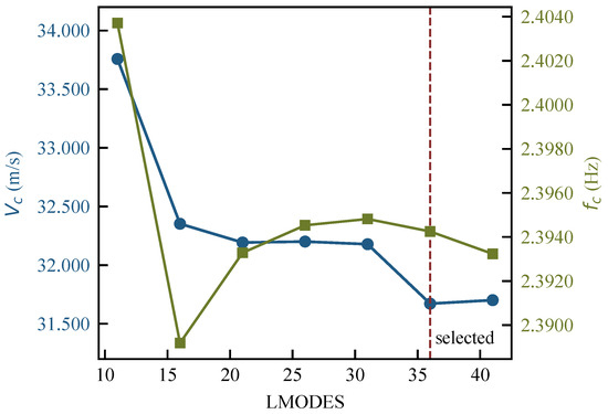
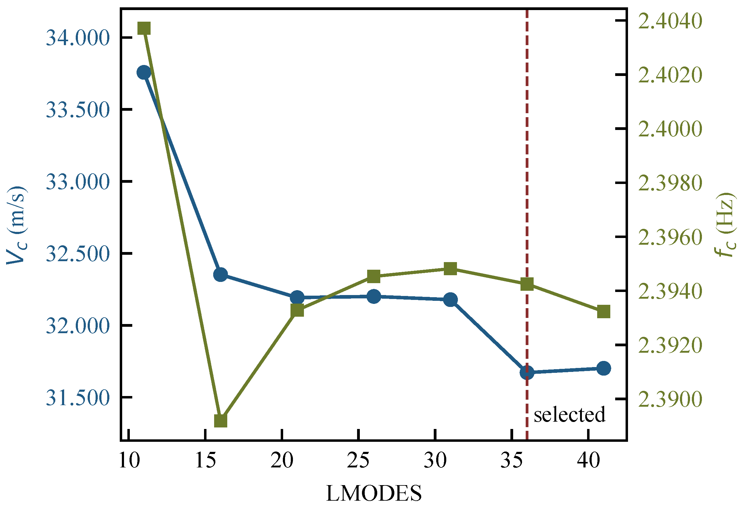
The locked-reference basis was increased from 11 to 41 requested eigensolutions while all other settings were held fixed. Table 7 and Figure 4 show that the monitored crossing approaches a stable value as additional elastic content is retained.
Table 7.
Modal-truncation sensitivity of the monitored POINT 7 crossing.
Figure 4.
Sensitivity of the locked low-frequency branch-7 crossing to the number of requested structural eigensolutions. LMODES = 36 is adopted for the stiffness matrix.
Relative to LMODES = 41, LMODES = 26 differs by 1.575% in speed and 0.054% in frequency, so it also satisfies the 2% and 1% limits. These limits do not define a first-passing stopping rule. The subsequent increase from 31 to 36 modes changes speed by approximately 1.6%, whereas increasing from 36 to 41 changes speed by 0.094% and frequency by approximately 0.043%. LMODES = 36 is retained as a uniform setting supported by this next-increment stabilization, rather than as the minimum mode count meeting the limits. This evidence concerns the monitored locked-reference response. Percentages are evaluated from unrounded frequencies and speeds; the frequency change is quoted approximately as 0.043%.
3.4. Velocity and Reduced-Frequency Sampling
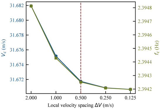
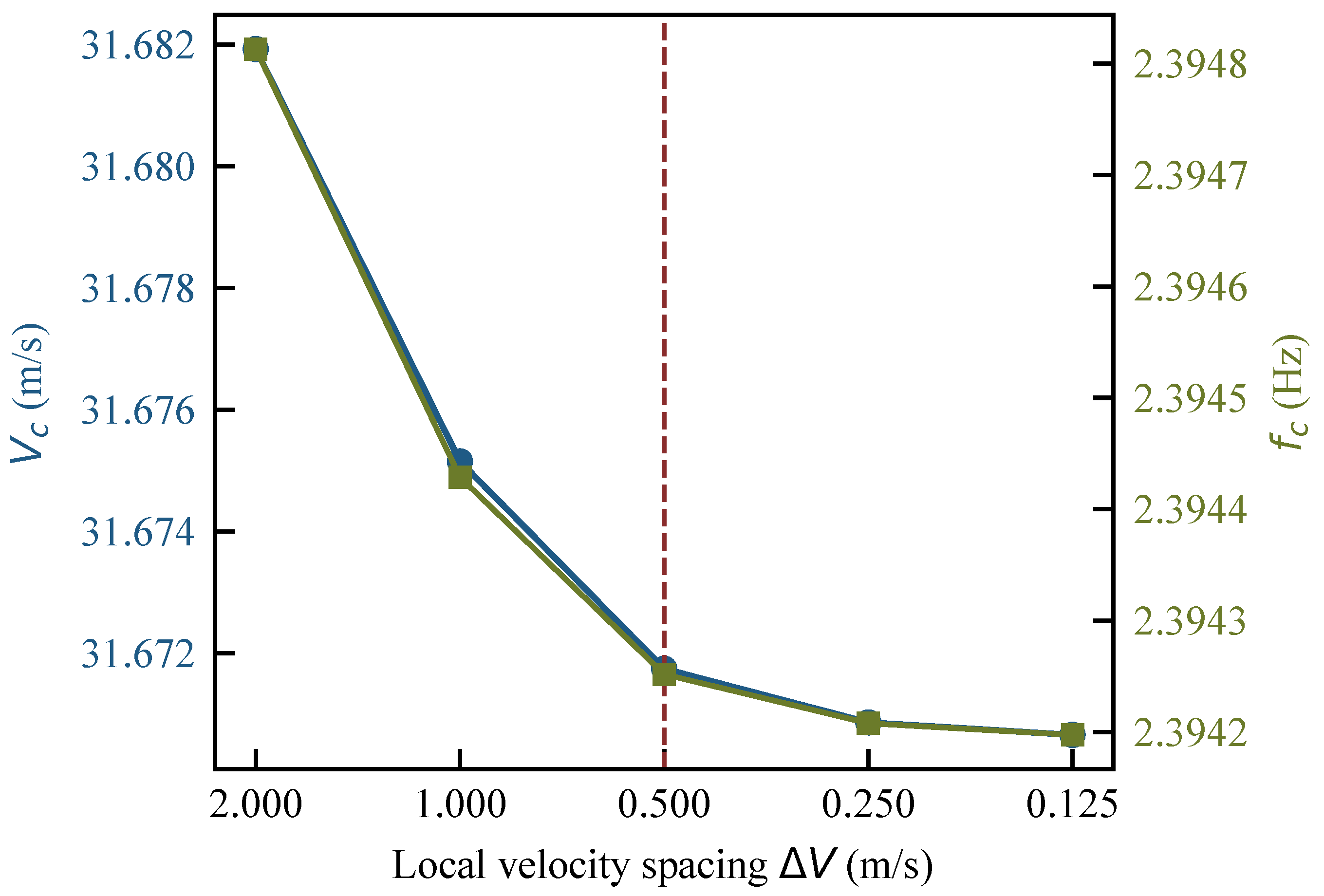
Local velocity spacing around the locked crossing was successively reduced from 2 to 0.125 m/s (Table 8 and Figure 5). Between V050 and V025, the interpolated speed changes by 0.000882 m/s and the frequency by 0.00184%, below the adopted 0.2 m/s and 0.5% limits. V050 is consequently adequate in this locally refined interval. This result is not transferred to off-reference candidates sampled with wider intervals; those results are reported together with their brackets.
Table 8.
Local velocity-resolution sensitivity of the monitored POINT 7 crossing.
Figure 5.
Local velocity-sampling sensitivity of the locked low-frequency branch-7 crossing. The production velocity table uses 0.5 m/s spacing in the neighborhood of this response.
The standard 32-value reduced-frequency list was also compared with a 43-value list containing 11 additional intermediate values (Table 9). The branch-7 results differ by m/s and Hz at the stored precision, supporting use of for the monitored response.
Table 9.
Reduced-frequency-list sensitivity of the monitored POINT 7 crossing.
3.5. Adopted Setting and Reference Crossing
The adopted LMODES = 36, V050, and settings give Equation (23)
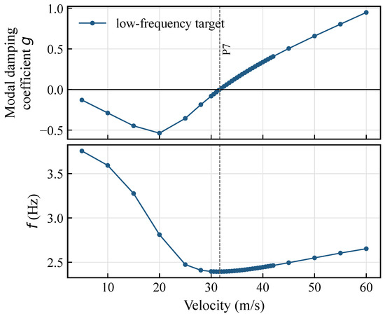
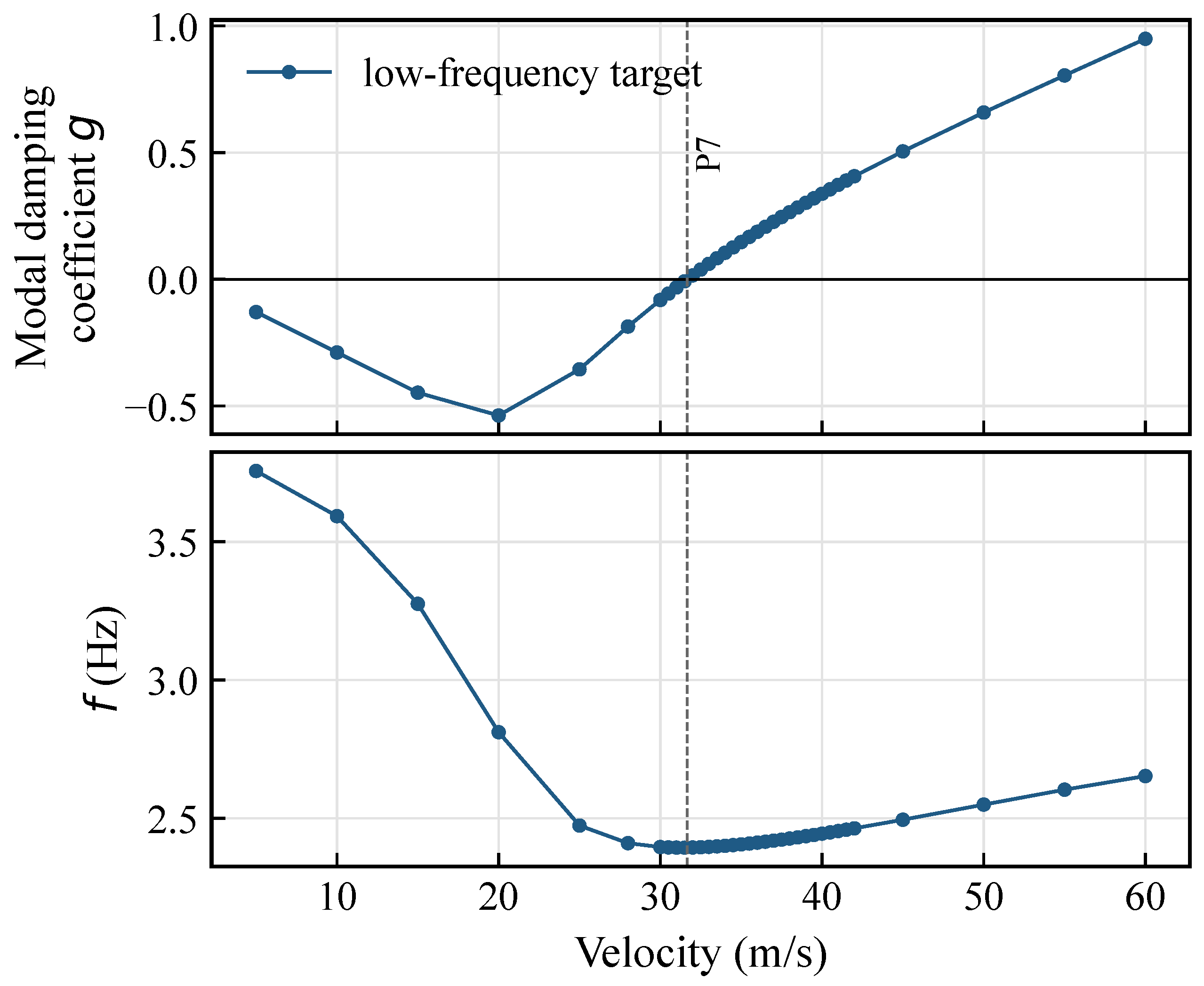
with the zero-damping change sampled between 31.5 and 32.0 m/s. Equation (23) is the interpolated scalar reference within that bracket, not a claim of sub-bracket physical accuracy. Table 10 lists the adopted settings, and Figure 6 shows the corresponding damping and frequency histories.
Table 10.
Selected numerical settings and locked-reference candidate responses.
Figure 6.
Locked-reference damping and frequency histories for the approximately 2.4-Hz target mechanism under the adopted settings. The dashed line marks its interpolated zero-damping crossing.
Accordingly, the numerical evidence supports the adopted settings for the monitored low-frequency scalar response and for controlled comparison along the prescribed stiffness paths. Dry-modal results are used below as complementary structural diagnostics.
3.6. Aerodynamic-Mesh Sensitivity
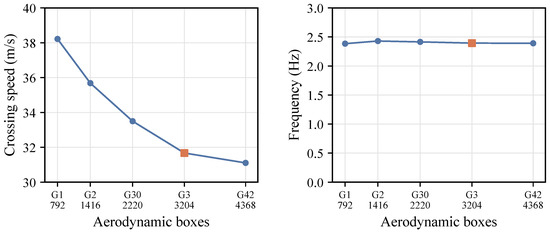
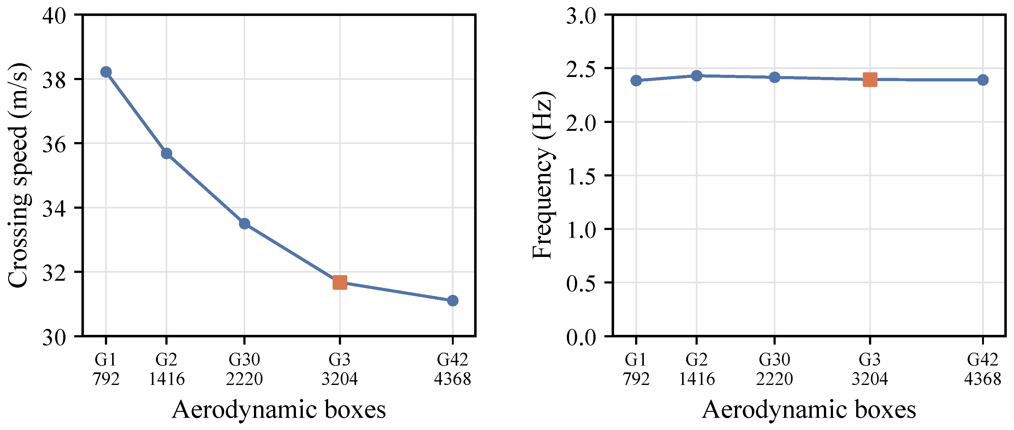
Table 11 compares five selected aerodynamic discretizations for the monitored locked-reference response. Figure 7 illustrates the corresponding speed and frequency trends. Production mesh G3 uses 3204 boxes; G42 uses 4368 boxes. The corresponding speeds are 31.6717 and 31.1047 m/s, with frequencies of 2.3943 and 2.3909 Hz. Relative to G42 and calculated before rounding, the differences are 1.823% and 0.140%, respectively. The coarser values are included to show the sensitivity across the selected levels. These differences measure one refinement beyond production G3, rather than error relative to a fully converged solution. G3 remains the common baseline; convergence for other stiffness cases or competing branches is not inferred from this selected comparison.
Table 11.
Selected aerodynamic meshes. Absolute relative differences use G42 as the denominator and are computed before rounding.
Figure 7.
Selected aerodynamic-mesh sensitivity of the monitored locked-reference crossing. Squares identify production mesh G3. The frequency axis spans 0–3 Hz; numerical differences are reported in Table 11.
3.7. Cross-Solver Comparison
Five configurations were compared using Nastran DLM/p–k and ZAERO ZONA6/g-method calculations: the exact lock, DOF5/01 and DOF5/11 at and 1, DOF4/14 at , and DOF6/01 at . Both use density 1.225 kg/m3, Mach 0.1, the free–free structure, 12 lifting surfaces with 3204 boxes, 36 structural modes, zero structural damping, and a 5–60 m/s sweep at 0.25 m/s increments. The modal inputs derive from the same structural models, so this check compares aeroelastic implementations rather than independently validating the structure. The matched-condition values in Table 12 supplement the production results under their original settings; they do not replace them.
Table 12.
Matched-condition low-frequency candidates from Nastran (N) and ZAERO (Z). Signed differences are .
ZAERO gives low-frequency speeds 10.225–10.269% above Nastran, while the frequency differences range from to %. Both reproduce the marked DOF5 target reduction and the weak changes of the selected DOF4/DOF6 targets. For DOF4/14, a separate lower-speed, higher-frequency candidate is also recovered: 22.5001 m/s and 7.1039 Hz in Nastran versus 23.0631 m/s and 7.1199 Hz in ZAERO (2.5021% and 0.2247% differences). This candidate is distinguished from the low-frequency comparison.
Complex-shape comparisons against the historical target support the four finite-stiffness associations; exact-lock historical complex-mode evidence is unavailable. The DOF4/14 higher-frequency candidate has raw and deformation MAC values above 0.9998 against its historical counterpart. These checks support the selected associations, but leave the approximately 10.2% low-frequency speed discrepancy unexplained. Modal import and near-zero-mode treatment differ numerically, and low-speed high-mode reduced-frequency extrapolation and near-zero-root warnings remain. The comparison, therefore, supports selected relative trends within the stated models, with an unresolved discrepancy in absolute speeds.
4. Results and Discussion
This section evaluates the effect of connection rotational stiffness on the screened p–k zero-damping response of the three-unit assembly. As summarized in Table 13, all 179 production configurations use the adopted 36-eigensolution setting, velocity table, reduced-frequency list, aerodynamic representation, and flight assumptions. The structural eigensolution is recomputed for every stiffness configuration; the common quantity is, therefore, the truncation setting, not one unchanged modal basis.
Table 13.
Original numerical-assessment and production matrix. Additional mesh, cross-solver and released-root checks are reported separately.
The principal result is the locked-reference-oriented candidate path that passes adjacent complex-eigenvector MAC validation across each ordered stiffness sequence. Dynamic programming supplies only an initial scalar-screening hypothesis; the MAC audit corrects a local proposal when solver ordering changes, and the final target never follows solver index or nearest frequency alone. The lowest-speed reporting-admitted candidate in each case is retained as a secondary audit quantity; in several DOF 4-containing paths it belongs to a distinct higher-frequency response and is shown separately from the validated target.
4.1. Candidate Evidence and Reporting Precision
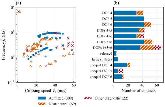
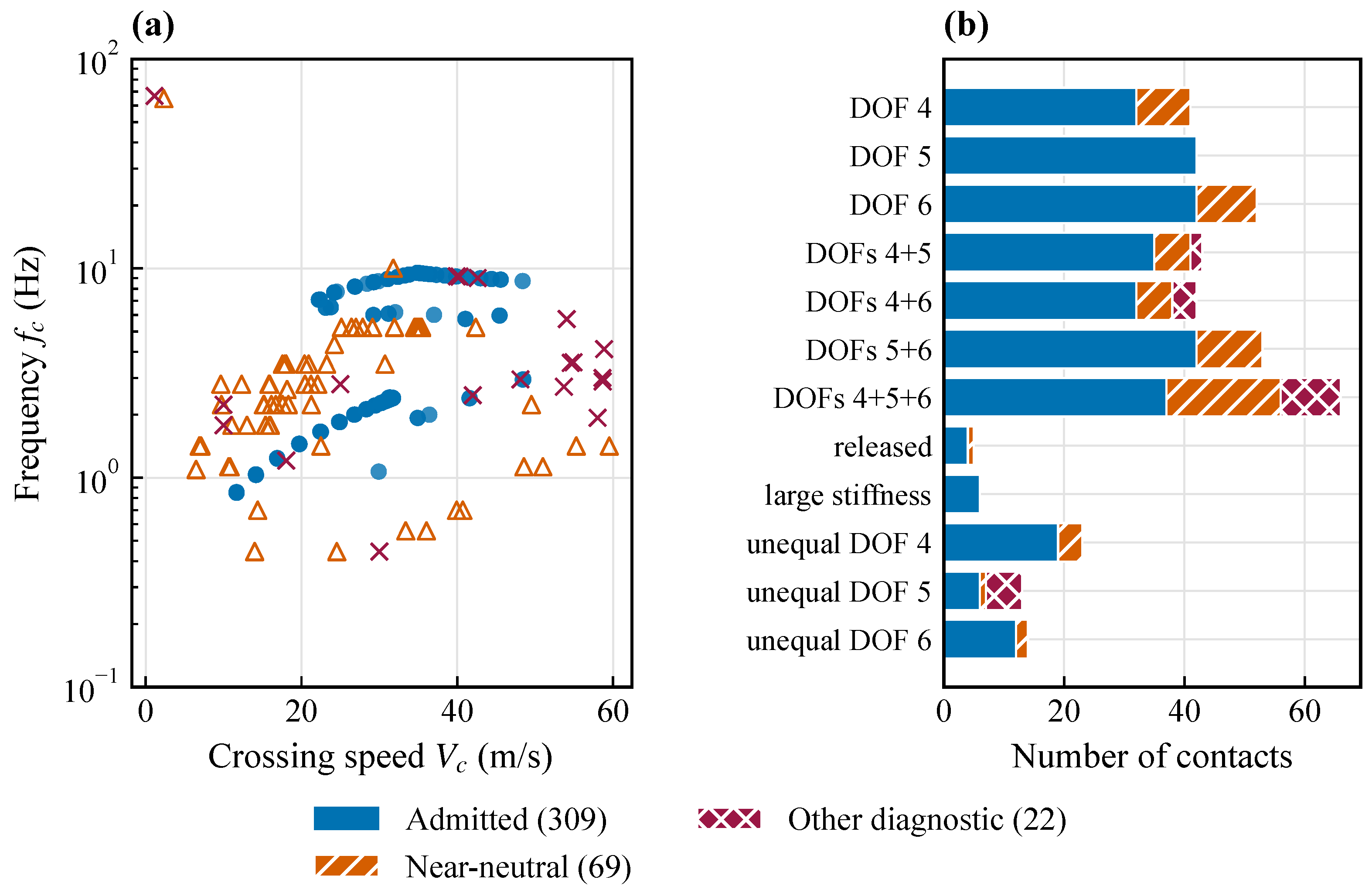
The production matrix contains 147 configurations on seven ordered symmetric or equal-stiffness paths, six locked/released/large-stiffness reference configurations, and 26 unequal-interface configurations. Each p–k calculation has a stiffness-matched dry-modal calculation used for complementary structural interpretation. After local velocity refinement, 400 negative-to-nonnegative scalar contacts are extracted. Of these, 69 lie in the neutral band; 17 of the remaining contacts fail or cannot complete the fixed-POINT two-following-sample persistence test, and six supported contacts belong to three configurations already persistently unstable at the sampled lower bound. This produces 308 scalar selection-admitted candidates. The velocity-wise MAC trace recovers one additional target contact in three-channel Case02 after the solver POINT reorders, giving 309 final reporting-admitted contacts and case-level assignments for 176 configurations; the remaining three are left-censored at 0.5 m/s. Figure 8 summarizes this screening inventory.
Figure 8.
Inventory of 400 scalar contacts after local velocity refinement: (a) crossing speed and logarithmic frequency: blue circles, reporting-admitted; orange open triangles, near-neutral diagnostics; magenta crosses, other diagnostics. (b) Classified counts by family. The reporting pool includes scalar selection-admitted contacts plus one target recovered by velocity-wise MAC after solver-POINT reordering; remaining contacts are diagnostic only.
Table 14 reports the target sequence and the secondary minimum for each ordered path. A reported crossing comprises its sampled velocity bracket and the linearly interpolated value. All final selected brackets are no wider than 0.5 m/s; the printed interpolation digits are retained for traceability. The two quantities differ in 28 of the 147 ordered cases and in three further unequal-interface DOF 4 cases. This is evidence of multiple reporting-admitted contacts, not a count of physical mode switches.
Table 14.
Low-frequency target sequences and lowest-speed secondary candidates for the seven ordered stiffness paths (21 cases per path). Each entry gives the range of in m/s followed by the paired range in Hz. is the largest sampled velocity-bracket width for the final target/secondary selections.
Reversing the stiffness order gives the same scalar optimum in all 147 ordered cases. Varying any one cost weight by changes at most two low-stiffness proposals, whereas removing the locked-reference target terms changes 64 proposals. The target terms specify the response family. Modal identity is consequently based on the independent complex-MAC audit: all 140 ordered edges remain accepted for minimum MAC gates from 0.80 to 0.90 and competitor margins from 0.05 to 0.15. Increasing the MAC threshold to 0.95 retains 135 of the 140 associations; the remaining five have deformation MAC values of 0.9153–0.9410 and satisfy the adopted 0.90 criterion. Changing from to changes the number of neutral diagnostic contacts from 67 to 72 but reclassifies none of the final targets.
4.2. Locked, Large-Stiffness, and Released Limits
The exact RBE2-locked reference is given in Equation (24)
For each rotational channel, a large-stiffness proxy with reproduces this monitored scalar response to the stored precision. This agreement supports the use of the finite proxy as a limiting comparison, although its spring topology is not mathematically identical to the exact six-component RBE2 lock.
The bilateral released limits are channel-specific. Releasing DOF 4 gives 31.279 m/s at 2.399 Hz, and releasing DOF 6 gives 31.672 m/s at 2.394 Hz. For released DOF 5, the production contact at approximately 48.395 m/s and 8.712 Hz is a different retained candidate, not the limiting low-frequency target. The additional PK calculation covers 0.5–120 m/s. PKS checks at 11 velocities (0.5, 1, 2, 5, 10, 20, 40, 49.5, 49.75, 60 and 120 m/s) search 0–2 Hz with all 36 structural modes retained. Increasing the search resolution from 1000 to 2000 intervals changes matched eigenvalues by at most s−1.
These checks recover non-oscillatory growing roots with joint-mechanism participation. No positive-real-part oscillatory root is found in the sampled PKS window. A local transition from a decaying complex pair to two negative real roots is also resolved. After removing the global rigid-body component for diagnostic purposes, the low-order relative motion approaches the two-interface mechanism subspace as finite stiffness decreases; this projection does not remove modes from the solver basis. The results distinguish a change in low-frequency response type from an unrelated higher-frequency crossing. They establish neither a unique continuation of the original target nor an onset below 0.5 m/s. Near-zero-root warnings and high-mode reduced-frequency extrapolation limit the scope of this diagnostic assessment.
4.3. Symmetric Single-Channel Paths
The low-frequency target is defined by the locked-reference-oriented branch and its complex-MAC associations along each ordered stiffness path. It is not independently reselected as the lowest-frequency or lowest-speed candidate in each case. The case-wise minimum is reported alongside this target to expose competition.
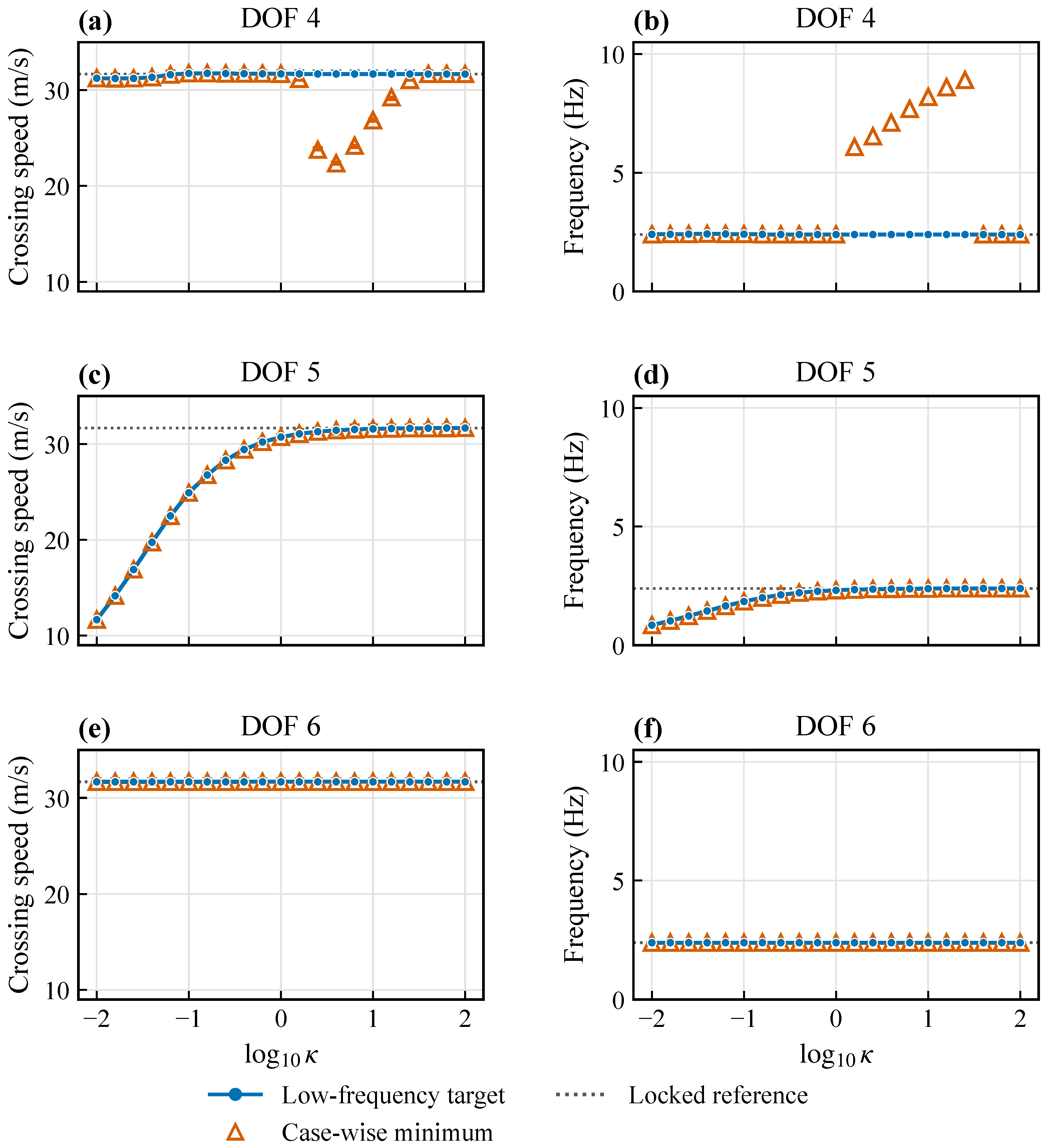
Figure 9 compares the three symmetric single-channel paths. Lines connect only the selected low-frequency target sequence along the common stiffness grid. Open triangles show the case-wise minimum candidate without connecting it across cases, because it may arise from different branches and frequency regions. Where the minimum coincides with the target, the two symbols are nested at their common coordinates. The absence of a separate secondary marker, therefore, does not imply that every higher-speed contact has ceased to exist.
Figure 9.
Screened results along the symmetric single-channel paths. Rows correspond to DOF 4, DOF 5, and DOF 6; panels (a,c,e) show crossing speed and sampled velocity bracket, and panels (b,d,f) show the corresponding frequency. Connected blue circles denote the low-frequency target sequence; open orange triangles denote the case-wise minimum in the reporting-admitted set. Coincident selections are displayed as a blue circle within an open triangle. Separate triangles identify secondary candidates and do not imply continuation of one higher-frequency mode across cases. The locked value is a numerical reference.
Within the adopted normalization, sampled stiffness range, and prescribed single-channel paths, the DOF 5 path shows the largest migration of the tracked low-frequency target among DOFs 4–6. Along this path, increases from 11.669 to 31.662 m/s while increases from 0.848 to 2.393 Hz; the target and secondary minimum coincide in all 21 cases. The lowest value is enclosed by the 11.50–11.75 m/s local bracket. By comparison, the DOF 6 target changes least within the adopted resolution: the two metrics remain between 31.671 and 31.672 m/s at approximately 2.394 Hz.
The DOF 4 target sequence is likewise confined to 31.211–31.750 m/s and 2.394–2.420 Hz. In 7 of 21 cases, however, a different supported contact occurs at a lower speed, reaching 22.368 m/s in a separate frequency region. It is not taken as a continuation of the low-frequency connection mechanism. Thus, among the prescribed single-channel paths, the DOF 4 path shows the clearest lower-speed candidate competition, while the DOF 5 path exhibits the largest migration of the tracked low-frequency target.
Within the present model, these lower-speed DOF 4 contacts occupy a localized intermediate-stiffness pocket rather than changing the small variation of the monitored low-frequency target. Including the neighboring persistence-supported contacts that lie above the target, the higher-frequency candidate locus is approximately 45 m/s in the 45–50 m/s sampled bracket at , decreases to 22.368 m/s at , and then rises to 33.828 m/s at ; its paired frequency increases smoothly from 5.959 to 9.362 Hz. Across Cases 11–21, adjacent diagnostic deformation-MAC values of 0.947–1.000 support, but do not by themselves establish, a continuous higher-frequency response. In Cases 12–18, this contact lies below the monitored target and is, therefore, the lowest reporting-admitted contact in the retained candidate set. It is retained as a diagnostic observation but is not used to define the monitored low-frequency trend or an independent stiffness law.
The stiffness-matched dry-mode track nearest this candidate locus has a DOF 4 spring-energy fraction of 0.075 at , a maximum of 0.346 at , and 0.039 at . The participation maximum occurs at the same sampled stiffness as the candidate-speed minimum, providing a model-specific structural correlate for the local pocket. This correlation does not establish the cause of the speed reversal or support a general DOF 4 trend; generalized aerodynamic-work and complex-phase diagnostics, together with high-frequency-specific discretization checks, would be required for such an interpretation. The localized candidate pocket, therefore, does not alter the finding that the monitored low-frequency target exhibits only limited migration along the prescribed DOF 4 path.
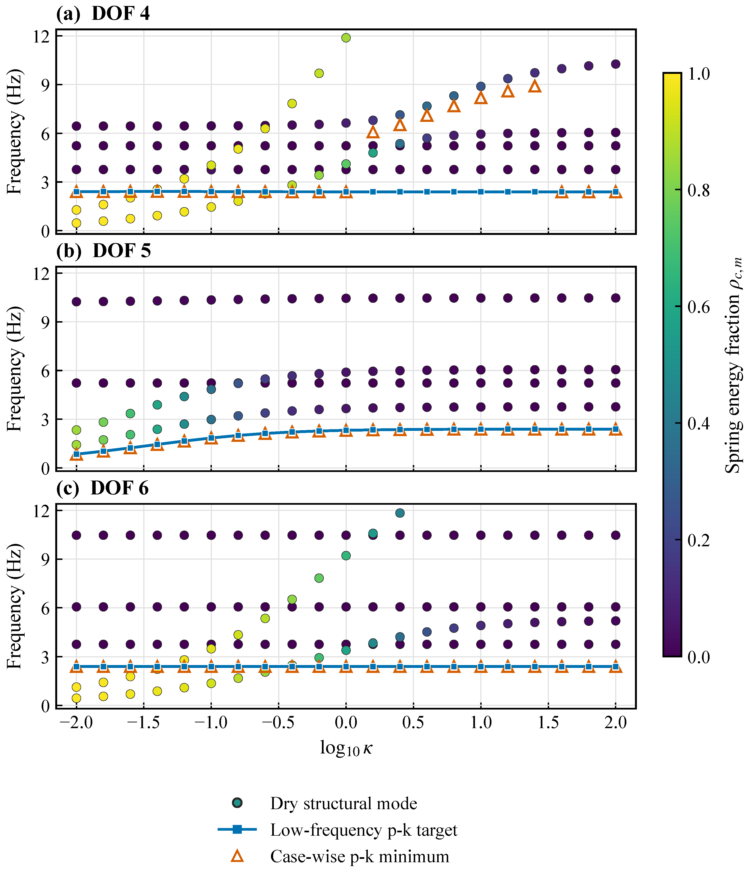
The stiffness-matched dry-modal results provide a complementary structural diagnostic for this directional contrast. Figure 10 shows dry elastic frequencies below 12 Hz colored by the interface-spring modal-energy fraction . The p–k candidate frequencies are overlaid to compare trends across the prescribed stiffness cases.
Figure 10.
Complementary dry-structural diagnostics for (a) DOF 4, (b) DOF 5, and (c) DOF 6, arranged vertically with common axes. Colored circles show the dry-mode frequencies up to 12 Hz and their interface-spring modal-energy fraction . Blue squares joined by a line show the low-frequency p–k target; open orange triangles show the case-wise minimum candidate. Nested squares and triangles indicate coincident selections. All previously displayed dry-mode points are retained; the dry modes provide structural diagnostics rather than independent validation of the aeroelastic crossings.
At , the two lowest interface-spring-dominated dry modes () occur at 0.467 and 1.278 Hz for DOF 4, 1.426 and 2.335 Hz for DOF 5, and 0.444 and 1.128 Hz for DOF 6. Within dry modes 7–18, such participation persists to approximately for DOF 4, 0.04 for DOF 5, and 1.6 for DOF 6. The channels, therefore, reorganize dry frequency and connection participation over different stiffness intervals. This supports the structural plausibility of channel-dependent sensitivity, but it neither validates the aeroelastic prediction independently nor explains its ordering: DOF 6, for example, retains low-frequency connection-participating dry modes while its target aeroelastic sequence changes little.
The directional contrast is nevertheless consistent with the kinematics of the interface. DOF 5 is rotation about the spanwise axis and is, therefore, kinematically associated with changes in the relative section-pitch/twist compatibility between adjacent wing modules. Varying this stiffness can alter the torsional content and its frequency proximity to the bending component of the monitored low-frequency response; the associated change in relative modal amplitude and phase then modifies the generalized aerodynamic damping and the zero-damping speed. DOF 6 is a yaw-like rotation about and is less directly associated with lifting-surface incidence changes, consistent with its much smaller target migration. This is a physically motivated bend–torsion coupling interpretation supported by the axis definition and dry-modal trends, rather than a quantitative causal decomposition; confirmation would require complex-shape phase or generalized aerodynamic-work diagnostics.
4.4. Equal-Stiffness Multi-Channel Paths
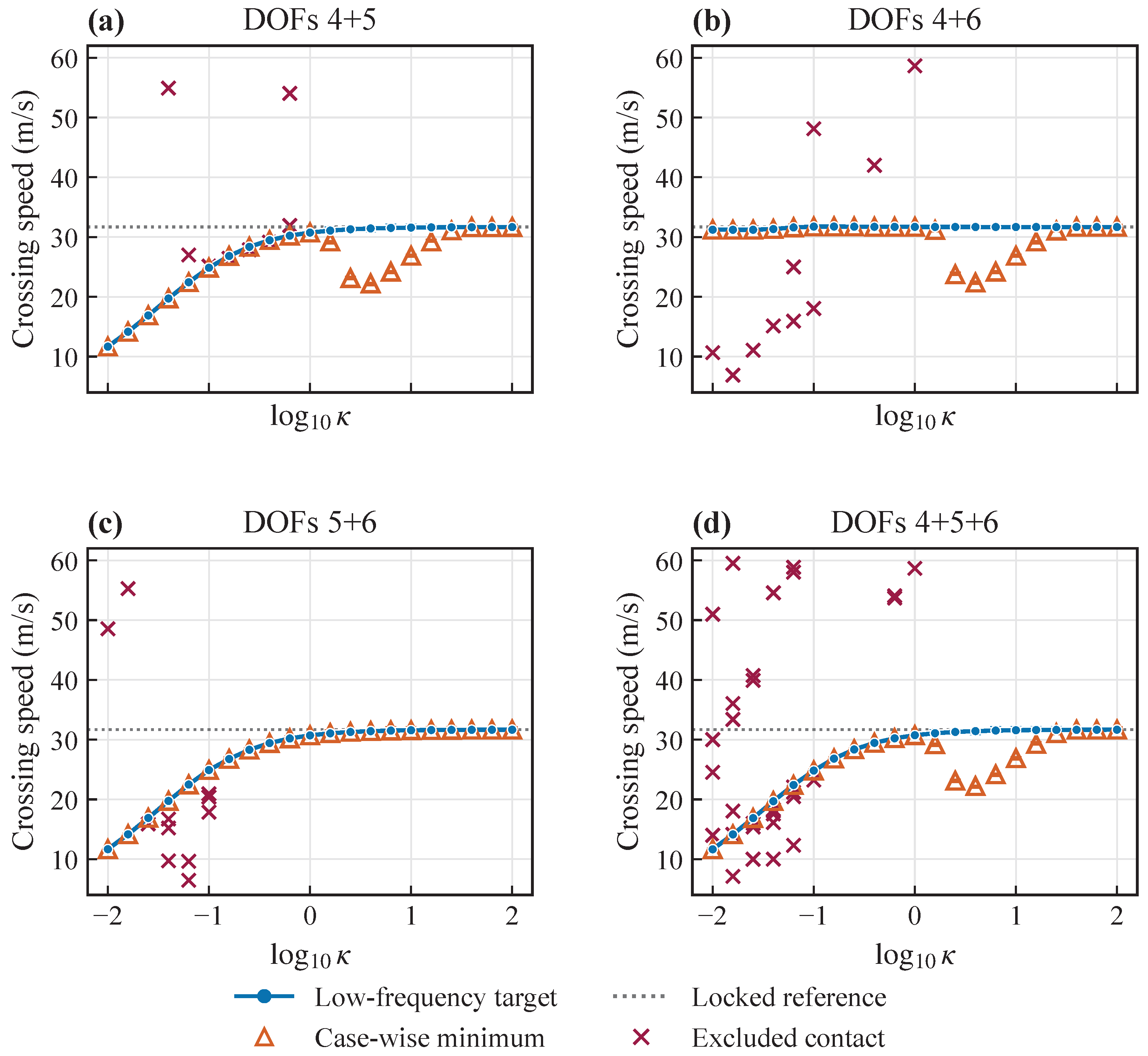
The four multi-channel families impose one common on every active rotation at both interfaces. They are one-dimensional co-variation paths rather than a factorial design, so independent interaction coefficients cannot be inferred. Figure 11 maintains the distinction between the low-frequency target sequence and unconnected secondary candidates.
Figure 11.
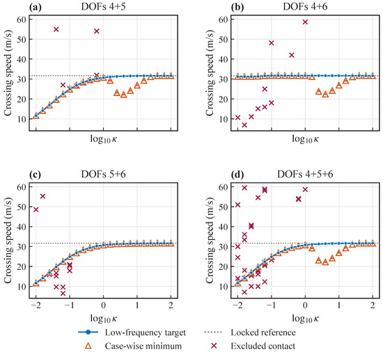
Locked-reference-oriented low-frequency target paths and case-wise minimum candidates for (a) DOF 4+5, (b) DOF 4+6, (c) DOF 5+6, and (d) DOF 4+5+6. Connected blue circles denote MAC-validated targets; open orange triangles denote case-wise minima, including coincident selections shown as nested symbols. Secondary candidates and excluded diagnostic crosses are not joined across cases. All four panels use the same ordinate range (4–62 m/s) and tick spacing, retaining the full set of displayed diagnostic contacts.
The sampled DOF 4+5 and DOF 5+6 paths exhibit target-migration patterns comparable to the single-channel DOF 5 path, spanning 11.662–31.662 and 11.669–31.662 m/s, respectively. For DOF 5+6, the two reported selections coincide throughout. For DOF 4+5, they differ in seven cases, indicating that inclusion of DOF 4 adds secondary contacts even though it does not change the family-level speed extrema. The DOF 4+6 path similarly preserves the nearly locked low-frequency target sequence of DOF 4 while retaining lower-speed secondary contacts in seven cases.
The three-channel target branch spans 11.661–31.662 m/s at 0.854–2.393 Hz and differs from the secondary minimum in 7 of 21 cases. Its low-stiffness sequence is 11.661, 14.147, and 16.876 m/s in Cases 01–03, with paired frequencies of 0.854, 1.038, and 1.242 Hz. A dedicated 0.25 m/s refinement places the Case 02 contact in the 14.00–14.25 m/s bracket; all 20 adjacent MAC segments over 10–15 m/s are strong-unique, with minimum raw and deformation MAC values of 0.9992 and 0.9995 and a minimum competitor margin of 0.408. Full-speed MAC traces and geometric stiffness midpoints associate these contacts with the branch that approaches the locked response; the previously selected 34.920 and 41.567 m/s contacts belong to a different competing branch. The corrected target speed and frequency increase continuously and monotonically along the sampled common-stiffness path. The sampled three-channel path, therefore, exhibits a target-migration pattern comparable to the single-channel DOF 5 path, without establishing a universal interaction law.
4.5. Unequal-Interface Cases
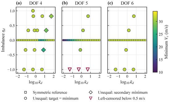
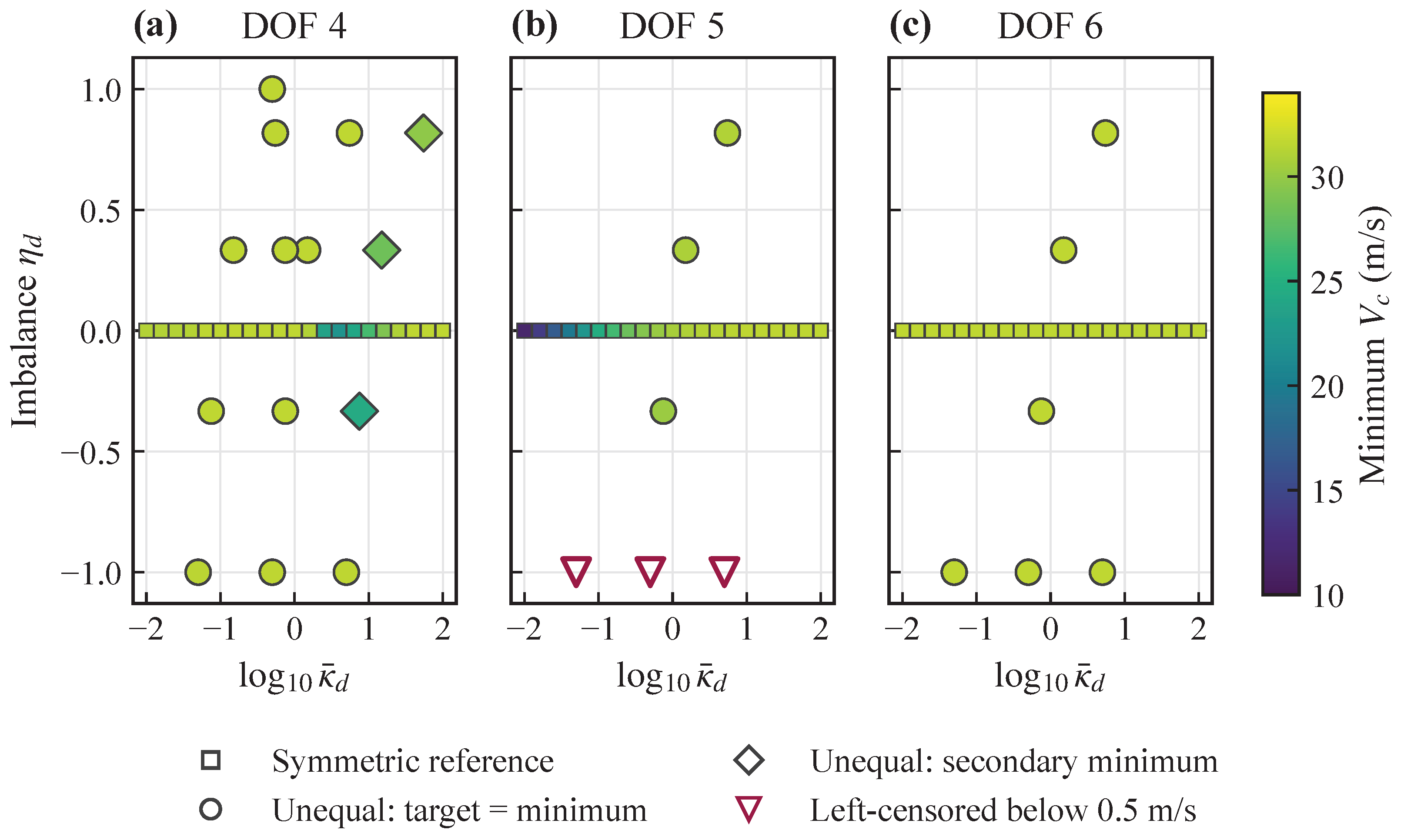
The discrete unequal-interface sets in Figure 12 use the mean-stiffness and imbalance coordinates of Equation (9). Existing symmetric single-channel results are added at , with . These reference points show the symmetric response over the same normalization range. Mean stiffness and imbalance were not varied independently, so the unequal results remain case-wise comparisons rather than a fitted asymmetry law.
Figure 12.
Symmetric and unequal-interface outcomes for (a) DOF 4, (b) DOF 5, and (c) DOF 6. The horizontal row of 21 colored squares at shows the symmetric reference cases in each panel. Color denotes the lowest persistence-supported in assigned cases; diamonds identify cases with an additional lower-speed candidate, and open downward triangles identify left-censoring at 0.5 m/s. The unequal stiffness pairs are listed in Table 15; the symmetric grid is defined in Section 2.3.
For unequal DOF 4 stiffness, the case-wise low-frequency target remains at 31.523–31.737 m/s and 2.394–2.416 Hz, whereas a secondary candidate reaches 24.517 m/s in three of the 14 cases. This reproduces the single-channel DOF 4 pattern without isolating imbalance as its cause. In the three most flexible unequal DOF 5 configurations, oscillatory histories remain on the positive-g side at 0.5 m/s and at the next two samples. They are, therefore, left-censored below 0.5 m/s rather than assigned a later contact. The remaining three DOF 5 cases give coincident selections at 30.278–31.142 m/s and 2.282–2.351 Hz. After two near-neutral contacts are excluded, all six unequal DOF 6 cases remain near 31.672 m/s and 2.394 Hz. These results establish differences among the sampled stiffness pairs, not an independent law of left–right asymmetry.
Table 15 lists the prescribed unequal stiffness pairs. Table 16 consolidates the locked, limiting, and unequal-interface outcomes.
Table 15.
Prescribed unequal-interface stiffness pairs . Each column lists one rotation channel; all other rotations remain locked. Case numbers follow their order within that family.
Table 16.
Case-wise results for the locked, limiting, and discrete unequal-interface sets. Target-nearest values are selected independently within each case; no reference path is defined across these sets. Frequencies are given in Hz and speeds in m/s.
4.6. Representative Damping Histories
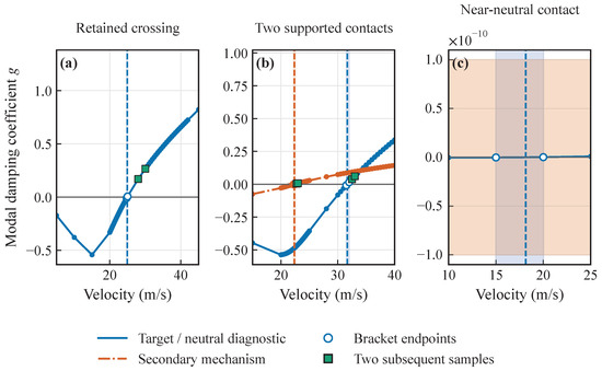
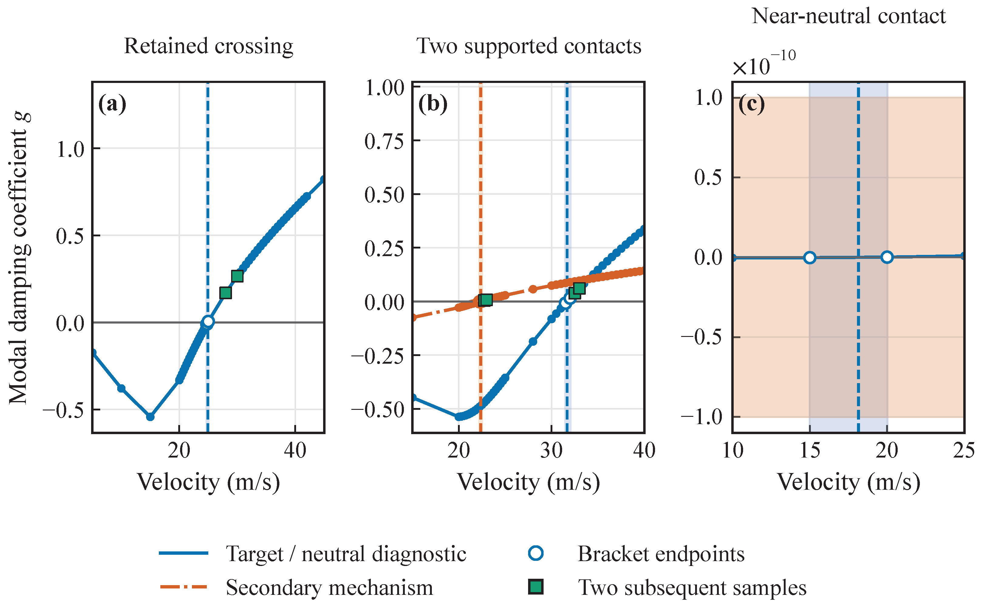
Figure 13 shows how the evidence classes arise from sampled damping histories. The endpoints display the actual interpolation brackets, and the two subsequent samples implement the finite-history persistence requirement.
Figure 13.
Representative sampled damping histories: (a) a retained low-frequency crossing at the sixth stiffness point of the symmetric DOF 5 path; (b) low- and higher-frequency supported contacts at the fourteenth point of the symmetric DOF 4 path and (c) a neutral-band diagnostic in the first unequal-DOF 6 case. Blue vertical shading marks the sampled velocity bracket for the target or near-neutral diagnostic contact; orange vertical shading marks the secondary-contact bracket in (b). Dashed lines mark interpolated contacts, green squares mark subsequent samples, and the orange horizontal band in (c) denotes .
Panel (a) demonstrates the persistent sign transition underlying the low-frequency target sequence. Panel (b) shows why the secondary audit is retained: two branch histories satisfy the scalar evidence rule in one configuration but occupy different frequency regions. Panel (c) illustrates a contact whose endpoints remain within the neutral band. Together, the histories show that, among the prescribed single-channel paths, the DOF 5 path exhibits the largest migration of the tracked low-frequency target, the DOF 6 path changes that target least within the adopted resolution, and the DOF 4 path introduces the clearest lower-speed competition.
4.7. Limitations and Interpretation
The results quantify a particular low-frequency response within a linear model about the undeformed, unloaded reference configuration. Zero structural damping supplies a common baseline, with precedent in aeroelastic studies such as Thomas et al. [22]; aerodynamic damping remains included. This assumption is not a measured property of the assembly and does not establish conservative crossing speeds.
The interfaces include rotational stiffness with constrained translations and inactive rotations. Joint damping, translational compliance, free-play, friction, preload and manufacturing variability are omitted, as are nonlinear aerodynamic and structural effects. Linear weak-stiffness and fully released cases do not represent a free-play dead band or contact engagement. Free-play is reserved for subsequent nonlinear research. No gravity load or aeroelastic trim solution precedes the present flutter analysis; trim-induced changes in geometry, tangent stiffness and aerodynamic operating point are consequently unquantified. Load-induced deformation and geometric nonlinearity are the subject of ongoing work, not evidence for the current results.
The numerical-setting checks and complex-MAC audit support calculations and modal associations within this model. The selected cross-solver comparison adds evidence for relative stiffness effects while leaving an approximately 10.2% low-frequency speed discrepancy. No experimental measurements or calibrated joint-damping data are available. The crossings are, therefore, model-specific, branch-specific sensitivity results, rather than an experimentally validated global boundary or a prediction about a specified trimmed flight equilibrium. Their interpretation remains conditional on the fixed flight parameters, sampled ranges and documented modal coordinates; persistence of the trends when the omitted physical effects are included has not been established.
5. Conclusions
Within the investigated linear model and prescribed stiffness paths, rotation about the spanwise wingtip-joint axis (DOF 5) produces the largest migration of the monitored low-frequency aeroelastic response. Changes in dry frequencies and interface-spring participation provide structural context for this sensitivity. The other two connection channels have much weaker effects on the tracked response, but DOF 4 can introduce a lower-speed competing branch. Joint-stiffness selection, therefore, requires consideration of candidate competition as well as target migration.
Unequal left–right stiffness combinations alter the sampled candidate ordering. Because mean stiffness and imbalance were not varied independently, these comparisons do not establish a universal asymmetry law. The released-DOF 5 diagnostics further distinguish non-oscillatory mechanism-related growth from oscillatory crossings; the original target has no uniquely assigned continuation at complete release.
The five-case cross-solver comparison supports the selected relative trends while leaving an approximately 10.2% low-frequency speed discrepancy. The findings remain conditional on the undeformed, unloaded, zero-structural-damping reference model and the numerical scope described in Section 4.7. Application to manufactured joints or trimmed flight conditions requires further characterization and validation.
Author Contributions
Conceptualization, Y.B. and J.Z.; methodology, Z.Z., C.Z., Z.Y. and Y.B.; software, Z.Z.; validation, Z.Z., C.Z. and Z.Y.; formal analysis, Z.Z., C.Z. and Z.Y.; investigation, Z.Z., C.Z. and Z.Y.; data curation, Z.Z.; visualization, Z.Z.; resources, Y.B.; funding acquisition, Y.B.; supervision, J.Z.; writing—original draft preparation, Z.Z.; writing—review and editing, Z.Z. and J.Z. All authors have read and agreed to the published version of the manuscript.
Funding
This research was funded by the National Natural Science Foundation of China, grant number 12202442, and the China Scholarship Council, grant numbers 202504910211, 202504910212, and 202504910353. The funders had no role in the design of the study; in the collection, analysis, or interpretation of data; in the writing of the manuscript; or in the decision to publish the results.
Institutional Review Board Statement
Not applicable.
Informed Consent Statement
Not applicable.
Data Availability Statement
The numerical results supporting the conclusions are reported in the article.
Conflicts of Interest
The authors declare no conflicts of interest.
References
- Patil, M.J.; Hodges, D.H.; Cesnik, C.E.S. Nonlinear Aeroelasticity and Flight Dynamics of High-Altitude Long-Endurance Aircraft. J. Aircr. 2001, 38, 88–94. [Google Scholar] [CrossRef] [Scilit] [PubMed]
- Cesnik, C.E.S.; Senatore, P.J.; Su, W.; Atkins, E.M.; Shearer, C.M. X-HALE: A Very Flexible Unmanned Aerial Vehicle for Nonlinear Aeroelastic Tests. AIAA J. 2012, 50, 2820–2833. [Google Scholar] [CrossRef] [Scilit]
- Patterson, M.D.; Quinlan, J.R.; Fredericks, W.J.; Tse, E.; Bakhle, I. A Modular Unmanned Aerial System for Missions Requiring Distributed Aerial Presence or Payload Delivery. In Proceedings of the 55th AIAA Aerospace Sciences Meeting, Grapevine, TX, USA, 9–13 January 2017. [Google Scholar] [CrossRef] [Scilit]
- Montalvo, C.; Costello, M. Meta Aircraft Flight Dynamics. J. Aircr. 2015, 52, 107–115. [Google Scholar] [CrossRef] [Scilit]
- Cooper, J.R.; Rothhaar, P.M. Dynamics and Control of In-Flight Wingtip Docking. J. Guid. Control Dyn. 2018, 41, 2327–2337. [Google Scholar] [CrossRef] [Scilit] [PubMed]
- Carithers, C.; Montalvo, C. Experimental Control of Two Connected Fixed Wing Aircraft. Aerospace 2018, 5, 113. [Google Scholar] [CrossRef] [Scilit]
- Meng, Y.; An, C.; Xie, C.; Yang, C. Conceptual Design and Flight Test of Two Wingtip-Docked Multi-Body Aircraft. Chin. J. Aeronaut. 2022, 35, 144–155. [Google Scholar] [CrossRef] [Scilit]
- Zhu, E.; Zhou, Z.; Li, H. Modal Analysis and Flight Validation of Compound Multi-Body Aircraft. Aerospace 2023, 10, 442. [Google Scholar] [CrossRef] [Scilit]
- An, C.; Huo, G.; Meng, Y.; Xie, C.; Yang, C. Aerodynamic Modeling Methods and Influence of Layout Parameters for Wingtip-Hinged Multi-Body Combined UAV. Acta Aeronaut. Astronaut. Sin. 2024, 45, 629587. (In Chinese) [Google Scholar] [CrossRef]
- Tang, D.; Dowell, E.H. Theoretical and Experimental Aeroelastic Study for Folding Wing Structures. J. Aircr. 2008, 45, 1136–1147. [Google Scholar] [CrossRef] [Scilit]
- Zhao, Y.; Hu, H. Parameterized Aeroelastic Modeling and Flutter Analysis for a Folding Wing. J. Sound Vib. 2012, 331, 308–324. [Google Scholar] [CrossRef] [Scilit]
- Qi, W.; Wu, S.; Tian, S. Flutter Characteristics of a Modified Z-Shaped Folding Wing Using a New Non-Intrusive Model. Aerospace 2024, 11, 425. [Google Scholar] [CrossRef] [Scilit]
- Liu, C.; An, C.; Xie, C.; Zhang, X.; Yang, L. Experimental and Numerical Flutter Analysis of a Folding Fin with Multiple Asymmetric Free-Plays. Chin. J. Aeronaut. 2024, 37, 332–348. [Google Scholar] [CrossRef] [Scilit]
- Dhital, K.; Nguyen, A.T.; Han, J.H. Aeroelastic Modeling and Analysis of Wings in Proximity. Aerosp. Sci. Technol. 2022, 130, 107955. [Google Scholar] [CrossRef] [Scilit]
- Albano, E.; Rodden, W.P. A Doublet-Lattice Method for Calculating Lift Distributions on Oscillating Surfaces in Subsonic Flows. AIAA J. 1969, 7, 279–285, Correction in AIAA J. 1969, 7, 2192. [Google Scholar] [CrossRef] [Scilit] [PubMed]
- Hassig, H.J. An Approximate True Damping Solution of the Flutter Equation by Determinant Iteration. J. Aircr. 1971, 8, 885–889. [Google Scholar] [CrossRef] [Scilit]
- Eldred, M.S.; Venkayya, V.B.; Anderson, W.J. New Mode Tracking Methods in Aeroelastic Analysis. AIAA J. 1995, 33, 1292–1299. [Google Scholar] [CrossRef] [Scilit] [PubMed]
- Hang, X.; Fei, Q.; Su, W. On Tracking Aeroelastic Modes in Stability Analysis Using Left and Right Eigenvectors. AIAA J. 2019, 57, 4447–4457. [Google Scholar] [CrossRef] [Scilit]
- McDonnell, T.; Ning, A. Reliable Mode Tracking for Gradient-Based Optimization with Dynamic Stability Constraints. AIAA J. 2023, 61, 505–509. [Google Scholar] [CrossRef] [Scilit]
- Yu, Q.; Damodaran, M.; Khoo, B.C. Predicting Wing–Pylon–Nacelle Configuration Flutter Characteristics Using Adaptive Continuation Method. Adv. Aerodyn. 2023, 5, 21. [Google Scholar] [CrossRef] [Scilit]
- Ang, E.H.W.; Ng, B.F. Stability Analysis of Body-Freedom Flutter in Flying Wing Unmanned Aerial Vehicles. AIAA J. 2026, 64, 946–954. [Google Scholar] [CrossRef] [Scilit]
- Thomas, J.P.; Dowell, E.H.; Hall, K.C. A Harmonic Balance Approach for Modeling Three-Dimensional Nonlinear Unsteady Aerodynamics and Aeroelasticity. In Proceedings of the ASME International Mechanical Engineering Congress and Exposition, New Orleans, LA, USA, 17–22 November 2002. paper IMECE-2002-32532. [Google Scholar]

Disclaimer/Publisher’s Note: The statements, opinions and data contained in all publications are solely those of the individual author(s) and contributor(s) and not of MDPI and/or the editor(s). MDPI and/or the editor(s) disclaim responsibility for any injury to people or property resulting from any ideas, methods, instructions or products referred to in the content. |
© 2026 by the authors. Licensee MDPI, Basel, Switzerland. This article is an open access article distributed under the terms and conditions of the Creative Commons Attribution (CC BY) license.