1. Introduction
High-speed drives are essential in diverse fields, ranging from industrial manufacturing (milling machines, lathes) to laboratory equipment, such as centrifuges. In medical applications, these systems are employed in the separation of blood samples and other biological fluids. Low-power variants are widely applied in portable power tools, including drills, engravers, grinders, and saws. Furthermore, significant applications are found in the aviation and automotive industries, where very high rotational speeds are required for turbochargers, aircraft windshield wipers, and starter motors [
1,
2,
3,
4,
5,
6,
7,
8,
9,
10]. These drives are also used in household appliances, such as vacuum cleaners, to reduce their size and acoustic noise [
11]. In the textile industry, they are primarily applied for spindle actuation [
1,
12,
13].
Several types of electric motors are employed in high-speed drives systems, including permanent magnet motors, hysteresis motors and SRMs [
2,
3,
14]. Permanent magnet motors, most commonly implemented as BLDC motors, can achieve very high rotational speeds with an appropriate design consideration. The challenge with this type of motor lies in the mounting of the magnets, which are subjected to very high centrifugal forces in the rotors. Nevertheless, due to their high power density, they are dominant in drives for small flying objects such as drones [
2,
15]. For larger drives and higher speeds, it is often necessary to mount the magnets in channels inside the rotor.
Hysteresis motors are much more resistant to damage resulting from high rotational speeds. A key advantage of hysteresis motors is their low acoustic noise emissions. Nevertheless, their disadvantages include significant rotor heating and low torque at low speeds, which significantly limits their applicability in many practical applications [
16,
17,
18,
19,
20].
Switched reluctance motors do not exhibit these specific disadvantages [
21,
22,
23]. They feature a robust rotor made of laminated electrical steel, offering high durability and relatively high efficiency [
24,
25]. Their main drawback is the high vibration and noise levels resulting from the pulsed power supply and the salient-pole rotor design. These effects can be mitigated through advanced control strategies [
21,
22,
25,
26,
27,
28,
29].
SRMs require specialised converters that switch the phase supply voltage depending on the rotor angular position [
23,
24,
30]. To achieve correct operation, it is necessary to make the supply voltage and the angular ranges of the phase supply dependent on the motor’s operating point. At high speeds, precise control of the phase supply, and in particular the determination of rotor position and speed, requires the controller to execute multiple complex functions with very low latency. Therefore, the controller must ensure very high algorithm execution speed [
30,
31,
32]. Expanding the control algorithm with additional functionalities, such as vibration and noise reduction, and calculating the drive’s mathematical model, in the case of microcontrollers, leads to longer control cycles.
A significant portion of a microcontroller’s control algorithm is implemented in interrupt handling routines. As drive speed and control accuracy increase, the percentage of processor time required to perform basic functions increases. Compared to typical low-speed drive systems, the interrupt generation frequency can increase by over a hundred-fold. Therefore, in high-speed, adjustable-speed drives, the time required to execute interrupt handling routines increases proportionally with the speed. In microprocessor controllers, ultra-high speed capabilities are typically achieved at the expense of control precision. In such cases, any additional expansion of the control algorithm can slow down the execution of the control algorithm.
For this reason, a good alternative to the control program may be the implementation of the control algorithm in the form of specialized hardware structures that operate concurrently. In such systems, adding new functionalities does not degrade performance, provided that the execution time remains within the maximum delay of existing modules. Field-programmable gate arrays (FPGAs) provide such capabilities [
20,
33,
34,
35,
36,
37,
38]. The concurrent architecture ensures that execution speed and temporal determinism remain largely independent of the number of implemented tasks.
The scientific objective of this paper is to determine whether, and to what extent, the controller architecture itself introduces limitations on SRM drive operation at high rotational speeds, and to identify the maximum achievable speed range resulting from these hardware-induced constraints.
2. Properties of Switched Reluctance Motors
Due to the simple rotor structure, made as a stack of sheets, switched reluctance motors are characterised by high mechanical strength and resistance to centrifugal forces. In this respect, they are similar to hysteresis motors [
18,
19]. Nevertheless, due to the method of obtaining electromagnetic torque, their rotors possess salient rotor teeth, which introduce a clear dependence of magnetic reluctance on the rotor angle.
The electromagnetic torque of this type of motor is proportional to the difference between the maximum and minimum values of magnetic reluctance. When a phase is supplied with power within a specific angular range, the rotor tends to achieve the position of minimum magnetic reluctance. To maintain continuous motion, the supply voltage to a phase can be switched off before this position is reached, while simultaneously switching on the supply voltage to the next phase. It is also possible to specify an angular range that positions the rotor in the position of minimum magnetic reluctance [
14,
23,
30].
This enables these motors to achieve their rated torque when they are operated at low speeds and during positioning. In this speed range, it is necessary to limit the current or reduce the supply voltage. The phase is therefore supplied as a series of pulses. In practical operation, this occurs between zero and the rated speed. Above the rated speed, when supplied with the rated voltage, the phases are often supplied with single pulses, and the speed depends on the commutation angles [
21,
22,
23,
24,
39,
40,
41].
A further increase in rotational speed can be achieved by increasing the supply voltage of the motor phases. Particularly important in this case is the increase in voltage at the initial stage of the phase supply cycle and the return of energy from the windings, after the phase supply is switched off, to a higher voltage source. This accelerates the rise and fall of phase currents. As a result, the average current value is increased in the angular range where the electromagnetic torque is positive. Conversely, this limits the time of phase current flow in the angular range where the electromagnetic torque is negative.
Therefore, a number of different converter topologies have been developed to power SRM motors [
23,
24]. SRMs have mechanical characteristics similar to those of series motors, but their properties can be adjusted over a wide range by changing the commutation angles. The electronic converter, acting as an electronic sparkless commutator, must enable the appropriate selection of the phase supply angle ranges to the motor operating point [
21,
25,
26,
42].
The efficiency of SRM motors is slightly lower than that of BLDC motors, but they do not contain rare-earth magnets. It should also be noted that the mechanical strength of BLDC motor rotors is lower than that of SRM motors. Therefore, for very high speeds, complex rotor designs are required in permanent magnet motors, and the magnets are mounted below the rotor surface.
Unlike the converters that power BLDC motors, to achieve correct operation of an SRM motor, it is necessary to adjust the commutation angles according to the desired operating point. For high-speed drives, the controller must decode very quickly the position, measure currents and instantaneous speed, and control the signals that activate the phase power supply.
The main goal of this work was to analyse the feasibility of implementing an SRM control system based on a programmable logic device. Using this type of system eliminates the need for sequentially executed microcontroller programs, where the introduction of any additional functionality slows down the control algorithm.
Programmable logic devices enable the implementation of a controller as specialised logic circuits in which various controller functionalities operate concurrently, and significantly faster than in a microprocessor-based software implementation. With this controller structure, only the basic control path modules are critical to the controller’s speed. The remaining modules operate concurrently and therefore do not affect the maximum execution speed of the algorithm.
Due to the hardware implementation of the functional modules of the main control path, the delays introduced by the controller are relatively small compared to those observed in microprocessor controllers. This work determined the maximum theoretical drive speed at which the controller can operate correctly, with high commutation angle resolution.
This study aimed to determine the maximum theoretical operating speed of the drive at which the controller can function correctly while maintaining high angular position measurement resolution of the rotor. For this purpose, a functional analysis of the control system was performed, and the key modules and signal paths having the greatest impact on the execution speed of the control algorithm were identified. Simulation and experimental investigations were conducted to determine the delays introduced by these modules, and the maximum delay introduced by the primary signal path was established. Based on these results, the maximum theoretical rotational speed at which the control system is capable of executing the control algorithm was determined.
3. Functional Analysis of the SRM Control System
Proper relationship between commutation angles and rotational speed enables optimisation of drive performance at specific operating points, for example, to maximise efficiency or minimise acoustic noise [
43]. In SRM drives, the operating points corresponding to maximum power, maximum efficiency, and minimum torque ripple generally differ. Therefore, achieving both high efficiency and high output power requires a compromise and careful optimisation of control parameters. Reducing electromagnetic torque ripple and the associated acoustic noise typically requires shaping of phase current waveforms through supply voltage modulation. Consequently, multipulse voltage excitation is often applied; however, this approach increases commutation losses. Furthermore, operation at high rotational speeds with multipulse excitation requires accurate determination of control parameters.
The angular range of phase excitation is defined by the resolution of the rotor position measurement. Various sensor-based and sensorless techniques can be employed to estimate rotor position. Sensorless methods rely on indirect measurements, such as phase inductance variation with rotor position, and are generally less accurate than sensor-based approaches. In practical SRM drives, incremental encoders are most commonly used. These can be mounted externally on the motor shaft or integrated directly into the motor housing. At high rotational speeds, integrated encoders are preferable due to potential alignment issues associated with external sensors. Higher encoder resolution enables more precise adjustment of phase excitation angles. Encoder signals are also used for instantaneous speed estimation, which is required for closed-loop control.
Accurate determination of rotor position is a key challenge in SRM drives. The required phase excitation angle range depends on the number of motor phases. For a typical two-phase SRM, a minimum conduction interval of 90 degrees (electrical) is required to ensure continuous torque production. For three-phase and four-phase machines, this interval decreases to approximately 30 and 15 degrees, respectively. When using a standard encoder with a resolution of 360 pulses per revolution, the angular resolution becomes progressively coarser for motors with a higher number of phases. Improved accuracy can be achieved by applying advanced position estimation techniques or higher-resolution sensors.
Another important aspect is voltage regulation within the phase excitation interval. When PWM is applied, the number of voltage pulses per conduction cycle decreases as speed increases. At high speeds, single-pulse operation is commonly used. However, additional voltage modulation may still be required to minimise torque ripple. Therefore, the PWM switching frequency should be sufficiently high to generate multiple supply voltage pulses within the excitation interval, enabling accurate shaping of the phase current waveform.
Appropriate phase current measurement frequency is also essential. The rate of current rise depends on the instantaneous phase inductance and reaches its maximum when the rotor and stator teeth are fully unaligned. The sampling frequency must, therefore, ensure a sufficiently fast controller response to prevent current overshoot beyond permissible limits. Additional protection can be implemented at the hardware level by directly coupling transistor drivers with current sensors, allowing rapid overcurrent response independent of the controller.
For C-dump converter topologies, measurement of the capacitor voltage is also required. High sampling speeds are necessary to maintain the voltage within predefined limits, which depend on the rotational speed. Based on the measured voltage, switching devices are controlled to limit the maximum voltage during capacitor charging and the minimum voltage during discharge. The voltage variation rate is determined by the phase current magnitude and the capacitance.
4. Structure of a Controller Based on an FPGA Programmable Logic Device
The presented drive system consists of an FPGA-based control module, a driver module, a power transistor module, and a power supply. Depending on the converter topology, the output transistors can operate in various configurations. The simplest and most commonly used solution is the asymmetric H-bridge converter. For high-speed operation, more advanced converter topologies, such as C-dump or multilevel converters, can be employed [
24,
31,
44,
45,
46,
47]. However, these configurations require more sophisticated control algorithms, including the control of additional switching devices and the measurement of extra parameters affecting the control process.
Multilevel converters are generally more expensive due to the large number of power transistors they require. A more cost-effective alternative is the C-dump converter. In this topology, the C-dump capacitor acts as a dynamic energy buffer, whose voltage can be adjusted by the control system according to the motor operating conditions.
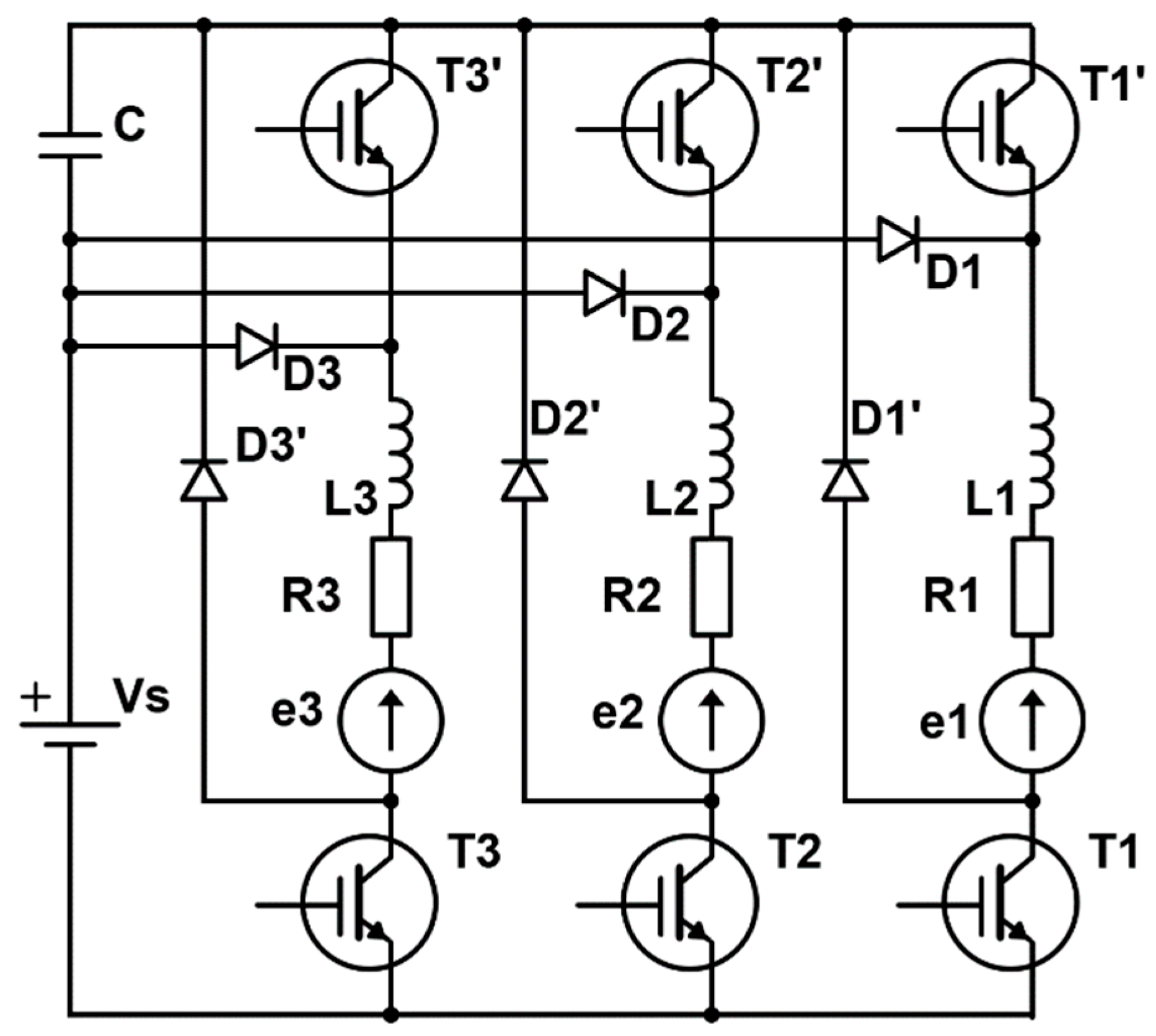
To achieve high rotational speeds, the converter configuration shown in
Figure 1 is applied. In addition to regulating the supply voltage from zero to its rated value and adjusting the commutation angles, this topology allows the voltage to be boosted to expand the drive’s power and speed range. The C-dump capacitor is charged using energy recovered from the phase windings after phase excitation is switched off. Increasing the voltage, particularly during the initial excitation interval, enables approximately a threefold increase in speed while maintaining the rated output power. A detailed description of this system is provided in [
48].
The driver module incorporates signal conditioning circuits and measurement units. For an asymmetric H-bridge converter, the measured quantities include phase currents and supply current. In C-dump converter configurations, additional measurements of the C-dump capacitor voltage are necessary.
The power supply system provides the voltages needed to power the motor, drivers, sensors, and control system. The motor power supply subsystem consists of a rectifier and filter capacitors. In drives with regenerative braking capability, it also includes a feedback circuit that returns energy to the supply source. Furthermore, the power supply delivers regulated voltages to the controller in accordance with component requirements.
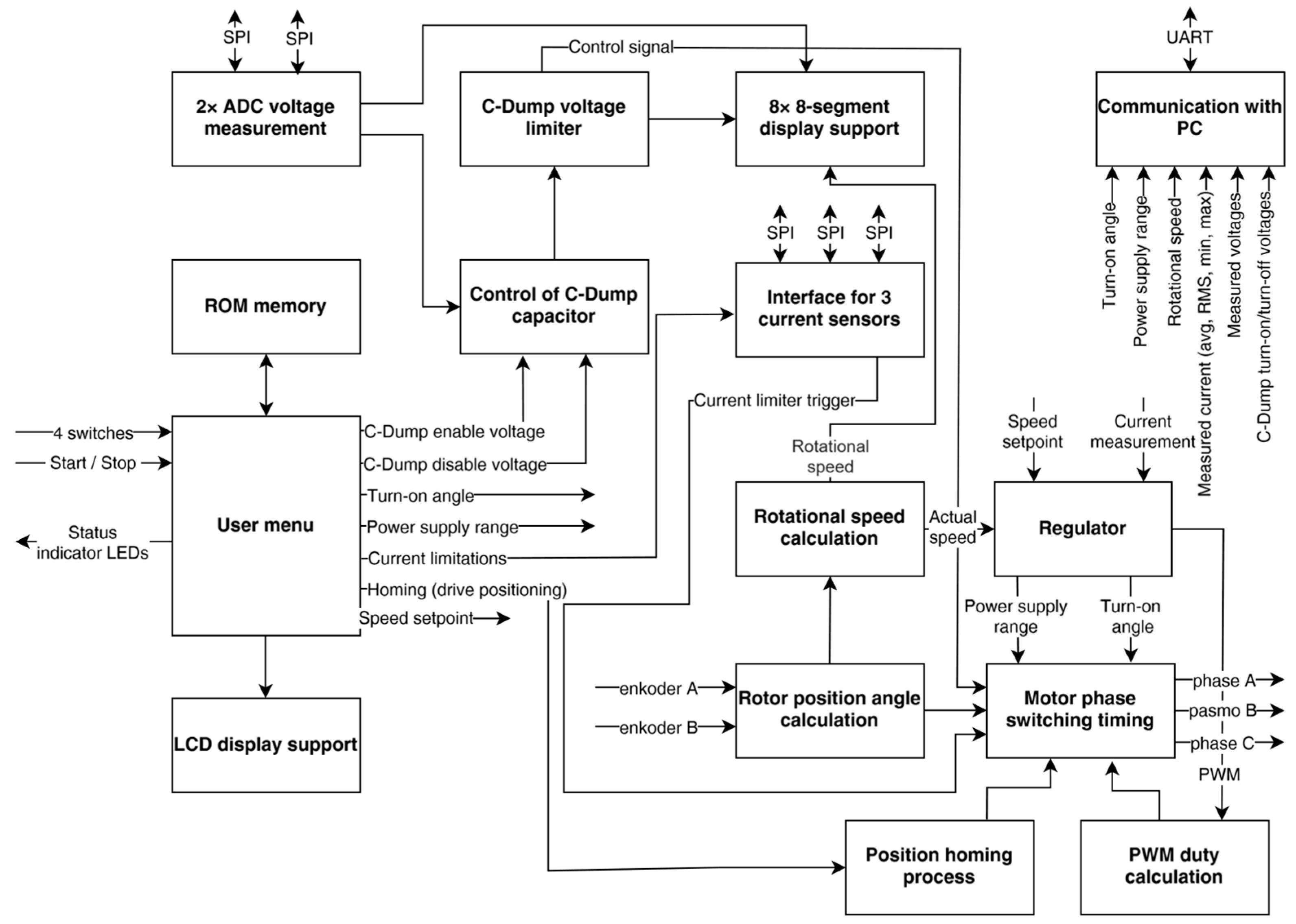
In the proposed system, the controller is implemented using an FPGA device. To minimize processing delays at high rotational speeds, parallel hardware structures are used instead of sequential microcontroller-based software control. The controller functionality can be divided into two main groups: time-critical modules directly involved in the control process and auxiliary modules that do not influence real-time operation, such as user interface and communication modules. The resulting block diagram, derived from the functional analysis, is shown in
Figure 2.
The controller comprises the following main functional modules: a rotor angular position estimation module, a phase sequence decoder, current and voltage measurement modules, a speed estimation module, a PWM generator module with current limiting, and a control module. Depending on the applied control strategy, additional modules may be incorporated, such as a mathematical model computation unit. All core modules must execute their functions within each drive control cycle, as any excessive latency may degrade system performance or destabilize the control process.
4.1. PWM Generator Module
PWM is applied to regulate the supply voltage to the motor phases. The PWM signal frequency is set to 20 kHz. Therefore, the voltage update period is 50 µs or an integer multiple of this value. The PWM generator is implemented using a counter clocked by a prescaler and digital comparator. The module features a 16-bit input port for the duty-cycle signal and a single-bit output port generating the PWM signal. The designed architecture provides a PWM resolution of 1000 discrete levels.
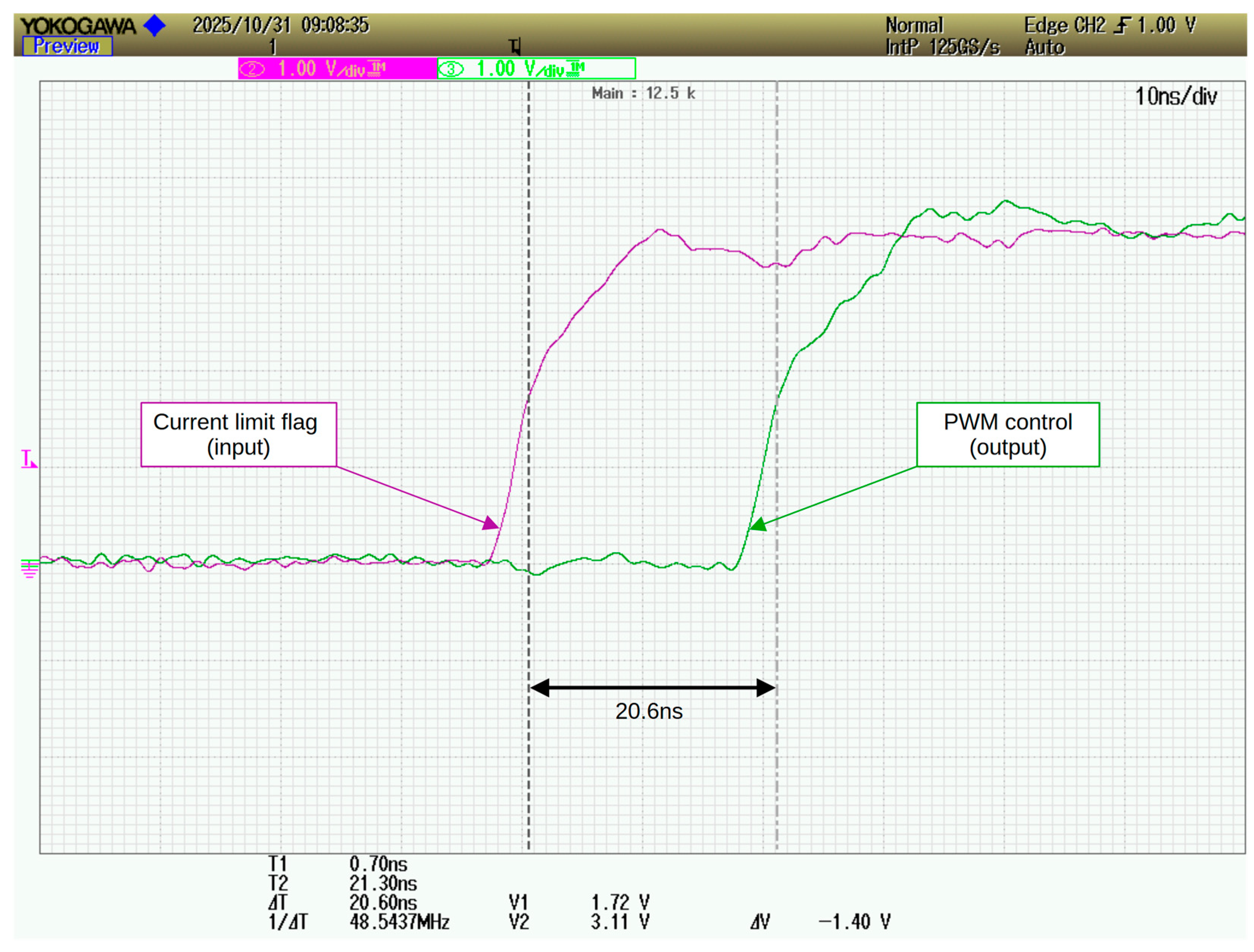
An additional input is included for the current limiting circuit. The PWM output signal is connected to an AND gate, the other input of which receives the inverted signal from the current limiting module. When the phase current exceeds the predefined threshold, the second input of the gate is forced low, thereby blocking the PWM pulses.
Synthesis results indicate a maximum PWM rising-edge delay of less than 5 ns relative to changes in the input control signal. This delay is mainly caused by the prescaler and the reduced clock frequency of the generator. Experimental measurements with the module connected to the FPGA I/O ports revealed a total propagation delay of 20.6 ns, as shown in
Figure 3.
The module has a two-bit incremental encoder input port and an 11-bit output port for the rotor angular position value. The module operates synchronously to a 10 ns system clock. On the synchronization pulse edge, the module checks for a change in encoder state, then determines the direction of rotation and updates the position counter.
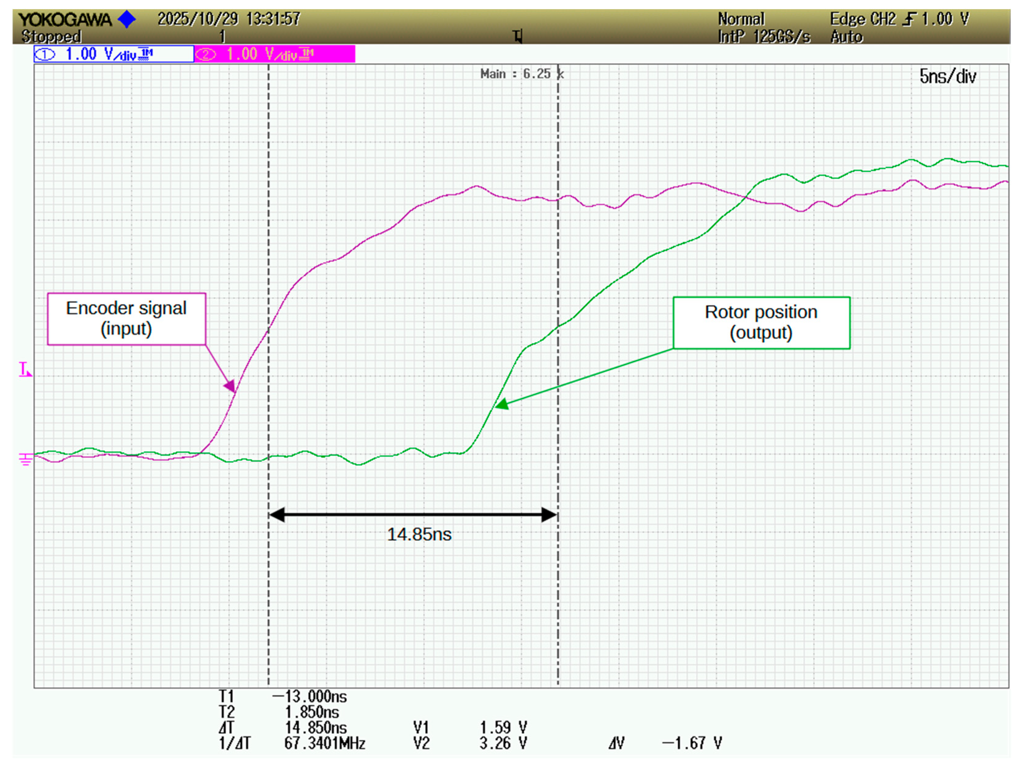
The resulting rotor angular position value is transmitted via the output port. Detection of all state changes occurs in both channels at 360-pulse/rev and the system can detect rotor position changes every 0.25 degrees. The delay time of the output signals relative to the input signals obtained during synthesis is 10 ns.
Experimental measurements, including the FPGA I/O port delays, revealed a total delay of 15 ns, as shown in
Figure 4.
Assuming a rotor position detection frequency of half the system clock frequency (50 MHz) and a measurement resolution of 0.25 degrees, the module can theoretically operate at speeds exceeding 2.5 million rpm. Therefore, this module does not impose a limit on the maximum speed of the drive.
4.2. Instantaneous Speed Measurement Module
This module is implemented as a process within the rotation angle determination module and has a two-bit encoder signal input. The measurement is synchronised with the PWM signal period. The output of this module is a 16-bit port. The module counts the number of state changes of both encoder channels within 1 ms.
Theoretically, speed can be measured in a range from approximately 40 rpm to over 2.7 million rpm. The instantaneous speed signal is utilized by the controller module and can also be used, for example, to adjust calculations in the drive’s mathematical model, depending on the control strategy. Since the instantaneous speed value is not used in the user interface, it is expressed directly as the number of encoder pulses per millisecond. This module does not restrict the controller’s maximum operating speed.
4.3. Average Speed Measurement Module
The average speed measurement module processes output from the instantaneous speed measurement module by averaging the results over 256 measurements cycles. The display module then converts this value into rpm. This module does not affect the operation of the control chain. The average speed value is used in the user interface module only to inform the operator of the current motor speed. Delays resulting from this module’s operation are irrelevant to the control process.
4.4. Current Measurement Module
Infineon TLI4970 Hall-effect sensors with a serial SPI interface are used for current sensing. The measurement is performed with 13-bit resolution, and results are read as a 16-bit values. The sensor updates its output at a maximum frequency of 80 kHz. The phase current measurement module consists of three independent SPI interfaces clocked at 3 MHz.
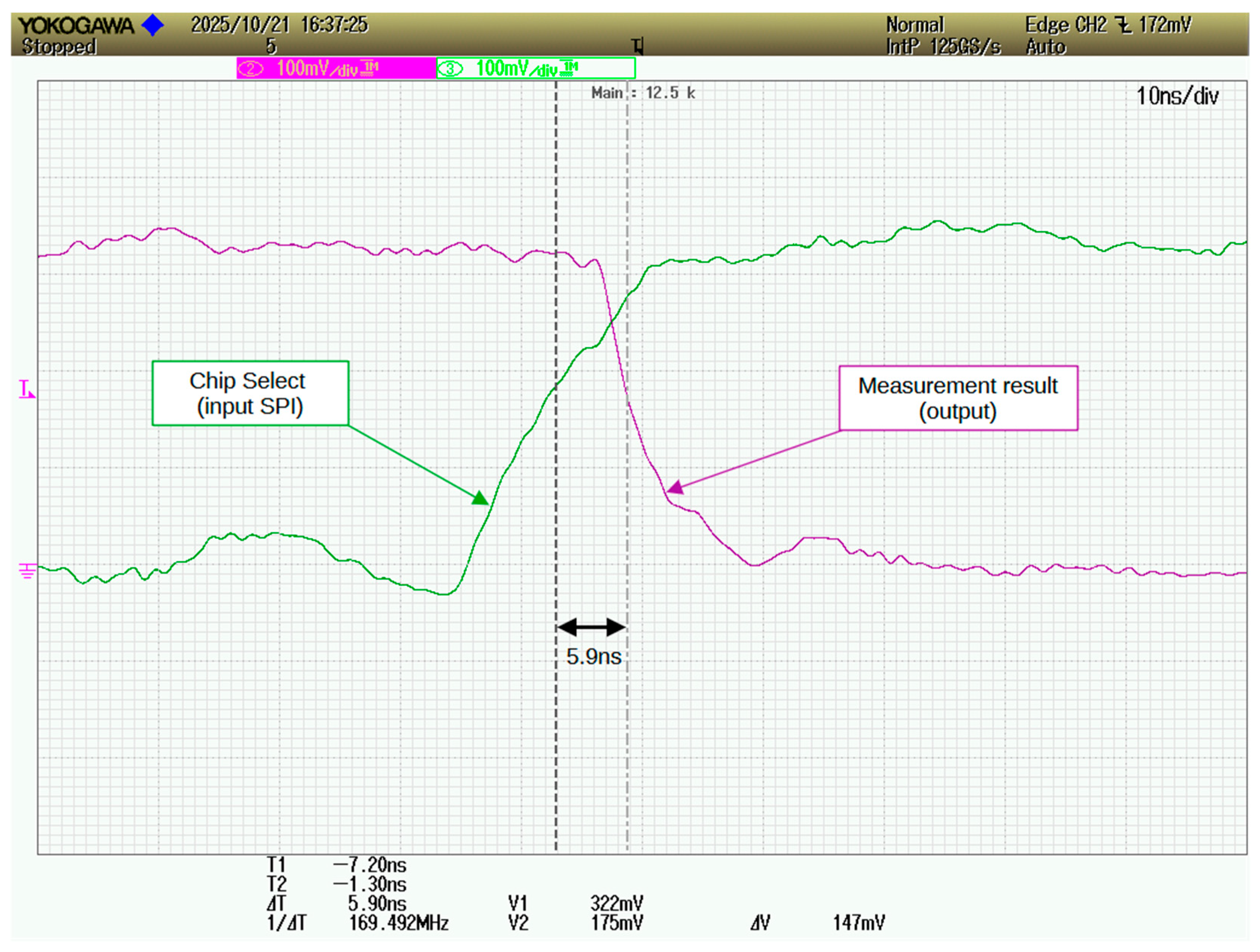
The total time from the start of processing to the delivery of the measured values to the controller corresponds to the SPI transmission time, as the values are written to output buffers immediately upon completion of the transfer. Synthesis results indicate an output signal delay of 8 ns relative to the end of the SPI transmission. Experimental measurements showed a delay of approximately 5.9 ns, as shown in
Figure 5. The maximum total time required to obtain a result, from the start of conversion to the end of transmission to the controller, is approximately 18 µs.
4.5. Voltage Measurement Module
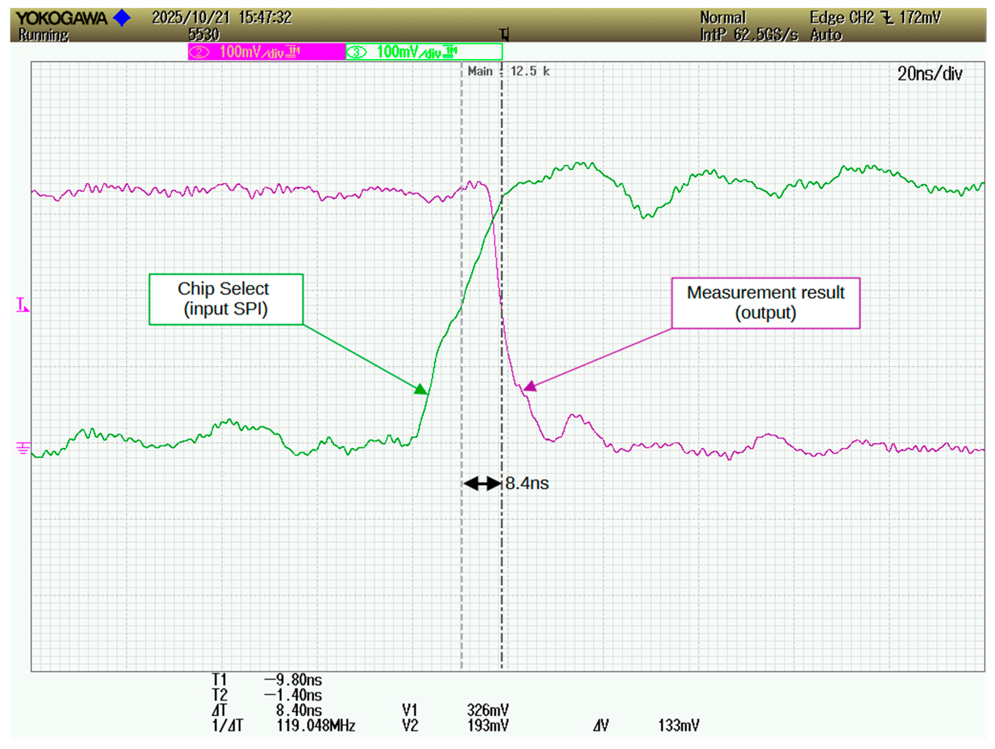
An LEM LV-25P Hall effect sensor was used to measure the capacitor voltage. The sensor’s output is digitized using a 12-bit ADCS7476 converter with an SPI interface. The measurement result, provided as a 16-bit value, is transmitted to a dedicated SPI interface in the FPGA at a clock frequency of 3 MHz. The 16-bit transmission cycle takes 5.3 µs. The delay of the voltage output signal on the 12-bit port relative to the end-of-transmission edge is shown in
Figure 6, where the measured delay is approximately 8.4 ns. The maximum measurement frequency of this converter is 10 MHz. Therefore, the maximum delay in this module is approximately 5.4 µs.
4.6. Capacitor Voltage Control Module
The capacitor voltage control module manages the charging and discharging processes of the C-dump capacitor. This module utilizes setpoints for the minimum and maximum voltage values at which capacitor charging is enabled or disabled. These voltages depend on the speed. At speeds below the rated speed, the capacitor voltage is maintained near zero. At high speeds, it assumes values consistent with those calculated in the simulation program. These voltage values are supplied from the regulator module.
4.7. Controller Module
The controller is implemented as a dual-mode discrete PID structure using specialized hardware logic. The controller inputs receive the speed setpoint from the user interface and the actual speed from the instantaneous speed measurement module. The output signal below the rated speed is the duty cycle of the PWM signal of the phase supply voltage. Within this range, the commutation angle values can also be changed according to predefined dependencies.
Once the rated voltage is reached, the speed is regulated by a second PID regulator that sets the commutation angles. In the case of the C-dump converter, the capacitor charge and discharge voltages are also varied within this range, allowing for a wider speed control range. The capacitor charge and discharge voltage values are determined based on predefined dependencies on the rotational speed.
By implementing the regulator elements as specialised hardware structures, the delays introduced by the regulator were significantly reduced. The delays introduced by the regulators, obtained during module synthesis are 1.2 µs. The regulator is clocked according to the instantaneous speed calculation period, so the delay in the regulator does not adversely affect the drive’s operation.
4.8. Output Decoder Module
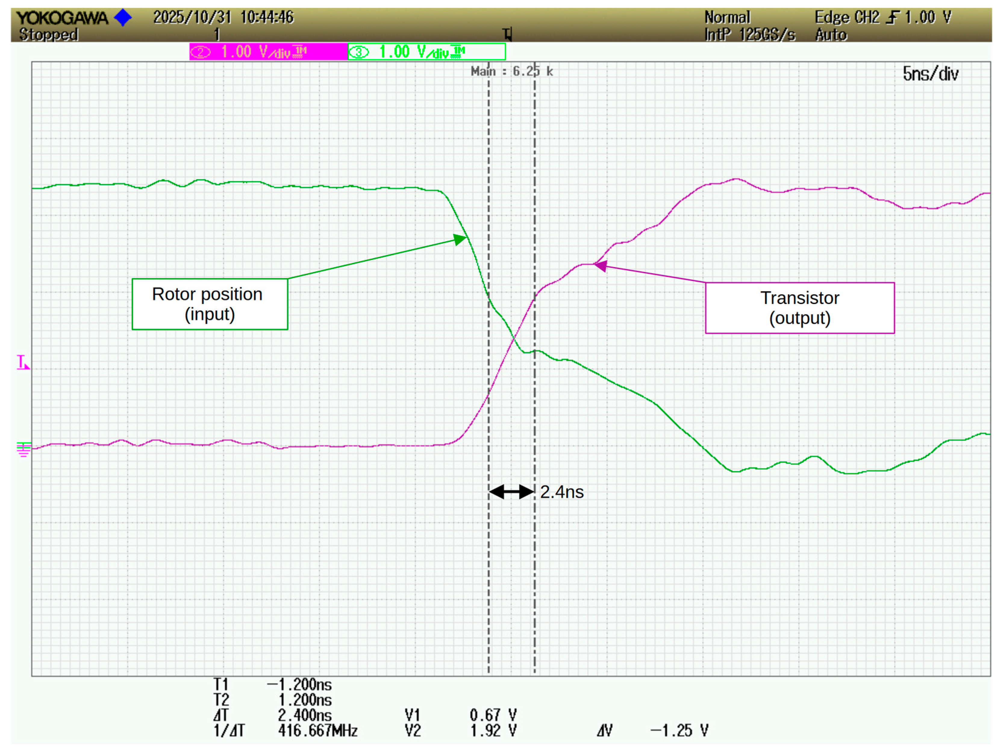
The output decoder module operates based on the instantaneous rotor angular position, the output signals from the PWM generator module, controlled by the output of the first controller, and the phase power supply angular ranges obtained from the output of the second controller. In the case of the C-dump converter, the minimum and maximum capacitor voltage values are also used. This module is designed as an asynchronous decoder. Depending on the input signals, it controls the operation of the drivers that switch the transistors powering the motor phases. Delays in this module result from the signal propagation time through the structure and are 2.0 ns, according to the module’s synthesis results. Measurement results for this module, after it was connected to the FPGA ports, are shown in
Figure 7. The measurements indicate a propagation delay of 2.4 ns.
4.9. Interface
The user interface consists of a serial menu module and a display control module. The display module comprises a configuration section, activated when the controller is powered on, which sets the operating mode, and a section that allows viewing of selected parameters during controller operation. The module displays current control parameter values, such as speed, phase currents, supply current, voltages, and commutation angles. It uses parameter values measured in the control path modules. To edit drive operating parameters, a four-button serial menu is provided, allowing functions to be selected and then edited. After configuring the parameters, two dedicated buttons are used to control the motor: one for starting and one for stopping the drive. This module has no direct impact on the controller’s operating speed because it operates fully concurrently.
4.10. Controller Synthesis
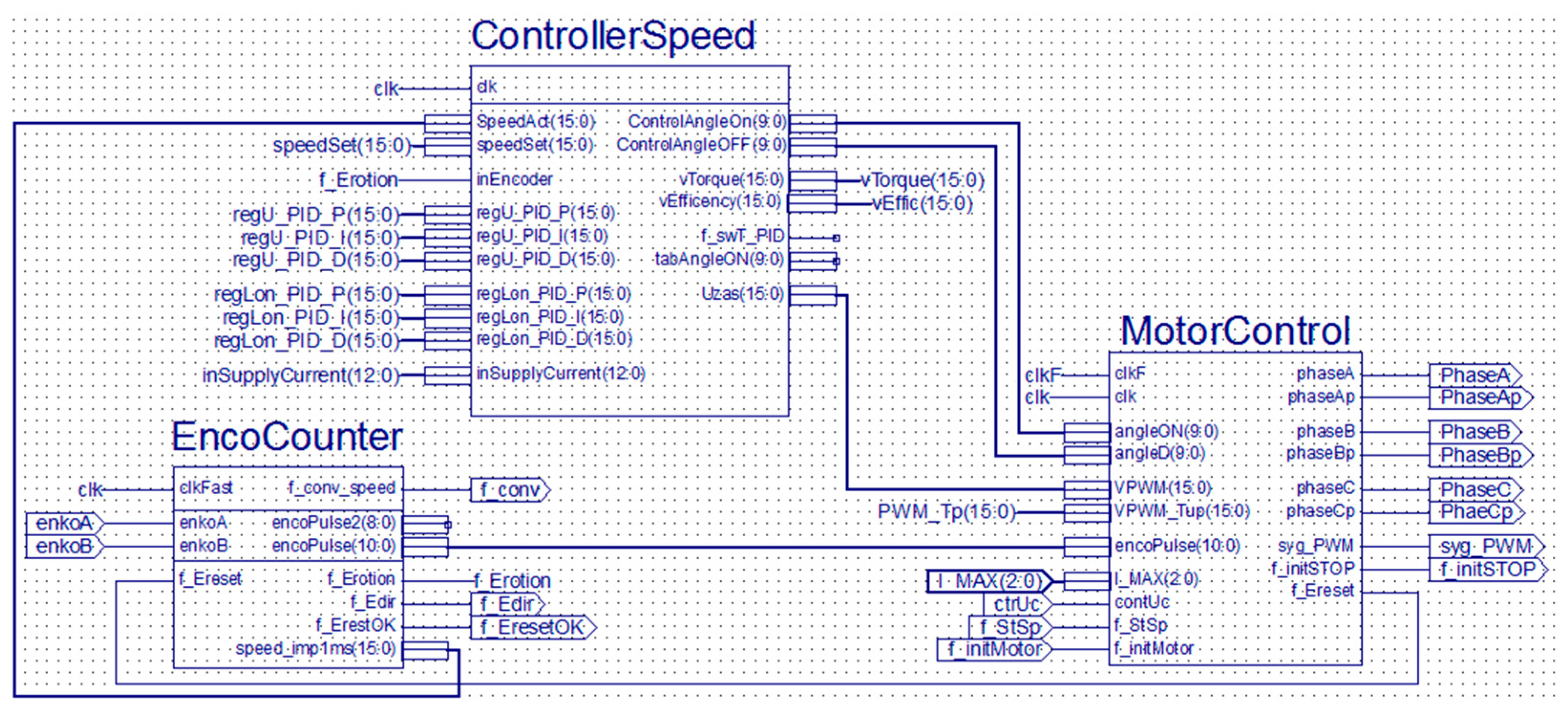
The controller was synthesised according to the block diagram shown in
Figure 8.
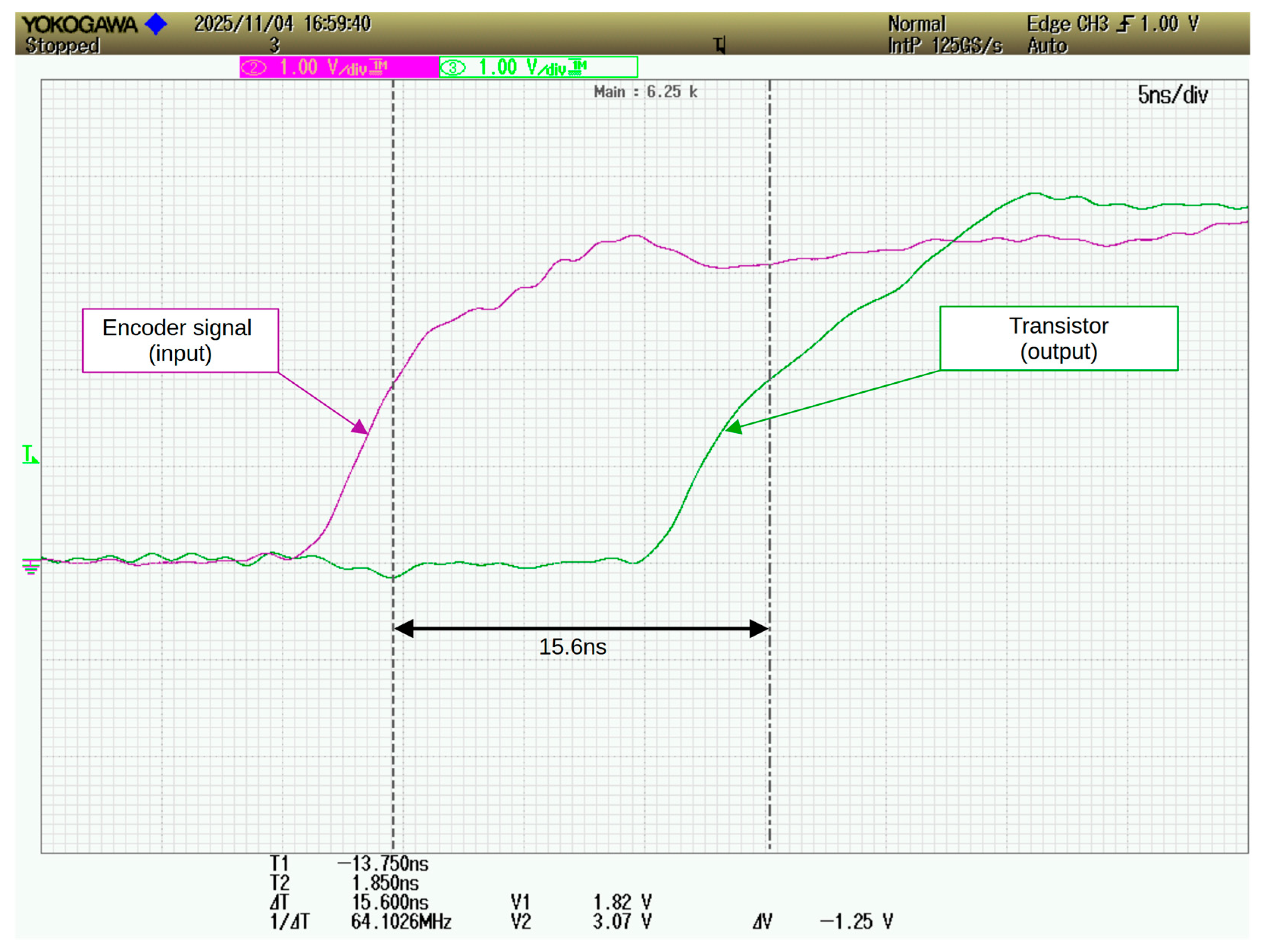
Functional modules were developed based on an analysis of the system’s operation. After testing the individual modules, the controller was synthesised. The most significant delays introduced by the control system originate from signal propagation paths between the encoder input and the outputs that controlling the phase supply transistors as the rotor angle changes. Another limitation is imposed by the PWM voltage period, which limits the controller’s operating speed.
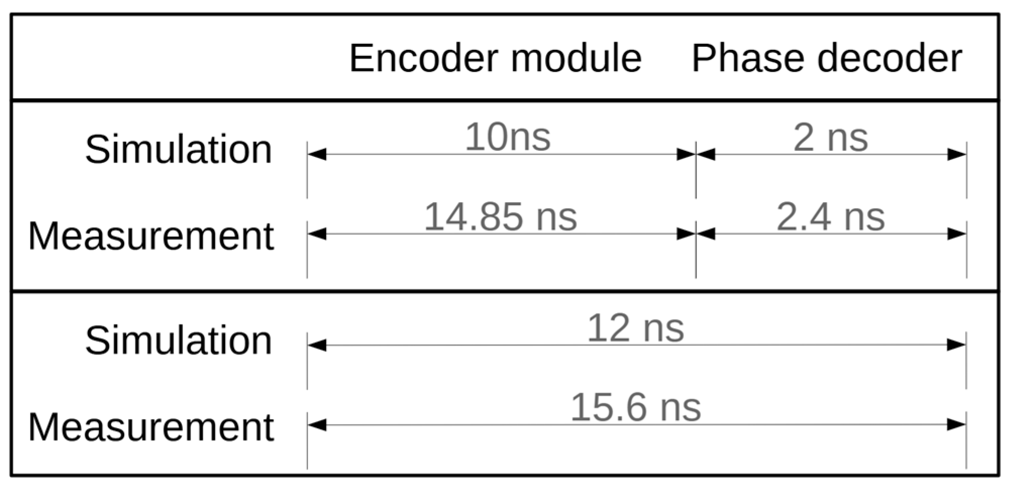
The maximum delay associated with signal propagation through the system from the encoder input to the outputs that control the motor phase power supply was determined during controller synthesis to be 15.6 ns. The measurement results of the output signal delays relative to the encoder signals are shown in
Figure 9. This represents the fundamental limitation on the maximum speed at which the controller can operate.
Since the encoder signal changes state 1440 times per rotor revolution, the minimum theoretical duration of a full revolution is 23 µs. Consequently, the controller can operate correctly, without reducing the angular position measurement resolution, at speeds of up to 2.5 million rpm. The maximum drive speed is primarily limited by the remaining drive components. Other modules, such as the PID controller, may operate at a lower update frequency.
The second critical element is the current limiting circuit. The total delay from the start of current measurement to PWM signal blocking is 45 µs. During this time, the current should not exceed the permissible value. Phase currents in high-speed motors increase rapidly due to the low inductance of the windings in these machines, as well as the increased supply voltage. Permissible delays in the current limiting circuit can only be determined for a specific motor and the power supply topology used. If the delays are excessive, it may be necessary to replace the current sensors.
Figure 10 presents the input and output propagation delays of individual controller modules as well as the delay of the critical signal path. The values were obtained from experimental measurements and synthesis results.
5. Peripheral Elements
The controller’s operation was tested in a drive with a maximum rotational speed of 12,000 rpm. Therefore, typical actuators, such as drivers and IGBT transistors, were used. According to the manufacturer’s specifications and the adopted algorithm and resolution of the rotor angular position measurement in the drive used for testing the developed controller, the maximum drive speed is significantly lower than the maximum controller speed. To increase the drive’s rotational speed, faster transistor drivers can be employed.
In the tested drive system, a C-dump converter was used. The circuit employs IRGP4640DPbF IGBT transistors, for which the maximum turn-on and turn-off times are 53 ns and 115 ns, respectively (at 25 °C). The transistors are driven by IR2104 gate drivers, characterised by maximum propagation delays of 160 ns for the rising edge and 150 ns for the falling edge, along with maximum rise and fall times of 100 ns and 50 ns, respectively. The total maximum switching delay of the transistors relative to the control signals at the FPGA outputs is therefore 263 ns for turn-on and 365 ns for turn-off. This delay can be considered constant and independent of the rotational speed.
The accuracy of determining commutation angles, current limiting, and other controller modules was verified for a drive with a 750 W three-phase SRM motor. For this motor, the angular range of the phase feed was assumed to be constant at 30 degrees. The relationship between commutation angles and rotational speed was determined using a simulation program in the Matlab Simulink (2024b) environment [
48].
The calculated dependencies of capacitor charging voltages and commutation angles were implemented in the controller as arrays, whose elements are interpolated using spline functions. The tests demonstrated the correct operation of the voltage regulator, current limiting circuit, capacitor charging circuit, and phase power supply angle range determination.
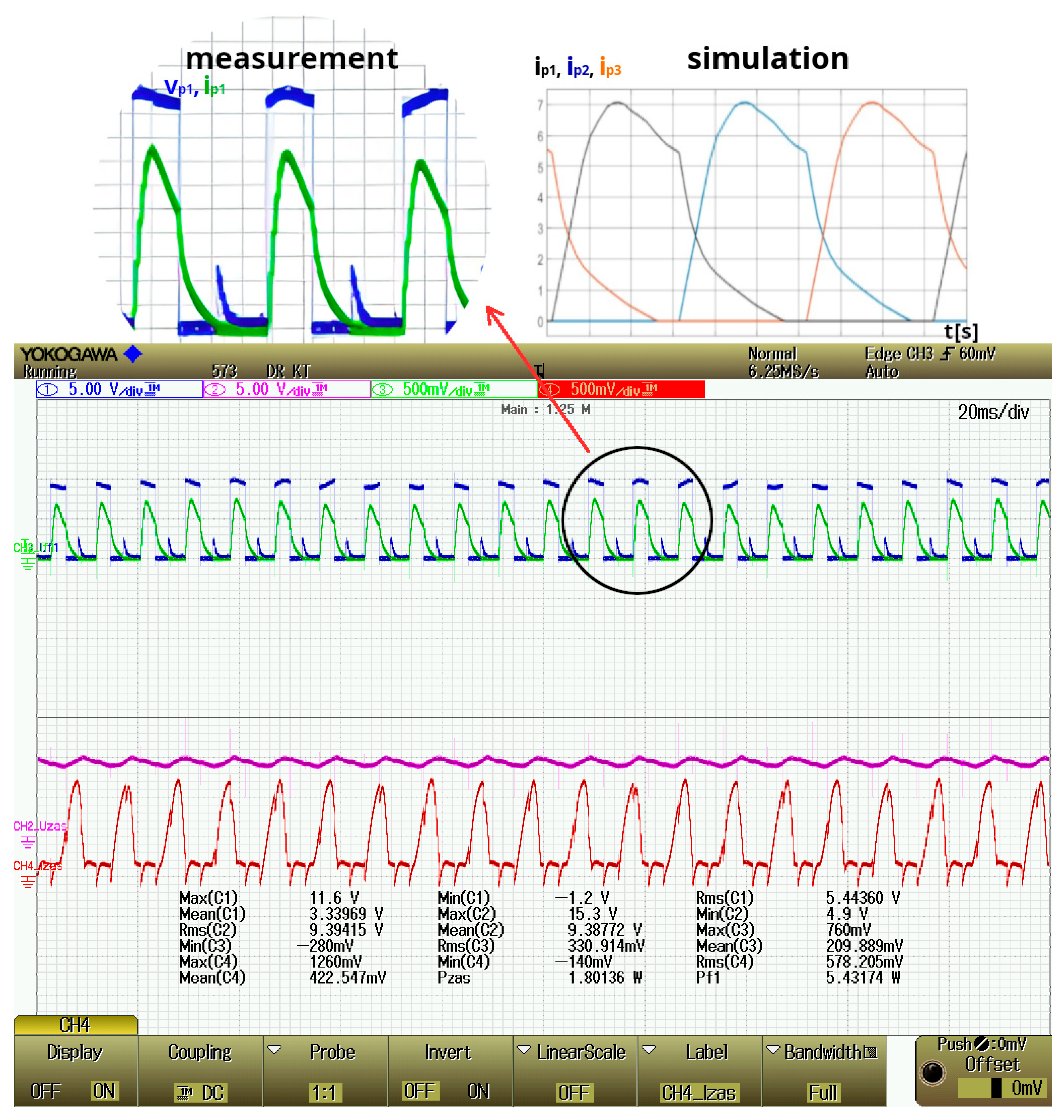
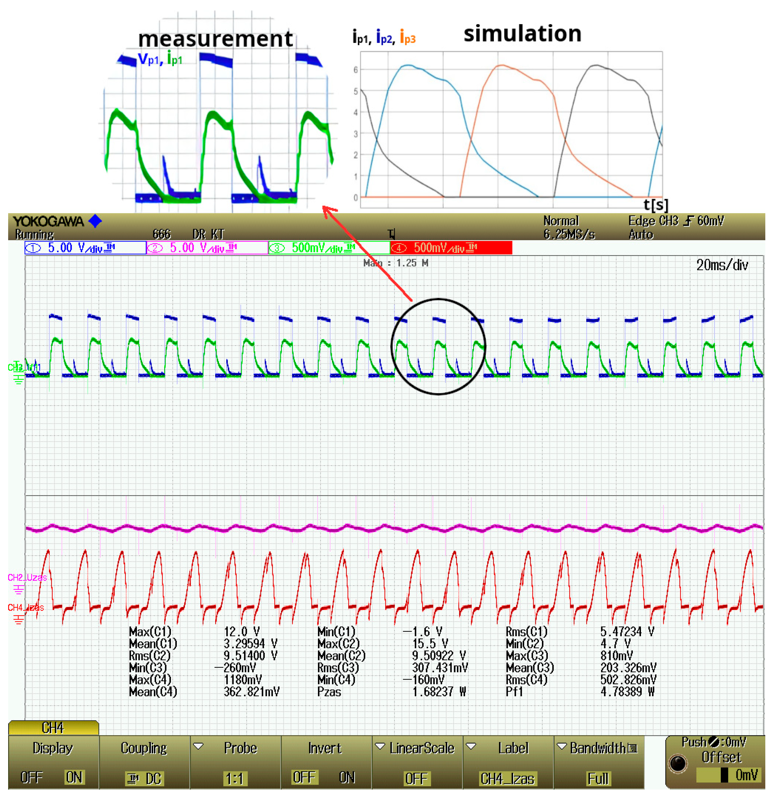
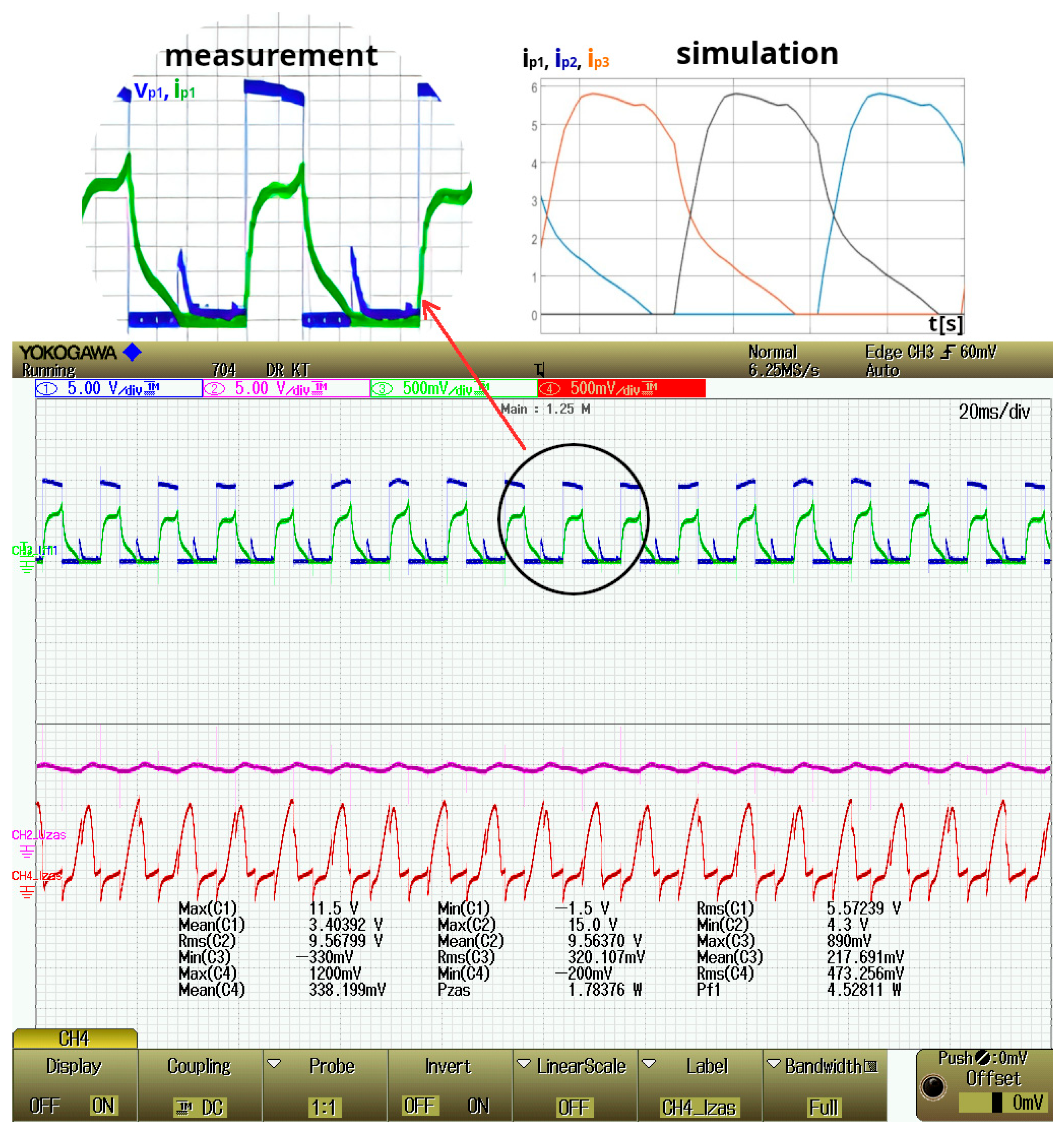
As part of the testing of the commutation angle controller, phase current waveforms were measured for various commutation angle values. The obtained results were compared with the drive simulation results and are presented in
Figure 11,
Figure 12 and
Figure 13. In all cases, similar current waveforms were obtained, characteristic of different phase power supply angle ranges.
Measurements and calculations were made with the supply voltage reduced to 130 V and a load of 2.5 Nm.
6. Summary
As part of the research, an SRM motor controller based on an FPGA programmable logic device was developed. The project was designed for a drive with a C-dump converter, but after adaptation the controller can be used with SRM drives employing various types of converters.
A controller for C-dump converters is more complex than those for typical SRM drive systems. Additionally, it must control the charging and discharging process of the C-dump capacitor. Similarly to the process of determining the control signals for the transistors powering the phase windings, the control of the capacitor charging and discharging process must be implemented with high priority. While the process of controlling the phase power supply based on encoder signals is clocked by the edges of these signals, the capacitor voltage measurement process must be performed continuously. This means that the measurement results must be analysed immediately after the measurement is completed. In a microcontroller-based system, this limits the maximum execution speed of the control algorithm. Thanks to the use of an FPGA, the implementation of this functionality has little impact on the maximum speed, as it is implemented fully concurrently.
As part of the research, a functional analysis of the control system was performed. The signal delays introduced by the functional modules essential for high-speed control were analysed. As a result, the maximum delay introduced by the programmable logic device-based controller was determined and verified experimentally, thus directly addressing the scientific objective of this study.
By developing the controller as a concurrent hardware structure instead of a microcontroller program, the maximum signal propagation time through the system was limited to 15.6 ns. Within this time, all functions necessary for proper drive operation are executed. The tests were performed using a Spartan 7 FPGA clocked at 100 MHz. These results confirm that the proposed control architecture does not impose significant dynamic limitations on high-speed SRM operation.
Other modules, such as the user interface or serial interface, do not affect the speed of the control algorithm because they operate concurrently. Further expansion of the controller also does not significantly affect its speed, as long as the execution time of new functionalities does not exceed the maximum propagation time of the control signals through the system, as additional modules can be implemented concurrently. For example, it is possible to change the regulator type, implement the mathematical model of the drive, etc., without affecting the speed control range.
The main factor limiting the controller’s maximum operating speed is the path for determining the phase power supply angle ranges, from the incremental encoder inputs to the transistor control outputs. This path also includes PWM voltage regulation, commutation angle regulation, phase current measurement, and the current limiting circuit, which, however, operate at a slower cycle. The achieved delay of 15.6 ns indicates that the controller can theoretically perform basic functions correctly at motor speeds up to 2.5 million rpm, meaning that the controller itself is not the speed-limiting factor. The measured total delay is smaller than the sum of the delays of the individual control path modules because it accounts for only a single connection between the control path and the FPGA output ports.
Nevertheless, when considering the transistor commutation times, in order to limit errors to the assumed rotor angular position resolution of 0.25 degrees, the maximum drive speed should be limited to 110 k rpm. For higher speeds, faster power electronic components may be required.
Additional functionality that significantly slows down microprocessor controllers, such as the measurement and analysis of the charge state of the C-dump capacitor, does not affect the maximum speed of the control algorithm implementation in the case of the FPGA controller.
If there are more complex calculations, the controller can be expanded with a microcontroller cooperating with the FPGA or the microcontroller can be implemented within the FPGA, to perform selected algorithm functions that are difficult to realise as hardware structures. The main advantage of the proposed FPGA-based solution remains the implementation of the control algorithm as specialised hardware modules operating concurrently.