


Abstract
Artificial intelligence (AI)-based digital integrated circuit (IC) design is exploding in the chip industry. Agent-based digital logic design is considered the next paradigm in computer architecture at the chip level. In this work, we explore the domain specialization of a Claude-based AI agent on the specific topic of Fast Fourier transform (FFT) algorithms, using butterfly architectures for sparse factorized matrix-vector realization of discrete Fourier transform (DFT) applied to the hardware realization of the novel special case of approximate DFT with corresponding sparse factorizations. Unlike FFTs, which are well-known and commonly described in the literature and public hardware description language (HDL) code bases, approximate discrete Fourier transforms (ADFTs) are a new approach to frequency computation in the discrete time domain that scales as arithmetic (multiplication) operations. HDL code implementation of these factorizations is not available in public repositories, and while the contents of the proprietary training corpus of Claude cannot be inspected, this absence makes it unlikely that the algorithm is represented in the training data. No retraining or fine-tuning of the model is done in this work; instead, we specialize a general-purpose AI agent through prompting at design time using our published ADFT matrices and their sparse factorizations. The agent combines this provisioned domain knowledge with its existing knowledge of FFT theory, including Cooley–Tukey butterfly networks, to adapt standard FFT algorithms for the ADFT use case as the number of frequency points N scales to large values. We verify mathematical performance as well as digital logic correctness as the AI agent scaled design complexity starting from small values of N to larger values, progressively, in a controlled and systematic way. Finally, the agent-generated HDL source code is synthesized as reusable intellectual property (IP) blocks across both an AMD Xilinx Zynq UltraScale+ radio-frequency system-on-chip (RF-SoC) (ZCU216 evaluation platform) and 28 nm TSMC application-specific integrated circuit (ASIC) process design kit (PDK). The results demonstrate that a single AI-generated design description successfully re-targets multiple physical implementation flows, validating the feasibility of automated AI agents for specialized electronic design automation (EDA) workflows.
Keywords:
digital IC design; FFT; ADFT; Cooley–Tukey algorithm; FPGA; ASIC; RTL; AMD Xilinx Zynq UltraScale+ RF-SoC; TSMC 28 nm PDK; EDA 1. Introduction
Artificial intelligence (AI)-assisted digital integrated circuit (IC) design is rapidly transforming the semiconductor industry, ranging from large language model (LLM)-based generation of register-transfer-level (RTL) code from natural-language design specifications [1,2,3] to fully autonomous agentic AI systems that plan and execute electronic design automation (EDA) tools across the entire RTL-to-GDS-II (RTL2GDS) flow [4,5] which has been reviewed in recent surveys [6,7]. Collectively, these techniques extend the assistance of AI across every stage of chip realization, from field-programmable gate array (FPGA) prototyping to application-specific integrated circuit (ASIC) tape-out. Although recent studies have demonstrated the capabilities of agentic AI in RTL generation, their performance is evaluated on LLM-based RTL generation for well-known circuits such as adders, first-in, first-out (FIFO) buffers, and fast Fourier transform (FFT) butterflies, which are abundantly represented in published papers, textbooks, and open-source Verilog repositories [8,9]. Whether an agent can correctly implement novel algorithmic content remains an open question.
This paper investigates that question using the ADFT as the test algorithm. The approximate discrete Fourier transform (ADFT) [10,11] computes the discrete Fourier transform (DFT) through sparse matrix factorizations whose entries are restricted to trivial multipliers, such as , enabling multiplierless butterfly-style hardware implementations whose arithmetic complexity scales as . These factorizations are documented only in the authors’ own publications, and no hardware description language (HDL) implementation of them exists in any public repository. Therefore, no reference design is available to retrieve and adapt, so the RTL must be generated by the AI agent from the matrices. In contrast, the classical FFT and the Cooley–Tukey decomposition are extensively documented and well-represented in general-purpose LLM training data. Generating correct ADFT hardware therefore requires a general-purpose LLM to perform a qualitatively more demanding task than benchmark RTL generation where it must take the provided factorization matrices as ground truth, and integrate them with its general knowledge of FFT theory, index mappings, twiddle factors and Cooley–Tukey butterfly networks.
Organization of the Paper
The remainder of this paper is structured as follows. Section 2 reviews related work in language-model-based RTL generation, agentic AI in EDA, and ADFT and multiplierless hardware. Section 3 describes the domain specialization of the Claude-based AI agent and the progressive design methodology, in which each verified transform length becomes a building block for higher-order architectures. Section 4 presents the Cooley–Tukey composition of the provided factorizations and the resulting family of RTL architectures for to 16,384, including the fixed-point formats and pipeline organization. Section 5 details the bit-exact verification methodology linking matrix-form MATLAB golden models to streaming self-checking testbenches. Section 6 reports radio-frequency system-on-chip (RF-SoC) and 28 nm complementary metal-oxide-semiconductor (CMOS) synthesis results for the agent-generated designs, demonstrating the synthesizability of the generated Verilog for both FPGA and ASIC targets. Finally, Section 7 discusses the findings and directions for future research.
2. Review
2.1. Language-Model-Based RTL Generation
The application of LLMs to generate HDL codes began with direct translation of natural-language specifications into synthesizable code, which has been surveyed in several instances [6,7,12]. A critical review classifies thirty-one such published efforts by their use of fine-tuning, reinforcement learning, retrieval-augmented prompting and multi-agent orchestration, across eight methodological dimensions that include debugging support, post-RTL metrics and benchmark development [13]. More recent work treats synthesizability of the generated code as an explicit objective [14,15] and documents systematic quality failures in HDL question answering [16].
From the beginning, this domain has developed along three primary directions; fine-tuning open models on hardware specific datasets, adapting general-purpose models to the hardware domain, and constructing benchmarks to measure the performance of those models. Early work showed that general LLM models could produce syntactically correct Verilog for small, well-specified digital modules [1]. Subsequent work fine-tuned open-source models extensively on Verilog datasets, showing that a relatively compact, domain-specialized model could approach or even exceed the functional correctness rates of much larger foundation models on similar tasks [2,3]. The same review [13] evaluates frontier commercial and open-weight models, among them Claude Sonnet 4 from the model family used in this work, on the VerilogEvalV2 and RTLLM-v2.0 benchmarks under both single-shot generation and generation augmented by a lightweight reflection loop. With the reflection loop, pass rates of up to 89.74% and 96.08% respectively are reported, matching or exceeding fine-tuned domain-specific pipelines without any retraining [13,17].
Adapting large foundation models to industrial chip-design, using continued pretraining in internal design data together with the retrieval of proprietary documentation, has been reported to improve performance across code generation, answering technical questions, and bug triage [18]. Moreover, conversational co-design has also been demonstrated end to end, with a language model participating in the design of a microprocessor subsequently fabricated in silicon [19].
Measurement of these generative capabilities is based on a small number of public benchmarks. These frameworks provide natural-language problem statements paired with reference implementations and testbenches, and score models based on functional equivalence rather than textual similarity [8,9]. However, the tasks used to evaluate those benchmarks are drawn almost exclusively from standard digital building blocks such as counters, finite-state machines, basic arithmetic units, FIFO memories, and single-stage FFT butterflies, all of which are heavily represented across academic textbooks and open-source repositories. Revised evaluations of the established benchmarks further demonstrate that HDLs constitute a small fraction of training data on which these models are trained, relative to other general software code [20], and the problems that are used in benchmark evaluation are already appearing in the training data, so a high score can reflect recall rather than generation, which is called contamination, and has been identified as a confound in benchmark interpretation [21]. Therefore, the prior work does not clearly show how a model performs in the absence of the required code in its training data, and this fundamental limitation serves as the point of interest for the present study.
2.2. Agentic AI in Electronic Design Automation
Beyond single-shot code generation, recent research focuses on autonomous AI agents that can invoke external tools and act on their results [22,23,24]. For instance, agent frameworks have been demonstrated to successfully translate natural-language instructions into EDA tool scripts to drive an entire RTL-to-GDS-II flow autonomously, planning the sequence of steps and interpreting tool outputs [4,25]. Instead of needing a perfect code on the very first attempt, these frameworks repair generated hardware descriptions iteratively in response to compilation and simulation errors [5]. Language models have similarly been applied to the verification side of the ASIC flow in generating assertions, testbenches, and stimulus for design validation [6].
Instead of a single agent involved, multi-agent engines extend this by dividing RTL generation among generation, simulation-scoring and debugging roles, reporting substantial gains over single-agent baselines [26]. Later systems add adaptive orchestration and hierarchical decomposition of a specification into dependency-ordered sub-modules, which succeeds on a system-scale design where monolithic generation fails entirely [27,28,29]. Moving further from RTL generation, a smaller number of efforts optimize power, performance and area (PPA) jointly with functional correctness, in one case through an evolving memory of optimization experience that improves strategy without retraining [30,31,32,33]. Also, the evaluation frameworks now score based on synthesizability and post-synthesis metrics along with the functional correctness [21]. Therefore, the contribution of language models is currently expanding from the writing of HDL code towards the ASIC design flow as a whole.
2.3. Approximate Discrete Transforms and Multiplierless Hardware
Approximate discrete transforms replace the exact transform matrix with a matrix whose entries are restricted to trivial multipliers, such as [10]. Under this constraint, every matrix-vector multiplication reduces to a trivial sign inversion or a power-of-two bit shift, enabling the complete transform to be realized in hardware entirely without traditional multipliers.
Such approximation approach resulted in a number of multiplierless DFT approximations [10]. They have found application in multi-beam RF apertures and has since been realized across a range of platforms, an 8-point digital array receiver at 2.4 GHz, a 16-point FPGA-based receiver reporting a 70% hardware reduction relative to an exact FFT, a 32-beam digital subsystem at 5.8 GHz [34], and analog CMOS multi-beamformers in 65 nm and 180 nm processes [35]. More recently, the same factorizations have expanded beyond beamforming applications, replacing the FFT in Fourier neural operators for partial differential equation (PDE) solving [36].
The underlying factorization matrices, their hierarchical Cooley–Tukey composition, and their flexible hardware pipelines appear in the literature; but no corresponding HDL source implementation exists in any public repository. Therefore, no RTL is present for a general-purpose LLM to retrieve, and the hardware has to be constructed from the matrices themselves, making it a suitable test case to evaluate the true generative capability of AI agents.
3. Domain Specialization of the Claude Agent and Design Methodology
In this section, we present how a general-purpose LLM is transformed into an effective RTL generator for which no public HDL implementation exists. The proposed methodology relies on two key principles. The first is design-time specialization; the published ADFT sparse factorization matrices are provided to the agent as algorithmic ground truth. The agent then combines this explicit domain knowledge with its general knowledge of FFT theory, including index mappings, twiddle-factor operations, Cooley–Tukey decompositions, and butterfly structures, to construct RTL architectures for transform lengths substantially larger than the available ADFT building blocks. Second is the separation between design generation and functional verification. The agent autonomously generates the SystemVerilog RTL DUTs and their self-checking testbenches, but the final authority over functional correctness remains with the human RTL designer, who implements independent matrix-based MATLAB (R2021b) golden reference models and uses them for bit-exact verification, as described in Section 5.
3.1. Agent Configuration and Tool Environment
The AI agent employed in this work is built on Claude (Anthropic), a general-purpose large language model operated in an agentic configuration. No retraining, fine-tuning, or modification of the underlying model is performed at any point of this work; the model’s weights remain those of the publicly available general-purpose LLM, and all domain specialization described in Section 3.2 is applied at design time through the information provided to the agent via prompts. All the instructions to the agent were given through the natural-language prompts where they were organized in a way that it starts from the lower level of the design hierarchy and proceed to higher levels.
3.1.1. Single-Shot Generation Without the Factorization
As a control experiment to evaluate the performance of single-shot generation, the agent was asked to generate a 32-point ADFT core without being supplied the factorization matrices, using only the basic prompt “Generate the RTL for 32-point ADFT using sparse factorization matrices for hardware implementation”. The agent did not reproduce the expected transform and instead it generated a radix-2 decimation-in-time structure of five sparse butterfly stages. It reported that the design was pipelined and free of multipliers, that it is verified against a Python (https://www.python.org, accessed on 18 September 2026) reference model the agent had written with 2000 test vectors, and that it synthesized in Yosys with no multipliers inferred. The full transcript of this session is available at the link given in the Data Availability Statement. This clearly establishes the need for the human–agent interaction and design iteration described in the following subsection.
3.1.2. Human–Agent Interaction and Design Iteration
The interaction between the designer and the AI agent evolved throughout the design process as the implementation knowledge accumulated. The initial ADFT architectures required detailed prompts that explicitly specified the sparse factorization matrices, matrix representation conventions, fixed-point arithmetic discipline, pipelined datapath organization, and module interface requirements. These early interactions established the implementation conventions that guided all subsequent hardware generation.
The first prompt provided to the AI agent requested the generation of a pipelined signed adder/subtractor with parameterized word length and fixed pipeline latency.
Prompt 1.
Generate SystemVerilog code for a parameterized signed adder/subtractor module. The input operands should be signed and parameterized, and the output should be one bit wider than the inputs to avoid signed overflow. The design shall be fully pipelined with an internal latency of four clock cycles from input to output.
The AI-generated RTL module is shown in Listing 1.
Prompt 2.
Generate SystemVerilog code for a parameterized delay module. The module should delay the input signal by a configurable number of clock cycles. The data width and delay length should be parameterized. The design shall operate synchronously with the clock and include an active-low reset that initializes all pipeline registers. The implementation shall be fully synthesizable and suitable for reuse in larger pipelined RTL designs.
| Listing 1: AI-generated four-stage pipelined signed adder/subtractor. |
 |
The AI-generated RTL module is shown in Listing 2.
In the subsequent prompts the level of abstraction was increased by requesting the implementation of the 8-point ADFT core from its sparse factorization matrices provided in the same prompt while explicitly mentioning to reuse the adder and the delay modules already generated. This progression concluded in the generation of the four largest architectures 2048-, 4096-, 8192-, and 16,384-point ADFT from a single prompt requesting their implementation using the previously developed 8-, 16-, and 32-point sparse-factorized ADFT cores together with the Cooley–Tukey decomposition. Table 1 presents representative prompts at three points in this sequence.
Table 1.
Representative prompts at three points in the design sequence, showing the contraction from full specification to single-sentence directive as context accumulated.
| Listing 2: AI-generated delay module. |
 |
This evolution demonstrates that the designer’s primary role was to establish the architectural intent and implementation conventions during the early stages of development, while the AI agent subsequently propagated these conventions across the remaining transform hierarchy. As a result, prompt complexity decreased significantly as the transform size increased, enabling efficient generation of increasingly complex RTL designs with only minimal additional designer intervention.
3.2. ADFT Sparse Factorization Matrices
An approximate discrete Fourier transform (ADFT) is an integer matrix defined over a set of trivial multipliers, such as , capable of retaining sought mathematical properties of the exact DFT matrix .
This representation eliminates the need for multipliers and enables hardware implementations with lower power consumption, reduced silicon area, and higher operating speed than conventional FFT-based realizations. The sparse factorization matrices employed in this work, which are available in the literature, further decompose the approximate transform matrix into a sequence of sparse matrix operations that are well-suited for efficient RTL implementation.
Matrices as Ground Truth
The domain knowledge supplied to the agent consists of the complete factor matrices of the two base transforms, given entry by entry. The selected 8-point approximate DFT was originally introduced with fast algorithms provided in [10] and associate digital architectures introduced in [35]. The mathematical formulation is given by the following:
applied right-to-left to the input vector, with
and the output permutation
The adopted 16-point approximate DFT is the one suggested in [10] equipped with fast algorithms developed in [10] and digital architecture detailed in [35]. This approximation is furnished by the following factorization:
with the diagonal stage
and the sparse factors
In terms of the 32-point approximate DFT , we selected the method introduced [10] (, ) whose fast algorithm is described in [11]. Due to the very large size of the matrices, we refer the readers to [11] for the explicit numerical form of its factor terms and its complexity analysis.
3.3. Adaptation of General FFT Principles to the ADFT Architectures
The sparse ADFT factorization matrices were explicitly provided to the agent, whereas the Cooley–Tukey decomposition was assumed to be part of its pretrained knowledge. To validate this assumption before introducing implementation-specific guidance, the agent was prompted to explain the Cooley–Tukey algorithm and its underlying mathematical principles. Because the Cooley–Tukey algorithm specifies only how transform stages are composed and places no constraint on the kernel itself, the supplied 8-, 16-, and 32-point ADFT cores can directly substitute for conventional discrete Fourier transform (DFT) kernels at each stage. The agent could therefore combine general FFT knowledge that it already possessed with the provisioned ADFT matrices to construct larger approximate transforms, and the resulting decomposition is presented in Section 4.
3.4. Fixed-Point Arithmetic and Bit-Exact Design
The acceptance criterion for every generated design is a bitwise comparison with the reference model with zero tolerance. Bitwise comparison against a reference model is only meaningful if both perform identical arithmetic. Therefore a fixed-point discipline was established and the agent was instructed to follow it throughout RTL generation.
In synthesizable RTL, a port declared logic signed [15:0] carries a 16-bit integer. The Q2.14 interpretation where the stored integer represents a value scaled by is a convention maintained by the hardware and the reference model, so both operate in the same integer domain. Each input value v is converted to an integer code before providing the stimulus to the testbench or the reference model, and no bits are discarded thereafter, and rather than quantizing between stages to hold a fixed word length, each core widens its word length monotonically to support bit growth.
Even though the reference model runs in double precision arithmetic, it operates only on these integer codes. Since double precision represents every integer exactly up to , it acts as an exact integer calculator over the word lengths used here, and therefore, any mismatch between the RTL and the matlab reference model indicates an implementation error associated with the AI-generated RTL code.
4. Cooley–Tukey Decomposition of the Generated ADFT Architectures
The agent generated RTL for the N-point ADFT cores with directly from the provided sparse factorizations. Longer transforms, from to , are obtained by the Cooley–Tukey decomposition which expresses a transform of composite length as two ranks of shorter transforms, each realized by one of these verified cores. This section describes the decomposition and shows how it is applied to generate the higher-order ADFT architectures.
4.1. Two-Rank DIT Decomposition and Index Mappings
Every generated design of length instantiates the architecture shown in Figure 1, a Cooley–Tukey structure with a two-rank decimation-in-time decomposition, . Here, rank denotes one of the two layers of complete base-transform blocks, as distinct from a stage, which is one factor matrix inside a single core.
Figure 1.
Two-rank decimation-in-time Cooley–Tukey architecture used for all generated designs of length .
The input frame is mapped onto an grid by
Rank 1 applies parallel copies of the inner base transform along , the twiddle stage multiplies each grid point by , and rank 2 applies parallel copies of the outer transform along , as shown in Figure 1. The results are read out under the output index map,
The template is fully parallel and fully pipelined, where all N samples enter on the same clock, every stage is registered, and one complete frame is accepted per clock at fixed latency. Each rank is a set of identical cores that operate simultaneously.
For an example, consider factored as , so that and . Rank 1 then holds sixteen parallel 8-point ADFT cores and rank 2 holds eight parallel 16-point ADFT cores. By Equation (13), each rank-1 core takes every sixteenth input sample, i.e., the first receives , the second , and so on, thereby providing eight samples to each 8-point ADFT core. After the twiddle stage, by Equation (14), each rank-2 core produces every eighth output bin, i.e., the first gives , the second , and so on, producing sixteen output bins from each 16-point ADFT core.
4.2. Quantized Twiddle-Factor Implementation
The twiddle stage forms the interface between the two ranks and is the only part of the generated architectures that performs true multiplication, as the ADFT base transforms only consist of additions, subtractions, sign inversions, bit shifts, and permutations. At each of the N decomposition points, the intermediate output is multiplied by
implemented by the pipelined twiddle_cmult module. Because the twiddle factors are fixed for a given transform length, these are constant-coefficients rather than general multipliers, and the multiplier resources scale linearly with N. These are written as ordinary multiplications in the RTL rather than as hand-coded shift-and-add networks or in canonical signed digit form, and because each coefficient is a parameter of the module twiddle_cmult, optimization is left to the synthesis tool, which removes the trivial coefficients and leaves non-trivial multipliers. The multiplication products are kept at full width, input 14 fractional bits, and output 28 fractional bits, with no rounding or truncation, and therefore no error is introduced in this stage. The only error is in the coefficients when arranging them in the Q2.14 format.
4.3. Generated RTL Architectures and Their Implementation Characteristics
The decomposition described above is used to generate composite architectures listed in Table 2. Up to , both ranks are populated directly by the provisioned base cores , and . Beyond that, for the inner rank is itself a Cooley–Tukey composite generated earlier in the sequence, while the outer rank remains 32 instances of . The 16,384-point design is therefore built from the 512-point design, which is built from and , so that each verified architecture becomes a building block for the next.
Table 2.
The generated approximate discrete Fourier transform (ADFT) architectures, .
5. Verification Methodology and Results
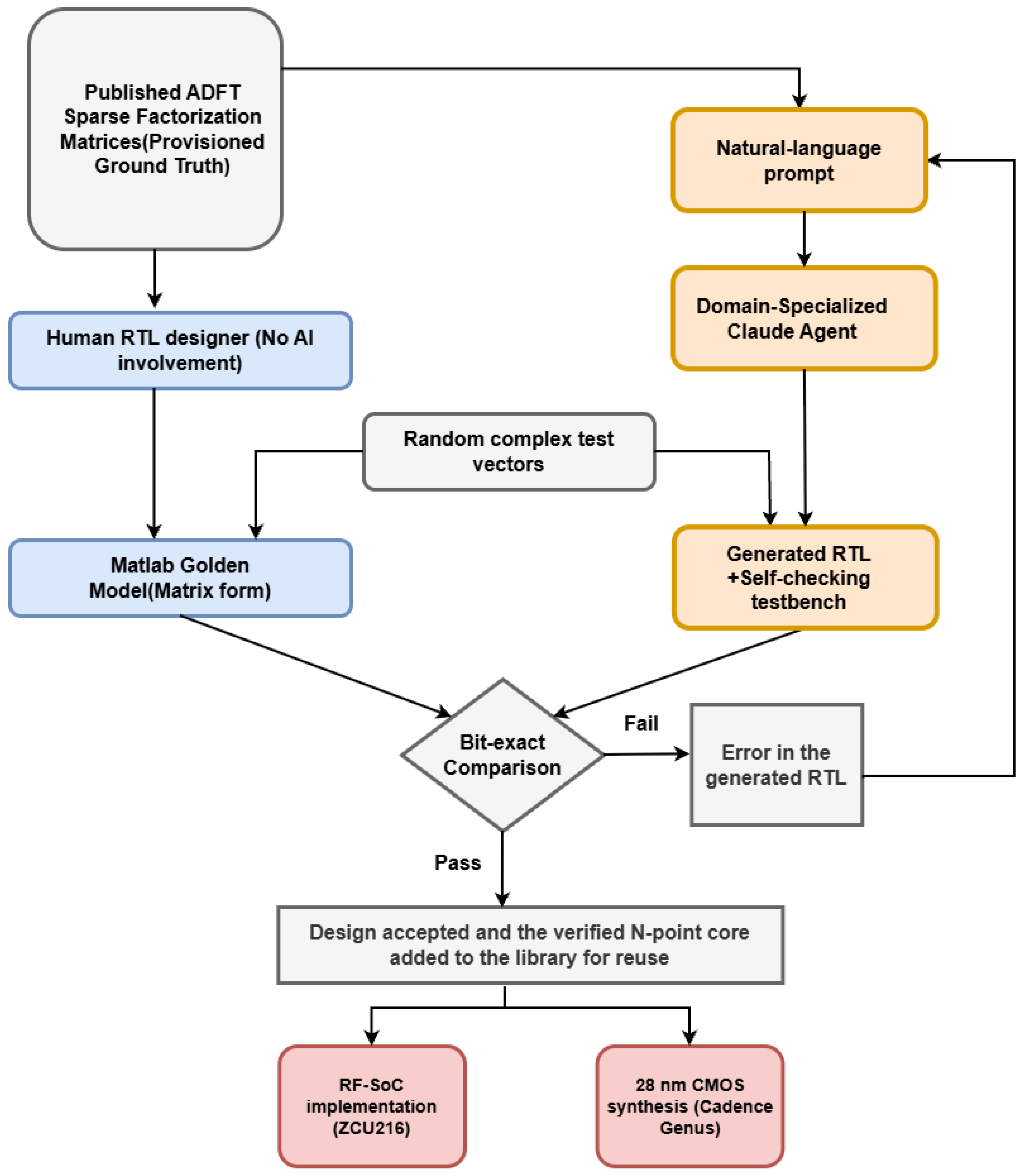
Each generated RTL design is validated by bit-exact comparison against a MATLAB reference model and accepted only if its outputs match the reference bit-for-bit across the full test set, with zero tolerance, rather than by relying on the agent’s assessment of its own output. The reference is written by the RTL designer with no AI involvement and is derived directly from the provisioned factorization matrices in matlab, so it serves an external, executable passing criterion that the generated RTL should meet.
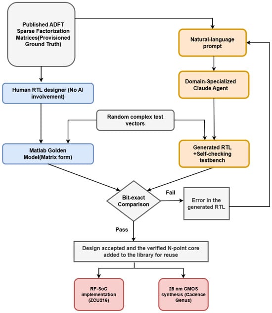
The bit-exact verification flow used in this work is shown in Figure 2. The complex random test vectors are quantized once to Q2.14 integer codes under the discipline of Section 3.4 and supplied simultaneously to the RTL testbench and to the MATLAB reference model. During comparison, an exact match confirms that the agent translated the factorization and its Cooley–Tukey composition into synthesizable logic correctly, whereas any mismatch brings out an implementation error with the AI-generated RTL.
Figure 2.
Flowchart of the proposed methodology and the bit-exact verification. The sparse factorization matrices are provisioned along two independent paths, to the Claude agent, which generates the register-transfer-level (RTL) and testbench, and to the human designer, who writes the MATLAB golden model with no artificial intelligence (AI) involvement. The same test vectors drive both, and a design is accepted only on an exact match and a mismatch is fed back to the agent.
5.1. Matrix-Form MATLAB Golden Models and Vector Generation
The Matlab golden reference model evaluates each transform as a sequence of matrix-vector products. For a base transform, the factor matrices are applied in order, , with each product computed on integer codes. For a composite transform, the two ranks and the twiddle stage are applied under the index maps of Equations (13) and (14). Each ADFT core is exercised with test vectors which are uniformly distributed random complex samples spanning the full Q2.14 input range.
5.2. Streaming Self-Checking Testbenches and the Bit-Exact Comparison
Each design is validated in the Xilinx Vivado 2020.2 simulator by a self-checking testbench generated by the Claude agent that streams one complete frame per clock. The input stimulus and the expected outputs are both produced by the MATLAB reference model and supplied to the testbench as text files, which the testbench reads at run time. As the stimulus is applied continuously rather than frame by frame, the design is verified under the back-to-back throughput; thereby, any pipeline hazards such as data leakage across pipeline stages or mismatch in pipeline delays are exposed as errors. Before comparison, the testbench compensates for the fixed pipeline latency of the design, aligning each output frame with the input frame that produced it. Each real and imaginary output code is then compared directly with the corresponding reference value read from the expected-output file. For any mismatch, the testbench reports the input frame index, the output frame index and both values, and every run terminates with an explicit pass or fail status.
5.3. Verification Results Across All Lengths
All 12 transform lengths passed with zero mismatches over 100,000 frames each, covering both the provisioned base cores and the nine composite architectures built from them.
For composite ADFT cores (), each base transform is verified before being reused as a building block in the next hierarchical stage. Therefore, any output mismatch at length N must originate from the newly introduced intermediate stages, namely, index mapping and twiddle-factor multiplication, rather than from a previously validated base-transform core. Consequently, functional errors are localized directly to the incremental operations performed, thereby eliminating the need to search the entire architecture during debugging.
6. RF-SoC, and 28 nm CMOS Synthesis Results
6.1. RF-SoC Implementation Results
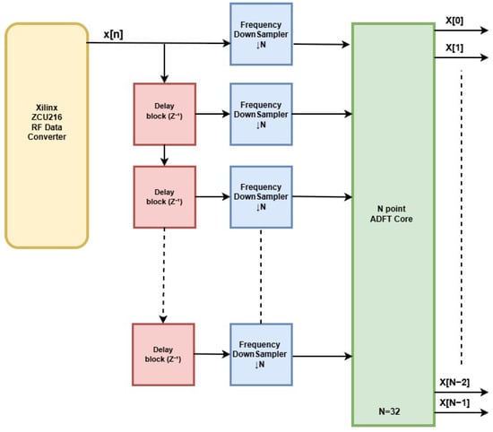
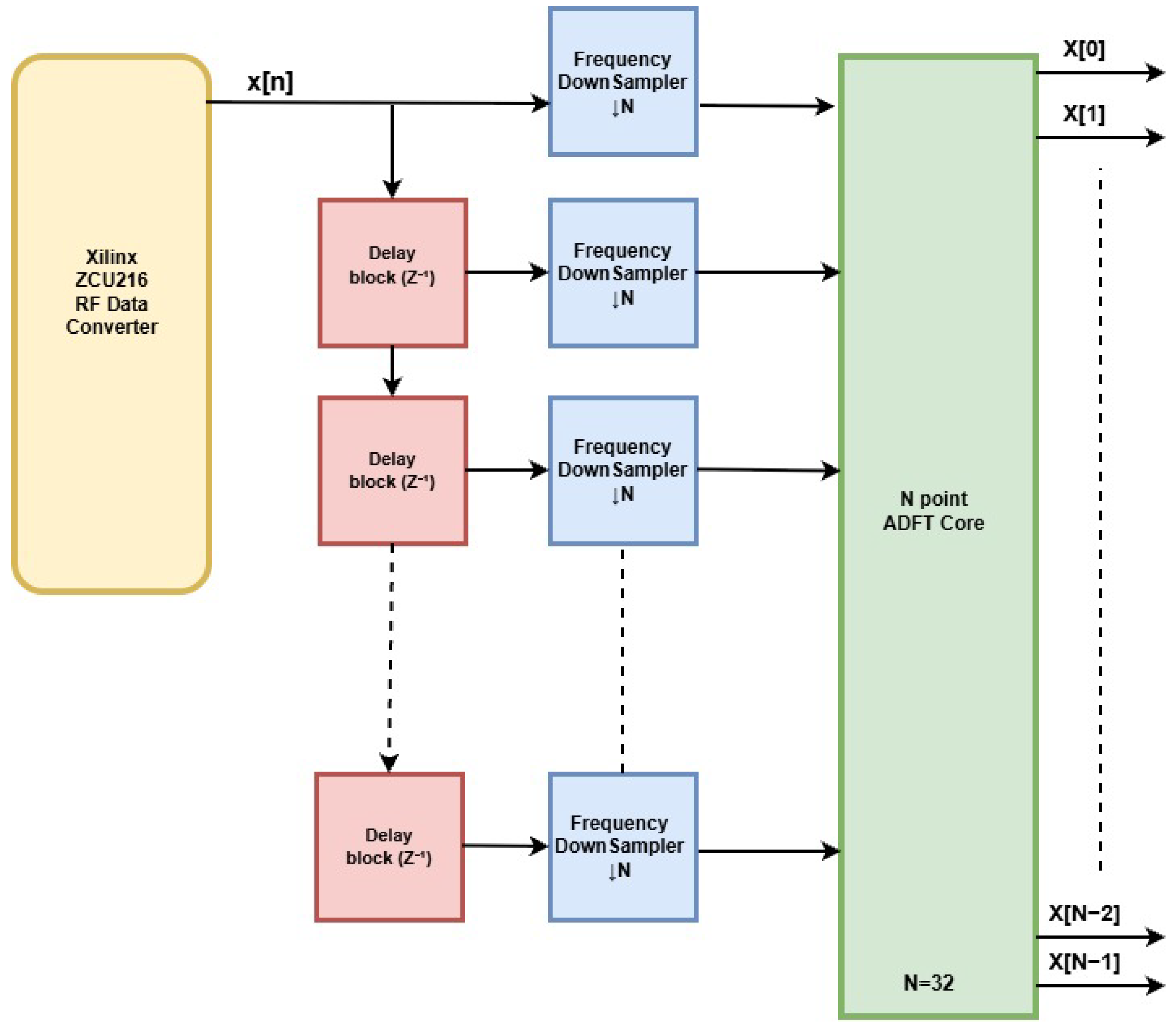
The proposed 32-point ADFT architecture was implemented and verified on the Xilinx Zynq UltraScale+ RF-SoC ZCU216 (AMD Xilinx, San Jose, CA, USA) evaluation platform. The implementation comprises an RF-ADC interface, a delay-and-decimation front end, and the proposed 32-point ADFT core, as illustrated in Figure 3.
Figure 3.
RF-SoC implementation of the proposed 32-point approximate discrete Fourier transform (ADFT) architecture, showing the radio-frequency data converter (RFDC) interface, the delay and decimation front end, and the ADFT processing core.
A wideband signal is digitized by an RF-ADC channel at a sampling rate of GS/s, and delivers the resulting sample stream to the programmable logic (PL) as eight 16-bit samples per 250 MHz fabric clock cycle. The transform operates on blocks of parallel samples, whereas the converter delivers a continuous serial stream. Therefore, a serial-to-parallel front end is required between the data converter and the transform core, which is realized by the cascade of unit-delay elements and frequency downsamplers, as shown in Figure 3.
The implemented design was verified on hardware using an on-chip waveform generator driving an RF-DAC output looped back to the RF-ADC input, with the resulting spectra written to an on-chip capture memory and read through the processing system. Even though the proposed architecture supports both real and complex input, all measurements reported in this work were obtained with a single real-valued RF-ADC channel as the signal source, with the quadrature input of the core held at zero. This configuration was used as a proof of concept and places no restriction on the architecture itself.
The scope of RTL generation was not limited to the transform. Every supporting module in the developed RF-SoC system was also produced by the agent, the delay-and-decimation front end that adapts the RF-ADC bus to the 32-sample block interface, the output packing logic, the on-chip waveform generator, and capture memory used for hardware verification. The human contribution is therefore limited to the specification, architectural decisions, and the verification strategy, while the RTL implementation of the complete system was generated by the agent.
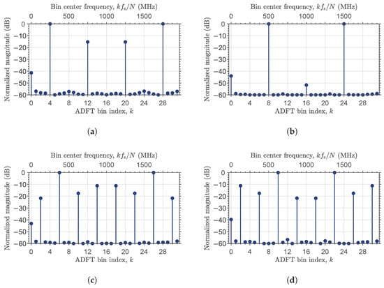
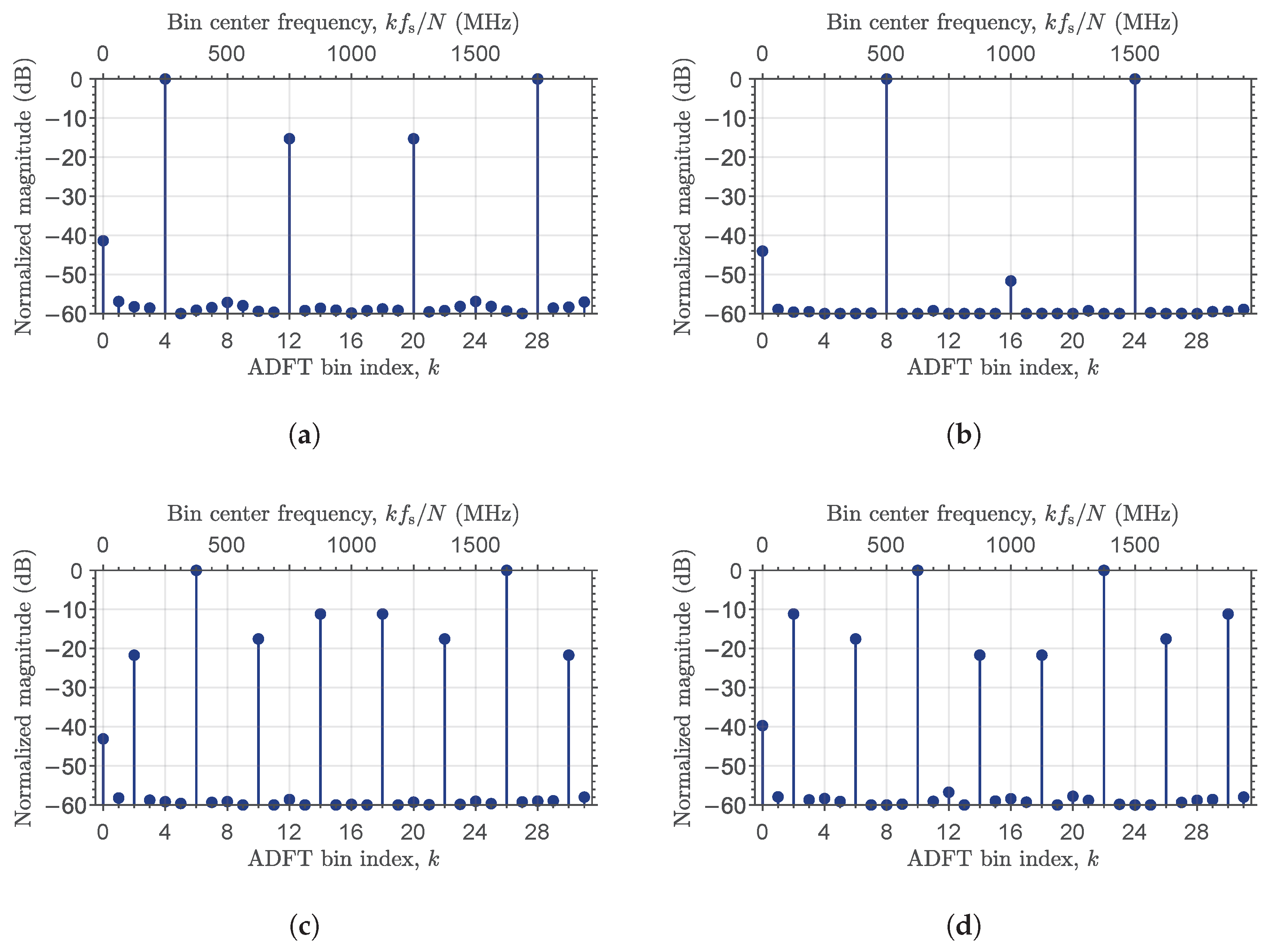
Three types of excitation signals were applied to the implemented system. The first consists of sinusoids placed exactly at bin centers, at 250, 375, 500 and 625 MHz, corresponding to bins 4, 6, 8 and 10 of the 32-point transform at a bin spacing of MHz. The measured spectra are shown in Figure 4. In every case, the peak appears at the expected bin and its conjugate mirror, and the approximation spurs predicted by appear at exactly the predicted bins and levels. The 500 MHz tone excites bins 8 and 24 alone and produces no approximation spur at all; the 250 MHz tone produces a single spur pair at bins 12 and 20 at dB, and the 375 and 625 MHz tones each produce three spur pairs, at , and dB relative to the peak. Across all four captures, the largest deviation between measurement and prediction on any non-null bin is 0.020 dB, the imbalance between a bin and its conjugate mirror does not exceed 0.01%, and at bins where the transform predicts an exact zero, the measured residual lies below dB, corresponding to the noise floor of the analog loopback path. The two exceptions are the DC bin, which reads between and dB due to the DC offset of the analog front end, and the bin of the 500 MHz capture at dB. Table 3 provides a summary of these results.
Figure 4.
Measured 32-point approximate discrete Fourier transform (ADFT) output spectra, normalized to the strongest bin: (a) 250 MHz tone, bin 4; (b) 500 MHz tone, bin 8; (c) 375 MHz tone, bin 6; (d) 625 MHz tone, bin 10.
Table 3.
Measured results for bin-centered tones, compared bin by bin against .
The design was synthesized and implemented in Xilinx Vivado 2020.2 for the XCZU49DR-2 device (AMD Xilinx, San Jose, CA, USA). When synthesized without the normalization and the output stages, the eight-stage transform occupies 14,146 LUTs and 20,822 flip-flops and no DSP slices or block RAMs, confirming that the factorization is realized entirely in general-purpose logic. The complete ADFT core, which includes the normalization and output stages, occupies 14,242 LUTs, 23,037 flip-flops, and 64 DSP48E2 slices, where the DSP slices are used only for constant multiplication by , which is applied separately to the real and imaginary parts of each of the 32 output bins.
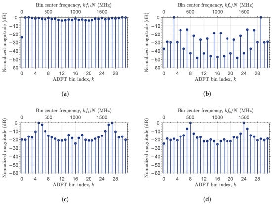
The second type of excitation is an impulse, for which all 32 bins are predicted to have the same magnitude. The measured response, shown in Figure 5a, is flat across bins 1 to 31 to within the resolution of the capture. Bin 0 lies approximately 24 dB below the remaining bins, which corresponds to the DC component and is not related to the transform.
Figure 5.
Measured 32-point approximate discrete Fourier transform (ADFT) output spectra, normalized to the strongest bin: (a) impulse excitation; (b) 189.45 MHz; (c) 339.84 MHz; (d) 480.47 MHz.
The third type consists of sinusoids placed away from bin centers, at 189.45, 339.84 and 480.47 MHz, which exercise the transform under spectral leakage. The measured responses remain in close agreement with the corresponding matrix predictions, with a mean deviation across the 32 bins ranging from 0.13% to 0.28% of the peak magnitude and a maximum deviation of 1.75%, and are presented in Figure 5b–d.
6.2. 28 nm CMOS Synthesis Results
The ADFT cores were synthesized with Cadence Genus (https://www.cadence.com/en_US/home/tools/digital-design-and-signoff/synthesis/genus-synthesis-solution.html, accessed on 18 September 2026) against TSMC 28 nm CMOS HPC+ standard-cell library, using 9-track cells with a 30 nm gate length and 140 nm contacted-poly pitch, characterized with composite current source (CCS) models at the typical corner, 1.0 V and 25 °C for transform sizes from 8 to 512 points. Table 4 reports cell count, total cell area and total power consumption for each size.
Table 4.
Synthesis results for the approximate discrete Fourier transform (ADFT) cores in 28 nm CMOS.
The synthesized architecture is fully parallel and fully pipelined. All N complex samples of a frame enter on the same clock edge, every stage is registered, and one complete frame is accepted per clock at fixed latency. A clock period of 10 ns, corresponding to 100 MHz, was applied to every transform size where every design met timing at this constraint, with no failing endpoints and no negative slack anywhere in the netlist.
7. Discussion
The results provide an affirmative answer to the central question presented in Section 1: a general-purpose LLM can generate correct hardware for an algorithm for which no public HDL implementation exists, provided that the algorithmic specification is supplied explicitly and can be independently verified. At every transform length, the generated RTL achieved bit-exact agreement with the independently developed MATLAB reference model with zero mismatches.
For the generated 32-point ADFT core, the RF-SoC measurements further confirmed that this equivalence was preserved through synthesis, place and route, and physical hardware operation. The primary role of the agent in this work was to translate the mathematical specification into pipelined fixed-point RTL, including word-length management with bit growth, latency balancing, and Cooley–Tukey composition.
RF-SoC measurements provide an additional verification mechanism because ADFT produces a characteristic spectral response. The 250 MHz excitation produced a spur pair at bins 12 and 20 at dB, while the 375 and 625 MHz excitations produced three spur pairs at , , and dB. The 500 MHz excitation did not produce a spur. The measured spur structure agreed with the predicted response to within dB. While replacing the customized algorithm with a standard FFT would still result the primary peak in the correct frequency bin, it would fail to produce this unique spur structure. Replicating this exact spur response thus confirms that the hardware faithfully implements the provisioned factorization rather than a familiar alternative.
The results also highlight two important aspects of the methodology, an executable mathematical specification and progressive composition. The sparse factorization matrices provide an unambiguous, machine-checkable reference, while the progressive approach uses each verified transform length as a building block for the next architecture. The synthesis results further show that the multiplierless property of the ADFT was preserved, with the eight-stage factorization synthesizing to zero DSP slices and the only multiplications are the constant multiplications related to the output-normalization.
Two significant strengths of a single agent-generated RTL description are highlighted in this work. Because each design was developed within a consistent context, the conventions established for the earliest modules carried into the later ones and formed a hierarchy, and no separate integration effort was required. Also, because no retraining, fine-tuning or custom agent framework was required, this approach can be used for any algorithm which has a formal specification.
Apart from the strengths, several pitfalls are also highlighted by this work. First, the generated RTL can be internally coherent but implement the wrong algorithm. In the control experiment of Section 3, the design synthesized without multipliers and passed its own bit-exact check while computing a completely different transform. Second, when both the design and the testbench are generated by the same agent, incorrect behaviour may not become visible at all, which is why verification in this work used a separate MATLAB framework built from the same factorization matrices; the errors found during verification were supplied back to the agent as feedback during the initial stages. Third, functional correctness does not imply design quality, as a bit-exact core may still be poorly pipelined or inefficient in power, performance and area, which are decisive in digital IC design [30,31,32,33].
Several limitations of this work can be listed: the provision of specification, architectural constraints, verification methodology, and MATLAB reference models by the human designer, making the present flow agent-assisted rather than fully autonomous. The study also considered a single algorithm family and a single LLM configuration, while the RF-SoC evaluation was limited to a single real-valued channel and selected excitation conditions.
Future work will extend the evaluation of agentic capabilities across the complete ASIC design flow, from RTL through synthesis, floorplanning, placement, clock-tree synthesis and routing to GDS-II, with the agent responsible not only for generating the HDL code but also for driving and optimizing each implementation stage [5,33,37]. Closing this tool-feedback loop would also allow power, performance and area to enter the generation objective rather than be measured after the fact, so that the agent performs optimization at each stage. In parallel, the methodology can be assessed under incomplete specifications and extended to other algorithm families for which no public implementation is available.
Author Contributions
Conceptualization, R.J.C. and A.M.; methodology, M.S.d.S.; software, M.S.d.S.; validation, M.S.d.S.; formal analysis, M.S.d.S.; writing—original draft preparation, M.S.d.S.; writing—review and editing, R.J.C. and A.M.; supervision, A.M.; funding acquisition, A.M. All authors have read and agreed to the published version of the manuscript.
Funding
This research was funded by the U.S. National Science Foundation (NSF) under Award No. 2504573 and by Brazilian CNPq under grant 315047/2023-2.
Data Availability Statement
The full transcript of the control experiment reported in Section 3.1.1 is available at https://claude.ai/share/e2cf2dda-9c52-4b69-9789-cadeee0b4ae2 (accessed on 18 September 2026).
Conflicts of Interest
The authors declare no conflicts of interest. The funders had no role in the design of the study; in the collection, analyses, or interpretation of data; in the writing of the manuscript; or in the decision to publish the results.
Abbreviations
The following abbreviations are used in this manuscript:
| ADFT | Approximate Discrete Fourier Transform |
| AI | Artificial Intelligence |
| ASIC | Application-Specific Integrated Circuit |
| CMOS | Complementary Metal-Oxide-Semiconductor |
| DFT | Discrete Fourier Transform |
| DIT | Decimation-in-Time |
| DSP | Digital Signal Processing |
| EDA | Electronic Design Automation |
| FF | Flip-Flop |
| FFT | Fast Fourier Transform |
| FPGA | Field-Programmable Gate Array |
| HDL | Hardware Description Language |
| IC | Integrated Circuit |
| IP | Intellectual Property |
| LLM | Large Language Model |
| LUT | Look-Up Table |
| PDE | Partial Differential Equation |
| PDK | Process Design Kit |
| RF | Radio Frequency |
| RF-ADC | Radio-Frequency Analog-to-Digital Converter |
| RF-DAC | Radio-Frequency Digital-to-Analog Converter |
| RF-SoC | Radio-Frequency System-on-Chip |
| RTL | Register-Transfer Level |
| TSMC | Taiwan Semiconductor Manufacturing Company |
| PPA | Power, Performance, Area |
References
- Pearce, H.; Tan, B.; Karri, R. DAVE: Deriving Automatically Verilog from English. In Proceedings of the 2020 ACM/IEEE Workshop on Machine Learning for CAD (MLCAD ’20), Virtual, 16–20 November 2020; ACM: New York, NY, USA, 2020; pp. 27–32. [Google Scholar] [CrossRef] [Scilit]
- Thakur, S.; Ahmad, B.; Pearce, H.; Tan, B.; Dolan-Gavitt, B.; Karri, R.; Garg, S. VeriGen: A Large Language Model for Verilog Code Generation. arXiv 2023, arXiv:2308.00708. [Google Scholar] [CrossRef] [Scilit]
- Liu, S.; Fang, W.; Lu, Y.; Zhang, Q.; Zhang, H.; Xie, Z. RTLCoder: Outperforming GPT-3.5 in Design RTL Generation with Our Open-Source Dataset and Lightweight Solution. In Proceedings of the 2024 IEEE LLM Aided Design Workshop (LAD); IEEE: Piscataway, NJ, USA, 2024; pp. 1–5. [Google Scholar] [CrossRef] [Scilit]
- Wu, H.; He, Z.; Zhang, X.; Yao, X.; Zheng, S.; Zheng, H.; Yu, B. ChatEDA: A Large Language Model Powered Autonomous Agent for EDA. IEEE Trans. Comput.-Aided Des. Integr. Circuits Syst. 2024, 43, 3184–3197. [Google Scholar] [CrossRef] [Scilit]
- Thakur, S.; Blocklove, J.; Pearce, H.; Tan, B.; Garg, S.; Karri, R. AutoChip: Automating HDL Generation Using LLM Feedback. arXiv 2024, arXiv:2311.04887. [Google Scholar] [CrossRef] [Scilit]
- He, Z.; Pu, Y.; Wu, H.; Qiu, T.; Yu, B. Large Language Models for EDA: Future or Mirage? ACM Trans. Des. Autom. Electron. Syst. 2025, 30, 1–53. [Google Scholar] [CrossRef] [Scilit]
- Deng, C.; Ho, C.T.; Ren, H. Artificial Intelligence-Assisted IC Design: Large language models and agentic systems for modern chip design. IEEE Solid-State Circuits Mag. 2026, 18, 41–51. [Google Scholar] [CrossRef] [Scilit]
- Liu, M.; Pinckney, N.; Khailany, B.; Ren, H. VerilogEval: Evaluating Large Language Models for Verilog Code Generation. arXiv 2023, arXiv:2309.07544. [Google Scholar] [CrossRef] [Scilit]
- Lu, Y.; Liu, S.; Zhang, Q.; Xie, Z. RTLLM: An Open-Source Benchmark for Design RTL Generation with Large Language Model. arXiv 2023, arXiv:2308.05345. [Google Scholar] [CrossRef] [Scilit]
- Cintra, R.J. An Integer Approximation Method for Discrete Sinusoidal Transforms. Circuits Syst. Signal Process. 2011, 30, 1481–1501. [Google Scholar] [CrossRef] [Scilit]
- Cintra, R.J. An Approximation for the 32-point Discrete Fourier Transform. arXiv 2024, arXiv:2407.12708. [Google Scholar] [CrossRef] [Scilit]
- Pan, J.; Zhou, G.; Chang, C.C.; Jacobson, I.; Hu, J.; Chen, Y. A Survey of Research in Large Language Models for Electronic Design Automation. ACM Trans. Des. Autom. Electron. Syst. 2025, 30, 1–21. [Google Scholar] [CrossRef] [Scilit]
- Ravindran, A.; Patra, A.; Babaey, V.; Purini, S. A Critical Review and Evaluation of LLMs for RTL Generation. IEEE Access 2026, 14, 28522–28539. [Google Scholar] [CrossRef] [Scilit]
- Yashchenko, D.S.; Romanov, A.Y.; Ziazetdinov, A.A.; Telpukhov, D.V.; Solovyev, R.A. Generation of Synthesizable Verilog Code from Natural Language Specifications. IEEE Access 2026, 14, 4990–5001. [Google Scholar] [CrossRef] [Scilit]
- ul Islam, M.; Sami, H.; Gaillardon, P.E.; Tenace, V. EDA-Aware RTL Generation with Large Language Models. arXiv 2024, arXiv:2412.04485. [Google Scholar] [CrossRef] [Scilit]
- Hu, Z.; Chen, J.; Lv, W.; Zhang, H.; Xia, Y. When LLMs Over-Answer: Measuring and Mitigating Quality Issues in LLM-Based Hardware Description Language Question Answering. arXiv 2026, arXiv:2607.17063. [Google Scholar] [CrossRef] [Scilit]
- Min, K.; Cho, K.; Jang, J.; Kang, S. REvolution: An Evolutionary Framework for RTL Generation driven by Large Language Models. In Proceedings of the 2026 31st Asia and South Pacific Design Automation Conference (ASP-DAC), Lantau, Hong Kong, 19–22 January 2026; pp. 282–288. [Google Scholar] [CrossRef] [Scilit]
- Liu, M.; Ene, T.D.; Kirby, R.; Cheng, C.; Pinckney, N.; Liang, R.; Alben, J.; Anand, H.; Banerjee, S.; Bayraktaroglu, I.; et al. ChipNeMo: Domain-Adapted LLMs for Chip Design. arXiv 2024, arXiv:2311.00176. [Google Scholar] [CrossRef] [Scilit]
- Blocklove, J.; Garg, S.; Karri, R.; Pearce, H. Chip-Chat: Challenges and Opportunities in Conversational Hardware Design. In Proceedings of the 2023 ACM/IEEE 5th Workshop on Machine Learning for CAD (MLCAD); IEEE: Piscataway, NJ, USA, 2023; pp. 1–6. [Google Scholar] [CrossRef] [Scilit]
- Pinckney, N.; Batten, C.; Liu, M.; Ren, H.; Khailany, B. Revisiting VerilogEval: A Year of Improvements in Large-Language Models for Hardware Code Generation. ACM Trans. Des. Autom. Electron. Syst. 2025, 30, 91. [Google Scholar] [CrossRef] [Scilit]
- Alberti-Binimelis, M.; Gutierrez-Gomez, C.; Garcia-Gasulla, D.; Parisi, E.; Moundir Ghorab, R.; Montenegro, O.; Homs, B.; Moreto, M.; Kestor, G. Revisiting TuRTLe: A Comprehensive Evaluation of LLMs for RTL Generation. ACM Trans. Des. Autom. Electron. Syst. 2026, accepted. [Google Scholar] [CrossRef] [Scilit]
- Zang, Z.; Song, Y.; Wang, A.; Ling, B.W.K.; Sun, Q.; Lei, Z.; Yang, F.; Zhuo, C.; Luo, J. The Dawn of Agentic EDA: A Survey of Autonomous Digital Chip Design. arXiv 2026, arXiv:2512.23189. [Google Scholar] [CrossRef] [Scilit]
- Devgan, A. Powering the AI Supercycle: Design for AI and AI for Design. In Proceedings of the 2026 IEEE International Solid-State Circuits Conference (ISSCC), San Francisco, CA, USA, 15–19 February 2026; Volume 69, pp. 26–34. [Google Scholar] [CrossRef] [Scilit]
- Morsy, M.M. AI-on-Chip Systems: A Cross-Layer Review of Architectures, Interconnects, Design Automation, and Embedded Intelligence. Electronics 2026, 15, 2645. [Google Scholar] [CrossRef] [Scilit]
- Patra, A.; Rout, S.; Ravindran, A. AiEDA: Agentic AI Design Framework for Digital ASIC System Design. arXiv 2024, arXiv:2412.09745. [Google Scholar] [CrossRef] [Scilit]
- Zhao, Y.; Zhang, H.; Huang, H.; Yu, Z.; Zhao, J. MAGE: A Multi-Agent Engine for Automated RTL Code Generation. In Proceedings of the 2025 62nd ACM/IEEE Design Automation Conference (DAC), San Francisco, CA, USA, 22–25 June 2025; pp. 1–7. [Google Scholar] [CrossRef] [Scilit]
- Eryilmaz, C. ChipCraftBrain: Validation-First RTL Generation via Multi-Agent Orchestration. arXiv 2026, arXiv:2604.19856. [Google Scholar] [CrossRef] [Scilit]
- Tang, J.; Qin, J.; Thorat, K.; Zhu-Tian, C.; Cao, Y.; Zhao, Y.K.; Ding, C. HiVeGen—Hierarchical LLM-based Verilog Generation for Scalable Chip Design. In Proceedings of the 2025 IEEE International Conference on LLM-Aided Design (ICLAD), Stanford, CA, USA, 26–27 June 2025; pp. 30–36. [Google Scholar] [CrossRef] [Scilit]
- Li, C.; Chen, C.; Pan, Y.; Xu, W.; Liu, Y.; Chang, K.; Wang, Y.; Wang, M.; Li, H.; Han, Y.; et al. AutoSilicon: Scaling Up RTL Design Generation Capability of Large Language Models. ACM Trans. Des. Autom. Electron. Syst. 2025, 30, 97. [Google Scholar] [CrossRef] [Scilit]
- Tasnia, K.; Garcia, A.; Farheen, T.; Rahman, S. VeriOpt: PPA-Aware High-Quality Verilog Generation via Multi-Role LLMs. In Proceedings of the 2025 IEEE/ACM International Conference on Computer Aided Design (ICCAD), Munich, Germany, 26–30 October 2025; pp. 1–9. [Google Scholar] [CrossRef] [Scilit]
- Wang, Y.; Shi, Q.; Li, S.; Hu, Q.; Yin, X.; Guo, B.; Han, X.; Sun, M.; Su, J. VeriAgent: A Tool-Integrated Multi-Agent System with Evolving Memory for PPA-Aware RTL Code Generation. arXiv 2026, arXiv:2603.17613. [Google Scholar] [CrossRef] [Scilit]
- Thorat, K.; Zhao, J.; Liu, Y.; Hasan, A.; Peng, H.; Xie, X.; Lei, B.; Ding, C. LLM-VeriPPA: Power, Performance, and Area Optimization aware Verilog Code Generation with Large Language Models. In Proceedings of the 2025 ACM/IEEE 7th Symposium on Machine Learning for CAD (MLCAD), Santa Cruz, CA, USA, 8–10 September 2025; pp. 1–7. [Google Scholar] [CrossRef] [Scilit]
- Ping, H.; Zhang, P.; Li, S.; Yang, W.; Cheng, A.; Duan, S.; Zhang, X.; Bogdan, P. COEVO: Co-Evolutionary Framework for Joint Functional Correctness and PPA Optimization in LLM-Based RTL Generation. arXiv 2026, arXiv:2604.15001. [Google Scholar] [CrossRef] [Scilit]
- Madanayake, A.; Ariyarathna, V.; Madishetty, S.; Pulipati, S.; Cintra, R.J.; Coelho, D.; Oliviera, R.; Bayer, F.M.; Belostotski, L.; Mandal, S.; et al. Towards a Low-SWaP 1024-Beam Digital Array: A 32-Beam Subsystem at 5.8 GHz. IEEE Trans. Antennas Propag. 2020, 68, 900–912. [Google Scholar] [CrossRef] [Scilit]
- Ariyarathna, V.; Madanayake, A.; Tang, X.; Coelho, D.; Cintra, R.J.; Belostotski, L.; Mandal, S.; Rappaport, T.S. Analog Approximate-FFT 8/16-Beam Algorithms, Architectures and CMOS Circuits for 5G Beamforming MIMO Transceivers. IEEE J. Emerg. Sel. Top. Circuits Syst. 2018, 8, 466–479. [Google Scholar] [CrossRef] [Scilit]
- Lawrance, K.; Madanayake, A.; Hariharan, S.; Cintra, R.J. Approximate DFT Based Fourier Neural Operators for ML-Based PDE Solution at Linear Complexity. In Proceedings of the 2025 IEEE 68th International Midwest Symposium on Circuits and Systems (MWSCAS), Lansing/E. Lansing, MI, USA, 10–13 August 2025; pp. 449–452. [Google Scholar] [CrossRef] [Scilit]
- Tarighat, M.; Gubbi, K.I.; Javidnia, N.; Marosok, N.; Zibakhsh-Shabgahi, S.; Halm, M.; Nejad, M.P.S.; Rafatirad, S.; Koushanfar, F.; Homayoun, H. Closing the Loop: Overcoming the Tool-Feedback Gap in Agentic Hardware Design. In Proceedings of the 2026 27th International Symposium on Quality Electronic Design (ISQED), San Francisco, CA, USA, 8–10 April 2026; pp. 1–8. [Google Scholar] [CrossRef] [Scilit]



Disclaimer/Publisher’s Note: The statements, opinions and data contained in all publications are solely those of the individual author(s) and contributor(s) and not of MDPI and/or the editor(s). MDPI and/or the editor(s) disclaim responsibility for any injury to people or property resulting from any ideas, methods, instructions or products referred to in the content. |
© 2026 by the authors. Licensee MDPI, Basel, Switzerland. This article is an open access article distributed under the terms and conditions of the Creative Commons Attribution (CC BY) license.