


Abstract
An experimental study was conducted to investigate the flexural behavior of continuous beams strengthened with precast concrete plates. Ten rectangular concrete beams with a cross-section of 210 × 150 mm and a total length of 2400 mm were tested under four-point loads. One specimen, without any strengthening, acted as the control, while the remaining nine were strengthened at both the positive and negative moment zones. The variables in this study were: strengthening plate thickness, length, type of bonding (epoxy or mechanical connector), bonding method (surface bonding or 10 mm grooving), type of concrete used (UHPC, SFRC, or SIFCON), and finally, the steel fiber ratio. The failure mode, cracking modes, ultimate load, load–deflection curve, stiffness and ductility were analyzed. The results showed the effectiveness of the strengthening methods, as they improved the flexural strength of the beams by 15.7% to 53%, as well as their stiffness by 15% to 173.8%, and reduced crack propagation. Also, decreasing the thickness and length of plates reduced the flexural strength by 7.28% and 23.5%, respectively. When the bonding methods were compared, the beam with mechanical bonding showed 5.7% more flexural strength than the one using epoxy. However, it was noted that all cracks in the strengthening plates were located at the bolt positions. Additionally, the use of SIFCON plates enhanced flexural strength more than UHPC and SFRC plates. However, for the SFRC plate, increasing the steel fiber content from 1.5% to 2% improved the strength by 1.2%, but this high percentage also caused cracking in the SFRC plate due to the inhomogeneity of the concrete mixture. As for the initial stiffness, the sample in which epoxy was used showed the highest value, with an increase of 173.8%, due to the uniform bonding at the connection surface. Finally, it was observed that the reference beam had the highest ductility due to the high ultimate displacement resulting from the numerous cracks that occurred in the beam, which were reduced in the strengthened beams.
1. Introduction
Concrete constructions are made to work effectively for the duration of their design life. However, the structure may be weakened by a number of issues, including poor construction, defective materials, design mistakes, neglect of continuous maintenance, changes in use, and altered environmental conditions. As a result, strengthening work is often required [1,2,3]. Additionally, strengthening is essential not only for maintenance but also for improving the overall performance and strength of structures [4]. For rehabilitation, it is therefore essential to choose materials that are both economical and durable [5,6]. High-performance concrete, which is cement-based and has superior ability to resist stresses and impacts as well as greater compressive and tensile strength than regular concrete, has been the subject of several recent studies [7,8,9]. This is explained by the use of steel fibers in its composition, which are dispersed uniformly throughout the base material and greatly enhance the tensile qualities of the concrete [10,11,12]. Furthermore, this kind of concrete has low water permeability and strong durability since fine cracks smaller than 0.05 mm have no effect on these properties [13,14,15]. Additionally, after heat treatment, its compressive and tensile strengths exceed 150 MPa and 7 MPa, respectively. Additionally, its creep and shrinkage coefficients are relatively small [16,17]. Ultra-high-performance concrete (UHPC) is a suitable option for strengthening damaged concrete structures because of these mechanical properties [18,19].
There are numerous studies on the use of high-performance concrete, which was first used in Switzerland to strengthen reinforced concrete structures [20]. These studies used both experimental and numerical methods to estimate the behavior of beams strengthened with UHPC, whether for flexural or shear strength, while accounting for variables such as strengthening location, thickness, and others.
Paschalis et al. [21] investigated that the use of 50 mm thick high-performance concrete with reinforcement to strengthen concrete beams increased load-bearing capacity and stiffness. Also increasing the UHPC thickness enhances durability and shear strength [22,23]. Abbas et al. [24] also investigated the strengthening of RC beams by applying different thicknesses of UHPC layer along the flexural zone and the inclusion of 10 mm diameter GFRP reinforcement in various numbers and lengths. The results revealed that the beam, strengthened with only a 50 mm thick layer of high-performance concrete, raised the ultimate load by 64%, while adding three full-length GFRP bars increased this percentage to 257% when compared to the reference beam. Shorter bars increased load-bearing capacity, but they also caused debonding failure of the strengthening at the ends.
Zhang et al. [25] discovered that using UHPC enhanced the load-bearing capacity of damaged reinforced concrete beams while reducing crack propagation. These properties were further enhanced by the addition of steel wire mesh for strengthening. Also, Mirdan and Saleh [26] and Zhu et al. [27] reached the same result when applying this technique to undamaged RC beams. Luo et al. [28] investigated the effect of UHPC strengthening on beams with varied degrees of pre-existing damage. They discovered that raising the reinforcement ratio and strengthening thickness enhanced load-bearing capacity, especially in beams with less damage. Mario [29] and Noshiravani [30] investigated that UHPC increased ultimate load-bearing, rotational strength, and ductility for the RC beams.
Balla et al. [31] investigated the effect of combining GFRP and UHPC to strengthen RC beams and discovered that adding GFRP increased flexural strength by 129%. Chen et al. [32] studied improving the performance of RC beams subjected to loads and chloride corrosion, finding that adding a UHPC layer significantly improved the performance of the elements. Mirdan and Saleh [33] found that using UHPC improved the strength and crack-propagation limit of RC beams. Although the presence of construction joints weakened this technique, this weakness was overcome by the use of the steel/GFRP bars. Feng et al. [34] also found that using prestressed UHPC to strengthen RC beams improves stiffness, flexural strength, and crack resistance.
Other strengthening methods include steel fiber-reinforced concrete and the use of SIFCON material. Jabbar et al. [35] investigated the strengthening of RC beams using SIFCON with different thicknesses and amounts of steel fibers. They discovered that increasing layer thickness or fiber content in the mix resulted in the beams having a higher ultimate load-bearing capability than the reference beam. Marid and Vahidi [36] also investigated how SIFCON could be used to strengthen lightweight beams. They discovered that SIFCON increased flexural strength, particularly when applied to three sides (U-shape) of a beam with high steel fiber content. Furthermore, Taher and Dawood [37] discovered that employing precast SIFCON as shear reinforcement for RC beams increased shear strength and delayed the first crack appearance.
There are also many concrete materials that can be used for strengthening; Said et al. [38] also found that high-performance fiber-reinforced concrete is highly effective for shear strengthening in concrete beams, as well as in terms of ductility, toughness, and initial strength. Imoh et al. [39,40] found that the 10% replacement of Portland cement with Metakaolin (MK) increased compressive strength from 35.6 MPa to 53.9 MPa, in addition to improving tensile and flexural strength. The use of snail shells and Waste Glass Cullet in concrete mixture also improves the strength of structures.
Regarding bonding techniques, there are several methods, such as epoxy bonding, mechanical bonding, and sandblasting [41]. Lafta et al. [42] and Jassim [43] revealed that the epoxy was efficient for attaching GFRP strengthening to RC beams, since no segregation occurred. Li et al. [44] observed, in some cases, that high-strength bolts failed in tension and shear. Shehata et al. [45] showed the effectiveness of shear connectors in bonding steel and concrete plates to RC beams.
This study conducted experiments on ten continuous reinforced concrete beams using three types of precast strengthening concrete plates: ultra-high-performance concrete (UHPC), steel fiber reinforced concrete (SFRC), and SIFCON. The bonding techniques varied, including mechanical bonding (shear connectors) and epoxy bonding. The direct bonding to the beam surface, or 10 mm grooves in the concrete cover, was utilized. The percentage of steel fiber and strengthening plate dimensions, such as thickness and length, were also examined. The finding discussed the ultimate load, load–deflection behavior, crack mode, ductility, and stiffness. This topic has been extensively studied using multiple techniques because research on continuous beams is relatively limited compared to other beam types. Even the available research has focused on limited techniques, used a single type of concrete, or relied on a single traditional bonding method. This leaves a knowledge gap regarding the impact of varying concrete types, dimensions, and bonding methods on the flexural behavior of continuous beams. Integrating all these variables provides a broader database that enables engineers to select optimal solutions for strengthening continuous beams, enhancing their flexural strength, and improving their structural efficiency in real-world applications.
2. Experimental Work
2.1. Materials
2.1.1. Cement
Portland cement of the Mabrouka type, whose properties are detailed in Table 1 and Table 2, was used. These properties were determined in accordance with ASTM C150/C150M-24 specifications [46] by laboratory tests at the University of Basrah, College of Engineering.
Table 1.
Physical characteristics of cement.
Table 2.
Cement’s primary component and structure.
2.1.2. Aggregate
The sand and gravel used were obtained from the Zubair area in southern Basra. Sand with a fineness modulus of 2.8 and gravel with a diameter of 25 mm were used, as specified in the standard (ASTM C33/C33M-24a) [50]. Table 3 shows the properties of both the sand and gravel, which were tested according to the standard (ASTM C128) [51].
Table 3.
Fine and coarse aggregate’s physical characteristics.
2.1.3. Superplasticizer
To improve the workability of concrete used for strengthening, a superplasticizer (F-180 G) was used in the proportions shown in Table 4, in accordance with ASTM C494 [52].
Table 4.
Mix design for different types of concrete.
2.1.4. Fiber
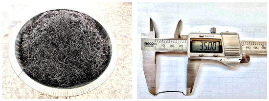
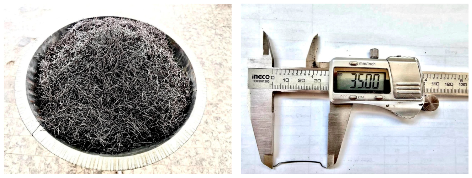
Steel fibers are commonly used in concrete mixes to increase their strength, elasticity, and crack resistance. In this study, 1.5% and 2% fiber volume fractions of 35 mm long, 0.5 mm diameter end hooks steel fibers with a 60 aspect ratio, tensile strength of 1200 MPa, and density of 7860 kg/m3 were used in strengthening concrete mixes (see Figure 1).
Figure 1.
End hooks steel fibers.
2.1.5. Epoxy Adhesive
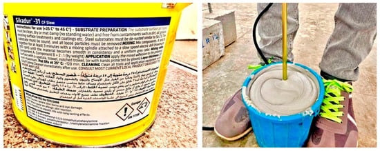
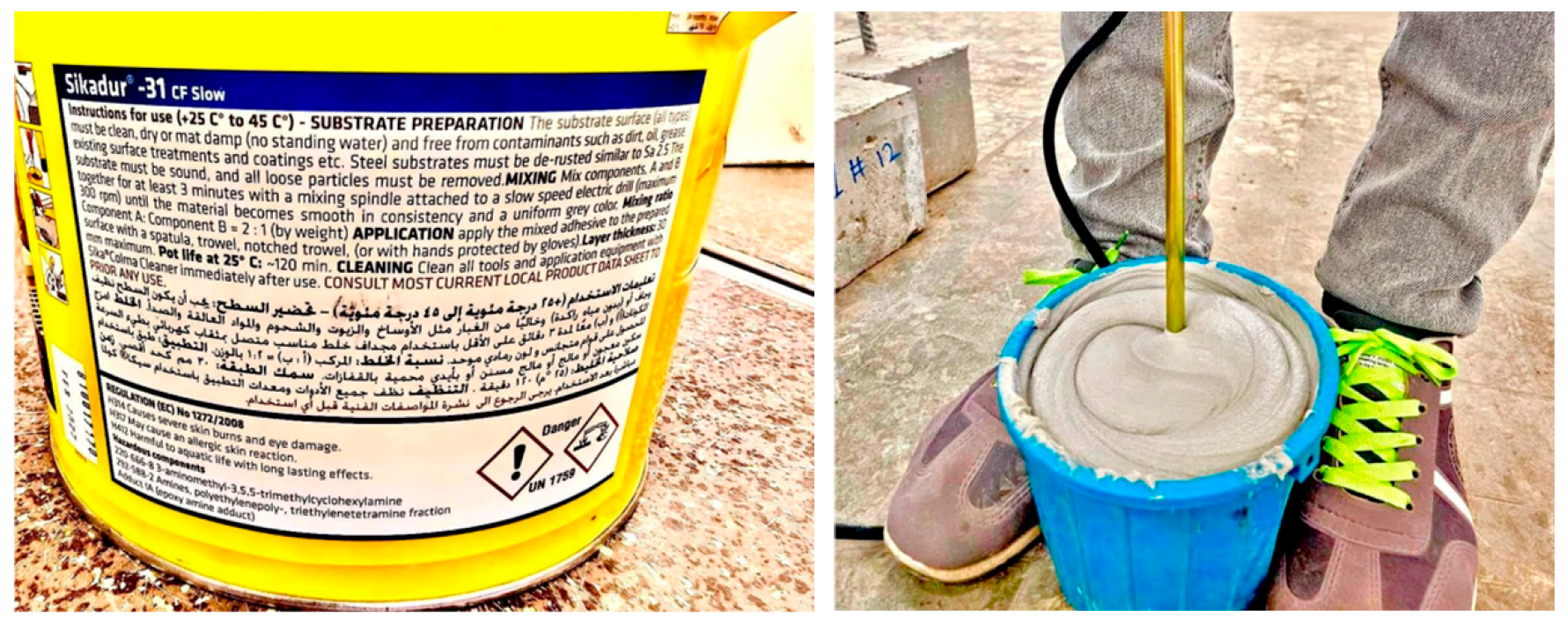
To achieve a strong bond, Sika epoxy adhesive, consisting of epoxy resin and hardener combined in a 2:1 ratio and mixed for at least three minutes as shown in Figure 2. Due to its high load-transfer capacity, it was used to fix the precast concrete strengthening plates to continuous beams.
Figure 2.
Preparing the adhesive material.
2.1.6. Shear Connectors
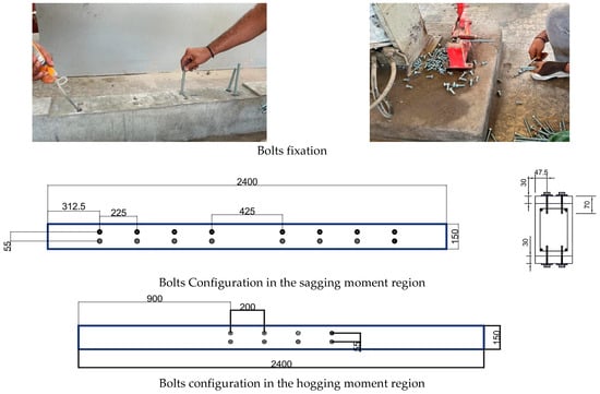
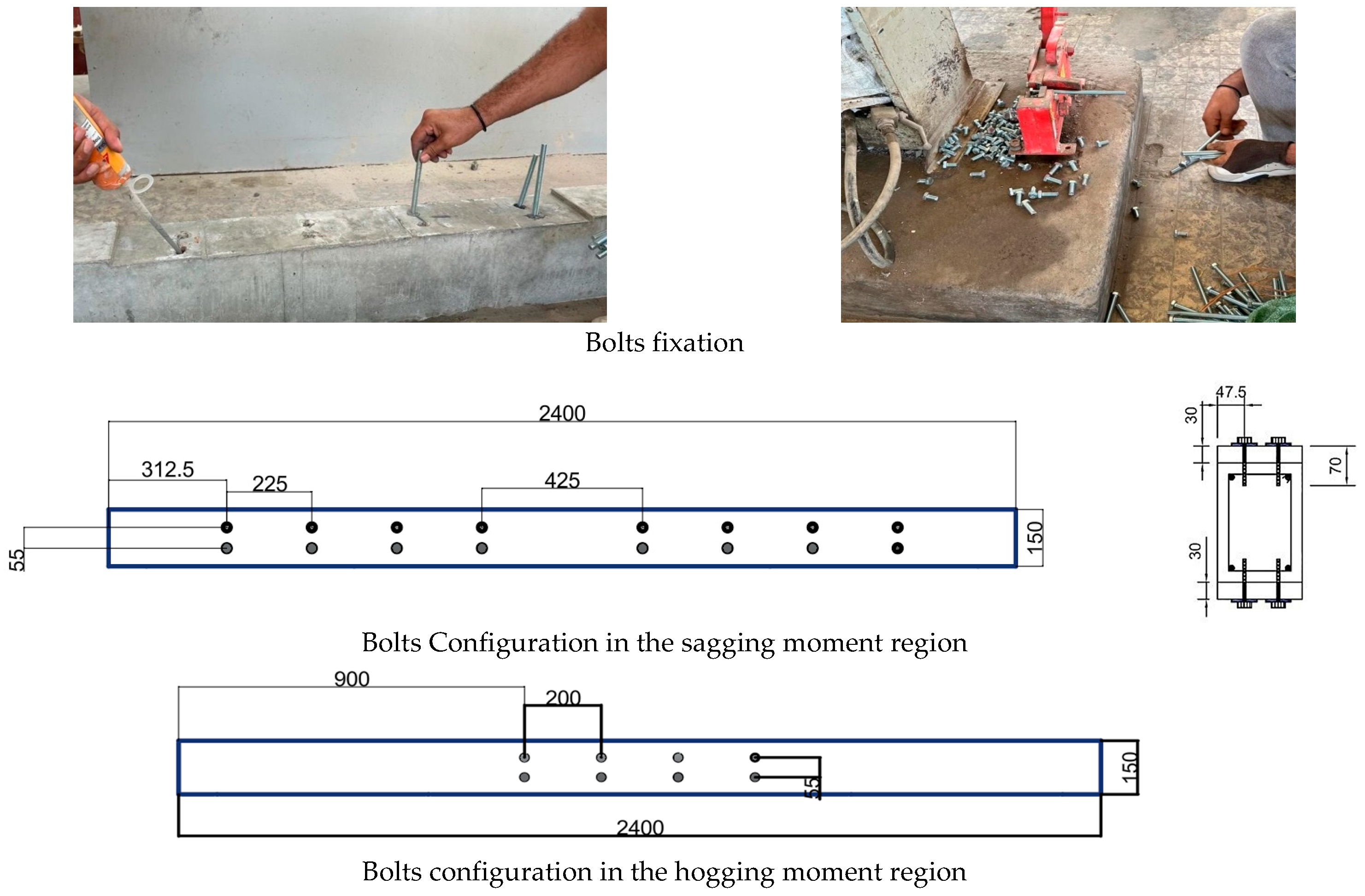
One of the important structural elements used in bonding is the shear connector, which transfers shear forces between the strengthening plates and the continuous reinforced concrete beams and also ensures effective bonding without any slippage. In this study, bolts of 70 mm length and 10 mm diameter were used. The bolts were spaced according to ACI Committee Report 355 [53], and the bolt depth was determined in accordance with Chapter 17 of the ACI 318-14 [54]. The RC beam was bored with holes that were 12 mm in diameter and 40 mm deep. After that, the bolts were put into these epoxy-filled holes as shown in Figure 3. The bolts were put through the strengthened plates once they had cured [55].
Figure 3.
Shear connector details.
2.1.7. Concrete Mixture
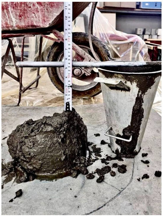
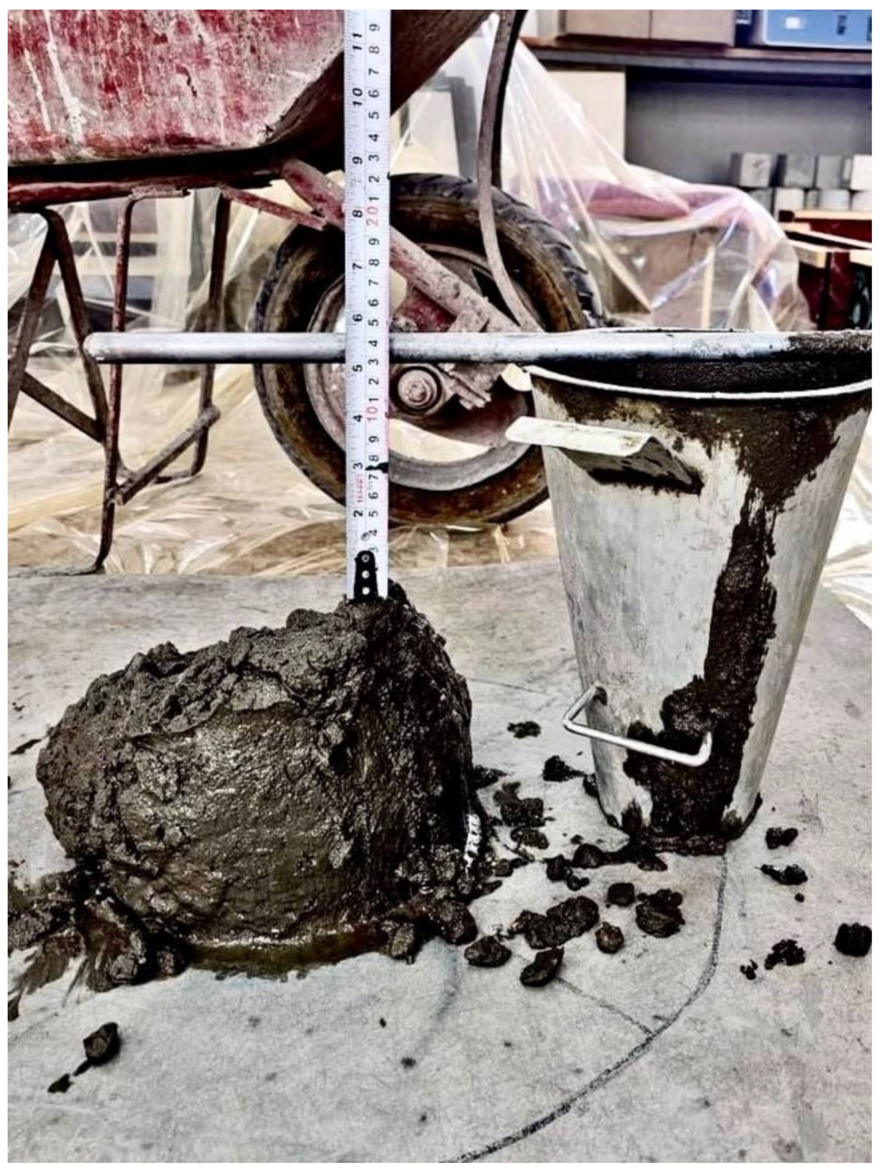
Four concrete mixtures were utilized in this experiment; the mixing proportions are illustrated in Table 4. In order to cast the ten continuous concrete beams, normal concrete with a compressive strength of 35 Mpa and a 160 mm slump was used. The compressive strength was found by testing six cubes and three cylinders according to ASTM C39/C39M-24 [56] and BS EN 12390-3 [57] specifications. While the slump was calculated using the traditional method according to ASTM C143 [58] (see Figure 4).
Figure 4.
Slump test.
The UHPC, SIFCON, and SFRC were the other three mixes used for strengthening plates. Materials with certain characteristics, such as a silica fume with a diameter of less than 1 micrometer (sika fume S 92 D) and sand (Sikador 507) with a 0.3–0.7 mm particle size were utilized to create these mixtures. The compressive strength results of strengthening concrete were measured according to ASTM C39/C39M-24 [56] and were 120 Mpa for UHPC and 58 Mpa for SIFCON, and 31 Mpa and 33 Mpa for SFRC with 1.5% and 2% steel fiber, respectively.
2.2. Test Specimens
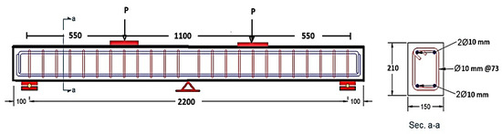
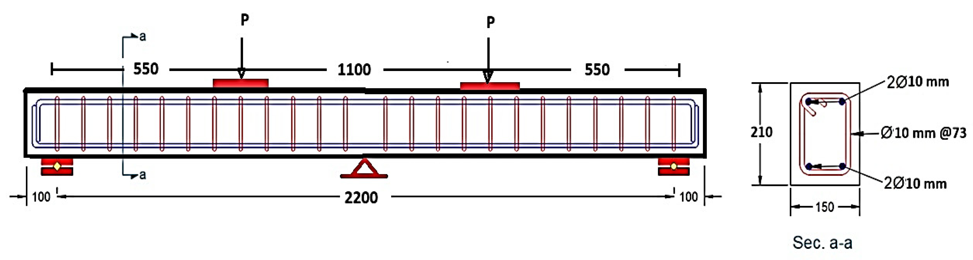
A four-point load test was used to study the flexural behavior of ten continuous reinforced concrete beams that were designed according to the ACI-318 [54], with a rectangular cross-section (150 × 210 mm), a beam length of 2400 mm, and an effective span of 1100 mm (see Figure 5). Two 10 mm diameter bars were used as longitudinal reinforcement for the beams, and 10 mm diameter bars were used at a 73 mm space, with a yield strength of 450 MPa, to ensure flexural failure. Nine of the beams were strengthened with different concrete types, varying lengths, thicknesses, and steel fiber ratios, in addition to a reference beam.
Figure 5.
Reinforcement details.
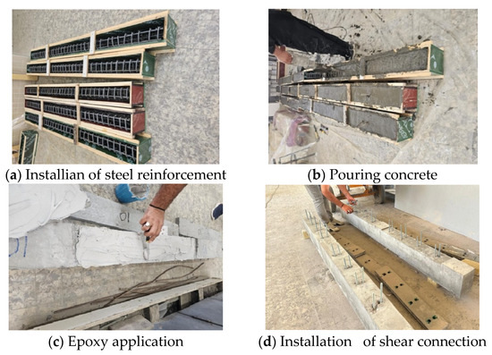
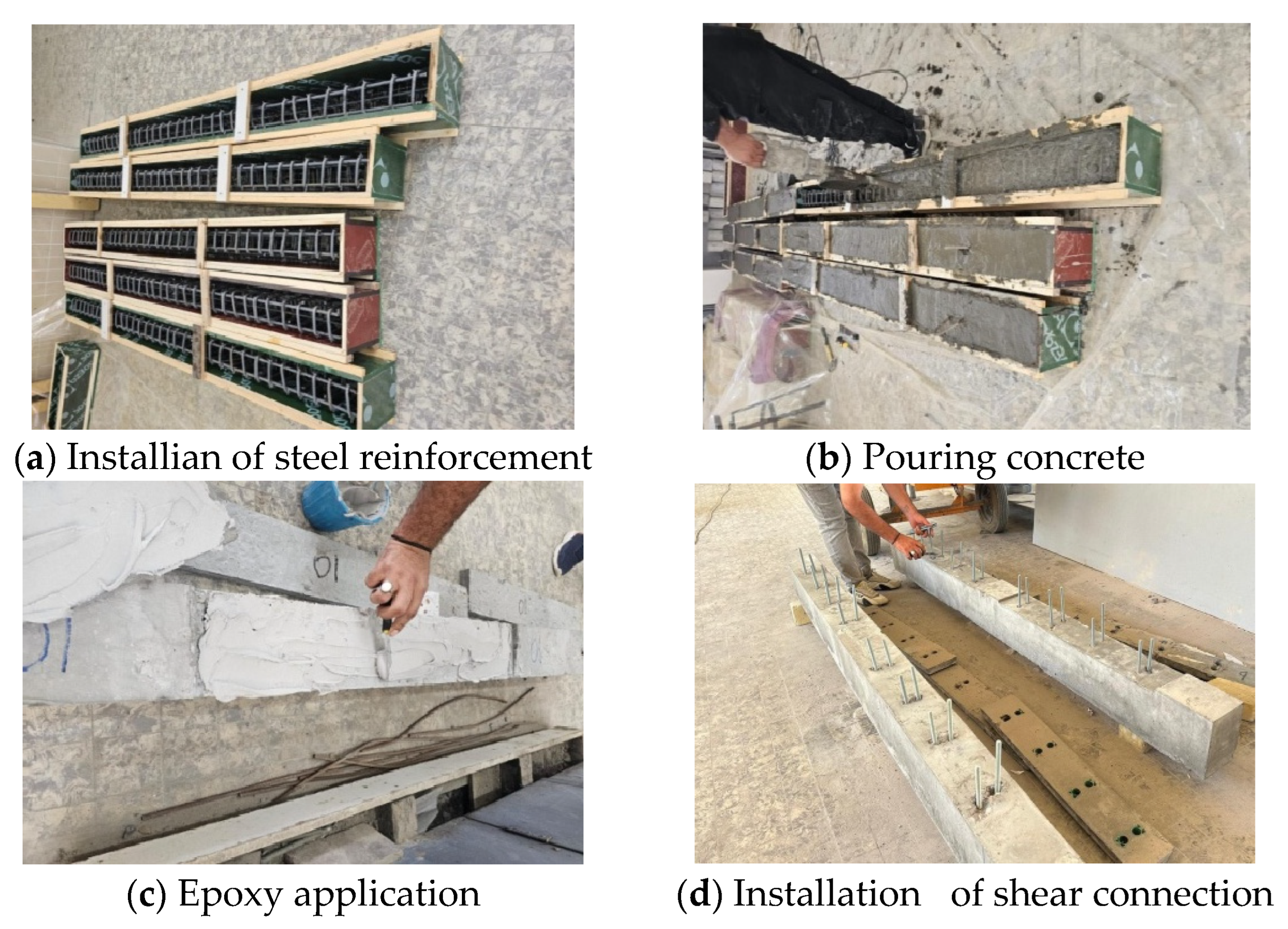
Initially, the longitudinal reinforcement and strips were placed in wooden formwork, and then concrete was poured. After 24 h, the beams were removed and left to cure for 28 days. Following this, precast strengthening plates were installed using epoxy or shear connectors, as shown in Figure 6.
Figure 6.
Details of beams’ preparation.
2.3. Strengthening Schemes
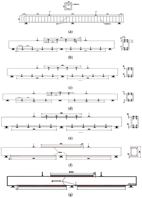
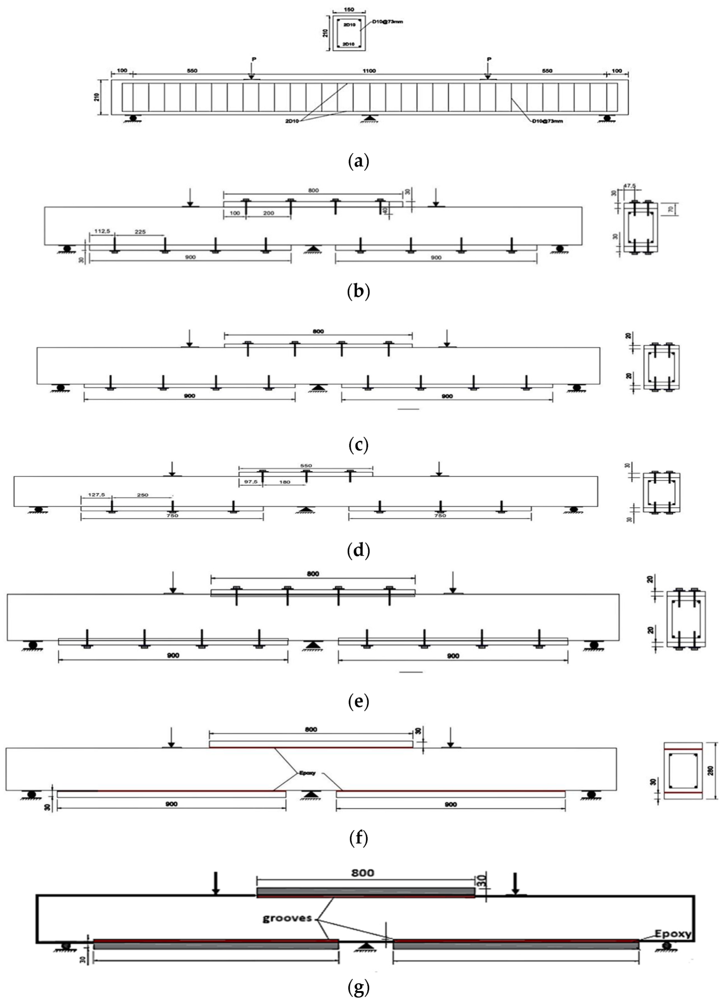
Ten identical specimens of continuous concrete beams were prepared. One beam was used as a reference to study the behavior of beams under flexure before strengthening. The remainder was strengthened in the tension zones and included seven strengthened specimens using SFRC, with some differences. The first specimen (SF-SH) included a 900 mm long strengthening in the sagging moment zone with a thickness of 30 mm and an 800 mm long strengthening in the hogging moment zone with a thickness of 30 mm. The percentage of steel fiber was 1.5%. The other specimens had the same specifications and dimensions, but with some differences. Specimen (SF-SH-DVF) included a change in the percentage of steel fiber to 2%, specimen (SF-SH-DTH) included a decrease in the thickness of the strengthening layer to 20 mm, and specimen (SF-SH-DL) included a change in the length of the strengthening from 900 to 750 mm and from 800 to 550 mm. In all four of these specimens, the connection method was the same, which was the use of shear connectors. However, the connection method differed in the remaining three, as specimen (SF-EP) used epoxy to connect the strengthened concrete layer to the beams, and specimen (SF-IRS) involved grooving a 10 mm deep before fixing it with epoxy. While the seventh sample had its strengthening connected using a shear connector, this was done after creating grooves 10 mm deep. The use of UHPC in strengthening the ninth beam was studied; finally, in the tenth beam, strengthened with a SIFCON layer with a 7% steel fiber content, both the ninth and tenth beams had the same layer dimensions as the (SF-SH) beam. Table 5 and Figure 7 show the details of those beams.
Table 5.
Continuous RC beams strengthen details.
Figure 7.
Strengthen techniques of beams: (a) control beam, (b) SF-SH, SF-SH-DVF, UHP-SH, and SIF-SH, (c) SF-SH-DTH, (d) SF-SH-DL, (e) SF-GG, (f) SF-EP, and (g) SF-IRS.
2.4. Test Setup
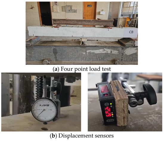
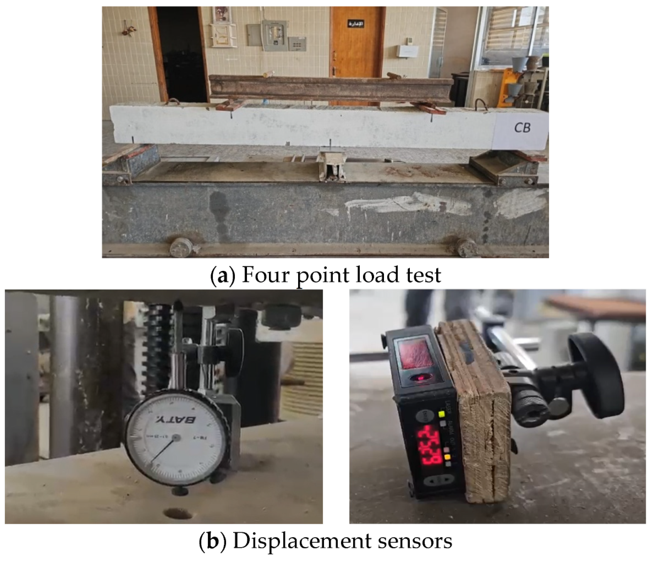
Figure 8 illustrates the laboratory testing procedure for beams at the College of Engineering, University of Basrah. A four-point load was applied, with a horizontal clear distance of 1100 mm and a total beam length of 2400 mm, of which 100 mm was taken as the distance from each end to the support. A hydraulic device with a force of 2000 kN was used. In order to study the structural behavior and monitor the displacement at the initial cracking and during the loading phase, two measuring devices were fixed to the lower surface of the beam at the midpoint of each span.
Figure 8.
Laboratory testing details.
3. Results
3.1. Crack Pattern and Failure Mode
Figure 9, Figure 10, Figure 11, Figure 12, Figure 13, Figure 14, Figure 15, Figure 16, Figure 17 and Figure 18 and Table 6 illustrate that the failure pattern for all samples was indeed due to flexure, but under different loads, as will be explained in detail below.
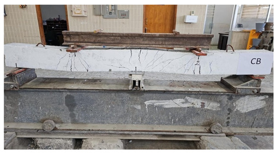
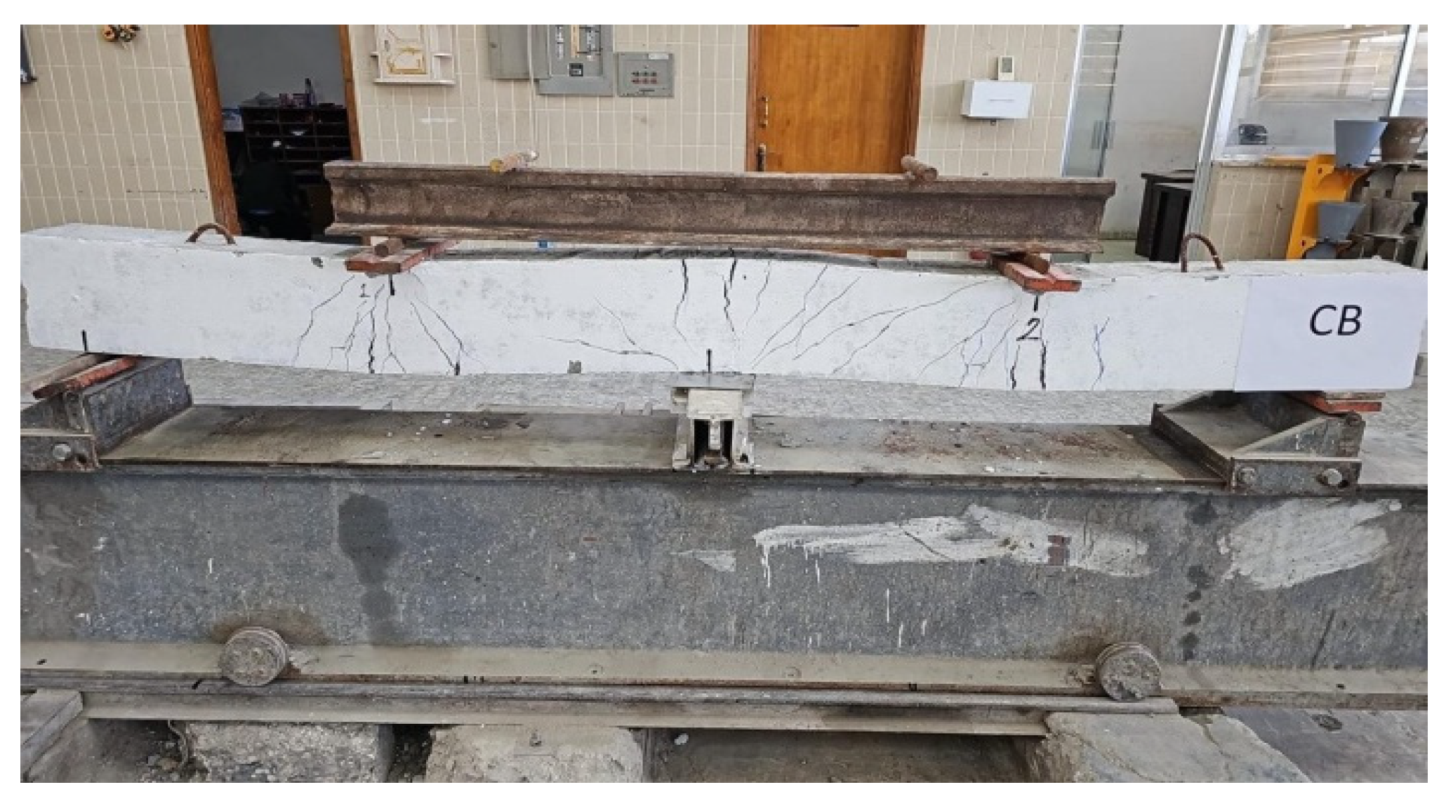
Figure 9.
Failure mode and crack propagation of the control beam.
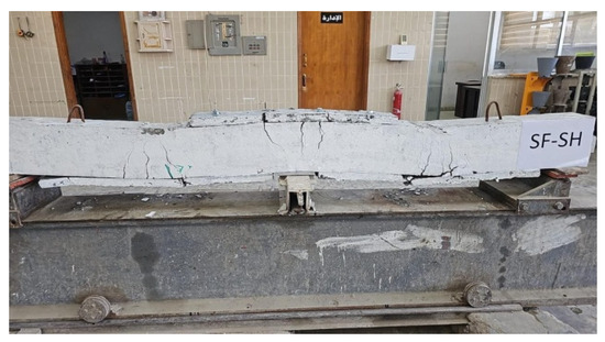
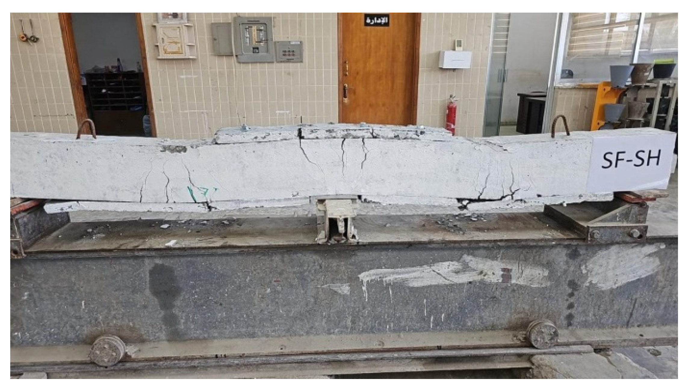
Figure 10.
Failure mode and crack propagation of the SF-SH beam.
Figure 11.
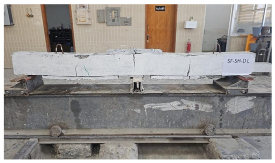
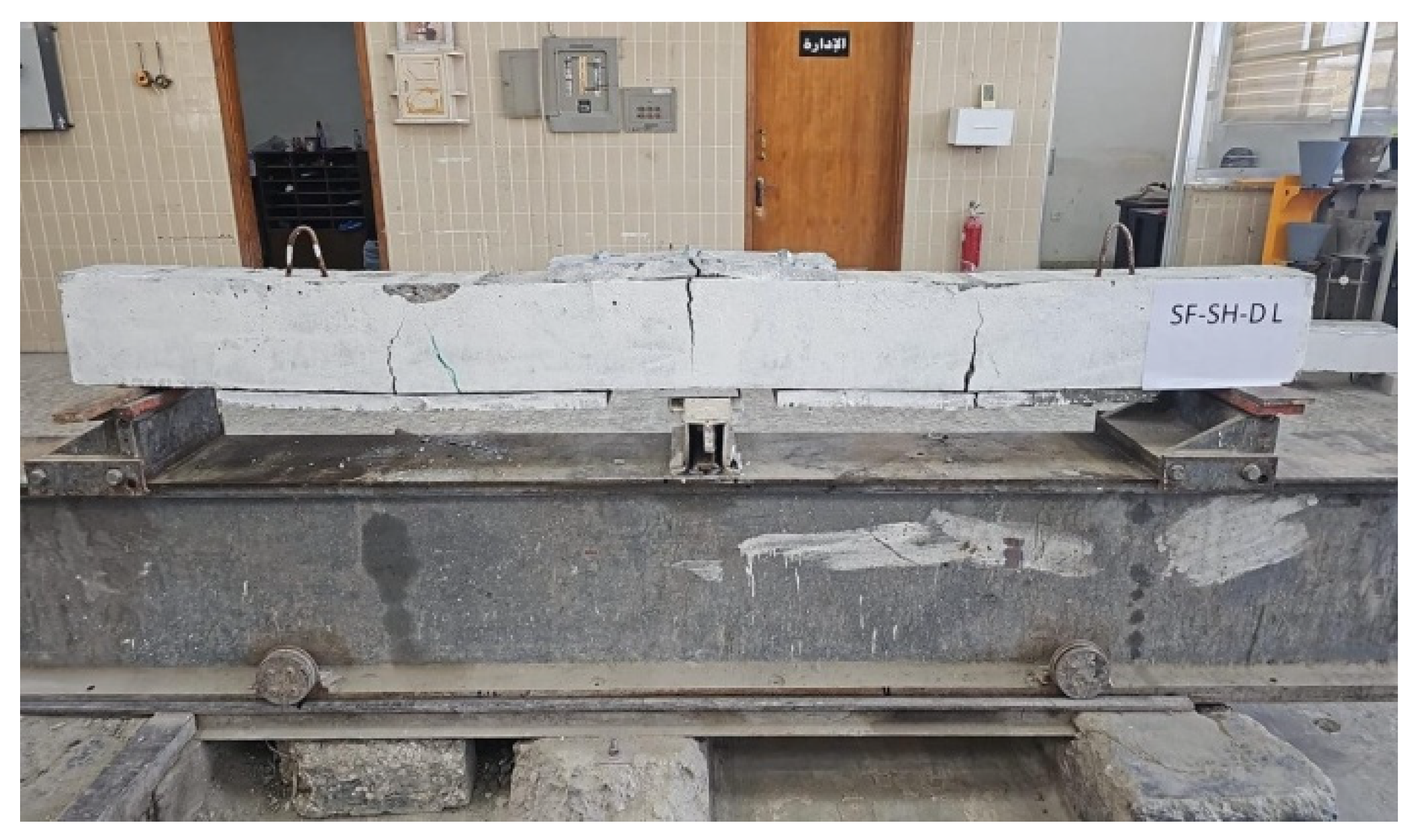
Failure mode and crack propagation of the SF-DL beam.
Figure 12.
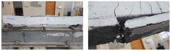
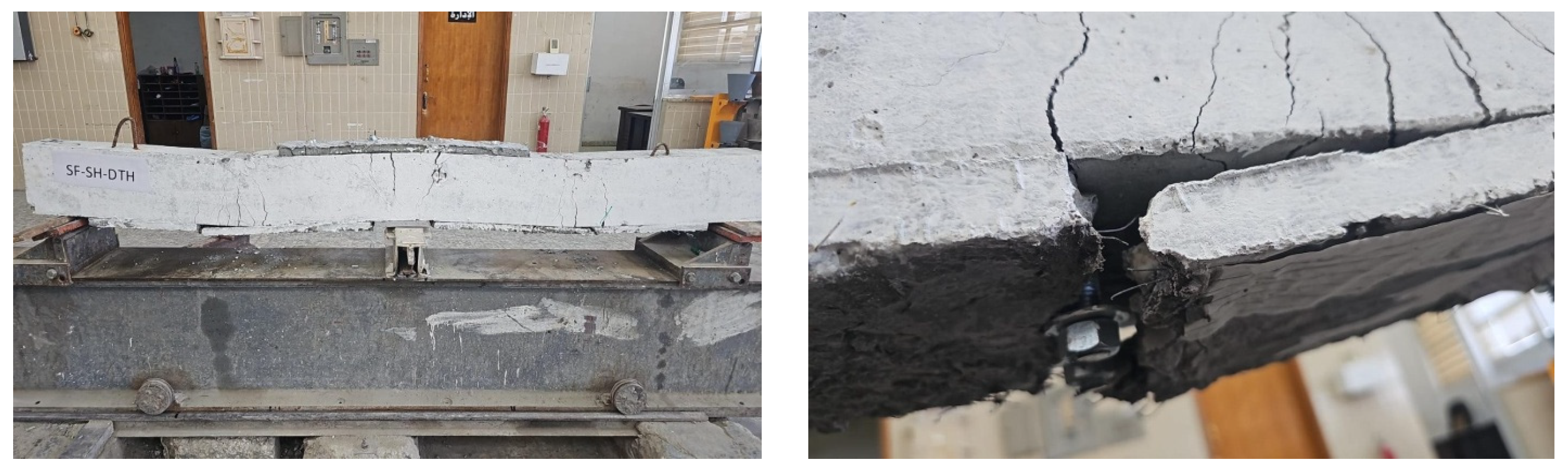
Failure mode and crack propagation of the SF-SH-DTH beam.
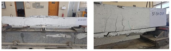
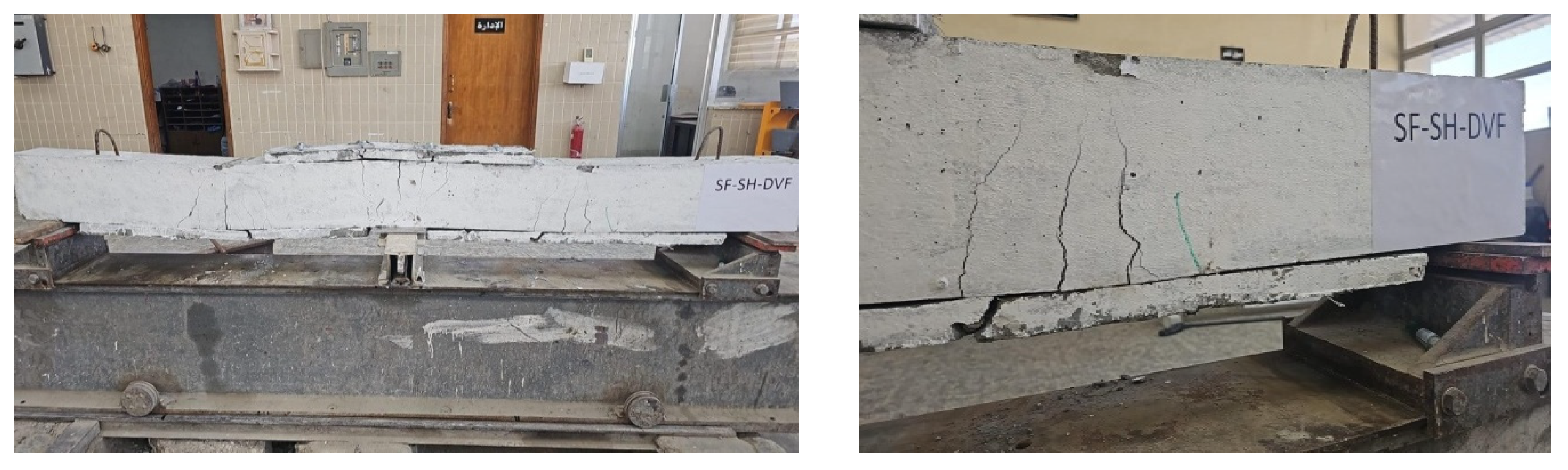
Figure 13.
Failure mode and crack propagation of the SF-SH-DVF beam.
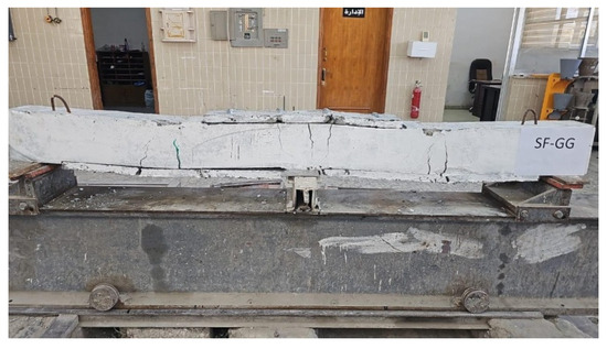
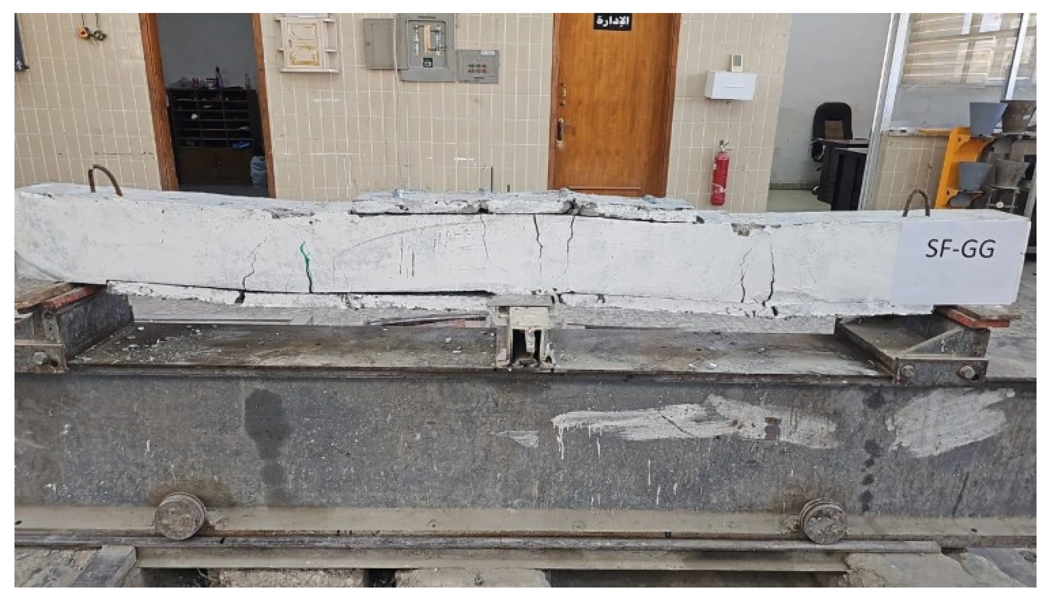
Figure 14.
Failure mode and crack propagation of the SF-GG beam.
Figure 15.
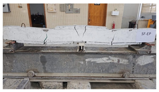
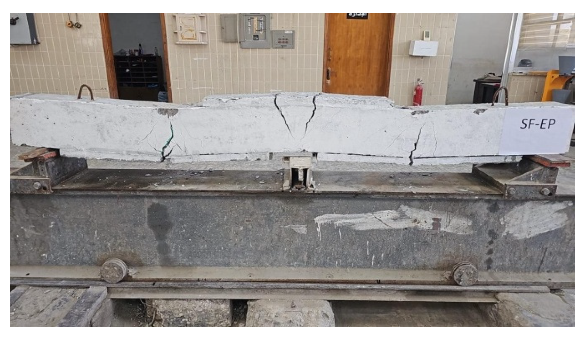
Failure mode and crack propagation of the SF-EP beam.
Figure 16.
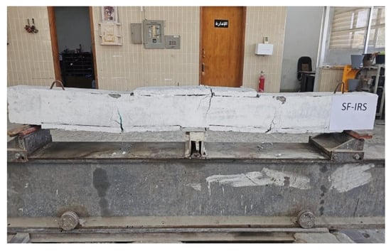
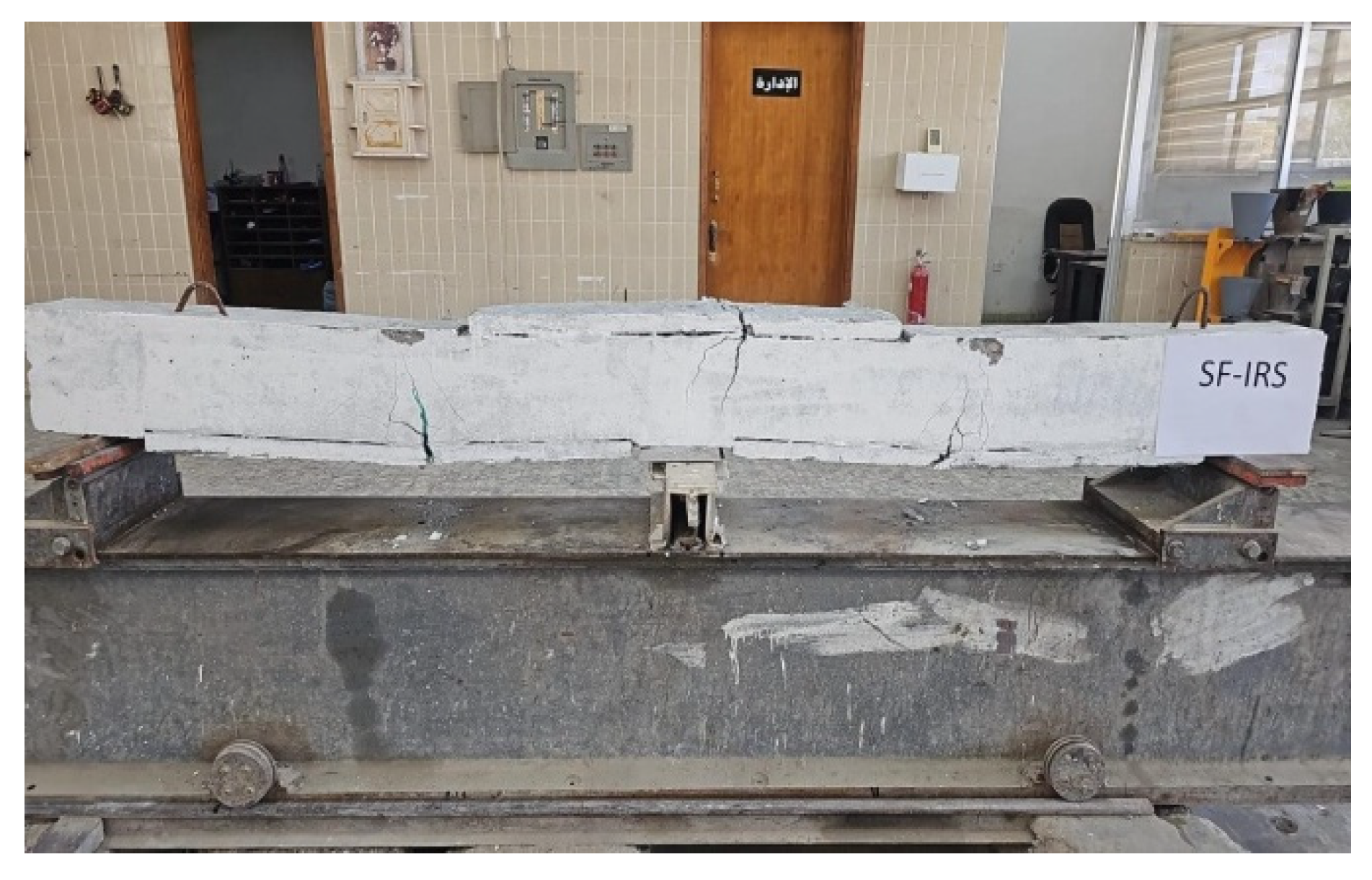
Failure mode and crack propagation of the SF-IRS beam.
Figure 17.
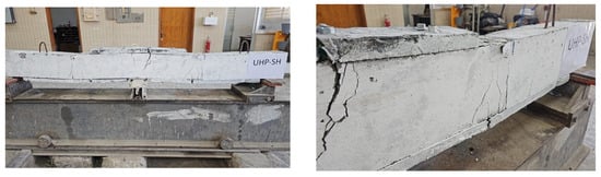
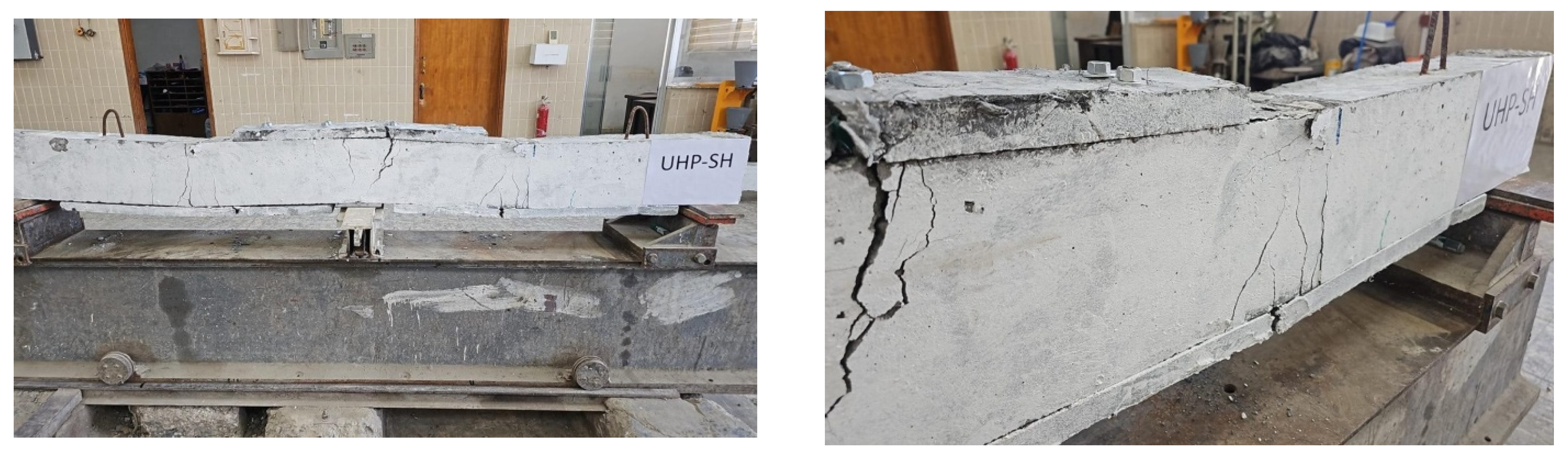
Failure mode and crack propagation of the UHP-SH beam.
Figure 18.
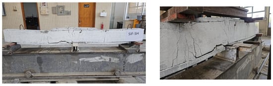
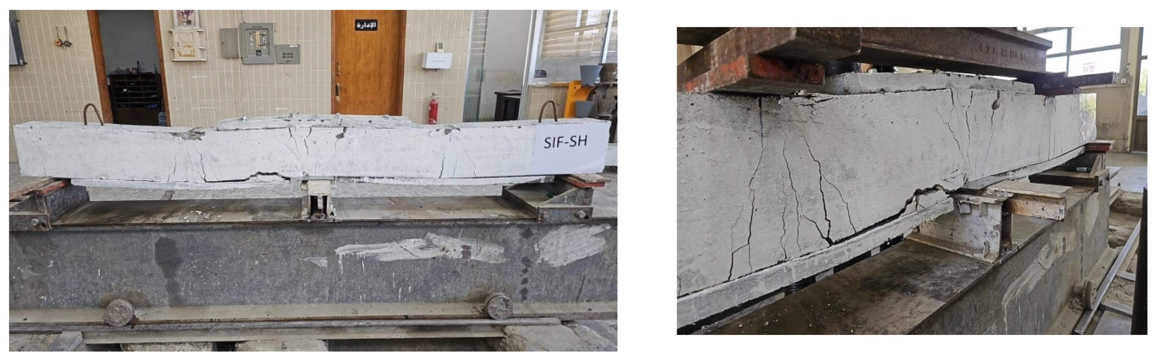
Failure mode and crack propagation of the SIF-SH beam.
Table 6.
Test results of continuous beam.
3.1.1. Control Beam (CB)
For the reference specimen (CB) shown in Figure 9, the first crack appeared at a load of 39.34 kN in the sagging moment region on the left side, followed by a second crack on the right side, along with other cracks. At a load of 68.67 kN, the first crack appeared in the hogging moment region above the middle support. All cracks continued to extend and widen until they reached 2 mm in the positive moment region and 3 mm in the negative moment region. As mentioned previously and as expected, the specimen failed due to flexure.
3.1.2. SF-SH
The use of steel fiber-reinforced concrete strengthening (SFRC) improved the load-bearing capacity and performance of the beams, as the number, width, and extent of cracks were reduced (see Figure 10). The first crack in the beam (SF-SH) appeared in the middle of the positive moment zone on the left side, above the strengthening layer, under a load of 89.3 kN. Subsequently, these cracks continued to appear, but they did not extend to the depth of the beam, unlike those that appeared in the reference sample. It was observed that the cracks spread through the strengthening layer at the shear connectors at 280.5 kN, leading to their fracture. Localized breakage of the concrete cover was also observed below the load zone and on the right side above the external reinforcement, in addition to isolation of the SFRC plate end. Under a load of 315 kN, the beam reached its maximum load capacity which is 51.2% higher than the load for the CB. The crack width was 3 mm in the positive moment zones and 2 mm in the negative moment zone.
3.1.3. SF-SH-DL
Although reducing the length of the SFRC plate from 900 mm to 750 mm and from 800 mm to 550 mm resulted in a 15.7% improvement in load-bearing capacity compared to the reference specimen, as it withstood a maximum load of 241 kN, this increase was still 23.5% less than that of the (SF-SH) beam with the longer strengthening length. While cracking was less widespread, three deep cracks appeared in the strengthening zones: two in the positive moment zone below the load application points and one above the middle support. The first crack appeared at a load of 54.6 kN and continued to widen until a load of 229.6 kN, at which point the top SFRC plate fractured. This fracture was an extension of the beam fracture and measured 4 mm wide at the maximum load. The cracks in the positive moment zone were also 3 mm wide (see Figure 11). This clearly indicates that using a longer strengthening significantly improved resistance. The effect of external strengthening length was also observed in previous studies, which reached the same conclusion [59].
3.1.4. SF-SH-DTH
The sample shown in Figure 12 was studied to investigate the effect of reducing the SFRC thickness from 30 mm to 20 mm. The result was a 40.2% increase in load-bearing capacity compared to the reference sample, but simultaneously a 7.28% decrease compared to the 30 mm thick (SF-SH) beam. Regarding its behavior under load, the first crack appeared at a load of 63.8 kN, followed by numerous cracks, though fewer in number than in the reference beam. These cracks extended almost the entire depth of the beam, and with increasing load, they widened and increased in size until they reached the bottom SFRC plate, which broke at a load of 270.3 kN in the shear connector area. When the load reached 315 kN, the beam failed. The crack widths at this stage were 2 mm in the positive moment zone on the left side and 3 mm on the right side and in the negative moment zone. It is worth noting that although reducing the thickness negatively affected the strength, it simultaneously increased the flexibility of the strengthening plate, as it was observed that it bent better with the beam, and the upper SFRC plate did not break.
3.1.5. SF-SH-DVF
This specimen investigated increasing the percentage of steel fiber in the SFRC strengthening layer to 2%. It was observed that the beam’s load-bearing capacity increased by 53% compared to the reference beam and by 1.2% compared to the beam (SF-SH), which contains 1.5% steel fiber. The first crack appeared at a load of 66.4 kN, which is higher than that of the reference beam. The increased steel percentage also made the specimens more flexible under bending loads, as it was observed to bend more with the beam than the other studied beams. Furthermore, the cracks that appeared were thin and discontinuous or interconnected. The first crack appeared at the bottom of the beam in the positive moment zone and continued to spread as the loads increased. Upon failure, all strengthening cracked in the bolt connection areas, but these cracks did not extend to the beam cracks. At a failure load of 318.8 kN, the crack width on the right side of the positive moment zone reached 2 mm, and 3 mm on the left side and in the negative moment zone.
The study of the model shown in Figure 13 found that increasing the proportion of steel fibers improved the bending strength by no more than 1.8%, but at the same time, cracks appeared in the SFRC plate due to the heterogeneity resulting from the high proportion of steel fibers.
3.1.6. SF-GG
In this specimen, 10 mm deep grooves were drilled in the sequence shown in Figure 7e. The SFRC plate was then fixed using shear connectors. This strengthening technique improved the beam’s flexural strength by 21.8% compared to the reference beam but decreased it by 19.4% compared to the ungrooved (SF-SH) beam. The first crack in this specimen appeared at a 54 kN load in the positive moment region, a lower load than that of the other strengthened beams studied. As the loads increased, the number and width of cracks increased, with some extending into the SFRC plate at a 253.8 kN load. The crack width increased to 3 mm in both the positive and negative moment regions at maximum load (see Figure 14).
The improvement in this technique was less than the others, possibly due to the larger grooved area as well as the use of a shear connector, as a previous study on the effect of grooving area on load-bearing strength showed that increasing the grooving area reduces the improvement in load-bearing capacity [60].
3.1.7. SF-EP
In this sample, the difference lies in the method of connecting the strengthening to the beam. Epoxy adhesive was applied directly to the beam after cleaning, instead of a shear connector. The results showed that using the SFRC plate improved the beam capacity, increasing it by 42.6% compared to the reference beam. However, using epoxy resulted in a 5.7% lower capacity compared to the beam (SF-SH) connected with a shear connector. When loads were applied, it was observed that the epoxy-bonded SFRC plates acted as a single unit with the beam, as the connection was homogeneous. The same cracks extended from the beam to the plates, and no plate debonding occurred. The first crack appeared at a load of 57.4 kN and continued to extend. At a load of 159.4 kN, the cracks persisted throughout all the SFRC plates till the failure occurred at 297 kN. It was also observed that the cracks were large and not widespread, with the crack width at failure reaching (3.2) mm on the left and right sides in the positive moment zone, respectively, and 3 mm in the negative moment zone as shown in Figure 15.
This sample study showed that using epoxy reduces the improvement in load-bearing capacity compared to using shear connectors, even though no insulation was achieved when using epoxy.
3.1.8. SF-IRS
The bonding mechanism in this sample involved creating a 10 mm deep, 150 mm wide groove, within which the SFRC plate was fixed using epoxy. This technique resulted in a 29.8% increase in strength compared to the reference sample and a 14.2% decrease compared to the (SF-EP) sample, where the SFRC plate was bonded directly with epoxy. Due to this decrease, extensive grooving is not recommended as it reduces the effective concrete surface area, thus weakening the beam strength. However, this method increased the stability of the strengthening, which in turn increased the first crack load. This crack appeared at a load of 89.3 kN in the positive moment region, where the crack formed in both the SFRC plate and the beam, as they acted as a single unit. The cracks continued to widen until failure at 270.4 kN, but no strengthening debonding occurred. As can be seen in Figure 16, the number of cracks was lower compared to the (SF-EP) beam. Under failure load, the crack width was 3 mm in both the positive and negative moment zones.
Also, compared to the SF-GG beam, there was a 6.5% increase in load-bearing capacity. Therefore, using epoxy is a better option than shear connectors when employing near-surface techniques.
3.1.9. UHP-SH
This model, shown in Figure 17, investigated the change in the strengthening concrete type using high-performance concrete with dimensions shown in Table 5. The load-bearing capacity of the beam increased by 41% compared to the reference sample, while it decreased by 6.7% compared to the (SF-SH) sample due to the substantial fissure in the beam, leading to increased strains in the strengthened plate [61]. Under applied loads, the cracks in the positive moment zone were observed to be narrow and non-interconnected or non-spread. The first crack appeared at a load of 62.6 kN and continued to widen until it reached the high-performance concrete layer, which fractured at a load of 293.8 kN. The crack widths were equal to 3, 2, and 2 mm in the left positive moment zone, the right positive moment zone, and the negative moment zone, respectively.
3.1.10. SIF-SH
SIFCON is a good strengthening material that has been studied previously in numerous research projects. In this study, the sample shown in Figure 18 was strengthened with SIFCON as one of the variables and compared to the other two strengthening materials. The results indicated that it increased the beam load-bearing capacity by 52.5% compared to the control beam and by 0.83% and 8.7% compared to samples SF-SH and UHP-SH, respectively. When loads were applied, the first crack appeared at 102 kN in the positive moment region, indicating that this type of strengthening delayed crack appearance compared to the others. With increasing load, the cracks widened to 3 mm at the 317.6 kN failure load, without any cracking or debonding of the strengthening plate at the positive moment region.
The research investigation employed a single specimen for each variable due to the involvement of numerous factors, comparing each with the reference beam (CB) and the SF-SH beam, which acted as a reference to change one strength variable at each beam. The beams SF-SH-DVF, SF-SH-DTH, and SF-SH-DL differed from sample SF-SH in steel fiber content, strengthening thickness, and strengthening length, respectively. Sample SF-GG had grooves that were absent in the SF-SH beam. In contrast to the SF-SH beam, which employed shear connectors, sample SF-EP used epoxy as the bonding substance. This study also included a comparison between the SF-IRS beam, which had two variables—the use of epoxy and grooves—and the SF-EP beam, which used epoxy to study the effect of grooves’ presence, and the SF-GG beam, which had grooves to study the impact of the bonding technique. For the remaining beams (UHP-SH and SIF-SH), the effect of altering the concrete type was studied. It should be noted that all beams were compared to the CB, which has no external strengthening.
3.2. Load–Deflection Responses
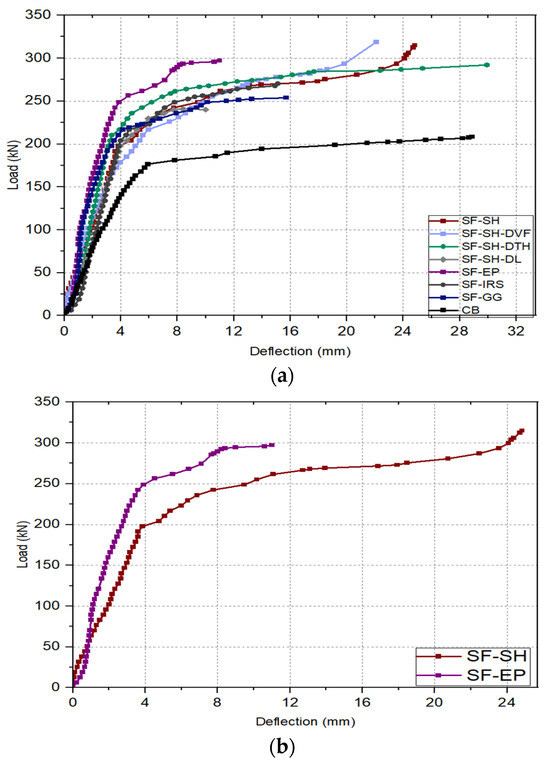
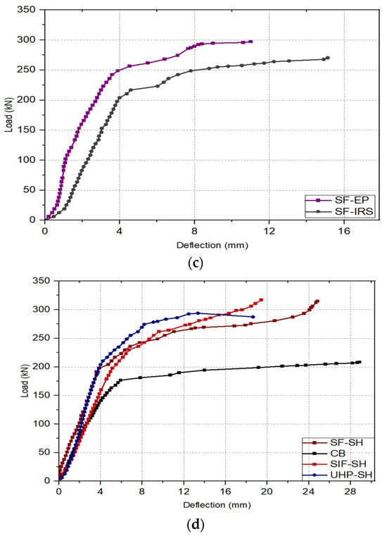
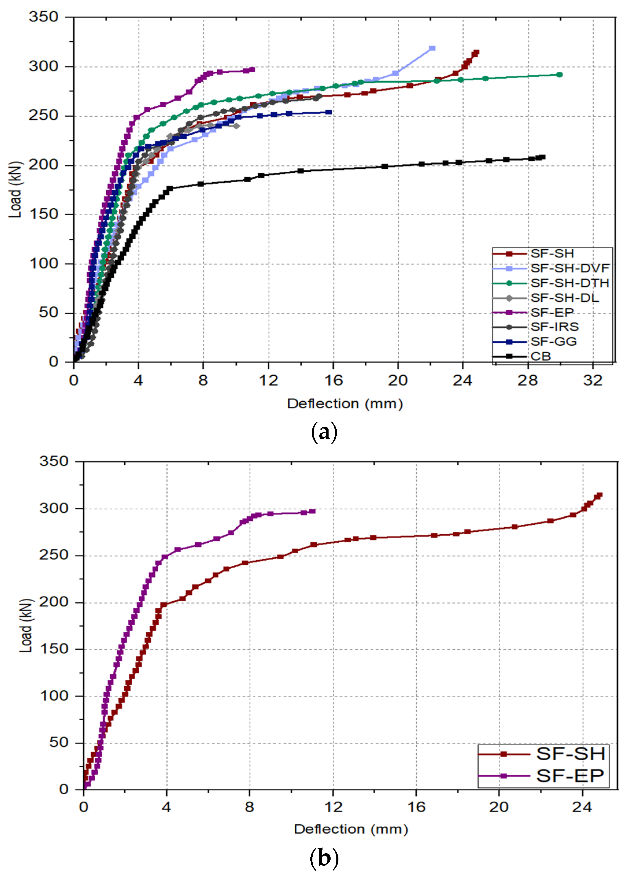
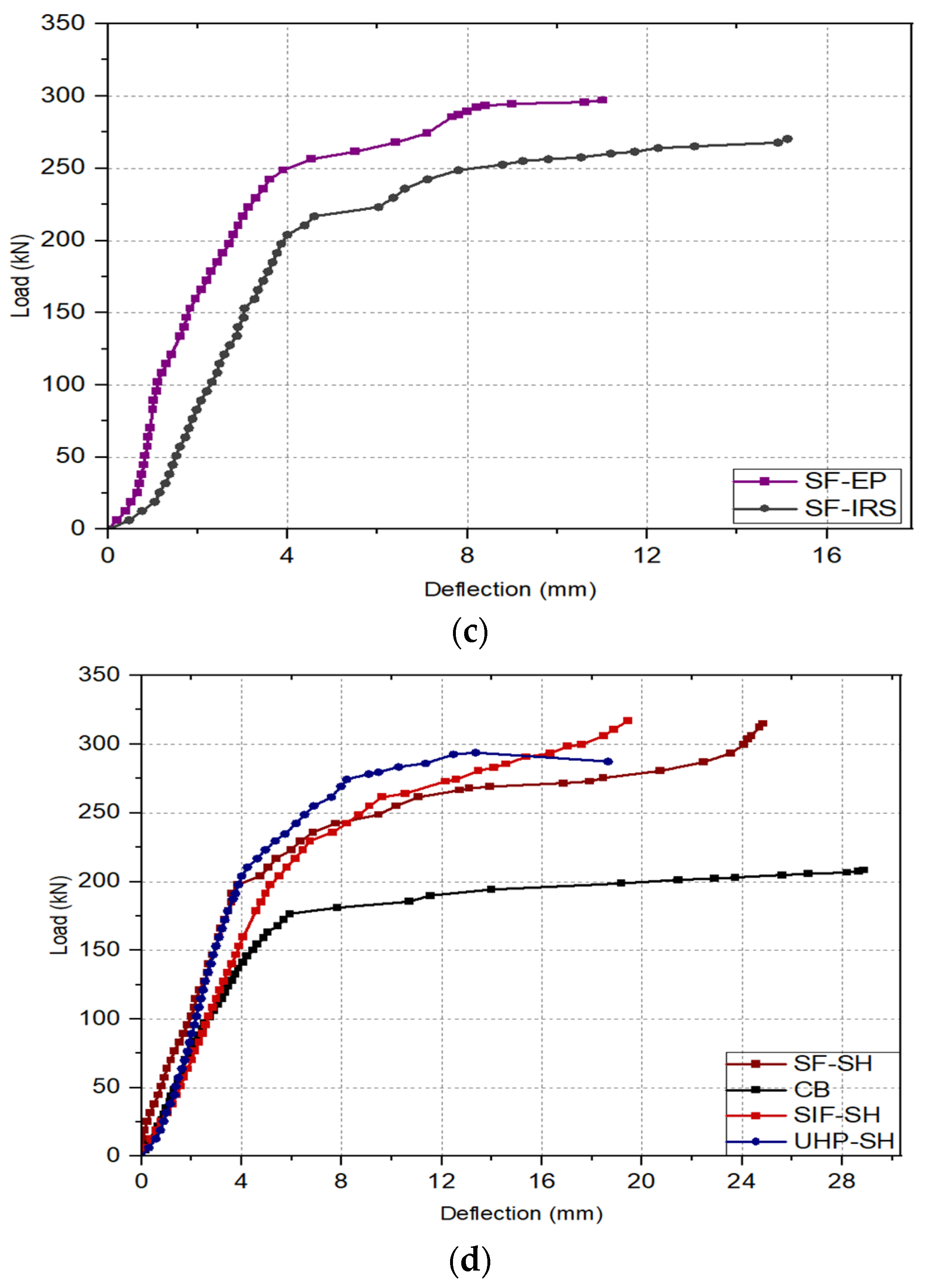
Figure 19 shows the load–deflection curves for the tested continuous beams. It is evident from the figure that the strengthened specimens exhibited behavior almost identical to the reference beam but with higher stiffness. As is clear, the slope of the curve was higher than that of the reference beam. This is attributed to the stiffness of the strengthening plates and their inclusion of steel fibers, which increases the modulus of elasticity. Consequently, this limits the expansion and propagation of cracks, in addition to increasing the bending moment of inertia resulting from the composite behavior of these plates with the beam. Under high loads and after the appearance of several cracks, a decrease in ductility was observed, as the load–deflection curve shows that most beams experienced an increase in deflection with a slight change in load. Beam (SF-SH-DTH) showed the highest ductility from the start of loading. Also it can be noted that in all results, the relationship was linear from the start of loading until the appearance of the first crack.
Figure 19.
Load–deflection curves of continuous beams. (a) Compartion with CB, (b) Type of bonding, (c) Bonding teqniques, and (d) Concrete typ.
Adding SFRC plates to the beam SF-SH improved its load-bearing capacity, enabling it to withstand a load of 315 kN, which increased by 51.2% compared to the failure load of the reference beam. Modifying certain parameters of this SF-SH sample revealed that increasing the proportion of steel fibers in the SFRC mix of beam SF-SH-DVF led to a significant increase in load-bearing capacity. This is attributed to the increased flexibility of the steel fiber and its ability to limit crack propagation, resulting in a 53% increase in load and a deflection of 22.1 mm. However, reducing the length of the SFRC plate in beam SF-SH-DL resulted in a 15.7% increase in load-bearing capacity, a small increase compared to beam SF-SH. Similarly, the SF-SH-DTH beam failed under a load of 292 kN and experienced a displacement of 29.3 mm, which is less than that sustained by the beam with a thicker SFRC plate (see Figure 19a).
Comparing SF-SH and SF-EP samples shown in Figure 19b, the former demonstrated greater load-bearing capacity thanks to the use of shear connectors, which provided a stronger bond between the SFRC sheet and the beam compared to using epoxy.
Comparing the bonding method in the SF-EP beam with the near-surface bonding method in the SF-IRS beam (see Figure 19c), it was found that using a large strengthening plate and increasing the grooving area in the beam’s concrete casing weakens its strength.
Finally, Figure 19d compares SF-SH, UHP-SH, and SIF-SH, which differ in the type of strengthening concrete type. The use of SIFCON resulted in a 52.5% increase in load-bearing capacity compared to the reference beam, with a maximum deflection of 13.35 mm. This performance is superior to the other two types of concrete.
3.3. Stiffness
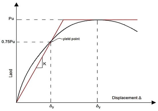
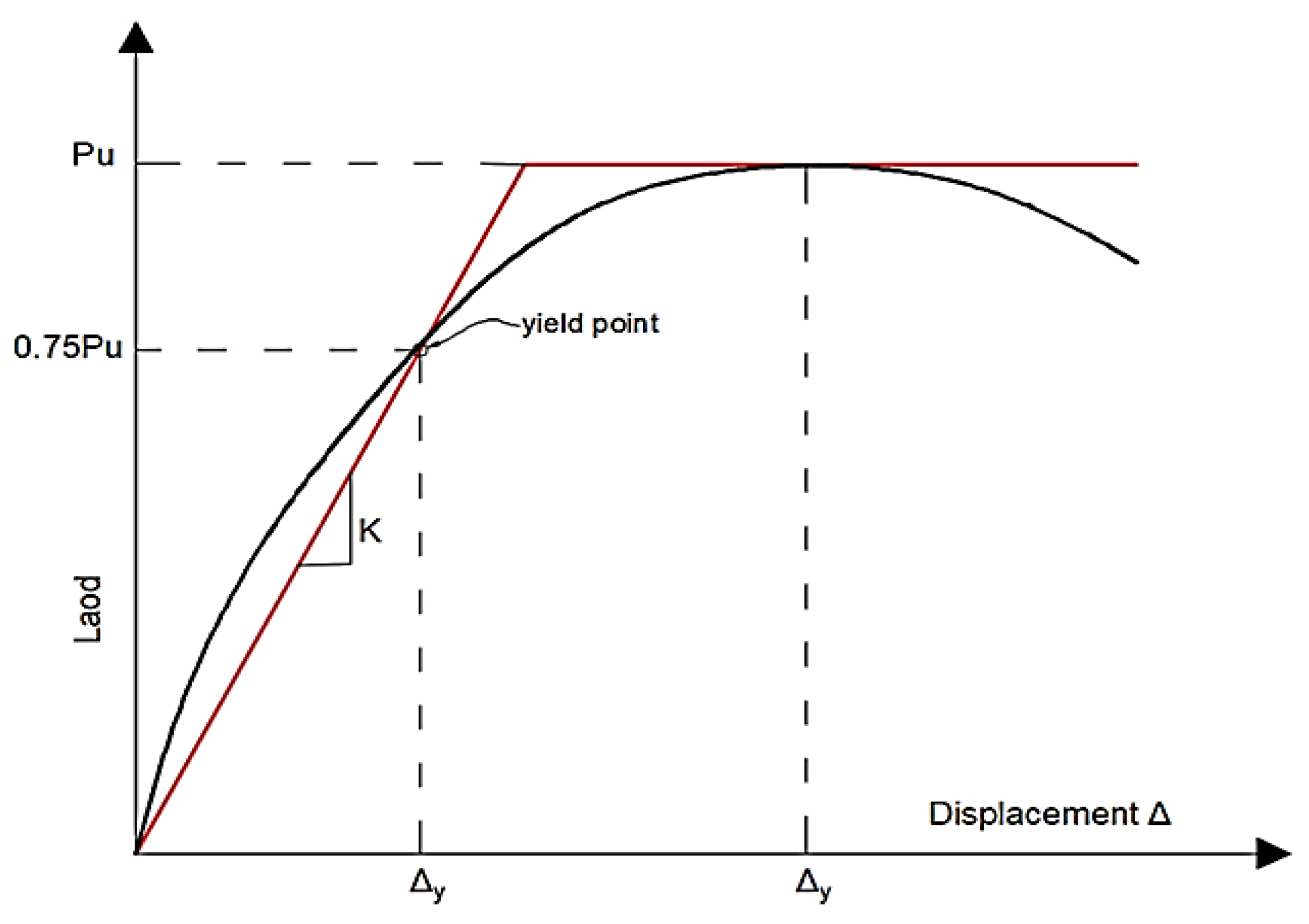
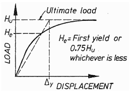
The initial stiffness of all the strengthened beams was calculated and compared to the reference beam. The calculation was based on the load–deflection curves. The stiffness was calculated from the formula (p/∆), where p is 0.75% of the ultimate load and ∆ is the displacement at this load [33], as illustrated in Figure 20.
Figure 20.
Procedures for initial stiffness determination [33].
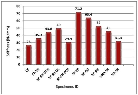
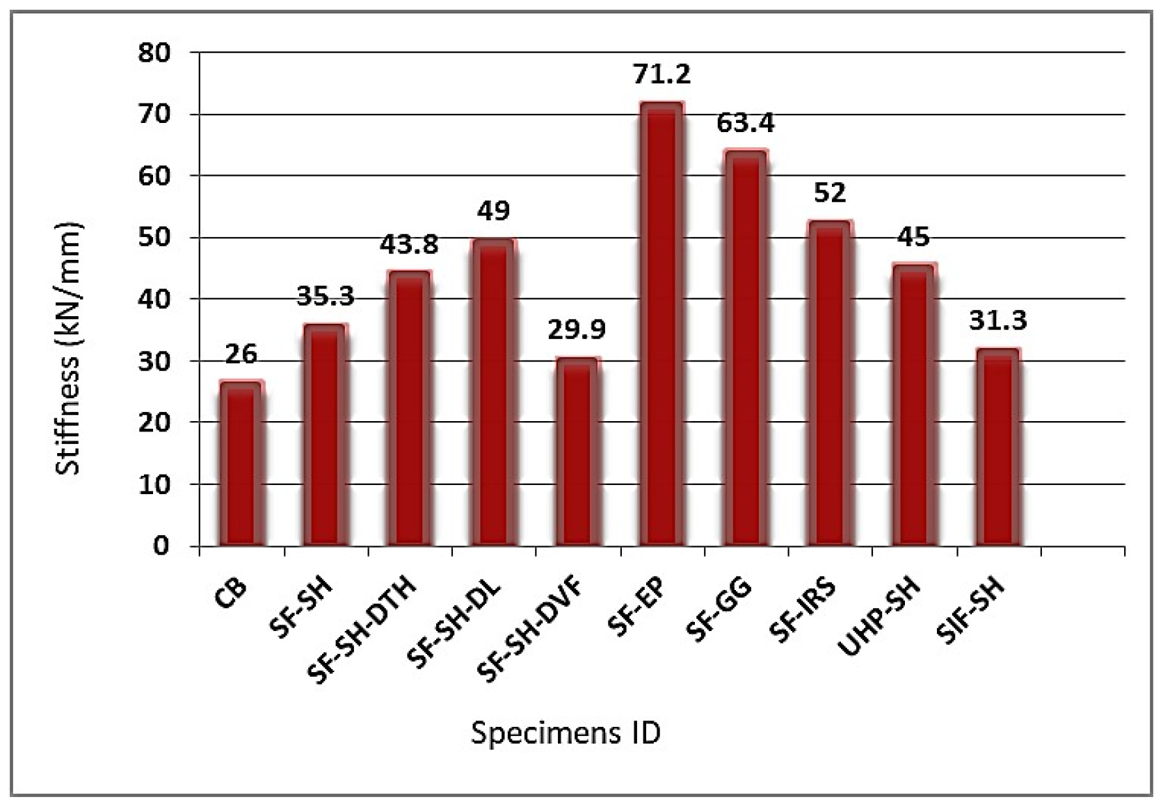
The results shown in Table 7 and Figure 21 indicate that all the samples had higher stiffness than the reference sample. However, the stiffest samples were those in which epoxy was used as a bonding agent, with the increase in stiffness in sample SF-EP being 173.8%. This is attributed to the fact that the uniform and correct distribution of the epoxy created a continuous and homogeneous bond that prevented slippage and increased the initial stiffness [62]. Also, at the same time, sample SF-GG, in which a near-surface bonding method was used, gave a significant stiffness compared to the other beams in which shear connectors were used, with an increase of 143.8% compared to the reference beam, due to the increased fixing.
Table 7.
Test results and observations.
Figure 21.
Initial stiffness results.
3.4. Ductility
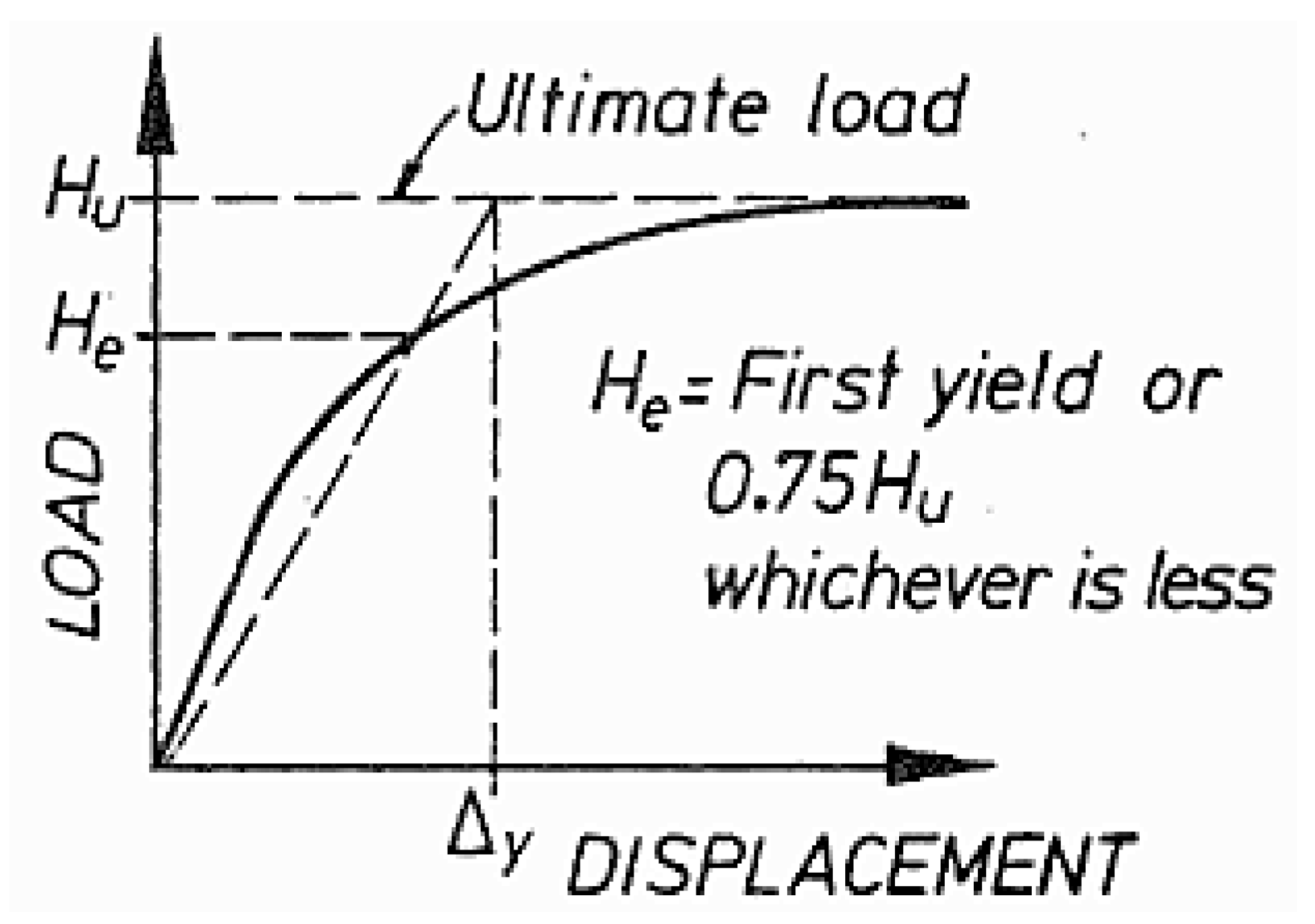
The ability of a material to withstand inelastic deformation before reaching its ultimate strength is known as ductility. The ductility index is defined as the ratio between the ultimate displacement and the yield displacement, calculated as shown in Figure 22 [63].
Figure 22.
Procedures of ductility index determination [62].
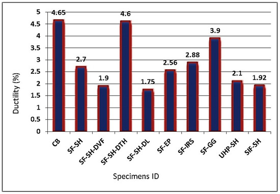
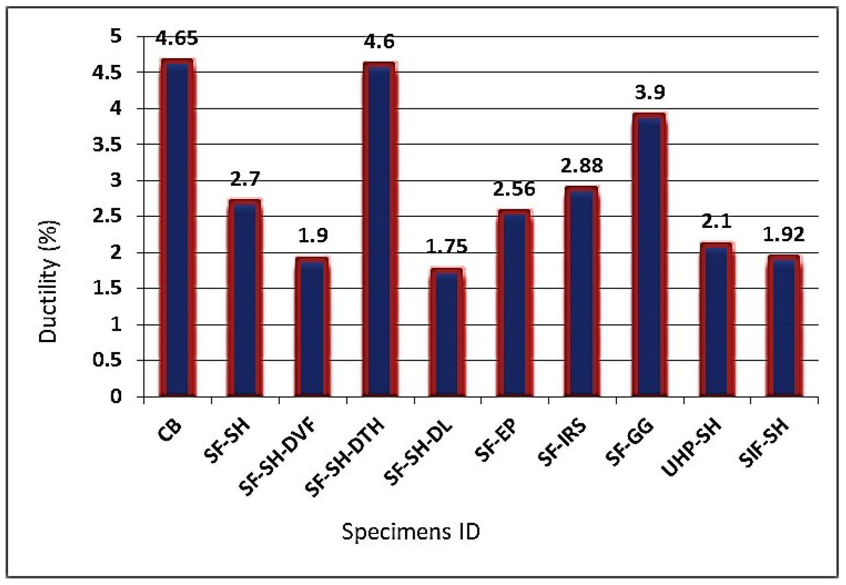
Figure 23 and Table 7 show the ductility index values for the studied specimens. The ductility index for all samples was lower than that of the reference beam; this is due to the appearance of multiple and widespread cracks in the CB, which led to high deflection at maximum load, thus increasing the ductility index.
Figure 23.
Experimental ductility index results.
Furthermore, the use of strengthening plates increased the load-bearing capacity and reduced the number of cracks, leading to less deformation. The lowest ductility index was recorded for beam SF-SH-DL, which suddenly failed due to SFRC breakage and the appearance of large cracks. Beam SF-SH-DTH, on the other hand, had a high ductility index compared to the other strengthened beams due to the large displacement at failure resulting from the reduced thickness of the SFRC layer and its breakage in the positive and negative moment zones.
4. Conclusions
This paper discusses a practical study investigating the flexural behavior of continuous beams strengthened with more than one type of concrete, examining different parameters and various fixing methods.
The study’s findings can be summarized as follows:
- The study verified the effectiveness of using the strengthening techniques in improving the flexural strength of the beams by 15.7% to 53% and their initial stiffness by 15% to 173.8%. In addition to delaying cracking and reducing its propagation.
- In all beams where shear connectors were used, the strengthening plates fractured at the bolted location. In contrast, when epoxy was used, plate cracks continued with the cracks in the beam due to the full bond that made it function as a single element. Whether epoxy or a shear connector was used, there was no slippage or debonding at the connection surface.
- The flexural behavior and flexibility of the beams were improved by increasing the percentage of steel fibers in the SFRC mixture, but at the same time small cracks appeared in the SFRC plate as a result of the mixture inhomogeneity that occurred due to this increment.
- Although the beam’s flexural strength is improved by reducing the SFRC plate length, the effect is still 23.5% less than that of a beam with a longer strengthening plate.
- The improvement in the load-bearing capacity was decreased by reducing the thickness of the SFRC plate from 30 mm to 20 mm, but the flexibility was increased as the SFRC plate was found to bend more with the beam than the others.
- Using the near-surface method resulted in a good improvement in bonding, providing high ductility and reducing slippage and displacement. However, grooving the concrete cover resulted in lower load-bearing capacity compared to other strengthened beams.
- The results show that when using NSM, it is better to use the epoxy bonding rather than the shear connector.
- In this study, three different types of concrete were used as strengthening plates. According to the results, SIFCON was the most effective in terms of increasing the load-bearing capacity of the beams. Nonetheless, this rise was minimal, hardly surpassing 1% in comparison with SFRC.
- The results showed that the reference beam had the highest ductility index due to the large number of cracks, which increased the ultimate deflection, in contrast to the strengthened beams, where the strengthening plates reduced the cracks and controlled their spread.
- Based on the results of the stiffness, the beams where epoxy was used had the highest values due to the increased and more consistent bonding, resulting in a higher initial stiffness than the others. This increase was also observed in the beam where the NSM with shear connectors was used, as the grooves provided greater stability.
Even though this study has attempted to cover several aspects, further research is still needed on the flexural behavior of strengthened continuous beams under different parameters, such as varying the length and thickness of the strengthening plate to determine the optimal one. The effects of the strengthening concrete types when used in situ pouring are also warranted. Furthermore, the effects of the connection system, the distribution of shear connectors, and the number of bolts are recommended for further investigation.
Author Contributions
M.S.Z. and A.Z.H.: experimental work. Z.A.K.A. and H.S.M.: conceptualization, method development, and writing and editing. All authors have read and agreed to the published version of the manuscript.
Funding
This research received no external funding.
Data Availability Statement
The original contributions presented in this study are included in the article. Further inquiries can be directed to the corresponding author.
Conflicts of Interest
The authors declare no conflicts of interest.
References
- Zewair, M.S.; Hamoodi, A.Z.; Malik, H.S.; Naser, K.Z. Shear Strengthening of RC T-Beams Using Externally Bonded UHPC Composite Layers with Steel Plates and Geotextiles. J. Compos. Sci. 2026, 10, 357. [Google Scholar] [CrossRef] [Scilit]
- Al-Osta, M.A.; Isa, M.; Baluch, M.; Rahman, M. Flexural behavior of reinforced concrete beams strengthened with ultra-high performance fiber reinforced concrete. Constr. Build. Mater. 2017, 134, 279–296. [Google Scholar] [CrossRef] [Scilit]
- Mohammed, T.J.; Abu Bakar, B.; Bunnori, N.M. Torsional improvement of reinforced concrete beams using ultra high-performance fiber reinforced concrete (UHPFC) jackets—Experimental study. Constr. Build. Mater. 2016, 106, 533–542. [Google Scholar] [CrossRef] [Scilit]
- Zanotti, C.; Banthia, N.; Plizzari, G. A study of some factors affecting bond in cementitious fiber reinforced repairs. Cem. Concr. Res. 2014, 63, 117–126. [Google Scholar] [CrossRef] [Scilit]
- Denarie, E.; Brühwiler, E. Structural rehabilitations with ultra-high performance fibre reinforced concretes. Int. J. Restor. Build. Monum. 2006, 12, 453–467. [Google Scholar] [CrossRef] [Scilit]
- Elsanadedy Hussein, M.; Husain, A.; Almusallam, T.H.; Al-Salloum, Y.A. Organic versus inorganic matrix composites for bond-critical strengthening applications of RC structures—State-of-the-art review. Compos. Part B Eng. 2019, 174, 106947. [Google Scholar] [CrossRef] [Scilit]
- Pierre, R.; Marcel, C. Composition of reactive powder concretes. Cem. Concr. Res. 1995, 25, 1501–1511. [Google Scholar] [CrossRef] [Scilit]
- Weina, M.; Henri, K.K. Improving flexural performance of ultra-high-performance concrete by rheology control of suspending mortar. Compos. Part B Eng. 2017, 117, 26–34. [Google Scholar] [CrossRef] [Scilit]
- Zemei, W.; Caijun, S.; Henri, K.K. Investigation of mechanical properties and shrinkage of ultra-high performance concrete: Influence of steel fiber content and shape. Compos. Part B Eng. 2019, 174, 107021. [Google Scholar] [CrossRef] [Scilit]
- Chung-Chan, H.; Lee, H.-S.; Chan, S.N. Tension-stiffening effect in steel-reinforced UHPC composites: Constitutive model and effects of steel fibers, loading patterns, and rebar sizes. Compos. Part B Eng. 2019, 158, 269–278. [Google Scholar] [CrossRef] [Scilit]
- Graybeal, B. Material Property Characterization of Ultra-High Performance Concrete; Rep. No. FHWA-HRT-06-103; Federal Highway Administration: Washington, DC, USA, 2006.
- Booki, C.; Doo-Yeol, Y. Hybrid effect of macro and micro steel fibers on the pullout and tensile behaviors of ultra-high-performance concrete. Compos. Part B Eng. 2019, 162, 344–360. [Google Scholar] [CrossRef] [Scilit]
- Jean-Philippe, C.; Emmanuel, D.; Eugen, B. Transport properties of water and glycol in an ultra-high performance fiber reinforced concrete (UHPFRC) under high tensile deformation. Cem. Concr. Res. 2008, 38, 689–698. [Google Scholar] [CrossRef] [Scilit]
- Graybeal, B.; Tanesi, J. Durability of an ultrahigh-performance concrete. J. Mater. Civ. Eng. 2007, 19, 848–854. [Google Scholar] [CrossRef] [Scilit]
- Rafiee, A. Computer Modeling and Investigation on the Steel Corrosion in Cracked Ultra High Performance Concrete; Structural Materials and Engineering Series No. 21; Kassel University Press GmbH: Kassel, Germany, 2012. [Google Scholar]
- Burkart, I.; Müller, H.S. Creep and shrinkage characteristics of ultra high strength concrete (UHPC). In Proceedings of the Second International Symposium on Ultra High Performance Concrete; Kassel University Press: Kassel, Germany, 2008. [Google Scholar]
- Li, Y.; Caijun, S.; Zemei, W. Mitigation techniques for autogenous shrinkage of ultra-high-performance concrete—A review. Compos. Part B Eng. 2019, 178, 107456. [Google Scholar] [CrossRef] [Scilit]
- Brühwiler, E. Improving safety and durability of civil structures. In Damage Assessment and Reconstruction After War or Natural Disaster; Springer: Dordrecht, The Netherlands, 2009; pp. 63–93. [Google Scholar]
- Zhang, Y.; Zhu, Y.; Yeseta, M.; Meng, D.; Shao, X.; Dang, Q.; Chen, G. Flexural behaviors and capacity prediction on damaged reinforcement concrete (RC) bridge deck strengthened by ultra-high performance concrete (UHPC) layer. Constr. Build. Mater. 2019, 215, 347–359. [Google Scholar] [CrossRef] [Scilit]
- Brühwiler, E.; Denarié, E.; Habel, K. Ultra-high performance fibre reinforced concrete for advanced rehabilitation of bridges, Keep Concrete Attractive. In Proceedings of the Fib Symposium 2005, Budapest, Hungary, 23–25 May 2005; pp. 951–956. [Google Scholar]
- Paschalis, S.A.; Lampropoulos, A.P.; Tsioulou, O. Experimental and numerical study of the performance of ultra high performance fiber reinforced concrete for the flexural strengthening of full scale reinforced concrete members. Constr. Build. Mater. 2018, 186, 351–366. [Google Scholar] [CrossRef] [Scilit]
- Mansour, W.; Sakr, M.; Seleemah, A.; Tayeh, B.A.; Khalifa, T. Development of shear capacity equations for RC beams strengthened with UHPFRC. Comput. Concr. 2021, 27, 473–487. [Google Scholar] [CrossRef]
- Mansour, W.; Sakr, M.A.; Seleemah, A.A.; Tayeh, B.; Khalifa, T. Bond behavior between concrete and prefabricated Ultra High-Performance Fiber-Reinforced Concrete (UHPFRC) plates. Struct. Eng. Mech. 2022, 81, 305–316. [Google Scholar] [CrossRef]
- Abbas, H.M.; Kadhim, M.M.; Jawdhari, A. GFRP-reinforced UHPC overlays for strengthening RC beams in flexure. In Structures; Elsevier: Amsterdam, The Netherlands, 2025; Volume 73, p. 108476. [Google Scholar]
- Zhang, Y.; Li, X.; Zhu, Y.; Shao, X. Experimental study on flexural behavior of damaged reinforced concrete (RC) beam strengthened by toughness-improved ultra-high performance concrete (UHPC) layer. Compos. Part B Eng. 2020, 186, 107834. [Google Scholar] [CrossRef] [Scilit]
- Mirdan, D.; Saleh, A.R. Experimental study of flexural behavior for strengthened RC beams by ultra-high performance concrete UHPC overlay. AIP Conf. Proc. 2024, 3009, 030064. [Google Scholar] [CrossRef] [Scilit]
- Zhu, C.; Du, C.; Qi, Y.; Jiang, Z.; Zhang, Z.; Yang, J.; Cheng, J. Flexural Performance of RC Beams Strengthened with High-Strength Steel Wire Mesh and UHPC. Buildings 2025, 15, 589. [Google Scholar] [CrossRef] [Scilit]
- Luo, J.; Hu, M.; Ren, X.; Zhang, B.; Cao, Q.; Shu, J.; Yang, S. Flexural behavior and crack width predictions of RC beams with different pre-damage degrees strengthened by UHPC. Eng. Struct. 2025, 340, 120742. [Google Scholar] [CrossRef] [Scilit]
- Mario, P.; Sandra, N. Experimental tests on RC beams reinforced with a UHPFRC layer failing in bending and shear. In Proceedings of the HiPerMat 2016: Ultra-High Performance Concrete and High Performance Construction Materials, Kassel, Germany, 9–11 March 2016. [Google Scholar]
- Talayeh, N.; Eugen, B. Rotation capacity and stress redistribution ability of R-UHPFRC-RC composite continuous beams: An experimental investigation. Mater. Struct. 2013, 46, 2013–2028. [Google Scholar] [CrossRef] [Scilit]
- Balla, T.M.; Morthala, R.R.; Prakash, S.S. Enhancing flexural performance of reinforced concrete beams using UHPC overlay and external bonding of CFRP composites. Eng. Struct. 2025, 330, 119951. [Google Scholar] [CrossRef] [Scilit]
- Chen, R.; Zhou, J.; Zhang, Z.; Yu, J.; Wang, Z.; Yang, J.; Zou, Y. Flexural performance of damaged RC beams strengthened with UHPC: Coupling effect of load-induced cracking and chloride corrosion. J. Build. Eng. 2025, 115, 114627. [Google Scholar] [CrossRef] [Scilit]
- Mirdan, D.; Saleh, A.R. Flexural performance of reinforced concrete (RC) beam strengthened by UHPC layer. Case Stud. Constr. Mater. 2022, 17, e01655. [Google Scholar] [CrossRef] [Scilit]
- Feng, F.; Zuanfeng, P.; Hongcai, P. Experimental and theoretical study on flexural performance of concrete beams strengthened by unbonded prestressed ultra-high performance concrete layer. Sci. Rep. 2025, 15, 23146. [Google Scholar] [CrossRef] [Scilit] [PubMed]
- Jabbar, I.Y.; Rasheed, L.S.; Sahib, W.S. The behaviour of reinforced concrete beams stiffened with SIFCON. AIP Conf. Proc. 2024, 3091, 020023. [Google Scholar] [CrossRef] [Scilit]
- Marid, H.; Vahidi, E.K. Experimental study on flexural behavior of reinforced lightweight concrete beams strengthening with a slurry infiltrated fiber concrete (SIFCON). Asian J. Civ. Eng. 2024, 25, 1811–1823. [Google Scholar]
- Taher, H.M.A.M.; Dawood, M.B. Shear strengthening of continuous prestressed concrete beams with precast SIFCON laminates subjected to monotonic and repeated loads. Mater. Today Proc. 2022, 60, 2004–2009. [Google Scholar] [CrossRef] [Scilit]
- Said, A.; Elsayed, M.; Abd El-Azim, A.; Althoey, F.; Tayeh, B.A. Using ultra-high performance fiber reinforced concrete in improvement shear strength of reinforced concrete beams. Case Stud. Constr. Mater. 2022, 16, e01009. [Google Scholar] [CrossRef] [Scilit]
- Imoh, U.U.; Habashneh, M.; Kaine, S.C.; Babafemi, A.J.; Hassan, R.; Movahedi Rad, M. Metakaolin-Enhanced Laterite Rock Aggregate Concrete: Strength Optimization and Sustainable Cement Replacement. Buildings 2025, 15, 4553. [Google Scholar] [CrossRef] [Scilit]
- Imoh, U.U.; Apata, A.C.; Movahedi Rad, M. Performance of Concrete Incorporating Waste Glass Cullet and Snail Shell Powder: Workability and Strength Characteristics. Buildings 2025, 15, 2161. [Google Scholar] [CrossRef] [Scilit]
- Ahmed, F.B.; Biswas, R.K.; Sen, D.; Tasnim, S. Flexural and shear strengthening of reinforced-concrete beams with ultra-high-performance concrete (UHPC). Constr. Mater. 2024, 4, 468–492. [Google Scholar] [CrossRef] [Scilit]
- Lafta, Y.J.; Malik, H.S.; Jassim, M.F. Flexural behavior of RC beams externally reinforced with CFRP composites using various strategies. Open Eng. 2024, 14, 20220492. [Google Scholar] [CrossRef] [Scilit]
- Jassim, M.F.; Lafta, Y.J.; Malik, H.S. Shear Behavior of Reinforced Concrete Beams with Different Arrangements of Externally Bonded Carbon Fiber-Reinforced Polymer. J. Eng. 2023, 2023, 1465410. [Google Scholar] [CrossRef] [Scilit]
- Li, W.; Wang, J.; Xing, X.; Liu, H.; Di, J.; Sun, X.; Qin, F. Investigation of Shear Behavior in High-Strength Bolt Connectors for Steel–Concrete Composite Beams. Materials 2024, 17, 6168. [Google Scholar] [CrossRef] [Scilit] [PubMed]
- Abd El Malik Shehata, I.; da Conceição Domingues Shehata, L.; Wagner Freitas Santos, E.; de Faria Simoes, M.L. Strengthening of reinforced concrete beams in flexure by partial jacketing. Mater. Struct. 2009, 42, 495–504. [Google Scholar]
- ASTM C150/C150M-24; Standard Specification for Portland Cement. ASTM International: West Conshohocken, PA, USA, 2024.
- ASTM C204; Standard Test Methods for Fineness of Hydraulic Cement by Air-Permeability Apparatus. ASTM International: West Conshohocken, PA, USA, 2018.
- ASTM C349; Standard Test Method for Compressive Strength of Hydraulic-Cement Mortars (Using Portions of Prisms Broken in Flexure). ASTM International: West Conshohocken, PA, USA, 2019.
- ASTM C191; Standard Test Methods for Time of Setting of Hydraulic Cement by Vicat Needle. ASTM International: West Conshohocken, PA, USA, 2019.
- ASTM C33/C33M-24a; Standard Specification for Concrete Aggregates. ASTM International: West Conshohocken, PA, USA, 2025.
- ASTM C128-01; Standard Test Method for Density, Relative Density (Specific Gravity), and Absorption. ASTM International: West Conshohocken, PA, USA, 2001.
- ASTM C494; Standard Specification for Chemical Admixtures for Concrete. ASTM International: West Conshohocken, PA, USA, 2019.
- ACI 355.2-04/355.2R-04; Qualification of Post-Installed Mechanical Anchors in Concrete and Commentary. American Concrete Institute: Farmington Hills, MI, USA, 2004.
- ACI 318-14; Building Code Requirements for Structural Concrete: (ACI 318-14); and Commentary (ACI 318R-14). American Concrete Institute: Farmington Hills, MI, USA, 2014.
- Tanarslan, H.M.; Alver, N.; Jahangiri, R.; Yalçınkaya, Ç.; Yazıcı, H. Flexural strengthening of RC beams using UHPFRC laminates: Bonding techniques and rebar addition. Constr. Build. Mater. 2017, 155, 45–55. [Google Scholar] [CrossRef] [Scilit]
- ASTM C39/C39M-24; Standard Test Method for Compressive Strength of Cylindrical Concrete Specimens. ASTM International: West Conshohocken, PA, USA, 2024.
- BS EN 12390-3; Testing Hardened Concrete—Part 3: Compressive Strength of test Specimens. BSI Standards Limited: London, UK, 2019.
- ASTM C143/C143M-20; Standard Test Method for Slump of Hydraulic-Cement Concrete. ASTM International: West Conshohocken, PA, USA, 2020.
- Al-zu’bi, H.; Abdel-Jaber, M.; Katkhuda, H. Flexural Strengthening of Reinforced Concrete Beams with Variable Compressive Strength Using Near-Surface Mounted Carbon-Fiber-Reinforced Polymer Strips [NSM-CFRP]. Fibers 2022, 10, 86. [Google Scholar] [CrossRef] [Scilit]
- Aiswarya, A.P.; Prabhakaran, P. Strengthening of reinforced concrete beams in flexure using near surface mounted steel reinforcement. Int. Res. J. Eng. Technol. 2017, 4, 2280–2285. [Google Scholar]
- Wang, H.; Li, C.; Song, S.; Wang, Y.; Meng, Q.; Li, F. Flexural performance of cracked reinforced concrete beams strengthened with prestressed CFRP sheets under repeated loads. Buildings 2023, 13, 2115. [Google Scholar] [CrossRef] [Scilit]
- Shao, J.; Jiang, H.; Zhang, L.; Huang, W.; Mou, T.; Sun, Y. Experimental study on flexural behavior of bonded steel-concrete composite beams. Sci. Rep. 2025, 15, 11451. [Google Scholar] [CrossRef] [Scilit] [PubMed]
- Park, R. Evaluation of ductility of structures and structural assemblages from laboratory testing. Bull. N. Z. Natl. Soc. Earthq. Eng. 1989, 22, 155–166. [Google Scholar] [CrossRef] [Scilit]

Disclaimer/Publisher’s Note: The statements, opinions and data contained in all publications are solely those of the individual author(s) and contributor(s) and not of MDPI and/or the editor(s). MDPI and/or the editor(s) disclaim responsibility for any injury to people or property resulting from any ideas, methods, instructions or products referred to in the content. |
© 2026 by the authors. Licensee MDPI, Basel, Switzerland. This article is an open access article distributed under the terms and conditions of the Creative Commons Attribution (CC BY) license.