


Highlights
What are the main findings?
- Coupled electrical–thermal methods and implosion dynamics are used to study the direct effects of lightning strikes on an aircraft fuel tank cover.
- The implosion effect alters the damage modes of composite materials induced by Joule heating.
What are the implications of these findings?
- Accurate models for simulating lightning strikes on composite materials contribute to elucidating the actual damage mechanisms.
- The research on lightning strike damage to fuel tanks can enhance the reliability of modern aircraft fuel systems.
Abstract
Fuel vapor can be ignited by lightning through various means, particularly through hot spot formation on fuel tank skins. The wing fuel tank cover and its surrounding outer plates together form part of the aerodynamic shape of an aircraft. The lightning protection design of the fuel system, including wing fuel tank, is of great significance for ensuring the aircraft safety. Based on the Joule heating and implosion effect, the damage response of a composite fuel tank cover subjected to lightning strikes is analyzed in this paper. The adopted method combines electrical–thermal coupling with explicit dynamics analysis. Firstly, a finite element model of the fuel tank cover is established using electrical–thermal coupling elements, and the lightning current impact simulation is carried out under given electrical boundary conditions and thermal boundary conditions. On one hand, the ablation criterion is determined by the Joule heating effect and the sublimation temperature of materials. The thermal damage of composite materials subjected to transient high currents is obtained through transient thermal analysis. On the other hand, special implosion elements are selected according to the temperature distribution obtained from the electrical–thermal coupling analysis. The original composite material model in the implosion region needs to be replaced with a new material model described by the high-explosive material model and the JWL equation of state. The von Mises stress distribution and pressure distribution on the structure after implosion are discussed in detail. The results show that concave pits are formed near the implosion zone. Unlike the thermal damage morphology defined by the ablation criterion, the implosion effect makes the damage distribution deviate from the initial fiber direction of each layer. The implosion dynamic method reveals the internal damage and pit and bulge phenomenon around the lightning attachment area to a certain extent.
1. Introduction
In order to reduce costs and weight, aircraft are increasingly manufactured from electrically resistive composites, rather than conductive metals. Lightning is one of the most destructive forces in nature and poses a serious threat to aircraft. Compared with traditional engineering materials, composites exhibit lower electrical conductivity, and thus are more susceptible to lightning strike damage [1,2]. When an aircraft is struck by lightning, a huge amount of energy is instantaneously injected into composite materials in the form of heat conduction, thermal radiation and electric current conduction. It is difficult for lightning currents to be conducted away quickly in a short period of time, and the currents produce heat due to the resistive losses, a phenomenon referred to as Joule heating [3,4,5]. Joule heating has a significant influence on the mechanical behavior of composite structures, one of which is the implosion effect. The pyrolysis of polymer matrices and the sudden combustion of carbon fibers create a pore gas explosion constrained by the surrounding materials.
The fuel system is a very large system distributed throughout the aircraft. As one of the most critical threats to aircraft flight safety, fuel vapor ignition by lightning can occur through various mechanisms, notably through hot spots on the fuel tank. The fuel vapor may be ignited by lightning when the skin is melted and the fuel vapor is directly exposed to lightning. The aircraft fuel system faces the most serious challenge of fuel vapor ignition [6,7,8]. Lightning strike damage involves accounting for the complex interactions between electrical, thermal, and mechanical phenomena within composite materials. Therefore, it is of great engineering significance to conduct research on lightning strike damage to aircraft composite structures [9,10].
Various experimental studies have been conducted to understand the formation of thermal and mechanical kinds of damage on composites under lightning strikes. Wang et al. [11] conducted artificial lightning strike tests to simulate the real-life conditions, thereby characterizing the damage behavior of carbon fiber reinforced polymer (CFRP) composites through analysis of the lightning process and failure modes. Sun et al. [12,13] experimentally evaluated the lightning damage of CFRP laminates exposed to multiple sequential lightning currents, and developed a multi-factor evaluation method. Boushab et al. [14] experimentally examined the effects of the lightning arc channel on surface damage development on a composite plate, and studied two possible driving mechanisms. Using a high-speed camera, Tian et al. [15] observed the lightning attachment process, and investigated the damage characteristics of the two cases where current injection occurred in the carbon fiber part and the fastener part. Through simulated lightning strike experiments, Lin et al. [16] characterized the lightning strike damage tolerance of CFRP laminates containing conductive nanofillers with varying weight fractions. Through experimental testing, Li et al. [17] investigated the damage behavior of laminated CFRP composites under impulse lightning currents.
Given the benefits of simulations over experimental analysis in terms of the cost and specialist test infrastructure required, simulations have become increasingly important in the analysis of lightning strike damage. Larsson et al. [18] provided both a theoretical analysis and a simulation model of the swept stroke processes, along with corresponding simulation results. Wan et al. [19] investigated the changing characteristics of the electrical potential and pyrolysis degree with time to elucidate the electrical conduction mechanism associated with resin pyrolysis. Featherston et al. [20] introduced a method to evaluate mechanical impulse effects caused by lightning attachment to aircraft structures. Lee et al. [21] proposed a novel approach to predict highly nonlinear, transient multiphysics behavior of carbon/epoxy laminates under simulated lightning currents. Lee et al. [22] presented a novel methodology using equivalent air blast overpressure to predict lightning mechanical damage. Shi et al. [23] developed a damage prediction model of multiphysics coupling, by synthesizing the effects of Joule heating and gas expansion, and by incorporating the conversion efficiency of Joule heat to gas kinetic energy. Wan et al. [24] proposed a lightning damage variable, and developed a pyrolysis-affected damage constitutive model to characterize the damage behavior of CFRP induced by lightning. Shan et al. [25] developed a lightning ablation damage model of composite laminates with multiple fasteners, and analyzed the influence of different fastener installation configurations on the lightning ablation damage.
Preceding articles have focused on lightning damage assessment of composite structures and a review of the physics, numerical approaches and problem formulations for multiphysics analyses for simulating lightning strikes. Significant damage could be observed in low-electrical-conductivity materials, as they absorb substantial electrical energy due to increased Joule heating during lightning strikes. For the aircraft fuel system, the damage response of a composite fuel tank cover subjected to lightning strikes is investigated in this paper. A finite element (FE) model of the fuel tank cover is established by using the electrical–thermal solid element SOLID69 in ANSYS software version 15.0. By applying reasonable boundary conditions, the coupled electrical–thermal analysis under lightning current impact is carried out. Firstly, based on the Joule heating effect, the failure criterion is set as the sublimation temperature of materials, and the temperature distribution of the fuel tank cover after thermal damage is obtained. Secondly, special implosion elements are selected according to the temperature distribution of the composite cover. That is, the explicit dynamic element SOLID164 is used to replace the initially defined electrical–thermal element SOLID69 for implosion analysis. Finally, the mechanical responses such as element failure, the von Mises stress and pressure distribution after lightning-induced implosion are discussed. The research findings provide valuable reference values for lightning protection in fuel systems and the flight safety of aircraft.
2. Fuel Tank Cover Model
2.1. Finite Element Model
Lightning originates from the charged centers of clouds, especially cumulonimbus clouds. When the leaders of opposite charges meet, a conductive path is formed enabling charge transfer and resulting in lightning. In order to satisfy the manufacturing process and maintenance requirements, composite fuel tanks need to retain holes with appropriate access doors. The wing fuel tank cover and the surrounding plates together form part of the aircraft’s aerodynamic shape. Fuel vapor ignition is a hazardous effect brought by lightning, which may result in fuel tank explosions. The explosion of a fuel tank caused by fuel vapor ignition can be prevented through measures such as inerting, sealing, and the elimination of ignition sources.
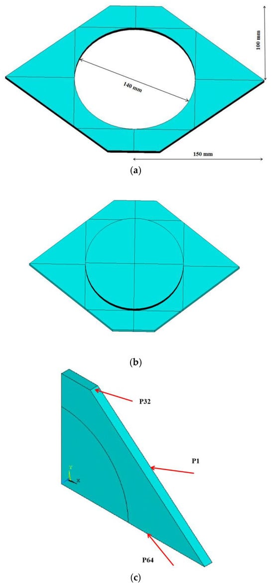
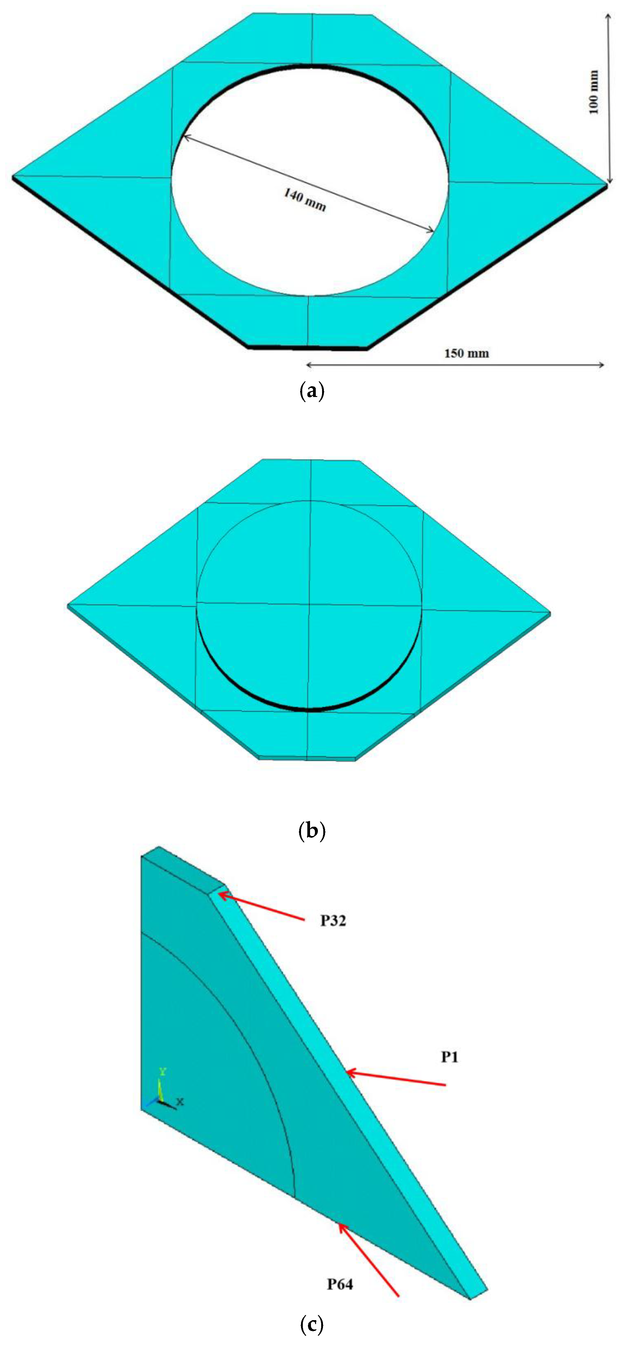
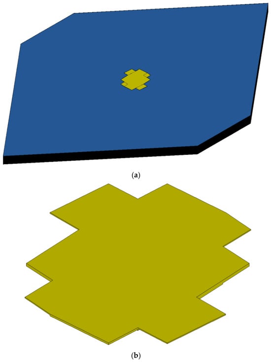
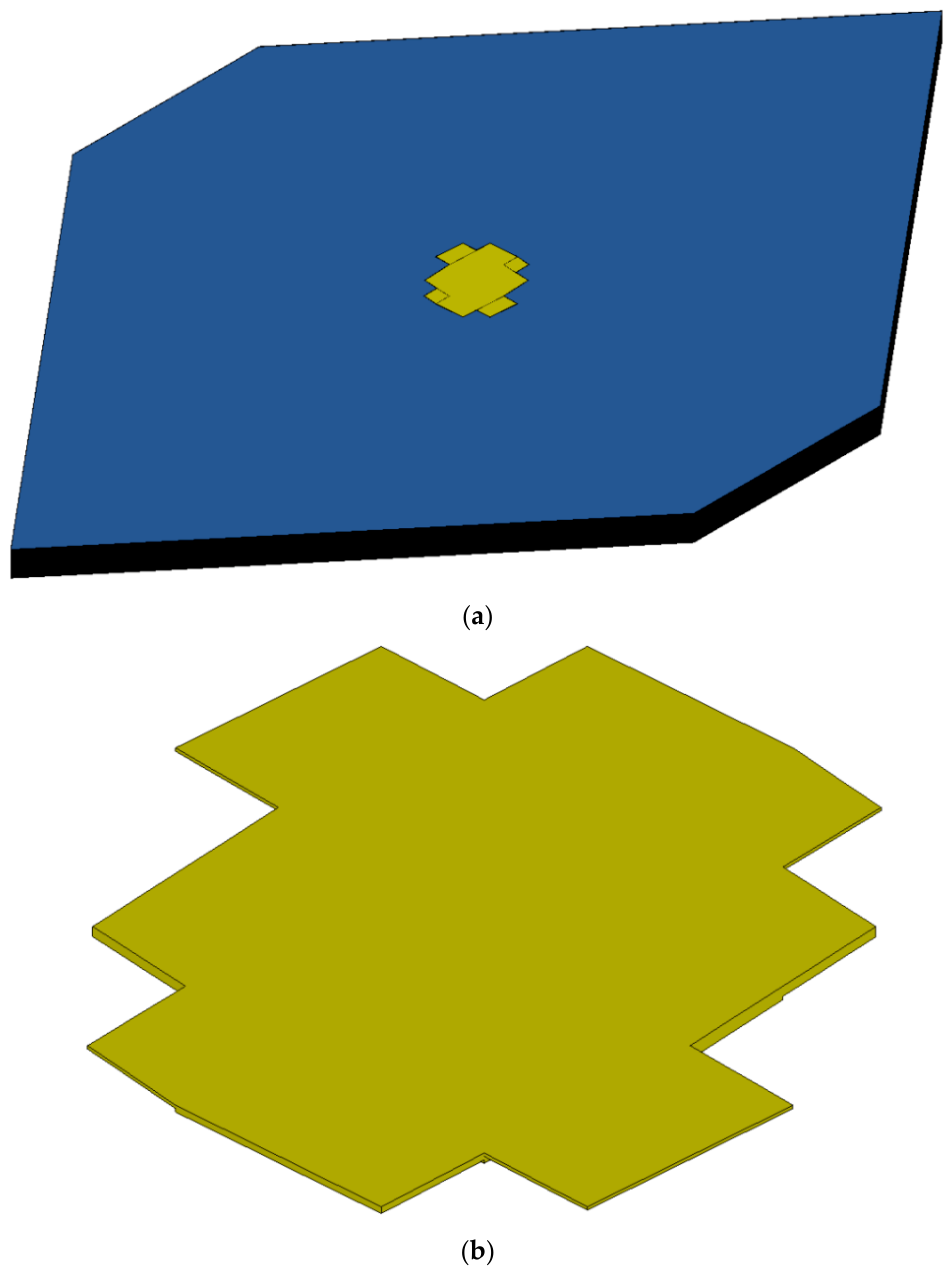
The geometric dimensions of the fuel tank cover structure are shown in Figure 1. The skin is made of composite materials of the IM600/133 type, with a total thickness of 4 mm. The composite skin consists of 32 layers, each with a thickness of 0.125 mm. The radius of the inner hole on the skin is 70 mm, as shown in Figure 1a. The fuel tank cover is also made of composite materials, and the stacking sequence of the composite cover is the same as that of the composite skin. The fuel tank cover has a total of 64 layers, with a single layer thickness of 0.125 mm, as shown in Figure 1b. Stacking sequences in each layer are given in Table 1.
Figure 1.
The whole geometry model of the composite fuel tank cover. (a) Composite fuel tank skin. (b) Composite fuel tank cover. (c) Quarter model of the fuel tank cover.
Table 1.
Stacking sequences in each layer.
In the following sections, the finite element simulation is conducted using a full three-dimensional (3D) model. The 3D finite element model of the aircraft composite fuel tank cover is established by using the electrical–thermal solid element SOLID 69 in ANSYS. The SOLID69 element has eight nodes, each with two degrees of freedom. It is suitable for simulating coupled-field interactions, such as the heat generated by electric currents passing through a resistor. When a current load is applied to the structural surface, the potential distribution and temperature field can be calculated. The model can be discretized into hexahedral elements.
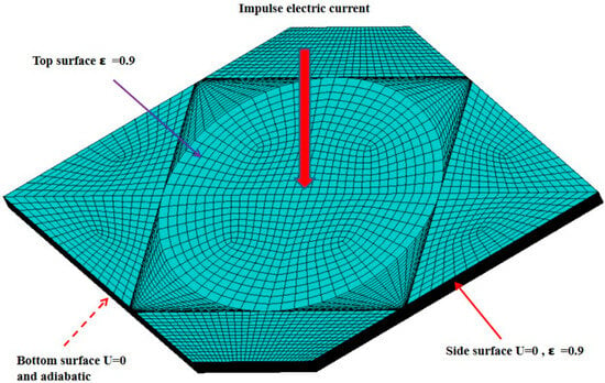
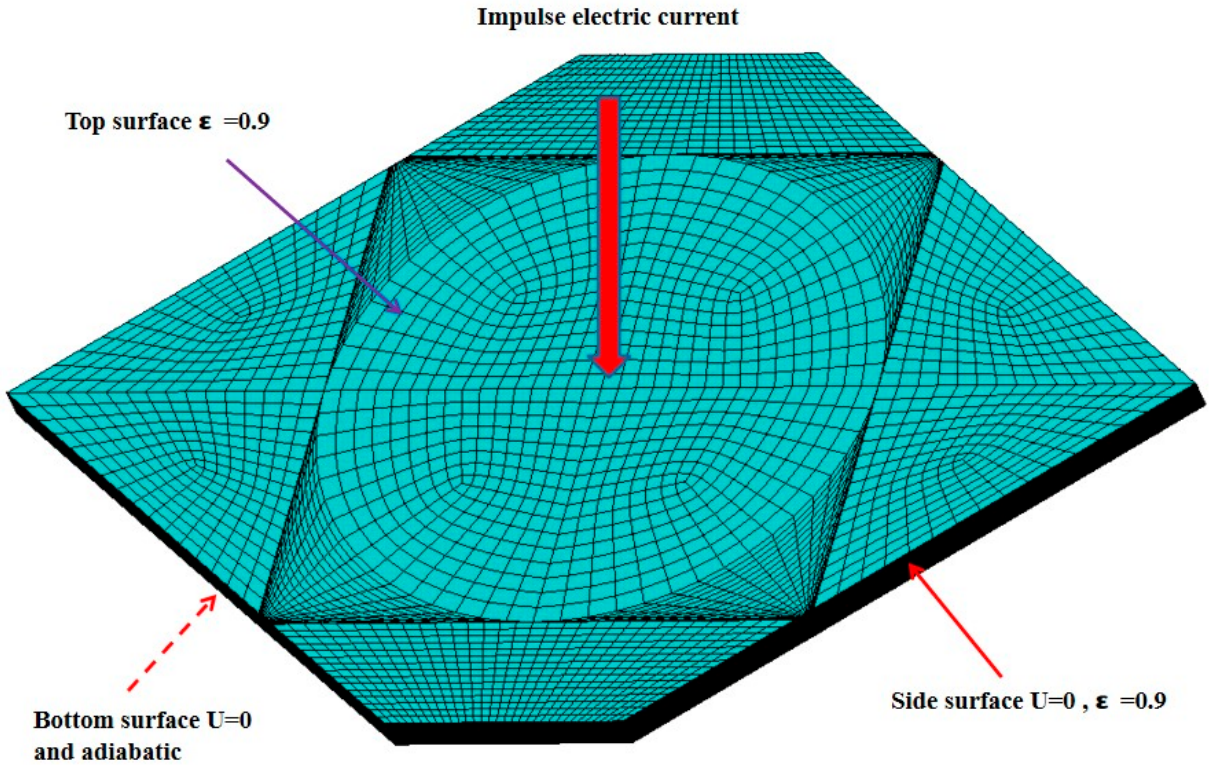
According to actual lightning strike tests of composite materials, the boundary conditions have been determined [26]. The FE model and boundary conditions of the fuel tank cover are shown in Figure 2. The boundary conditions for the cover model under lightning strikes are set as follows.
Figure 2.
Finite element model and boundary conditions of the fuel tank cover.
- (1)
- The electric potential of the bottom surface of the composite cover is set to zero , and the surrounding sides of the fuel tank cover are also set to zero potential.
- (2)
- Due to the short duration of the lightning strike process and the slow temperature transfer, the temperature at the bottom of the fuel tank cover cannot change in time during lightning strikes. The bottom surface of the structure is adiabatic.
- (3)
- The upper surface and surrounding sides of the cover are set as thermal radiation boundaries. The third type of boundary condition for thermal conduction is adopted here, with a thermal radiation coefficient equal to 0.9.
- (4)
- As indicated by the red arrow, lightning current impact simulation is performed on the fuel tank cover under given thermal and electrical boundary conditions. The ambient temperature is set to 25 °C. These conditions and simplifications make it possible to have a model that can be used to understand basic physical effects.
2.2. Material Parameters and Lightning Current Waveforms
When subjected to increasing temperatures between 300 and 500 °C, the composite materials decompose. Above 500 °C the material will be carbonized, and ablation begins when the temperature exceeds 3000 °C. Throughout these phases the material physical properties change with temperature. Finally, the carbon fibers with increased temperature will also be carbonized and eventually ablated at 3316 °C. That is to say, the thermal, electrical and mechanical properties of materials can change with their state and temperature.
The methodologies proposed by Abdelal and Murphy [27] introduce temperature- dependent material properties, including char material properties to simulate material status after decomposition, and gas material properties to simulate material ablation. The thermal, electrical and mechanical properties of the composite material at different temperatures are given in Table 2, Table 3, Table 4 and Table 5.
Table 2.
Temperature-dependent thermal conductivity, specific heat, and density of the composite material.
Table 3.
Temperature-dependent thermal expansion coefficients of the composite material.
Table 4.
Temperature-dependent electric resistances of the composite material.
Table 5.
Temperature-dependent mechanical properties of the composite material.
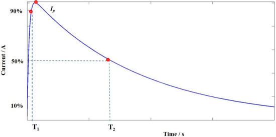
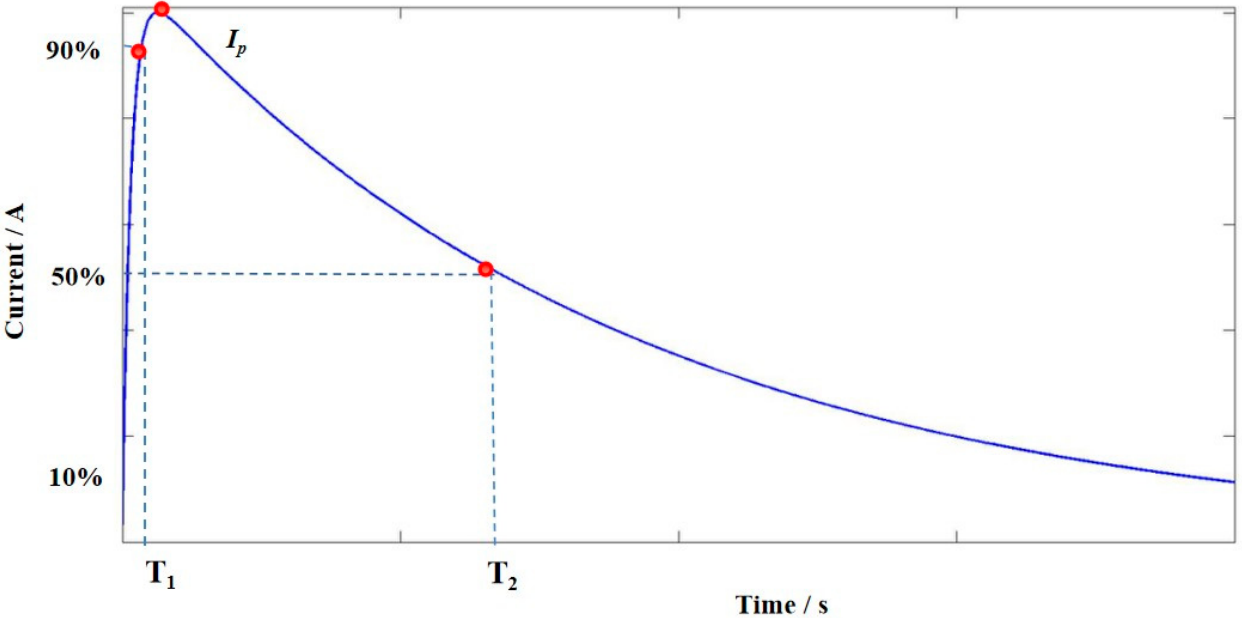
The lightning current waveform adopted in the study is a double exponential waveform, as depicted in Figure 3. The current waveform is expressed in the form:
where is the transient current, represents the current constant, denotes the time, is the reciprocal value of the wave tail time constant, and denotes the reciprocal value of the wave front time constant. Furthermore, a current waveform of double exponential equation can be expressed by the peak current , the front time and the duration time in an actual lightning strike experiment. In addition, denotes the time from 10% to 90% of the maximum current, and represents the time from 10% to 50% through 90% of the maximum current.
Figure 3.
Double exponential impulse current waveform.
In this research, the current duration is , and the calculation process is divided into 12 loading steps. The characteristic parameters are , , . The peak current is , which is sufficient to trigger the implosion effect. And the lightning damage prediction method retains referential significance for higher current levels.
Electrical charge and action integral are the total energy and specific energy of the impulse current, respectively, as follows:
where represents the time-varying electrical current.
3. Implosion Analysis of the Fuel Tank Cover
3.1. Solution Methods
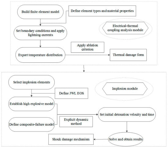
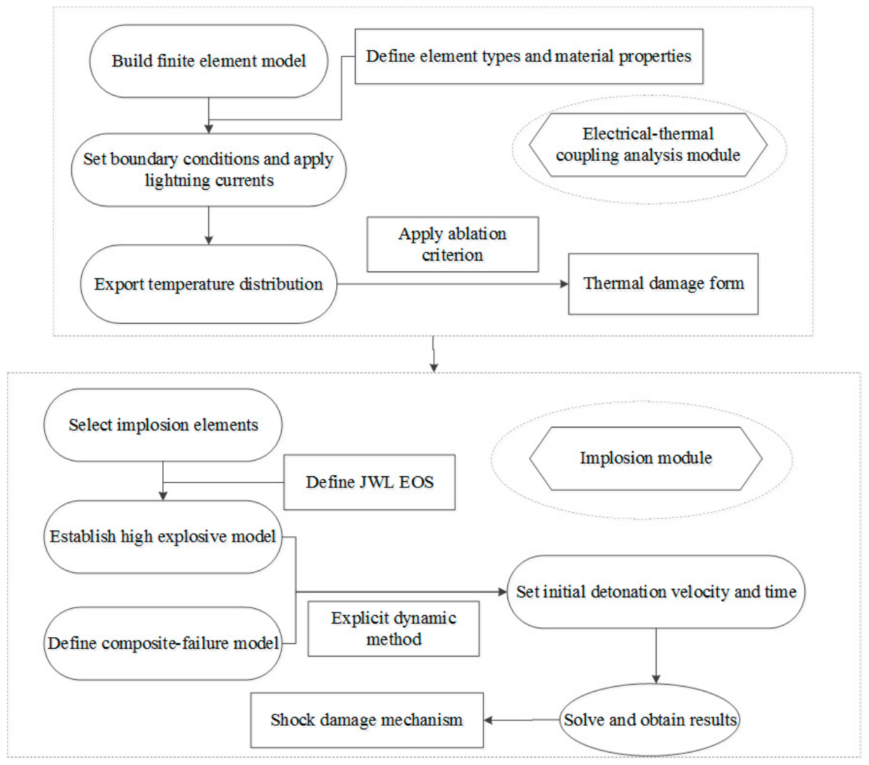
This method primarily consists of two processes, namely the electrical–thermal coupled module and the implosion module. A two-stage analysis flowchart for predicting lightning-induced damage to composite materials is shown in Figure 4. The electrical–thermal coupling analysis is carried out to obtain the temperature distribution in the fuel tank cover. In order to systematically investigate the lightning ablation characteristics of composite materials, the temperature results are processed using two different strategies.
Figure 4.
Two-stage analysis flowchart for lightning damage prediction.
The first strategy is based on electrical–thermal coupling analysis, taking into account the ablation criterion. If the average temperature of elements is lower than the failure temperature, the current load continues to be applied. If the average temperature of elements is greater than the failure temperature, the ablation criterion is adopted and the elements are considered ablated and killed. Simultaneously, according to the calculated transient temperature field, the material physical properties of the elements without ablation are degraded in different temperature ranges.
The other strategy is based on the implosion effect without considering the ablation criterion. Implosion elements are selected according to the temperature distribution in the fuel tank cover. The elements with temperatures exceeding the critical threshold need to be converted into implosion elements in the implosion analysis. The material properties and element types of implosion elements are modified and replaced. The explicit dynamic element SOLID164 is used to substitute the initially defined electrical–thermal coupling element. This explicit dynamic element is suitable for large deformation nonlinear problems such as high-speed impact, collision, and explosion. SOLID164 element type has 8 nodes, each with three degrees of freedom. The initial composite material model in the implosion zone has been replaced with the highly explosive material model described by the Jones–Wilkins–Lee equation of state (JWL EOS). A failure solid model for the rest of the composite materials is defined. The meshing method and element quantities remain the same as those mentioned above. In addition, the surroundings of the fuel tank cover are fixed. The kg-m-s unit system is adopted in the LS-DYNA simulation process. The initial detonation velocity and time of the implosion elements are reasonably set. In this case, the model does not require much computing power.
3.2. Implosion Model Under Lightning Strikes
The goal of the simulation is to study the influence of the implosion effect on the lightning strike damage. The lightning attachment area on composite materials is affected by multiphysics fields, resulting in a rapidly expanding high-temperature zone, known as the implosion zone. Then near the implosion zone, a sharply varying compression zone forms in composite structures under the reverse impulse of vaporization injection. Therefore, it is necessary to develop the equations of state for composite materials under both expansion and compression conditions. For instance, Chen and Huang et al. [28,29] proposed a modified PUFF equation of state with consideration of both nonlinear volume change and anisotropic strength of materials under compression and dilation. They investigated and examined the implosion effect of X-rays on composite materials. However, implosion effects of composite materials under lightning strike conditions are more severe and intense than those under X-rays, and the physical phenomenon is closer to the explosion of explosives. Thus, a high-explosion model of explosives is adopted here, and the JWL EOS is introduced to describe the implosion effects of composite materials subjected to lightning strikes. The constitutive equation for highly explosive material and the JWL equation of state are as follows.
where denotes the pressure of the high-explosive element, is the equation-of-state pressure, represents the internal energy density at the initial volume, and denotes the initial relative volume. is the combustion fraction, which controls the energy release rate during the detonation process. Other mathematical symbols in the above equations represent material parameters, for example and . In addition, and can be written as the following formula.
where represents the current time, is the detonation time for each element, denotes the detonation velocity, is the maximum side area of the element, denotes the element volume, and is the C-J relative volume. For an implosion element, the element stress can be decomposed into volumetric stress and deviatoric stress. In the dynamic finite element method, the JWL equation of state is used to calculate the element pressure .
In regions outside the implosion region, no degradation in the stiffness and strength of the composite material after lightning strikes is considered, and it is assumed that the composite materials retain the initial mechanical properties. However, it is necessary to account for the nonlinear mechanical properties of composite materials under implosion effects, including the elastic–plastic and failure behavior. In this paper, the material type of Mat_Composite_Failure_Solid_Model No. 59 is adopted, which is provided by Keyword User’s Manual of ANSYS/LS-DYNA. The material model No. 59 can characterize the nonlinear mechanical behavior of composite materials under impact and blast loads. It can be defined as follows:
where denotes an ellipsoidal function, and represent tensile and compressive strengths in the fiber direction respectively, and are transverse tensile and compressive strengths, and represent tensile and compressive strengths in the out-of-plane normal direction, denotes shear strength in-plane, and and denote shear strengths in the out-of-plane directions. The yield function can be established using the strength parameters and stress tensor of composite materials. When is greater than zero, elements enter the plastic stage. Subsequently, the elements continue to deform under external loads, and the stiffness of composite materials also decreases. The existing constitutive parameters of explosives are modified here. The characteristic parameters of the high-explosive, JWL EOS and material model No. 59 are given in Table 6.
Table 6.
Characteristic parameters of the high-explosive, JWL EOS and material model No. 59.
For composite elements that have entered the plastic stage, once their equivalent strain reaches or exceeds the maximum strain value, the element is deleted. This means that the composite materials at the location of deleted elements no longer have the ability to continue bearing loads. The maximum equivalent strain for material failure in LS-DYNA can be set in the tab of the keyword MAT_ADD_EROSION. The expression for equivalent strain is defined as follows.
where is the deviator strain component.
4. Results and Discussion
4.1. Electrical–Thermal Coupling Analysis
Lightning strikes are essentially high-amplitude direct-current pulses. CFRP exhibits highly orthotropic electrical resistivity, which increases aircraft vulnerability to lightning strike effects. Lightning strikes on aircraft tend to generate intense coupled multiphysics field effects on the surface of composite structures, which causes the thermal expansion, ablation and vaporization of composites. In view of the complexity of the lightning strike problem, the ablation criterion is usually employed to deal with the temperature distribution of the composite fuel tank cover in the first stage of electrical–thermal coupling analysis. The method takes fiber sublimation and ablation into account when the surface temperature reaches or exceeds the critical threshold. The ablation criterion is incorporated in the simulation process, and ablation elements are defined after calculating the transient temperature field. According to the comparison between the average temperature and the ablation temperature, the conditions for element deletion are determined.
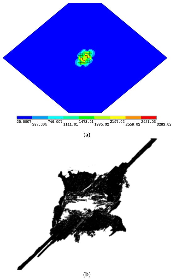
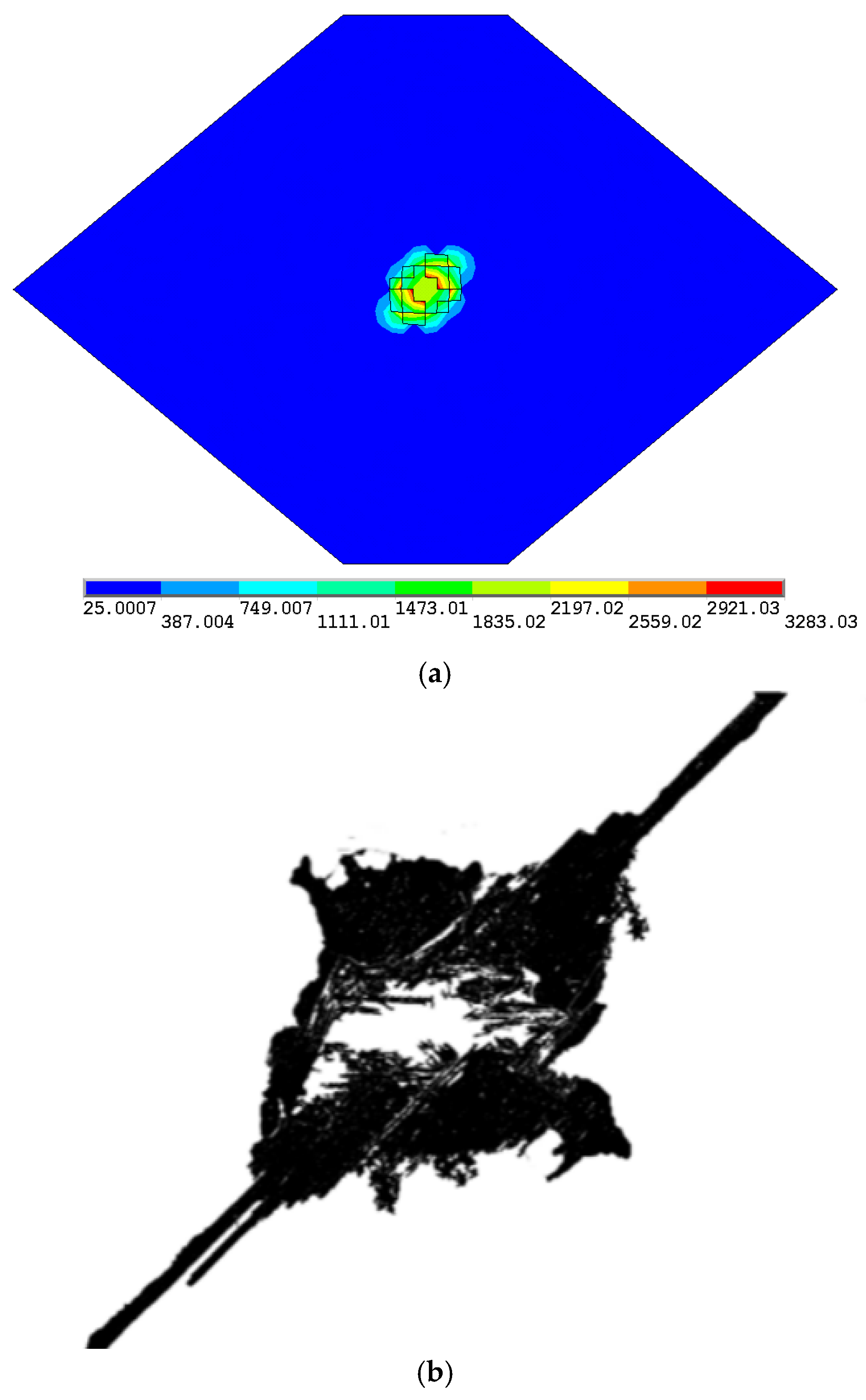
Compared with traditional engineering materials such as titanium alloys and aluminum alloys, composite materials have poor electrical and thermal conductivity. When lightning currents directly attach to the surface of composite structures, it is difficult to conduct lightning currents instantaneously, which can easily lead to the accumulation of charge and energy. As a result, a significant amount of energy is deposited on the surface of the fuel tank cover, causing a sharp rise in the surface temperature of the composite material. The temperature distribution of the fuel tank cover is shown in Figure 5. The shape of the lightning damage area on the aircraft fuel tank cover predicted by the numerical simulation is basically consistent with the published experimental results [30].
Figure 5.
Comparison of simulation results of lightning damage to composite materials with experimental results. (a) Temperature distribution of the fuel tank cover considering ablation (unit: °C). (b) Resin deterioration area obtained by image binarization.
The initial lightning current is applied to the center position of the fuel tank cover. It can be seen that the temperature distribution around the lightning attachment area is similar to an ellipse, with the major axis of the ellipse along the fiber-laying direction of the surface layer. That is to say, the damage morphology is elliptical, and its damage contour is along the direction of the surface fiber layer. A large number of elements have been deleted near the lightning attachment zone. Further research shows that there is a certain temperature increase in the composite fuel tank skin, but the amount of temperature increase is very small. This is because the electrical conductivity and thermal conductivity in the thickness direction are much lower than those in the fiber direction. Therefore, Joule heating generated by lightning currents mainly causes severe thermal damage to the first few layers around the lightning attachment area, and little damage to the other parts. The above example illustrates the influence of the ablation criterion on the simulation results of the temperature distribution.
4.2. Implosion Effect Analysis
The theoretical reason behind this phenomenon is discussed. The gas produced by the pyrolysis of the resin matrix is easily surrounded by the matrix and fibers of the surrounding composite materials. The gas pressure increases sharply in an instant. When the pressure exceeds the constraint strength of the surrounding environment, explosive gas splashing may occur, resulting in a reverse impact effect on composite structures. According to the results of electrical–thermal coupling analysis, the elements whose temperature reaches or exceeds the critical temperature are selected as the implosion elements.
Figure 6 shows a dynamic finite element model for simulating the implosion effect in composite structures caused by lightning strikes. Figure 6b displays an enlarged view of the implosion elements located in the central area of the top surface. The rest are non-implosion elements, and the model No. 59 is used as the material parameter model to describe the nonlinear mechanical behavior of materials. In the thickness direction, these implosion elements are all concentrated in the outermost two layers of the fuel tank cover. The keyword file is modified in LS-PrePost and submitted to the LS-DYNA solver. For example, the maximum failure strain is defined in the keyword file. The failure elements are identified based on the maximum failure strain. If the equivalent strain of an element is greater than the maximum failure strain, the element is considered to have failed and is deleted. For another example, the keyword CONTROL_TERMING is used to set the termination time for explicit dynamics calculations to . Results of the different quantities computed in this model are presented below.
Figure 6.
Finite element model of implosion dynamic analysis induced by lightning. (a) Finite element model of implosion dynamics for the fuel tank cover. (b) The implosion elements.
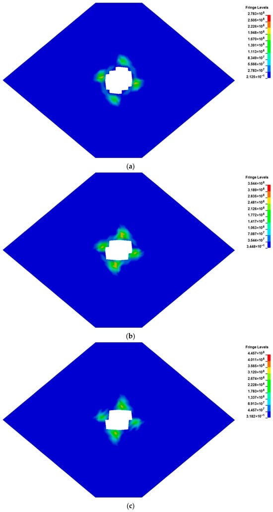
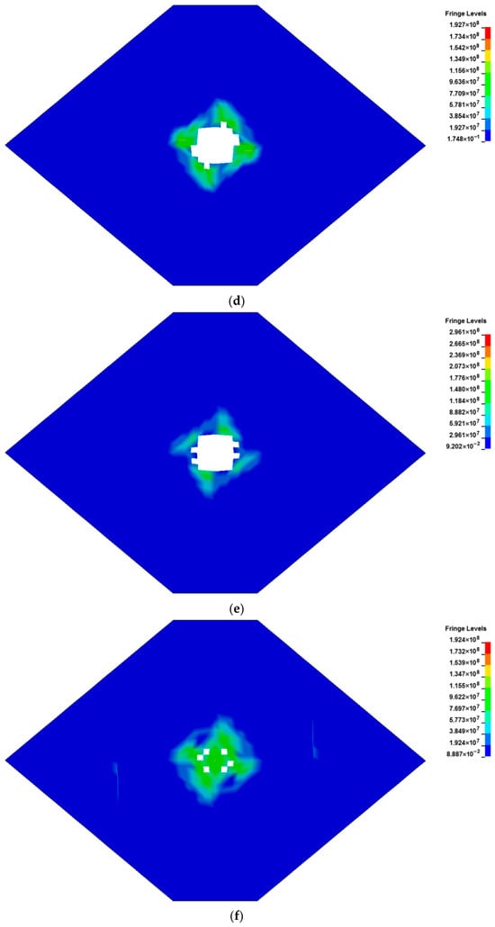
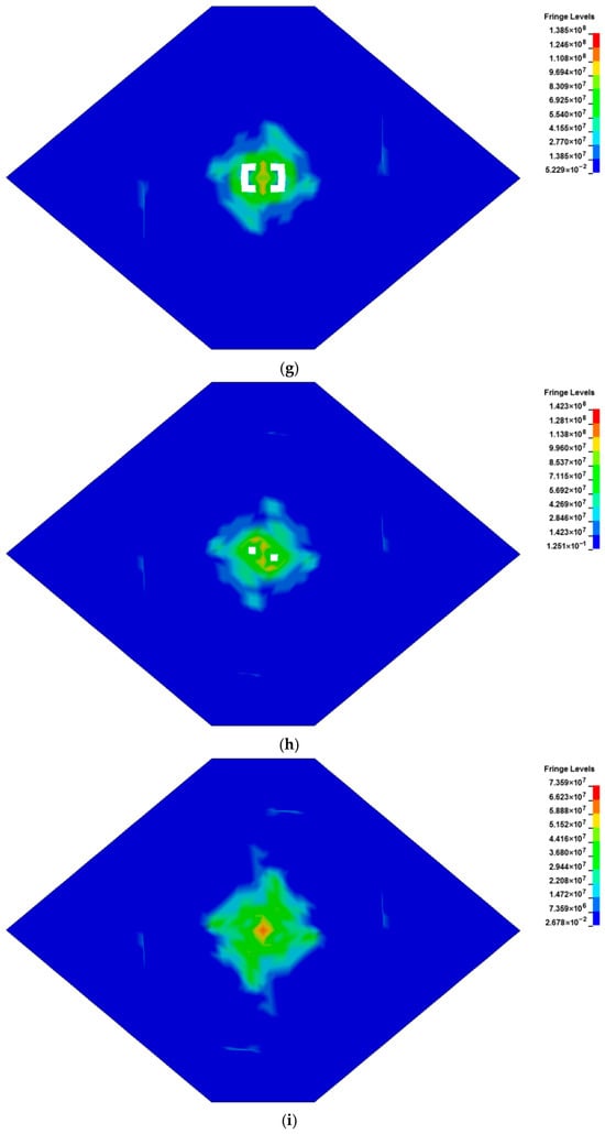
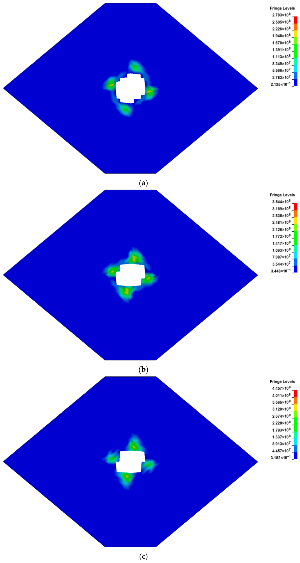
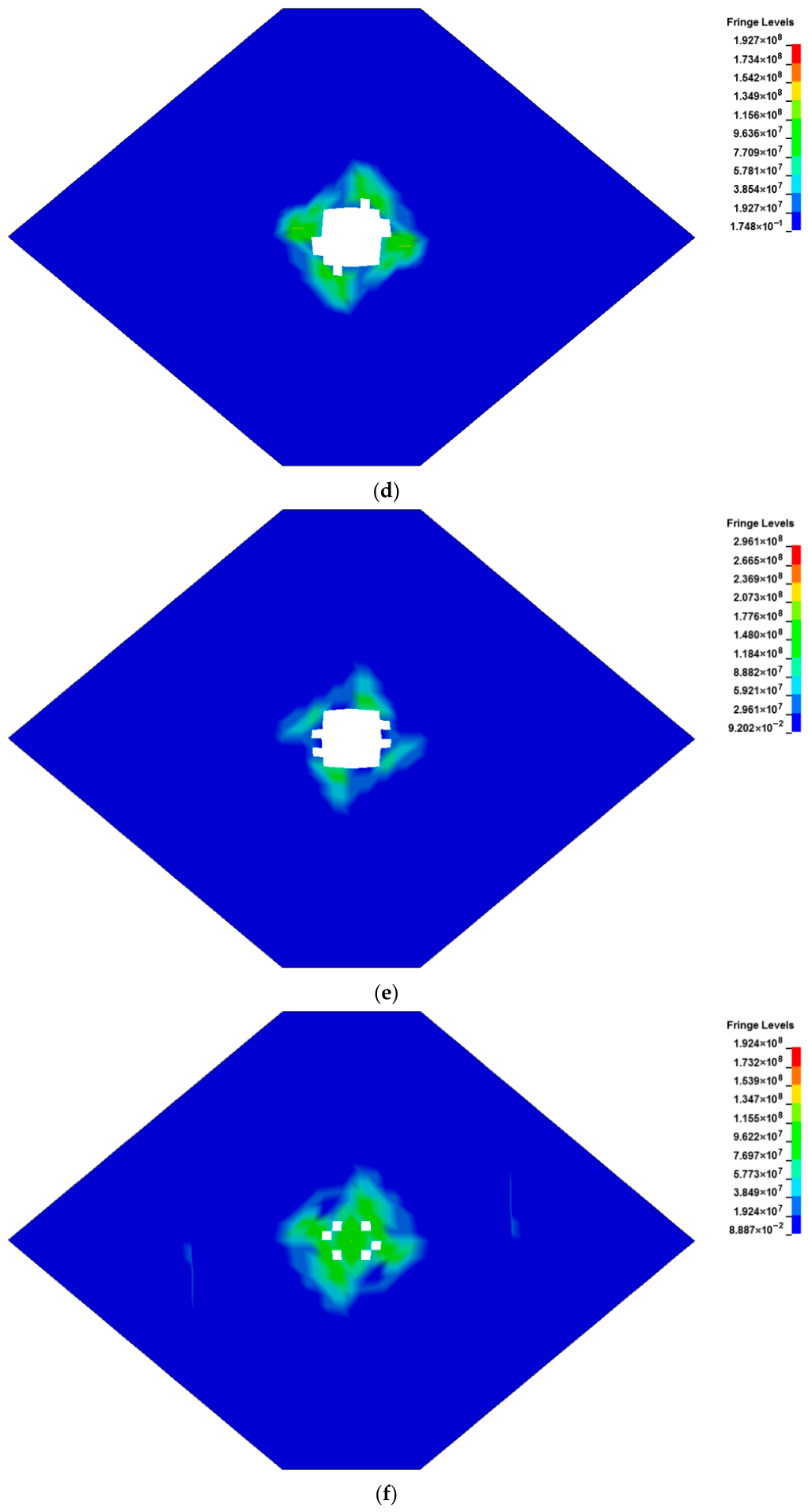
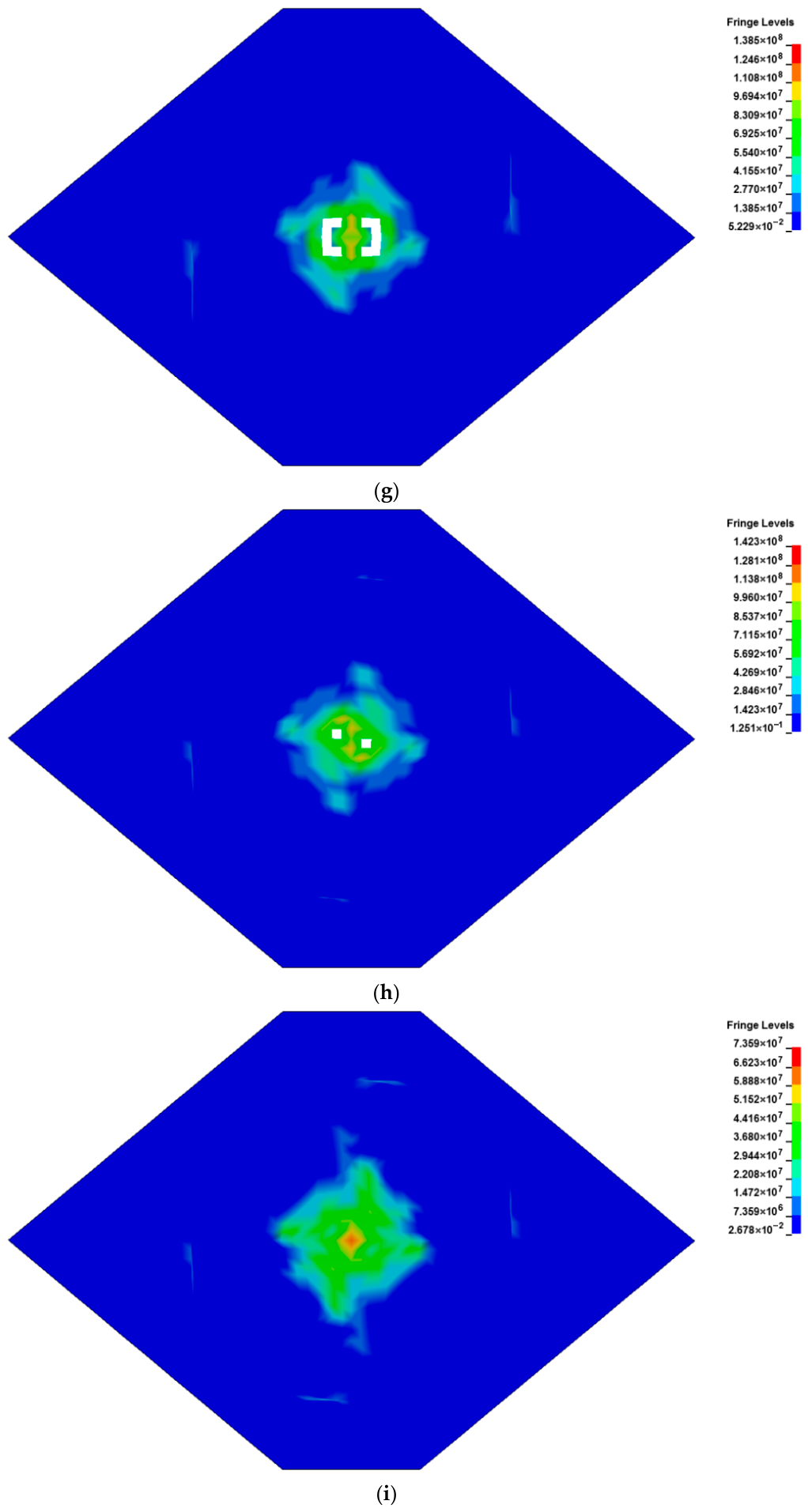
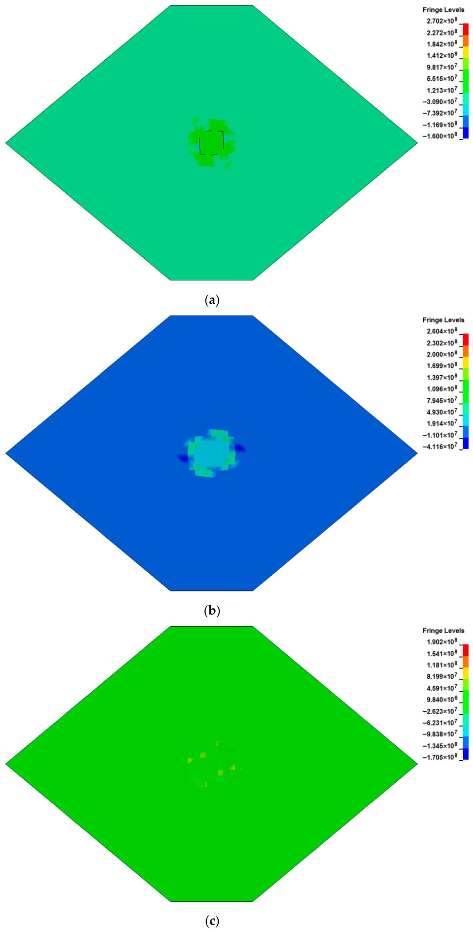
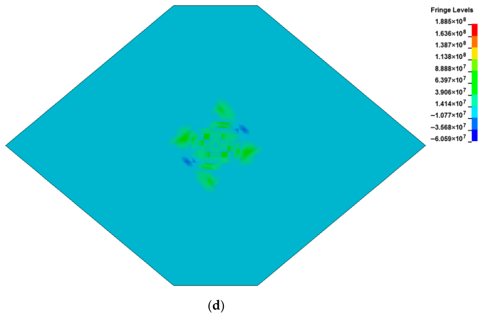
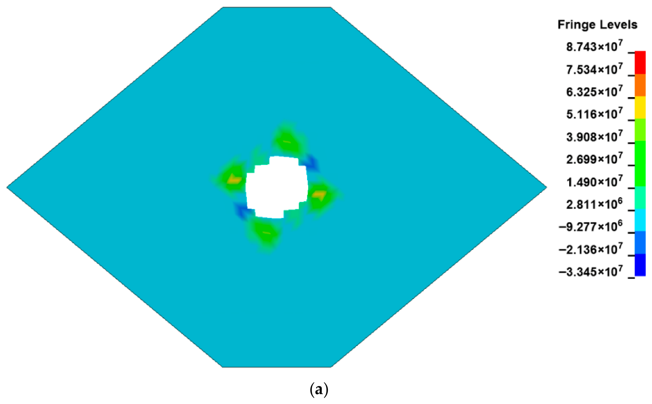
Figure 7 shows the element failure and the contours of von Mises stress in the top nine layers after the implosion at . The damage to composite materials caused by implosion can be observed, and the most severe failure occurs in the first layer. It is worth noting that the contour of von Mises stress deviates from the fiber direction. That is, the damage morphology is significantly different from that caused by Joule heating and ablation criteria shown in Figure 5. From a practical point of view, the two types of damage induced by the implosion effect and electrical–thermal mechanism occur in a coupled manner. The volume fraction of failed elements decreases sequentially from the first layer to the ninth layer. The failure elements in composite materials are mainly concentrated in the center of each layer. However, the distribution of some failed elements in the sixth, seventh, and eighth layers is relatively scattered. Additionally, there are no failed elements in the ninth layer.
Figure 7.
Element deletion and contours of von Mises stress in the nine layers (unit: Pa). (a) Layer 1. (b) Layer 2. (c) Layer 3. (d) Layer 4. (e) Layer 5. (f) Layer 6. (g) Layer 7. (h) Layer 8. (i) Layer 9.
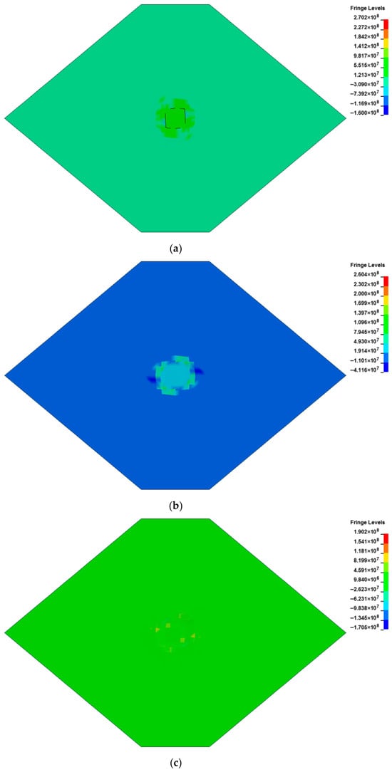
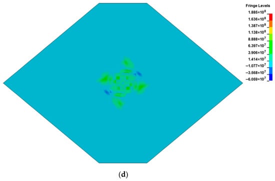
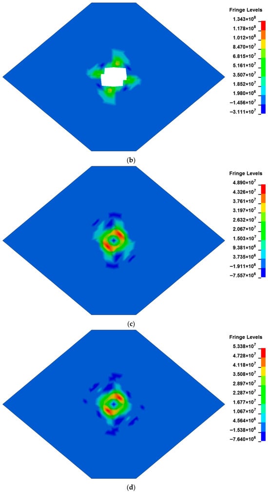
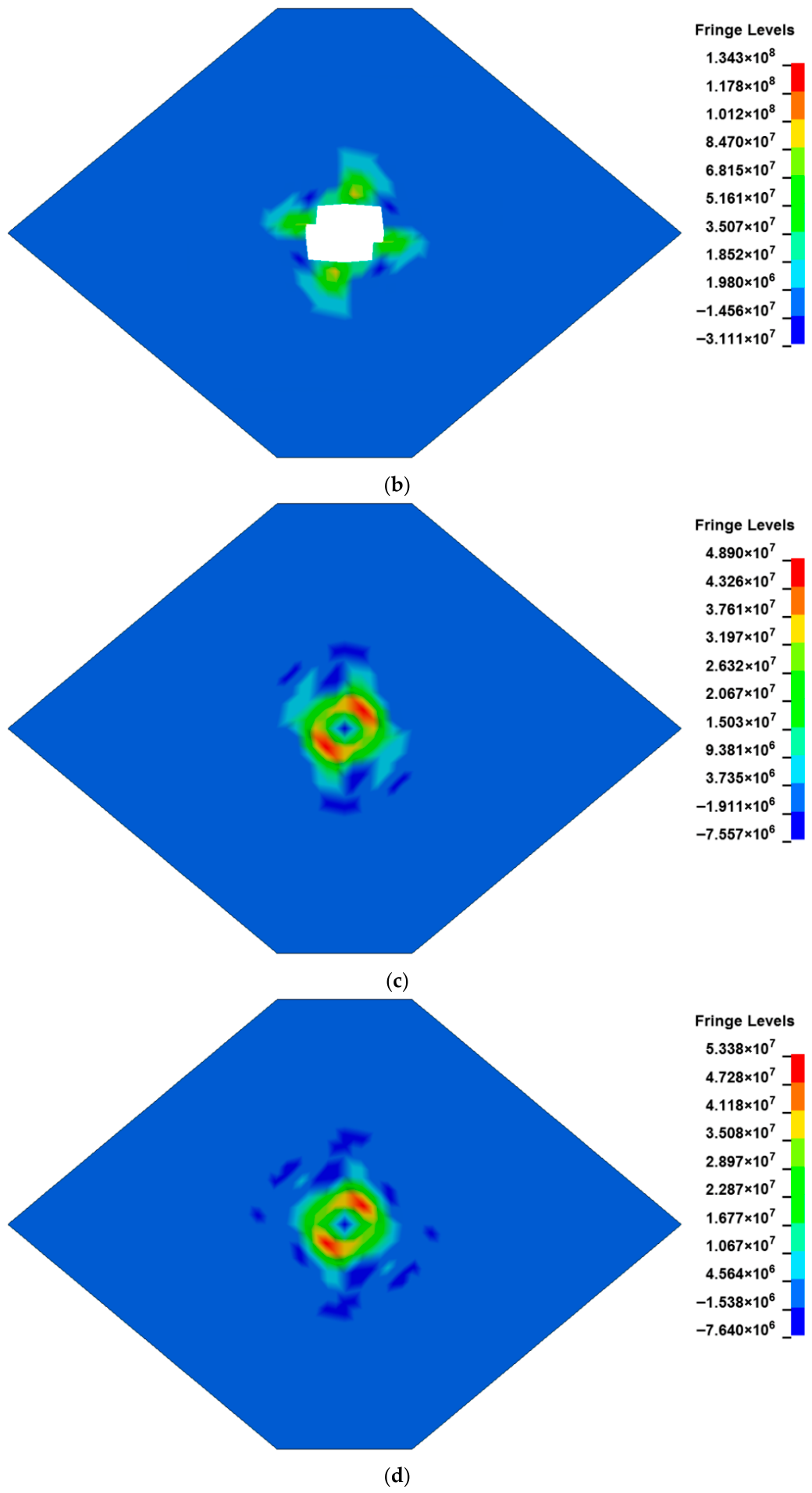
The impact of the implosion effect on the lightning damage to composite materials cannot be neglected. The reason is that the implosion effect tends to cause strong propagation of detonation waves within composite structures. Figure 8 shows the pressure distribution of the fuel tank cover at different times. The maximum pressure occurs in the central region, and it decreases over time. When the time reaches , the implosion effect is completed, and the maximum damage is achieved.
Figure 8.
Pressure contours at different time points (unit: Pa). (a) . (b) . (c) . (d) .
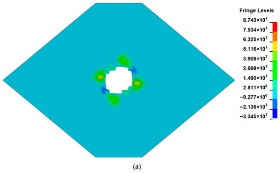
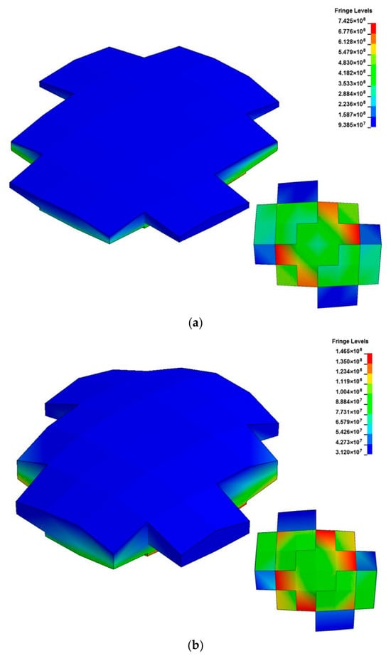
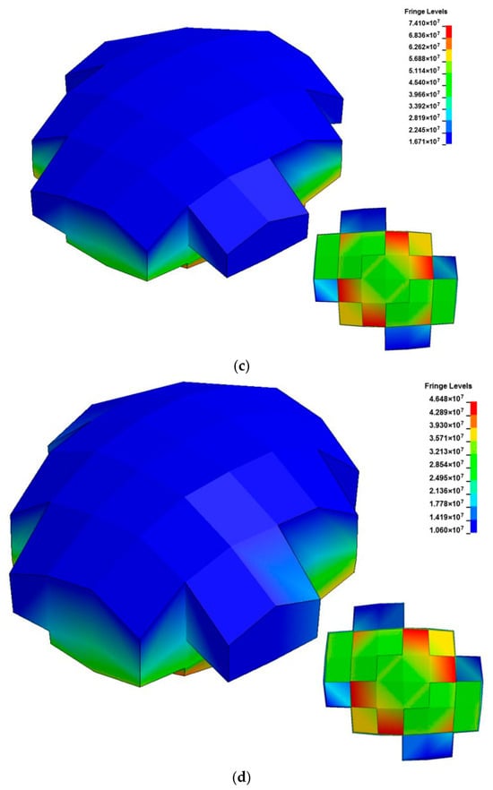
Figure 9 presents the pressure distribution in the top two layers and the middle two layers of the fuel tank cover at . It can be observed that the pressure distribution across the layers is highly irregular. The element deletion phenomenon occurs within the top several layers, and the pressure field gradient between adjacent layers is relatively large. A large pit forms around the implosion area. The farther away from the top layer the explosion occurs, the more isotropic the pressure field in composite materials tends to be. Element deletion also occurs in the thickness direction, which indicates that shock waves may cause some invisible internal damage. The implosion mechanism effectively simulates and presents the internal damage, pits, and bulges around the lightning strike attachment area. The failure mode of the implosion region obtained through numerical simulation shows similarity to the damage caused by actual lightning strikes.
Figure 9.
Element deletion phenomenon and pressure contours in some layers. (a) Upper Layer 1. (b) Upper Layer 2. (c) Middle Layer 31. (d) Middle Layer 32.
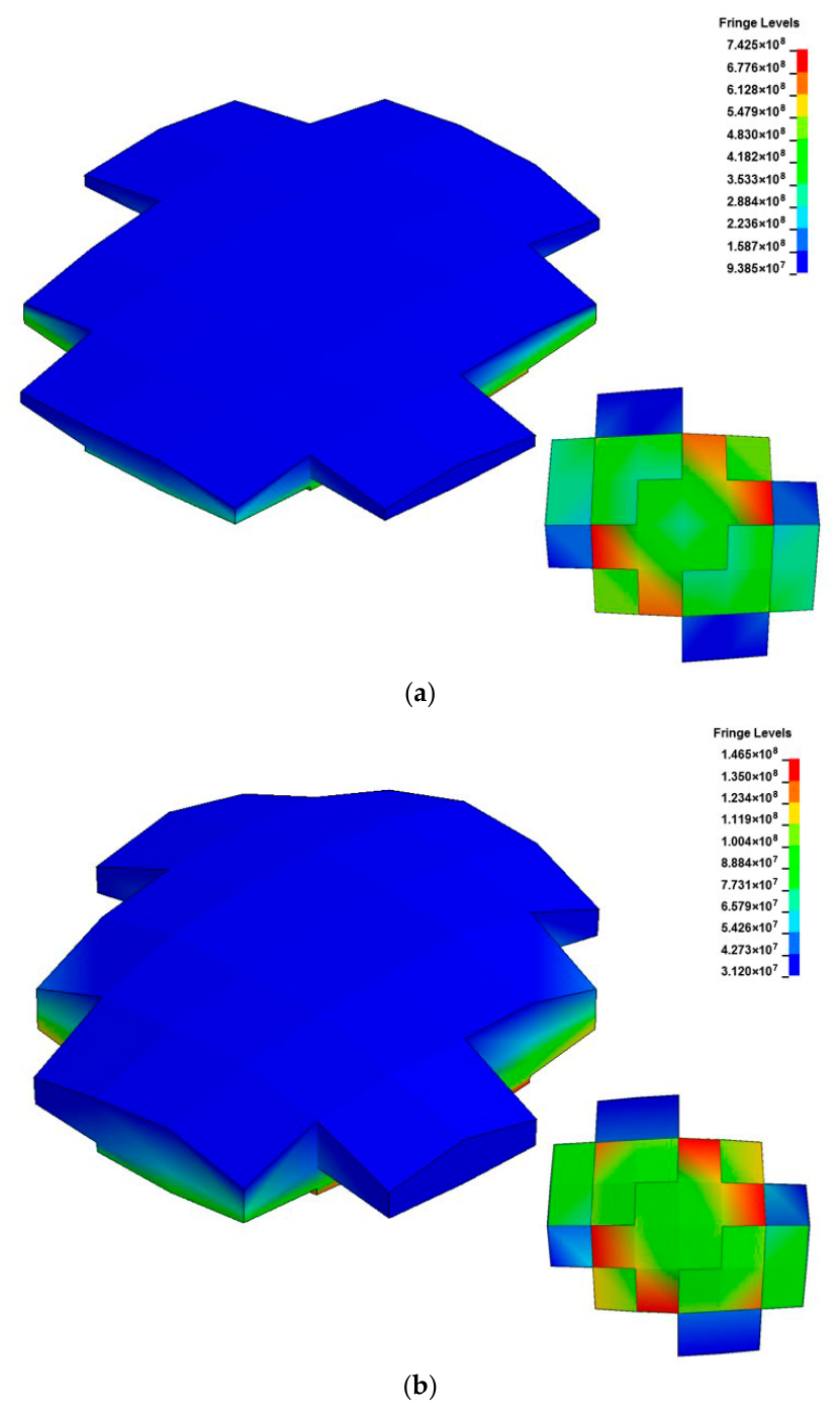
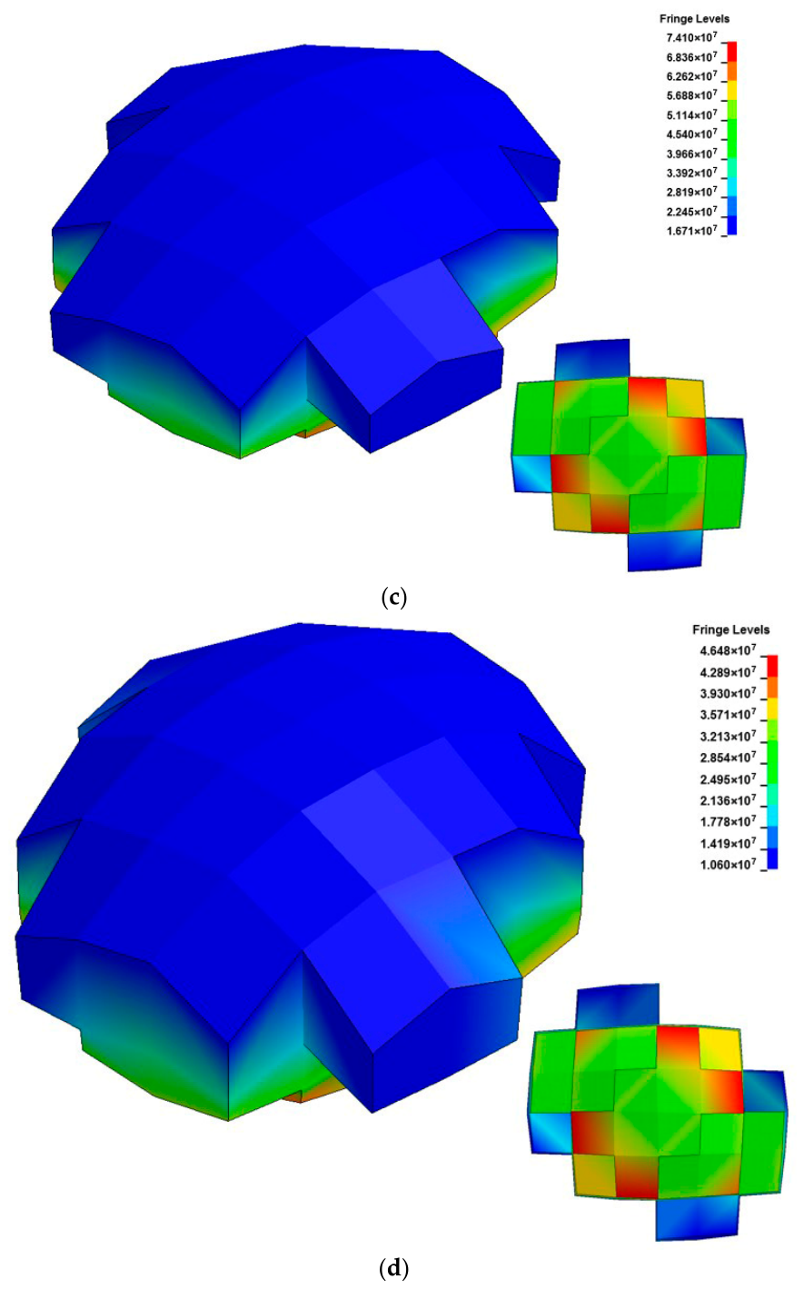
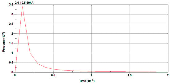
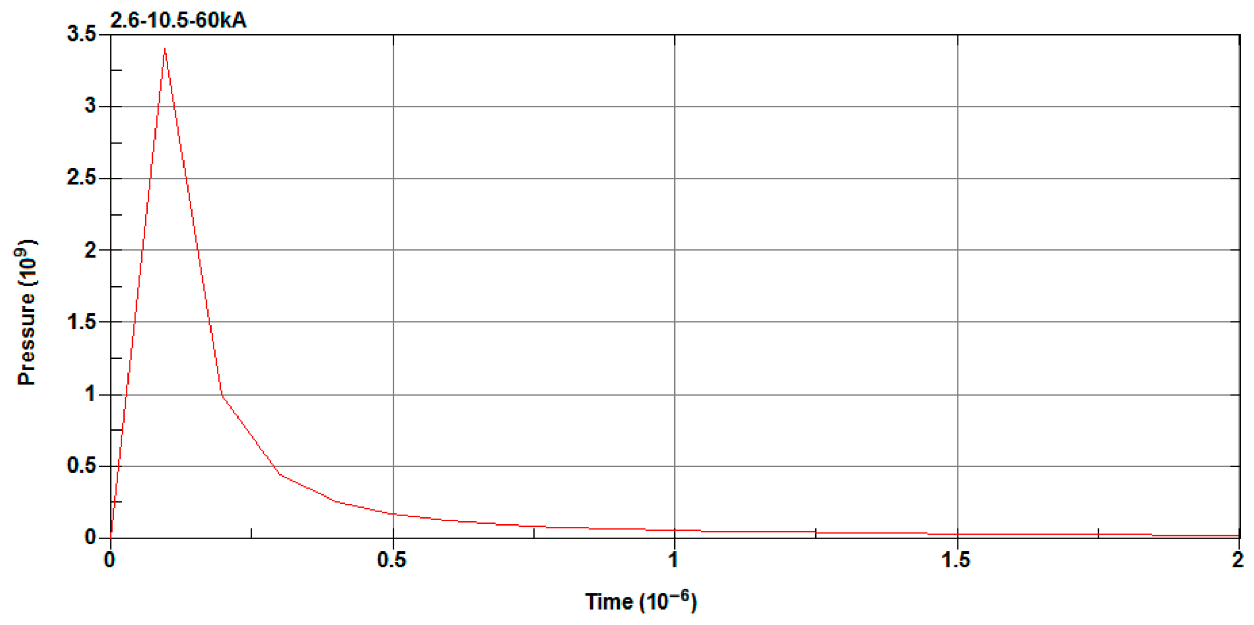
The implosion effect significantly impacts the model’s results. The theoretical reason that helps explain this phenomenon is provided below. Figure 10 shows the pressure contours in the implosion elements at four typical moments. When the explosion shock analysis is completed, the volume of the implosion elements expands rapidly and reaches its maximum value. To some extent, this can reflect the bulging phenomenon around the lightning attachment area. Figure 11 displays the pressure–time history curve of a typical implosion element. The pressure increases sharply at the beginning of the explosion, then decreases sharply during the calculation process, and eventually stabilizes at the minimal value. It can be concluded that the pressure in composite materials is not anisotropic but isotropic when the explosion occurs. This is highly consistent with the law that the mechanical behavior of composite materials exhibits anisotropic characteristics under low pressure and isotropic characteristics under high pressure.
Figure 10.
Pressure contours in the implosion elements. (a) . (b) . (c) . (d) .
Figure 11.
Pressure–time history curve of a typical implosion element.
5. Conclusions
The research on lightning strike damage to fuel tanks can improve the reliability and safety of modern aircraft fuel systems in extreme environments. In this paper, the implosion effect on the composite fuel tank cover subjected to lightning strikes is investigated by numerical simulation. First, the thermal damage behavior of composite structures under lightning strikes is analyzed by the electrical–thermal coupling method. Second, the damage mechanism of the implosion effect on the fuel tank cover is investigated in detail based on the explicit dynamic method. The following conclusions can be drawn from the current study.
The damage mechanism of composite fuel tank covers under lightning strikes mainly includes the Joule heating effect and implosion effect. In the thermal damage study, the element deletion method is adopted to deal with the ablation of composite materials. When an element temperature exceeds the ablation temperature of composite materials, it is deleted. On the other hand, when considering the implosion effect, the explicit dynamic element SOLID164 is used to replace the electrical–thermal element. The original composite material model in the implosion region is replaced with the material model described by the high-explosive material and the JWL equation of state.
It can be concluded from the electrical–thermal analysis that the lightning strike attachment area in the composite fuel tank cover is severely damaged. Based on the ablation criterion, a large number of elements have been deleted in this region. The central part of the cover may be damaged to the extent of being burned through by lightning strikes. Due to the orientation of the surface layer, the damage profile of composite materials is elliptical, and follows the direction of the surface fiber layer.
From the explicit dynamic analysis, it can be seen that the pressure of the implosion elements increases sharply at the beginning of the explosion, then decreases gradually with time. Severe implosion effects can easily lead to the formation of intense detonation shock waves within composite structures. This results in extremely non-uniform stress and pressure distributions in the lightning strike attachment area, which can also cause bulging and wrinkling phenomena. The implosion effect changes the damage mode induced by the electrical–thermal coupling effect, and makes the damage distribution deviate from the initial fiber direction of composite layers.
This research provides references for the lightning protection design of aircraft fuel tanks. The limitations of this study include the temporary absence of lightning arcs. Lightning currents have the characteristics of magnetic fluid, and arc attachment affects the characteristics of lightning loads. In addition, this work needs more experimental results. Recommendations for future work are as follows. The finite element model can be further improved, such as the case of lightning currents applied to the fuel tank cover with bolts, to analyze the damage-forming mechanism of composite structures. There is scope for extensions to the lighting swept stroke in the study of lightning damage.
Author Contributions
F.Y.: data curation. F.Y. and X.X.: formal analysis. F.Y.: methodology. F.Y. and X.X.: writing, review and editing. All authors have read and agreed to the published version of the manuscript.
Funding
This work was supported by the 2023 Doctoral Research Project in Shanxi (QZX-2023038), and the Doctoral Research Start-up Project of Yuncheng University (YQ-2023052 and YQ-2021022).
Data Availability Statement
The original contributions presented in this study are included in the article. Further inquiries can be directed to the corresponding author.
Conflicts of Interest
The authors declare no conflicts of interest.
References
- Millen, S.L.J.; Murphy, A. Modelling and analysis of simulated lightning strike tests: A review. Compos. Struct. 2021, 274, 114347. [Google Scholar] [CrossRef] [Scilit]
- Das, S.; Yokozeki, T. A brief review of modified conductive carbon/glass fibre reinforced composites for structural applications: Lightning strike protection, electromagnetic shielding, and strain sensing. Compos. Part C Open Access 2021, 5, 100162. [Google Scholar] [CrossRef] [Scilit]
- Wang, Y.W.; Zhou, D.; Yan, G.; Wang, Z.J. Experimental and numerical study on residual strength of honeycomb sandwich composite structure after lightning strike. Aerospace 2022, 9, 158. [Google Scholar] [CrossRef] [Scilit]
- Kim, Y.; Jo, J.; Kim, D.; Lee, H.; Myong, R. Effects of lightning on UAM aircraft: Complex zoning and direct effects on composite prop-rotor blade. Aerosp. Sci. Technol. 2022, 124, 107560. [Google Scholar] [CrossRef] [Scilit]
- Duongthipthewa, A.; Lu, M.; Du, K.; Ye, L.; Zhou, L. Experimental and numerical simulation of lightning damage development on composites with/without a carbon-based protection layer. Compos. Struct. 2021, 260, 113452. [Google Scholar] [CrossRef] [Scilit]
- Neyshabouri, H.; Niasati, M. Analysis of the electromagnetic effects on the large floating roof oil tanks by nearby lightning strike based on TLM. J. Electrostat. 2024, 129, 103927. [Google Scholar] [CrossRef] [Scilit]
- Liu, Y.; Fu, Z.; Jiang, A.; Liu, Q.; Liu, B. FDTD analysis of the effects of indirect lightning on large floating roof oil tanks. Electr. Power Syst. Res. 2016, 139, 81–86. [Google Scholar] [CrossRef] [Scilit]
- Ranjith, R.; Myong, R.S.; Lee, S. Computational investigation of lightning strike effects on aircraft components. Int. J. Aeronaut. Space Sci. 2014, 15, 44–53. [Google Scholar] [CrossRef] [Scilit]
- Kamiyama, S.; Hirano, Y.; Okada, T.; Sonehara, T.; Ogasawara, T. I-V characteristics and temperature response of unidirectional CFRP exposed to simulated lightning current in the fiber direction. Compos. Part A Appl. Sci. Manuf. 2022, 162, 107111. [Google Scholar] [CrossRef] [Scilit]
- Tian, X.; Yao, X.; Feng, R.; Sun, J.; Chen, J.; Li, Y.; Le, Y. Damage mechanism analysis for carbon fiber reinforced polymer composites with a fastener under lightning strike. Compos. Struct. 2022, 289, 115465. [Google Scholar] [CrossRef] [Scilit]
- Wang, B.; Zhu, Y.; Ming, Y.; Yao, X.; Tian, X.; Ziegmann, G.; Duan, Y.; Sun, J. Understanding lightning strike induced damage mechanism of carbon fiber reinforced polymer composites: An experimental study. Mater. Des. 2020, 192, 108724. [Google Scholar] [CrossRef] [Scilit]
- Sun, J.; Yao, X.; Xu, W.; Chen, J.; Wu, Y. Evaluation method for lightning damage of carbon fiber reinforced polymers subjected to multiple lightning strikes with different combinations of current components. J. Compos. Mater. 2020, 54, 111–125. [Google Scholar] [CrossRef] [Scilit]
- Sun, J.; Yao, X.; Tian, X.; Chen, J.; Wu, Y. Damage characteristics of CFRP laminates subjected to multiple lightning current strike. Appl. Compos. Mater. 2019, 26, 745–762. [Google Scholar] [CrossRef] [Scilit]
- Boushab, D.; Gharghabi, P.; Lee, J.; Lacy, T.E.; Pittman, C.U.; Mazzola, M.S.; Velicki, A. Lightning arc channel effects on surface damage development on a PRSEUS composite panel: An experimental study. Compos. Part B Eng. 2021, 224, 109217. [Google Scholar] [CrossRef] [Scilit]
- Tian, X.; Sun, J.; Li, Y.; Wang, B.; Yao, X.; Chen, J. Study on the factors influencing the damage modes of carbon fiber-reinforced polymer composites with a fastener under lightning strike conditions. Appl. Compos. Mater. 2022, 29, 711–727. [Google Scholar] [CrossRef] [Scilit]
- Lin, W.H.; Wang, Y.Q.; Yousefpour, K.; Park, C.; Kumar, V. Evaluating the lightning strike damage tolerance for CFRP composite laminates containing conductive nanofillers. Appl. Compos. Mater. 2022, 29, 1537–1554. [Google Scholar] [CrossRef] [Scilit]
- Li, Y.; Sun, J.; Li, S.; Tian, X.; Yao, X.; Wang, B.; Zhu, Y.; Chen, J. Experimental study of the damage behaviour of laminated CFRP composites subjected to impulse lightning current. Compos. Part B Eng. 2022, 239, 109949. [Google Scholar] [CrossRef] [Scilit]
- Larsson, A.; Lalande, P.; Bondiou-Clergerie, A. The lightning swept stroke along an aircraft in flight. Part II: Numerical simulations of the complete process. J. Phys. D Appl. Phys. 2000, 33, 1876–1883. [Google Scholar] [CrossRef] [Scilit]
- Wan, G.; Dong, Q.; Zhi, J.; Guo, Y.; Yi, X.; Jia, Y. Analysis on electrical and thermal conduction of carbon fiber composites under lightning based on electrical-thermal-chemical coupling and arc heating models. Compos. Struct. 2019, 229, 111486. [Google Scholar] [CrossRef] [Scilit]
- Featherston, C.; Eaton, M.J.; Evans, S.; Holford, K.M.; Pullin, R.; Cole, M. Development of a methodology to assess mechanical impulse effects resulting from lightning attachment to lightweight aircraft structures. Appl. Compos. Mater. 2010, 24–25, 129–134. [Google Scholar] [CrossRef] [Scilit]
- Lee, J.; Lacy, T.E.; Pittman, C.U. Coupled thermal electrical and mechanical lightning damage predictions to carbon/epoxy composites during arc channel shape expansion. Compos. Struct. 2021, 255, 112912. [Google Scholar] [CrossRef] [Scilit]
- Lee, J.; Lacy, T.E.; Pittman, C.U. Lightning mechanical damage prediction in carbon/epoxy laminates using equivalent air blast overpressure. Compos. Part B Eng. 2021, 212, 108649. [Google Scholar] [CrossRef] [Scilit]
- Shi, Y.; Du, B.; Liu, Q.; Mai, Y.; Zhao, Y.; Gao, J. Prediction model of gas expansion and electro-thermal coupling regarding lightning damage to carbon fiber composites. Appl. Compos. Mater. 2021, 28, 1221–1236. [Google Scholar] [CrossRef] [Scilit]
- Wan, G.; Dong, Q.; Li, T.; Sun, X.; Jia, Y. Simulated analysis of lightning-induced mechanical damages in fiber reinforced composites based on a pyrolysis-affected damage constitutive model. Appl. Compos. Mater. 2022, 29, 2165–2184. [Google Scholar] [CrossRef] [Scilit]
- Shan, Z.; Liu, X.; Lu, X.; Ma, K.; Xiao, H.; Tian, M. Analysis of lightning ablation damage of composite laminates with multiple fasteners. Adv. Mech. Eng. 2022, 14, 1–12. [Google Scholar] [CrossRef] [Scilit]
- Cheng, S.N. Study on Aluminum Mesh Protection and Residual Tensile Strength of Composite Connectors Subject to Lightning Strike. Master’s Thesis, Northwestern Polytechnical University, Xi’an, China, 2022. [Google Scholar]
- Abdelal, G.; Murphy, A. Nonlinear numerical modelling of lightning strike effect on composite panels with temperature dependent material properties. Compos. Struct. 2014, 109, 268–278. [Google Scholar] [CrossRef] [Scilit]
- Chen, H.; Tang, W.H.; She, J.H.; Ran, X.W.; Xu, Z.H. The PUFF equation of state parameters for synthetic rubber. Mech. Mater. 2011, 43, 69–74. [Google Scholar] [CrossRef] [Scilit]
- Huang, X.; Tang, W.H.; Jiang, B.H. A modified anisotropic PUFF equation of state for composite materials. J. Compos. Mater. 2012, 46, 499–506. [Google Scholar] [CrossRef] [Scilit]
- Hirano, Y.; Katsumata, S.; Iwahori, Y.; Todoroki, A. Artificial lightning testing on graphite/epoxy composite laminate. Compos. Part A Appl. Sci. Manuf. 2010, 41, 1461–1470. [Google Scholar] [CrossRef] [Scilit]

Disclaimer/Publisher’s Note: The statements, opinions and data contained in all publications are solely those of the individual author(s) and contributor(s) and not of MDPI and/or the editor(s). MDPI and/or the editor(s) disclaim responsibility for any injury to people or property resulting from any ideas, methods, instructions or products referred to in the content. |
© 2026 by the authors. Licensee MDPI, Basel, Switzerland. This article is an open access article distributed under the terms and conditions of the Creative Commons Attribution (CC BY) license.