


Highlights
What are the main findings?
- The double-layer coatings are deposited on an S30408 surface under different welding currents.
- Welding current critically determines martensite fraction and grain refinement.
- The 200 A coating shows the finest structure, highest hardness and lowest wear mass loss.
- The 230 A coating exhibits the most positive corrosion potential in 3.5 wt.% NaCl solution.
- A clear trade-off between wear and corrosion resistance is revealed, depending on welding current.
What are the implications of the main findings?
- Fine lath martensite with dispersed nano-carbides is key to wear resistance at 200 A.
- Higher heat input at 230 A promotes elemental homogenization and improves corrosion resistance.
- A current of 200 A can better balance friction-wear and corrosion resistance properties with economic efficiency.
- This work offers practical guidance for surface enhancement of S30408 steel components.
Abstract
Corrosion-resistant coatings with a double-layer structure are deposited on the surface of S30408 stainless steel at welding currents of 170 A, 200 A, and 230 A using metal active gas (MAG) arc welding technology. The influence of welding current on the microstructure, microhardness, wear resistance, and electrochemical corrosion behavior of the coating is systematically studied. The results show that the coating produced at 200 A exhibited the finest martensitic structure, the highest microhardness (~450 HV), and the lowest mass loss (139.9 mg), indicating its superior wear resistance. In contrast, the coating fabricated at 230 A displayed the most positive corrosion potential (−0.302 V vs. saturated calomel electrode (SCE)) in 3.5 wt.% NaCl solution, which is attributed to enhanced elemental homogenization arising from the higher heat input. This paper clarifies the critical role of welding current in balancing wear and corrosion performance and provides a practical guideline for the cost-effective surface enhancement of S30408 steel components.
1. Introduction
S30408 austenitic stainless steel is widely used in chemical processing, marine engineering, food equipment, and other industrial sectors owing to its favorable combination of formability, toughness, and corrosion resistance [1,2,3,4,5]. However, its lower hardness (not exceeding 200 HV) and poor resistance to abrasive and adhesive wear greatly limit the further application of such materials [6,7]. Numerous studies have shown that premature failure frequently occurs when S30408 austenitic stainless-steel components are exposed to harsh environments involving solid particle erosion, sliding friction, or combined wear–corrosion effects [8,9,10,11]. Replacing the entire component with a high-performance alloy or applying bulk alloying can mitigate these problems, yet such approaches are economically prohibitive and technologically complex [12,13]. At the same time, improper matching of alloying elements during the alloying process may significantly degrade the performance of austenitic stainless steel [14]. Against this background, surface engineering technology is recognized as an effective method to selectively modify stainless steel substrates while preserving their excellent inherent properties, and has become the most cost-effective and feasible strategy for industrial applications [15,16,17,18].
Among the available surface modification techniques, cladding processes that produce a metallurgically bonded overlay are particularly attractive because they allow for targeted enhancement of surface properties [19,20,21,22]. High-energy-density methods, such as laser cladding and plasma transferred arc welding, have been extensively investigated for depositing Ni-based [8,9,10,11], Co-based, and Fe-based wear- and corrosion-resistant coatings on stainless steels [23,24,25,26,27]. For instance, Yuan et al. [21] demonstrated that Ni45 alloy coatings produced by laser cladding can achieve high hardness and wear resistance. Meanwhile, Li et al. [22] fabricated WC + TiC-reinforced Ni-based composite coatings with superior sliding wear performance. Despite these successful demonstrations, the high equipment cost, relatively low deposition rate, and limited accessibility of large or geometrically complex components restrict the wider adoption of laser- and plasma-based processes in many industrial contexts [21,22,23,24].
Arc-based cladding methods, including gas tungsten arc (GTA) and gas metal arc welding-based processes, offer significantly higher deposition efficiency, lower capital investment, and greater on-site versatility [9,10]. Metal active gas (MAG) arc cladding, which uses a consumable wire electrode and an active shielding gas, is particularly suitable for the surface rehabilitation and strengthening of large- and medium-sized engineering parts [28,29,30]. However, compared with the extensive literature on laser and plasma cladding, systematic studies devoted to MAG arc cladding of stainless-steel substrates with wear- and corrosion-resistant layers remain relatively scarce. A critical challenge in MAG cladding is the control of heat input: an excessively low heat input may cause a lack of fusion and porosity, whereas an overly high heat input can lead to substrate overheating, grain coarsening, dilution-induced chemical inhomogeneity, and deterioration of corrosion resistance [28]. As the primary parameter governing heat input, welding current profoundly influences the cooling rate, solidification conditions, and subsequent solid-state phase transformations, which, in turn, dictate the volume fraction, morphology, and distribution of strengthening phases such as martensite and carbides [31,32]. Although several investigations have addressed the effect of welding current on the microstructure and hardness of arc-clad layers, few have explicitly linked the thermal cycle to both wear resistance and corrosion resistance in a single study [32,33,34]. In addition, a clear understanding of the trade-off between these two performance aspects under the same process window has not yet been established.
To address this knowledge gap, the present study aims to fabricate wear- and corrosion-resistant coatings on S30408 stainless steel by MAG arc cladding using a commercial YD110Mo-G martensitic flux-cored wire. By systematically varying the welding current (170, 200, and 230 A) and performing double-layer deposition, the evolution of the phase composition, microstructural features (lath martensite, retained austenite, and carbides), and the resulting properties—hardness, wear resistance, and electrochemical corrosion behavior—are evaluated. The underlying relationships among welding current, microstructure, and performance are elucidated, and the interplay between wear resistance and corrosion resistance is discussed from the perspective of wear–corrosion synergy. This work aims to provide a theoretical foundation and practical processing guidance for the cost-effective fabrication of high-performance coatings on S30408 components operating under combined wear and corrosion conditions.
2. Materials and Methods
2.1. Base Material and Filler Wire
Hot-rolled S30408 austenitic stainless-steel plates(Baosteel Stainless Steel Co., Ltd., Shanghai, China) are processed into small blocks with dimensions of 200 m × 20 m × 10 m, serving as the substrate material. Then, the chemical composition of the substrate is analyzed, and the results are presented in Table 1. A commercial flux-cored wire, YD110Mo-G (Tianjin Golden Bridge Welding Materials Group Co., Ltd., Tianjin, China; diameter 1.2), is selected as the cladding consumable. This wire is designed to produce a martensitic overlay with high hardness and good wear resistance and is a classic choice for hardfacing on tough stainless-steel substrates. The chemical composition of the wire is listed in Table 2. Prior to cladding, the substrate surface is ground to remove the oxide scale and cleaned with acetone to eliminate oil and contaminants.
Table 1.
Chemical composition of S30408 stainless steel (wt.%).
Table 2.
Chemical composition of YD110Mo-G flux-cored wire (wt.%).
2.2. MAG Cladding Procedure
A Fronius TPS 4000 digital pulsed metal active gas (MAG) welding power source is employed in the direct current electrode positive (DCEP) mode. The shielding gas consists of 80% argon (Ar) and 20% CO2, with a flow rate of 15–20 L/min. Two layers are deposited on the substrate with a 40% bead overlap. After the first layer is deposited, the workpiece is allowed to cool in still air to an interpass temperature of 200–300 °C before the second layer is applied. Three sets of specimens are prepared using welding currents of 170 A, 200 A, and 230 A, while the arc voltage is maintained in the range of 28–32 V and the travel speed is adjusted between 200 and 400 mm/min. The detailed cladding parameters are summarized in Table 3.
Table 3.
MAG cladding parameters.
2.3. Characterization Methods
Metallographic specimens are sectioned perpendicular to the cladding direction, ground, polished, and etched with a solution of FeCl3 + HCl + H2O. Microstructural observations are performed using an Axio Zeiss optical microscope. The phase composition of the top surface of the clad layers is analyzed by X-ray diffraction (XRD) on a DX-2700B diffractometer (Dandong Haoyuan Instrument Co., Ltd., Dandong, China) with Cu Kα radiation; scans are carried out over a 2θ range of 20–100° with a step size of 0.03°. Microhardness profiles are measured along the cross-section from the coating surface to the substrate using an MHV2000 digital micro-Vickers hardness tester (Shanghai Shangcai Testing Machine Co., Ltd., Shanghai, China) under a load of 1.96 N and a dwell time of 15 s. Dry sliding wear tests are conducted at room temperature on an MMS-2A pin-on-ring tribometer (Jinan Hengxu Testing Machine Technology Co., Ltd., Jinan, China). The counterbody is a quenched GCr15 steel ring (outer diameter of 40 mm, inner diameter of 16 mm, thickness of 10 mm). The tests are performed under a normal load of 200 N at a rotational speed of 400 r/min for 40 min, corresponding to a total of 16,000 revolutions. The mass loss of each specimen is measured using an electronic balance (Sartorius Scientific Instruments (Beijing) Co., Ltd., Beijing, China) with a precision of 0.01 mg, and the coefficient of friction is recorded continuously. After wear testing, the worn surfaces are examined by optical microscopy (Carl Zeiss, Shanghai, China) to identify the wear mechanisms. Electrochemical corrosion behavior is evaluated in a 3.5 wt% NaCl solution at ambient temperature using a CS350 electrochemical workstation (Wuhan CorrTest Instruments Corp., Ltd., Wuhan, China). A conventional three-electrode cell is employed, with the specimen as the working electrode, a saturated calomel electrode (SCE) as the reference electrode, and a platinum sheet as the counter electrode. Potentiodynamic polarization curves are recorded at a scan rate of 1 mV/s after 40 min of open-circuit potential stabilization. The corrosion potential and corrosion current density are extracted from the polarization curves by Tafel extrapolation.
3. Results and Discussion
3.1. Microstructural Evolution as a Function of Welding Current
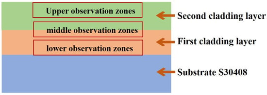
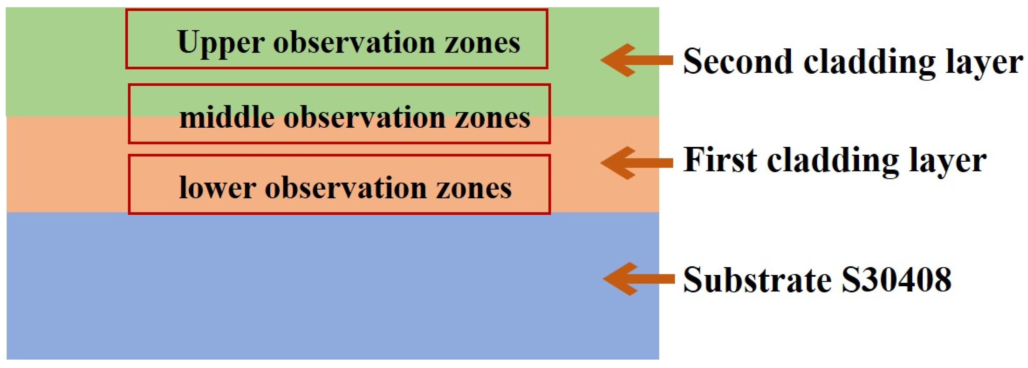
The overall architecture of the double-layer clad system is illustrated schematically in Figure 1. From this, the observation zones for microstructural analysis are indicated: the top region of the second layer, the middle region (which spans the interface between the first and second layers), and the bottom region near the fusion line with the substrate.
Figure 1.
Schematic illustration of the observation zones for microstructural analysis.
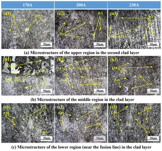
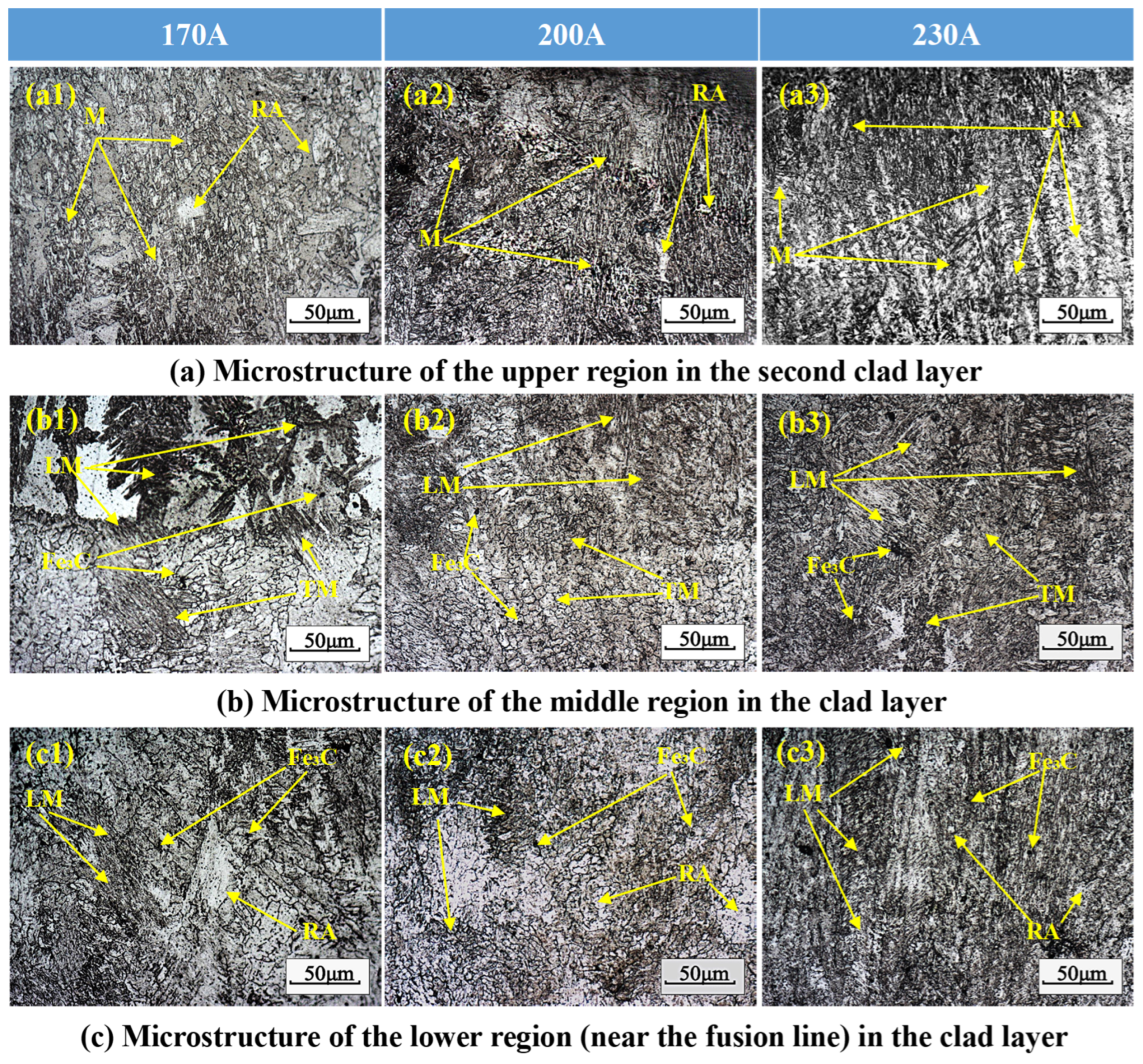
Figure 2 presents a comprehensive set of optical micrographs taken from the top, middle, and bottom regions of the coatings produced at different welding currents. It can be seen that the phase composition in all specimens consisted predominantly of lath martensite (LM), retained austenite (RA), tempered martensite (TM), and a small fraction of carbides (Fe3C), in agreement with the XRD results discussed later. In the meantime, the welding current exerted a pronounced influence on the grain size, phase composition, and morphological features across the coating thickness.
Figure 2.
Optical micrographs of the clad layers under different welding currents. (a1–a3) represent the microstructure of the upper region of the second cladding layer at 170 A, 200 A, and 230 A, respectively. (b1–b3) represent the microstructure of the middle region of the cladding layer at 170 A, 200 A, and 230 A, respectively. (c1–c3) represent the microstructure of the lower region of the cladding layer (near the fusion line) at 170 A, 200 A, and 230 A, respectively. (M: martensite; RA: retained austenite; LM: lath martensite; TM: tempered martensite; Fe3C: carbides).
It can be seen from Figure 2(a1–a3) that the sample surface is primarily composed of elongated grains, exhibiting the characteristics of an MAG arc welding coating. The main components of these elongated grains are martensite and residual austenite, with martensitic transformation occurring during the second cooling process. Research has shown that the formation of elongated grains on the sample surface is mainly attributed to several factors such as thermal field regulation, compositional undercooling, and nucleation conditions. Firstly, during the MAG welding process, the surface of the molten pool comes into direct contact with the shielding gas, and heat dissipation occurs uniformly in multiple directions. This significantly reduces the temperature gradient and increases the solidification rate, thereby inhibiting the formation of oriented columnar crystals and promoting the growth of elongated crystals. Secondly, reasonable control of heat input will further reduce the temperature gradient inside the melt pool, expand the undercooled region of the composition, and provide sufficient space for the nucleation of elongated grains. Furthermore, the presence of a certain amount of Cr element in the substrate material and welding wire can enhance the undercooling of the melt pool, act as a heterogeneous nucleation core, and limit the directional growth of grains, thereby promoting the formation and growth of elongated grains. According to the information provided in the middle region (Figure 2(b1–b3)), the sensitivity of the microstructure to the welding current becomes evident. As can be seen from Figure 2(b1), when the current is 170 A, a pronounced layered morphology is observed, consisting of an upper zone of lath martensite and a lower zone of tempered martensite decorated with fine carbide precipitates. The tempering effect originates from the thermal cycle of the second pass, which reheats the upper portion of the first layer. As the current increases to 200 A, the martensitic laths become finer and the layering remains visible but less distinct, as shown in Figure 2(b2). However, when the current is increased to 230 A, the layered structure basically disappears, and the grain size becomes significantly coarser (see Figure 2(b3)). This is because the higher heat input at 230 A prolongs the time that the inter-layer zone spends at elevated temperatures, thereby promoting recovery and grain growth, and may reduce the degree of martensitic transformation because of a lower cooling rate. It can be seen from Figure 2(c1–c3) that near the fusion line at the bottom of the coating, the microstructure is primarily composed of martensite and retained austenite. The volume fraction of lath martensite increases markedly with increasing welding current, and the transformation becomes more homogeneous. The largest heat input at 230 A raises the dilution ratio, introducing additional Cr, Ni and Mo from substrate into the cladding, which shifts the continuous cooling transformation (CCT) curve to the right and decreases the critical cooling rate for martensite formation, thereby enhancing hardenability. In the meantime, fine carbides precipitate within and around the martensite laths, contributing to precipitation strengthening.
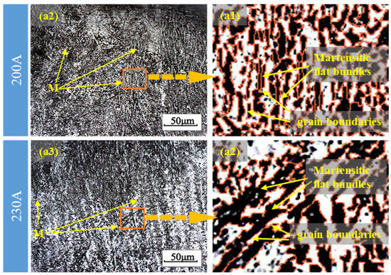
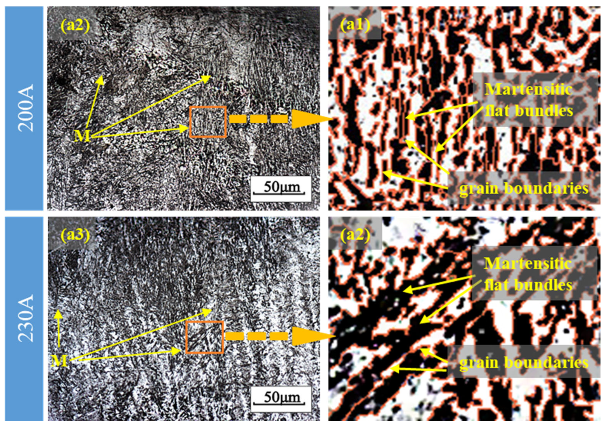
Figure 3 shows the locally magnified microstructures of the sample surfaces at 200 A and 230 A corresponding to Figure 2(a2) and Figure 2(a3), respectively. As shown in Figure 3(a1) and Figure 3(a2), the magnified regions clearly reveal martensitic flat bundles and their boundaries.
As can be seen from Figure 3(a1,a2), compared to the 200 A sample, the number of martensitic flat bundles per unit area in the 230 A sample is significantly reduced, while the bundle width is noticeably increased. This demonstrates that increasing the welding current (i.e., increasing the heat input) promotes the coarsening of martensitic flat bundles. The reason for this is that the higher heat input prolongs the time the inter-layer zone spends at elevated temperatures, promoting recovery and growth, and the lower cooling rate reduces the degree of martensitic transformation.
3.2. Phase Analysis
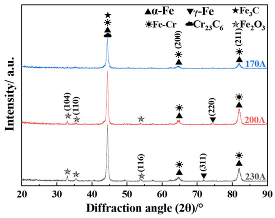
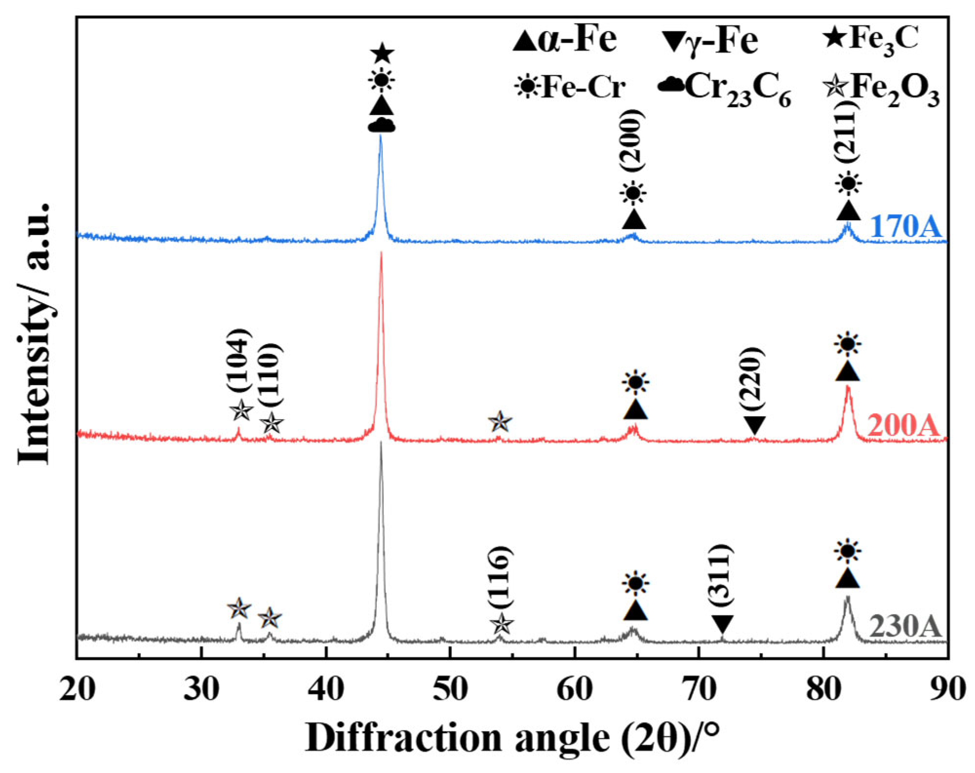
XRD patterns of the top surfaces of the three coatings are shown in Figure 4. It can be seen that under different welding currents, the α-Fe (martensite) and Fe-Cr (solid solution) phases can be identified on the sample surface. Obviously, this result is related to the presence of a large amount of Fe and Cr elements in the substrate material and welding wire. In addition, diffraction peaks of the M3C-type carbide (Fe3C, Cr23C6) phase, which are highly overlapped with those of the α-Fe (martensite) and Fe-Cr (solid solution) phases, are also observed in the pattern. However, due to the low content of M3C-type carbides, their existence still needs further confirmation. It is worth noting that weak diffraction peaks of γ-Fe (retained austenite) are also observed in the pattern. This is due to the combined effect of various factors, including material composition, welding thermal cycle, and phase transformation characteristics, which result in a relatively low content of γ-Fe on the coating surface. In addition, the use of a Cu target for the detection of γ-Fe generates a large amount of fluorescent background noise, which significantly reduces the signal-to-noise ratio of the γ-Fe diffraction peak, thereby significantly reducing its diffraction peak intensity. Compared to the 170 A sample, some weak Fe2O3 diffraction peaks are also identified on the surfaces of the 200 A and 230 A samples. Apparently, this is related to the slight oxidation of the coating surface induced by increasing the welding current. In addition, it can also be found that the intensity ratio of the martensite peaks to the austenite peaks varies with the welding current, qualitatively indicating that the martensite volume fraction is highest in the 200 A specimen. This is consistent with the microstructural observation (see Figure 2) that 200 A provides a favorable cooling rate that promotes martensitic transformation while limiting excessive grain coarsening and carbide over-tempering.
Figure 4.
XRD patterns of the clad layers produced at 170 A, 200 A, and 230 A. The numbers in parentheses, e.g., (110), (200), (211), and (311), denote the crystal planes (Miller indices).
3.3. Mechanical Properties
3.3.1. Microhardness Profiles
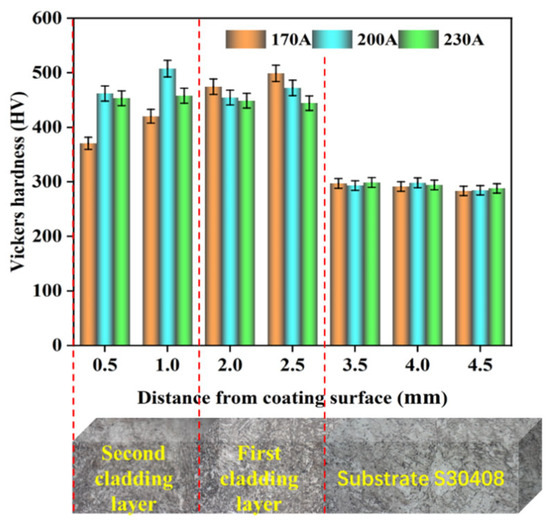
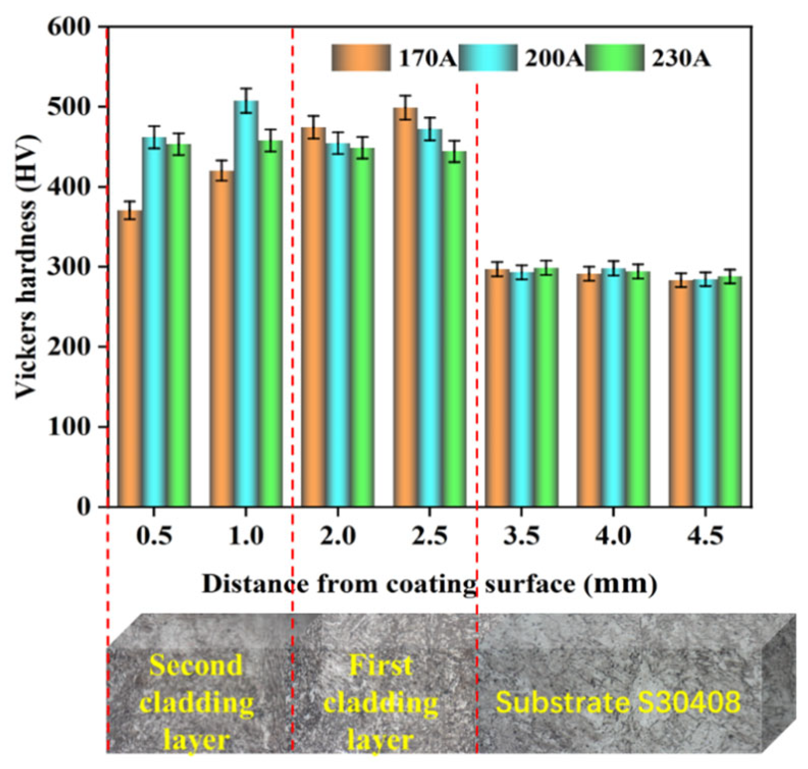
The through-thickness micro-hardness distributions are plotted in Figure 5. It can be seen that all coatings are significantly harder than the S30408 substrate (~190–210 HV), confirming the effectiveness of the martensitic overlay. Among them, the 200 A coating exhibits the highest hardness values, reaching approximately 450 HV near the sample surface, and maintains a relatively uniform hardness gradient. For the 170 A sample, the hardness of the first layer is anomalously higher than that of the second layer. This can be explained by the low heat input at 170 A, which results in a very fast cooling rate and a finer, highly stressed martensitic structure in the first layer; the second layer, benefiting from the preheating effect of the first, cools slower and develops a slightly softer tempered structure. In addition, it can be observed that the hardness of the 230 A sample gradually decreases from the surface towards the substrate, with its peak value being lower than that of the 200 A sample. This is attributed to the fact that higher heat input promotes grain coarsening, partial tempering of martensite, and an increase in the fraction of retained austenite, all of which reduce the overall hardness.
Figure 5.
Microhardness profiles across the clad layers and substrate for different welding currents. The red dashed lines indicate the boundaries between the second cladding layer, the first cladding layer, and the substrate (S30408).
3.3.2. Wear Resistance and Mechanisms
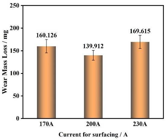
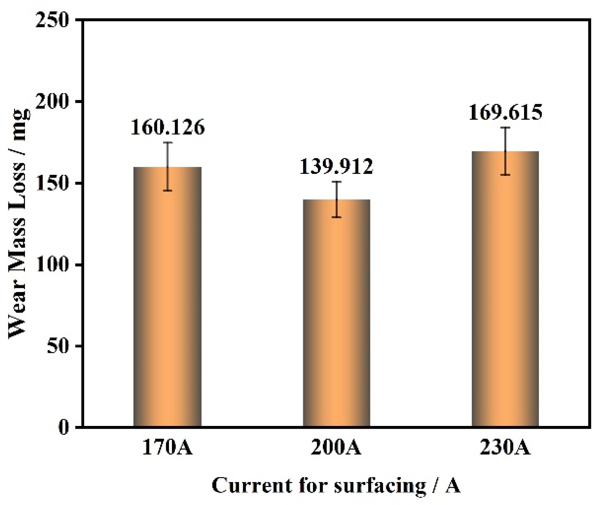
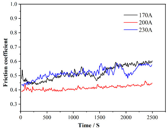
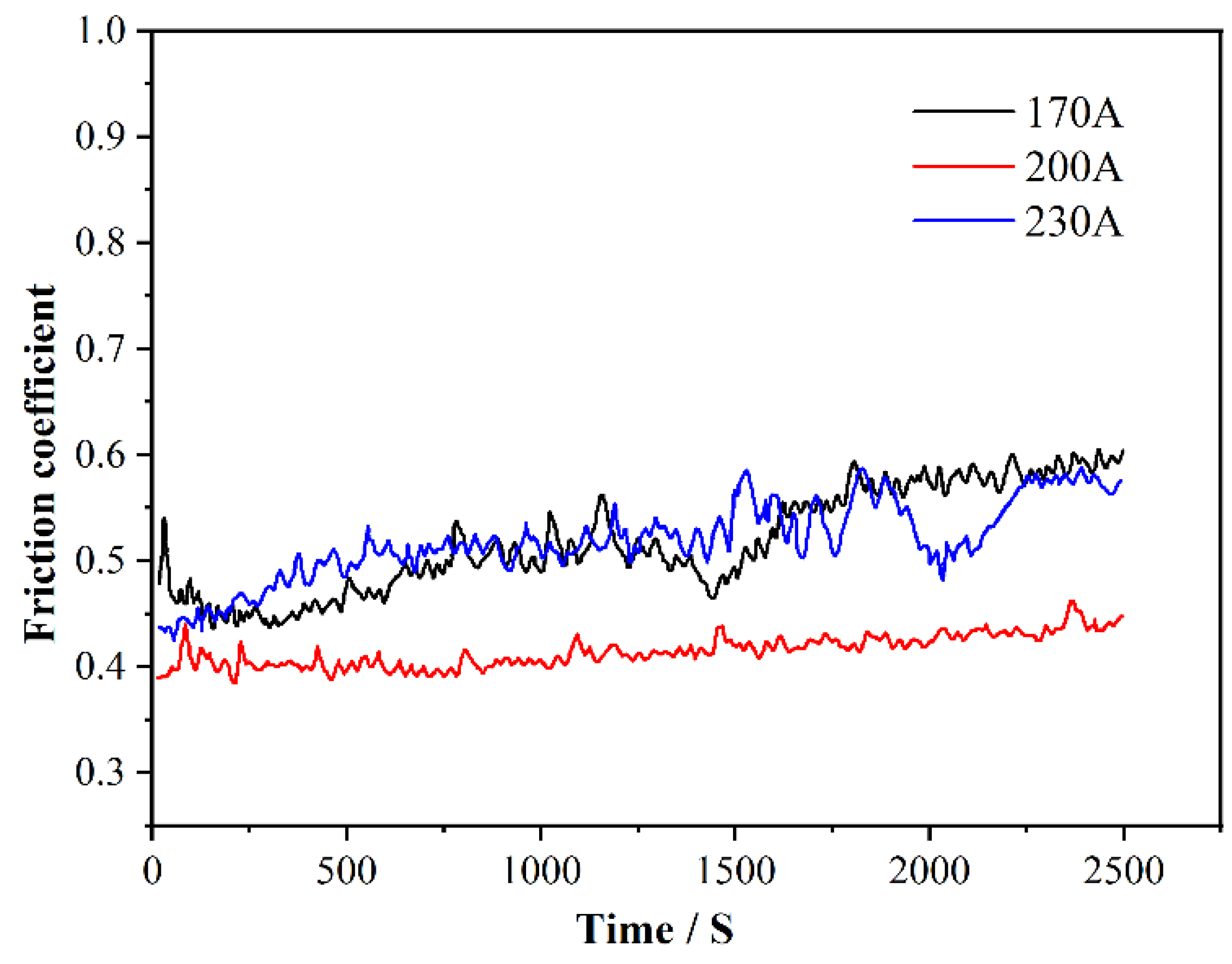
The mass loss after 16,000 sliding cycles is compared in Figure 6. It can be seen that the coating prepared at 200 A shows the lowest mass loss (139.9 mg), whereas the 170 A and 230 A specimens exhibit higher and comparable mass losses (160.1 mg and 169.6 mg, respectively). The evolution of the coefficient of friction (COF) is presented in Figure 7. Based on these results, the 200 A specimen has the lowest average coefficient of friction (COF) and the most stable friction curve, which shows a gradual increasing trend with minimal fluctuations. In contrast, the 170 A and 230 A curves show more pronounced running-in stages and sporadic fluctuations resulting from the generation and ejection of wear debris.
Figure 6.
Mass loss of the clad layers after 16,000 wear cycles.
Figure 7.
Friction coefficient curves for the coatings produced at 170 A, 200 A, and 230 A.
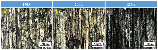
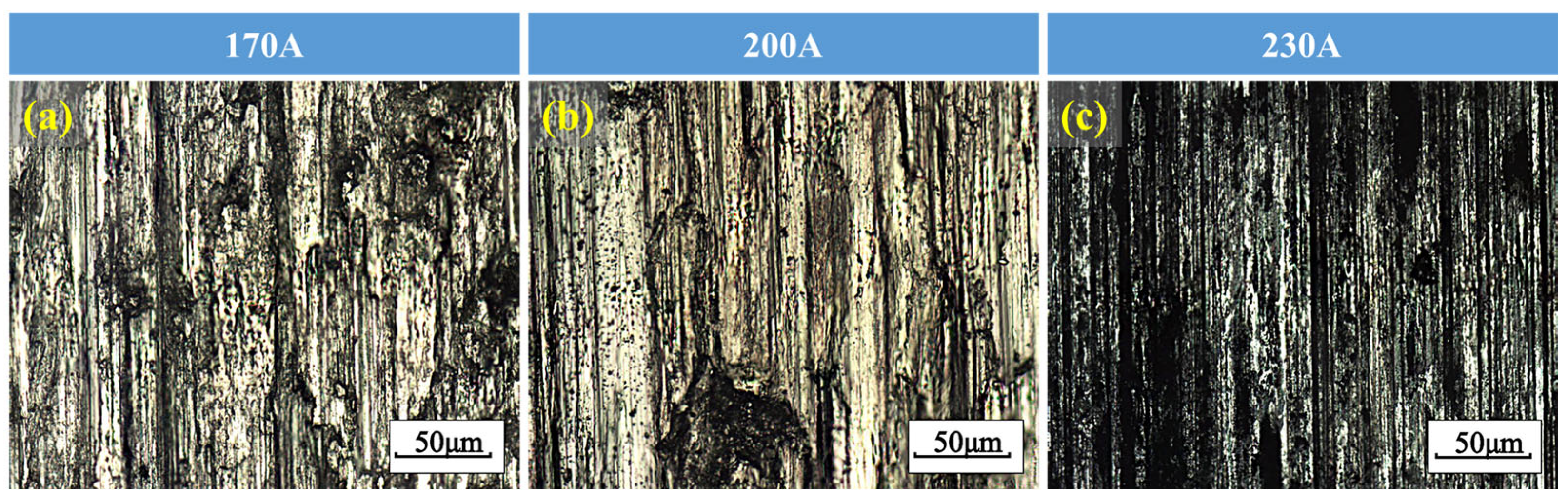
The worn surface morphologies are shown in Figure 8. It can be seen that all coatings underwent predominantly abrasive wear, as evidenced by parallel grooves and plowing marks along the sliding direction. As shown in Figure 8a, the 170 A specimen exhibits relatively deep, sparsely distributed grooves accompanied by local delamination pits. The high hardness, coupled with a certain degree of brittleness of this coating, promotes the micro-cracking and detachment of hard Fe–Cr alloy particles. These detached particles then act as third-body abrasives and intensify plowing. Meanwhile, the 200 A specimen (Figure 8b) presents the smoothest worn surface, with only shallow grooves and sporadic small pits, reflecting its balanced combination of high hardness and adequate toughness. The 230 A specimen (Figure 8c) shows deeper grooves than its 200 A counterpart, together with fine pores. Excessive heat input at 230 A may have caused partial evaporation of Mo and Cr, increased the dilution ratio, and reduced the martensite volume fraction. This results in a softer matrix that is more susceptible to micro-plowing. Moreover, the fine pores probably originate from microvoid coalescence promoted by elemental segregation.
Figure 8.
Worn surface images of the coatings produced at different welding currents. (a) 170 A. (b) 200 A. (c) 230 A.
The above results demonstrate that the wear resistance of the clad layers is primarily governed by the size and distribution of lath martensite, the precipitation state of carbides, and the amount of retained austenite. A moderate welding current of 200 A produces a fine martensitic matrix with well-dispersed carbide particles that effectively resist micro-cutting and abrasive penetration, while a small fraction of retained austenite may contribute to toughness and retard crack propagation. In contrast, both insufficient (170 A) and excessive (230 A) heat input degrade the wear resistance: the former leads to structural heterogeneity and brittle behavior, and the latter induces grain coarsening, phase dilution, and softening.
3.4. Electrochemical Corrosion Behavior
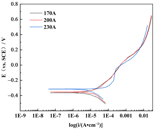
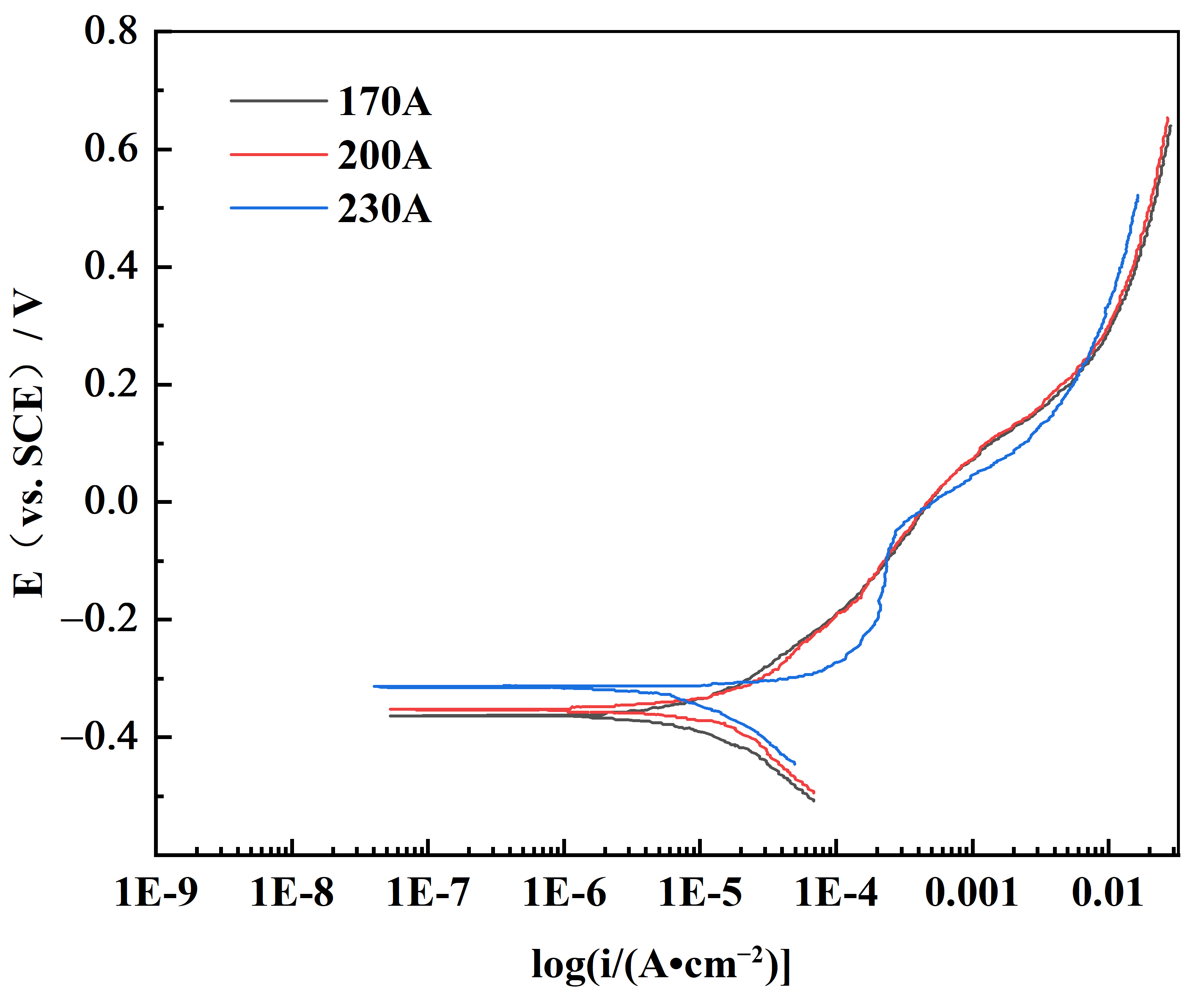
The potentiodynamic polarization curves measured in 3.5 wt.% NaCl solution are shown in Figure 9, and the corresponding electrochemical parameters are summarized in Table 4. The three coatings exhibited similar corrosion current density (Icorr) values, but their corrosion potentials (Ecorr) were notably different. As the welding current increased from 170 A to 230 A, Ecorr shifted positively from −0.369 V to −0.302 V vs. SCE, indicating a progressively lower thermodynamic tendency for corrosion. It also can be seen from Figure 8 that the polarization curve of the sample under a welding current of 230 A exhibited two distinct deformations. The vertical region represents a clear passivation zone, indicating that the sample exhibits optimal corrosion resistance.
Figure 9.
Potentiodynamic polarization curves of the clad layers in 3.5 wt.% NaCl solution.
Table 4.
Electrochemical parameters extracted from the polarization curves.
The superior corrosion resistance of the 230 A coating can be attributed to the enhanced elemental homogenization driven by the higher heat input. A larger heat input raises the peak temperature and prolongs the time spent at high temperatures, facilitating the dissolution of Cr and Mo into the austenite/martensite matrix. Both elements are critical for forming a stable, protective passive film; improved solid-solution uniformity reduces the number of preferential sites for film breakdown. In addition, higher thermal cycling promotes a more homogeneous distribution of secondary phases, thereby mitigating micro-galvanic coupling between carbides and the surrounding substrate. Although the grain size increases somewhat at 230 A, the beneficial effect of compositional homogenization dominates the electrochemical response, resulting in the most positive corrosion potential.
3.5. Process–Microstructure–Property Relationship and Wear–Corrosion Synergistic Mechanism
The above results establish a clear current–microstructure–property nexus. The welding current directly determines the heat input, which, in turn, governs the cooling rate, peak temperature, and dilution level. At 170 A, rapid cooling produces a fine yet heterogeneous microstructure with a high density of internal stresses; wear resistance is impaired by brittleness and delamination. At 200 A, the thermal conditions favor the formation of a fine, uniformly distributed lath martensite framework with optimized carbide precipitation, delivering the highest hardness and the best sliding wear resistance. At 230 A, slower cooling and increased dilution coarsen the grains, increase the retained austenite fraction, and reduce martensitic hardness. However, these same thermal conditions promote the homogenization of alloying elements, which enhances the stability of the passive film and ultimately produces the best corrosion resistance. This divergent trend highlights a classic trade-off in surface engineering for service environments where wear and corrosion occur concurrently. In a pure sliding wear scenario, the 200 A coating is clearly the optimal choice.
In a corrosion-dominated environment, the 230 A coating outperforms the others. In many practical applications—such as components in chemical pumps, marine shafts, or food processing machinery—wear and corrosion act synergistically: corrosion roughens the surface and facilitates mechanical material removal, while wear continuously strips away the passive film and exposes fresh reactive surfaces [35,36,37,38]. For such wear–corrosion synergy environments, a coating must simultaneously possess sufficient mechanical integrity and chemical stability. The present findings suggest that a current of 200 A achieves the most favorable balance for combined wear–corrosion performance, as it provides excellent wear resistance while maintaining a corrosion resistance only slightly inferior to the 230 A condition. This insight can serve as a practical guideline for selecting welding current when designing coatings for S30408 components exposed to complex tribo-corrosive conditions.
4. Conclusions
Double-layer wear- and corrosion-resistant coatings are fabricated on S30408 stainless steel by MAG arc cladding with a YD110Mo-G flux-cored wire, and the effects of welding current are systematically investigated. The main conclusions are as follows:
- (1)
- The coatings are composed of lath martensite, retained austenite, and a small amount of carbides. The welding current significantly influences the martensite content and the refinement of the microstructure. The highest martensite fraction and the finest grain structure are achieved at 200 A.
- (2)
- The coating produced at 200 A exhibits the highest microhardness (~450 HV), the best sliding wear resistance, the lowest mass loss (139.9 mg), and the most stable friction coefficient. This performance is attributed to the fine lath martensite matrix reinforced by well-dispersed carbides.
- (3)
- The coating produced at 230 A shows the best corrosion resistance in 3.5 wt.% NaCl solution, as indicated by the most positive corrosion potential (−0.302 V vs. SCE). The improved corrosion performance results from enhanced homogenization of passivating alloying elements promoted by the higher heat input.
- (4)
- A clear trade-off between wear and corrosion resistance mediated by welding current is revealed. The 200 A condition represents the most promising processing window for components operating under wear–corrosion synergy, offering a cost-effective pathway for extending the service life of S30408 steel in demanding environments.
Author Contributions
Investigation, Conceptualization, Software, Formal analysis, Writing—original draft, S.Z.; Data curation, Resources, Conceptualization, Methodology, Validation, Investigation, Supervision, Writing—review & editing, Y.W.; Formal analysis, Conceptualization, Investigation, L.B.; Formal analysis, Writing—review, T.F. All authors have read and agreed to the published version of the manuscript.
Funding
This research was funded by the Key Natural Science Research Project of Anhui Higher Education Institutions [KJ2020A1105] and the Wuhu Intelligent Welding Robot Engineering Technology Research Center [KJCXPT202201].
Institutional Review Board Statement
Not applicable.
Informed Consent Statement
Not applicable.
Data Availability Statement
The data presented in this study are available on request from the corresponding author.
Conflicts of Interest
The authors declare no conflicts of interest.
References
- Sun, S.; Lu, Q.; Zheng, J.; Hu, J.; Hu, P.; Shi, J.; Li, K.; Luo, X.; Zhong, F. Study on the Low Cycle Fatigue Properties of S30408 Austenitic Stainless Steel at 110 K. Cryogenics 2026, 158, 104346. [Google Scholar] [CrossRef] [Scilit]
- Zheng, S.; Zhou, F.; Chen, Y. Influence of Cyclic Hardening Characteristic on Seismic Performance of Cold-Formed S30408 Austenitic Stainless Steel RHS and SHS Bracing Members. Eng. Struct. 2025, 343, 121254. [Google Scholar] [CrossRef] [Scilit]
- Li, L.; Wang, R.; Zhao, H.; Zhang, H.; Yan, R. Combined Effects of Elevated Temperatures and High Strain Rates on Compressive Performance of S30408 Austenitic Stainless Steel. Structures 2021, 34, 1–9. [Google Scholar] [CrossRef] [Scilit]
- Hai, L.; Chen, B.; Dai, P.; Ban, H.; Wang, Y.; Li, H. Cyclic Plastic Behavior of Austenite Stainless Steel QN1803 and S30408: Experiment and Constitutive Modeling. Constr. Build. Mater. 2025, 475, 141083. [Google Scholar] [CrossRef] [Scilit]
- Zheng, B.; Wu, D.; Wang, J.; Shu, G. Study on Ductile Fracture Behaviors of Stainless Steel S30408 and Its Weld. J. Constr. Steel Res. 2024, 214, 108498. [Google Scholar] [CrossRef] [Scilit]
- Hou, J.; Guo, Y.; Liu, C.; Huang, Z. Optimized Second-Pass Rolling of 9Ni/S30408 Clad Plates: Enhanced Interfacial Bonding, Mechanical Performance, and Deformation Mechanisms. Steel Res. Int. 2025, 96, 2500363. [Google Scholar] [CrossRef] [Scilit]
- Jia, S.; Tan, Q.; Ye, J.; Zhu, Z.; Jiang, Z. Experiments on Dynamic Mechanical Properties of Austenitic Stainless Steel S30408 and S31608. J. Constr. Steel Res. 2021, 179, 106556. [Google Scholar] [CrossRef] [Scilit]
- Zhu, M.; Wu, B.; Cao, L.; Li, Y.; Zhang, R.; Wu, J. Microstructure and Property of Cobalt Alloy by Laser Cladding on 304LN Stainless Steel Surface. Trans. China Weld. Inst. 2022, 43, 48–53. [Google Scholar]
- Rajeev, R.; Kumar, A.D. Recent Advancements in Surface Modification by Gas Tungsten Arc Cladding Technique: A Review. Adv. Mater. Res. 2022, 1173, 113–122. [Google Scholar] [CrossRef] [Scilit]
- Kumar, P.; Sinha, A.N.; Hirwani, C.K.; Singh, A.K.; Pathak, P.K.; Murugan, M.; Saravanan, A. Investigation of TIG Cladding of NiTi Wire on Substrate 304L to Study the Effect of Applied Current on Microstructure and Mechanical Properties. Trans. Indian Inst. Met. 2021, 74, 1333–1348. [Google Scholar] [CrossRef] [Scilit]
- Zhang, K.; Qian, X.; Chen, J.; Chen, J.; Lü, H. Non-Monotonic Evolution of Microstructure and Fatigue Properties of Round Bar–Plate Rotary Friction Welding Joints in 304 Austenitic Stainless Steel. Mater. Des. 2022, 224, 111400. [Google Scholar] [CrossRef] [Scilit]
- Wang, M.; Li, J.; Xu, S.; Zhang, Z.; Zhang, C.; Li, Y.; Zhai, T. S30408 Stainless Steel Laser Weld Joints: Microstructure Evolution, Performance and Surface Reinforced Composites. J. Mater. Res. Technol. 2024, 33, 3977–3985. [Google Scholar] [CrossRef] [Scilit]
- Liu, X.; Jiang, Q.; Li, H.; Liang, X.; Ma, J.; Jiang, Z.; Han, P. Effects of Heat Treatment on Precipitation and Corrosion Resistance of Cerium-Containing Super Austenitic Stainless Steel S31254. J. Alloys Compd. 2026, 1074, 189103. [Google Scholar]
- Liu, L.; Zhang, H.; Bi, H.; Ma, J.; Liang, X.; Han, P. Influence of Alloying Elements on the Microstructure and Pitting Behavior of High-Strength Cr–Mn–Ni–N Metastable Austenitic Stainless Steels in Atmospheric Environments with Chloride Ions. Mater. Charact. 2025, 222, 114818. [Google Scholar] [CrossRef] [Scilit]
- Pan, C.; Gao, R.; Zhao, H.; Ma, M.; Zhu, D.; Zhu, M.; Zhang, X.; Li, Y. Synergistic Enhancement of the Corrosion Resistance of N08926 Super Austenitic Stainless Steel by Combining Laser Cladding and Electropolishing. Surf. Interfaces 2026, 83, 108474. [Google Scholar] [CrossRef] [Scilit]
- Joshi, M.D.; Bhide, R.; Litoria, A.; Kumar, V.; Kumbhar, N.K.; Hosmani, S.S. Effect of Surface Nanocrystallisation of 316L Austenitic Stainless Steel on Tribological and Corrosion Response of Thin Hard Coatings. Surf. Coat. Technol. 2025, 515, 132622. [Google Scholar] [CrossRef] [Scilit]
- Falakboland, S.; Szczurek, J.; Krzak, J.; Lesiuk, G.; Smaga, M. Experimental Investigation of Fracture Mechanism in Organically Modified Silica-Based Coating Applied on Austenitic Stainless Steel AISI 904L under Monotonic and Very High Cycle Fatigue Loading. Theor. Appl. Fract. Mech. 2024, 133, 104536. [Google Scholar] [CrossRef] [Scilit]
- Ouyang, C.; Wang, R.; Zhao, C.; Wei, R.; Li, H.; Deng, R.; Bai, Q.; Liu, Y. Study on Ductile Iron Surface Laser Cladding Austenitic Stainless Steel Coating Heat Treatment to Enhance Wear Resistance. Tribol. Int. 2024, 191, 109202. [Google Scholar] [CrossRef] [Scilit]
- Fesharaki, N.M.; Shoja Razavi, R.; Mansouri, A.H.; Bakhshi, H.; Soltani, R. Microstructure Investigation of Inconel 625 Coating Obtained by Laser Cladding and TIG Cladding Methods. Surf. Coat. Technol. 2018, 353, 25–31. [Google Scholar] [CrossRef] [Scilit]
- Wang, C.; Wang, W.; Ding, S.; Gong, P.; Gao, Y. Preparation and Tribological Properties of Fe-Based Wear-Resistant Coatings by Laser Cladding. Chin. J. Lasers 2022, 49, 2202011. [Google Scholar]
- Yuan, W.; Li, R.; Chen, Z.; Tian, Y.; Li, S. A Comparative Study on Microstructure and Properties of Traditional Laser Cladding and High-Speed Laser Cladding of Ni45 Alloy Coatings. Surf. Coat. Technol. 2021, 405, 126582. [Google Scholar] [CrossRef] [Scilit]
- Li, S.; Huang, K.; Zhang, Z.; Zheng, C.; Li, M.; Wang, L.; Wu, K.; Tan, H.; Yi, X. Wear Mechanisms and Micro-Evaluation of WC + TiC Particle-Reinforced Ni-Based Composite Coatings Fabricated by Laser Cladding. Mater. Charact. 2023, 197, 112699. [Google Scholar] [CrossRef] [Scilit]
- Rezayat, M.; Sani, A.A.; Noghani, M.T.; Shoja Razavi, R. Effect of Lateral Laser-Cladding Process on the Corrosion Performance of Inconel 625. Metals 2023, 13, 367. [Google Scholar] [CrossRef] [Scilit]
- Feng, K.; Guo, Y.; Feng, Y.; Wang, L.; Wang, R. Microstructure Controlling and Properties of Laser Cladded High Strength and High Toughness Fe-Based Coatings. Acta Metall. Sin. 2022, 58, 513–528. [Google Scholar]
- Banait, S.M.; Paul, C.P.; Jinoop, A.N.; Kumar, A.; Pawade, R.S.; Singh, S.K.; Raza, M. Experimental Investigation on Laser Directed Energy Deposition of Functionally Graded Layers of Ni–Cr–B–Si and SS316L. Opt. Laser Technol. 2019, 121, 105787. [Google Scholar] [CrossRef] [Scilit]
- Ouyang, C.; Liu, X.; Luo, Y.; Wang, S.; Li, Y.; Zhai, T. Preparation and High Temperature Tribological Properties of Laser In-Situ Synthesized Self-Lubricating Composite Coating on 304 Stainless Steel. J. Mater. Res. Technol. 2020, 9, 7034–7046. [Google Scholar] [CrossRef] [Scilit]
- Calabokis, O.P.; Rosa, Y.N.; Lepienski, C.M.; Soares, P.C.; Silva, R.A.; Figueroa, C.A. Crevice and Pitting Corrosion of Low Temperature Plasma Nitrided UNS S32750 Super Duplex Stainless Steel. Surf. Coat. Technol. 2021, 413, 127095. [Google Scholar] [CrossRef] [Scilit]
- Khan, N.; Yuvaraj, N. Comprehensive Review on Comparative Performance of Advanced Welding Techniques for Different Materials Using Rotating Arc Metal Inert Gas Welding and Cold Metal Transfer Welding. Mater. Today Commun. 2026, 51, 114643. [Google Scholar] [CrossRef] [Scilit]
- Zeng, Z.; Zhang, Z.; Jiang, D.; Li, Y.; Wang, G. Effects of PWHT on Microstructure and Mechanical Properties of the 5% Ni Steel MAG Welded Joints. Int. J. Press. Vessel. Pip. 2026, 221, 105754. [Google Scholar] [CrossRef] [Scilit]
- Zhao, Y.; Shi, X.; Yan, K.; Wang, G.; Jia, Z. Effect of Shielding Gas on the Metal Transfer and Weld Morphology in Pulsed Current MAG Welding of Carbon Steel. J. Mater. Process. Technol. 2018, 262, 382–391. [Google Scholar] [CrossRef] [Scilit]
- Sangsuriyun, M.; Surin, P.; Srinoi, P.; Poolthong, N.; Srisukh, D. Effect of Welding Current on the Mechanical Performance and Microstructural Evolution of GTAW-Welded AISI 304 Stainless Steel Butt Joints. Results Mater. 2026, 29, 100903. [Google Scholar] [CrossRef] [Scilit]
- Peter, A.; Mutua, J.; Obiko, J.; Ndeda, S.; Achieng, P. A Comparative Study on the Effect of GMAW Welding Current on the Performance of API 5L GrB Pipeline Steel Welds for Oil and Gas Industrial Applications. J. Pipeline Sci. Eng. 2026, 6, 100360. [Google Scholar] [CrossRef] [Scilit]
- Zhao, F.; Liu, Z.; Ma, L.; Zhao, G. EBSD Analysis of Microstructure of EQ309L Stainless Steel After Band Electrode Submerged Arc Overlay Welding. Rare Met. Mater. Eng. 2022, 51, 98–105. [Google Scholar]
- Esther, I.; Dinaharan, I.; Murugan, N. Microstructure and Wear Characterization of AA2124/4wt.%B4C Nano-Composite Coating on Ti–6Al–4V Alloy Using Friction Surfacing. Trans. Nonferrous Met. Soc. China 2019, 29, 1263–1274. [Google Scholar] [CrossRef] [Scilit]
- Guo, L.; Zheng, H.; Liu, S.; Chen, Z.; Wang, R. Formation Quality Optimization and Corrosion Performance of Inconel 625 Weld Overlay Using Hot Wire Pulsed TIG. Rare Met. Mater. Eng. 2016, 45, 2219–2226. [Google Scholar] [CrossRef] [Scilit]
- Jamshidi Aval, H. Effects of Aging Heat Treatment on Microstructure and Corrosion Behavior of Friction Surfacing Treated Al–Zn–Mg–Cu Matrix Composite. Trans. Nonferrous Met. Soc. China 2023, 33, 2303–2313. [Google Scholar] [CrossRef] [Scilit]
- Wang, Q.; Tong, X.; Wu, G.; Zhou, G.; Luo, Z.; Zeng, Z. Microstructure and Strengthening Mechanism of TIG Welded Joints of a Mg–Nd–Gd Alloy: Effects of Heat Input and Pulse Current. Mater. Sci. Eng. A 2023, 869, 144816. [Google Scholar] [CrossRef] [Scilit]
- Hu, M.; Gao, Y.; He, W.; Liu, Z.; Wang, Y.; Li, J. Analysis of Corrosion and Wear Performance of the Automatic Mechanism in Automatic Rifles under Simulated Marine Atmospheric Environment. Results Eng. 2026, 30, 111063. [Google Scholar] [CrossRef] [Scilit]

Disclaimer/Publisher’s Note: The statements, opinions and data contained in all publications are solely those of the individual author(s) and contributor(s) and not of MDPI and/or the editor(s). MDPI and/or the editor(s) disclaim responsibility for any injury to people or property resulting from any ideas, methods, instructions or products referred to in the content. |
© 2026 by the authors. Licensee MDPI, Basel, Switzerland. This article is an open access article distributed under the terms and conditions of the Creative Commons Attribution (CC BY) license.