


Abstract
The new Euro 7 standard will be the first legislation to limit the emissions produced by an automotive brake system. This has caused brake manufacturers to seek radical solutions to reduce the emissions generated from conventional grey cast iron (GCI) friction brakes. The regenerative braking system of electric vehicles (EVs) will require the friction brakes to be used less frequently than for an internal combustion engine vehicle. This may lead to a build-up of corrosion products on the friction surfaces that may not only affect the performance and service life of the GCI friction brake but also increase wear particle emissions when braking. Plasma electrolytic oxidation (PEO) ceramic-coated aluminium alloy rotors could be an alternative solution to reduce the effects of corrosion, produce lower brake emissions and also improve the energy efficiency of the EV by reducing its unsprung mass. To understand the interrelation between brake rotor corrosion and particulate emissions, this study concentrates on quantifying wear particles from a PEO-coated Al6082 brake rotor, both before and after exposure to salt fog corrosion. The results are compared to those for a standard uncoated GCI rotor and for an aluminium metal matrix composite (MMC) rotor subject to the same braking and corrosion test cycles. It was found that the PEO brake rotor produced a higher steady-state coefficient of friction in both the uncorroded and corroded conditions than either the GCI or MMC rotor, but emitted fewer wear particles in the uncorroded state, apart from at the highest brake line pressure. In the corroded state, the PEO rotor produced far lower emissions than either the corroded GCI or MMC rotors across all brake line pressures.
1. Introduction
For decades the material of choice for brake rotors has been grey cast iron (GCI) as a result of its cost-effective manufacture, excellent thermophysical properties and capability to withstand the high operating temperatures of automotive brake systems. However, its poor corrosion and wear resistance has become a growing concern, particularly with the introduction of stricter regulations, such as the impending Euro 7 limits on airborne emissions [1]. With the increasing adoption of electric vehicles (EVs) in Europe, PM10 emissions from non-exhaust emission (NEE) sources have surpassed those from exhaust emissions, with brake wear contributing to approximately one third of these PM10 emissions [2]. Airborne PM emissions, particularly ultrafine PM1 particles, pose serious health risks by penetrating deep into the lungs and entering the bloodstream. When entering the bloodstream, these ultrafine particles can lead to heart rate variability, which can increase frequency of premature supraventricular beats and elicit pro-inflammatory and prothrombotic response, particularly affecting young people [3,4]. PM10 does not deposit as deeply as PM1, typically depositing in the lungs where it has been found to inhibit lung function, leading to increased susceptibility to harmful effects of inhaled micro-organisms [5].
The impending Euro 7 legislation [1] aims to reduce brake PM emissions, prompting extensive research into alternative solutions to the current uncoated GCI rotors. One of the most promising approaches is the application of a wear-resistant surface coating to the standard GCI rotor [6]. Such hard coatings not only improve wear resistance but also require minimal changes to pre-existing manufacture and disposal processes. Studies such as those conducted by Hesse et al. [7] have demonstrated that tungsten carbide (WC)-coated GCI and carbon-ceramic rotors can reduce emissions by up to 70% due to their enhanced durability and reduced wear rate. Menapace et al. [8] also investigated WC-CoCr high-velocity oxygen fuel (HVOF)-sprayed coatings and found a consistent reduction in particulate emissions, especially iron oxide particles, and only a few particles of WC which was the major constituent (86%) of the coating. Lyu et al. [9] tested a laser-clad Fe-based coating against both non-asbestos organic (NAO) and low-metallic friction materials on a pin-on-disc tribometer and again found a reduction in wear and particle emissions for the coated discs, especially when running against the NAO friction material. Zhang et al. [10] tested extreme high-speed laser-clad (EHLA) coatings on GCI rotors with a similar composition and processing technique to that used in the present study. The coatings consisted of a 316L stainless steel intermediate transition layer and a surface layer of 316L SS reinforced with 16% TiC particles. The gravimetric wear loss of the coated rotor was reduced by around 40% compared with the uncoated GCI. However, no wear emission measurements were reported.
Lightweight alternative to the current GCI brake rotors, such as aluminium metal matrix composites (Al-MMCs), have also been considered, as these can offer additional reductions in energy consumption and emissions from tyre-road damage due to the significantly reduced unsprung wheel mass. However, a drawback of Al-MMCs is the low melting point of the Al alloy which can cause the matrix to soften at high brake operating temperatures. This can expose the hard ceramic particles, increasing surface roughness and enhancing pad wear by causing grooves to form on the rotor’s surface, thereby disrupting the tribolayer [11,12,13]. Ghouri et al. [14] investigated such Al-MMC brake rotors and found that the wear rate and emissions significantly increased after a severe corrosion exposure.
An alternative lightweight solution is to apply a coating or surface treatment to protect an unreinforced alloy substrate. Shrestha et al. [15] investigated both solid and ventilated Al rotors treated by plasma electrolytic oxidation (PEO) to form a hard alumina coating on their rubbing surfaces. Under standard AK Master brake testing against commercial low-metallic brake pads, they found that the friction and wear performance of the Al-PEO rotors were satisfactory up to an initial brake temperature (IBT) of 300 °C. However, for an IBT of 400 °C, some surface damage and cracking of the coating were observed. Gulden et al. [16] also investigated PEO surface-treated Al brake rotors and found that their friction performance and corrosion resistance were satisfactory for standard passenger car applications. Alnaqi [17] investigated different lightweight brake rotors and found that a PEO coating on a plain (unreinforced) Al alloy was more effective at resisting high braking temperatures compared with an uncoated Al-MMC, for which the exposed alloy tended to soften at surface temperatures as low as 400 °C, allowing the hard SiC particles to become exposed on the rubbing surface.
Whilst the potential emission-reduction strategies highlighted above may offer environmental benefits during use, a concern surrounding these alternative brake rotor materials is that the addition of a coating process, or other changes in a material specification, may shift the environmental problem onto the manufacture or disposal phases of the modified brake system. Life cycle assessment (LCA) is a useful tool for measuring the overall benefits of a material/product across its full life cycle. Olofsson et al. [18] found that recoating a used coated rotor by applying a further laser-clad Fe-based layer can reduce life cycle CO2 and energy consumption by 90% and 80%, respectively, compared with an uncoated GCI rotor. Gradin and Aström [19] found that a coated rotor increased resource requirement during manufacture, but this was offset by an extended lifespan as a result of the reduced wear rate. Currie [20] showed that lightweight coated rotor materials reduced the impacts on global warming and fossil fuel scarcity during the use phase by about 60%, while over the whole life cycle, both laser-clad GCI and PEO-treated Al offered similar reductions in environmental impacts compared with the uncoated GCI.
This paper investigates the effects of corrosion on the tribology and particle emissions of a prototype Al alloy brake rotor which has a thin alumina layer of c.50 µm thickness applied on its friction surfaces only using the PEO technique. A series of drag braking tests at increasing levels of applied braking pressure were first applied to the uncorroded rotor using a bespoke brake dynamometer. After subjecting the rotor to a severe corrosion cycle, this sequence of brake testing was repeated. During the braking tests before and after corrosion, coefficient of friction (CoF), rotor surface temperature, wear rates and airborne emissions were measured and results compared to those for a standard GCI rotor and a 30% SiC reinforced Al-MMC rotor subjected to the same test regime.
2. Materials and Methods
2.1. Materials
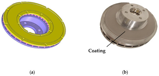
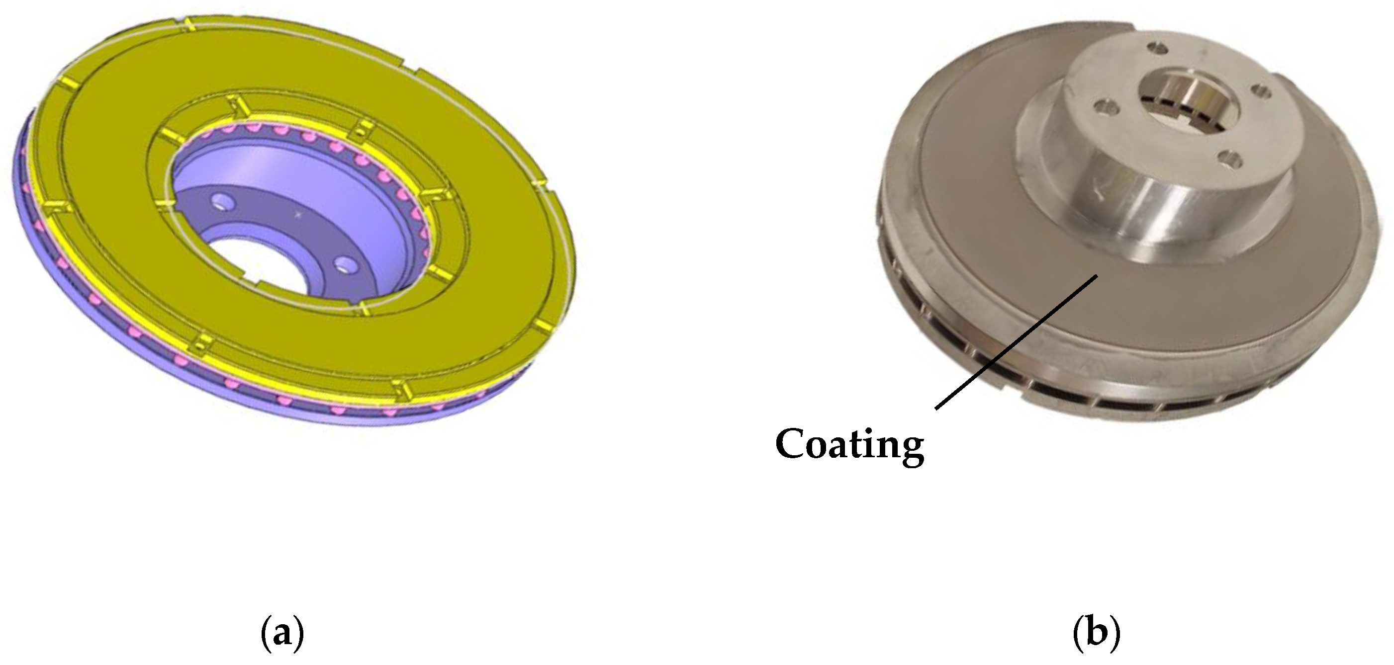
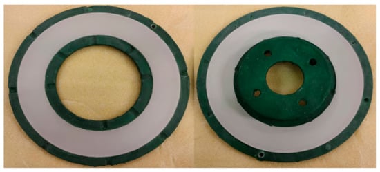
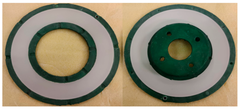
The prototype PEO-treated rotor used in this study was machined from wrought AA6082 billet in 3 pieces comprising two rubbing surface rings (one being integrated with the bell) bolted together with a separate ventilation ring, as shown in Figure 1. This unique 3-piece prototype design of 286 mm outer diameter was adopted so that the vent design could easily be changed if necessary by simply machining a new ventilation ring. To allow for only the friction surfaces of the prototype rotor to be coated, the non-rubbing surface areas of the two separated friction rings were masked off by applying a Suprawax 114 layer to these surfaces as indicated in Figure 2. Both friction rings were then exposed to a high voltage PEO treatment by Keronite (Curtiss-Wright) in an environmentally safe, alkaline electrolyte that is free of Cr, heavy metals, volatile organic compounds and strong acids. The thickness of the alumina surface layer was measured by a MiniTest 650 coating thickness gauge and found to vary between 40 and 50 µm, with the thickness at the outer edges of the friction surface being somewhat greater than the average. According to Keronite (Curtiss-Wright), the coating is predominantly 70% α, γ crystalline + 30% amorphous-phase highly dense alumina with maximum porosity c.5%. The post-treatment surface roughness is typically 0.3–0.5 µm Ra and the hardness range is 1200–1600 HK0.5.
Figure 1.
Three-piece PEO brake rotor of 286 mm outer diameter: (a) CAD model, (b) image of coated rotor.
Figure 2.
Friction rings of Al brake rotor of 286 mm outer diameter masked up with green Suprawax 114 prior to PEO processing.
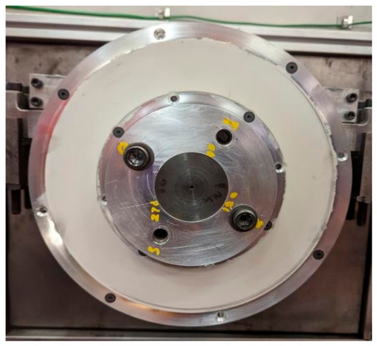
After PEO processing, the friction surfaces were cleaned and lightly abraded before the assembled 3-piece rotor was checked for axial run-out on the Leeds dynamometer. The maximum run-out was measured at no more than 0.08 mm which was considered satisfactory. Figure 3 shows the PEO rotor mounted on the Leeds dynamometer before tests. The white/grey surface on the brake rotor is the PEO coating which was only applied to the friction surfaces and not the whole brake rotor. The fact that only the rubbing surfaces of the entire rotor were PEO-treated enabled maximum convection of heat from all other untreated surfaces of the rotor, including the vents, in addition to heat conduction through to the hub-shaft mount. A previous study by Alnaqi [17] found that PEO-treating the entire brake rotor surface limits the dissipation of heat and traps it inside the rotor, potentially leading to thermal softening and even failure of the alloy substrate.
Figure 3.
PEO-coated Al brake rotor of 286 mm outer diameter mounted on brake dynamometer.
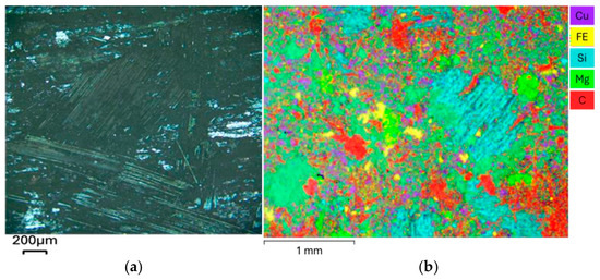
Since no commercial pad materials were available for the PEO-treated rotor, the braking tests were carried out using bespoke pads still available in the aftermarket for the Lotus Elise S1 sports car, which was originally fitted with Al-MMC brake rotors. These pads incorporate a special glass-fibre reinforced formulation which has been specifically developed to work against an Al-based rotor. Figure 4 shows a microscopy image and an energy-dispersive X-ray spectroscopy (EDS) map of the surface of the pad material, whilst Table 1 lists the percentage by weight of the key elements found. Both carbon and oxygen were evident in the brake pad; however, these elements are not quantified due to their low atomic number and also the fact that the microscopy samples are carbon-coated, leading to erroneous results. It can be seen from Table 1 that, with around 10%wt Cu, the pads are certainly not Cu-free as currently required in certain markets; the relatively high percentages of Ba and Si indicate the presence of abrasive particles and glass fibres, respectively.
Figure 4.
Brake pad surface: (a) optical microscope image, (b) EDS map.
Table 1.
Elemental composition of the aftermarket commercial brake pad obtained from EDS.
2.2. Test Equipment
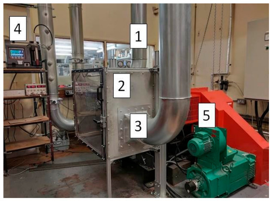
The Leeds brake dynamometer is a purpose-built device designed to measure the thermal performance and wear emissions of full-sized passenger car brakes. A 45 kW DC motor is used to drive the brake rotor at speeds up to 1500 rpm. The rotor is housed within an air-tight enclosure to enable particle emission measurements; see Figure 5. The brake pads are contained within a bespoke 4-piston brake calliper, designed to suppress brake squeal [21]. K-type thermocouples are used to measure rotor surface temperature at different points on the free rubbing surface of the rotor. High-efficiency HEPA (H14) filters are used to supply clean air into the enclosure which reduces the risk of contamination from the laboratory. The cylindrical ducting pipes are made from galvanised steel sheets and have an internal diameter of 225 mm. A 4 kW fan is used to control the airflow velocity within the ducting from 6 to 15 m/s as measured by an anemometer in the outlet duct.
Figure 5.
Brake dynamometer general arrangement: (1) Inlet duct. (2) Enclosure. (3) Outlet duct. (4) Dekati ELPI+. (5) 45 kW motor.
The particle number and mass distribution in the extracted air are measured in real time using a 14-stage Dekati ELPI+ impactor with 14 aerodynamic particle size ranging from 10 µm down to 6 nm [22]. Sanuddin [23] conducted a computational fluid dynamics (CFD) analysis of airflow through the dynamometer ducting system, including the sampling probe used to extract air containing particulate matter from the outlet duct. Based on the CFD results, the Dekati vacuum pump volume rate and the probe geometry were designed to provide isokinetic sampling conditions. Note that the ducting and air sampling system was designed before the GTR-24 standard protocol [1] was published and so does not precisely follow these requirements.
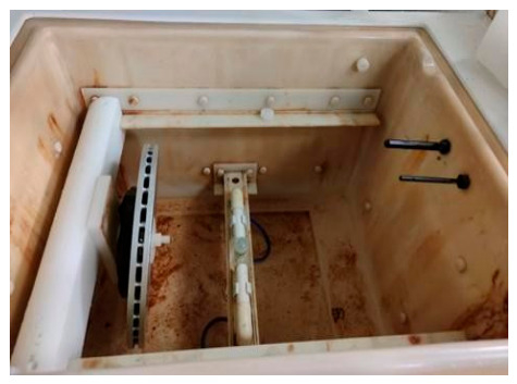
The salt spray cabinet (C&W type SF100) shown in Figure 6 contains a single atomised tower from which the salt solution is sprayed. A custom-made holder is used to mount the brake rotor in the cabinet. The holder enables the brake rotor to be placed at an angle of ±15° from the vertical axis to allow for the salt solution to run off so there is no stagnant salt solution on the brake rotor surfaces.
Figure 6.
Salt spray chamber showing brake rotor held at 15 degrees to vertical.
2.3. Test Protocol
Steady-state drag braking under conditions of constant rotating speed and constant hydraulic pressure supplied to the calliper pistons is used for all dynamometer testing. Drag braking simulates the vehicle maintaining a constant speed on a long downhill gradient during which near steady-state temperature conditions are achieved. Although this drag braking cycle differs from the Worldwide harmonised Light vehicle Test Procedure (WLTP) stipulated in the new Euro 7 regulations [1], it was adopted partly due to the non-inertial nature of the current Leeds dynamometer but also to enable comparative tests to be conducted under near steady-state tribological conditions of constant sliding speed, normal contact force and surface temperature. A typical drag braking test lasts around 90 min during which time the speed and hydraulic pressure are controlled at the set level and the braking torque and disc surface temperature are continuously recorded by a LabView data acquisition system. The instantaneous CoF of the brake is calculated from the measured torque and applied pressure assuming an effective mean friction radius, taken to be the mean radius of the pad/rotor contact patch.
For this investigation, only the brake rotor is subjected to corrosion whilst the pads remain in their uncorroded condition. The corrosion test protocol follows the ASTM B117-11 standard [24] which specifies a controlled corrosive environment for a range of coated and uncoated materials. The salt solution is prepared by dissolving 5 parts mass of pure sodium chloride in 95 parts of water. The pH of the atomised salt solution is within the 6.5 to 7.2 range. The salt spray cabinet is used to maintain steady-state conditions at a temperature of 35 ± 2 °C with a relative humidity of 95%. The brake rotor is placed in the salt spray cabinet as shown in Figure 5, where it is exposed to a corrosive environment for 96 h. The brake rotor is reversed within the cabinet after 48 h to encourage a uniform corrosion deposition on both sides of the rotor. The brake rotor hub (“top-hat”) is masked off, thus protecting it from the environment as it would be if attached to the wheel of the vehicle. Also, the steel screws used to secure the three-piece rotor together were replaced with nylon screws to stop any corrosion contamination from the metallic screws. After the brake rotor has undergone 96 h in the salt spray cabinet, it is taken out and left to air dry in normal laboratory atmospheric conditions before recommencing the dynamometer testing.
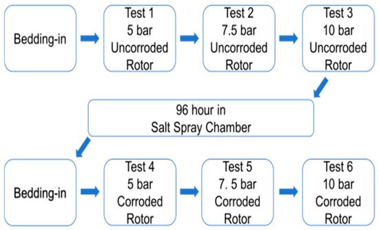
The complete test protocol is broken down into seven stages as shown in Figure 7. The bedding in cycle was based on industry recommendations for bedding-in new brake pads and rotors and consisted of 30 constant pressure brake stops followed by 10 heat cycles from 30 °C to 100 °C. The same bedding-in process is repeated after the salt bath exposure to ensure that loose corrosion products are removed from the rotor surface before the constant pressure braking cycles are repeated.
Figure 7.
Overall sequence of testing.
The actual brake tests consist of three repeat drag brake applications at each of 5, 7.5 and 10 bar hydraulic line pressure and a constant dynamometer speed of 150 rpm. No braking pressure is applied for the first 600 s of each drag braking cycle to allow for the airflow to become stable and to generate data for background particle measurement. Each circa 90 min drag braking event is followed by a 5 min cool-down period where no hydraulic pressure is applied to ensure that wear particles not released from the contact interface under braking conditions can be included in the Dekati measurement.
After the brake rotor is subjected to the salt spray treatment for 96 h, the corroded brake rotor and original pads undergo the same sequence of constant pressure brake tests. At the end of the 3 repeat tests at each applied pressure for both the corroded and uncorroded conditions, the pads are removed from the calliper and their weight is recorded in grams to two decimal places and dimensional wear is measured using a micrometre with a resolution of 0.01 mm in line with the SAE J2986 standard procedure [25].
3. Results
3.1. Braking Dynamometer Tests
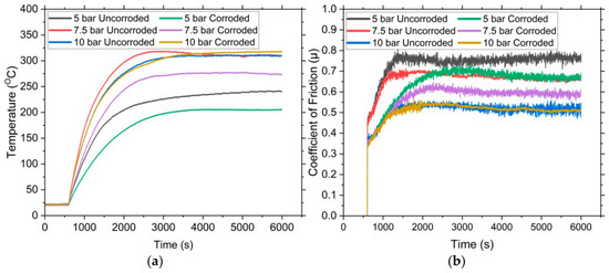
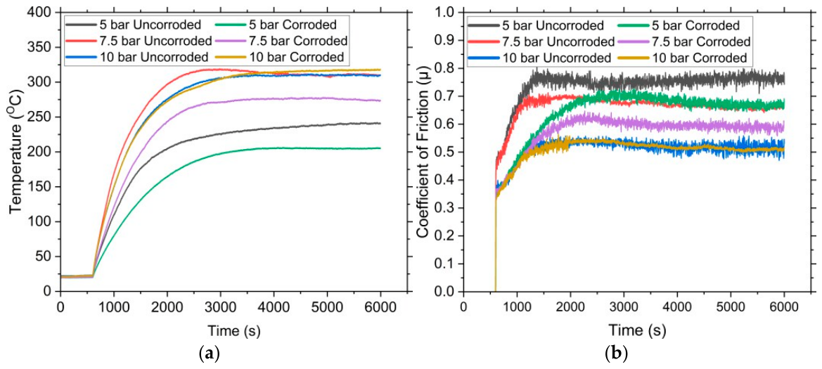
Figure 8 shows typical time histories of surface temperature and coefficient of friction respectively over the full duration of the test at each pressure for the PEO-treated brake rotor in both uncorroded and corroded conditions. It can be seen that both the steady-state temperature and CoF reach a near steady-state value after about 2000 s into the test. Figure 8a shows that the surface temperature for both uncorroded and corroded conditions increases as the brake line pressure is increased, as would be expected. The steady-state surface temperature is significantly lower for the corroded rotor tests at 5 bar and 7.5 bar, whereas at 10 bar there is much less difference between the uncorroded and corroded surface temperatures.
Figure 8.
Typical dynamometer time history results for uncorroded and corroded PEO surface at 5, 7.5 and 10 bar brake line pressure: (a) rotor surface temperature, (b) coefficient of friction.
Figure 8b shows that the steady-state CoF decreases with increasing line pressure for both the uncorroded and corroded conditions and that the corroded surface produces noticeably lower CoF during the 5 and 7.5 bar tests. However, at 10 bar, the steady-state CoF is very similar at a value of about 0.5 for both uncorroded and corroded rotor surfaces. Together with the similar surface temperatures under 10 bar pressure loading, this suggests that the corroded friction surface has returned to near its pre-corrosion condition after the relatively short braking duty cycles at the lower pressures.
3.2. Surface Analysis
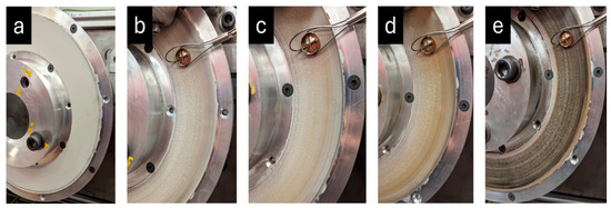
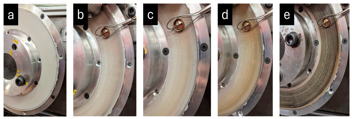
Figure 9 shows optical images of the uncorroded PEO rotor at different stages throughout the braking tests. Figure 9a shows the white virgin PEO surface whilst Figure 9b shows that the friction surface of the rotor has darkened somewhat during bedding in, which indicates that transfer of material from the brake pad to the rotor has started to form a tribolayer on the rubbing surface. As the pressure is increased from 5 to 7.5 bar and then to 10 bar, Figure 9c, Figure 9d and Figure 9e, respectively, the friction ring becomes darker and the tribolayer more apparent. The increase in the degree of darkening near the outer circumference of the PEO-treated area could be due to the small differences in coating thickness as measured by the MiniTest 650 coating thickness gauge in this region.
Figure 9.
Optical images of uncorroded rotor: (a) new brake rotor, (b) after bedding in, (c) after 5 bar, (d) after 7.5 bar and (e) after 10 bar brake pressure cycles.
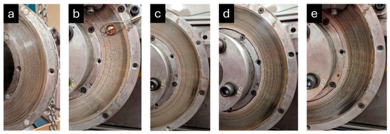
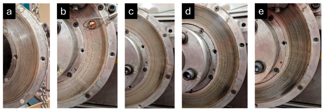
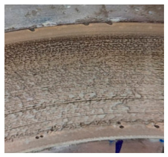
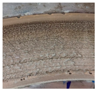
Figure 10 shows optical images of the PEO friction ring after it was subjected to 96 h in the salt spray chamber. Before subsequent brake testing, Figure 10a, the corroded PEO rotor appears to have dried salt crystals on its surface and the colour of the friction ring changes from black (due to the previously developed transfer layer) to a brownish-grey. However, both the crystals and discolouration are quickly removed during the bedding-in procedure, as seen in Figure 10b. During the subsequent drag brake test cycles, the surface of the corroded PEO rotor appears to become smoother and more homogeneous, as shown in Figure 10c,d. The surface of the friction ring at the end of the 10 bar test, Figure 10e, appears similar to that at the end of the uncorroded test, adding weight to the argument that the friction surface has returned to its original pre-corrosion condition. Despite this promising result, dark spots can be seen in Figure 10e near the edges of the friction surface, possibly indicating corrosion pitting. Such defects can be more clearly seen in the larger-scale image of one of these pitted regions, as shown in Figure 11.
Figure 10.
Optical images of corroded rotor: (a) after 96 h in the salt spray chamber, (b) after bedding in, (c) after 5 bar, (d) after 7.5 bar and (e) after 10 bar brake pressure cycles.
Figure 11.
Enlarged image of corroded PEO rotor showing defects near inner edge of friction ring.
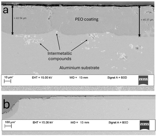
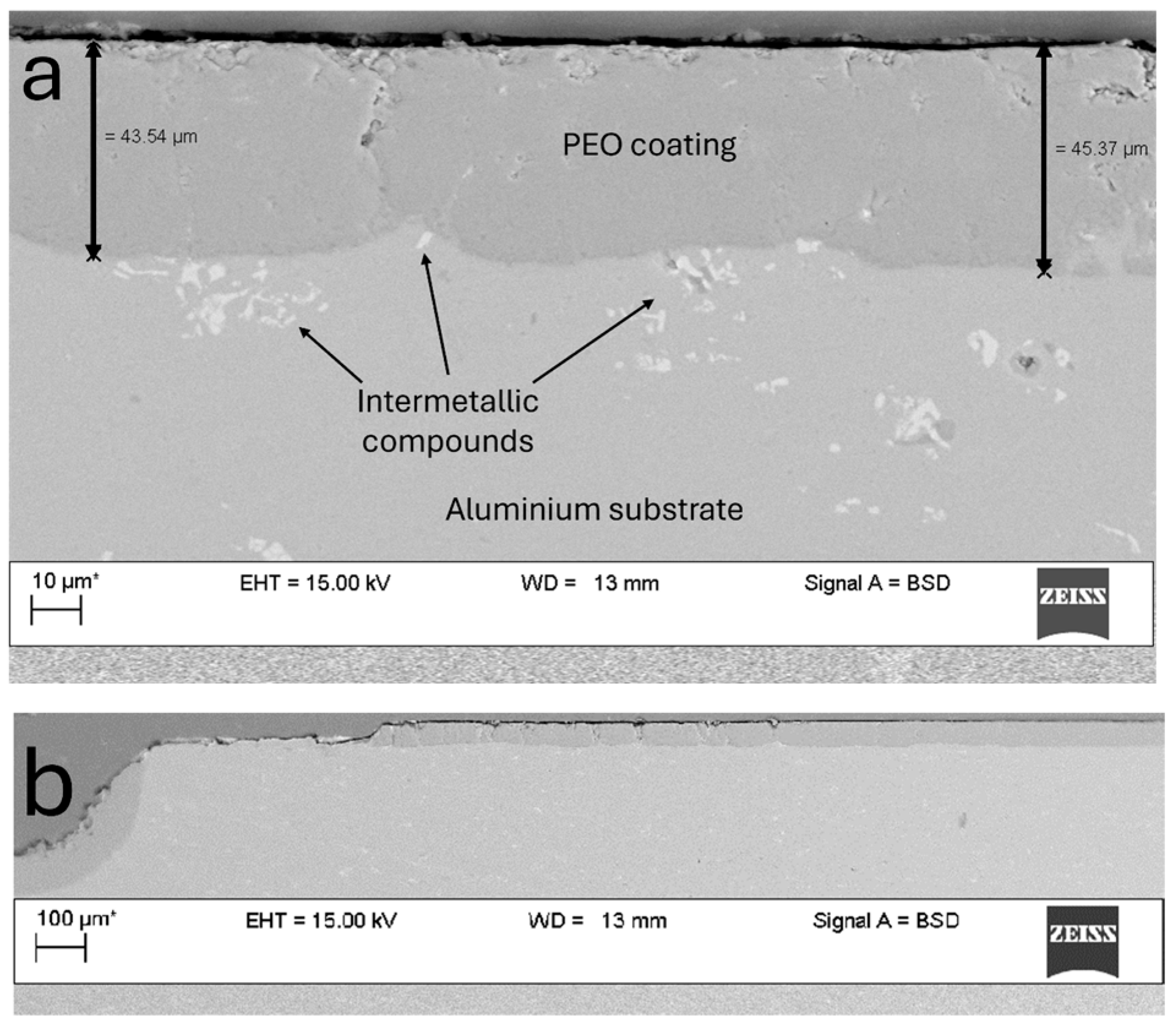
At the end of the final 10 bar brake tests on the corroded rotor, one of the friction surfaces was sectioned and subjected to SEM examination. Figure 12a shows a cross-section near the centre of the PEO rubbing surface after it had undergone the full brake and corrosion test protocol. It can be seen that the coating thickness is still around 45 µm, the same as before testing, indicating low wear, good adhesion and structural integrity. The intermetallic compounds in the AA6082 alloy shown in Figure 12a are thought to have affected the growth of the PEO coating, causing the somewhat uneven interface with the substrate. A cross-section taken from the outer edge of the friction ring where a potential corrosion pit is located is shown in Figure 12b. It can be seen that a small area of the coating has delaminated locally and the substrate material is exposed. Such areas of delamination and pitting are only located at the very edges of the coated friction ring where the PEO process will be less effective in adhering to the substrate due to proximity of the masking wax used to prevent coating of the surrounding edges of the friction surface.
Figure 12.
SEM images of sectioned corroded PEO rotor after 10 bar drag brake testing: (a) rubbing surface of the rotor showing intact PEO coating, (b) delamination at the edge of the coated region.
3.3. Wear Measurements
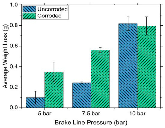
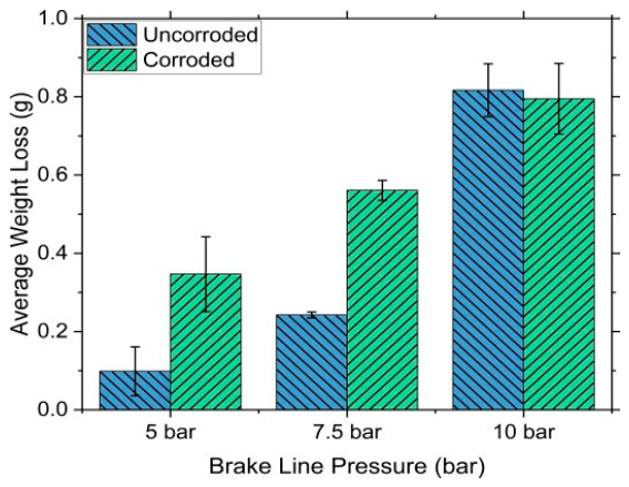
The average gravimetric wear loss of the brake pads at each brake line pressure for both uncorroded and corroded rotor conditions is shown in Figure 13 where the error bars represent the range of the results for the inboard and outboard pads. It can be seen that the pad weight loss increases with increasing brake line pressure for both uncorroded and corroded surfaces, as would be expected. At the lower brake line pressures of 5 and 7.5 bar, the corroded PEO surface produced greater pad mass loss than the uncorroded surface under identical test conditions. However, at 10 bar pressure, pad wear loss measurements for both corroded and uncorroded surfaces are very similar. This is further indication that, by the time of the 10 bar tests, the corroded PEO surface has returned to something like its precorroded condition.
Figure 13.
Gravimetric wear loss of brake pads at 5, 7.5 and 10 bar brake line pressure for uncorroded and corroded PEO rotor.
3.4. Particle Emissions
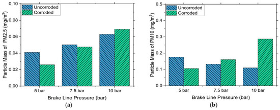
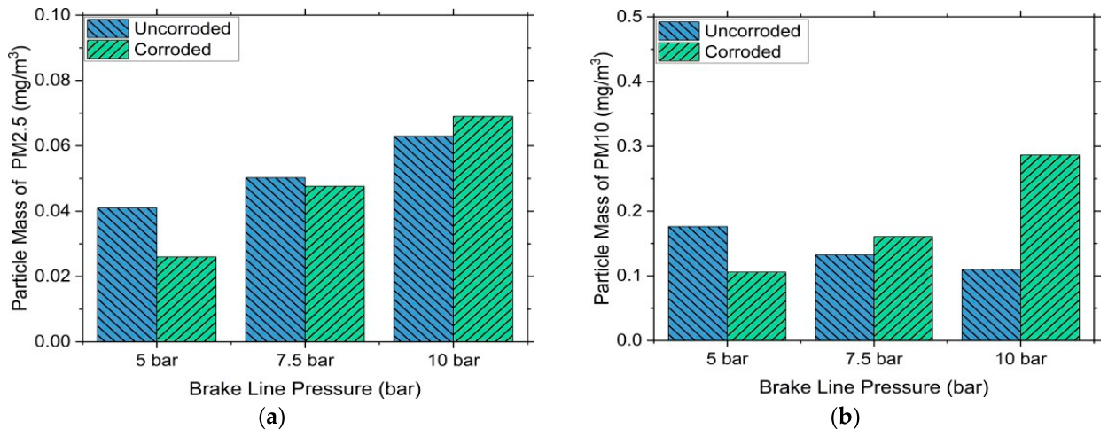
The PM2.5 and PM10 gravimetric particle wear emissions measured by the Dekati during the steady-state period 2000 s to 6000 s after the start of each test are presented in Figure 14a and Figure 14b, respectively. There are no error bars shown on any of these PM histogram plots because the weight gain on the Dekati foils was only measured for the final repeat test at each pressure. These PM measurements were orders of magnitude greater than the corresponding background readings from the clean lab air passing over the brake before pressure was applied so there was no need to subtract these very small background values from the measurements during braking.
Figure 14.
Gravimetric particulate emissions at 5, 7.5 and 10 bar brake line pressure for uncorroded and corroded PEO surfaces: (a) PM2.5, (b) PM10.
It can be seen from Figure 14a that the corroded surface generated somewhat lower PM2.5 emissions at the 5 bar pressure whereas the emissions at 7.5 and 10 bar were very similar for corroded and uncorroded conditions. Figure 14b shows that the trend was similar for PM10 emissions at pressures of 5 and 7.5 bar. However, under a pressure loading of 10 bar, the PM10 emissions were significantly higher (by a factor of about 2.5) for the corroded surface. It is possible that this high-pressure brake test removed the final remaining corrosion products from the PEO friction surface, leading to a higher PM10 value.
It should be emphasised that results from these constant hydraulic pressure and rotating speed drag brake tests are not representative of emission testing under the WLTP brake test cycle stipulated under GTR-24 [1]. Therefore, these results cannot be used for demonstrating Euro 7 compliance as has been attempted by, for example, Currie et al. [26] who did employ the standard WLTP braking cycle and GTR-24 methodology in their small-scale tests. However, the present results do allow a valid comparison of emission rates under steady-state tribological conditions before and after corrosion, as well as a comparison with emissions from alternative rotor surfaces tested under identical drag braking conditions (see Section 3.5 below).
3.5. Comparison with Corresponding Results for GCI and MMC Brake Rotors
A similar study using an identical test protocol was carried out by Ghouri [14] to investigate the effects of corrosion on a 30% SiC reinforced Al6082 MMC rotor paired with the same aftermarket friction material as used on the PEO rotor. Results were also compared with an uncoated GCI brake rotor paired with an industry-standard low-metallic friction material as currently used on most road vehicles in Europe. Although hard-coated GCI rotors have recently been introduced on new models of passenger cars to meet Euro 7 emission limits, the vast majority of road vehicles will continue to rely on uncoated GCI rotors for many years to come. Such an uncoated GCI rotor paired with an industry-standard pad material is therefore considered to provide a valid benchmark for comparison with the alternative lightweight rotors considered in this paper. Emissions from a laser-clad GCI rotor surface have been considered by Currie et al. [26] but without considering the effects of corrosion on such a surface.
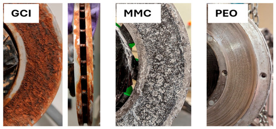
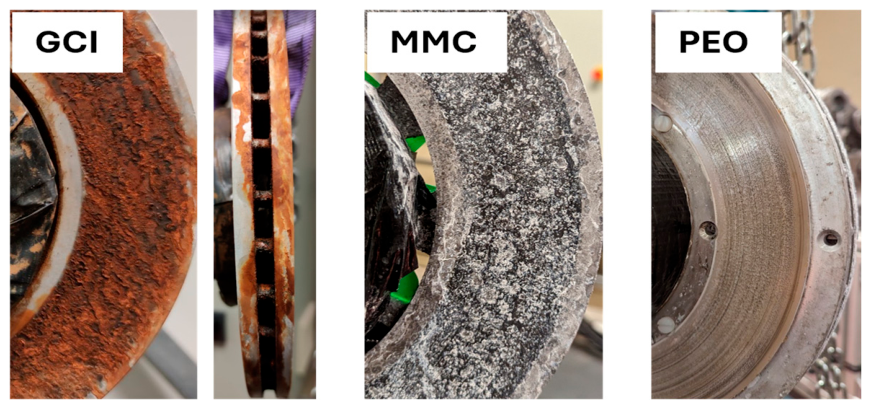
Figure 15 shows the surface appearance of the three rotors immediately after 96 h in the salt spray corrosion solution. Significant rust build-up on the GCI surface is apparent and the MMC rotor also appears to have suffered severe surface corrosion. In contrast, the rubbing surface of the PEO rotor appears largely unaffected by the corrosion cycle as noted above.
Figure 15.
Images of GCI, MMC and PEO rotors immediately after 96 h in the salt spray chamber.
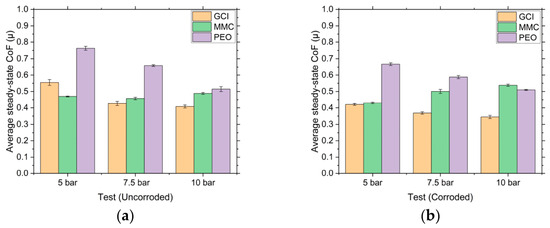
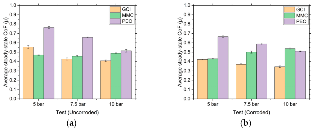
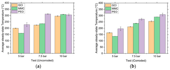
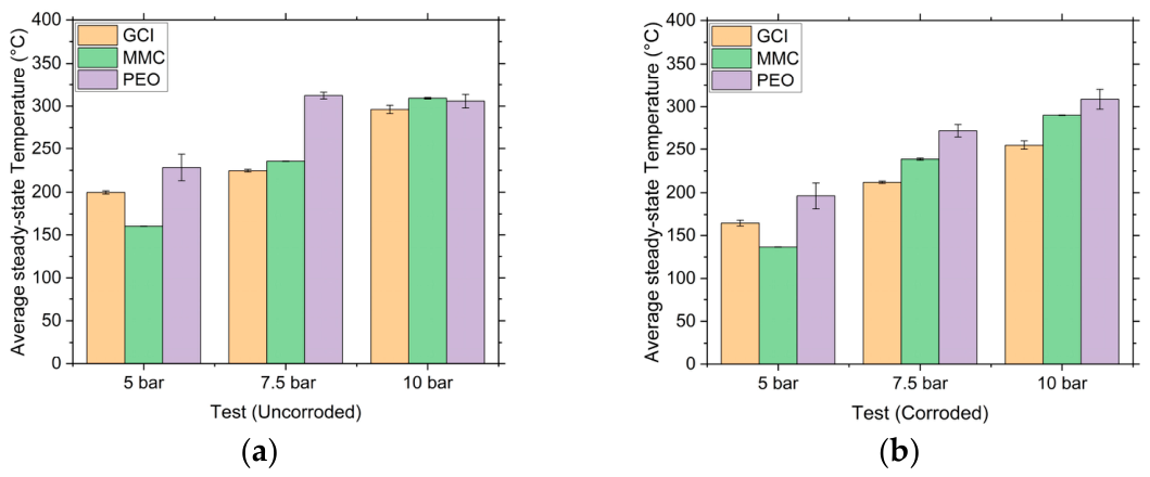
Figure 16 shows the average steady-state CoF for the three rotors as a function of pressure before and after the corrosion exposure. It can be seen that the PEO rotor tends to produce the highest CoF, especially in the uncorroded condition. This increased CoF is also reflected in the higher rotor surface temperatures shown for the PEO rotor in Figure 17 although these temperatures may also have increased due to the thermal barrier effect of the PEO layer.
Figure 16.
Steady-state coefficient of friction of GCI, Al-MMC and Al-PEO brake rotors (a) before corrosion and (b) after corrosion.
Figure 17.
Steady-state surface temperature of GCI, MMC and PEO brake rotors (a) before corrosion and (b) after corrosion.
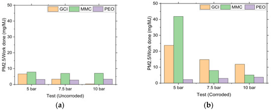
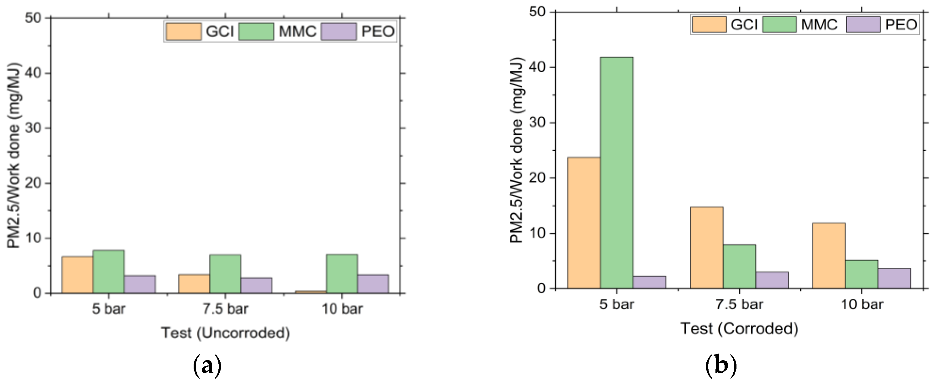
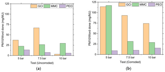
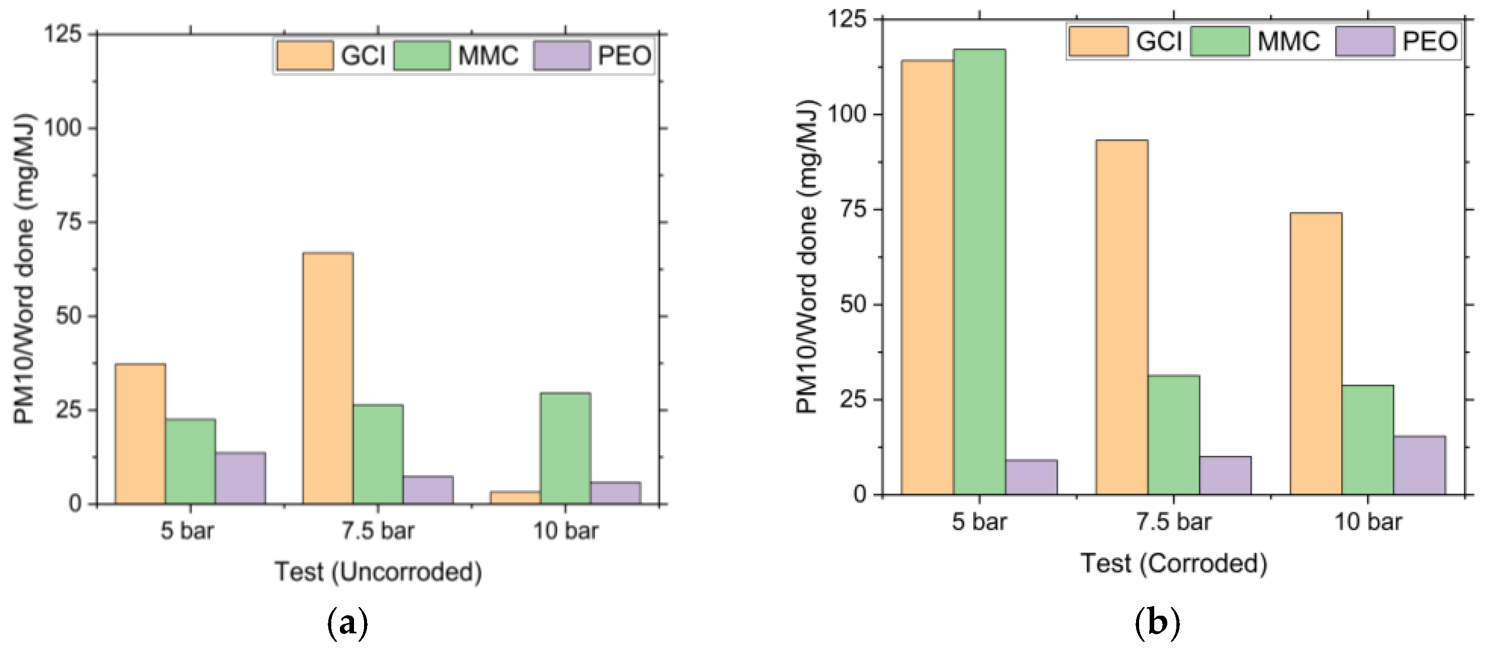
Figure 16 shows that the steady-state CoF values were quite different for the three rotor materials, both before and after corrosion. The fact that the applied pressures and rotating speed were the same for all three rotors whilst the CoF was different means that the frictional power during each test was different. To make a valid comparison between the emission results for the different rotors, the Dekati results were therefore divided by the total frictional work done in the steady-state period of about 60 min during which emissions were measured. These normalised results in terms of the estimated total emissions from each rotor in mg divided by the frictional work done in MJ before and after corrosion are shown in Figure 18 and Figure 19 for PM2.5 and PM10 emissions, respectively.
Figure 18.
PM2.5 particle emissions per unit work done for GCI, MMC and PEO brake rotors (a) before corrosion and (b) after corrosion.
Figure 19.
PM10 particle emissions per unit work done for GCI, MMC and PEO brake rotors (a) before corrosion and (b) after corrosion.
Figure 18 shows that there was a very significant increase in PM2.5 emissions post-corrosion for both the GCI and MMC rotors. An even more dramatic increase in the larger PM10 size range for the corroded GCI rotor can be seen in Figure 19. Both PM2.5 and PM10 emissions from the uncorroded PEO rotor were lower than those from the other two rotors except at the highest pressure of 10 bar where the GCI rotor gave the lowest result. The low emissions from an uncorroded GCI surface at relatively high contact pressures have previously been noted [23]. These results again demonstrate the potential of the PEO treatment to provide a much more corrosion-resistant surface and therefore to significantly reduce emissions over the lifetime of a vehicle operating in an environment where corrosion effects can occur.
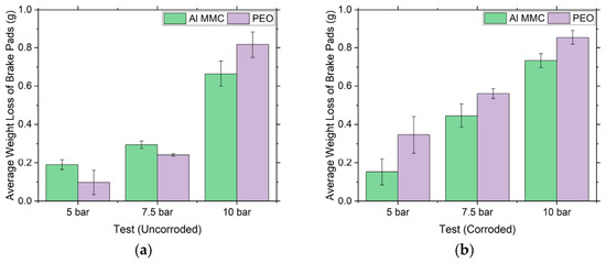
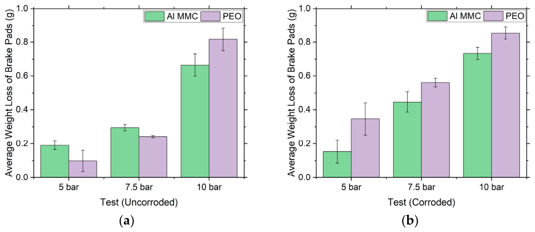
Finally, it is worth comparing the measured gravimetric wear of the brake pads for the PEO and MMC rotors since an identical pad material formulation was used for both lightweight rotors. Figure 20 shows that the wear rates were very similar for the two rotors across all braking conditions. The fact that there was not a very large increase in pad wear following corrosion is an indication that most of the significantly increased wear emissions for the corroded MMC rotor came from the rotor surface itself and not from the pads.
Figure 20.
Gravimetric wear loss of pads for MMC and PEO brake rotors (a) before corrosion and (b) after corrosion.
4. Discussion
After about 2000 s of drag brake testing on a full-scale braking dynamometer, the PEO rotor attained a maximum steady-state surface temperature of around 300 °C while the steady-state CoF varied between 0.5 and 0.8. Sanuddin [23] carried out similar tests on an Al-PEO rotor and measured similar CoF and surface temperatures. Generally, a CoF in excess of 0.5 is somewhat higher than would be desirable for a normal road passenger vehicle. However, it should be remembered that the aftermarket pad material used for these tests is designed for an Al-MMC brake rotor and therefore not optimised for the PEO surface.
After bedding in, the surface of the uncorroded PEO rotor changed progressively during the increasing pressure drag brake tests from its initial white colour to a glossy black. This colour change is a positive indication that a stable tribolayer has formed on the friction surface due to a transfer of material from the pad to the rotor. Gulden et al. [16] reported similar dark discolouration on the surface of a PEO-coated brake rotor after braking tests, assumed to due to the transfer of brake pad material. They also found that an increase in brake pressure and surface temperature increased the rate of development of this tribolayer on the PEO rubbing surface [16].
After the first complete sequence of drag pressure testing, the prototype PEO rotor was subjected to a salt spray corrosive environment for 96 h. Although this corrosion exposure removed much of the previously formed transfer layer, there was little evidence of remaining corrosion products or of any obvious surface damage over the majority of the PEO surface. A corrosion test was also performed by Shrestha et al. [15] after dynamometer testing of a PEO-treated Al alloy rotor at both 300 °C and 400 °C initial brake temperature (IBT). They found that the 300 °C IBT-tested rotor showed negligible corrosion effects with just a few spots of white rust. However, after the 400 °C IBT test, more obvious corrosion effects were apparent which were thought to be due to the brake rotor suffering thermal crazing during these more severe braking cycles leading to cracks in the PEO coating. These cracks created pathways for the salt solution to penetrate deep into the coating and to cause damage to the substrate [15].
Since the rotor temperatures in the present tests did not exceed 300 °C, no such thermal crazing or cracks in the PEO surface were observed. However, a small number of corrosion “pits” and delaminations were found near the edges of the PEO-treated rubbing surface. Gulden et al. [16] reported similar defects after their PEO-coated rotor was subjected to a similar corrosion test. A measurement was carried out to determine the depth of these defects and it was found that they extended into the substrate material.
The occurrence of similar pits and delaminations around the inner and outer edges of the rubbing surface of the present rotor could be attributed to the incomplete nature of the coating process in these regions. The PEO treatment was only applied on the friction surface and not over the entire rotor. A special wax treatment was used to mask the untreated areas but it was difficult to apply this uniformly to the narrow inner and outer edges of the rubbing surfaces. Hence, these edges were not uniformly PEO-treated, resulting in a more porous and variable-thickness alumina layer in these locations. This porous layer would have afforded less protection against the corrosive salt solution, allowing pits and delaminations to form near the edges of the PEO friction surface. It should be emphasised that the majority of the PEO friction surface throughout each uncorroded and corroded braking test remained smooth and had a polished shine to it with no obvious signs of surface damage.
It was found that the corroded PEO-Al rotor generally produced lower surface temperatures and CoF but increased pad wear compared with its uncorroded counterpart. However, the brake wear emissions did not significantly increase after corrosion except for PM10 particles at the highest pressure of 10 bar. Compared with an identical series of tests with a standard GCI rotor, the uncorroded PEO-Al rotor generally produced lower particle mass emissions than the uncorroded GCI rotor, except at 10 bar applied pressure. A similar reduction in PM emissions for both wrought and cast PEO-treated Al surfaces in comparison with uncoated GCI was found in small-scale tribometer testing using the WLTP braking cycle but no account was taken of the potential effects of corrosion [26]. In the present full-size tests, the corroded PEO-Al rotor produced much lower PM10 and PM2.5 emissions, by a factor of over 3, compared with the corroded GCI under all brake line pressure tests. These results suggest the potential benefits of the PEO-Al rotor in terms of its greater corrosion resistance as well as its lightweight compared with the standard GCI.
The results from the PEO rotor were also compared with another lightweight alternative, a 30% SiC-reinforced Al-MMC rotor of similar size and weight, which was subjected to the same braking and corrosion cycles using the same pad material formulation. Again the PEO rotor produced significantly lower emissions under all braking conditions but especially after corrosion when there was a large increase in emissions from the MMC rotor which can be attributed to corrosion of the exposed alloy substrate leading to surface disruption and the accelerated release of wear particles. The fact that the measured wear of the pads was similar for both PEO and MMC rotors is evidence that most of these additional airborne particles originated from the disrupted MMC rotor surface rather than the brake pads themselves.
Although the aftermarket friction material used in these tests was not specifically designed to be paired with an alumina surface, it was found to be compatible with the PEO rotor which was not visibly damaged during these tests at temperatures up to 300 °C. However, it is recommended that the friction material should be further optimised as it developed relatively high levels of friction against the PEO surface. Also, the pad’s chemical composition should be refined, as it currently contains high levels of copper and other harmful elements which are banned in certain regions of the world.
Finally, the pitting and delamination damage seen near the outer edges of the PEO friction ring following the corrosion exposure is clearly an issue worthy of further investigation. It is quite likely that a move towards hard tooling to mask off the regions of the rotor not required to undergo PEO treatment would alleviate this problem by providing a clean boundary between the treated and untreated regions. However, the effectiveness and practicality of this hard tooling approach (which would be necessary for any series production) has yet to be investigated.
5. Conclusions
The rubbing surfaces of a prototype Al alloy rotor were successfully PEO-treated to form a c.50 µm thick alumina coating. The coated rotor was found to generate stable CoF and to withstand surface temperatures in excess of 300 °C over a range of typical drag braking conditions when paired with a commercially available aftermarket pad material. A severe corrosion cycle of 96 h in a salt spray chamber produced no significant changes either to the appearance of the PEO rubbing surface or to the braking performance. Pad wear was somewhat increased at the lower braking pressures following corrosion but PM emissions were largely unaffected except at the highest pressure of 10 bar when a significant increase in PM10 mass was recorded post-corrosion. At the end of the braking tests on the corroded rotor, small pit-like defects and delaminations were found at the very edges only of the PEO rubbing area.
Results for the PEO rotor were compared with those for an uncoated GCI rotor rubbing against a low-metallic friction material which is the current industry-standard pairing. Surface temperatures and CoF were somewhat higher for the PEO rotor both before and after corrosion. However, PM emissions were significantly lower for the PEO rotor, especially after the corrosion cycle when the GCI rotor suffered serious surface disruption due to excessive rust formation.
Comparisons were also made between the results for the PEO rotor and an Al-MMC rotor subject to the same braking and corrosion cycles and using the exact same aftermarket friction material. Surface temperatures and CoF were somewhat higher but emissions significantly again lower for the PEO rotor, especially after corrosion. The fact that the pad wear was similar for the two Al rotors, both before and after corrosion, suggests that the reduced emissions for the PEO rotor were mainly due to the hard and corrosion-resistant nature of the alumina surface layer compared with that of the MMC surface where the Al alloy matrix was exposed to wear and corrosion effects.
Overall, the results presented in this paper demonstrate the potential of a lightweight PEO-treated Al rotor not only to produce satisfactory braking performance but also to significantly reduce PM emissions, even after exposure to severe corrosion conditions.
Author Contributions
Conceptualisation, D.C.B., R.B. and S.S.; methodology, D.C.B., R.B., I.G. and S.S.; investigation, I.G.; resources, D.C.B., R.B. and S.S.; data curation, I.G.; writing—original draft preparation, D.C.B.; writing—review and editing, D.C.B., R.B., I.G. and S.S.; visualisation, I.G.; supervision, D.C.B., R.B. and S.S.; project administration, D.C.B. All authors have read and agreed to the published version of the manuscript.
Funding
This research received no external funding.
Data Availability Statement
Details of the results are available from the first named author (I.G.).
Acknowledgments
The first named author (I.G.) would like to thank the UK Engineering and Physical Science Research Council (EPSRC) for funding his PhD studentship.
Conflicts of Interest
Author Suman Shrestha was employed by the company Keronite International Ltd. The remaining authors declare that the research was conducted in the absence of any commercial or financial relationships that could be construed as a potential conflict of interest.
Abbreviations
The following abbreviations are used in this manuscript:
| CoF | Coefficient of Friction |
| EDS | Energy-Dispersive X-ray Spectroscopy |
| GCI | Grey Cast Iron |
| HVOF | High-Velocity Oxygen Fuelled |
| IBT | Initial Brake Temperature |
| LCA | Life Cycle Assessment |
| MMC | Metal Matrix Composite |
| NEE | Non-Exhaust Emissions |
| PEO | Plasma Electrolytic Oxidation |
| PM | Particulate Matter |
| SEM | Scanning Electron Microscopy |
| WLTP | Worldwide Harmonised Light Vehicle Test Procedure |
References
- European Commission. Proposal for a Regulation of the European Parliament and of the Council on Type-Approval of Motor Vehicles and Engines and of Systems, Components and Separate Technical Units Intended for Such Vehicles, with Respect to Their Emissions and Battery Durability (Euro 7); European Commission: Brussels, Belgium, 2022. [Google Scholar]
- Van Der Gon, H.D.; Hulskotte, J.; Jozwicka, M.; Kranenburg, R.; Kuenen, J.; Visschedijk, A. European emission inventories and projections for road transport non-exhaust emissions: Analysis of consistency and gaps in emission inventories from EU member states. In Non-Exhaust Emissions; Elsevier: Amsterdam, The Netherlands, 2018; pp. 101–121. [Google Scholar]
- Riediker, M.; Devlin, R.B.; Griggs, T.R.; Herbst, M.C.; Bromberg, P.A.; Williams, R.W.; Cascio, W.E. Cardiovascular effects in patrol officers are associated with fine particulate matter from brake wear and engine emissions. Part. Fibre Toxicol. 2004, 1, 2. [Google Scholar] [CrossRef] [Scilit] [PubMed]
- Peikertova, P.; Filip, P. Influence of the automotive brake wear debris on the environment-a review of recent research. SAE Int. J. Mater. Manuf. 2016, 9, 133–146. [Google Scholar] [CrossRef] [Scilit]
- Aranke, O.; Algenaid, W.; Awe, S.; Joshi, S. Coatings for automotive gray cast iron brake discs: A review. Coatings 2019, 9, 552. [Google Scholar] [CrossRef] [Scilit]
- Cai, R.; Zhang, J.; Nie, X.; Tjong, J.; Matthews, D. Wear mechanism evolution on brake discs for reduced wear and particulate emissions. Wear 2020, 452, 203283. [Google Scholar] [CrossRef] [Scilit]
- Hesse, D.; Hamatschek, C.; Augsburg, K.; Weigelt, T.; Prahst, A.; Gramstat, S. Testing of alternative disc brakes and friction materials regarding brake wear particle emissions and temperature behavior. Atmosphere 2021, 12, 436. [Google Scholar] [CrossRef] [Scilit]
- Menapace, C.; Mancini, A.; Federici, M.; Straffelini, G.; Gialanella, S. Characterization of airborne wear debris produced by brake pads pressed against HVOF-coated discs. Friction 2020, 8, 421–432. [Google Scholar] [CrossRef] [Scilit]
- Lyu, Y.; Leonardi, M.; Mancini, A.; Wahlström, J.; Olofsson, U. Tribology and airborne paricle emission of laser-cladded Fe-based coains versus non-asbestos oranic and low-metallic brake materials. Metals 2021, 11, 1703. [Google Scholar]
- Zhang, H.; Ma, X.; Tao, W. Microstructure and tribological behavoiur of exteme high-speed laser-cladded TiC coatings on gray cast iron brake disks. J. Them. Spray Technol. 2025, 34, 3294–3307. [Google Scholar]
- Ahmad, F.; Lo, S.J.; Aslam, M.; Haziq, A. Tribology behaviour of alumina particles reinforced aluminium matrix composites and brake disc materials. Procedia Eng. 2013, 68, 674–680. [Google Scholar] [CrossRef] [Scilit]
- Oda, N.; Sugimoto, Y.; Higuchi, T.; Minesita, K. Development of disk brake rotor utilizing aluminum metal matrix composite. In International Congress & Exposition; SAE Technical Paper; SAE International: Warrendale, PA, USA, 1997. [Google Scholar] [CrossRef] [Scilit] [PubMed]
- Wycliffe, P. Friction and wear of duralcan reinforced aluminum composites in automotive braking systems. In International Congress and Exposition; SAE Technical Paper; SAE International: Warrendale, PA, USA, 1993. [Google Scholar] [CrossRef] [Scilit]
- Ghouri, I.; Barker, R.; Brooks, P.C.; Barton, D. Particle emissions from an aluminium metal matrix composite brake otor before and after corrosion. In EuroBrake 2023 Conference Proceedings; Paper No. EB2023-TST-006; FISITA: Barcelona, Spain, 2023. [Google Scholar]
- Shrestha, S.; Francis, R.; Smith, A. RELIABLE: Wear Resistent Lightweight Alummiun Brakes for Veicles. In EuroBrake 2020 Conference Proceedings; Paper No. EB2021-EBS-032; FISITA: Barcelona, Spain, 2020. [Google Scholar]
- Gulden, F.; Reinhold, B.; Gramstat, S.; Stich, A.; Tetzlaff, U.; Höppel, H. Investigation of the run-in and corrosion behavior of a PEO-coated aluminum brake disc. In Proceedings of the 10th International Munich Chassis Symposium 2019; Springer: Berlin/Heidelberg, Germany, 2019; pp. 611–631. [Google Scholar]
- Alnaqi, A.A. Characterisation of Coated Lightweight Brake Rotors. Ph.D. Thesis, University of Leeds, Leeds, UK, 2014. [Google Scholar]
- Olofsson, U.; Lyu, Y.; Åström, A.H.; Wahlström, J.; Dizdar, S.; Nogueira, A.P.G.; Gialanella, S. Laser cladding treatment for refurbishing disc brake rotors: Environmental and tribological analysis. Tribol. Lett. 2021, 69, 57. [Google Scholar] [CrossRef] [Scilit]
- Gradin, K.T.; Åström, A.H. Comparative life cycle assessment of car disc brake systems—Case study results and method discussion about comparative LCAs. Int. J. Life Cycle Assess. 2020, 25, 350–362. [Google Scholar] [CrossRef] [Scilit]
- Currie, M. Comparative Life Cycle Assessment of Novel Environmentally Friendly Brake Rotors. Ph.D. Thesis, University of Leeds, Leeds, UK, 2025. [Google Scholar]
- Budinsky, T. Towards the Active Suppression of Disc Brake Squeal. Ph.D. Thesis, University of Leeds, Leeds, UK, 2018. [Google Scholar]
- Dekati. Dekati® ELPI + User Manual; Dekati: Kangasala, Finland, 2016. [Google Scholar]
- Sanuddin, A.B. Particulate Wear Debris of Coated Lightweight Brake Discs. Ph.D. Thesis, University of Leeds, Leeds, UK, 2020. [Google Scholar]
- ASTM B117-11; Standard for Operating Salt Spray (Fog) Apparatus. ASTM International: West Conshohocken, PA, USA, 2011.
- SAE J2986; Brake Pads, Lining, Disc, and Drum Wear Measurements. SAE International: Warrendale, PA, USA, 2019.
- Currie, M.; Limmer, F.; Huang, Y.; Gilkeson, C.A.; Barton, D.C. Friction performance and wear emissions of coated and uncoated brake rotor materials. Lubricants 2026, 14, 123. [Google Scholar] [CrossRef] [Scilit]

Disclaimer/Publisher’s Note: The statements, opinions and data contained in all publications are solely those of the individual author(s) and contributor(s) and not of MDPI and/or the editor(s). MDPI and/or the editor(s) disclaim responsibility for any injury to people or property resulting from any ideas, methods, instructions or products referred to in the content. |
© 2026 by the authors. Licensee MDPI, Basel, Switzerland. This article is an open access article distributed under the terms and conditions of the Creative Commons Attribution (CC BY) license.