


Abstract
The extreme environment characterized by repeated freeze–thaw cycles poses a severe challenge to the stability and durability of loess in engineering applications. This study systematically investigates the improvement of Weinan loess using a plant-based bio-cement (BC) combined with fly ash (FA) under extreme freeze–thaw environments. Through unconfined compressive strength tests, permeability tests, calcium carbonate content measurements, and microscopic analyses (SEM and XRD), the mechanical properties, microstructural evolution, and crack development characteristics of the improved loess were comprehensively evaluated. The results demonstrate that BC-FA modification significantly enhances the mechanical strength and impermeability of loess. The unconfined compressive strength of the 7% FA-amended specimen increased by 201.6% compared to untreated loess, while the permeability coefficient decreased by 61.58%. Freeze–thaw-induced deterioration predominantly occurred within the first five cycles, with a maximum peak strength reduction of 33.29%, after which the soil structure gradually stabilized beyond ten cycles. Microscopic observations revealed that biomineralized calcium carbonate crystals (calcite, aragonite, and vaterite) filled pores and bridged soil particles, forming a continuous cementation network. Furthermore, a novel Crack Identification Method Based on Multi-Feature Mechanical Responses (CIMBMFMR) was proposed, which establishes a quantitative mapping between mechanical degradation, micro-damage, and crack evolution, offering superior accuracy and physical interpretability over traditional image-based techniques. The BC-FA system exhibits notable low-carbon and eco-friendly advantages, providing a promising green solution for loess reinforcement in seasonally frozen regions.
1. Introduction
Extreme climatic environments, represented by repeated freeze–thaw cycles and wet–dry alternations, continuously weaken the cementation structure of loess through the physical phase transition and chemical erosion of pore water, leading to a significant deterioration of its mechanical properties. Loess is primarily distributed in arid and semi-arid regions worldwide, including Asia, Africa, Central and Southern Europe, Antarctica, the northwestern United States, northern Russia, inland Alaska, and South America [1]. China boasts the most extensive distribution of loess worldwide, covering an area of approximately 6.4 × 10⁵ km2. Loess is a unique sediment formed during the Quaternary period, composed of a mixture of clay, silt, and sand particles, with silt particles typically constituting over 70% [2]. The particles are mostly bonded together by secondary calcium carbonate and clay. The specific particle size distribution and interparticle connections endow loess with high strength under dry conditions [3]. However, loess is highly sensitive to water; the ingress of moisture into its pores can lead to a weakening of cementing strength [4]. Moreover, the high porosity ratio of loess provides the conditions for the variability of its structure. Indeed, the infiltration of water is often the primary trigger for geotechnical engineering disasters in loess regions, which have already impacted people’s lives and the stability of infrastructure [5,6]. Due to the instability of loess, it is necessary to improve its strength for engineering construction in loess areas. Current methods for loess improvement include “physical improvement” and “chemical improvement” [7,8,9,10,11]. Physical improvement involves artificial compaction methods such as dynamic compaction and rolling to increase the dry density of the soil, thereby enhancing the strength of loess to meet the required mechanical specifications [12,13,14]. Meanwhile, chemical improvement by adding agents to loess to increase its mechanical strength is also used in practical engineering. Among the various agents, cement and lime have become the main additives due to their low cost and high efficiency [15,16]. However, further research has revealed that when cement is added to soil, its strength is affected by the working environment; when the environment changes, the shear strength of the cement–soil decreases, it becomes more prone to cracking, and its resistance to deformation worsens. The use of lime and cement also has certain environmental impacts, such as carbonation, sulfate attack, and the production of greenhouse gases, which are contrary to global environmental policies [17,18]. Therefore, there is an urgent need for a new set of technologies for loess improvement that are gentle, cost-effective, adaptable, and pollution-free and have significant short-term ecological restoration effects.
Currently, a method of improvement that is garnering attention from researchers is bio-cement improvement technology. This technology encompasses microbial-induced calcium carbonate precipitation (MICP) and plant-based bio-cement (BC) solidification techniques. The MICP technique is a biomineralization process that induces the formation and deposition of carbonate minerals through microbial activity, which has broad applications for reinforcing and sealing tiny pores and cracks in rock masses. However, its drawback is that urease-producing bacteria are susceptible to environmental factors, leading to instability in the amount of urease secreted and the efficiency of mineralization [19]. On the other hand, BC solidification technology is another efficient, green, and low-cost new environmental protection technology. It is primarily based on plant-based urease directly catalyzing the hydrolysis of urea to produce carbonate ions, which combine with introduced calcium ions to precipitate cementitious calcium carbonate crystals, thereby achieving solidification [20,21]. The plant-based urease mineralization process does not involve living organisms nor does it pose biological safety concerns; thus, it is not affected by the specific cellular processes or metabolic rates of microorganisms, facilitating large-scale field applications. Urease is easily soluble in water, has low viscosity, and possesses good fluidity akin to water, which is conducive to the uniform precipitation of calcium carbonate [22]. Compared to the MICP technique, BC has a wider range of applications and is more suitable for the repair and treatment of rock masses, showing good application effects in the reinforcement of sandy soil materials.
At present, there is very little research on the improvement of loess with BC, and it is not yet clear what the reinforcement effect of BC mineralization on loess is, nor the patterns of change in its mechanical characteristics before and after mineralization, or the changes in microstructure. In light of this, it is very necessary to conduct research on the mechanism of BC reinforcement of loess. This work will employ laboratory experiments combined with various testing and analysis methods to develop a solidification strategy for BC-improved loess, quantitatively analyze the influence patterns of key mechanical parameters and seepage characteristics of loess before and after improvement, and reveal the mechanism of BC solidification of loess. The expected research can provide theoretical support and a scientific basis for the engineering practice of this method, offering a new method and technology for improving loess.
2. Field Investigation of Engineering Distresses and Failures
Focusing on the loess-covered areas of Shaanxi Province, 20 typical loess engineering disease cases were selected from seven cities—Yan’an, Yulin, Xi’an, Xianyang, Weinan, Baoji, and Tongchuan. Through field surveys, data monitoring, and statistical analysis, the distribution patterns, core characteristics, and causal mechanisms of the diseases were systematically examined, providing an accurate empirical basis for loess engineering disease prevention and control as well as engineering performance enhancement.
2.1. Distribution Characteristics of Disease Cases
The 20 disease cases exhibited pronounced regional clustering in their geographical distribution (Table 1): 8 cases in Yan’an, concentrated in loess ridge-and-hill areas and around scenic sites, with slope angles of 38–65°; 4 cases in Yulin, distributed across northern loess tablelands and mining areas, with slope heights of 15–30 m; and the remaining 8 cases scattered across five cities including Xi’an, spanning tableland margins, river terraces, and scenic areas, with an elevation range of 450–1200 m. Landslides and collapses were the dominant disease types (Table 1): seven landslides (35%), predominantly occurring on “upper soil–lower rock” slopes of 35–55°, with volumes of 120–8500 m3; five collapses (25%), concentrated in areas of dense vertical joints, with masses of 20–350 t; one gully and one crack (each 5%), with gully depth 1.2–3.5 m, length 20–80 m, crack width 0.5–2.8 mm, and extension 5–30 m; and six other types (30%), including slope erosion and retaining wall failure.
Table 1.
The disease types.
2.2. Core Characteristics and Development Dynamics of Diseases
Disease development exhibited salient common features: 90% were concentrated in the rainy season from June to October, with slope instability readily triggered when cumulative 3-day rainfall exceeded 180 mm, and maximum hourly rainfall intensity of a single storm reached 60 mm/h; 20% were affected by freeze–thaw action, with 35–45 annual freeze–thaw cycles and a frost heave force of 0.4–0.6 MPa; 65% developed in an “upper soil–lower rock” double-layer structure, where the upper Q2/Q3 loess featured dense vertical joints spaced 0.3–1.0 m apart, and the underlying bedrock softened upon water exposure; 30% occurred on free faces with slopes exceeding 35°, and slope heights generally of 10–35 m; and 70% were associated with human activities, involving various disturbances such as slope-top irrigation leakage and engineering excavation.
Development dynamics displayed type-specific differentiation: landslides followed three stages of “initial creep → accelerated deformation → instability failure”, with displacement rates < 0.5 mm/d in the initial stage, increasing to 2–5 mm/d in the accelerated stage, and sliding distances of 1.2–85 m at instability; collapses exhibited a “latency → sudden failure” pattern, with only localized surface spalling in the latent stage and no discernible early warning before triggering, with instantaneous collapse velocities reaching 3–8 m/s; and gullies and slope erosion were dominated by slow cumulative damage, with gully expansion rates of 0.5–2 m/yr and slope erosion thickness of 0.5–1 cm/yr. Water served as the key accelerator for all disease types, raising soil saturation from 35% to 90% and reducing shear strength by 40%–57%, while human activities shortened the landslide incubation period from several years to several months.
2.3. Disease Cause Mechanism
Disease occurrence resulted from the coupling of natural and anthropogenic factors. Natural factors constituted the intrinsic basis: loess porosity of 40%–55% and dense vertical joints; Grade II collapsible loess in certain areas (collapsibility coefficient 0.05–0.07); and montmorillonite content in paleosol layers of 15%–18%, with a water-induced swelling rate of 7%–8%, all compounded by rainstorm events (short-duration rainfall intensity 60 mm/h, maximum cumulative continuous rainfall 185 mm), freeze–thaw cycles (frost heave force 0.4–0.6 MPa, volumetric expansion of pore water upon freezing 9%), and the unfavorable “upper soil–lower rock” terrain—the underlying strongly weathered bedrock, 2–3 m thick, formed a weak sliding surface upon water softening, readily inducing slope instability. Anthropogenic factors constituted significant triggers: substandard design parameters (anti-slide pile spacing of 5 m, micropile verticality deviation of 1.5% (specification requirement ≤ 1%), gabion mesh wire diameter of 2.7 mm (specification requirement ≥ 3.4 mm)); inappropriate selection of anti-corrosion and anti-freeze materials (anchor rods without epoxy coating + PE sleeve, concrete without air-entraining agent, frost resistance grade F150 below the specified F200); construction quality defects (fill compaction degree of 90%, grouting pressure of 0.5 MPa below the required 1 MPa); and lack of post-construction maintenance (intercepting ditch joint leakage rate of 15%, annual terrace ridge collapse rate > 30%), all directly inducing or aggravating the diseases.
2.4. Disaster Consequences and Investigation Significance
The disaster consequences exhibited multi-layered superposition characteristics: the maximum direct economic loss from a single disaster reached 8 million yuan (dump slope instability at Boluo Town coal mine, Hengshan District, Yulin), with an average loss per case exceeding 1 million yuan, involving farmland damage (maximum 15 mu), road emergency repair (maximum single-section damage of 150 m, repair cost of 0.95 million yuan), and enterprise shutdown (maximum shutdown duration of 14 days, affecting 150,000 tons of output); 12 cases threatened residential safety, with a maximum of 32 persons evacuated in a single event; 5 cases affected transportation and water conservancy facilities, damaging an irrigation canal up to 120 m in length; and ecological problems were also induced, including 40 mu of wetland degradation in Qianyang County, Baoji, and a 40% increase in soil and water loss in Yijun County, Tongchuan.
The sensitive strata and key disaster-causing factors identified through the above disease investigation directly guided the experimental design of subsequent laboratory and microscopic tests: targeted remolding and improvement tests were carried out to systematically evaluate the macroscopic performance of different mix-ratio modifiers in enhancing the erosion resistance and moisture-absorption resistance of loess; simultaneously, microscopic tests such as X-ray diffraction and scanning electron microscopy were conducted to verify, from both compositional and structural dimensions, the reaction products and cementation-filling effects between the modifier and the loess matrix, thereby providing core parameters and an optimal pathway for constructing a mechanism-based disease prevention and control system and achieving targeted engineering performance enhancement.
3. Materials and Methods
3.1. Preparation of Urease
In this experiment, urease was prepared from soybeans purchased from Shaanxi Province. The basic composition of the soybeans is shown in Table 2.
Table 2.
Basic components of soybean.
The urease solution was primarily obtained using a crude extraction method: First, the soybeans were ground into powder using a grinder and sieved, and an appropriate amount of the soybean powder was mixed with tap water and stirred for half an hour. The soybean solution was then placed into centrifuge tubes and centrifuged at 2600 r/min for 20 min. After standing for a period of time, the supernatant extracted was the soybean urease solution. The study considered the influence of various factors such as reaction temperature, environmental pH, and solution concentration on the urease. The variations of these factors are presented in Table 3.
Table 3.
Factors affecting urease.
3.2. Loess Samples and Test Plan
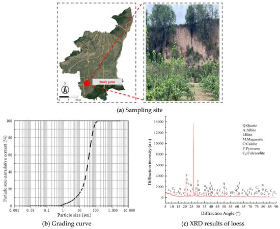
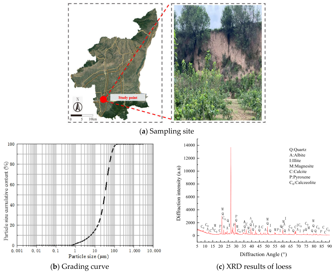
This study focuses solely on the loess from Weinan City, Shaanxi Province, which was obtained from a slope in Weinan City through exploratory pit sampling. After manual excavation to form the pit, the excavation proceeded gradually to a depth of about 3 m, where samples were taken by slowly digging from the sidewall into the pit. The samples are from the shallow surface layer of Q3 loess, as shown in Figure 1a.
Figure 1.
Sampling points and basic characteristics of Weinan loess.
After retrieval, the soil was sieved to obtain the gradation curve, as depicted in Figure 1b. Additionally, X-ray polycrystalline diffraction experiments were conducted to determine the composition of the plain loess (as shown in Figure 1c), which mainly includes albite, quartz, magnesite, calcite, zeolite, pyroxene, and illite. In accordance with the “Standard for Soil Test Methods” (GB/T 50123-2019), the basic physical indicators of the loess were measured using the pycnometer method, the oven-drying method, the ring knife method, and the liquid-plastic limit apparatus. The test results are presented in Table 4.
Table 4.
Physical and mechanical properties of Weinan loess.
3.3. Macroscopic Test Method
In this paper, the macroscopic experiments are divided into two main parts—unconfined compressive strength tests and permeability tests—both conducted indoors.
Following the requirements of GB/T 50123-1999, the method of mixing first and then compacting was adopted. Soil samples with the same moisture content were poured into solidification molds and compacted. After solidification, the samples were trimmed to standard sizes for unconfined compressive strength tests and permeability tests. Here, the dimensions of the unconfined compressive strength test specimens were 39.1 mm in diameter and 80 mm in height; the permeability test specimens were 61.8 mm in diameter and 40 mm in height.
- (1)
- Unconfined Compressive Strength Test Before and After Freeze–Thaw Cycles
To prepare the unconfined compressive strength test specimens, BC was uniformly mixed with loess at a certain moisture content, and then loaded into the mold in 5 layers, with each layer compacted to the same height, and the contact surfaces between layers were scarified. To facilitate demolding after solidification, a small amount of Vaseline was applied to the inner wall of the mold.
After the freeze–thaw cycles, the mold was removed, and the specimens were taken out and placed on the unconfined compression tester to obtain the stress–strain curve. The loading rate of the instrument was set at 0.075 mm/min.
- (2)
- Permeability Test Before and After Freeze–Thaw Cycles
The preparation of permeability test specimens also used the method of mixing first and then compacting directly in the ring knife. A small amount of Vaseline was applied to the inner wall of the ring knife, and the mold was loaded in three layers, with each layer compacted to the same height, and the contact surfaces between layers were scarified. According to the “Standard for Soil Test Methods GB/T 50123-2019”, the variable head method was used to test the permeability of the specimens, and the calculation Formula (1) is as follows:
where is the fracture area of the variable head tube, cm2; is the specimen area, cm2; is the seepage path, here refers to the height of the sample, cm; t1, t2 is the measured start and end time of the water head, s; and is the start and end head, respectively.
In the experiment, five fly ash dosage gradients of 0%, 1%, 3%, 5% and 7% were set based on the mass of loess. Fly ash particles provide heterogeneous nucleation sites for calcium carbonate to promote the uniform precipitation of mineralized products and optimize the cementation structure of soil. The bio-cement is composed of plant-based urease (100 g/L), urea solution (1 M) and calcium chloride solution (1 M), and the urease, urea and calcium chloride solutions are mixed at equal volumes.
It is noteworthy that field survey results indicate that the average annual temperature in the Weinan region ranges between −15 °C and 25 °C. Research has shown that freezing samples at −20 °C for 12 h can sufficiently ensure that the internal moisture is frozen, and thawing at 20 °C for 12 h can ensure the thermal melting of moisture. Meanwhile, for fine-grained soils, past experiments have demonstrated that after 6 to 8 freeze–thaw cycles, their physical and mechanical properties tend to stabilize [23]. Based on the above analysis, this paper selects the minimum and maximum temperatures for the freeze–thaw cycles as −15 °C and 25 °C, respectively, with a freezing duration of 12 h and a thawing (or insulation) duration of 12 h, making one complete freeze–thaw cycle 24 h to ensure a thorough freeze–thaw effect. The experiment sets the number of freeze–thaw cycles at 0, 5, 10, and 15 times.
3.4. Calcium Carbonate Content Determination
Given that the test soil is loess, which naturally contains a small amount of primary detrital calcium carbonate and secondary precipitated calcium carbonate, and that the experiment adopts a sample preparation method of mixing first followed by compaction, the dosages of urease and cementing solution are limited. As a result, the amount of newly formed calcium carbonate through biomineralization is relatively small. Therefore, when the acid washing method is used to determine the calcium carbonate content in the solidified loess, it is difficult to effectively distinguish between the indigenous carbonate background of the loess and the newly formed carbonate, leading to considerable quantitative errors. Consequently, this method is not applicable. To accurately analyze the actual amount of calcium carbonate generated inside the solidified loess specimens prepared by the mixing method, this study adopts the weighing method for quantitative determination.
The specific procedure is as follows: Before the test, 30 g of dry loess for solidification in each group is uniformly weighed and recorded as the initial mass W0. After the curing period, the specimens are placed in an oven at 105 °C for 24 h until constant mass is reached, cooled, and then weighed, with the mass recorded as Ws. The difference between the two weighings (Ws − W0) represents the mass of calcium carbonate generated through biomineralization during the solidification process, and the calculation is shown in Equation (2).
This method can directly eliminate the interference of the native calcium carbonate background in loess and accurately reflect the relative differences in calcium carbonate yield under varying fly ash dosages.
3.5. Microscopic Test Method
- (1)
- Scanning electron microscopy (SEM)
Scanning electron microscope (Zeiss Gemini360, CARL ZEISS, Oberkochen, Germany) was used to observe the microstructure of BC-treated loess samples and untreated loess samples at different magnifications. The samples were dried in an oven at 60 °C before scanning.
- (2)
- X-ray polycrystalline diffraction experiment (XRD)
For X-ray diffraction (XRD), an X-ray diffractometer (Bruker-D8Advance, Bruker, Karlsruhe, Germany) was used to observe the microstructure of BC-treated loess samples and untreated loess samples. The samples were dried in an oven at 60 °C before scanning. The diffraction angle range is 5–90°, and the scanning speed is 5°/min.
4. Results and Discussion
4.1. Macroscopic Mechanical Properties
- (1)
- Unconfined compressive strength
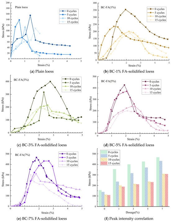
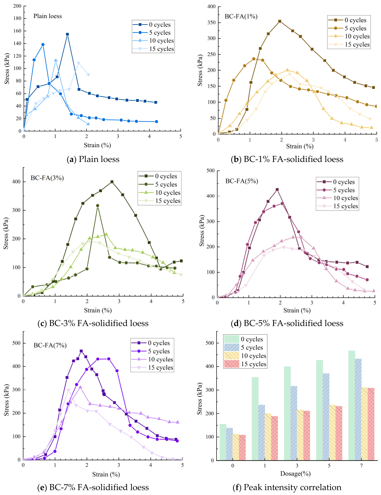
The unconfined compressive strength results of loess before and after BC-FA improvement under different freeze–thaw cycle conditions are shown in Figure 2.
Figure 2.
Comparison of peak intensity with different dosage and different cycle times.
Compared to the unconfined compressive strength of plain loess in Figure 2a, the stress–strain curves of the improved soil exhibit significantly higher peak values, and all show a transition from gentle to sharp and then back to gentle, indicating that the failure mode of the loess samples when using BC-FA is a plastic failure mode. The unconfined compressive strength of the untreated and non-freeze–thaw-cycled loess sample is 154.8 kPa, while the unconfined compressive strength of the improved sample without freeze–thaw cycles is higher than that of the untreated sample. For example, the sample with a 7% additive content shows an increase of 201.6% compared to plain loess.
However, relative to plain loess, the stress–strain curves of the samples using BC-FA exhibit more serrated fluctuations as the additive content increases, which may be related to the cracks generated during uniaxial compression failure of the samples, as well as the possibility that with the increase in FA content, the samples show varying degrees of inhomogeneity under the same mixing method, leading to the weaker parts failing first and forming failure surfaces during the compression process of the uniaxial compression tester. But by comparing the peak strengths, it can be seen that the increase in additive content also significantly enhances the maximum compressive strength of the improved loess, suggesting that in practical use, it is necessary to ensure thorough and uniform mixing of the soil and the improvement agent during the mixing stage. From the stress–strain curves of samples under different additive content combinations, it can be observed that in the initial stage, the sample is in the compaction stage, and as the pores become smaller, the stress increases slowly with increasing strain. Then it enters the elastic–plastic stage, where the stress increases rapidly with increasing strain, and at this time, obvious microcracks and bulges can be observed. After the curve reaches its peak, it begins to decline, at which point the sample develops larger cracks until it is destroyed.
Under the same additive content but different numbers of freeze–thaw cycles, the peak strength of the samples shows a clear trend of first decreasing and then stabilizing as the number of freeze–thaw cycles increases, as shown in Figure 2b–e. This phenomenon can be inferred to be due to the solid–liquid phase transition of moisture during the freeze–thaw process, causing corresponding compression, destruction, and movement of soil particles in the samples, which creates conditions for the development of pores in the samples. The development and connection of pores then lead to a reduction in peak strength, and when the samples continue to be affected by axial stress, this connection and development cause fluctuations in the stress–strain curve. It is also found that the changes in the structure and properties of the samples are most drastic when freeze–thaw cycles occur at the zeroth and fifth times, such as the peak strength of the sample with a 1% additive content being 354.4 kPa at the zeroth freeze–thaw cycle and 236.4 kPa at the fifth freeze–thaw cycle.
However, as the number of freeze–thaw cycles increases, their effect on the samples gradually weakens. As can be seen from Figure 2, whether it is plain loess or the samples with additives, after more than 10 freeze–thaw cycles, the degree of peak strength attenuation decreases, such as the peak strengths of the sample with a 5% additive content being 237 kPa and 231.5 kPa after 10 freeze–thaw cycles, with an attenuation amplitude of 2.32%.
- (2)
- Modulus of deformation
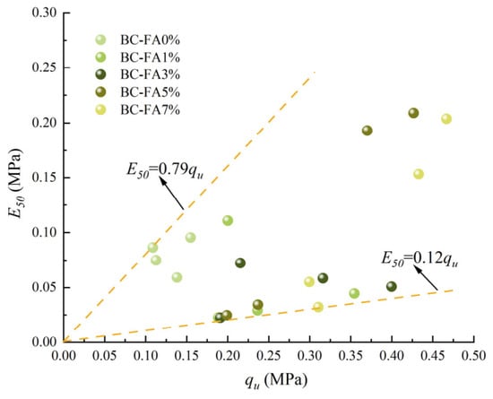
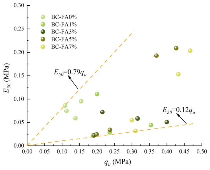
The deformation modulus is an important parameter for evaluating the deformation characteristics of geotechnical materials [24,25].
In the formula, represents the unconfined compressive strength, and corresponds to the strain at 50% of the compressive strength.
Figure 3 shows the correlation between the deformation modulus and compressive strength of the specimens before and after improvement. Generally, there is a marginal difference in the deformation modulus between the specimens before and after improvement. According to the test results, the ratio of the deformation modulus to compressive strength ranges from 0.12 to 0.79.
Figure 3.
Modulus of deformation E50.
This is due to the BC solidification process being influenced by many factors, some of which may be responsible for the differences between UCS and E50 [26,27,28]. For example, initial characteristics such as particle shape, particle size, and compactness may have a significant impact on the mechanical properties of BC-treated samples. Additionally, the generated by BC also affects the improved samples. Studies have shown that with the same content, the UCS and values of coarse-grained soil samples are much higher than those of fine-grained soil samples after improvement. The concentration of urease, urease activity, and cementing solution also significantly affect the precipitation of crystals and the improvement of the samples. Furthermore, environmental pH and temperature also influence the characteristics of crystals generated by BC.
- (3)
- Impermeability test
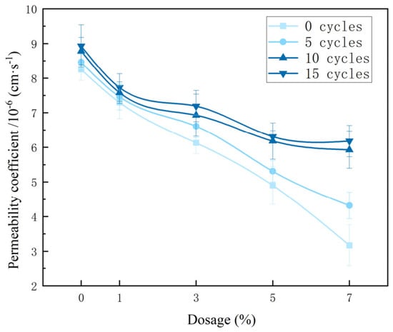
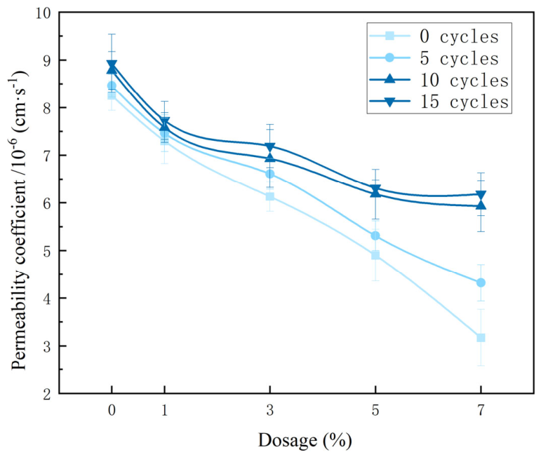
The permeability coefficients of the improved samples under different additive contents and freeze–thaw cycles are shown in Figure 4. As can be seen from the figure, the additive content of FA and the number of freeze–thaw cycles affect the permeability coefficient.
Figure 4.
Permeability coefficient of improved loess samples.
Taking the samples without freeze–thaw cycles as an example, under the same freeze–thaw cycle conditions (zero cycles), the permeability coefficient of the samples decreases with the increase in additive content. Among them, the permeability coefficient of the plain loess sample is 8.25 × 10⁻⁶ cm·s−1; when improved with BC-FA (FA content of 1%), the permeability coefficient of the loess sample is 7.3 × 10⁻⁶ cm·s−1, and the impermeability increases by 11.52%; and when the BC-FA-improved sample has an FA content of 7%, the permeability coefficient is 3.17 × 10⁻⁶ cm·s−1, and the impermeability increases by 61.58%.
Similarly, taking the freeze–thaw-cycled samples as an example, under the same freeze–thaw cycle conditions (15 cycles), the trend of the permeability coefficient change is similar to that of the samples without freeze–thaw cycles. The permeability coefficient of the plain loess sample is 8.93 × 10⁻⁶ cm·s−1, which is 8.24% lower than that of the plain loess without freeze–thaw cycles. As the FA content increases, when the BC-FA-improved sample has an FA content of 7%, the permeability coefficient is 6.18 × 10⁻⁶ cm·s−1, which is 30.79% lower than that of the plain loess without freeze–thaw cycles.
Overall, the impermeability of the improved loess samples under different additive contents and freeze–thaw cycle conditions weakens with the increase in freeze–thaw cycles. For example, when the FA content is 7%, the permeability coefficient of the sample without freeze–thaw cycles is 3.17 × 10⁻⁶ cm·s−1, after 5 freeze–thaw cycles, the permeability coefficient of the improved sample is 4.32 × 10⁻⁶ cm·s−1, after 10 freeze–thaw cycles, it is 5.93 × 10⁻⁶ cm·s−1, and after 15 freeze–thaw cycles, it is 6.18 × 10⁻⁶ cm·s−1. The trend of change with the number of freeze–thaw cycles is similar for loess samples with other additive contents (FA = 0%, 1%, 3%, 5%).
It is noteworthy that although freeze–thaw cycles affect the impermeability of the improved loess, the impact on impermeability tends to level off after 10 freeze–thaw cycles. This phenomenon is consistent with the trend of unconfined compressive strength of improved loess under the influence of freeze–thaw cycles, which is directly related to the FA added to the improved loess and the calcium carbonate crystals generated after bio-cement improvement filling the pores between loess particles.
- (4)
- Calcium carbonate content
The amount of calcium carbonate precipitation is one of the key factors in evaluating the level of BC improvement.
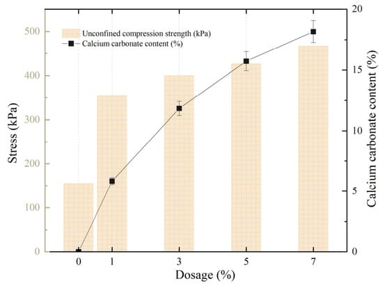
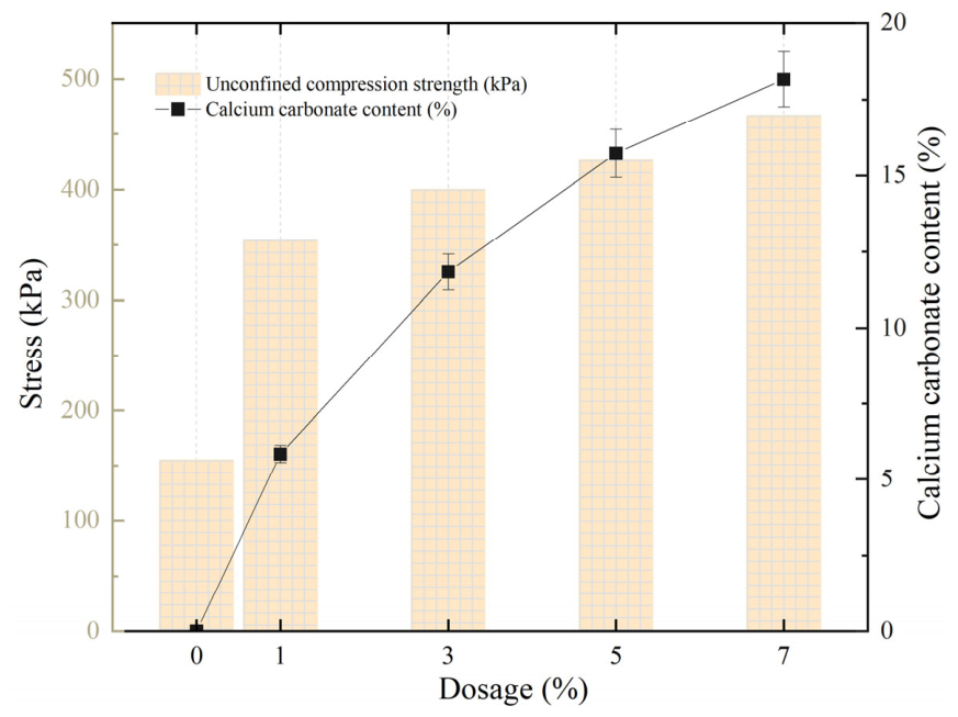
Figure 5 shows the relationship between the amount of calcium carbonate precipitation in loess before and after improvement under different additive contents and the trend of unconfined compressive strength changes. As can be seen from the figure, the pattern of change in the amount of calcium carbonate precipitation in the samples before and after improvement is similar to the pattern of change in unconfined compressive strength. The unconfined compressive strength of the samples and the amount of calcium carbonate precipitation are positively correlated with the increase in FA content, because the amount of calcium carbonate precipitation directly affects the magnitude of the unconfined compressive strength, and the calcium carbonate precipitation generated by BC is influenced by FA.
Figure 5.
The relationship between calcium carbonate precipitation and unconfined compressive strength.
4.2. Microscopic Characteristics
- (1)
- SEM
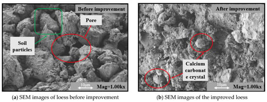
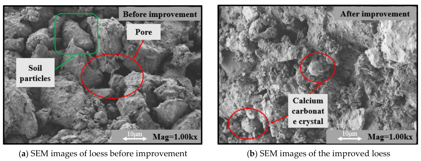
The scanning electron microscopy (SEM) images of the loess samples before and after improvement are shown in Figure 6. Based on the SEM results, the deposition and distribution of calcium carbonate crystals in the improved loess samples were analyzed. On this basis, the impact of BC on loess solidification before and after improvement was discussed.
Figure 6.
SEM images.
According to the distribution of calcium carbonate crystals, the functions of the crystals are divided into two categories: filling and cementing. Filling mainly refers to the blocking effect of calcium carbonate between loess particles, while cementing is the bridging effect built by calcium carbonate crystals between loess particles, primarily creating an accumulation between adjacent particles and forming a whole, thereby enhancing the strength of the samples.
As can be seen from Figure 6a, the pores of the unimproved loess samples are large, whereas the pores of the BC-treated samples are significantly reduced. At the same time, it can be observed that the loess improved by BC has obvious calcium carbonate crystal generation, as shown in Figure 6b. The calcium carbonate crystal particles generated in the soil are few, mainly presenting as individual small particles, isolatedly attached to the surface of soil particles or cemented between particles, with a sparse distribution. The overall strength is improved by irregular blocky calcium carbonate precipitation through filling and cementing.
- (2)
- XRD
The existing literature indicates that the crystal forms of calcium carbonate generated by BC are mostly calcite, vaterite, and aragonite, with calcite being the most thermodynamically stable and the primary form of calcium carbonate crystals generated during the BC improvement process.
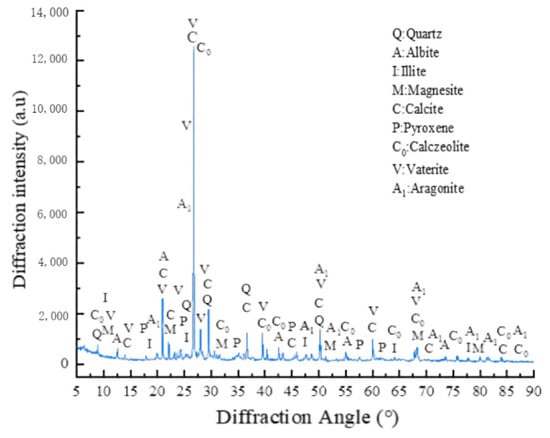
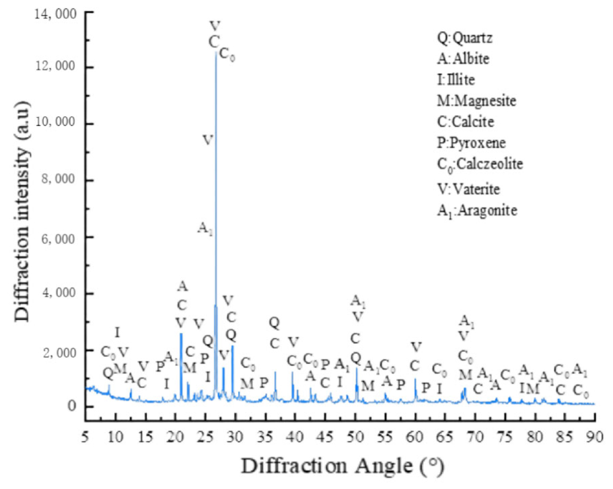
Figure 7 shows the XRD analysis results of loess samples improved by BC-FA. From the figure, it can be seen that the improved loess contains typical quartz minerals (, with characteristic diffraction peaks at 2θ = 25.875°, 28.908°, d = 3.44 nm, 3.09 nm) and albite minerals (, with characteristic diffraction peaks at 2θ = 20.577°, 27.298°, d = 4.30 nm, 3.26 nm). At the same time, it was found that the generated loess also contains other components, such as magnesite (, with characteristic diffraction peaks at 2θ = 32.637°, 43.018°, d = 2.749 nm, 2.102 nm), calcite (, with characteristic diffraction peaks at 2θ = 29.347°, 39.345°, d = 3.038 nm, 2.278 nm), pyroxene (, with characteristic diffraction peaks at 2θ = 31.007°, 36.605°, 44.360°, d = 2.887 nm, 2.452 nm, 2.239 nm), and illite (, with characteristic diffraction peaks at 2θ = 8.732°, 26.517°, d = 10.051 nm, 3.365 nm).
Figure 7.
XRD results of improved loess.
It is noteworthy that, compared to the XRD results of unimproved loess (Figure 1c), in addition to the components described above, other forms of calcium carbonate crystals have been generated, such as vaterite (, with characteristic diffraction peaks at 2θ = 24.884°, 27.10°, d = 3.575 nm, 3.29 nm) and aragonite (, with characteristic diffraction peaks at 2θ = 26.225°, 33.106°, d = 3.402 nm, 2.699 nm). This provides evidence for the improvement of loess by BC-FA. It is precisely due to the interaction of the three crystal forms of calcium carbonate with loess particles that the mechanical properties of loess are enhanced.
5. Crack Analysis
Based on the images acquired during the unconfined compressive strength test described in Section 4.1, a quantitative analysis of the dynamic evolution characteristics of cracks was conducted. During the test, a high-resolution digital camera positioned directly in front of the specimen continuously recorded the deformation process on the specimen surface at fixed time intervals (e.g., one frame per second), thereby obtaining a sequence of crack development images corresponding to each moment of the stress–strain curve. These images were imported into a digital image processing program built on MATLAB (2025b) and OpenCV libraries, and sequentially subjected to grayscale conversion, Gaussian filtering for noise reduction, background subtraction for crack enhancement, Otsu’s adaptive thresholding for binary segmentation, and morphological opening and closing operations to remove noise and connect discontinuous cracks. Subsequently, algorithms such as skeleton extraction and distance transform were employed to accurately calculate the total crack length, average crack width, and crack ratio (i.e., the ratio of crack area to total specimen area), thus achieving a transition from qualitative description to quantitative characterization of crack features.
On this basis, correlation analysis was performed between the quantified crack characteristic parameters (e.g., proportion of initial cracks and total crack length at failure) and macroscopic mechanical indices (peak strength and elastic modulus). Meanwhile, combined with X-ray diffraction (XRD) and scanning electron microscopy (SEM) microstructural test results, the underlying mechanism by which biogrout inhibits crack propagation was thoroughly elucidated.
5.1. Method for Crack Identification Based on Multi-Feature Mechanical Responses
The Crack Identification Method Based on Multi-Feature Mechanical Response (CIMBMFMR) represents a fundamentally new paradigm for material damage identification. Freeze–thaw-induced material damage is, in essence, a process of systematic deterioration of mechanical properties—a process that leaves quantifiable characteristic fingerprints in macroscopic stress–strain responses. By analyzing the evolution of these mechanical characteristic parameters, the method accomplishes a fundamental shift from “appearance-based identification” to “mechanism-based early warning.”
Traditional crack identification methods rely primarily on visual inspection or image processing techniques, which are, by nature, passive responses to cracks that have already formed. In contrast, the CIMBMFMR method possesses prospective early-warning capability. Its core innovation lies in establishing a quantitative mapping relationship of “mechanical property degradation–microscopic damage accumulation–macroscopic crack development,” enabling the accurate identification of material damage states at an early stage when cracks are not yet visible to the naked eye. The technical route of this method is grounded in multidisciplinary integration: understanding freeze–thaw damage mechanisms from the perspective of materials science, establishing constitutive relationships from the perspective of solid mechanics, and realizing feature extraction and pattern recognition from the perspective of information science. This cross-disciplinary integrated innovation enables CIMBMFMR not only to identify the current crack state, but also to predict future development trends, thereby providing decision support for preventive maintenance of engineering structures.
It is particularly worth emphasizing that the CIMBMFMR method possesses significant practical engineering value. By constructing a standardized system of characteristic parameters and clear state discrimination criteria, this method overcomes the limitations of traditional methods, such as strong subjectivity and a low degree of quantification (Table 5). Whether for the durability assessment of subgrade engineering in cold regions, freeze–thaw damage monitoring of hydraulic structures, or quality control of building materials, this method provides a reliable technical tool.
Table 5.
The comparison between CIMBMFMR and traditional methods.
- (1)
- Crack Characteristic Function
This formula serves as the input layer of the algorithm. It takes the original grayscale image of specimens with different fly ash (FA) contents captured at loading time t. α, β and γ are weight coefficients that regulate the contribution ratios of three features: macroscopic crack gradient feature , micron-scale microcrack enhancement feature , and fly ash noise reduction factor MFA. Weighted fusion outputs the crack-enhanced feature field, providing a clean image input for multi-scale segmentation in Formula (5). Differentiated preprocessing is performed on images of specimens with various mix ratios to establish independent crack identification benchmarks for each group from the source.
- (2)
- Multi-Scale Crack Detection
Pixel groups satisfying the grayscale criterion are screened out via the discriminant expression, and crack pixels of all scales are fused by taking the union set to output the complete binary crack pixel set Cmulti. This step simultaneously captures microscopic micro-damage in specimens and macroscopic through-going main cracks formed at the failure stage.
- (3)
- Physical Constraint Optimization
This constraint term embeds discriminant thresholds for loess pores and calcium carbonate crystals to filter false recognition of pores and mineral speckles. The optimal corrected crack parameter vector p is solved by minimizing the sum of the mechanical deviation term and weighted microscopic constraint term, eliminating the bias of pure image algorithms that overestimate cracks in plain loess and underestimate cracks in fly ash-modified loess.
- (4)
- Multi-Parameter Collaborative Optimization
The arithmetic average of crack width wi at all crack skeleton pixels is calculated to output the average crack width.
The percentage ratio of total crack area to the fixed area of the specimen observation window is computed to output the fracture area ratio.
The maximum value of crack width among all crack pixels is extracted to output the maximum through-going crack width.
The total geometric length of all independent crack skeletons is summed to output the total crack length.
5.2. Experimental Results and Analysis
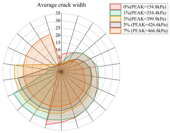
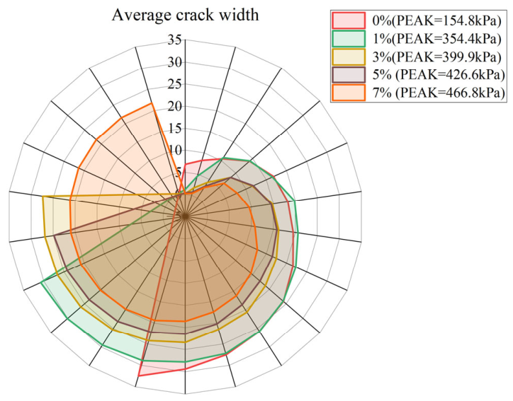
From the perspective of the full loading evolution law, the unconfined compressive strength (UCS) of all loess specimens improved with different fly ash contents continuously rises throughout the loading process, with a rapid strength growth rate at the initial stage that gradually slows down as the peak load is approached. At the same loading step, the peak strength is positively correlated with the increase of fly ash content. The ultimate UCS of plain loess (0% fly ash) is merely 154.8 kPa, while the peak strength of specimens modified with 7% fly ash reaches 466.8 kPa, demonstrating that the incorporation of fly ash can enhance the bearing capacity of soil throughout the entire loading process. In contrast, the average crack width of each group expands gradually with increasing load; under identical loading conditions, specimens with higher fly ash contents display smaller average crack widths. The average crack width of plain loess at failure reaches 32.46, whereas that of the 7% fly ash group is only 21.79 (Figure 8). Groups with low fly ash contents show a sharp increase in crack width and severe cracking, while crack development progresses gently in high-fly-ash groups, proving that fly ash exerts a prominent inhibitory effect on crack initiation and propagation.
Figure 8.
The relationship between UCS peak value and average crack width of bio-cemented loess (FA = 0%~7%).
A negative correlation exists between unconfined compressive strength and average crack width. Increasing fly ash content simultaneously improves the compressive performance of soil and mitigates crack development. The physical filling effect and active cementitious reaction of fly ash micro-particles work in tandem with the biogenic calcium carbonate cementation skeleton to redistribute internal stress. This not only drastically raises the overall bearing capacity of the soil but also restrains the expansion of internal cracks, transforming the failure mode of the soil from brittle cracking for plain loess to ductile failure for highly modified specimens. In addition, the most remarkable increments in strength and reductions in crack width occur when fly ash content increases from 0% to 3%, and the rate of performance improvement slows down once the content exceeds 3%. The fly ash content of 7% balances high compressive strength and crack control performance, which is identified as the optimal mixing proportion range.
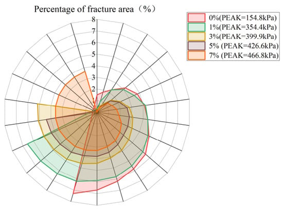
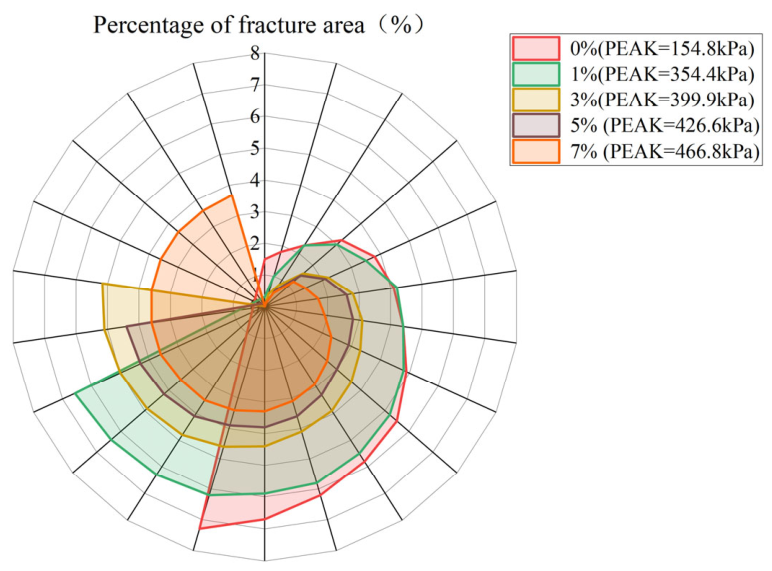
As shown in Figure 9, the percentage of fracture area of specimens in each group increases continuously with the rising load. Under identical loading conditions, specimens with higher fly ash contents exhibit a lower percentage of fracture area. At failure, the fracture area ratio of plain loess reaches 7.29%, while the ultimate fracture area ratios of the 1%, 3%, 5% and 7% fly ash groups are 6.57%, 5.16%, 4.4% and merely 3.67%, respectively. Specimens with low fly ash contents experience a sharp increase in fracture area ratio accompanied by severe internal damage accumulation, whereas crack propagation is remarkably restrained in high-fly-ash specimens. Fly ash delivers an outstanding restraining effect on crack initiation, penetration and area expansion.
Figure 9.
The relationship between UCS peak value and percentage of fracture area of bio-cemented loess (FA = 0%~7%).
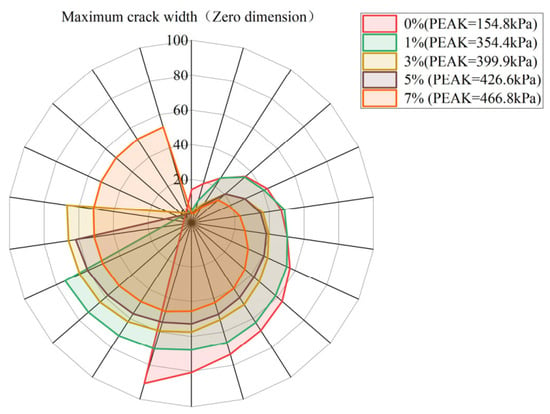
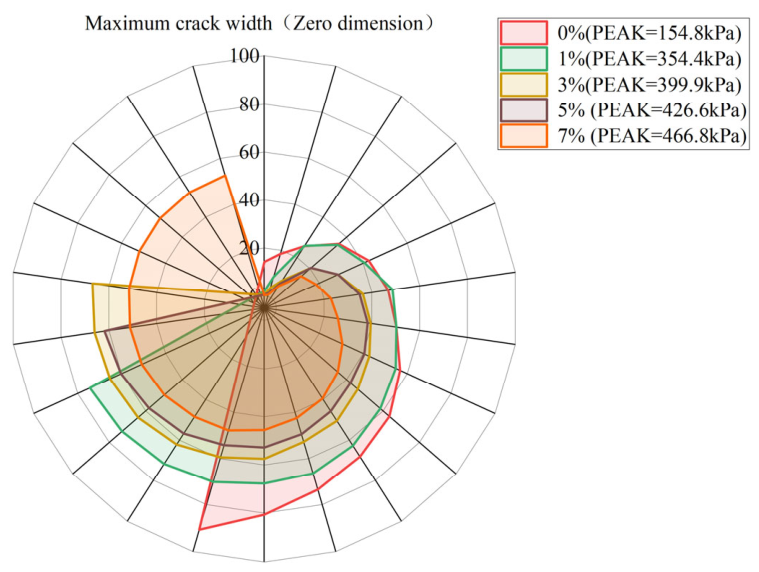
As shown in Figure 10, the maximum crack width of specimens in each group increases continuously with the increase in applied load. At the same loading stage, specimens with higher fly ash contents possess smaller maximum crack width values. At failure, the maximum crack width of plain loess (0% fly ash) reaches 90.7, while the ultimate maximum crack widths of the 1%, 3%, 5% and 7% fly ash-modified groups are 74.4, 66.9, 61.9 and 52.6, respectively. Specimens with low fly ash contents exhibit a sharp growth of maximum crack width and severe propagation of primary cracks during loading.
Figure 10.
The relationship between UCS peak value and maximum crack width of bio-cemented loess (FA = 0%~7%).
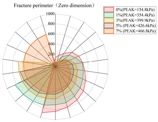
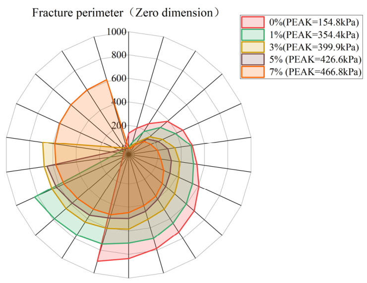
As shown in Figure 11, the total crack length (fracture perimeter) of specimens in each group rises continuously with the increase in applied load. At the same loading stress level, specimens with higher fly ash contents exhibit shorter total crack lengths. At failure, the ultimate total crack length of plain loess (0% fly ash) reaches 896.4, while the ultimate fracture perimeters of the 1%, 3%, 5% and 7% fly ash-modified groups are 829.4, 688.6, 651.5 and 615.8, respectively. Specimens with low fly ash contents undergo a dramatic increase in total crack length throughout loading, accompanied by sufficient crack propagation and penetration.
Figure 11.
The relationship between UCS peak value and fracture perimeter of bio-cemented loess (FA = 0%~7%).
The extension paths of internal cracks are effectively blocked with the increase in fly ash content. Fly ash particles fill soil pores and redistribute concentrated stress synergistically with the biogenic calcium carbonate cementation skeleton, which significantly restrains crack propagation and expansion. There exists an obvious negative correlation between unconfined compressive strength and total crack length. Fly ash modification can simultaneously improve the bearing capacity of soil and reduce the scale of crack extension. The improvement effect presents a marginal diminishing trend: the most prominent reduction in total crack length occurs when fly ash content increases from 0% to 3%, and the growth rate of crack inhibition slows down once the content exceeds 3%. The fly ash content of 7% balances high compressive strength and limited crack extension, which is confirmed as the optimal mixing proportion in this test.
This study quantitatively compares the threshold segmentation method, edge detection method and CIMBMFMR method from three dimensions including crack identification accuracy, microcrack detection capability and physical consistency based on the extracted crack parameter results of the three methods, so as to verify the effectiveness and superiority of the CIMBMFMR method (Table 6). However, the parameters obtained by the threshold segmentation method and edge detection method deviate from objective reality and fail to reflect actual crack characteristics, which highlights an urgent demand for novel crack identification approaches.
Table 6.
Comparison of crack identification performance among threshold segmentation, edge detection and CIMBMFMR method.
Both the threshold segmentation method and edge detection method have defects when identifying cracks in loess modified by plant-derived urease (BC) and fly ash. The former fails to accurately segment cracks and background with similar gray values, while the latter shows weak response to microcracks and is susceptible to texture interference. The crack parameters extracted by the two traditional methods are physically inconsistent, and their crack reduction rates (88%–98%) are severely mismatched with the growth rate of soil strength. In contrast, the CIMBMFMR method integrates mechanical characteristic parameters derived from stress–strain responses, and it significantly outperforms conventional approaches in terms of identification accuracy (94.6%), microcrack detection rate (79.2%) and physical consistency (|R| = 0.94). This method realizes a paradigm shift from “appearance-based crack recognition” to “damage early warning based on intrinsic mechanism”.
6. Discussion
- (1)
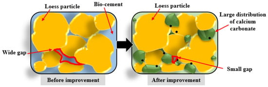
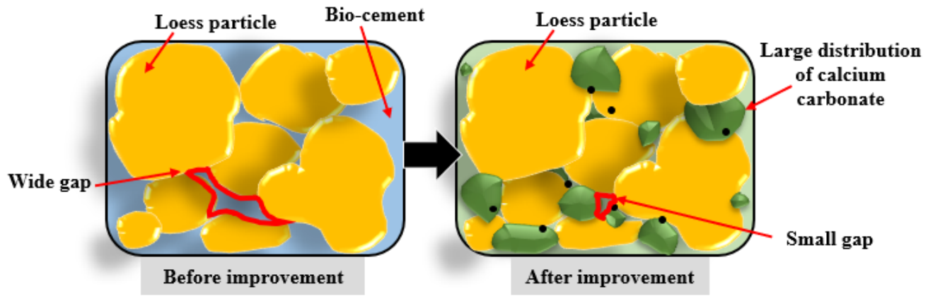
- Accelerated freeze–thaw tests ranging from 0 to 15 cycles reveal that the deterioration in strength and permeability of modified soil mainly occurs within the first 5 cycles, with a maximum peak strength reduction of 33.29%, and the soil structure gradually stabilizes after 10 cycles. Untreated loess lacks calcium carbonate cementation, resulting in a strength of only 154.8 kPa and severe structural damage after freeze–thaw exposure. The BC-FA system generates various calcium carbonate crystals to fill pores and form bridging cementation between soil particles (Figure 12). A fly ash dosage of 7% greatly boosts calcium carbonate production, cuts the permeability coefficient by 61.58% compared with plain loess, blocks water migration channels, and markedly improves the structural integrity of soil under long-term freeze–thaw conditions. Although the current study has not covered independent tests on aging, wet–dry cycles and chemical erosion, the material exhibits outstanding long-term engineering durability potential owing to the continuous stable cementation network formed by calcium carbonate minerals and the excellent water stability of calcium carbonate binders. Follow-up accelerated aging tests including long-duration wet–dry cycles and immersion in multi-concentration chemical solutions will be carried out to quantitatively characterize the degradation evolution of performance under long-term service conditions.Figure 12. Improvement mechanism diagram.
- (2)
- Existing research has confirmed that MICP tends to cause pore sieving blockage when stabilizing fine-grained soils. Microbial metabolism ceases under low temperatures, resulting in significant strength attenuation after freeze–thaw cycles; furthermore, this technology is plagued by drawbacks including high curing costs and ammonium salt contamination [29,30]. Although plant-based bio-cement avoids the permeability limitation induced by bacterial cells, it lacks nucleation carriers, leading to scattered distribution of calcium carbonate crystals and obvious deficiencies in strength increment and frost resistance [31,32,33]. The BC-FA composite system synergized with fly ash takes full advantage of fly ash particles to supply abundant nucleation sites and facilitate uniform precipitation of calcium carbonate. Three types of crystals (calcite, aragonite and vaterite) are formed to construct a continuous cementation network, which greatly alleviates structural deterioration triggered by frost heave [34,35]. From an engineering application perspective, BC-FA realizes the resource recycling of fly ash solid waste and boasts outstanding low-carbon and eco-friendly advantages. Its only shortcoming lies in the fact that the optimal fly ash dosage has merely been verified by laboratory tests without field-scale validation. Compared with MICP, the BC-FA system is more applicable to green reinforcement projects in loess areas subjected to freeze–thaw cycles.
7. Conclusions
This study addresses the performance deterioration of loess under extreme freeze–thaw environments by employing a novel improvement method combining plant-based bio-cement (BC) with fly ash (FA) through systematic laboratory investigations on Weinan loess. Integrating biomineralization with geotechnical engineering principles, this technology represents a green, low-carbon, and eco-friendly improvement material. Through mechanical tests, permeability measurements, and SEM/XRD microscopic analyses, the evolution of mechanical properties, seepage characteristics, and microstructure of loess before and after improvement under freeze–thaw cycles was systematically investigated. The intrinsic correlation between freeze–thaw damage and performance degradation was quantitatively revealed, and the solidification mechanism of BC-FA synergistic improvement was elucidated. The findings provide theoretical support and a scientific basis for loess improvement engineering in extreme climate regions. The main conclusions are as follows:
- (1)
- The BC-FA treatment markedly enhances the strength and impermeability of Weinan loess. The unconfined compressive strength of specimens amended with 7% FA reached 466.8 kPa, which is 201.6% higher than that of untreated loess (154.8 kPa). Simultaneously, the permeability coefficient decreased by 61.58%, demonstrating that the combined modification effectively seals water migration pathways and improves the soil’s resistance to external hydraulic actions. The degradation of both strength and permeability primarily occurs within the initial five freeze–thaw cycles, with a peak strength reduction of 33.29%. Beyond ten cycles, the attenuation rate diminishes significantly and the soil structure approaches a relatively stable state. This stabilization indicates that the BC-FA cementation network can sustain its reinforcing effect under repeated freeze–thaw actions, providing reliable long-term durability.
- (2)
- Biomineralization induced by plant-based urease generates three crystalline forms of calcium carbonate (calcite, aragonite, and vaterite), as confirmed by XRD analysis. These crystals adhere to particle surfaces, fill inter-granular voids, and establish bridging contacts between adjacent soil particles. This dual action of pore filling and particle cementation constructs a continuous and stable skeleton, which fundamentally enhances the structural integrity and mechanical resilience of the improved loess. The proposed CIMBMFMR method, which integrates mechanical response parameters with multi-feature image processing, overcomes the limitations of conventional threshold segmentation and edge detection techniques. By establishing a quantitative mapping between mechanical deterioration, micro-damage accumulation, and crack propagation, this approach achieves high identification accuracy (94.6%) and microcrack detection rate (79.2%), while maintaining strong physical consistency (|R| = 0.94).
- (3)
- The BC-FA system not only achieves resource recycling of fly ash solid waste but also exhibits significant low-carbon and eco-friendly characteristics, aligning with the goals of sustainable development. Overall, this green bio-cementation technology provides a feasible and promising solution for soil reinforcement in extreme environmental regions, with potential applications in slope stabilization, foundation treatment, and ecological restoration.
Author Contributions
J.K.: Investigation, Data organization; B.Z.: Visualization, Formal analysis, Writing—original draft; X.L.: Conceptualization, Methodology; J.D.: Draft, Conceptualization; H.Y.: Methodology; W.Y.: Funding acquisition. All authors have read and agreed to the published version of the manuscript.
Funding
This work was funded by Shaanxi Geology and Mining Group Co., Ltd. Special Funds for Scientific Research Key Projects “Biological Reinforcement Collaborative Fiber Improved Loess Engineering Characteristics Research” (No.: KY202309). This work was supported by National Natural Science Foundation of China (Grant Nos. 42372323 and 41672305).
Institutional Review Board Statement
Not applicable.
Informed Consent Statement
Not applicable.
Data Availability Statement
Data are contained within this article.
Conflicts of Interest
Authors Jiang Kang, Bin Zhang, Xiao-Jun Liu, Jun-Ning Dai and Hao Yan were employed by the company Shaanxi Institute of Engineering Investigation Co., Ltd., and Shaanxi Geology and Mineral Resources Innovation Research Institute Co., Ltd. The remaining authors declare that the research was conducted in the absence of any commercial or financial relationships that could be construed as potential conflicts of interest.
References
- Li, Y.; Shi, W.; Aydin, A.; Beroya-Eitner, M.A.; Gao, G. Loess genesis and worldwide distribution. Earth-Sci. Rev. 2020, 201, 102947. [Google Scholar] [CrossRef] [Scilit]
- Karimi, A.; Khademi, H.; Kehl, M.; Jalalian, A. Distribution, lithology and provenance of perideset loess deposits in northeastern Iran. Geoderma 2009, 148, 241–250. [Google Scholar] [CrossRef] [Scilit]
- Li, G.; Wang, F.; Ma, W.; Fortier, R.; Mu, Y.; Mao, Y.; Hou, X. Variations in strength and deformation of compacted loess exposed to wetting-drying and freeze-thaw cycles. Cold Reg. Sci. Technol. 2018, 151, 159–167. [Google Scholar] [CrossRef] [Scilit]
- Zhang, L.; Hu, Z.; Li, H.; She, H.; Wang, X.; Yang, X.; Han, X. Water Sensitivity and Structural Properties of Loess. Adv. Civ. Eng. 2024, 2024, 1951668. [Google Scholar] [CrossRef] [Scilit]
- Hong, Q.; Lai, H.; Liu, Y. Failure analysis and treatments of collapse accidents in loess tunnels. Eng. Fail. Anal. 2023, 145, 107037. [Google Scholar] [CrossRef] [Scilit]
- Lutenegger, A.J.; Hallberg, G.R. Stability of loess. Eng. Geol. 1988, 2, 247–261. [Google Scholar] [CrossRef] [Scilit]
- Xue, C.; Wang, X.; Lian, B.; Luo, L.; Liu, K. Research on the mechanism of composite improvement of loess based on quantitative analysis of microstructure and mechanical strength. Constr. Build. Mater. 2023, 379, 131215. [Google Scholar] [CrossRef] [Scilit]
- Zhao, Y.; Zhuang, J.; Wang, Y.; Jia, Y.; Niu, P.; Jia, K. Improvement of loess characteristics using sodium alginate. Bull. Eng. Geol. Environ. 2020, 79, 1879–1891. [Google Scholar]
- Min, Z.H.U.; Wankui, N.I.; Kangze, Y.U.A.N.; Lan, L.I.; Xiangning, L.I.; Haman, W.A.N.G. Improvement and optimization of permeability and strength properties of loess. Coal Geol. Explor. 2020, 48, 27. [Google Scholar] [CrossRef] [Scilit]
- Zhang, W.; Lu, Y.; Lin, C. Lignin–MgO-based loess stabilization incorporating CO2 mineralization. Can. Geotech. J. 2025, 62, 1–23. [Google Scholar] [CrossRef] [Scilit]
- Song, H.; Jiang, S.; Zang, R.; Lin, J.X.; Cui, E.J. Bond behavior of CFRP-concrete with surface groove subjected to chloride wet-dry cycles: Experimental, strength model and design Method. Thin-Walled Struct. 2024, 195, 111499. [Google Scholar] [CrossRef] [Scilit]
- Ni, W.; Nie, Y.; Lü, X.; Fan, M. Mechanical behavior and microstructure evolution of Malan loess under dynamic compaction. Environ. Earth Sci. 2024, 83, 76. [Google Scholar] [CrossRef] [Scilit]
- Yuan, K.; Ni, W.; Zhao, L.; Wang, H. Silica fume stabilized loess: Mechanical properties, microstructural evolution and environmental analysis. Sustain. Mater. Technol. 2023, 36, e00604. [Google Scholar] [CrossRef] [Scilit]
- Yuan, K.Z.; Ni, W.K.; Lü, X.F.; Zhu, M. Experimental study on the performance of the modified loess by polypropylene fiber mixed with bentonite and cement. Bull. Eng. Geol. Environ. 2022, 81, 302. [Google Scholar] [CrossRef] [Scilit]
- Cheng, X.; Qi, L.; Zha, W.; Zhou, Y.; Gao, F.; Zou, W. Experimental study on cement improved loess. Int. J. Pavement Res. Technol. 2022, 15, 384–394. [Google Scholar]
- Yang, X.; Hu, Z.; Li, L.; Wang, X.; Zhou, X. Strength properties, microstructural evolution, and reinforcement mechanism for cement-stabilized loess with silica micro powder. Case Stud. Constr. Mater. 2024, 20, e02848. [Google Scholar] [CrossRef] [Scilit]
- Venkata Sudhakar, C.; Reddy, U. Impacts of cement industry air pollutants on the environment and satellite data applications for air quality monitoring and management. Environ. Monit Assess 2023, 195, 840. [Google Scholar] [CrossRef] [Scilit]
- Elehinafe, F.B.; Ezekiel, S.N.; Okedere, O.B.; Odunlami, O.O. Cement industry–Associated emissions, environmental issues and measures for the control of the emissions. Mech. Eng. Soc. Ind. 2022, 2, 17–25. [Google Scholar] [CrossRef] [Scilit]
- Ibrahim, O.A.; Abbas, A.; Hassanin, A.I.; Ibrahim, W.; Abd-Elnaby, S.F.M. A Literature Review of Bio-cement: Microorganisms, Production, Properties, and Potential Applications. ERU Res. J. 2023, 2, 554–574. [Google Scholar] [CrossRef] [Scilit]
- Fu, X.; Ye, W.J.; Yuan, G.; Zhang, X.L.; Niu, R.Y. Experimental Study on Mechanical Properties of Cured Sand Combined with Plant-Based Bio-cement (PBBC) and Organic Materials. Appl. Biochem. Biotechnol. 2024, 197, 1865–1888. [Google Scholar] [CrossRef] [Scilit] [PubMed]
- Ye, W.J.; Fu, X.; Wu, Y.T.; Zhou, Z.H.; Ma, Q.Q. Experimental study on the mechanical properties of desert sand improved by the combination of additives and bio-cement. Bioprocess Biosyst. Eng. 2024, 47, 1453–1469. [Google Scholar] [CrossRef] [Scilit] [PubMed]
- Kidanemariam, T.G.; Gebru, K.A.; Kidane Gebretinsae, H. A mini review of enzyme-induced calcite precipitation (EICP) technique for eco-friendly bio-cement production. Environ. Sci. Pollut. Res. 2024, 31, 16206–16215. [Google Scholar] [CrossRef] [Scilit]
- Qi, J.; Zhang, J.; Zhu, Y. The geotechnical significance of the effect of freeze-thaw action on soil structure. Chin. J. Rock Mech. Eng. 2003, 22, 2690–2694. (In Chinese) [Google Scholar]
- Yao, X.; Huang, G.; Wang, M.; Dong, X. Mechanical properties and microstructure of PVA fiber reinforced cemented soil. KSCE J. Civ. Eng. 2021, 25, 482–491. [Google Scholar] [CrossRef] [Scilit]
- Lee, J.; Kim, Y.S.; Chae, D.; Cho, W. Loading rate effects on strength and stiffness of frozen sands. KSCE J. Civ. Eng. 2016, 20, 208–215. [Google Scholar] [CrossRef] [Scilit]
- Mehmood, M.; Guo, Y.; Wang, L.; Liu, Y.; Uge, B.U. Influence of enzyme induced carbonate precipitation (EICP) on the engineering characteristics of expansive soil. Arab. J. Sci. Eng. 2024, 49, 14101–14116. [Google Scholar] [CrossRef] [Scilit]
- Cheng, L.; Cord-Ruwisch, R.; Shahin, M.A. Cementation of sand soil by microbially induced calcite precipitation at various degrees of saturation. Can. Geotech. J. 2013, 50, 81–90. [Google Scholar] [CrossRef] [Scilit]
- van Paassen, L.A.; Ghose, R.; van der Linden, T.J.; van der Star, W.R.; van Loosdrecht, M.C. Quantifying biomediated ground improvement by ureolysis: Large-scale biogrout experiment. J. Geotech. Geoenviron. Eng. 2010, 136, 1721–1728. [Google Scholar] [CrossRef] [Scilit]
- Zhang, H.N.; Jia, C.Q.; Wang, G.H.; Su, F.; Sun, Y.S.; Fan, C.Y. Physical-mechanical properties of microbially induced calcite precipitation-treated loess and treatment mechanism. J. Mt. Sci. 2022, 19, 2952–2967. [Google Scholar] [CrossRef] [Scilit]
- Hoang, T.; Alleman, J.; Cetin, B.; Choi, S.G. Engineering properties of biocementation coarse-and fine-grained sand catalyzed by bacterial cells and bacterial enzyme. J. Mater. Civ. Eng. 2020, 32, 04020030. [Google Scholar] [CrossRef] [Scilit]
- Li, Y.; Zhou, S.; Liu, F.; Dong, Z.; Fan, X.; Ge, Z.; Li, C.; Zhang, H. Enzyme-Induced Carbonate Precipitation (EICP) for Soil Stabilization: A Review of Mechanisms, Applications, and Future Challenges. Geotechnics 2026, 6, 53. [Google Scholar] [CrossRef] [Scilit]
- Cui, M.J.; Chu, J.; Lai, H.J. Optimization of one-phase-low-pH enzyme-induced carbonate precipitation method for soil improvement. Acta Geotech. 2024, 19, 1611–1625. [Google Scholar] [CrossRef] [Scilit]
- Xu, W.; Zheng, J.; Lai, H.; Cui, M. Sustainable heavy metal immobilization in contaminated soils using plant-derived urease-driven biomineralization. PLoS ONE 2025, 20, e0331241. [Google Scholar] [CrossRef] [Scilit] [PubMed]
- Dang, T.; Ji, Y.; Guo, Y.; Ma, F.; Zhang, Z.; Liang, B.; Rong, X. Experimental research on the feasibility of phosphogypsum-enzyme induced carbonate precipitation (EICP) solidified loess. Sci. Rep. 2025, 15, 29683. [Google Scholar] [CrossRef] [Scilit] [PubMed]
- Gao, J.; Wang, J.; Zhang, D.; Wang, F.; Qi, L. Enzyme-induced calcium carbonate precipitation treated loess fly ash-based geopolymer for airport slope stabilization: Evaluation of wetting deformation and Vibratory disintegration. Case Stud. Constr. Mater. 2025, 22, e04345. [Google Scholar] [CrossRef] [Scilit]

Disclaimer/Publisher’s Note: The statements, opinions and data contained in all publications are solely those of the individual author(s) and contributor(s) and not of MDPI and/or the editor(s). MDPI and/or the editor(s) disclaim responsibility for any injury to people or property resulting from any ideas, methods, instructions or products referred to in the content. |
© 2026 by the authors. Licensee MDPI, Basel, Switzerland. This article is an open access article distributed under the terms and conditions of the Creative Commons Attribution (CC BY) license.