Article

Effect of CFRP Geometry on the Repair Performance of Corroded Steel Pipelines: A Finite Element Study

Department of Mechanical Engineering, College of Engineering, King Faisal University, Al-Ahsa 31982, Saudi Arabia
Coatings 2026, 16(7), 814; https://doi.org/10.3390/coatings16070814
Submission received: 6 June 2026 / Revised: 27 June 2026 / Accepted: 6 July 2026 / Published: 9 July 2026
(This article belongs to the Section Architectural and Infrastructure Coatings)

Highlights

What are the main findings?
CFRP thickness strongly controlled hoop stress reduction.
Repair length beyond full defect coverage had limited benefit.
Deeper corrosion defects required proportionally thicker CFRP repair.
What are the implications of the main findings?
CFRP repair design should prioritize thickness over excessive length.
The t c / a ratio can guide preliminary CFRP thickness selection.
Efficient CFRP sizing may reduce unnecessary repair material usage.

Abstract

Carbon fiber-reinforced polymer (CFRP) repair is widely used to rehabilitate corroded steel pipelines; however, the relative influence of CFRP repair geometry on stress reduction remains insufficiently quantified. This study investigated the effects of CFRP thickness and repair length on the hoop stress response of steel pipelines containing circumferentially uniform longitudinal corrosion defects under internal pressure. An axisymmetric finite element model was developed in ABAQUS and verified against an analytical multilayer cylinder solution based on the Lamé thick-cylinder theory. The model was based on an idealized circumferentially uniform corrosion defect, linear elastic material behavior, and perfect bonding between the steel pipe, epoxy filler, and CFRP repair layer. A parametric study was performed by varying the defect depth, defect length, CFRP thickness, and repair length. The results showed that CFRP thickness was the dominant parameter controlling the repair effectiveness. For the deepest defect case, increasing the CFRP thickness ratio from 0.25 to 0.75 increased the hoop stress reduction from approximately 40% to more than 58% for the shorter defect and from approximately 40% to more than 62% for the longer defect case. In contrast, increasing the repair length beyond full defect coverage produced only marginal additional stress reduction. Based on a 10% stress-tolerance criterion relative to the intact pipe response, the required CFRP thickness-to-defect-depth ratio increased with defect severity. These findings support the preliminary CFRP repair sizing by prioritizing repair thickness over excessive repair length.

1. Introduction

Steel pipelines are widely used for transporting oil, gas, and water because of their high structural efficiency, reliability, and cost effectiveness. However, long-term exposure to harsh operating and environmental conditions can lead to corrosion damage, which remains a major threat to pipeline integrity [1,2]. Corrosion reduces the effective wall thickness of a pipe, increases the local hoop stress, and may compromise safe operation if the damaged region is not repaired [3,4,5]. Therefore, efficient repair methods are required to restore the stress response of corroded pipelines while minimizing service interruptions and repair costs [1,6,7].
Carbon fiber-reinforced polymer (CFRP) repair systems have gained increasing attention as alternatives to conventional metallic repair methods [8,9,10]. CFRP materials offer a high strength-to-weight ratio, corrosion resistance, ease of installation, and adaptability to curved pipe surfaces [11,12]. When externally bonded to a damaged pipe, the CFRP layer provides additional stiffness and helps transfer part of the pressure-induced hoop stress away from the corroded steel region [6,7,13]. The effectiveness of this repair mechanism depends not only on the material properties of the CFRP system but also on the selected repair geometry [14,15,16].
Previous finite element studies have shown that CFRP repairs can reduce stress concentration, delay yielding, and improve the structural response of corroded or damaged pipelines under internal pressure [6,7,10,17,18]. However, many of these studies focused on selected repair configurations, burst or failure behaviors, or comparisons between repaired and unrepaired pipes, rather than systematically separating the individual roles of CFRP thickness and repair length. This distinction is important because the two geometric parameters contribute to the repair performance through different mechanisms. The CFRP thickness directly increases the circumferential stiffness of the repair layer and improves the load sharing between the damaged steel wall and the composite, whereas the repair length mainly controls the bonded coverage beyond the defect region [6,10,19,20]. Therefore, the present study differs from previous numerical investigations in that it explicitly isolates these two geometric effects and quantifies their relative influence on the elastic hoop stress recovery of repaired pipes.
Another limitation of the existing literature is that stress-reduction results are not always translated into a simple normalized thickness requirement. Existing design-oriented approaches, such as ASME PCC-2 [21] ess using allowabl [22] sress or allowable strain criteria for a specified repair condition [23]. These approaches are essential for repair qualification, but they do not directly show how the required CFRP thickness varies with defect depth, defect length, and repair geometry when the objective is to recover the elastic hoop-stress response to that of an intact pipe. In the present study, the required repair thickness is expressed using the normalized ratio t c / a , where t c  is the CFRP thickness and a  is the defect depth. This ratio provides a direct measure of the CFRP thickness required relative to the severity of wall loss and allows different defect depths to be compared within a single stress-based framework. Therefore, the proposed t c / a  guideline is not intended to replace code-based design procedures, but to provide a preliminary elastic stress-control map that links defect severity to the CFRP thickness needed to satisfy a prescribed stress-tolerance criterion.
In this study, a circumferentially uniform longitudinal corrosion defect was considered as an idealized conservative case in which the wall loss extended continuously around the pipe circumference. This assumption enables the use of an axisymmetric finite element framework while preserving the primary stress-transfer mechanism between the steel pipe, epoxy filler, and CFRP repair layer. It also allows an efficient parametric investigation of CFRP repair geometry under internal pressure without the computational cost associated with three-dimensional localized corrosion models. Accordingly, this study aimed to evaluate the effect of CFRP repair geometry on the hoop stress response of corroded steel pipelines. An axisymmetric finite element model was developed in ABAQUS/Standard (version 2025; Dassault Systèmes SIMULIA Corp., Johnston, RI, USA) and verified against an analytical multilayer cylinder solution based on the Lamé thick-cylinder theory. An additional literature-based verification was also performed by reproducing selected elastic wall-thinning cases from Saeed et al. [23]. The effects of CFRP thickness, repair length, defect depth, and defect length were systematically investigated using the maximum inner hoop stress as the primary response variable. The specific contributions of this study are: (i) separating the effects of CFRP thickness and repair length on elastic hoop-stress reduction, (ii) identifying the relative dominance of CFRP thickness once the defect is fully covered, and (iii) developing a normalized t c / a -based thickness guideline using a 10% stress-tolerance criterion relative to the intact pipe response. The results provide practical insights into the relative importance of CFRP thickness and repair length and support preliminary elastic stress-based repair sizing of corroded steel pipelines.

2. Materials and Methods

2.1. Overview of Study Design

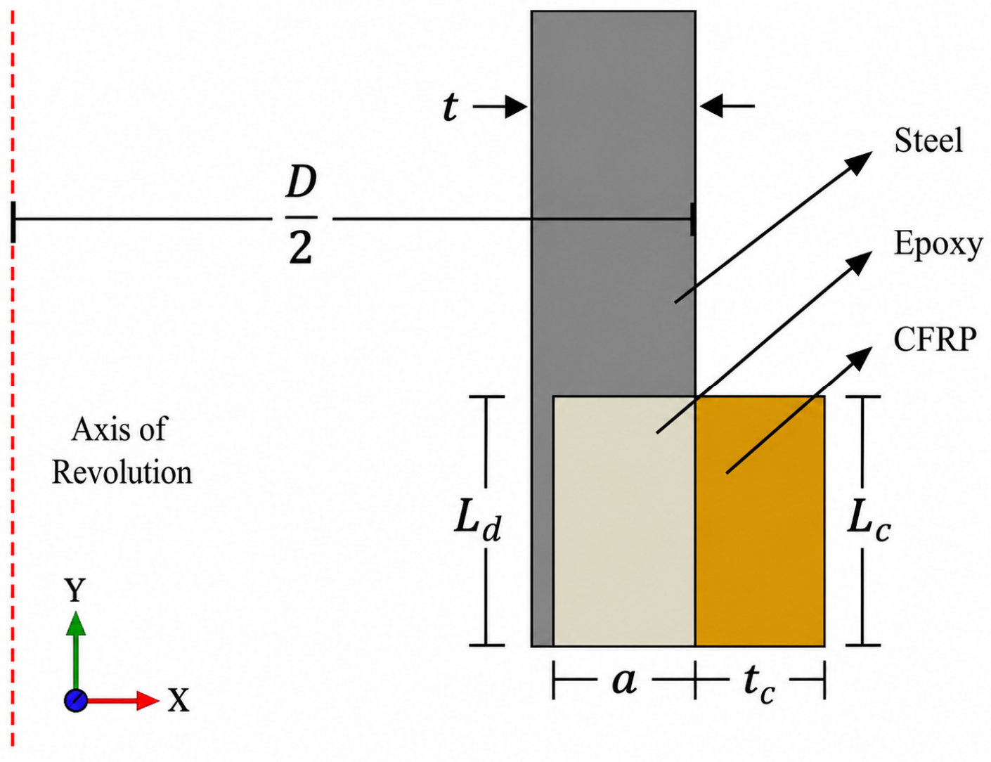
This study investigates the effectiveness of externally bonded carbon fiber-reinforced polymer (CFRP) repair systems for steel pipes containing longitudinal corrosion defects subjected to internal pressure. The investigated defect was assumed to be circumferentially uniform, representing an idealized condition in which the material loss extended continuously around the pipe circumference. Such a defect configuration enables the use of an axisymmetric finite element (FE) framework and represents a conservative case owing to extensive circumferential wall loss. The geometric configuration of the repaired pipe system, including the steel pipe, corrosion defect, epoxy filler, and CFRP repair layer, is shown in Figure 1.
The investigated steel pipe had an outer diameter of D = 406.4  mm, a wall thickness of t = 20.32  mm, and a total length of  L = 4064  mm. Due to geometric and loading symmetry, only half of the pipe length L / 2 = 2032   mm  was modeled to reduce computational cost. The corrosion defect was represented as a longitudinal rectangular metal-loss region characterized by a defect depth a  and defect length L d , while the CFRP repair was characterized by the repair thickness t c  and repair length L c , as shown in Figure 1. The corrosion defect was assumed to represent external metal loss that formed before repair owing to environmental exposure and local degradation of the outer surface of the pipe. Prior to CFRP application, the corrosion products were assumed to be removed, and the corroded region was restored to its original external profile using an epoxy filler layer with a thickness equal to the defect depth a . The CFRP repair was then symmetrically applied over the filled defect region and was assumed to be perfectly bonded to the pipe through the epoxy filler layer.
A parametric study was conducted to investigate the influence of CFRP geometry and defect dimensions on the repair effectiveness. As summarized in Table 1, the investigated parameters included defect length ratios of L d / D = 0.25  and 0.50 , repair length ratios of L c / L d = 1.00 , 1.50 , and 2.00 , CFRP thickness ratios of t c / t = 0.25 , 0.50 , and 0.75 , and defect depth ratios of a / t = 0.25 , 0.50 , and 0.75 . A total of 54 FE simulations were conducted by considering all the parameter combinations. The selected defect length ratios were chosen to evaluate the influence of defect length on CFRP repair effectiveness, while avoiding unnecessarily long defects, as previous work demonstrated that defect lengths exceeding L d / D = 0.50  have a negligible influence on the hoop stress response [24]. The pipe diameter, internal pressure, CFRP elastic properties, CFRP fiber orientation, and epoxy filler thickness were kept constant to isolate the effects of CFRP repair thickness, repair length, defect depth, and defect length on the elastic hoop-stress response.
The pipe was subjected to a uniform internal pressure of P = 10  MPa, corresponding to an operating condition that remained within the elastic range of the steel material. Therefore, all the materials were modeled as linearly elastic to evaluate the effectiveness of the CFRP repair within the elastic operating range. The maximum inner hoop stress along the pipe length was adopted as the primary response parameter to quantify the repair effectiveness. In addition, a 10% stress tolerance criterion relative to the intact pipe response was considered to determine the minimum CFRP thickness required for effective repair.

2.2. Finite Element Modeling

2.2.1. Material Properties

The mechanical properties of the steel pipe, epoxy filler, and CFRP repair material are summarized in Table 2. Since the applied internal pressure of P = 10 MPa did not induce yielding in the steel pipe, all materials were modeled as linearly elastic to evaluate the effectiveness of CFRP repair within the elastic operating range. The steel pipe and epoxy filler were modeled as isotropic linear elastic materials. The steel pipe was assigned a Young’s modulus of E = 206,000 MPa and a Poisson’s ratio of ν = 0.30 , while the epoxy filler was assigned E = 3000 MPa and ν = 0.35 . The epoxy filler was used to restore the corroded region to its original external profile prior to CFRP application.
The CFRP repair layer was modeled as an orthotropic linear elastic material using the engineering constants listed in Table 2. To represent the primary load-carrying fiber direction under internal pressure, the CFRP was oriented such that the 3-direction aligned with the circumferential direction of the axisymmetric model. Accordingly, the highest elastic modulus E 3 = 165,000 MPa was assigned in the hoop direction to maximize the confinement effect and resistance to pressure-induced hoop stresses. The remaining orthotropic elastic constants were assigned according to the material properties summarized in Table 2.

2.2.2. Boundary Conditions and Loading

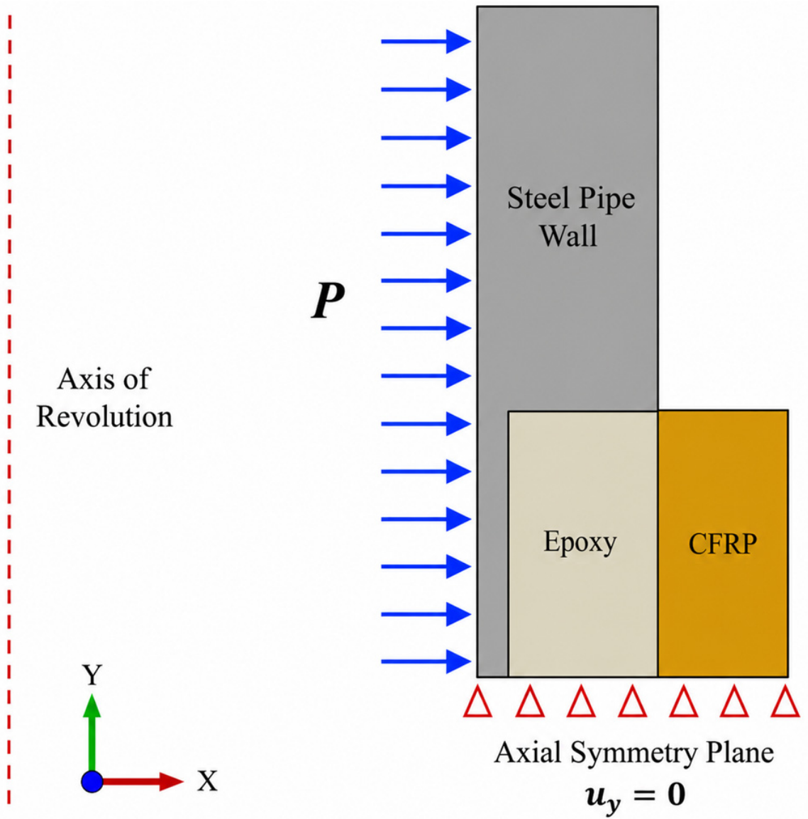
The applied boundary conditions and loading configurations are shown in Figure 2. The pipe was subjected to a uniform internal pressure of P = 10 MPa applied normal to the internal pipe surface to simulate the operating pressure condition. Due to geometric symmetry and uniform loading, only half of the pipe length L / 2 = 2032   mm was modeled to reduce computational cost. An axial symmetry condition was imposed at the symmetry plane, as shown in Figure 2, by constraining the axial displacement u y = 0 while allowing radial deformation ( u r ) . The axisymmetric condition was enforced along the axis of revolution to represent the circumferentially uniform defect geometry and loading conditions.
Perfect bonding between all the contacting surfaces was assumed to ensure full stress transfer between the steel pipe, epoxy filler, and CFRP repair layer. Therefore, tie constraints were assigned at the steel–epoxy and epoxy–CFRP interfaces to prevent relative displacement, interfacial slip, or separation during loading. In this idealized interface representation, the steel, epoxy, and CFRP layers deform compatibly at their bonded surfaces, and no cohesive-zone behavior, adhesive damage, or debonding criterion was included. This assumption represents a fully bonded repair condition and allows the influence of the CFRP geometry on the elastic hoop stress redistribution to be isolated. A static general analysis was conducted in ABAQUS with geometric nonlinearity enabled to account for the geometric effects during the pressurization.
Although geometric nonlinearity was enabled, material nonlinearity and damage evolution were not included in the present model. This modeling choice was adopted because the study focused on the elastic operating response of the repaired pipe rather than the burst pressure or progressive failure prediction. Therefore, steel plasticization, CFRP rupture or damage, epoxy filler cracking or crushing, and interfacial debonding were not considered in the model. Under pressure levels higher than those considered in this study, these mechanisms may alter the load transfer between the steel pipe, epoxy filler, and CFRP repair layer. In particular, steel yielding may redistribute the hoop stress in the corroded region, CFRP damage may reduce the stiffness contribution of the repair layer, epoxy filler damage may affect the radial support in the defect cavity, and interface degradation may reduce the composite-steel stress transfer. Accordingly, the present results should be interpreted as elastic stress-control predictions under ideal bonding conditions.

2.2.3. Stress Evaluation

The repair performance of the CFRP-repaired pipeline was evaluated based on the hoop-stress response of the steel pipe. Since internal pressure induces predominantly circumferential loading in pipelines, the hoop stress σ θ was selected as the principal response parameter for assessing repair effectiveness. The maximum inner hoop stress ( σ θ , i n n e r m a x ) was selected instead of the equivalent stress measures because the hoop stress represents the most physically relevant parameter governing the circumferential tensile loading and stress concentration in internally pressurized pipelines.
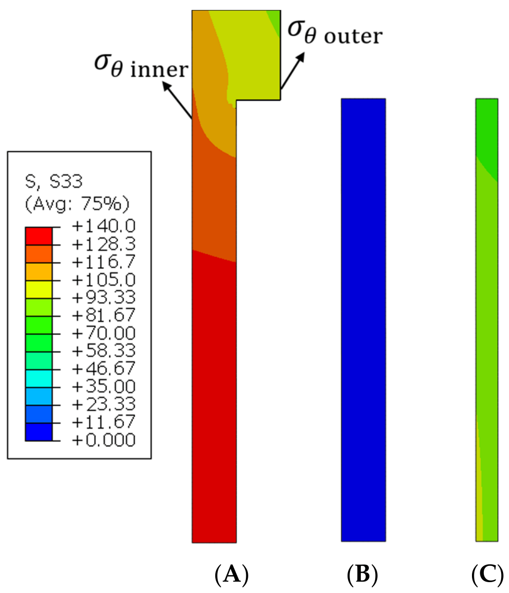
In the adopted axisymmetric finite element formulation, the circumferential stress component S 33 corresponds to the hoop stress σ θ . As illustrated in Figure 3, the hoop stress values were extracted along the inner and outer surfaces of the steel pipe, whereas the defect-end stress was evaluated at the geometric discontinuity corresponding to the end of the corrosion defect. Stress extraction was performed at the mid-length of the model to avoid end-boundary effects and ensure that the evaluated stresses reflected the local response within the defect region. The maximum inner hoop stress within the defect region was identified for each simulation and used as the primary indicator of repair effectiveness because the inner surface experiences the highest tensile stresses and, therefore, represents the most critical location for structural integrity assessment.
The hoop stresses in the epoxy filler and CFRP repair layer were also examined, as shown in Figure 3, to evaluate the stress-transfer behavior within the repaired region. The epoxy filler developed only a small hoop stress compared with the steel pipe and CFRP layer because of its lower elastic modulus. Its main role was therefore to restore the external pipe profile and provide deformation compatibility between the corroded steel surface and the external CFRP repair. In contrast, the CFRP layer developed a tensile hoop stress, confirming that part of the pressure-induced circumferential load was transferred from the damaged steel pipe to the composite repair. Since the present study focuses on elastic stress control rather than CFRP failure prediction, the subsequent parametric analysis focused on the maximum inner hoop stress of the steel pipe, which represents the critical stress-control parameter for evaluating repair effectiveness.
During the mesh convergence analysis, the hoop stresses at the inner and outer surfaces of the steel, and defect-end location were monitored to ensure numerical stability in regions with elevated stress gradients. However, for the parametric study, the maximum inner hoop stress was selected as the primary response parameter because it directly represents the severity of tensile loading in the corroded region and provides a consistent basis for comparing the repair effectiveness of different CFRP configurations.
To quantify the effectiveness of the CFRP repair, the stress reduction percentage was calculated relative to the unrepaired pipe as follows:
Stress   Reduction   ( % ) = σ θ , u n r e p a i r e d σ θ , r e p a i r e d σ θ , u n r e p a i r e d × 100
where σ θ , u n r e p a i r e d is the maximum inner hoop stress of the unrepaired corroded pipe and σ θ , r e p a i r e d is the corresponding stress after CFRP repair. A larger percentage of stress reduction indicates more effective stress redistribution and improved repair performance. The obtained maximum inner hoop stresses were also used to determine the minimum CFRP thickness required to maintain the repaired-pipe response within 10% of the intact-pipe stress.

2.3. Mesh and Convergence Analysis

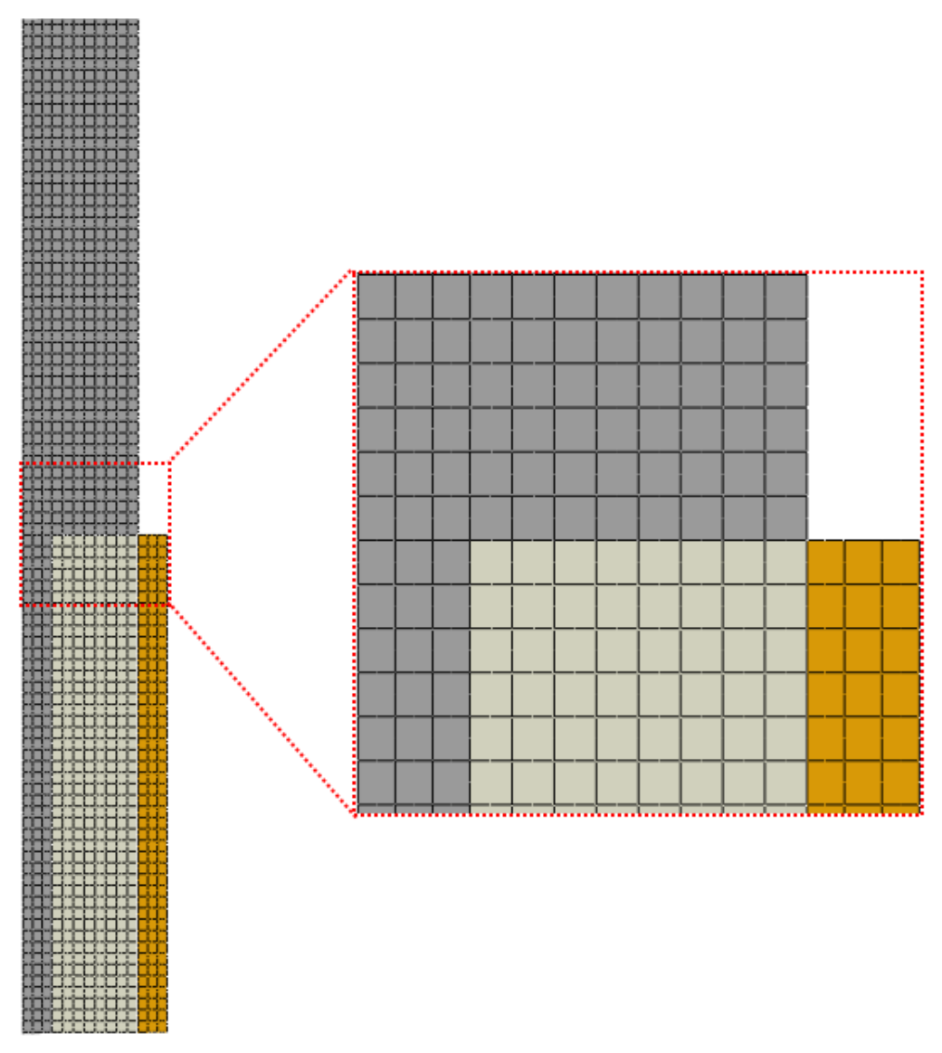
The finite element mesh adopted for the repaired pipe model is illustrated in Figure 4. A structured axisymmetric mesh was used for the steel pipe, epoxy filler, and CFRP repair layer to ensure compatible discretization across bonded interfaces. Since the present axisymmetric model required relatively low computational effort, a uniform global mesh size was adopted throughout the model rather than applying local mesh refinement.
The mesh convergence analysis was performed using a representative critical repair configuration with L d / D = 0.25 , L c / L d = 1 , t c / t = 0.25 , and a / t = 0.75 , corresponding to the deepest defect and thinnest CFRP repair considered in the parametric study. Five different global mesh sizes of 8, 4, 2, 1.5, and 1 mm were evaluated, as summarized in Table 3. The finest mesh (M5) was adopted as the reference solution for the error evaluation.
Convergence was assessed based on the maximum hoop stress at the inner surface, defect end, and outer surface of the repaired pipes. As shown in Table 3, the maximum inner hoop stress exhibited negligible sensitivity to mesh refinement, with an error of approximately 0.00% for the 2 mm mesh size relative to the reference solution. Although the defect-end and outer-surface hoop stresses were more sensitive to mesh refinement due to local stress variations near the defect and repair region, their corresponding errors for the 2 mm mesh remained below 1%, with values of 0.42% and 0.71%, respectively. Based on these results, a global mesh size of 2 mm was adopted for all subsequent simulations because it provided a suitable balance between computational efficiency and numerical accuracy.

2.4. Model Verification

The developed FE model was verified against an analytical multilayer cylinder solution based on the Lamé thick-cylinder theory [27]. The verification model was idealized as a three-layer concentric cylinder consisting of a steel pipe, epoxy layer, and CFRP layer, assuming isotropic linear-elastic behavior, perfect interfacial bonding, and open-ended loading conditions (plane stress). Under internal pressure, the radial and hoop stresses in each layer are determined using Lamé’s equations as follows:
σ r = A B r 2
σ θ = A + B r 2
where r is the radial coordinate, while A and B are Lamé constants determined by satisfying the pressure boundary conditions and radial displacement compatibility at the interfaces between adjacent layers. Since the pipe was modeled as open-ended, the radial displacement for each layer under plane stress conditions was expressed as
u ( r ) = ( 1 ν ) A r + ( 1 + ν ) B / r E
where E and ν are the Young’s modulus and Poisson’s ratio of the corresponding material layer. Perfect bonding between adjacent layers was enforced through radial displacement compatibility at the steel–epoxy and epoxy–CFRP interfaces as follows:
u 1 ( r 2 ) = u 2 ( r 2 )
u 2 ( r 3 ) = u 3 ( r 3 )
where r 2  and r 3  denote the steel–epoxy and epoxy–CFRP interface radii, respectively. The unknown interface pressures are determined by satisfying these compatibility conditions.
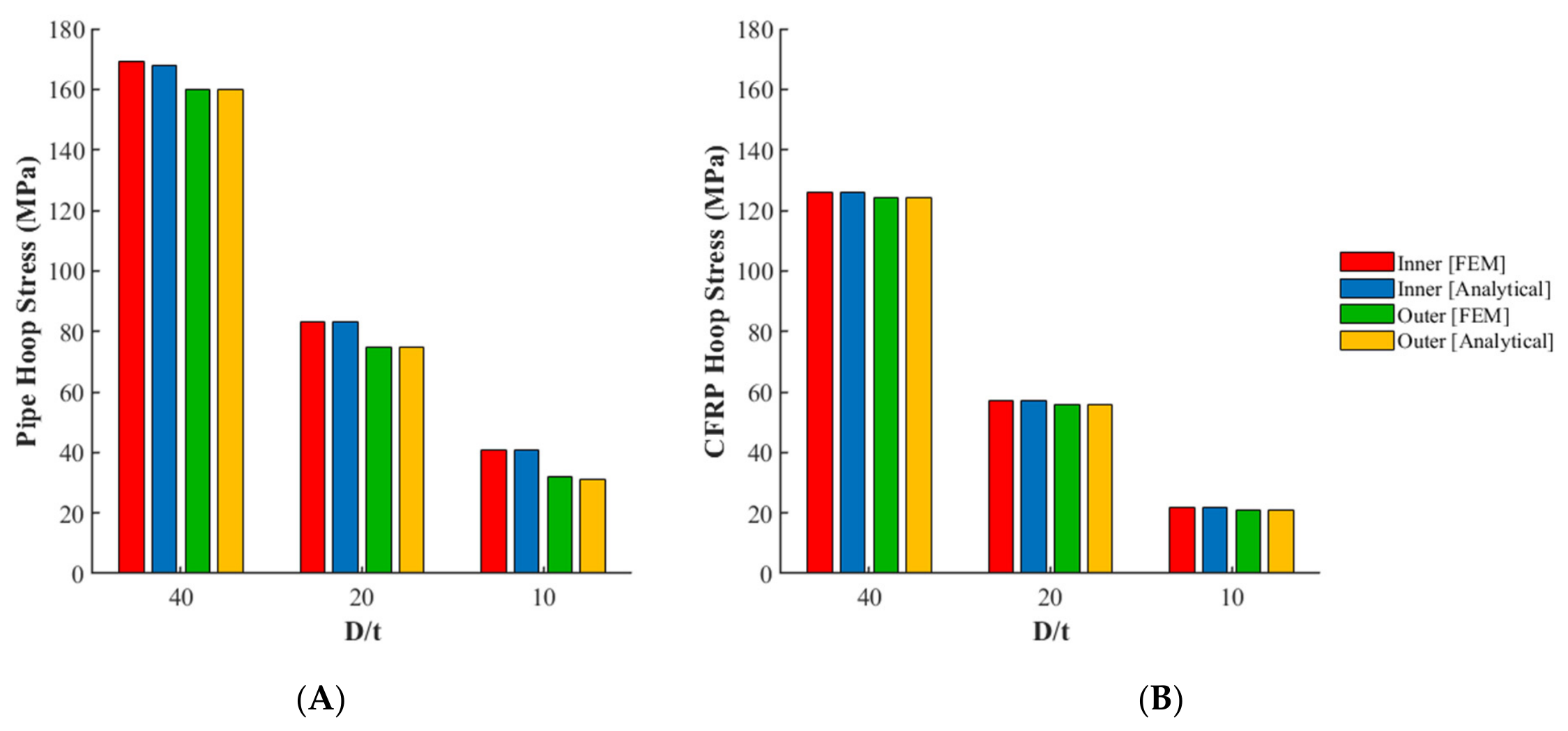
The verification was performed using repaired pipe configurations with diameter-to-thickness ratios of D / t = 40 , 20 , and 10 , corresponding to pipe wall thicknesses of t = 10.16 , 20.32 , and 40.64  mm, respectively, while maintaining a constant pipe diameter of D = 406.4  mm. The verification was performed using t e / t = t c / t = 0.20  for all investigated D / t  ratios, allowing the analytical and FE results to be compared under a consistent multilayer geometry.
Figure 5 compares the FE and analytical hoop stresses at the inner and outer surfaces of the steel pipe and CFRP layer for the investigated D / t  ratios. As shown in Figure 5, excellent agreement was achieved between the FE and analytical solutions for both the steel pipe and CFRP repair layers across all investigated cases. The close agreement between the two approaches confirms the accuracy of the developed FE model in predicting the hoop stress distribution and stress transfer behavior within the multilayer pipe system.
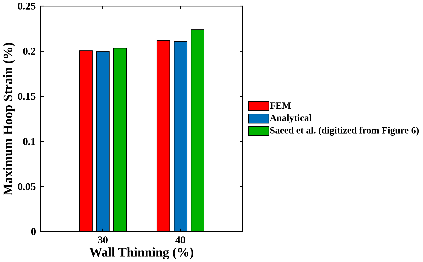
As an additional verification, the present finite element model was compared with the axisymmetric composite-repair study reported by Saeed et al. [23]. In that study, a steel pipe with circumferentially uniform wall thinning was repaired using an externally bonded composite laminate, and the hoop strain in the repair laminate was evaluated at the design pressure. Two cases were reproduced here, corresponding to 30% and 40% wall thinning, because these cases remained within or very close to the elastic response range of the steel pipe. The pipe geometry, repair thicknesses, composite material properties, and internal pressure were obtained from Saeed et al., while the strain values were digitized from their strain–deviation plot and converted using the allowable laminate strain of 0.003. The finite element results were also compared with the corresponding elastic Lamé solution for a two-layer steel-composite cylinder. As shown in Figure 6, the predicted CFRP hoop strains closely agree with the Lamé solution, with values of approximately 0.200% and 0.211% for the 30% and 40% wall-thinning cases, respectively. The comparison also shows reasonable agreement with the digitized values from Saeed et al. [23]. The small differences are attributed to digitization uncertainty and the absence of a detailed strain extraction definition in the reference study.

3. Results and Discussion

3.1. Overview of Stress Distribution in CFRP-Repaired Pipes

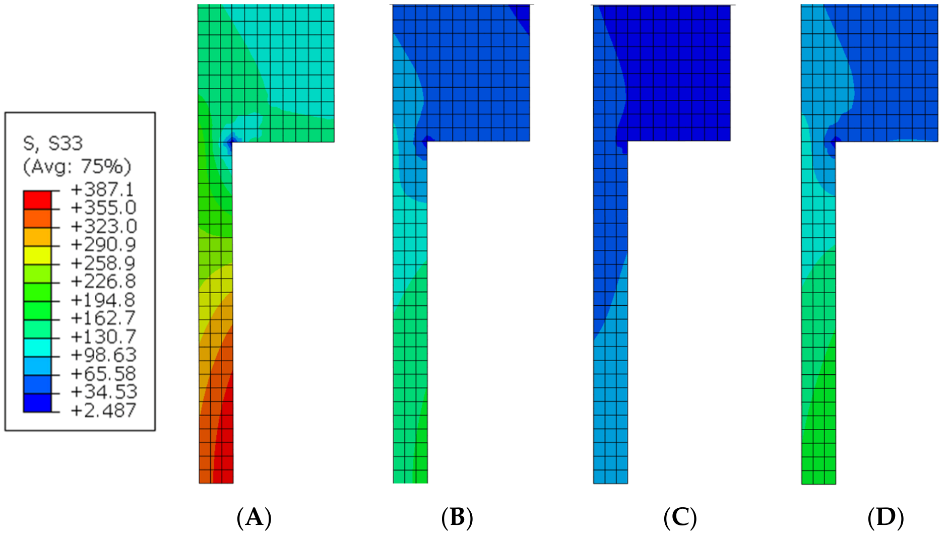
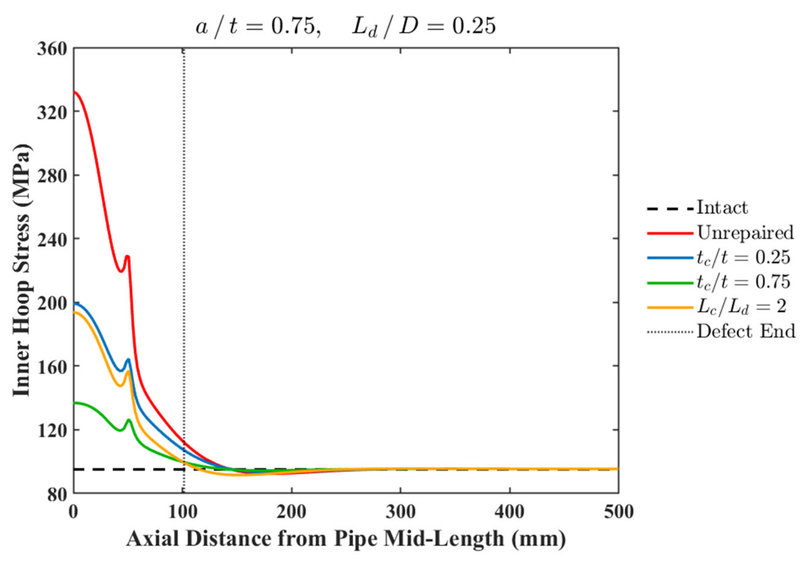
This section provides an overview of the stress distribution behavior in CFRP-repaired pipes subjected to internal pressure, with particular emphasis on the influence of CFRP thickness and repair length on the hoop stress response. Figure 7 presents representative hoop stress contours for a severe defect case with a / t = 0.75  and L d / D = 0.25 , while Figure 8 shows the corresponding inner hoop stress distributions along the pipe length. The same contour scale was used for all configurations in Figure 7, with the minimum and maximum hoop stress values shown in the shared legend, to enable direct comparison between the unrepaired and repaired cases. These representative cases were selected to illustrate the stress recovery mechanism and the role of CFRP geometry in reducing the stress concentration caused by the corrosion defects.
As illustrated in Figure 7A, the unrepaired pipe exhibited a pronounced increase in hoop stress near the defect region owing to the reduction in the effective wall thickness. The highest stress concentration occurred at the defect centerline along the inner pipe surface, where the reduced cross-sectional thickness substantially increased the local hoop stress. Far from the defect region, the hoop stress gradually recovered to the intact pipe response.
The application of CFRP repair significantly reduced the stress concentration within the damaged region, as shown in Figure 7B–D. Increasing the CFRP thickness from t c / t = 0.25  to 0.75  resulted in a substantial reduction in the local hoop stress and a more uniform stress distribution along the pipe wall, as illustrated in Figure 7B,C. In contrast, increasing the repair length from L c / L d = 1  to 2  while maintaining a constant CFRP thickness produced only a modest additional reduction in stress, as shown in Figure 7B,D.
The inner hoop stress distributions shown in Figure 8 further illustrate the stress recovery behavior along the pipe length. For the unrepaired pipe, the maximum inner hoop stress reached 332 MPa near the defect center, compared with 95.13 MPa for the intact pipe. Applying CFRP repair with t c / t = 0.25  and L c / L d = 1  reduced the peak stress to 199.23 MPa, while increasing the CFRP thickness to t c / t = 0.75  further reduced it to 136.9 MPa. In contrast, increasing the repair length from L c / L d =  1 to 2 at t c / t = 0.25  produced only a small additional reduction, from 199.23 to 193.74 MPa. These results demonstrate that CFRP thickness has a much stronger influence on stress recovery than repair length once the defect is fully covered.
Overall, the results indicate that CFRP repair effectively redistributes the hoop stress away from the defect region and promotes stress recovery toward an intact pipe response. However, the effectiveness of the repair is governed primarily by the CFRP thickness rather than the repair length, particularly when the repair fully covers the defect region.

3.2. Effect of CFRP Thickness on Repair Performance

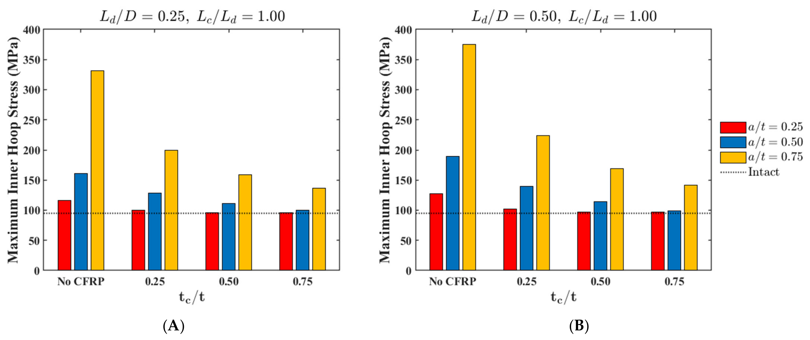
The effect of CFRP thickness on the maximum inner hoop stress is presented in Figure 9 for repaired pipes with L c / L d = 1 . Increasing t c / t  consistently reduced the maximum inner hoop stress for all investigated defect depths and defect lengths. The reduction was more pronounced for deeper defects, indicating that the CFRP thickness becomes increasingly important as the severity of wall loss increases.
For the shorter defect configuration L d / D = 0.25 , the shallow defect a / t = 0.25  showed limited sensitivity to CFRP thickness. The maximum inner hoop stress decreased from 116.42 MPa in the unrepaired pipe to approximately 96 MPa when t c / t 0.50 , which is close to the intact pipe stress of 95.13 MPa. In contrast, deeper defects exhibited a stronger dependence on CFRP thickness. For a / t = 0.50 , increasing t c / t  from 0.25 to 0.75 reduced the maximum inner hoop stress from 128.40 to 99.61 MPa, while for a / t = 0.75 , it decreased from 199.23 to 136.89 MPa.
For the longer defect configuration L d / D = 0.50 , a similar trend was observed, as shown in Figure 9B. The shallow defect again approached the intact pipe response once t c / t  reached 0.50. However, moderate and deep defects continued to benefit from the additional CFRP thickness. For a / t = 0.50 , increasing t c / t  from 0.25 to 0.75 reduced the maximum inner hoop stress from 139.54 to 99.07 MPa, while for a / t = 0.75 , it decreased from 224.15 to 141.21 MPa. These values also show that a longer defect produced higher stresses than a shorter defect, particularly for the moderate and deep defect cases.
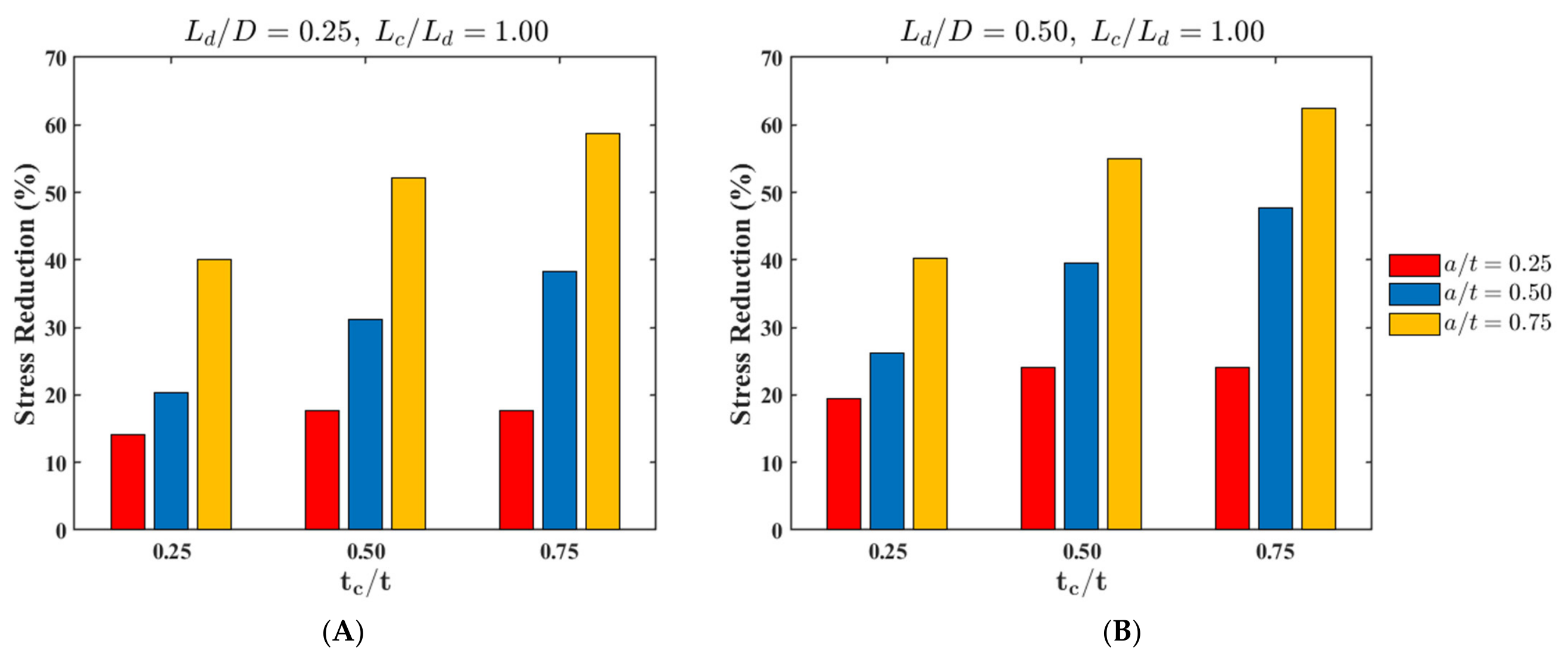
The corresponding stress reduction percentages are presented in Figure 10. For L d / D = 0.25 , increasing t c / t  from 0.25 to 0.75 increased the stress reduction from 14.19% to 17.69% for a / t = 0.25 , from 20.39% to 38.24% for a / t = 0.50 , and from 39.98% to 58.76% for a / t = 0.75 . For L d / D = 0.50 , the corresponding stress reductions increased from 19.52% to 24.02%, from 26.23% to 47.63%, and from 40.29% to 62.39%, respectively. These trends confirm that the relative benefit of increasing the CFRP thickness becomes substantially greater as the defect depth increases.
Overall, Figure 9 and Figure 10 demonstrate that CFRP thickness is a dominant repair parameter. Increasing t c / t  substantially reduced the maximum inner hoop stress, especially for moderate and deep defects. However, the improvement became limited for shallow defects once the repaired stress approached the intact pipe value, indicating diminishing returns when additional CFRP thickness was applied to less severe wall loss.
The observed influence of CFRP thickness is consistent with previous studies on the composite repair of corroded pipelines, which reported that increasing the CFRP thickness enhanced the confinement effect and promoted greater load sharing between the steel substrate and the composite repair layer [6,28]. Similar to the present findings, prior investigations generally reported that thicker CFRP repairs produced greater reductions in local hoop stress and stress concentration. The present results further quantify this behavior by showing that the benefit of increasing the CFRP thickness becomes progressively more significant as the defect severity increases, whereas diminishing returns may occur for shallow defects once the repaired stress approaches the intact pipe response.

3.3. Effect of CFRP Repair Length on Repair Performance

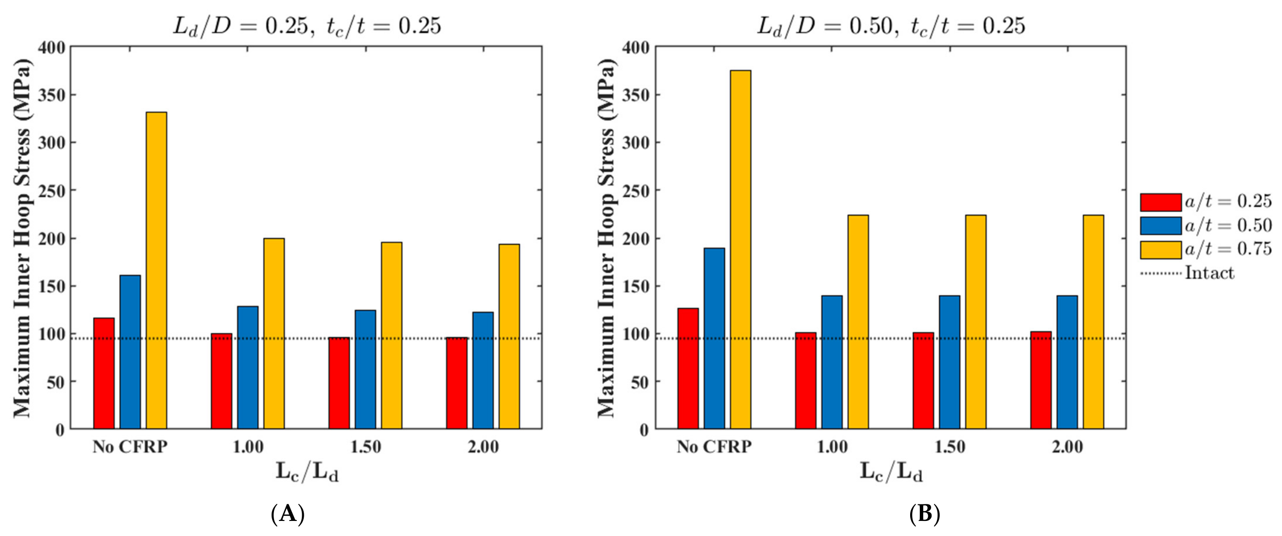
The effect of CFRP repair length on the maximum inner hoop stress is presented in Figure 11 for repaired pipes with t c / t = 0.25 . The results show that increasing L c / L d  beyond 1 produced only a limited additional reduction in the hoop stress. This indicates that once the CFRP layer fully covers the defect region, extending the repair length provides only marginal improvement.
For the shorter defect configuration L d / D = 0.25 , increasing L c / L d  from 1 to 2 reduced the maximum inner hoop stress slightly. For a / t = 0.25 , the stress decreased from 99.90 to 95.61 MPa, while for a / t = 0.50 , it decreased from 128.40 to 122.73 MPa. For the deepest defect a / t = 0.75 , the reduction was also limited, decreasing from 199.23 to 193.74 MPa. These changes were small compared with the reductions achieved by increasing the CFRP thickness, confirming that the repair length has a secondary effect on the stress response. For the longer defect configuration L d / D = 0.50 , the influence of repair length was even less pronounced, as shown in Figure 11B. Increasing L c / L d  from 1 to 2 changed the maximum inner hoop stress by less than 0.5 MPa for all defect depths, indicating that extending the repair length beyond the defect length became ineffective once the damaged region was fully covered.
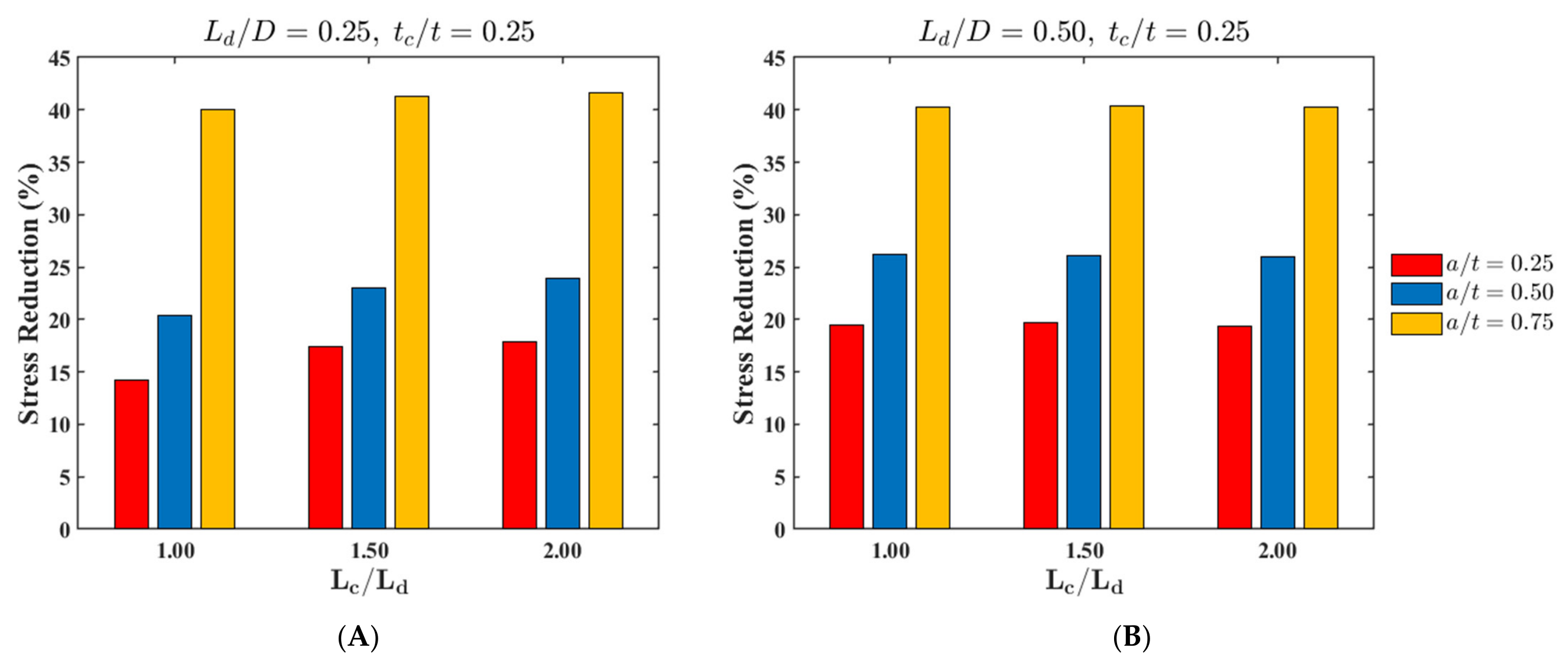
The corresponding stress reduction percentages are presented in Figure 12. For L d / D = 0.25 , increasing L c / L d  from 1 to 2 increased the stress reduction from 14.19% to 17.88% for a / t = 0.25 , from 20.39% to 23.90% for a / t = 0.50 , and from 39.98% to 41.64% for a / t = 0.75 . For L d / D = 0.50 , the stress reduction remained almost unchanged, varying by less than 1% for all defect depths. These values confirm that increasing the repair length provides little additional benefit compared with the effect of the CFRP thickness.
Overall, Figure 11 and Figure 12 demonstrate that the CFRP repair length has a relatively minor influence on the repair performance once the defect is fully covered. Extending the repair beyond L c / L d = 1  produced only marginal additional reductions in the hoop stress, particularly for the longer defect configuration. Therefore, for the investigated configurations, extending the CFRP repair beyond the defect length did not provide a meaningful stress-reduction benefit, suggesting that L c / L d = 1  is sufficient when the repair fully covers the damaged region.
The relatively limited influence of the CFRP repair length observed in this study is also generally consistent with previous studies on bonded composite repairs for corroded pipelines. Earlier investigations have suggested that extending the repair beyond the damaged region provides progressively smaller benefits once the defect is fully covered, as the primary stress concentration remains localized within the defect zone [10]. The present findings support this trend and further indicate that increasing the repair length beyond the defect length may not represent an efficient use of CFRP material when the primary objective is to reduce the maximum hoop stress [6].

3.4. CFRP Thickness Requirement for Effective Repair

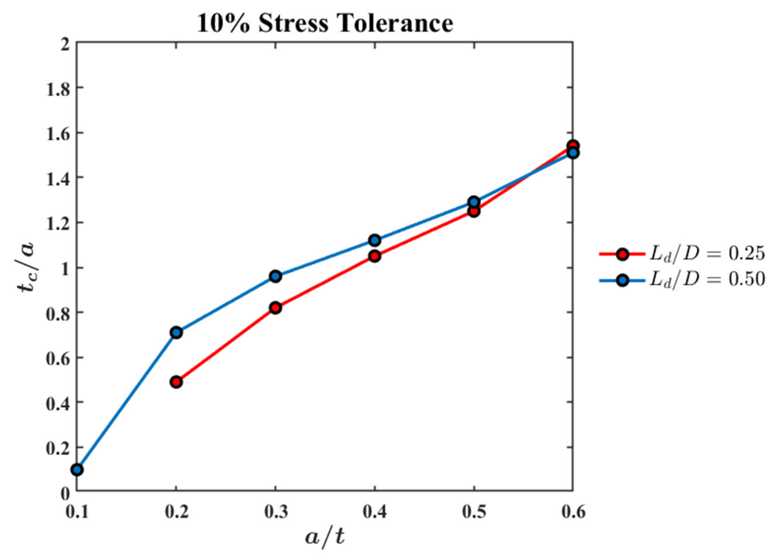
The minimum CFRP thickness required for effective repair was evaluated using a 10% stress-tolerance criterion. In this study, a repair was considered effective when the maximum inner hoop stress remained within 10% of the stress of the intact pipe. The required CFRP thickness was expressed as t c / a , where t c  is the CFRP thickness and a  is the defect depth.
Figure 13 shows the required t c / a  ratio for different defect depths and defect lengths. The required CFRP thickness increased consistently with a / t , indicating that deeper defects require proportionally thicker CFRP reinforcement. For L d / D = 0.25 , the required t c / a  increased from 0.49 at a / t = 0.20  to 1.05 at a / t = 0.40 , and further to 1.54 at a / t = 0.60 . This corresponds to an increase in the required CFRP thickness from approximately 2.0 to 18.8 mm for the same defect depth range.
For the longer defect configuration L d / D = 0.50 , the same general trend was observed. The required t c / a  increased from 0.71 at a / t = 0.20  to 1.12 at a / t = 0.40 , and reached 1.51 at a / t = 0.60 . Compared with L d / D = 0.25 , the longer defect required slightly larger t c / a  values for moderate defect depths, particularly between a / t = 0.20  and 0.40. However, the difference between the two defect lengths decreased at higher defect depths.
Overall, Figure 13 indicates that the defect depth governs the required CFRP thickness more strongly than the defect length. For moderate defects a / t = 0.30 0.40 , the required t c / a  was approximately 0.8–1.1, while for severe defects a / t = 0.50 0.60 , it increased to approximately 1.3–1.5. These results suggest that the required CFRP thickness can be estimated primarily based on the defect depth once the CFRP repair fully covers the defect region.
Although previous studies have generally reported that more severe defects require thicker CFRP reinforcement, the present results provide an explicit normalized thickness guideline using the t c / a  ratio, which may support preliminary repair design decisions for different defect severities [11,29,30].
The generalizability of the present results should be interpreted in relation to the selected parametric scope. The study was designed to isolate the effects of CFRP repair thickness, repair length, defect depth, and defect length using a fixed pipe diameter, internal pressure, CFRP material system, fiber orientation, and epoxy filler configuration. Therefore, the reported trends are most directly applicable to repaired pipes with similar elastic stiffness ratios, pressure levels, and circumferentially uniform defect assumptions. Other variables, including the pipe diameter-to-thickness ratio, internal pressure level, CFRP elastic modulus, fiber orientation, epoxy filler thickness, circumferential defect shape, and non-uniform corrosion morphology, may influence the stress-transfer mechanism and the required CFRP thickness. These factors should be investigated in future parametric studies to extend the proposed stress-based repair-thickness guideline to a broader range of pipe and repair configurations.

4. Conclusions

An axisymmetric finite element model was developed to investigate the effectiveness of CFRP repair in reducing hoop stress concentrations in steel pipelines with circumferentially uniform longitudinal corrosion defects. The effects of CFRP thickness, repair length, defect depth, and defect length on the repair performance were systematically investigated. Based on the obtained results, the following conclusions were drawn:
  • CFRP repair substantially reduced the maximum inner hoop stress within the defect region, with the repair effectiveness increasing significantly as defect severity increased. For example, for the deepest defect case a / t = 0.75  with L d / D = 0.50 , the maximum inner hoop stress decreased from 375.42 MPa in the unrepaired pipe to 224.15, 169.83, and 141.21 MPa for t c / t = 0.25 , 0.50, and 0.75, respectively.
  • The CFRP thickness was identified as the dominant repair parameter governing stress reduction. Increasing t c / t  consistently improved repair effectiveness for all investigated cases, with the influence becoming increasingly pronounced for deeper defects. For a / t = 0.75 , the stress reduction increased from approximately 40% to more than 58% for L d / D = 0.25  and from approximately 40% to more than 62% for L d / D = 0.50  as t c / t  increased from 0.25 to 0.75.
  • Increasing the CFRP repair length beyond the defect length produced only marginal improvements in the repair performance. Once the repair fully covered the defect region L c / L d = 1 , increasing the repair length to L c / L d = 2  resulted in negligible changes in the stress reduction. For example, for a / t = 0.75  and L d / D = 0.50 , the stress reduction remained nearly unchanged at approximately 40% as L c / L d  increased from 1 to 2, indicating that excessively long repairs may not represent an efficient use of the CFRP material.
  • The required CFRP thickness for effective repair increased substantially with defect severity. Based on the adopted 10% stress tolerance criterion, the required t c / a  ratio increased from approximately 0.5–0.8 for moderate defects a / t = 0.20 0.30  to approximately 1.0–1.1 for a / t = 0.40 , and further increased to approximately 1.3–1.5 for severe defects a / t = 0.50 0.60 . These findings indicate that the required CFRP thickness becomes increasingly larger than the defect depth as defect severity increases.
  • Defect depth had a substantially greater influence on repair requirements than defect length. Although increasing L d / D  from 0.25 to 0.50 slightly increased the required CFRP thickness for moderate defects, the required t c / a  ratios remained generally comparable, particularly for severe defects where both defect lengths converged to similar repair requirements.
The findings of this study are limited to the elastic stress behavior under internal pressure for open-ended steel pipelines containing circumferentially uniform longitudinal corrosion defects with perfectly bonded CFRP repairs. Therefore, the proposed repair-thickness trends should be interpreted as elastic stress-control guidance rather than burst-pressure or ultimate-limit-state predictions. When the pressure increases beyond the elastic operating range, steel plasticization, CFRP rupture or damage, epoxy filler cracking or crushing, and interfacial debonding may influence the stress redistribution mechanism and load transfer between the repaired pipe components. Nevertheless, within the adopted elastic framework, the obtained trends provide practical insights into the role of CFRP geometry in repair performance and may serve as a useful reference for the preliminary design of CFRP repairs for corroded steel pipelines.
Future work should extend the present elastic axisymmetric framework to a broader set of pipe and repair configurations, including different pipe diameter-to-thickness ratios, internal pressure levels, CFRP elastic moduli, fiber orientations, epoxy filler thicknesses, and three-dimensional localized corrosion defects with different circumferential shapes. Additional studies should also consider interfacial damage, adhesive debonding, CFRP failure, and nonlinear material behavior under higher pressure levels. Experimental validation using repaired pipe specimens would further strengthen the numerical findings and support the development of practical CFRP repair guidelines for corroded steel pipeline repair.

Supplementary Materials

The following supporting information can be downloaded at: https://www.mdpi.com/article/10.3390/coatings16070814/s1, Data S1: Structured dataset used to generate the figures and reported numerical results.

Funding

This work was supported by the Deanship of Scientific Research, Vice Presidency for Graduate Studies and Scientific Research, King Faisal University, Saudi Arabia, [Grant No. KFU263701].

Institutional Review Board Statement

Not applicable.

Informed Consent Statement

Not applicable.

Data Availability Statement

The data supporting the findings of this study are provided as Supplementary Materials in the form of a structured dataset used to generate the reported figures and numerical results.

Acknowledgments

During the preparation of this manuscript, the author used AI-based tools to improve the clarity and language of the text. The author reviewed and edited the output and takes full responsibility for the content of this publication.

Conflicts of Interest

The authors declare no conflicts of interest.

Abbreviations

The following abbreviations are used in this manuscript:
D Outer diameter of the steel pipe
t Pipe wall thickness
L Total pipe length
P Internal pressure
a Corrosion defect depth
L d Axial defect length
L c CFRP repair length
t c CFRP thickness
t e Epoxy filler thickness
D / t Pipe diameter-to-thickness ratio
a / t Defect depth ratio
L d / D Normalized defect length
L c / L d Normalized CFRP repair length
t c / t Normalized CFRP thickness ratio
t c / a CFRP thickness-to-defect depth ratio
t e / t Normalized epoxy thickness ratio
E Young’s modulus
E 1 , E 2 , E 3 Orthotropic Young’s moduli of CFRP
G 12 , G 13 , G 23 Orthotropic shear moduli of CFRP
ν Poisson’s ratio
ν 12 , ν 13 , ν 23 Orthotropic Poisson’s ratios of CFRP
r Radial coordinate
u ( r ) Radial displacement
A , B Lamé constants
q 1 , q 2 Interface pressures in the multilayer analytical solution
σ r Radial stress
σ θ Hoop stress
σ θ , m a x Maximum hoop stress
σ θ , i n n e r m a x Maximum hoop stress at the inner surface
σ θ , o u t e r m a x Maximum hoop stress at the outer surface
σ θ , d e f e c t e n d m a x Maximum hoop stress at the defect end
σ θ , i n t a c t Hoop stress of the intact pipe

References

  1. Hocine, A.; Kara Achira, F.S.; Habbar, G.; Levent, A.; Medjdoub, S.M.; Maizia, A.; Dhaou, M.H.; Bezazi, A. Structural integrity assessment of corroded pipelines repaired with composite materials—Literature review. Int. J. Press. Vessel. Pip. 2024, 210, 105253. [Google Scholar] [CrossRef]
  2. Muthanna, B.G.N.; Bouledroua, O.; Meriem-Benziane, M.; Setvati, M.R.; Djukic, M.B. Assessment of corroded API 5L X52 pipe elbow using a modified failure assessment diagram. Int. J. Press. Vessel. Pip. 2021, 190, 104291. [Google Scholar] [CrossRef]
  3. Ansari Sadrabadi, S.; Dadashi, A.; Yuan, S.; Giannella, V.; Citarella, R. Experimental-Numerical Investigation of a Steel Pipe Repaired with a Composite Sleeve. Appl. Sci. 2022, 12, 7536. [Google Scholar] [CrossRef]
  4. Kim, S.-H.; So, Y.-S.; Kim, J.-G. Fracture Behavior of Locally Corroded Steel Pipeline in District Heating System Using the Combination of Electrochemistry and Fracture Mechanics. Met. Mater. Int. 2020, 26, 1671–1678. [Google Scholar] [CrossRef]
  5. Singh, J.; Singh, S.; Pal Singh, J. Investigation on wall thickness reduction of hydropower pipeline underwent to erosion-corrosion process. Eng. Fail. Anal. 2021, 127, 105504. [Google Scholar] [CrossRef]
  6. Chen, J.; Wang, H.; Salemi, M.; Balaguru, P.N. Finite Element Analysis of Composite Repair for Damaged Steel Pipeline. Coatings 2021, 11, 301. [Google Scholar] [CrossRef]
  7. Heggab, A.; El Aghoury, I.M.; El Nemr, A. Numerical analysis for failure estimation of compositely rehabilitated corroded pipes under operational and ultimate states. Eng. Fail. Anal. 2024, 163, 108533. [Google Scholar] [CrossRef]
  8. Alabtah, F.G.; Mahdi, E.; Eliyan, F.F. The use of fiber reinforced polymeric composites in pipelines: A review. Compos. Struct. 2021, 276, 114595. [Google Scholar] [CrossRef]
  9. Alexander, C.; Ochoa, O.O. Extending onshore pipeline repair to offshore steel risers with carbon–fiber reinforced composites. Compos. Struct. 2010, 92, 499–507. [Google Scholar] [CrossRef]
  10. Yu, J.; Xu, W.; Yu, Y.; Fu, F.; Wang, H.; Xu, S.; Wu, S. CFRP Strengthening and Rehabilitation of Inner Corroded Steel Pipelines under External Pressure. J. Mar. Sci. Eng. 2022, 10, 589. [Google Scholar] [CrossRef]
  11. Elchalakani, M.; Karrech, A.; Basarir, H.; Hassanein, M.F.; Fawzia, S. CFRP strengthening and rehabilitation of corroded steel pipelines under direct indentation. Thin-Walled Struct. 2017, 119, 510–521. [Google Scholar] [CrossRef]
  12. Martinez, J.L.; Cyrino, J.C.R.; Vaz, M.A.; Hernández, I.D.; Torres, V.D.; Perrut, V.A.; de Paula, G.G. CFRP repair effectiveness on compressed steel tubular members with circular cutout. Lat. Am. J. Solids Struct. 2023, 20, e477. [Google Scholar] [CrossRef]
  13. Zhai, K.; Fang, H.; Fu, B.; Wang, F.; Hu, B. Using Externally Bonded CFRP to Repair a PCCP with Broken Wires under Combined Loads. Int. J. Polym. Sci. 2019, 2019, 8053808. [Google Scholar] [CrossRef]
  14. Duell, J.M.; Wilson, J.M.; Kessler, M.R. Analysis of a carbon composite overwrap pipeline repair system. Int. J. Press. Vessel. Pip. 2008, 85, 782–788. [Google Scholar] [CrossRef]
  15. Ong, Z.L.; Chang, J.W.; Nikbakht, E. Ultimate strength of hybrid repaired offshore pipelines with various slenderness ratio subjected to through-thickness pitting corrosion under axial compressive loading. Structures 2024, 60, 105858. [Google Scholar] [CrossRef]
  16. Zhong, Z.; Zhao, X.; Cui, J.; Zhao, X.; Du, X. Performance assessment of buried steel pipelines reinforced with carbon fibre-reinforced polymer under reverse fault movement. Tunn. Undergr. Space Technol. 2023, 141, 105370. [Google Scholar] [CrossRef]
  17. Lim, K.S.; Azraai, S.N.A.; Yahaya, N.; Md Noor, N.; Zardasti, L.; Kim, J.-H.J. Behaviour of steel pipelines with composite repairs analysed using experimental and numerical approaches. Thin-Walled Struct. 2019, 139, 321–333. [Google Scholar] [CrossRef]
  18. Muda, M.F.; Mohd Hashim, M.H.; Kamarudin, M.K.; Mohd, M.H.; Tafsirojjaman, T.; Rahman, M.A.; Paik, J.K. Burst pressure strength of corroded subsea pipelines repaired with composite fiber-reinforced polymer patches. Eng. Fail. Anal. 2022, 136, 106204. [Google Scholar] [CrossRef]
  19. Han, J.; Bi, Y.; Hou, B.; Zhao, W.; El Naggar, M.H. Response of Corroded Steel Pipeline Without and with CFRP Reinforcement to Reverse Fault Movement. Appl. Sci. 2024, 14, 10896. [Google Scholar] [CrossRef]
  20. Shuai, Y.; Wang, X.; Wang, J.; Yin, H.-G.; Cheng, Y.F. Modeling of mechanical behavior of corroded X80 steel pipeline reinforced with type-B repair sleeve. Thin-Walled Struct. 2021, 163, 107708. [Google Scholar] [CrossRef]
  21. ASME PCC-2-2022; Repair of Pressure Equipment and Piping. ASME: New York, NY, USA, 2022.
  22. ISO 24817:2017; Petroleum, Petrochemical and Natural Gas Industries—Composite Repairs for Pipework—Qualification and Design, Installation, Testing and Inspection. International Organization for Standardization: Geneva, Switzerland, 2017.
  23. Saeed, N.; Ronagh, H.; Virk, A. Composite repair of pipelines, considering the effect of live pressure-analytical and numerical models with respect to ISO/TS 24817 and ASME PCC-2. Compos. Part B Eng. 2014, 58, 605–610. [Google Scholar] [CrossRef]
  24. Alhusain, M. Elastic hoop stress amplification in pressurized steel pipelines containing longitudinal corrosion defects. World J. Eng. 2026, 1–12. [Google Scholar] [CrossRef]
  25. Anasiewicz, K.; Kuczmaszewski, J. Apparent Young’s Modulus of Epoxy Adhesives. Materials 2022, 15, 8060. [Google Scholar] [CrossRef] [PubMed]
  26. Borrie, D.; Al-Saadi, S.; Zhao, X.-L.; Raman, R.K.S.; Bai, Y. Bonded CFRP/Steel Systems, Remedies of Bond Degradation and Behaviour of CFRP Repaired Steel: An Overview. Polymers 2021, 13, 1533. [Google Scholar] [CrossRef] [PubMed]
  27. Timoshenko, S.P.; Goodier, J.N.; Abramson, H.N. Theory of Elasticity (3rd ed.). J. Appl. Mech. 1970, 37, 888. [Google Scholar] [CrossRef]
  28. Kong, D.; Huang, X.; Xin, M.; Xian, G. Effects of defect dimensions and putty properties on the burst performances of steel pipes wrapped with CFRP composites. Int. J. Press. Vessel. Pip. 2020, 186, 104139. [Google Scholar] [CrossRef]
  29. Mohammad, S.; Sadrabadi, S.; Rahimi, G.; Singh, G.; Abyar, H.; Amato, D.; Federico, L. Experimental and Finite Element Analysis of Corroded High-Pressure Pipeline Repaired by Laminated Composite. Comput. Model. Eng. Sci. 2024, 140, 1783–1806. [Google Scholar] [CrossRef]
  30. Yu, D.; Lyu, Y.; Turchet, S.; Huang, H.; Alexander, C.; Mally, T.; Whalen, C. Composite repair of large size diameter pipe with severe metal loss defects. J. Pipeline Sci. Eng. 2026, 6, 100294. [Google Scholar] [CrossRef]
Figure 1. Axisymmetric FE model of the CFRP-repaired pipe after external corrosion damage and surface restoration, showing the steel pipe, epoxy filler, CFRP repair layer, axis of revolution, and geometric parameters D , t , a , t c , L d , and L c . The red dashed line indicates the axis of revolution.
Coatings 16 00814 g001
Figure 2. Loading and boundary conditions applied to the axisymmetric FE model, including the internal pressure P , axis of revolution, and axial symmetry condition u y = 0 . The red dashed line indicates the axis of revolution, the blue arrows indicate the applied internal pressure, and the red triangular symbols indicate the axial symmetry boundary condition.
Coatings 16 00814 g002
Figure 3. Hoop stress distribution and stress-evaluation locations in the repaired pipe model: (A) steel pipe, (B) epoxy filler, and (C) CFRP repair layer.
Coatings 16 00814 g003
Figure 4. Finite element mesh of the repaired pipe model with magnified views of the defect and CFRP repair region, indicated by the red dashed lines.
Coatings 16 00814 g004
Figure 5. Verification of the FE model against the analytical multilayer cylinder solution for D/t = 40, 20, and 10: (A) steel pipe hoop stress and (B) CFRP hoop stress.
Coatings 16 00814 g005
Figure 6. Additional verification of the predicted CFRP hoop strain for the 30% and 40% circumferential wall-thinning cases against the elastic Lamé solution and digitized results from Saeed et al. [23].
Coatings 16 00814 g006
Figure 7. Hoop stress contours in the repaired pipe for a / t = 0.75 and L d / D = 0.25 : (A) unrepaired pipe, (B) t c / t = 0.25 with L c / L d = 1 , (C) t c / t = 0.75 with L c / L d = 1 , and (D) t c / t = 0.25 with L c / L d = 2 .
Coatings 16 00814 g007
Figure 8. Inner hoop stress distribution along the pipe length for a / t = 0.75 and L d / D = 0.25 , showing the effects of CFRP thickness t c / t and repair length L c / L d .
Coatings 16 00814 g008
Figure 9. Effect of CFRP thickness t c / t on the maximum inner hoop stress for different defect depths a / t : (A) L d / D = 0.25 and (B) L d / D = 0.50 , with L c / L d = 1 .
Coatings 16 00814 g009
Figure 10. Effect of CFRP thickness t c / t on the maximum inner hoop stress reduction for different defect depths a / t : (A) L d / D = 0.25 and (B) L d / D = 0.50 , with L c / L d = 1 .
Coatings 16 00814 g010
Figure 11. Effect of CFRP repair length L c / L d on the maximum inner hoop stress for different defect depths a / t : (A) L d / D = 0.25 and (B) L d / D = 0.50 , with t c / t = 0.25 .
Coatings 16 00814 g011
Figure 12. Effect of CFRP repair length L c / L d on the maximum inner hoop stress reduction for different defect depths a / t : (A) L d / D = 0.25 and (B) L d / D = 0.50 , with t c / t = 0.25 .
Coatings 16 00814 g012
Figure 13. Required CFRP thickness ratio t c / a to maintain the maximum inner hoop stress within 10% of the intact pipe response for different defect depths a / t and defect lengths L d / D .
Coatings 16 00814 g013
Table 1. Simulation matrix and fixed geometric/loading parameters.
ParameterValues
L d   / D 0.25, 0.50
L c / L d 1.00, 1.50, 2.00
t c / t 0.25, 0.50, 0.75
a / t 0.25, 0.50, 0.75
Internal pressure P 10 MPa
Pipe diameter D 406.4 mm
Pipe thickness t 20.32 mm
Pipe length L 4064 mm
Total FE simulations54
Table 2. Mechanical properties of the steel pipe, epoxy filler, and CFRP repair material used in the FE model [25,26].
MaterialPropertyValue
Steel E (MPa)206,000
v 0.30
Epoxy E (MPa)3000
v 0.35
CFRP E 1 , E 2 (MPa)13,580
E 3 (MPa)165,000
v 12 0.523
v 13 ,   v 23 0.0288
G 12 (MPa)4458
G 13 , G 23 (MPa)6386
Table 3. Mesh convergence study for the representative repaired pipe model with L d / D = 0.25 , L c / L d = 1 , t c / t = 0.25 , and a / t = 0.75 . The dash “–” indicates that the error is not applicable because the 1 mm mesh was used as the reference case.
Mesh IDMesh Size (mm) σ θ m a x i n n e r
(MPa)
Error (%) σ θ m a x d e f e c t e n d
(MPa)
Error (%) σ θ m a x o u t e r
(MPa)
Error (%)
M18224.140.01159.191.29117.191.22
M24224.150.01157.712.21114.581.04
M32224.150.00160.600.42114.960.71
M41.5224.160.00160.580.43115.500.25
M51224.17161.28115.78
Disclaimer/Publisher’s Note: The statements, opinions and data contained in all publications are solely those of the individual author(s) and contributor(s) and not of MDPI and/or the editor(s). MDPI and/or the editor(s) disclaim responsibility for any injury to people or property resulting from any ideas, methods, instructions or products referred to in the content.