


Abstract
The unique powder-pack boriding technique using an open retort with boriding medium was applied for the first time in order to produce boride layers on K190 ledeburitic chromium steel manufactured using powder metallurgy. The processes were carried out using the commercial Durborid®G powder mixture at 1173 K, 1223 K, and 1273 K for 3 h, 6 h, and 9 h. As a result of the boriding of the high-carbon and high-chromium substrate, three zones were revealed in the produced surface layers: the outer FeB zone, the inner Fe2B zone, and the transition zone, with increased carbon content. The total thickness of the boride layers (FeB + Fe2B) ranged from 14.13 µm at the lowest temperature and shortest time to 65.49 µm at the highest temperature and longest duration. Increasing the temperature and extending the boriding time resulted in a deeper FeB zone as well as a thicker total layer (FeB + Fe2B). The growth kinetics of the produced layers on the surface of K190 steel were analyzed for the first time using the mean diffusion coefficient model. The thicknesses of the FeB zone and the total layer (FeB + Fe2B) were determined. The activation energies of boron for the FeB and Fe2B phases calculated in this work are comparable with other results for the powder-pack boriding of high-carbon tool steels. As a consequence of the high chromium content in K190 steel, chromium borides were observed in the boride zones, which increased the hardness of the surface layer. The highest temperature used resulted in the formation of vanadium borides. The presence of the transition zone with an increased carbon concentration and a high percentage of carbides resulted from the movement of carbon atoms toward the core by the advancing boron diffusion front. The parameters of boriding (temperature and time) as well as the presence of alloying elements in the substrate material influenced the microhardness of the boride layers.
1. Introduction
Boriding is a well-known and effective technique of thermo-chemical surface treatment used to improve the hardness and tribological behavior of many alloys. Both non-ferrous and ferrous alloys (mainly steels) are subjected to this process. The chemical and phase compositions of the borided layers as well as their properties depend on the boriding parameters, such as the type of boriding medium, temperature, and time [1]. Among the boriding media, the more effective and most often used media are gaseous media using boron halides (e.g., BCl3) as a boron source (gas boriding), solid media using powder mixtures containing boron carbide (B4C) as a boron source (powder-pack boriding), and liquid media using molten borax baths with the flow of direct electric current (electrochemical boriding) [1]. A higher temperature of boriding and a longer duration usually cause an increase in the thickness of the layers obtained.
The microstructure and properties of the layers produced also depend on the chemical composition of the borided steel. The boriding of pure iron [2,3,4,5] and low-carbon and low-alloy steels [6,7,8] results in obtaining boride layers with a strong zonation and characteristic needle-like microstructure. Usually, the microstructure of the borided layer consists of two zones: the FeB zone, with a predominant percentage of FeB borides, and, occurring beneath it, the Fe2B zone, in which mainly Fe2B borides appear [2,3,4]. Sometimes, by selecting the appropriate boronizing technique and its parameters, it is possible to produce a single-phase Fe2B layer [5,8]. The phase composition influences some mechanical properties of the boride layer. The boron-richer FeB phase is significantly harder than the Fe2B phase [2]. Carbon was not found to dissolve in the FeB phase, and it dissolved minimally in the Fe2B phase [9]. Hence, during boriding, the advancing boron diffusion front moves the carbon atoms toward the core. As a consequence, a transition zone with a much higher carbon content compared to the substrate material is observed just below the boride layer. Especially in the case of high-carbon steels, boron diffusion is therefore hindered, resulting in a reduction in the layer thickness and a less needle-like morphology of iron borides [1,10,11]. A similar effect is observed in the case of the boriding of high-alloy steels. A high concentration of alloying elements, especially chromium, causes slower diffusion of boron and therefore the production of boride layers with a lower thickness and flat morphology of iron borides [12,13]. An alloying element such as chromium is often found in tool steels in order to improve their resistance to wear in the case of an adequate fraction of hard chromium carbides in the microstructure [14]. Chromium also influences the phase composition, boride morphology, and the properties of the boride layers [15,16,17,18,19]. As a transition metal, chromium dissolves in iron borides. This can cause the formation of complex borides in the borided layer: (Fe,Cr)B (rhombic) and (Fe,Cr)2B (tetragonal) [17,19]. The formation of hard chromium borides is responsible for improving the mechanical properties of the layers. A higher chromium concentration in steel usually corresponds to a higher hardness of the boride layers, diminishing their thickness [20]. Simultaneously, high-alloy tool steels are usually characterized by a smoother morphology of the produced interphase boundaries compared to the typical needle-like boundaries between zones in borided low-alloy steels [21]. In general, some alloying elements, such as Cr, Mo, V, Ni, and W, are dissolved in iron borides, and their partial segregation is observed at the interface between the borided layer and the substrate.
Among the steels subjected to diffusion boriding were steels produced by powder metallurgy. Vanadis®6 steel, a chromium–molybdenum–vanadium alloyed steel, was powder-pack borided at 900 °C (1173 K) for 5 h using an EKabor® powder mixture [22]. The average thickness of the dual-phase boride layer (FeB + Fe2B) was equal to about 25 μm, obtaining a hardness of up to 1800 HV in the FeB zone. K190 steel, manufactured by powder metallurgy, was subjected to powder-pack boriding at a range of temperatures of 1173 K (900 °C) to 1323 K (1050 °C) for 1–10 h [23]. Only iron borides (FeB and Fe2B) were identified in the dual-phase boride layers. The microhardness of the FeB zone ranged between 1992 and 2245 HV, whereas in the Fe2B zone, a lower microhardness was obtained (from 1579 to 1743 HV). The growth of boride layers at 1323 K was very rapid and clearly different from that at lower temperatures. The maximum thickness of 113 ± 4.5 μm was measured after boriding at 1323 K (1050 °C) for 10 h. Previous work [24] reported the powder-pack boriding of K190 steel at 1000 °C (1273 K) for 8 h, mainly providing data regarding the phase analysis using XRD without imaging of the resulting microstructure.
Although the powder-pack boriding technique is quite common, the novelty of this work is the first application of the rarely used open retort technique to high-alloy and high-carbon ledeburitic powder steel. In the present study, boride layers were produced on K190 ledeburitic chromium steel for the first time using powder-pack boriding with a unique open retort method. This high-carbon, high-alloy steel was manufactured by powder metallurgy and contained 2.30 wt.%C and 12.50 wt.%Cr. The aim of this work was to demonstrate the possibility of producing borided layers on this steel with suitable properties for practical applications, i.e., with a sufficient thickness to enable use under high-load conditions. However, friction wear resistance tests are currently being conducted and will be presented in a subsequent paper. In this work, the effect of boriding parameters on the microstructure evolution, thickness, and microhardness of the borided layers is discussed. The growth kinetics of the boride zones were analyzed, and the boron activation energies required for their formation were determined based on the mean diffusion coefficient model, which was first applied to borided K190 steel.
2. Materials and Methods
2.1. Material
The substrate material used for this study was BÖHLER K190 MICROCLEAN® ledeburitic chromium steel manufactured by powder metallurgy and delivered in an annealed condition. Its chemical composition is shown in Table 1. This steel contained a high content of carbon and such alloying elements as Cr and V, which increased its wear resistance because of the presence of hard carbides. Due to its high vanadium content, this steel is characterized by a significantly improved resistance to abrasive wear when compared to other tool steels. Simultaneously, the process of powder metallurgy causes the formation of a uniform matrix with finely distributed primary carbides, which ensures relatively good toughness [25]. The samples were shaped in the form of plates with a diameter of 15 mm and a height of 5 mm.
Table 1.
Chemical composition of BÖHLER K190 MICROCLEAN® steel used as a substrate material.
2.2. Powder-Pack Boriding
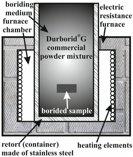
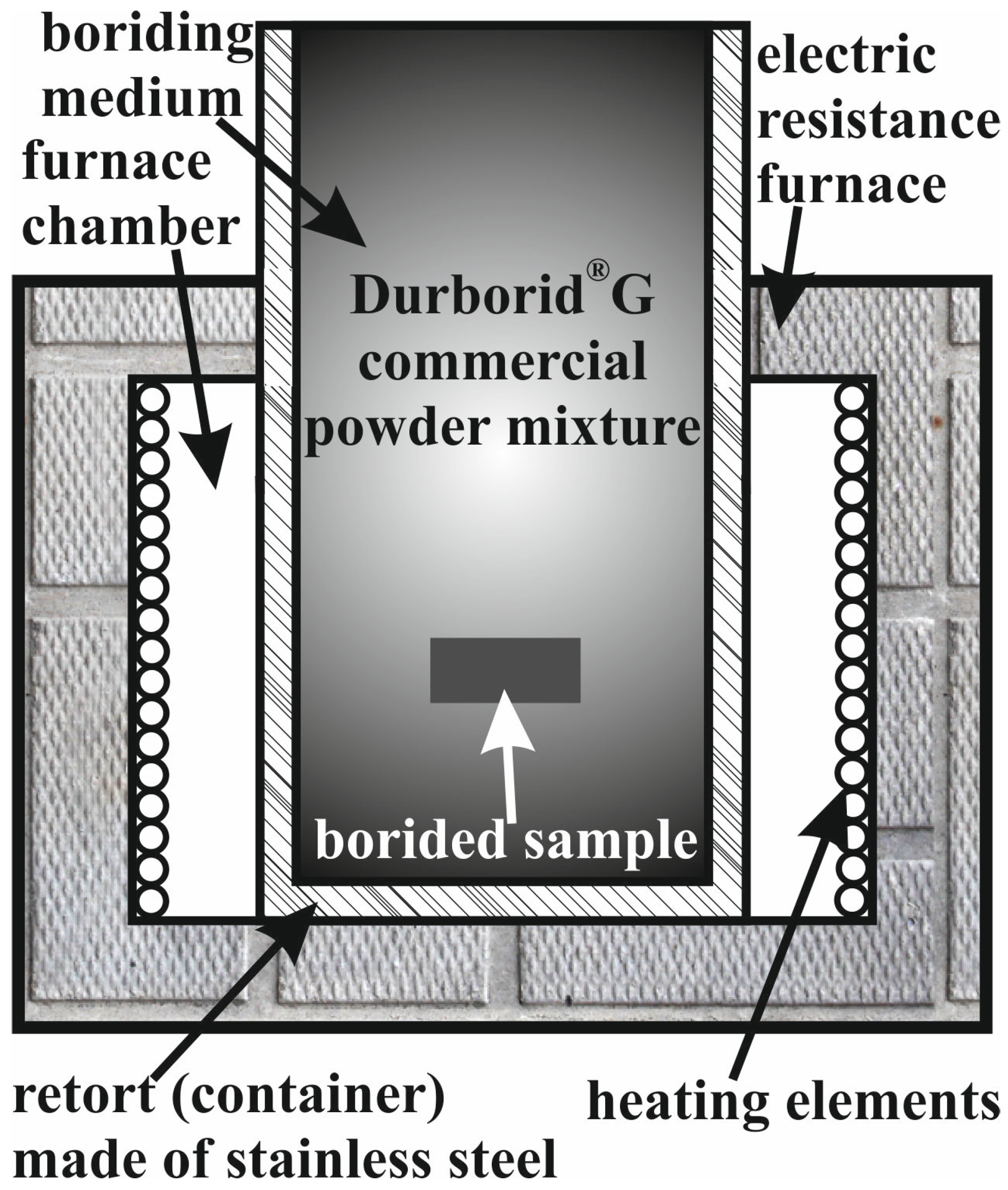
Before diffusion boriding, washing with distilled water, degreasing with acetone, and rinsing with alcohol were carried out in order to prepare the surface of the samples. The boriding process was carried out in a commercial Durborid®G powder mixture (Durferrit GmbH, Mannheim, Germany). It was only reported that boron carbide (B4C) was used as a boron source in this powder mixture [26]. The samples were powder-pack borided using a unique technique with an open retort [27]. The corresponding device is shown in Figure 1. This technique was used for the first time for the formation of boride layers on powder steel. The open retort, made of stainless steel, was tube-shaped with a closed bottom. The tube was filled with the Durborid®G powder mixture, in which a K190 steel sample was placed without an additional sealing. Next, the tube was placed into the chamber of an electric resistance furnace so that its upper part extended outside the furnace (see Figure 1). As a consequence, the powder mixture outside the furnace (in the extended part of the retort) acted as a natural seal. The temperature of the boriding medium in this upper part of the retort was so low that the powder mixture as well as the samples were protected against oxidation. At the same time, the gases generated in the bottom part of the retort resublimated in the upper cold part. Hence, the escape of these gases beyond the retort was impossible [1,27].
Figure 1.
Scheme of the device used for powder-pack boriding with an open retort.
The diffusion boriding parameters were selected so that the most typical temperature range for the powder-pack process of the steel was used, i.e., 900–1000 °C [1]. The process duration was chosen to be as short as possible, not exceeding 9 h. Therefore, the powder-pack boriding parameters were as follows: temperatures of 900 °C (1173 K), 950 °C (1223 K), and 1000 °C (1273 K), and durations of 3, 6, and 9 h. The position of the borided sample in the tube-shaped retort was selected so that its temperature corresponded to that assumed. The sample temperature was verified using an additional thermocouple. In all cases, powder-pack boriding was carried out at one fixed temperature for one specific period of time. Increasing the temperature and extending the process time resulted in thicker diffusion layers. It is difficult to determine which of the boriding parameters (temperature or time) is more influential. The same borided layer thickness can be achieved at a lower temperature and a longer process time, as well as at a higher temperature and a shorter process time.
2.3. Microstructure and Property Characterization
The phase analysis of the borided layers was carried out using X-ray diffraction (XRD). A PANalytical EMPYREAN computer-controlled X-ray diffractometer (Malvern Panalytical Ltd., Almelo, The Netherlands) was used. CuKα radiation (λ = 0.154 nm) with an angle of 2θ in the range of 30° to 100° was applied in this study.
For microscopic observations, metallographic specimens were prepared. The borided samples were cut perpendicular to the surface of the layers produced. The cut samples were then hot-mounted in a conductive resin, ground using SiC abrasive paper, and finally polished with a 0.05 µm aluminum oxide paste. A typical nital solution ((5% HNO3 solution in ethyl alcohol) was used as an etching reagent in order to expose the microstructure. The microstructural observations were carried out using the KEYENCE VHX-7000 (KEYENCE INTERNATIONAL, Mechelen, Belgium) digital microscope. For additional characterization of the microstructure, a MIRA 3 (TESCAN, Brno, Czech Republic) scanning electron microscope (SEM) equipped with an energy dispersive spectrometer (EDS) from Oxford Instruments (Ultim Max 65, High Wycombe, UK) was used. The concentrations of the elements characteristic of the microstructure obtained (Fe, Cr, V, C, and B) were measured in the cross-section of the surface layer. The detection of light elements such as boron and carbon using EDS has inherent limitations, particularly with respect to quantitative accuracy. The EDS detector operated at an accelerating voltage of 10 kV and an emission current of 173 μA. The measurements were carried out using line scan analysis and EDS mapping with a low working distance and an extended acquisition time in order to improve the detectability of light elements. The EDS results presented in this work should be considered as supportive qualitative/semi-quantitative evidence, and they were interpreted together with the XRD and microstructural observations rather than as definitive quantitative confirmation of boron and carbon concentrations. It is obvious that WDS analysis would provide more reliable quantitative information for boron and carbon concentrations.
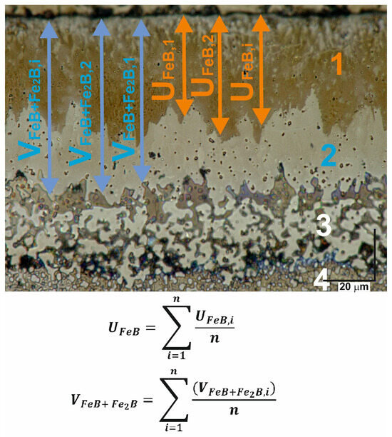
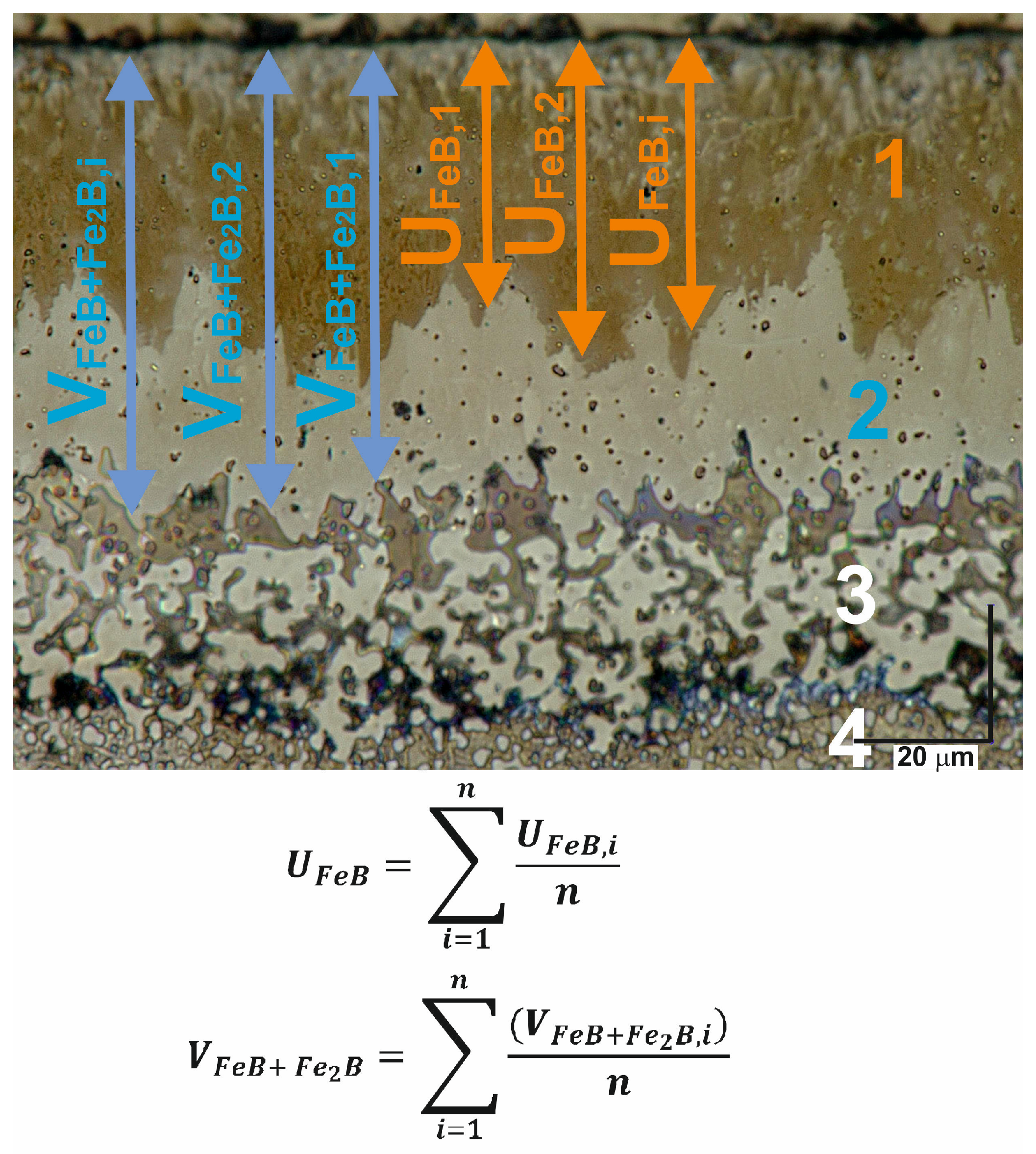
The thicknesses of the borided layers were determined based on about 200 measurements. Then, the average value was calculated. These thicknesses were measured at different locations on the cross-sections of metallographic specimens. The needle-like morphology of the borides was the main difficulty during these measurements. The thicknesses of the FeB boride zone and the total layer thicknesses (FeB + Fe2B) were determined using the special procedure proposed by Kunst and Schaaber and described in detail in [2]. KEYENCE digital images of the borided layers at different boriding parameters were used for measurements. The thicknesses of the FeB zone and the entire FeB + Fe2B zone were measured at constant distance intervals. This way, the needle-like morphology of borides was taken into account. The measurement methodology is shown in Figure 2.
Figure 2.
Methodology for measurements of the thicknesses of the FeB zone (UFeB) and FeB + Fe2B zone (VFeB+Fe2B) in boride layers; 1—FeB zone; 2—Fe2B zone; 3—transition zone with increased carbon content; 4—substrate material.
The microhardness profiles across the boride layers were determined using a Micromet II hardness tester (Buehler, Leinfelden-Echterdingen, Germany) equipped with a Vickers diamond indenter. The load was equal to 50 gf (0.49 N), and a peak-load contact of 15 s was used.
3. Results and Discussion
3.1. Microstructure of Substrate Material
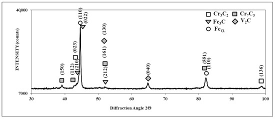
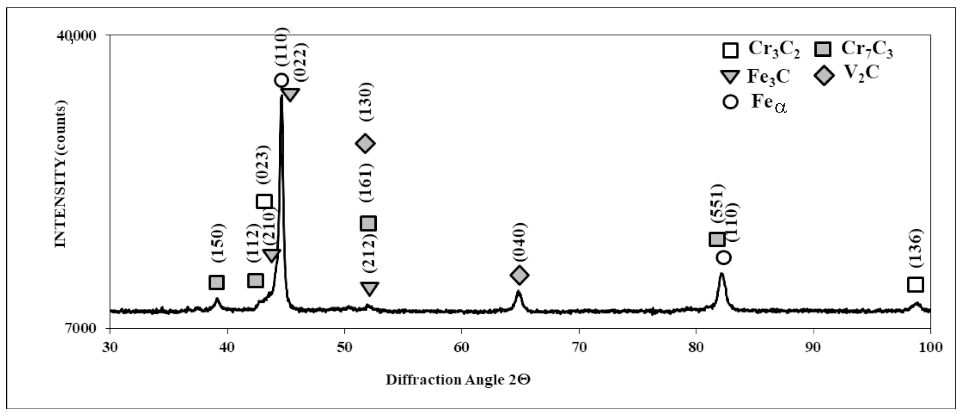
The XRD patterns of the substrate material, i.e., BÖHLER K190 MICROCLEAN® ledeburitic chromium steel manufactured by powder metallurgy and delivered in a soft-annealed condition, are shown in Figure 3. The phase analysis revealed the presence of the Feα phase (ferrite) constituting the soft matrix and hard chromium (Cr7C3, Cr3C2), vanadium (V2C), and iron (Fe3C) carbides within this matrix. These results corresponded well with those of paper [24], in which ferrite as well as chromium and vanadium carbides (Cr7C3, V4C3) were identified.
Figure 3.
XRD patterns of soft-annealed K190 steel.
3.2. Microstructure of Borided Layers
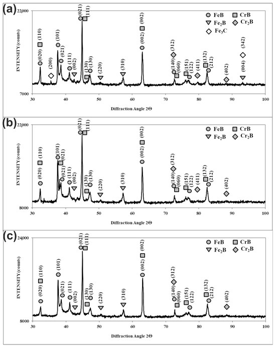
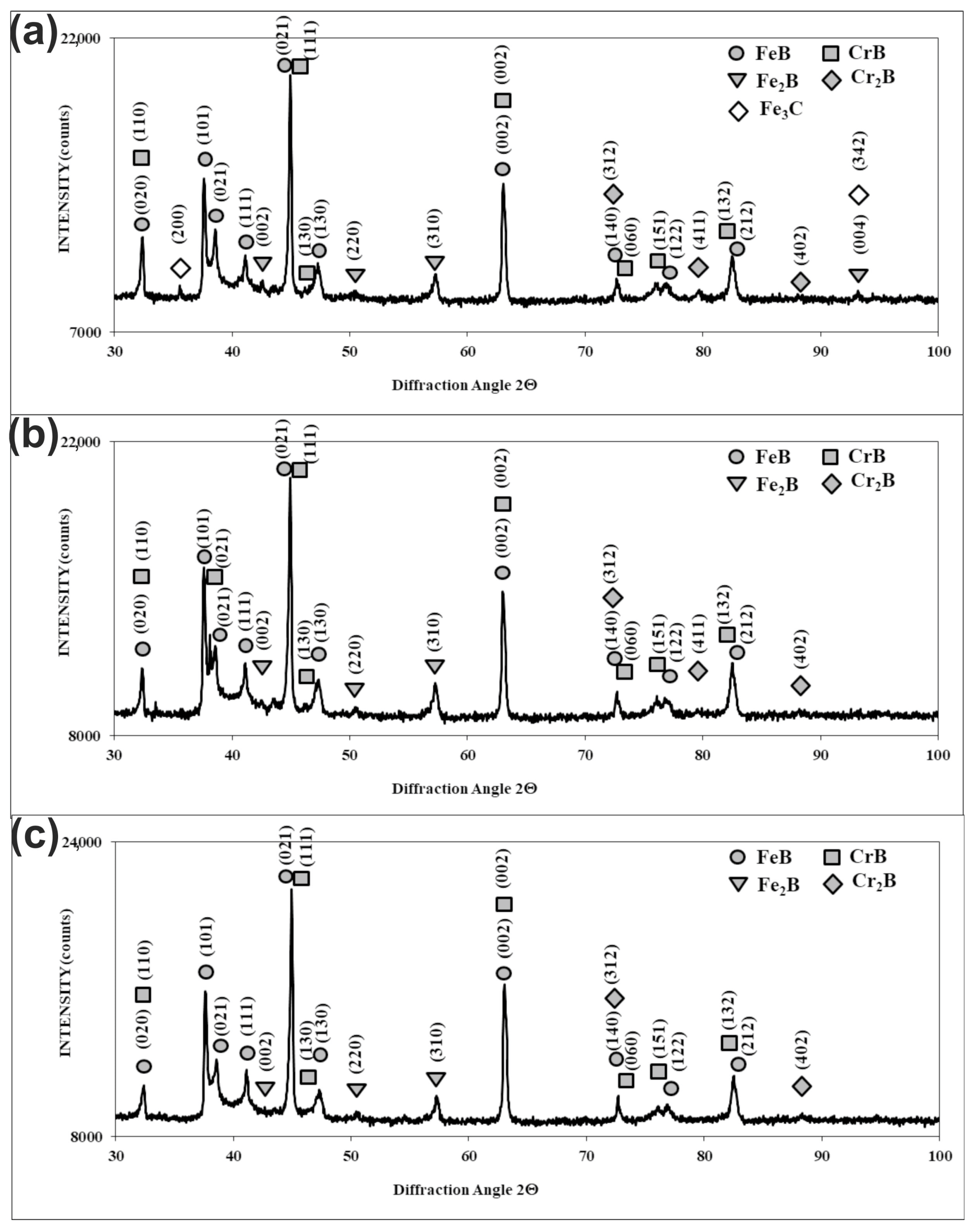
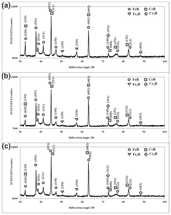
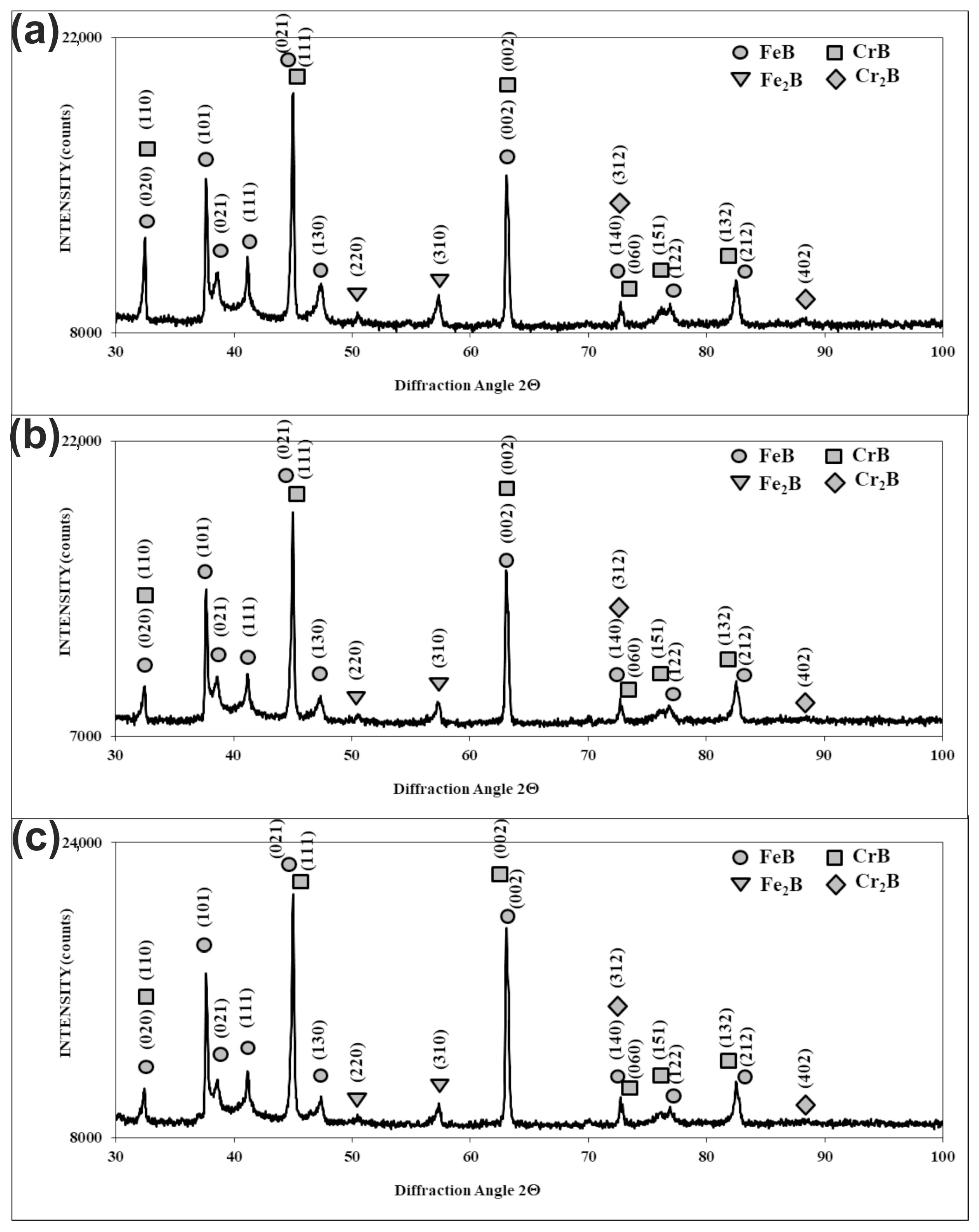
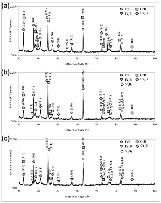
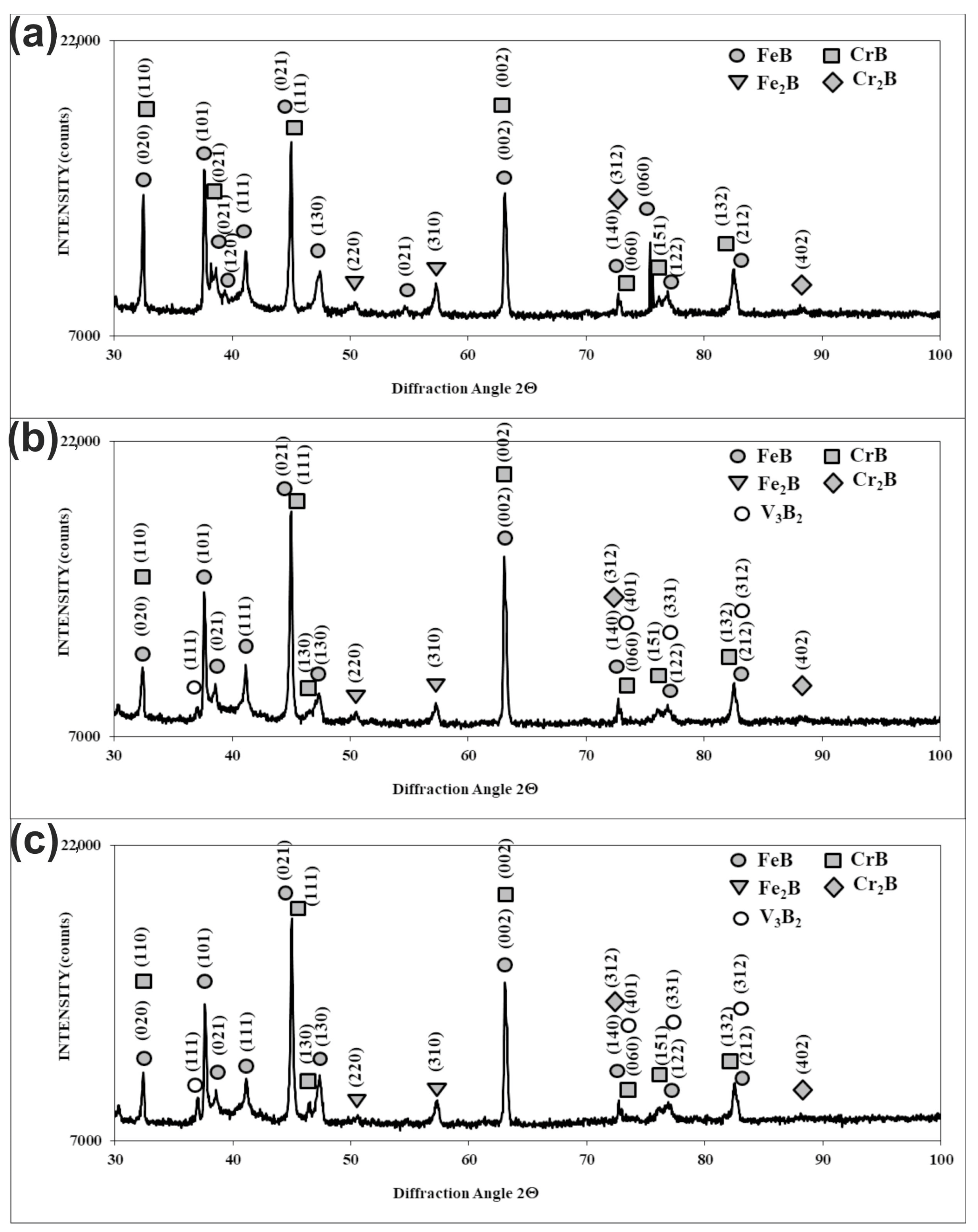
The X-ray diffraction patterns (Figure 4, Figure 5 and Figure 6) of powder-pack borided Böhler K190 steel confirmed the presence of dual-phase layers composed mainly of two types of iron borides: FeB and Fe2B. Due to the high content of chromium in the substrate material (12.50 wt.%), CrB and Cr2B chromium borides were identified in the boride layer. For the layer produced at the lowest temperature (1173 K) and shortest duration (3 h), because of its relatively low thickness, the presence of Fe3C carbides was detected, probably occurring in the transition zone. In this case, the XRD radiation also penetrated this zone. To summarize, the two main zones occurred in the microstructure of the powder-pack borided layers produced on K190 steel: the outer FeB zone and the Fe2B zone below the first one. These zones contained mainly FeB and Fe2B borides, respectively. Additionally, CrB and Cr2B borides probably appeared in these zones. It is also possible that chromium could have replaced iron in the borides, providing complex borides (Fe,Cr)B or (Fe,Cr)2B in the microstructure [17,19]. A Rietveld refinement of the XRD patterns could provide additional quantitative insight into the evolution of lattice parameters, possible Cr incorporation into the FeB/Fe2B phases, and phase occupancy as a function of boriding time. However, at the present stage, a reliable Rietveld analysis could not be performed due to the limited quality/resolution of the available diffraction data and the significant overlap of reflections from the boride phases and substrate contributions. Under these conditions, the refinement results would not be sufficiently robust to support quantitative conclusions regarding Cr occupancy. The detailed Rietveld refinement combined with high-resolution XRD measurements will be the subject of future work. In the current study, the mechanistic interpretation is based on phase identification, microstructural observations, and hardness evolution, which together consistently indicate the formation and growth of FeB/Fe2B-based layers with Cr participation. The appearance of complex borides could have a positive effect on some of their properties. It was indicated in paper [28] that elements such as Ti, V, Cr, Co, Ni, and Cu enhanced the ductility of the Fe2B borides but did not change the intrinsic brittle nature of this phase. The higher boriding temperature and longer duration of the process resulted in an increase in the thickness of the outer FeB zone. This caused the peaks from the FeB and CrB borides to dominate in the XRD patterns. Because of the high vanadium content in the steel considered, vanadium borides could occur in the boride layers. However, the V3B2 vanadium borides were identified only at longer boriding times at the highest temperature of 1273 K (Figure 6).
Figure 4.
XRD patterns of powder-pack borided Böhler K190 steel at 1173 K: (a) for 3 h, (b) for 6 h, (c) for 9 h.
Figure 5.
XRD patterns of powder-pack borided Böhler K190 steel at 1223 K: (a) for 3 h, (b) for 6 h, (c) for 9 h.
Figure 6.
XRD patterns of powder-pack borided Böhler K190 steel at 1273 K: (a) for 3 h, (b) for 6 h, (c) for 9 h.
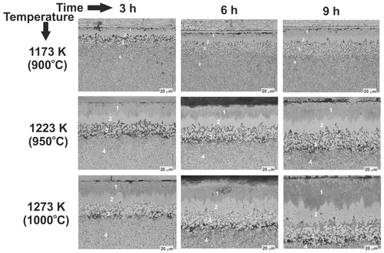
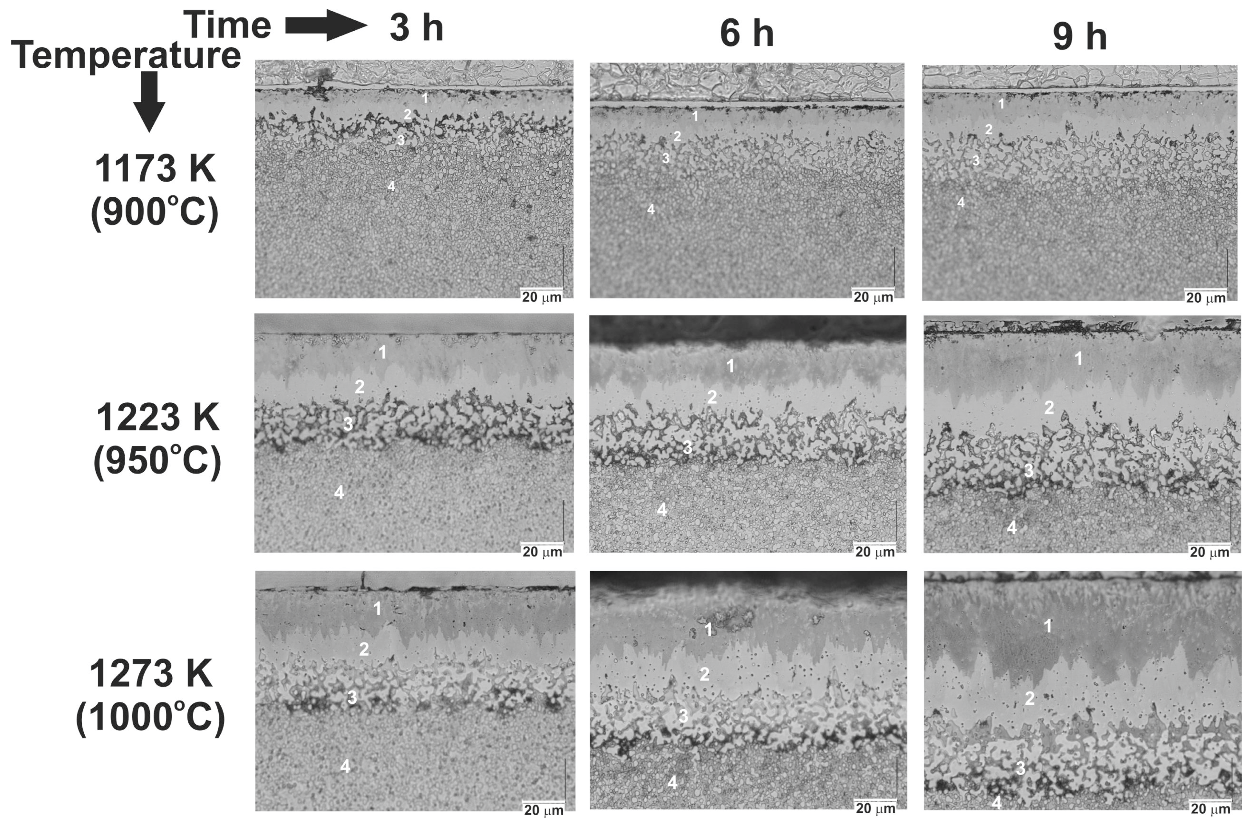
The microstructure of the boride layers was analyzed using a digital microscope. The obtained images of the microstructure for all the parameters used (temperature and time) are shown in Figure 7. All the powder-pack borided layers consisted of three zones: the outer FeB zone (1), the Fe2B zone below the first one (2), and the transition zone (3). Beneath the transition zone, there was the substrate material (4). The FeB zone contained FeB and CrB borides and possibly complex (Fe,Cr)B borides. In the Fe2B zone, Fe2B and Cr2B borides and, possibly, complex (Fe,Cr)2B borides, occurred. Ledeburitic chromium high-carbon steel (K190) was used as the substrate material. The high carbon content in the substrate material led to the formation of a transition zone with a significantly higher carbon content compared to the substrate. This can be explained by the displacement of carbon atoms toward the core, following the boron diffusion front [1]. This resulted in a significantly higher percentage of iron, chromium, and vanadium carbides in this region (see Figure 7). It is easy to see that the average total thickness of the two-phase boron layer (FeB + Fe2B) was greater at higher temperatures and longer process times. Obviously, the same dependence applied to the outer FeB zone. A very irregular boundary between the Fe2B zone and the transition zone was characteristic of the microstructure of K190 borided steel. The high percentage of carbides in the transition zone was the reason for this situation.
Figure 7.
Microstructure of powder-pack borided Böhler K190 steel using various temperatures and durations; 1—FeB zone, 2—Fe2B zone, 3—transition zone, 4—substrate material.
The images of the microstructure obtained using a digital microscope (Figure 7) provided basic information about the zones occurring in the borided K190 steel. Based on these images, the thicknesses of the outer FeB zone as well as that of the total layer (FeB + Fe2B) were measured. The FeB + Fe2B layers, produced at a temperature of 1173 K (900 °C), were characterized by an average thickness of 14.13 ± 2.97 µm to 22.10 ± 2.52 µm with increasing processing times of 3 h to 9 h. A further increase in the boriding temperature up to 1223 K (950 °C) resulted in the formation of a layer with a thickness range of 23.47 ± 2.17 µm to 40.66 ± 2.18 µm, depending on the time of boriding. The highest temperature of the process, i.e., 1273 K (1000 °C), ensured the highest thickness of the layer from 33.71 ± 2.34 µm to 65.49 ±2.65 µm for boriding times of 3 h and 9 h, respectively. The complete results of the measurements of the thicknesses of the boride layers are shown in Table 2.
Table 2.
The measurements of the thicknesses of boride layers depending on the boriding parameters.
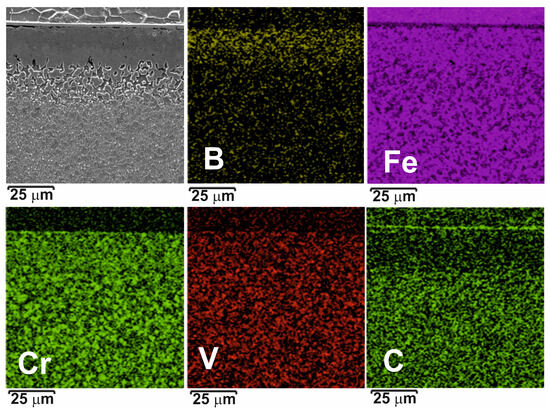
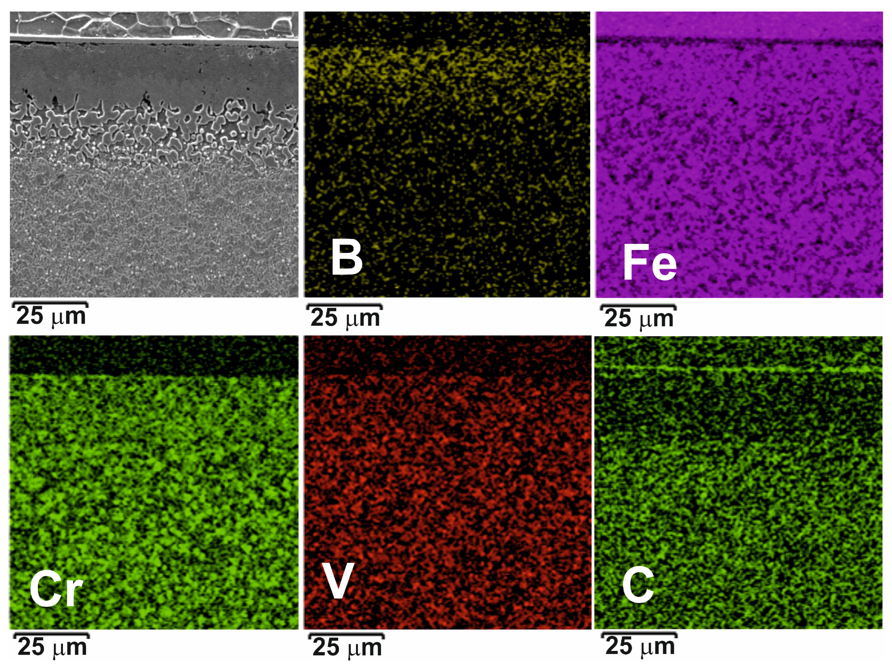
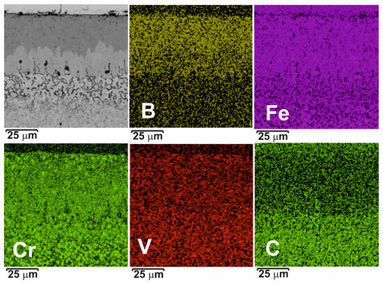
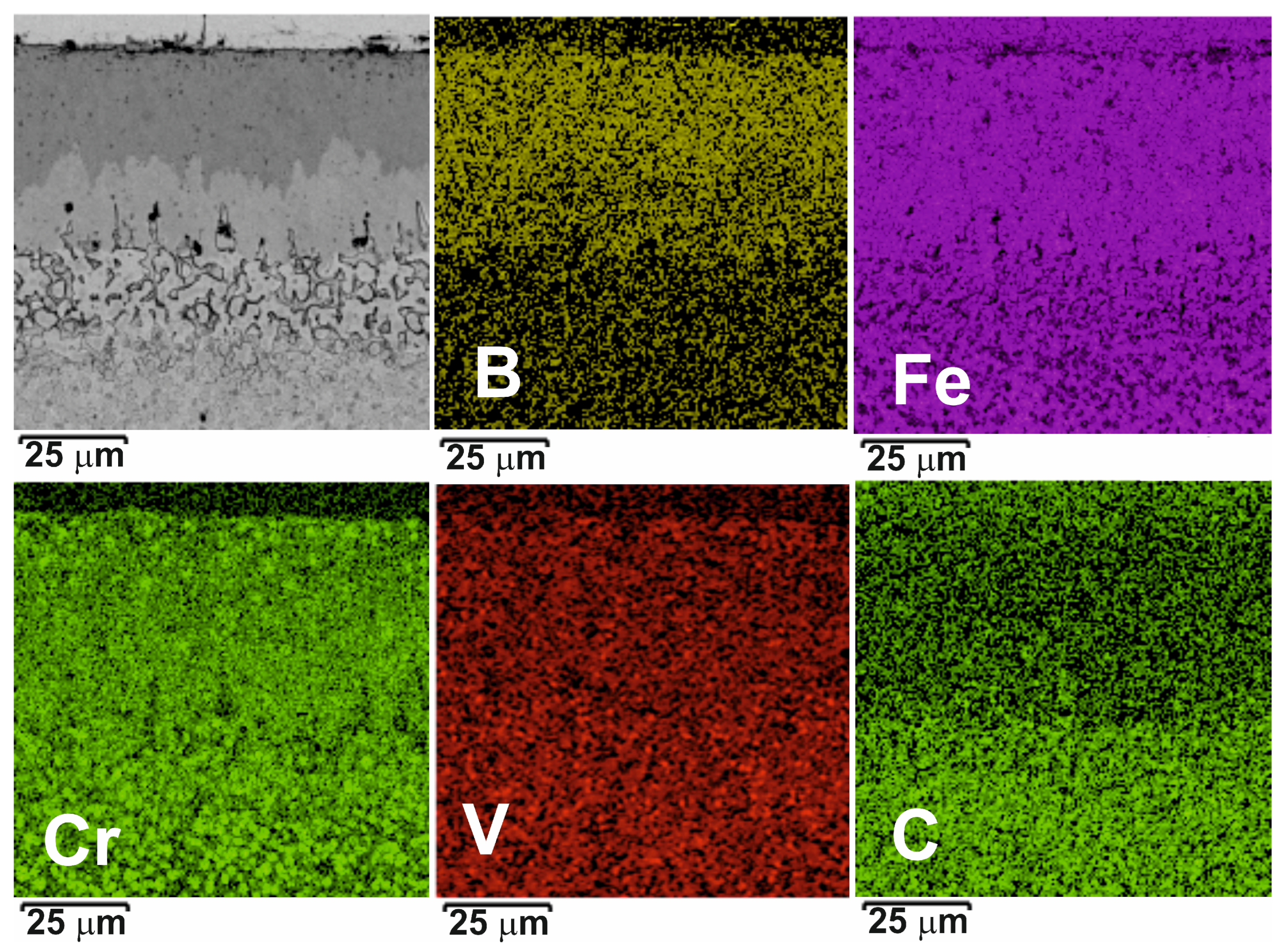
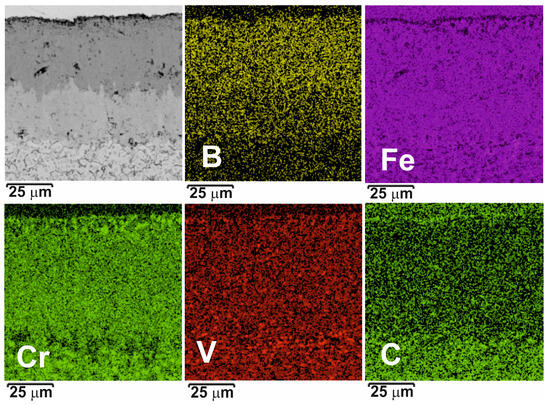
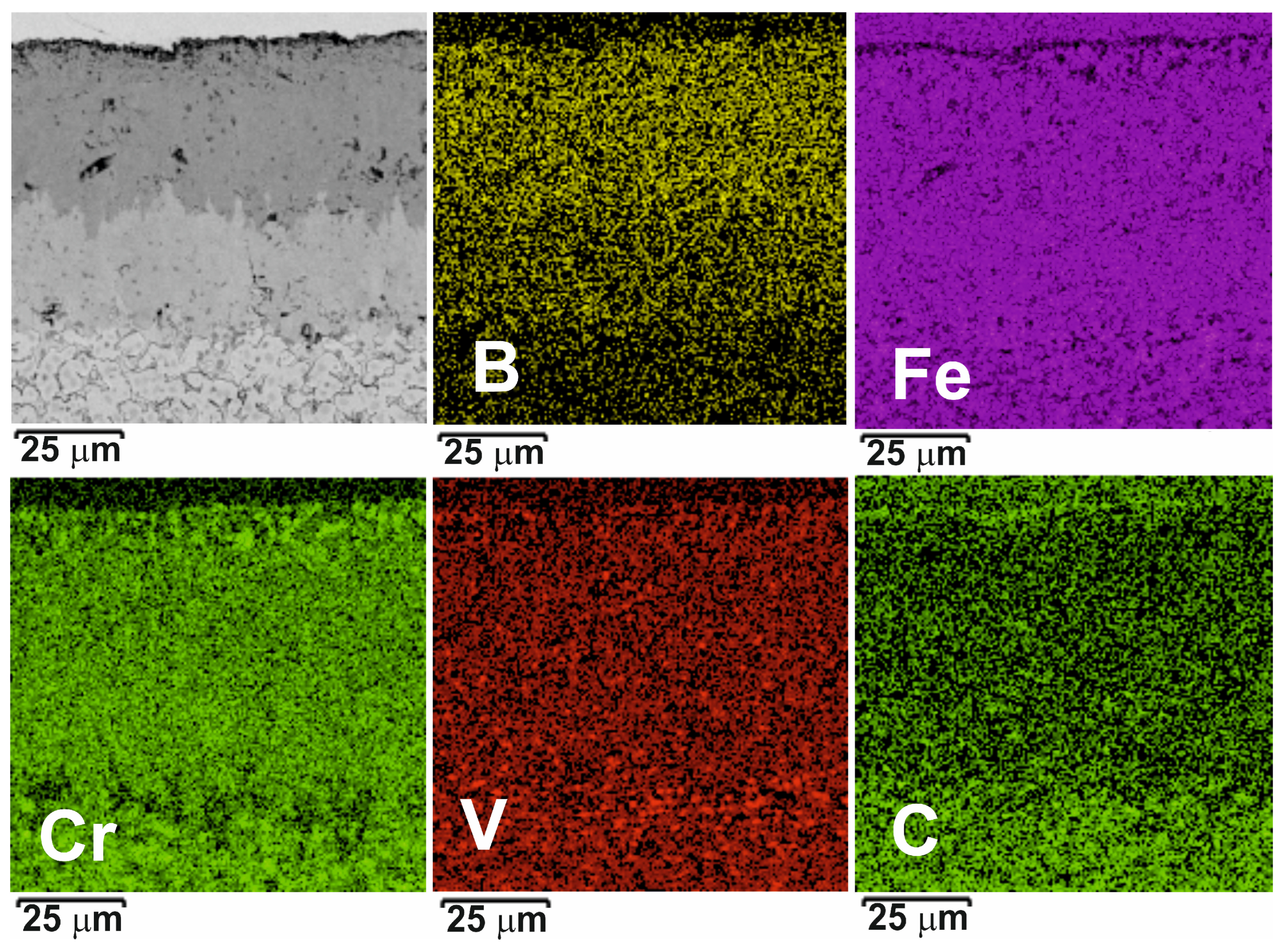
The distribution of main elements characteristic of borided Böhler K190 ledeburitic chromium steel (B, Fe, Cr, V, and C) was investigated using EDS mapping (Figure 8, Figure 9 and Figure 10). The samples borided at 1173 K (900 °C), 1223 K (950 °C), and 1273 K (1000 °C) for the longest duration (9 h) were analyzed. An increased concentration of boron and a diminished carbon concentration were clearly visible in the boride layers. An uneven distribution was observed for the metallic elements. This may be due to the presence of fine carbides not only in the transition zone and in the substrate material, but also in the FeB and Fe2B zones, although phase analysis only detected Fe3C iron carbide in the thinnest layer obtained at 1173 K for 3 h, and probably in the transition zone.
Figure 8.
BSE image of microstructure and results of EDS mapping for powder-pack borided Böhler K190 steel at 1173 K for 9 h.
Figure 9.
BSE image of microstructure and results of EDS mapping for powder-pack borided Böhler K190 steel at 1223 K for 9 h.
Figure 10.
BSE image of microstructure and results of EDS mapping for powder-pack borided Böhler K190 steel at 1273 K for 9 h.
K190 steel is a type of ledeburitic steel. This means that after slow cooling from the boriding temperature, its microstructure should consist of transformed ledeburite, fine pearlite, and secondary carbides. The ledeburite is a transformed eutectic mixture including fine pearlite as well as primary and secondary carbides. It was assumed that such a microstructure could appear with chromium, vanadium, and iron carbides in the areas below the Fe2B zone.
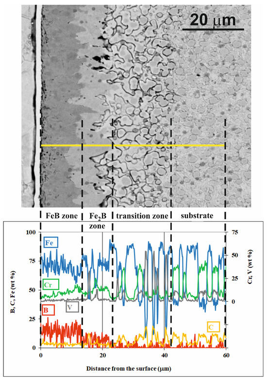
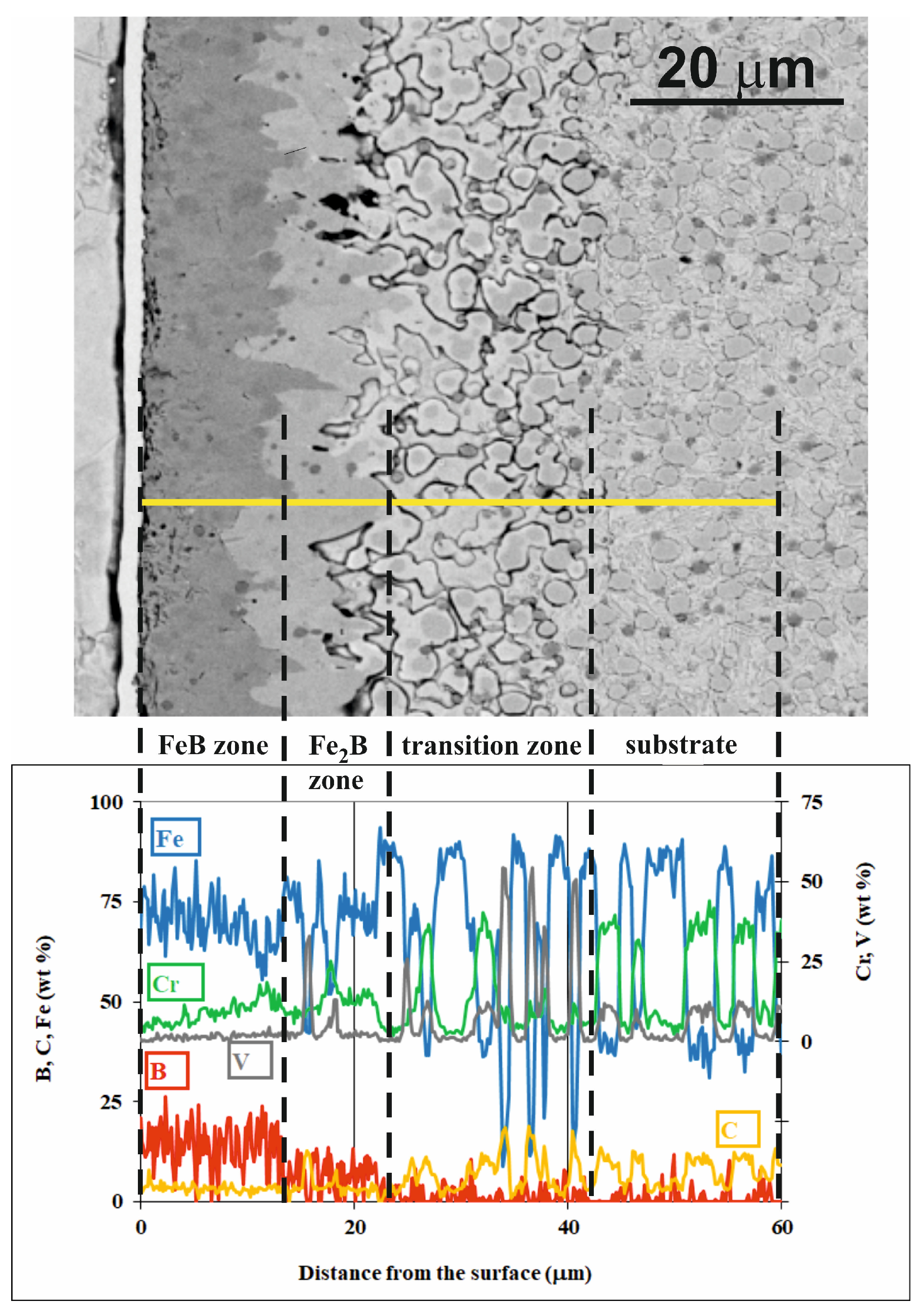
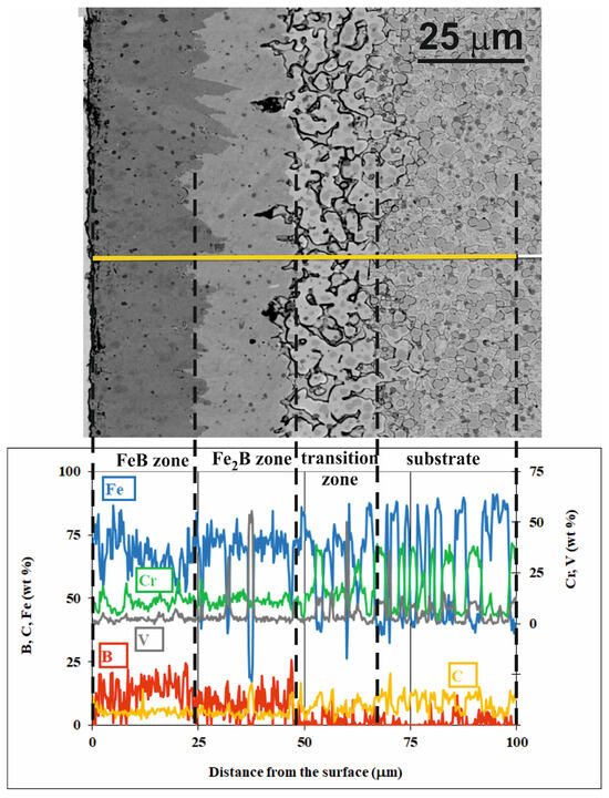
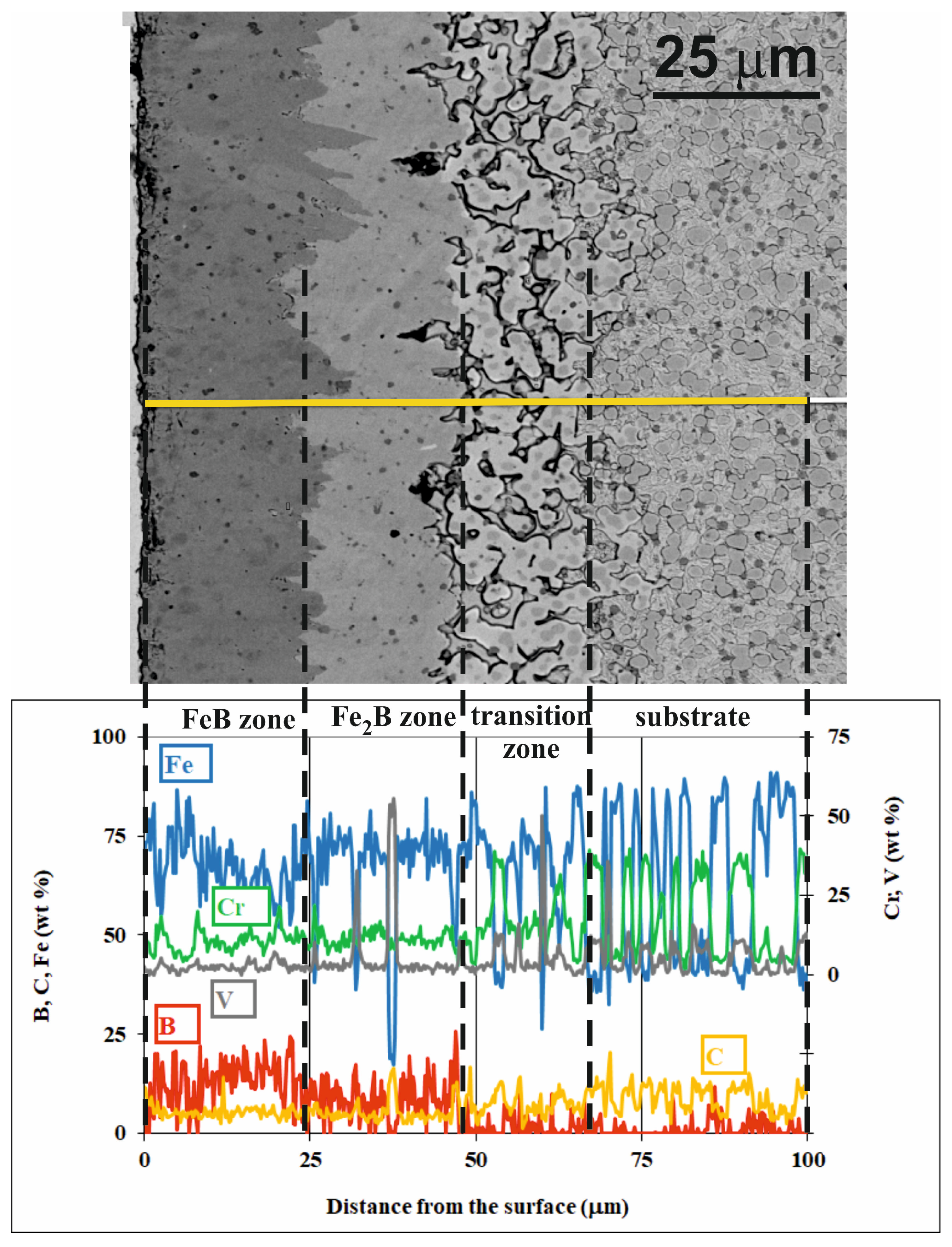
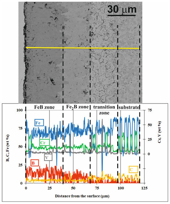
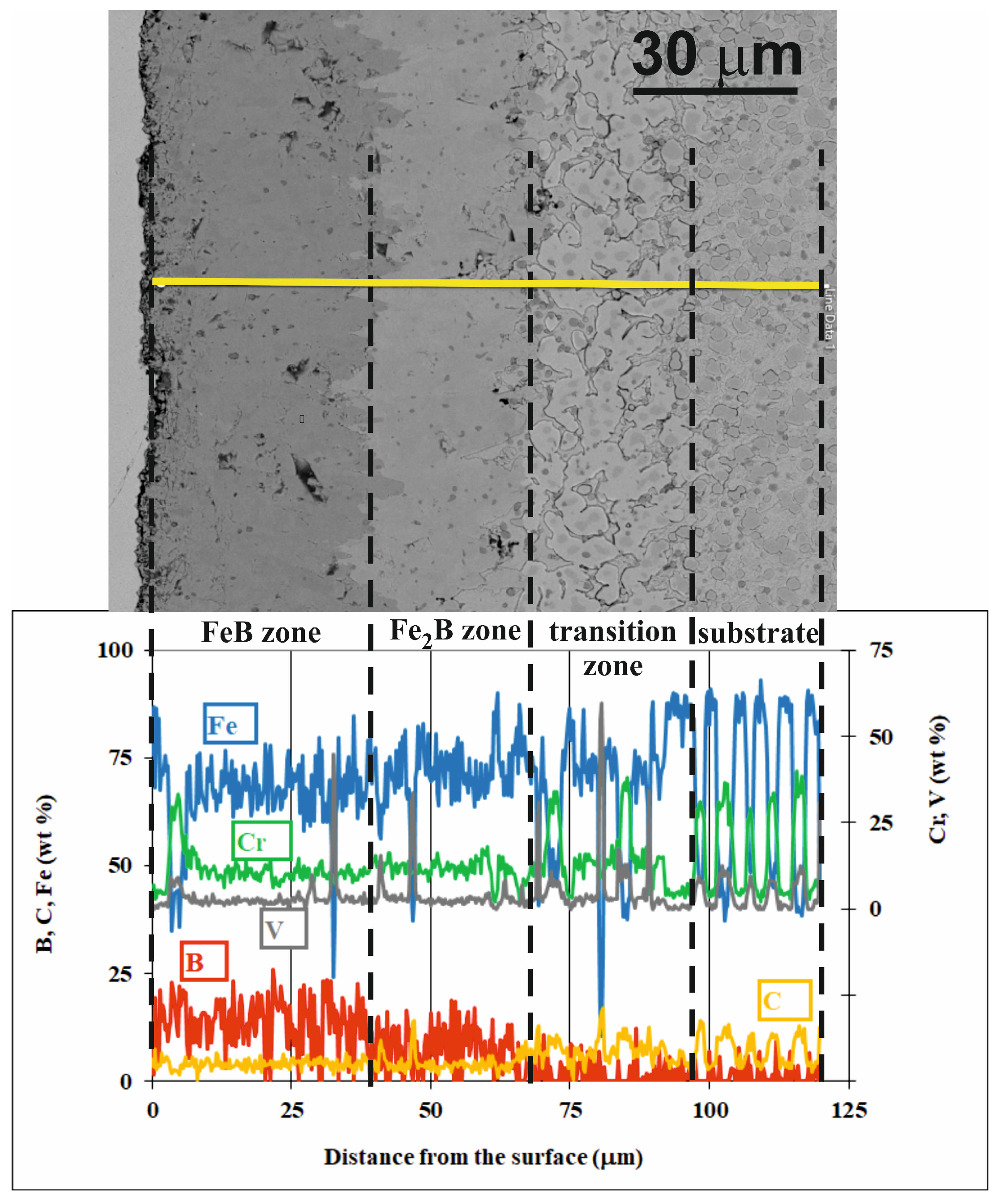
Line EDS X-ray microanalysis was employed in order to better characterize the phases that occurred in the cross-sections of the borided layers (Figure 11, Figure 12 and Figure 13). This investigation was also performed for the samples borided at temperatures of 1173 K (900 °C), 1223 K (950 °C), and 1273 K (1000 °C) for 9 h. These boride layers were selected because they showed the highest thickness at each temperature. Simply, in these cases, the differences in chemical composition were the most clearly visible. The concentrations of iron, chromium, vanadium, boron, and carbon were measured along a straight line (Figure 11, Figure 12 and Figure 13) through all the zones visible in the microstructure: the FeB zone, the Fe2B zone, the transition zone, and the substrate. The measurement line is marked in yellow in these figures.
Figure 11.
BSE image of microstructure and results of line X-ray microanalysis for powder-pack borided Böhler K190 steel at 1173 K for 9 h.
Figure 12.
BSE image of microstructure and results of line X-ray microanalysis for powder-pack borided Böhler K190 steel at 1223 K for 9 h.
Figure 13.
BSE image of microstructure and results of line X-ray microanalysis for powder-pack borided Böhler K190 steel at 1273 K for 9 h.
The concentration of boron in all the cross-sections of borided K190 steel (Figure 11, Figure 12 and Figure 13) changed depending on the distance from the surface. In general, the increase in distance from the surface caused a decrease in the concentration of boron. The highest values of boron content were observed in the outer FeB zone, in which FeB iron borides predominated in the microstructure. The measured values of boron concentration in this zone oscillated around the equilibrium boron content in the FeB phase (16.23 wt.%). At certain distances from the surface, local maxima of the boron concentration occurred simultaneously with local maxima of the chromium concentration and local minima of the iron concentration. At some distances from the surface, local maxima of the boron concentration corresponded to local maxima of the chromium concentration and local minima of the iron concentration. This indicated the possible presence of CrB chromium borides in the boride layer. The CrB phase is characterized by a higher content of boron compared to FeB iron borides. According to the phase analysis (Figure 4, Figure 5 and Figure 6), CrB borides could occur in these areas. It was also possible that, in this zone, the complex (Fe,Cr)B phase appeared. Simultaneously, a similar situation was observed in the case of vanadium concentration. The local maxima of this element were accompanied by local minima of the iron concentration. The boron content in vanadium boride is lower when compared to the FeB phase. However, sometimes, local maxima of the boron concentrations were observed in this case. The only vanadium boride identified by phase analysis, and only at longer boriding times at the highest temperature of 1273 K (Figure 6), was the V3B2 phase. Hence, this vanadium boride could occur in these areas.
The next Fe2B zone (Figure 11, Figure 12 and Figure 13) was characterized by clearly lower concentrations of boron because of the predominant presence of the Fe2B phase with an equilibrium content of boron of 8.83 wt.%. The measured values of boron concentration oscillated around this equilibrium value. Also, in some areas of this zone, local minima of iron concentration were accompanied by local maxima of chromium or vanadium concentration. This indicated the presence of Cr2B chromium borides and V3B2 vanadium borides in the Fe2B zone according to the XRD pattern obtained (Figure 4, Figure 5 and Figure 6). There was also a possibility of the occurrence of the complex (Fe,Cr)2B phase in this zone. The concentration of carbon in the boride layer (FeB and Fe2B zones) was relatively low (Figure 11, Figure 12 and Figure 13), confirming that carbon does not dissolve in iron borides.
A further increase in the distance from the surface caused a strong decrease in boron concentration as a consequence of changes in the microstructure, i.e., the appearance of the transition zone (Figure 11, Figure 12 and Figure 13). The strong fluctuations in the concentrations of metallic elements (Fe, Cr, V) were clearly visible in the transition zone. This was caused by a significantly increased carbon concentration in this zone (see Figure 11, Figure 12 and Figure 13) and the accumulation of large amounts of chromium, vanadium, and iron carbides. These could be chromium (Cr7C3, Cr3C2), vanadium (V2C), and iron (Fe3C) carbides, which were found in the steel in its initial state (Figure 3). However, the formation of other types of carbides in this zone cannot be ruled out. The BSE microstructure images show a small number of pores in the borided layers, especially in the Fe2B zones. These are likely locations where carbides were chipped off from the metallographic specimens during polishing. This has been observed previously in the boriding of another high-carbon steel [29].
3.3. Mean Diffusion Coefficient Model
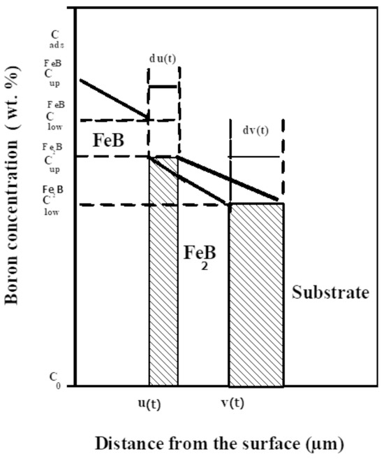
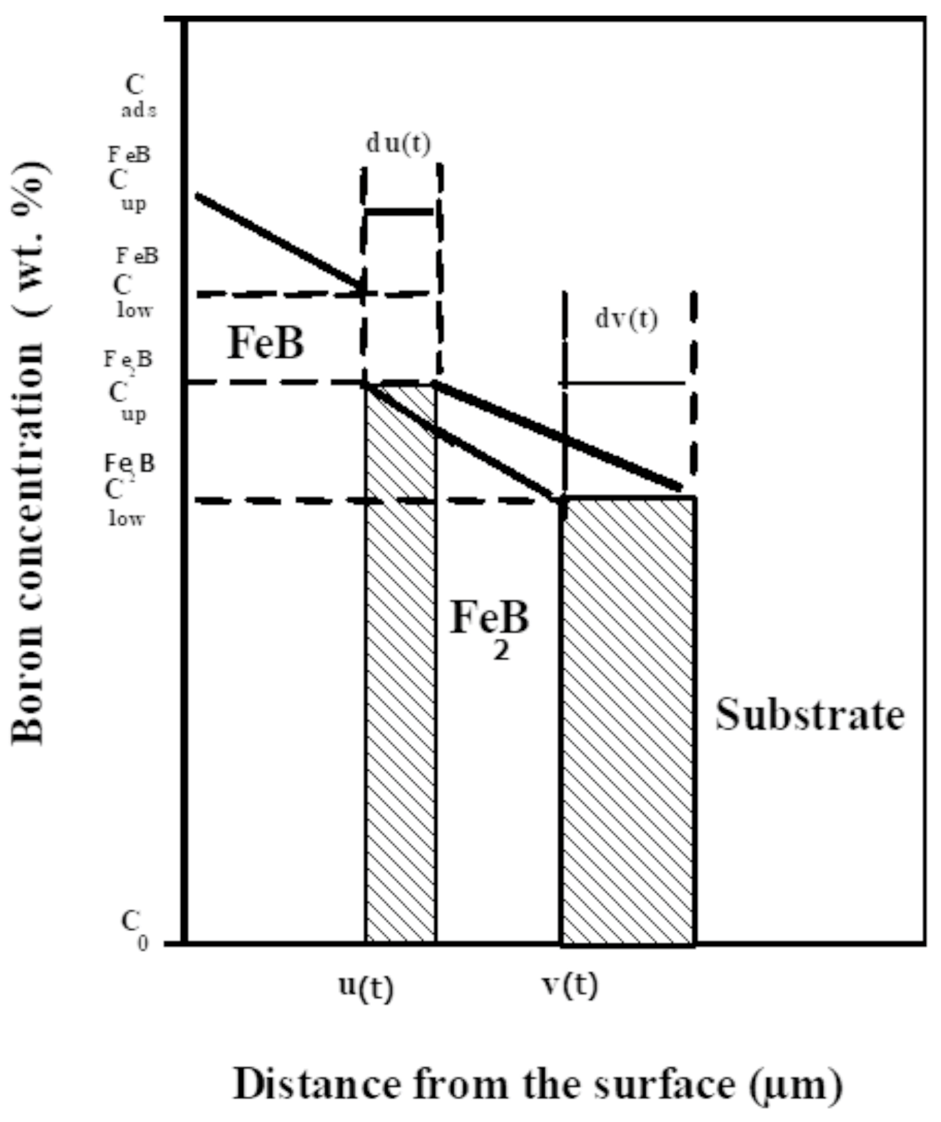
The mean diffusion coefficient model [30,31] has already been implemented for studying the boron diffusion kinetics in AISI D2 and AISI H13 steels. In this work, it was applied to the boriding kinetics of Bohler K190 steel. Figure 14 describes a schematic evolution of B concentration profiles, which are linear along the FeB and Fe2B layers, with no occurrence of boride incubation times.
Figure 14.
Schematic illustration of B concentration profiles along the bilayer (FeB/Fe2B) [29].
The upper and lower B concentrations in FeB are (=16.40 wt.%B) and (=16.23 wt.%B), respectively, while those in Fe2B are (=9 wt.%B) and (=8.83 wt.%B), respectively [31]. represents the amount of B atoms adsorbed on the material surface [32]. The variable u refers to the thickness of the FeB layer, while v refers to the thickness of the bilayer (FeB/Fe2B). is the maximum B solubility in the matrix, which is 35 × 10−4 wt.% B [33]. The influence of time on the thickness of the FeB layer is expressed by Equation (1):
The parameter k’ is the parabolic growth constant at the first interface. The thickness of the bilayer (FeB/Fe2B) is expressed by Equation (2):
where k refers to the parabolic growth constant at the second interface.
According to the mean diffusion coefficient model [30,31] for the biphased system, the B diffusivities in FeB and Fe2B are then expressed by:
and
with
and
3.4. Calculation of Boron Diffusivities in Iron Borides
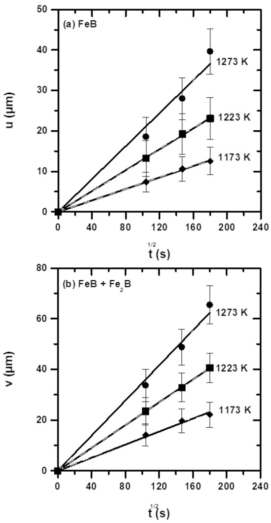
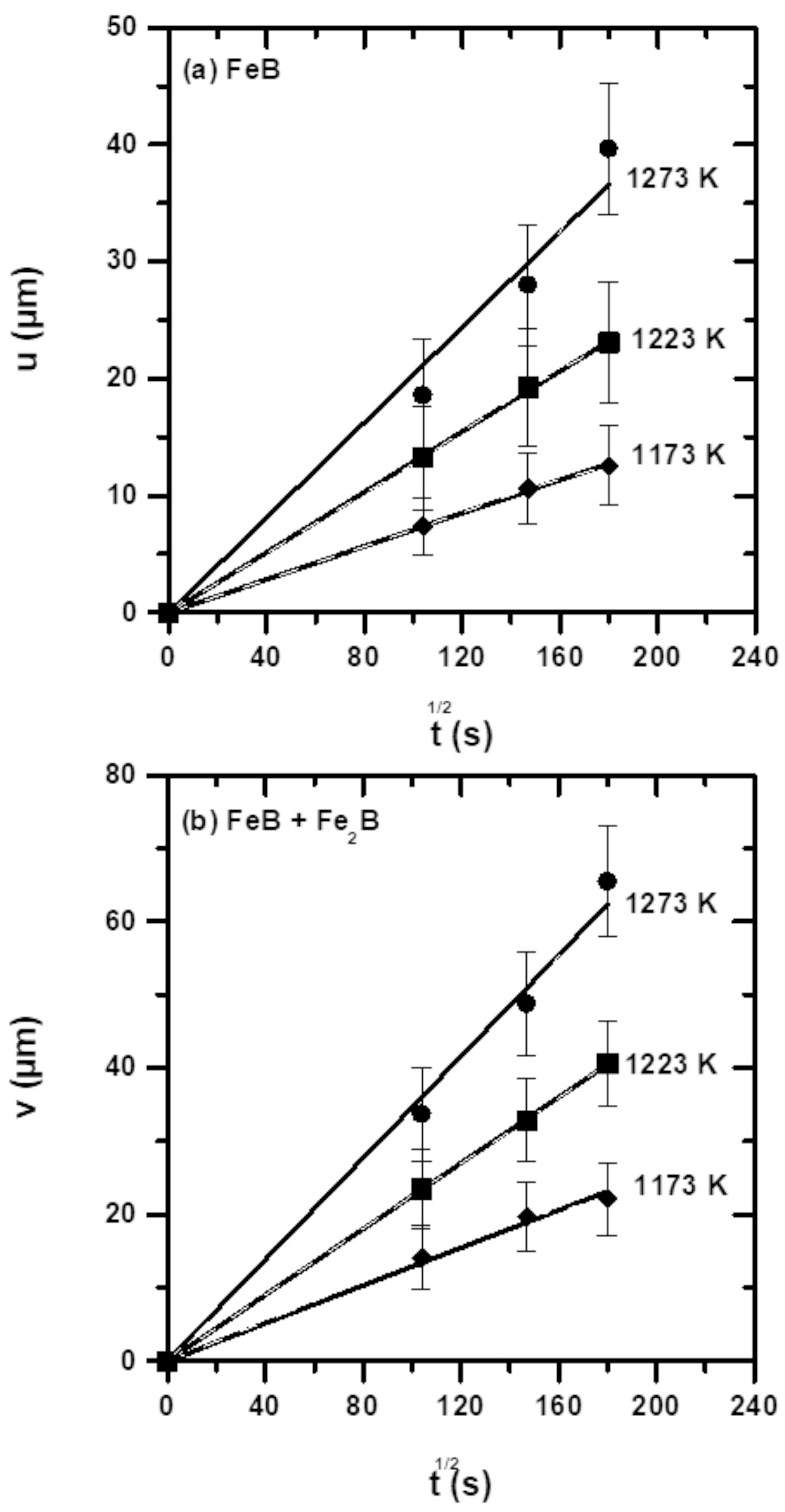
To evaluate the boron diffusivities in the FeB and Fe2B zones, it is necessary to plot graphs of the layer thickness as a function of the boriding time within the selected temperature range. Figure 15 shows the layer thicknesses versus the square root of time at increasing temperatures based on the results of the measurements of layer thicknesses (Table 2). The boride layers grow according to the parabolic law, as reflected in the graphs in Figure 15. Table 3 compiles the experimental parabolic growth constants, obtained as the slopes of the straight lines in Figure 15.
Figure 15.
Time-dependent growth of layer thicknesses at different temperatures: (a) FeB and (b) (FeB + Fe2B).
Table 3.
Parabolic growth constants for different temperatures determined experimentally.
Table 4 presents the boron diffusivities in FeB and Fe2B, determined using Equations (3) and (4) within the range of 1173–1273 K.
Table 4.
Boron diffusion coefficients in FeB and Fe2B, calculated using Equations (3) and (4).
The B diffusivity expressions in the iron borides were derived by fitting the data from Table 4 to the Arrhenius equations. Accordingly, Equations (5) and (6) were obtained, with determination coefficients close to unity.
where R = 8.314 J mol−1 K−1 and T is the temperature in Kelvin.
Table 5 presents the boron activation energies obtained for various borided steels using different processes, along with the activation energy value estimated in the present study for Böhler K190 steel [23,29,34,35,36,37,38]. From the data in Table 3, it can be noted that the B activation energy is influenced by several factors, including the processing parameters, the pretreatment prior to the boronizing method, the type and physical state of the boriding agent, the chemical composition of the steel, and the calculation method. To illustrate this, Keddam et al. [34] studied plasma paste-borided AISI 440C steel in a gas mixture of 70% H2 and 30% Ar, using borax paste as the boron source. Consequently, the B activation energy for the AISI 440C steel was determined to be 134.62 kJ·mol−1.
Table 5.
Comparison of the calculated B activation energies of Böhler S390 steel with published literature data.
Sista et al. [35] applied the electrochemical method to surface-treat AISI D2 steel at a current density of 200 mA cm−2. They reported that the phase composition of the boride layers was influenced by the holding time. The estimated boron activation energy was 137.86 kJ mol−1, which is lower than the values obtained using the powder method. Rosales-Lopez et al. [36] employed pulsed direct current powder-pack boriding (PDCP-PB) to produce FeB and Fe2B layers on AISI H13 steel at relatively low processing temperatures (873, 923, and 973 K) with short treatment times of up to 1 h, under a high current density of 952 mA·cm−2. Using the Dybkov model, the B activation energies for the FeB and Fe2B layers were determined to be 130.5 and 124.9 kJ mol−1, respectively, representing the lowest values reported in Table 3. Such activation energy values are attributed to the significant enhancement and acceleration of boron mass transport driven by the electromigration phenomenon.
Ayvaz et al. [37] investigated the effect of shot blasting on the pack-boriding of AISI 316L steel. The boron activation energy was determined to be 204.68 kJ·mol−1. Furthermore, shot blasting contributed to enhancing the surface hardness of the borided samples. In another work, Aydogmus et al. [38] applied powder-pack boriding to AISI M2 steel, producing a single Fe2B layer. The boron activation energy was estimated using the classical parabolic law, yielding a value consistent with the results of the present study. Makuch et al. [2] used powder-pack boriding with an open retort to produce the boride layers on X165CrV12 steel. Boron activation energies in both iron borides (FeB and Fe2B) were calculated using the integral diffusion model, obtaining 173.73 and 193.47 kJ·mol−1, respectively. Orihel et al. [23] employed a boronizing powder mixture (Durborid®G) to treat Böhler K190 steel at temperatures between 1173 and 1323 K. Using the integral method, they calculated the B activation energies in FeB and Fe2B as 204.54 and 196.67 kJ·mol−1, respectively. The determined values of activation energies [23,37,38] for some borided steels are in line with those obtained in the present study due to the influence of alloying elements on the boriding kinetics.
3.5. Microhardness Profiles
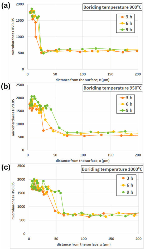
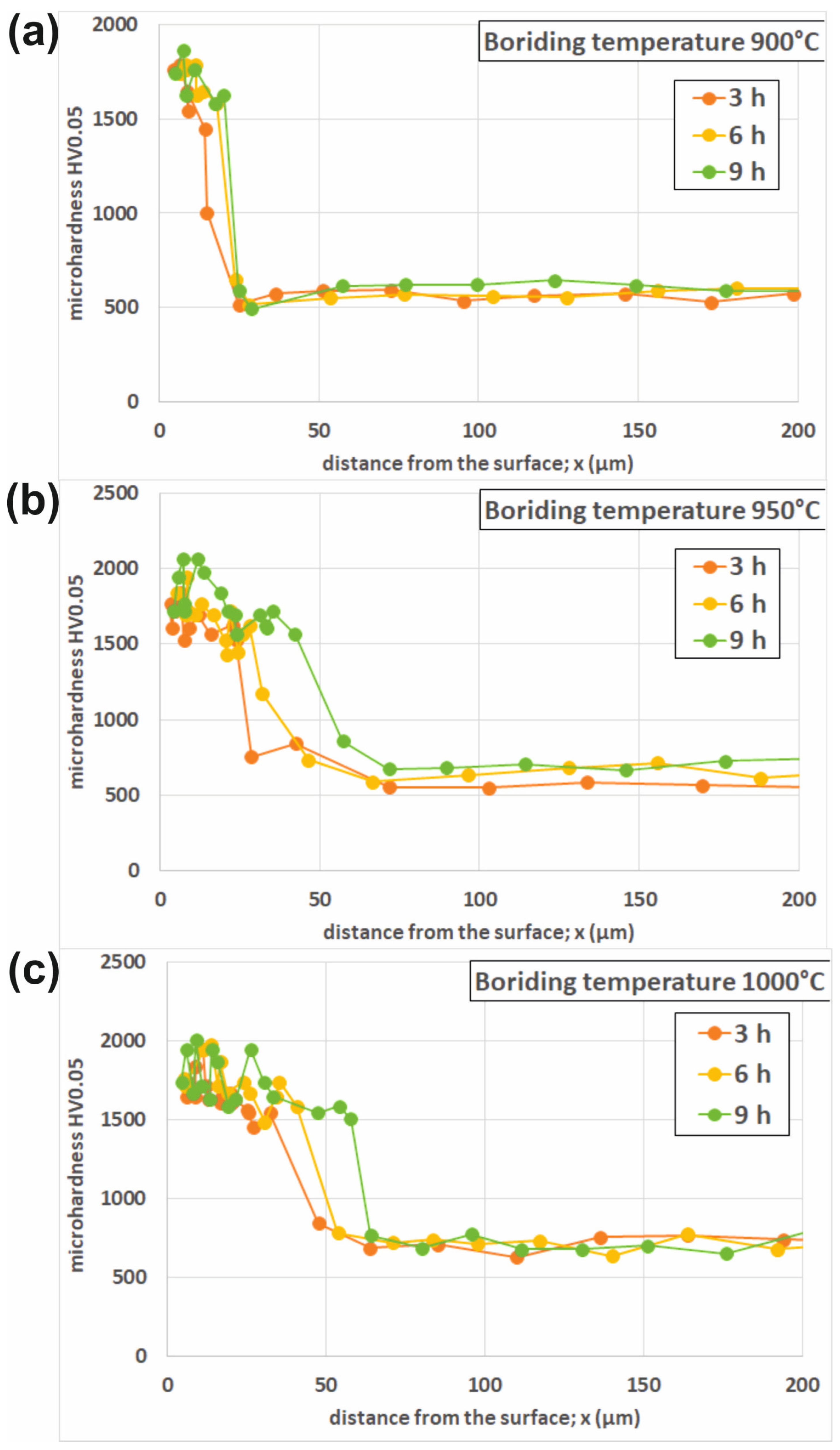
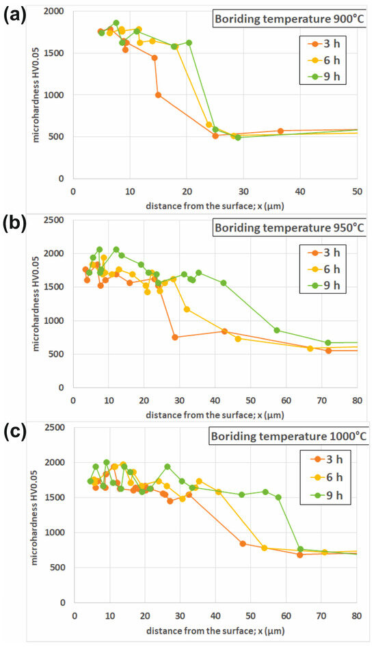
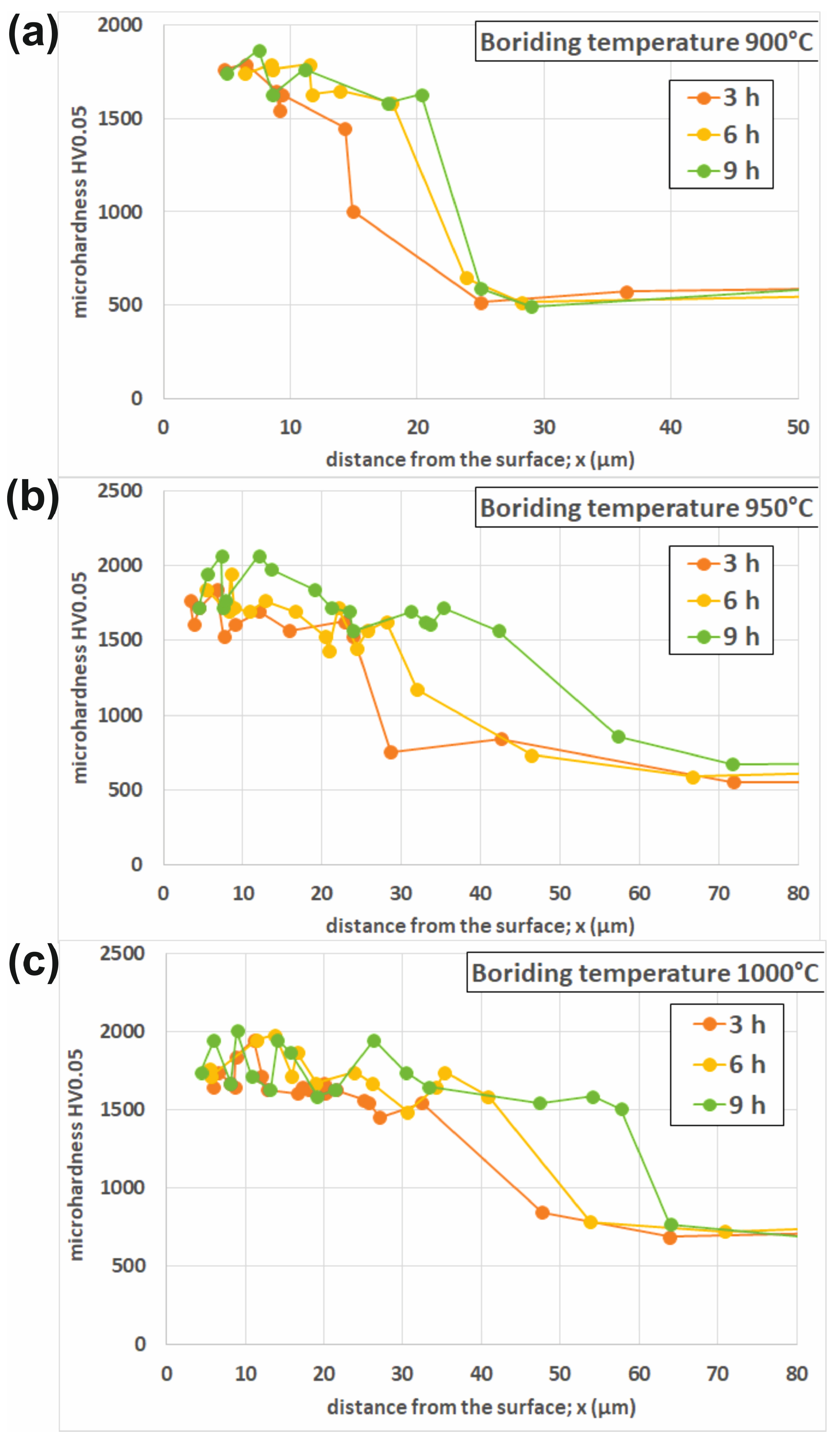
The full Vickers microhardness profiles versus the distance from the surface are presented in Figure 16, including both boride zones (FeB and Fe2B), the transition zone, and the substrate material. The microhardness was measured for K190 steel borided at 1173 K (Figure 16a), 1223 K (Figure 16b), and 1273 K (Figure 16c) for 3, 6, and 9 h. To more accurately show the hardness measured in the FeB and Fe2B boride zones, the profiles were limited to a distance slightly exceeding the total layer thickness (Figure 17). Obviously, the highest hardness in the range of 1739–2065 HV was measured in the FeB zone. The Fe2B zone was characterized by hardness values ranging from 1448 HV to 1716 HV. However, some differences were observed when comparing the profiles obtained at the same temperature for different durations of the process. In general, longer boriding durations were accompanied by an increase in the hardness measured in the FeB and Fe2B zones. This situation could have resulted from the higher degree of substitution of the iron atoms by chromium atoms in complex (Fe,Cr)B and (Fe,Cr)2B borides or simply the higher percentage of CrB and Cr2B chromium borides in the microstructure. In the same way, the increase in boriding temperature influenced the hardness measured. Böhler K190 steel represented a high-carbon tool steel. Simultaneously, the carbon content did not influence the hardness of the borided layer due to its insolubility in the iron borides [9]. Hence, the hardness of the borided layers produced on such steels depended mainly on the boriding parameters (temperature and time) as well as the presence of alloying elements in the substrate material. The transition region below the boride layer was characterized by a clearly lower hardness than that of the boride zones. (Figure 16). However, the presence of a high percentage of alloyed carbides with a high chromium and vanadium content resulted in increased hardness in this region when compared to that in the substrate material.
Figure 16.
Full microhardness profiles of powder-pack borided Böhler K190 steel at various temperatures: (a) 1173 K (900 °C), (b) 1223 K (950 °C), and (c) 1273 K (1000 °C).
Figure 17.
Microhardness profiles limited to boride zones of powder-pack borided Böhler K190 steel at various temperatures: (a) 1173 K (900 °C), (b) 1223 K (950 °C), and (c) 1273 K (1000 °C).
It is obvious that the borided layers are characterized by relatively high brittleness due to the formation of hard borides. This was not the subject of this study, but the issue is described in considerable detail in papers [2,6,7], in which fracture toughness was investigated. A very important factor influencing the properties of borided layers is the distribution of residual stresses. Heat treatment after boriding, as well as the lack thereof, is also important in this regard. Determining residual stresses in such layers using XRD is not easy due to the texture of the borides. Labor-intensive mechanical methods, such as the Davidenkov-Sachs method, provide the most reliable results. In general, the residual stresses on the surface after boriding should be compressive. The mismatch in the thermal expansion coefficients of the FeB and Fe2B borides also affects residual stress. The problem of this mismatch was addressed in paper [2], where the fracture toughness of borided layers was investigated.
4. Summary and Conclusions
The unique powder-pack boriding technique with an open retort using the Durborid®G powder mixture was used in order to produce borided layers on BÖHLER K190 MICROCLEAN® ledeburitic chromium steel manufactured with powder metallurgy. The boriding parameters were as follows: temperatures of 1173 K, 1223 K, and 1273 K and boriding times of 3 h, 6 h, and 9 h. The microstructure evolution, growth kinetics, and microhardness of the boride layers were studied. Based on the detailed analysis of the results presented, the following conclusions could be formulated:
- -
- The boriding parameters strongly influenced the thickness of the produced layers. The higher temperature and longer duration resulted in an increase in the thickness of the FeB zone and the complete FeB + Fe2B layer.
- -
- All the produced surface layers contained three zones: the outer FeB zone (1), with a predominant percentage of the FeB phase; the inner Fe2B zone (2), with a predominant percentage of Fe2B borides; and the transition zone (3), with an increased carbon concentration and a high percentage of chromium, vanadium, and iron carbides.
- -
- The high content of chromium in Böhler K190 steel was the reason for the additional presence of CrB and Cr2B borides in the borided layers, i.e., the FeB and Fe2B zones. It is also possible that complex borides (Fe,Cr)B or (Fe,Cr)2B occurred in the microstructure. In the future, possible Cr incorporation into the FeB/Fe2B phases could be confirmed by a Rietveld refinement of the XRD patterns.
- -
- The mean diffusion coefficient model was used to describe the growth kinetics of the FeB and FeB + Fe2B zones on the surface of powder-pack borided K190 steel and the evolution of the layer thicknesses. The calculated boron activation energies were comparable with other results for the powder-pack boriding of high-carbon tool steels.
- -
- The parameters of boriding (temperature and time) as well as the presence of alloying elements in the treated steel influenced the hardness of the borided layers. The higher boriding temperature and longer duration caused an increase in the hardness of the boride layers because of the higher percentage of hard chromium borides in the microstructure.
- -
- The obtained results showed that using the proposed technique, it is possible to produce borided layers on K190 steel, which have application potential, especially under conditions of high loads. Full confirmation of this thesis requires tests of resistance to frictional wear, which will be presented in the next paper.
Author Contributions
Conceptualization, N.M., M.K. (Michał Kulka), and M.K. (Mourad Keddam); Data Curation, N.M., M.K. (Michał Kulka), M.K. (Mourad Keddam), P.D., D.P.-P., and M.T.; Formal Analysis, M.K. (Michał Kulka) and M.K. (Mourad Keddam); Funding Acquisition, M.K. (Michał Kulka) and M.K. (Mourad Keddam); Investigation, N.M., M.K. (Michał Kulka), M.K. (Mourad Keddam), P.D., D.P.-P., and M.T.; Methodology, N.M., M.K. (Michał Kulka), M.K. (Mourad Keddam), P.D., D.P.-P., and M.T.; Project Administration, M.K. (Michał Kulka) and M.K. (Mourad Keddam); Resources, M.K. (Michał Kulka) and M.K. (Mourad Keddam); Supervision, M.K. (Michał Kulka) and M.K. (Mourad Keddam); Validation, N.M., M.K. (Michał Kulka), and M.K. (Mourad Keddam); Visualization, N.M., M.K. (Michał Kulka), M.K. (Mourad Keddam), P.D., D.P.-P., and M.T.; Writing—Original Draft, M.K. (Michał Kulka) and M.K. (Mourad Keddam); Writing—Review and Editing, M.K. (Michał Kulka). All authors have read and agreed to the published version of the manuscript.
Funding
This research was funded by the Ministry of Science and Higher Education in Poland—grant number 0513/SBAD/4850 and the Ministry of Higher Education and Scientific Research of Algeria—PRFU project, registered under reference number A11N01UN160420230012 and coordinated by the DGRSDT, Algeria.
Institutional Review Board Statement
Not applicable.
Informed Consent Statement
Not applicable.
Data Availability Statement
The authors confirm that the data supporting the findings of this study are available within the article.
Acknowledgments
The authors would like to thank their dear friend and co-worker, Natalia Makuch-Dziarska, who passed away prematurely, for her many years of creative contribution to the scientific development of the Institute of Materials Science and Engineering. The authors also wish to thank J. Jakubowski and Mikołaj Popławski from the Division of Metal Science and Surface Engineering for their help and cooperation during the realization of this work.
Conflicts of Interest
The authors declare no conflicts of interest. The funders had no role in the design of the study; in the collection, analyses, or interpretation of data; in the writing of the manuscript; or in the decision to publish the results.
Abbreviations
The following abbreviations are used in this manuscript:
| SEM | scanning electron microscope |
| EDS | energy dispersive spectrometer |
| XRD | X-ray diffraction |
| BSE | back-scattered electrons |
| PDCPPB | pulsed direct current powder-pack boriding |
References
- Kulka, M. Current Trends in Boriding: Techniques; Springer International Publishing: Cham, Switzerland, 2019. [Google Scholar]
- Kulka, M.; Makuch, N.; Piasecki, A. Nanomechanical characterization and fracture toughness of FeB and Fe2B iron borides produced by gas boriding of Armco iron. Surf. Coat. Technol. 2017, 325, 515–532. [Google Scholar] [CrossRef] [Scilit]
- Keddam, M.; Kulka, M.; Makuch, N.; Pertek, A.; Małdziński, L. A kinetic model for estimating the boron activation energies in the FeB and Fe2B layers during the gas-boriding of Armco iron: Effect of boride incubation times. Appl. Surf. Sci. 2014, 298, 155–163. [Google Scholar] [CrossRef] [Scilit]
- Keddam, M.; Chentouf, S.M. A diffusion model for describing the bilayer growth (FeB/Fe2B) during the iron powder-pack boriding. Appl. Surf. Sci. 2005, 252, 393–399. [Google Scholar] [CrossRef] [Scilit]
- Ozdemir, O.; Usta, M.; Bindal, C.; Ucisik, A.H. Hard iron boride (Fe2B) on 99.97 wt.% pure iron. Vacuum 2006, 80, 1391–1395. [Google Scholar] [CrossRef] [Scilit]
- Ucisik, A.H.; Bindal, C. Fracture toughness of boride formed on low-alloy steels. Surf. Coat. Technol. 1997, 94–95, 561–565. [Google Scholar] [CrossRef] [Scilit]
- Hernández-Sanchez, E.; Rodriguez-Castro, G.; Meneses-Amador, A.; Bravo-Bárcenas, D.; Arzate-Vazquez, I.; Martínez-Gutiérrez, H.; Romero-Romo, M.; Campos-Silva, I. Effect of the anisotropic growth on the fracture toughness measurements obtained in the Fe2B layer. Surf. Coat. Technol. 2013, 237, 292–298. [Google Scholar] [CrossRef] [Scilit]
- Campos-Silva, I.; Hernández-Sánchez, E.; Rodríguez-Castro, G.; Cimenoglu, H.; Nava-Sánchez, J.L.; Meneses-Amador, A.; Carrera-Espinoza, R. A study of indentation for mechanical characterization of the Fe2B layer. Surf. Coat. Technol. 2013, 232, 173–181. [Google Scholar] [CrossRef] [Scilit]
- Tsipas, D.N.; Rus, J. Boronizing of alloy steels. J. Mater. Sci. Lett. 1987, 6, 118–120. [Google Scholar] [CrossRef] [Scilit]
- Kulka, M.; Pertek, A.; Makuch, N. The importance of carbon concentration–depth profile beneath iron borides for low-cycle fatigue strength. Mater. Sci. Eng. A 2011, 528, 8641–8650. [Google Scholar] [CrossRef] [Scilit]
- Kulka, M.; Makuch, N.; Pertek, A.; Piasecki, A. An alternative method of gas boriding applied to the formation of borocarburized layer. Mater. Charact. 2012, 72, 59–67. [Google Scholar] [CrossRef] [Scilit]
- Taktak, S.; Tasgetiren, S. Identification of delamination failure of boride layer on common Cr-based steels. J. Mater. Eng. Perform. 2006, 15, 570–574. [Google Scholar] [CrossRef] [Scilit]
- Campos-Silva, I.; Martínez-Trinidad, J.; Doñu-Ruíz, M.A.; Rodríguez-Castro, G.; Hernández-Sánchez, E.; Bravo-Bárcenas, O. Interfacial indentation test of FeB/Fe2B coatings. Surf. Coat. Technol. 2011, 206, 1809–1815. [Google Scholar] [CrossRef] [Scilit]
- Herranz, G.; Matula, G.; Romero, A. Effects of chromium carbide on the microstructures and wear resistance of high speed steel obtained by powder injection moulding route. Powder Metall. 2017, 60, 120–130. [Google Scholar] [CrossRef] [Scilit]
- Campos-Silva, I.; Ortiz-Domínguez, M.; Tapia-Quintero, C.; Rodríguez-Castro, G.; Jiménez-Reyes, M.Y.; Chávez-Gutiérrez, E. Kinetics and boron diffusion in the FeB/Fe2B layers formed at the surface of borided high-alloy steel. J. Mater. Eng. Perform. 2012, 21, 1714–1723. [Google Scholar] [CrossRef] [Scilit]
- Dybkov, V.I. Growth of boride layers on the 13% Cr steel surface in a mixture of amorphous boron and KBF4. J. Mater. Sci. 2007, 42, 6614–6627. [Google Scholar] [CrossRef] [Scilit]
- Badini, C.; Gianoglio, C.; Pradelli, G. Preferential distribution of chromium and nickel in the borided layer obtained on synthetic Fe-Cr-Ni alloys. J. Mater. Sci. 1986, 21, 1721–1729. [Google Scholar] [CrossRef] [Scilit]
- Carbucicchio, M.; Palombarini, G. Effects of alloying elements on the growth of iron boride coatings. J. Mater. Sci. Lett. 1987, 6, 1147–1149. [Google Scholar] [CrossRef] [Scilit]
- Dybkov, V.I.; Goncharuk, L.V.; Khoruzha, V.G.; Samelyuk, A.V.; Sidorko, V.R. Growth kinetics and abrasive wear resistance of boride layers on Fe–15Cr alloy. Mater. Sci. Technol. 2011, 27, 1502–1512. [Google Scholar] [CrossRef] [Scilit]
- Taktak, S. Some mechanical properties of borided AISI H13 and 304 steels. Mater. Des. 2007, 28, 1836–1843. [Google Scholar] [CrossRef] [Scilit]
- Campos, I.; Farah, M.; Lopez, N.; Bermudez, G.; Rodriguez, G.; Villa Velazquez, C. Evaluation of the tool life and fracture toughness of cutting tools boronized by the paste boriding process. Appl. Surf. Sci. 2008, 254, 2967–2974. [Google Scholar] [CrossRef] [Scilit]
- Bartkowska, A.; Swadźba, R.; Popławski, M.; Bartkowski, D. Microstructure, microhardness, phase analysis and chemical composition of laser remelted FeB-Fe2B surface layers produced on Vanadis-6 steel. Opt. Laser Technol. 2016, 86, 115–125. [Google Scholar] [CrossRef] [Scilit]
- Orihel, P.; Jurči, P.; Keddam, M. Characterizations and Kinetic Modelling of Boride Layers on Bohler K190 Steel. Coatings 2023, 13, 1000. [Google Scholar] [CrossRef] [Scilit]
- Hudáková, M.; Kusý, M.; Sedlická, V.; Grgać, P. Analysis of the boronized layer on K190 PM tool steel. Mater. Tehnol. 2007, 41, 81–84. [Google Scholar]
- Böhler. Available online: https://www.bohler-edelstahl.com/app/uploads/sites/248/productdb/api/k190-microclean_en_gb.pdf (accessed on 12 April 2026).
- Campos-Silva, I.; Ortiz-Domínguez, M.; Keddam, M.; López-Perrusquia, N.; Carmona-Vargas, A.; Elías-Espinosa, M. Kinetics of the formation of Fe2B layers in gray cast iron: Effects of boron concentration and boride incubation time. Appl. Surf. Sci. 2009, 255, 9290–9295. [Google Scholar] [CrossRef] [Scilit]
- Młynarczak, A. Modification of Structure and Properties of Single- and Multicomponent Diffusion Layers of Chromium, Vanadium and Titanium Carbides Produced on Steels by Powder-Pack Method; Dissertation No. 396; Publishing House of Poznan University of Technology: Poznan, Poland, 2005; ISBN 83-7143-336-0. (In Polish) [Google Scholar]
- Wei, X.; Chen, Z.; Zhong, J.; Wang, L.; Yang, W.; Wang, Y. Effect of alloying elements on mechanical, electronic and magnetic properties of Fe2B by first-principles investigations. Comput. Mater. Sci. 2018, 147, 322–330. [Google Scholar] [CrossRef] [Scilit]
- Makuch, M.; Kulka, M.; Keddam, M.; Piasecki, A. Growth Kinetics, Microstructure Evolution, and Some Mechanical Properties of Boride Layers Produced on X165CrV12 Tool Steel. Materials 2023, 16, 26. [Google Scholar] [CrossRef] [Scilit]
- Keddam, M.; Kulka, M. Simulation of Boriding Kinetics of AISI D2 Steel using Two Different Approaches. Met. Sci. Heat Treat. 2020, 61, 756–763. [Google Scholar] [CrossRef] [Scilit]
- Nait Abdellah, Z.; Boumaali, B.; Keddam, M. Experimental evaluation and modelling of the boronizing kinetics of AISI H13 hot work tool steel. Mater. Test. 2021, 63, 1136–1141. [Google Scholar] [CrossRef] [Scilit]
- Yu, L.G.; Chen, X.J.; Khor, K.A.; Sundararajan, G. FeB/Fe2B Phase Transformation During SPS Pack-Boriding: Boride Layer Growth Kinetics. Acta Mater. 2005, 53, 2361–2368. [Google Scholar] [CrossRef] [Scilit]
- Okamoto, H. B-Fe (Boron-Iron). J. Phase Equilibria Diffus. 2004, 25, 297–298. [Google Scholar] [CrossRef] [Scilit]
- Keddam, M.; Chegroune, R.; Kulka, M.; Panfil, D.; Ulker, S.; Taktak, S. Characterization and Diffusion Kinetics of the Plasma Paste Borided AISI 440C Steel. Trans. Indian Inst. Met. 2017, 70, 1377–1385. [Google Scholar] [CrossRef] [Scilit]
- Sista, V.; Kahvecioglu, O.; Eryilmaz, O.L.; Erdemir, A.; Timur, S. Electrochemical boriding and characterization of AISI D2 tool steel. Thin Solid Film. 2011, 520, 1582–1588. [Google Scholar] [CrossRef] [Scilit]
- Rosales-Lopez, J.L.; Olivares-Luna, M.; Castillo-Vela, L.E.; Chaparro-Pérez, K.D.; Campos-Silva, I. Unprecedented results on the high current density-low temperature boriding of hot work tool steels. Surf. Coat. Technol. 2025, 516, 132726. [Google Scholar] [CrossRef] [Scilit]
- Ayvaz, S.İ.; Aydın, İ.; Bahcepınar, A.İ. Effect of Shot Blasting on the Boriding Kinetics of AISI 316L Stainless Steel. Prot. Met. Phys. Chem. Surf. 2023, 59, 671–678. [Google Scholar] [CrossRef] [Scilit]
- Aydogmus, T.; Çicek, B.; Topuz, P.; Aydin, Ö. Growth kinetics of Fe2B layer formed on the surface of borided AISI M2 high-speed steel. Mater. Test. 2024, 66, 1720–1727. [Google Scholar] [CrossRef] [Scilit]

Disclaimer/Publisher’s Note: The statements, opinions and data contained in all publications are solely those of the individual author(s) and contributor(s) and not of MDPI and/or the editor(s). MDPI and/or the editor(s) disclaim responsibility for any injury to people or property resulting from any ideas, methods, instructions or products referred to in the content. |
© 2026 by the authors. Licensee MDPI, Basel, Switzerland. This article is an open access article distributed under the terms and conditions of the Creative Commons Attribution (CC BY) license.