


Highlights
What are the main findings?
- The addition of cBN transforms the alloy’s phase structure from FCC to BCC main phase, reducing lattice constants and cell volumes.
- cBN eliminates pore defects and reduces element segregation from 21.39% to below 13%.
- 1.0 wt.% cBN content yields the lowest friction coefficient and highest wear resistance, along with optimal corrosion resistance.
What are the implications of the main findings?
- cBN-reinforced HEACs offer a promising solution for enhancing the surface properties of 45 steel, extending its service life in harsh environments.
- The ability to tailor phase composition and microstructure through cBN addition opens new avenues for designing high-performance coatings.
- The improved wear and corrosion resistance of cBN-reinforced HEACs can lead to reduced maintenance costs and enhanced reliability in mechanical components.
Abstract
Although 45 steel is widely used in the manufacture of mechanical parts, its application in harsh working conditions is limited owing to its low hardness, poor wear resistance, and corrosion resistance. Laser cladding can enhance the performance of the working surface without sacrificing substrate toughness. CoCuNiTi HEACs with different cBN additions were successfully prepared on a 45-steel substrate. The phase structure, microstructure, elemental composition, wear, and corrosion behavior of CoCuNiTi + x cBN (x = 0.0, 0.5, and 1.0 wt.%) HEACs were investigated using XRD, OM, SEM, EDS, friction and wear tester, and electrochemical workstation, respectively. The results show that all three coatings exhibit a dual-phase structure composed of FCC and BCC phases. The addition of cBN transforms the alloy phase structure from the original FCC main phase to the BCC main phase. The incorporation of cBN significantly reduces the lattice constant and cell volume of the alloy phase. The change in the alloy phase density is negatively correlated with the cell volume. CoCuNiTi + x cBN (x = 0.0, 0.5, and 1.0 wt.%) alloys have a dendritic structure. No pores were observed in the cBN-containing sample. The content of Ti in the primary phase is the highest. Co is enriched in the dendrite region, and Cu is enriched in the interdendrite region. The significant reduction in the average segregation coefficient for cBN-containing samples is attributed to the heterogeneous nucleation of the alloy melt at lower undercooling levels and the significant increase in the diffusion rate. The friction coefficient of the alloy decreases significantly with increasing cBN content. The sample with 1.0 wt.% cBN shows the best wear resistance, mainly due to the combined effects of hard particle support, solid solution strengthening, phase interface reduction, and high thermal conductivity of cBN. The sample with 1.0 wt.% cBN has the largest capacitive arc radius and charge-transfer resistance, along with the lowest annual corrosion rate, indicating optimal corrosion resistance. This is primarily related to the reduction in pore defects caused by cBN addition, hindrance of uniform penetration of the corrosive medium by dispersed cBN particles, and increased complexity of the anodic dissolution process. CoCuNiTi HEACs reinforced by cBN can simultaneously improve the wear and corrosion resistance of the surface of the 45-steel substrate, providing a feasible strategy for the design of high-performance protective coatings.
1. Introduction
The 45 steel is widely used in the manufacturing of mechanical components such as gears, drive shafts, connecting rods, and molds owing to its excellent mechanical properties, machinability, and low cost [1,2]. It occupies an important position in fields including mechanical manufacturing, rail transit, aerospace, and energy equipment, earning recognition as the “industrial backbone” in the industrial structural steel sector [3,4]. With the rapid development of industrial technology, the application of 45 steel in high-speed, heavy-load, and harsh working conditions is limited owing to its low hardness and poor wear/corrosion resistance [5,6,7]. Consequently, while maintaining the good toughness of the 45-steel core, it is crucial to significantly enhance the strength, wear resistance, and corrosion resistance of the working surface. This has become an important research direction for performance redesign and optimization [8,9,10]. Laser cladding has become a common surface modification technology for preparing metal coatings owing to its high processing efficiency, rapid cooling rates, small heat-affected zones, low dilution ratios, easy addition of strengthening phases, and high coating-substrate bond strength [11,12].
In recent years, superhard material-reinforced high-entropy alloy coatings (HEACs) have become a research hotspot in the field of surface engineering [13,14,15]. Diamond and cubic boron nitride (cBN) are common superhard materials. Diamond is the hardest known material and is often used as a reinforcing phase in various high-entropy alloy coatings. Wang et al. [15] successfully fabricated diamond-reinforced FeCoCrNi-Mo composite coatings by high-speed laser cladding. The addition of diamonds significantly improved the wear resistance of the coating; however, microcracks appeared. Under high laser power and low scanning speed, the diamond was graphitized and lost its crystalline morphology, while diffused C formed carbides with Cr/Mo. The optimal wear resistance was achieved at a diamond content of 15 wt.%. Zhang et al. [16] prepared (FeNiCoCrTi0.5)Cx (x = 3, 6, 12 wt.%) composite coatings with varying diamond contents on a 45-steel substrate by laser cladding. The diamond-containing coatings exhibited good metallurgical bonding with the substrate, and no pore defects were observed in the microstructure. The addition of diamond leads to the instability of the BCC phase and the formation of carbides. When the addition of diamond is 12 wt.%, the hardness of the coating is four times that of the substrate. Diamonds have poor thermal stability. During cladding, diamonds are prone to graphitization, the generation of harmful carbides, and a reduction in interfacial bonding strength due to diffusion between the diamond and metal substrate [17,18]. The hardness of cBN is only lower than that of diamonds, yet its thermal stability far exceeds that of diamonds [19]. It is also commonly used as a superhard phase to reinforce the high-entropy alloy coatings. Yu et al. [20] employed laser cladding to fabricate cBN-reinforced (CoCrNi)94Al3Ti3 composite coatings. After the addition of cBN, the alloy phase transformed from the original single FCC phase to the FCC and BCC dual-phase structure, simultaneously generating micro-nano structures of TiN, CoCr, and CrB. High-energy lasers can convert some cBN into hexagonal boron nitride (hBN), which has better lubrication properties. The hardness of the cBN-containing coating increased by 2.2 times, its wear resistance improved by 5.6 times, and its friction coefficient decreased by 18.97%. Wang et al. [21] employed laser cladding and particle reinforcement techniques to prepare (NiCoCr)94Al3Ti3 coatings with cBN and cBN-hBN co-addition on titanium alloy surfaces. The hardness of the dual-phase co-added alloy increases significantly from 149.8 HV0.5 for the single-phase added alloy to 1083.8 HV0.5, and its wear rate is 1.37 times that of the single-phase added alloy. cBN-containing alloys primarily rely on their inherent hardness to resist wear and enhance wear resistance. In contrast, the addition of cBN and hBN to the alloy not only enhances its wear resistance but also facilitates the formation of a lubricating film to further improve its wear resistance.
CoCuNiTi is a typical high-entropy alloy with a dual-phase structure composed of face-centered cubic (FCC) and body-centered cubic (BCC) phases [22]. Research on these alloys mainly focuses on component addition, element substitution, and rare earth oxide doping [23,24,25]. Okumuş et al. [23] prepared Al-added AlCoCuNiTi high-entropy alloys via high-energy ball milling and sintering. After 80–120 h of ball milling, a dual-phase solid solution composed of BCC and FCC structures and intermetallic compounds was formed. The grain size of the sample decreased to 5.67 nm, and the dislocation density increased to 31.14 × 10¹⁵/m2 after increasing the proportion of Ti and milling for 120 h. After 120 h of ball milling and sintering at 815 °C, the hardness of the 8% Ti-doped sample can reach 882 ± 20 HV1, and its mechanical properties are improved. Li et al. [24] prepared CoCrNiTi alloy films composed of FCC and amorphous phases by substituting Cr for Cu using direct current (DC) magnetron sputtering. With an increase in the Ti content, the degree of atomic mismatch in the alloy increases, promoting a higher amorphous phase content. The hardness, toughness, and adhesion strength of the films increase first and then decrease with increasing Ti content. At a Ti addition of 12.5 at. %, the alloy exhibits maximum hardness (13.25 GPa), toughness, and bond strength (28.5 N), along with the lowest wear rate (0.56 × 10⁻⁴ mm3·N−1·m−1). When the Ti content is 23.4 at. %, the film has the best corrosion resistance. Ma et al. [25] prepared CeO2-doped CoCuNiTi HEACs on the surface of a 45-steel substrate by laser cladding. The 1 wt.% CeO2 doping transformed the alloy phase from FCC main phase and BCC phase to BCC main phase and FCC phase. After adding CeO2, the primary dendrite (DR) spacing is reduced from 8.10 μm to 6.51 μm. The sample containing 1.0 wt.% CeO2 has the lowest corrosion current density, largest capacitive arc radius and charge-transfer resistance, and highest polarization resistance in 3.5 wt.% NaCl solution, demonstrating optimal corrosion resistance under these conditions.
Currently, there are few reports on cBN-reinforced CoCuNiTi high-entropy alloy coatings. In this paper, CoCuNiTi + x cBN (x = 0.0, 0.5, and 1.0 wt.%) laser cladding layers were successfully prepared on the surface of 45 steel. This study thoroughly examined the influence of varying cBN content on the phase composition, microstructure, composition distribution, and wear/corrosion behavior of these coatings. The aim of this study is to elucidate the strengthening and protective mechanisms of cBN-reinforced high-entropy alloy coatings, thereby providing a reference for the development and design of high-performance coatings for 45 steels. Although cBN and high-entropy alloys are relatively expensive, their application as thin coatings on a conventional 45 steel substrate via laser cladding provides a cost-effective solution for extreme wear environments. This approach leverages the substrate’s toughness and low cost while delivering exceptional surface properties, significantly extending the component service life and reducing the overall lifecycle costs.
2. Materials and Methods
CoCuNiTi + x cBN (x = 0.0, 0.5, and 1.0 wt.%) HEACs with different cBN additions were prepared by laser cladding. cBN was incorporated at a concentration of 0.5 wt.% and 1.0 wt.%, primarily for the following reasons: (1) Hard-particle reinforcement mechanism. The hardness of cBN is second only to that of diamond [19]. As a hard phase, cBN is uniformly dispersed in the alloy coating, which can bear the main load during the friction process and significantly improves the wear resistance of the coating. (2) Heterogeneous nucleation and microstructural optimization. The melting point of cBN is as high as approximately 3207 °C [26], far exceeding that of the metal substrate. When cBN particles are added to the high-entropy alloy melt, they serve as substrates for heterogeneous nucleation, reducing the nucleation undercooling and promoting the solid-phase precipitation of the alloy at higher temperatures, thereby allowing sufficient element diffusion. This directly leads to a reduction in the lattice constants and cell volumes, a decrease in element segregation, and the elimination of pore defects, thereby optimizing the microstructure of the coating. (3) Aggregation and crack risks due to excessive addition. An increase in the cBN content reduces the distance between the particles, significantly enhancing the agglomeration effect driven by the surface energy. Agglomerated cBN particles not only fail to provide effective reinforcement but also become stress concentration sources. Owing to mismatched thermophysical properties, they are prone to inducing microcracks during cooling processes [27,28]. (4) Toughness-brittleness balance. When a large amount of cBN is added, hard phases such as TiN and CrB are easily formed [20]. When added in appropriate amounts, these in situ-generated reinforcing phases can increase the coating hardness without significantly sacrificing toughness. However, excessive addition leads to the excessive formation of brittle phases, reducing the toughness of the coating and significantly increasing its brittleness, thereby diminishing its anti-stripping ability. (5) Cost-effectiveness optimization. While ensuring a significant improvement in performance, selecting the minimum effective dosage is key to achieving the best cost-effectiveness for engineering applications. Although further increasing the addition amount may further improve the performance slightly, the material cost increases significantly, and the risk of agglomeration and crack increases, which does not conform to the engineering principle of “achieving key performance improvements at a reasonable cost.”
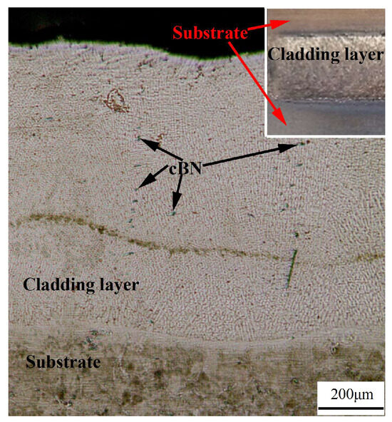
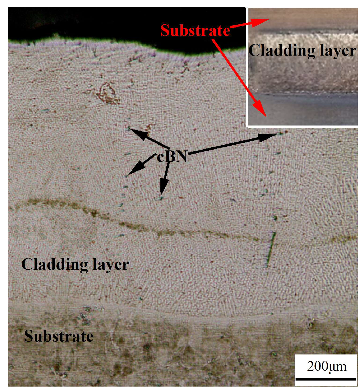
The required pure metal powders Co (purity 99.5%, particle size 200 mesh, Shanghai Guanjin Powder Materials Co., Ltd., Shanghai, China), Cu (purity 99.9%, particle size 200 mesh, Shanghai Guanjin Powder Materials Co., Ltd., Shanghai, China), Ni (purity 99.9%, particle size 200 mesh, Shanghai Guanjin Powder Materials Co., Ltd., Shanghai, China), and Ti (purity 99.6%, particle size 200 mesh, Baoji Hengchuang Metal Products Co., Ltd., Baoji, China) were weighed according to an equal atomic ratio. An appropriate amount of cBN (purity 99.0%, particle size 80 mesh, Funik Ultrahard Material Co., Ltd., Zhengzhou, China) particles were weighed according to the mass percentage. The weighed raw materials were placed in an agate mortar and ground for 30 min. The selected 45 steel substrates underwent quenching and tempering treatments prior to laser cladding. The quenching and tempering processes were as follows: first, the substrates were heated to 840 °C and held for 30 min, then oil-quenched; next, they were heated to 580 °C and held for 60 min, followed by air cooling to room temperature; finally, they were cut into 150 mm × 80 mm × 10 mm blocks. The surface of the 45-steel substrates (Zhengzhou Feihong Heat Treatment EquipmentManufacturing Co., Ltd., Zhengzhou, China) was polished and derusted using SiC sandpaper (Shanghai Xinshang Sand Abrasives Co., Ltd., Shanghai, China), cleaned with alcohol, and dried. Next, the above-mentioned raw materials were mixed with a binder (liquid sodium silicate) and prefabricated on the surface of the 45-steel substrates using the single-layer and single-strip methods, with a thickness of about 1 mm. In this process, the prefabricated layer should be kept as flat as possible to avoid many bubbles and voids. The prefabricated samples were kept at 100 °C for 30 min in a 202-00 AB electrothermal constant-temperature drying oven (Hangzhou Chuanyi Experimental Instrument Co., Ltd., Hangzhou, China), and laser cladding was performed using an FL-DLight3-4000 laser (Focuslight Technologies Inc., Xi’an, China). The cladding parameters were as follows: power, 3 kW; speed, 5 mm/s; and spot diameter, 6 mm. The working distance between the laser head and coating surface was 30 cm. High-purity argon was used as shielding gas throughout the process, with a pressure of 1.1 GPa and a flow rate of 15 L/min. After the cladding samples cooled to room temperature, they were cut into 10 mm × 10 mm × 5 mm metal blocks using a DK-M140 wire-cutting machine (Hangzhou Tiangong Machine Tool Manufacturing Co., Ltd., Hangzhou, China). The metal block was polished after grinding with metallographic sandpaper to remove scratches. It was etched with aqua regia for approximately 3 s, then immediately rinsed with alcohol and dried with a hair dryer. Figure 1 shows a metallographic photograph of the cross-section of the sample, and the illustration shows a physical photograph of the cladding layer.
Figure 1.
Metallographic photograph of the cross-section of the HEAC sample; the illustration is a physical photograph of the cladding layer.
The phase composition of CoCuNiTi + x cBN (x = 0.0, 0.5, and 1.0 wt.%) HEACs was characterized using an Ultima IV X-ray diffractometer (XRD, Rigaku Corporation, Tokyo, Japan). The test voltage and current were 40 kV and 20 mA, respectively. The microstructure of the cross sections of the samples was observed using a DMM-150C optical microscope (OM, Carl Zeiss Management Co., Ltd., Oberkochen, Germany). The microstructure of the coating surface was examined using a PHENOM PROX scanning electron microscope (SEM, Funa scientific instruments Co., Eindhoven, The Netherlands). The distribution of alloying elements in different regions of the coating was characterized using Aztec X-Max 90 energy-dispersive spectrometry (EDS, Oxford Instruments, Oxford, UK). The friction coefficients of the samples were tested using an MFT-R4000 reciprocating friction and wear tester (Lanzhou Huahui Instrument Technology Co., Ltd., Lanzhou, China). The load of the wear test was 10 N, the reciprocating frequency was 5 Hz, the rotation radius was 2 mm, and the duration was 15 min. The corrosion behavior was evaluated using a three-electrode system on a CHI 760E electrochemical workstation (Shanghai Chenhua Science Technology Corp., Shanghai, China). The samples were first immersed in the corrosion solution for approximately 20 min to ensure the stabilization of the open-circuit potential before testing. Polarization curves were scanned at 2 mV/s, with the impedance spectroscopy amplitude set to 5 mV. Circuit fitting employed the R(QR) model in the ZSimDemo 3.30d software. All the above tests were conducted at room temperature.
3. Results and Discussion
3.1. Phase Composition
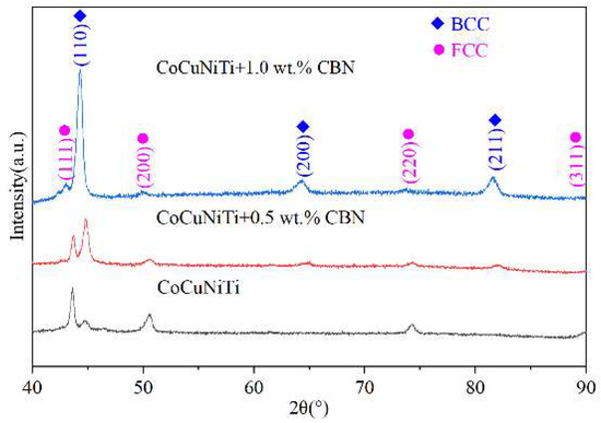
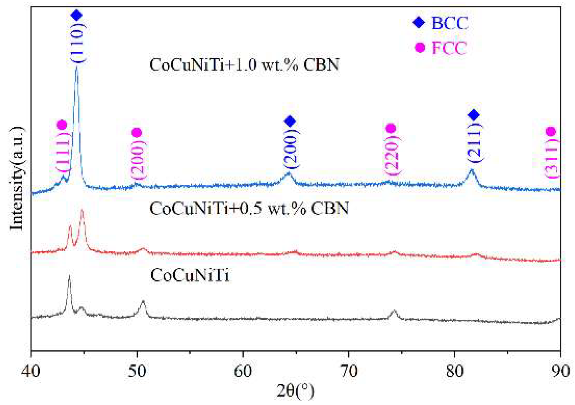
Figure 2 shows the X-ray diffraction patterns of CoCuNiTi + x cBN (x = 0.0, 0.5, and 1.0 wt.%) HEACs before and after cBN addition. By comparing with the standard powder diffraction cards from the Joint Committee on Powder Diffraction Standards (JCPDS), the shapes of the diffraction peaks marked as FCC and BCC in the three alloys are basically consistent with Ni (JCPDS No. 65-2865) and Ti (JCPDS No. 65-5970), respectively. Based on the strongest peaks of Ni (44.493°) and Ti (38.415°) in the standard card, the FCC phase in CoCuNiTi + x cBN (x = 0.0, 0.5, and 1.0 wt.%) shifted 0.840°, 0.786° and 0.199° to smaller angles, respectively, and the BCC phase shifted 6.423°, 6.375° and 5.873° to larger angles, respectively. According to the Bragg equation [29],
where d represents the interplanar spacing, θ is the diffraction angle, n indicates the diffraction order, and λ is the Kα-ray wavelength of the Cu target (1.54056 Å). Table 1 lists the characteristic parameters of each element in the CoCuNiTi + x cBN (x = 0.0, 0.5, and 1.0 wt.%) alloys. As shown in Table 1, among the metal elements, Ni (0.125 nm) has the smallest atomic radius, whereas Ti (0.146 nm) has the largest. When other metal elements occupy the lattice sites of Ni in the FCC structure, it inevitably leads to cell expansion and an increase in the interplanar spacing d. From Equation (1), the diffraction angle shifts towards a smaller angle. Conversely, when other metal elements occupy the lattice sites of Ti in the BCC structure, they inevitably cause cell shrinkage and a decrease in the interplanar spacing d. Consequently, the diffraction angle shifts towards a larger angle.
Figure 2.
XRD patterns of CoCuNiTi + x cBN (x = 0.0, 0.5, and 1.0 wt.%) HEACs with different cBN additions.
Table 1.
Characteristic parameters of elements in CoCuNiTi + x cBN (x = 0.0, 0.5, and 1.0 wt.%) alloys.
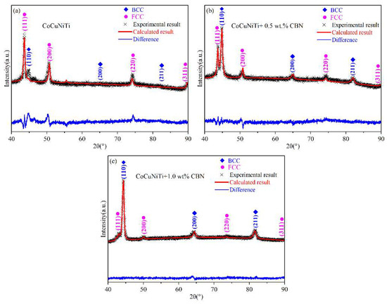
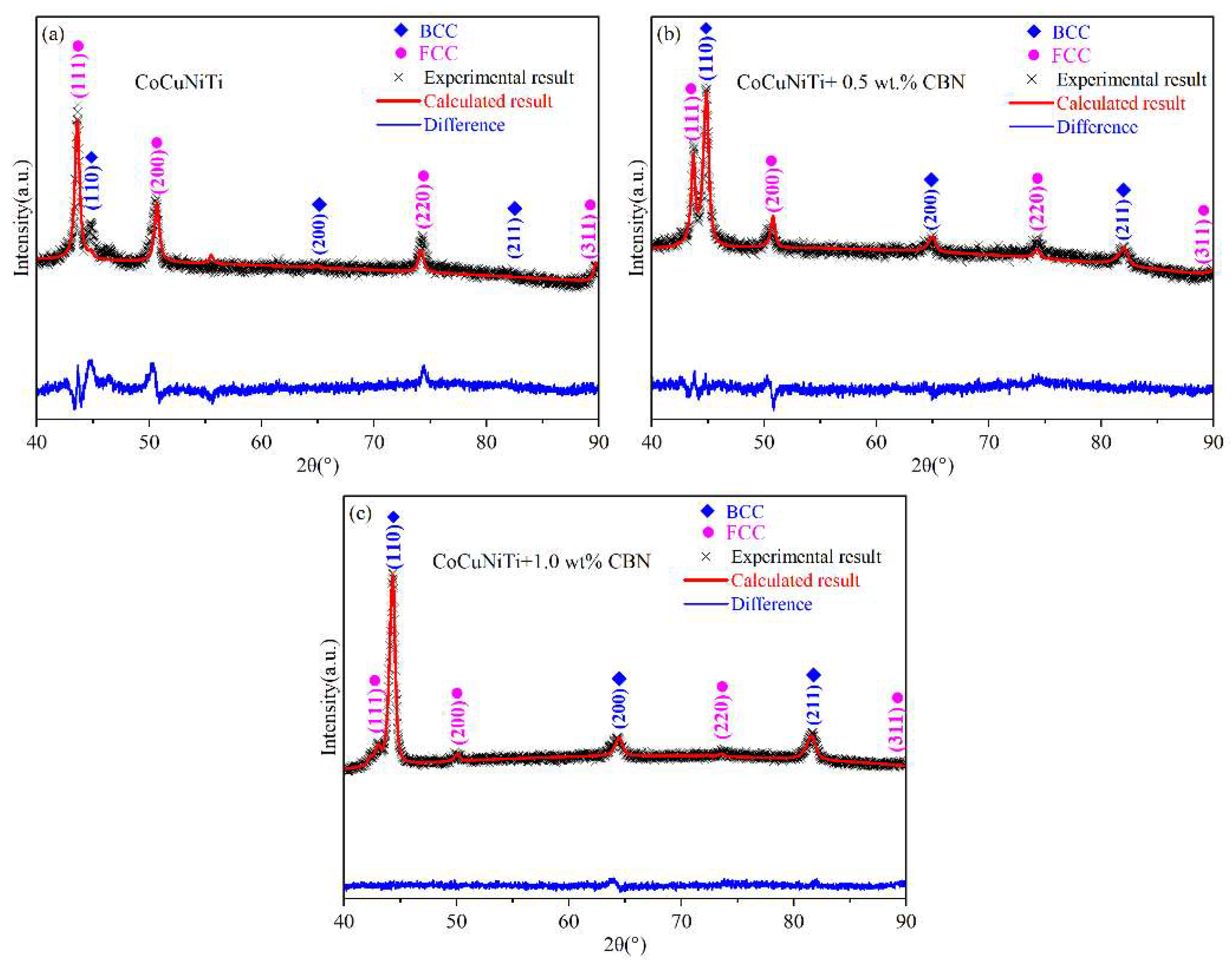
To better analyze the effect of cBN addition on the phase composition of CoCuNiTi + x cBN (x = 0.0, 0.5, and 1.0 wt.%), the whole pattern fitting and Rietveld refinement (WPFRR) were performed on the X-ray diffraction data in Figure 2. The fitting weight factors (R) were 6.82%, 2.86%, and 1.42%, respectively. The fitting results are presented in Figure 3 and Table 2. As shown in Figure 3 and Table 2, all three alloys exhibit a dual-phase structure composed of BCC and FCC. The two alloys with cBN addition transformed from the original FCC main phase to the BCC main phase after the cBN addition. As the cBN content increases, the proportion of the BCC phase gradually rises. Compared with the CoCuNiTi alloy, the lattice constants of the FCC and BCC phases in CoCuNiTi + 0.5 wt.% cBN alloy were significantly reduced by 12.23% to 13.15%, and cell volumes were reduced by 32.40% to 34.50%. This is because cBN has a high melting point (approximately 3207 °C) [26], and cBN particles can be used as substrates for heterogeneous nucleation in the alloy melt. This helps reduce the degree of undercooling required for solidification and nucleation resistance. The reduction in the required undercooling allows substantial solid-phase precipitation at higher temperatures, facilitating rapid alloying element diffusion and significantly decreasing lattice distortion. This leads to a decrease in the lattice constant and cell volume. When the addition of cBN further increased to 1.0 wt.%, the lattice constant and cell volume of the alloy slightly increased. This is because more B and N elements enter and occupy the interstitial positions of the two-phase lattice structure through solid-state diffusion, resulting in cell expansion. Compared with CoCuNiTi alloys, the density of cBN-containing alloys increased significantly, ranging from 32.42% to 34.47%, exhibiting a negative correlation with the cell volume reduction, which ranged from 32.40% to 34.50%. This is because a small increase in mass (≤1.00%) is negligible in the case of a significant decrease in the cell volume.
Figure 3.
WPFRR patterns of CoCuNiTi + x cBN (x = 0.0, 0.5, and 1.0 wt.%) HEACs with different cBN additions. (a) x = 0.0 wt.%; (b) x = 0.5 wt.%; (c) x = 1.0 wt.%.
Table 2.
WPFRR results for CoCuNiTi + x cBN (x = 0.0, 0.5, and 1.0 wt.%) HEACs.
To further validate the stability of the dual-phase structure composed of FCC and BCC in CoCuNiTi + x cBN (x = 0.0, 0.5, and 1.0 wt.%) alloys, Gibbs free energy (ΔGmix), atomic radius difference (δ), and valence electron theory (VEC) were calculated using the following equations [32,33,34],
where ΔHmix is the enthalpy of mixing (kJ/mol), T is the thermodynamic temperature (K), ΔSmix is the entropy of mixing (J·K−1·mol−1), R is the gas constant (8.314 J·mol−1·K−1), N is the number of alloy constituents, ci is the atomic percentage of constituent i, is the enthalpy of mixing between components i and j (kJ/mol), ri is the atomic radius of component i (nm), is the average atomic radius of the alloy elements (nm), and (VEC)i is the VEC of the ith element. Table 3 presents the enthalpy of mixing between any two elements in CoCuNiTi + x cBN (x = 0.0, 0.5, and 1.0 wt.%) alloys, with values sourced from literature [35]. The atomic radius differences between any two elements were calculated using Equations (5) and (6). The enthalpy of mixing, entropy of mixing, Gibbs free energy, atomic radius difference, and VEC of CoCuNiTi + x cBN (x = 0.0, 0.5, and 1.0 wt.%) alloys can be calculated using Equations (2)–(8). The calculation results are presented in Table 4. As shown in Table 4, with increasing cBN content, the entropy of mixing of the alloy gradually increases, whereas the enthalpy of mixing and Gibbs free energy progressively decrease, indicating enhanced stability of the alloy. According to the VEC phase formation theory [36], a higher VEC value indicates greater stability of the FCC phase, whereas a lower VEC value favors the BCC phase. As the cBN content increases, the VEC value gradually decreases, favoring an increase in the BCC phase content. This finding is consistent with the results of previous X-ray analyses.
Table 3.
Atomic radius differences and enthalpy of mixing between alloying elements in CoCuNiTi + x cBN (x = 0.0, 0.5, and 1.0 wt.%) HEACs.
Table 4.
Thermodynamic Parameters of CoCuNiTi + x cBN (x = 0.0, 0.5, and 1.0 wt.%) HEACs.
3.2. Microstructure
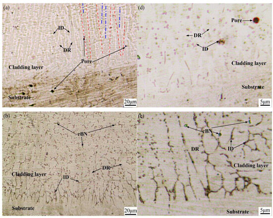
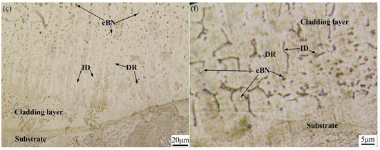
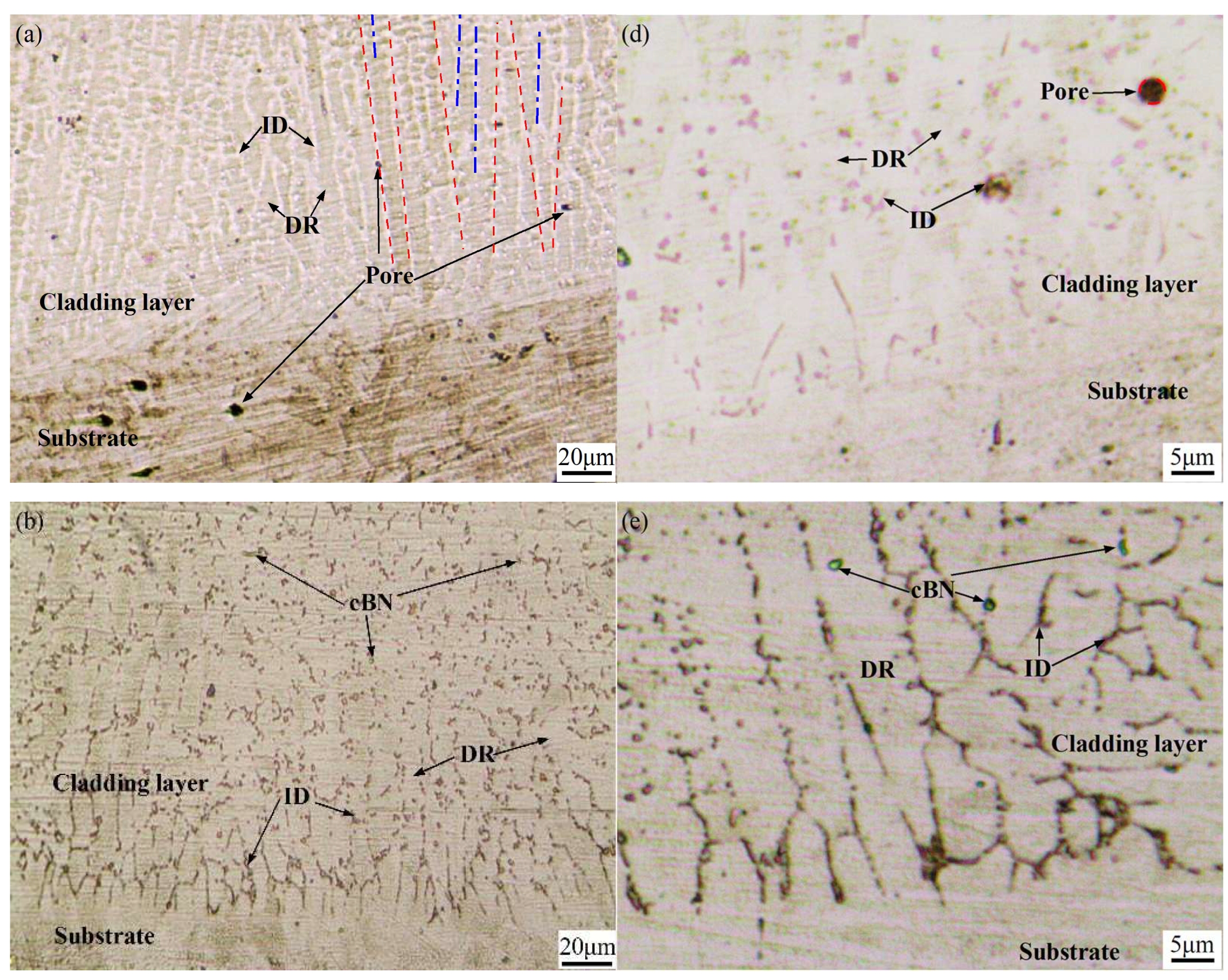
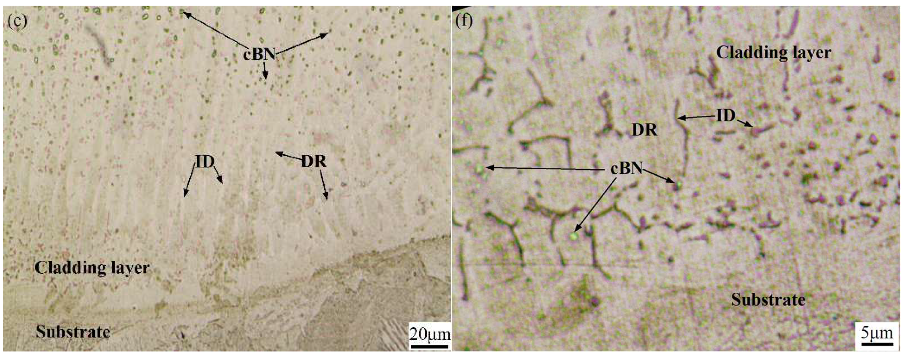
Figure 4 shows metallographic photographs of the cross-sections of CoCuNiTi + x cBN (x = 0.0, 0.5, and 1.0 wt.%) clad layers. All three alloys exhibit typical dendritic structures. As shown in Figure 4, within the cladding layer near the substrate, the columnar crystals grow almost perpendicular to the fusion line. This is because the internal heat of the alloy melt is rapidly dissipated, primarily through thermal conduction toward the cooler substrate. The temperature gradient in the direction perpendicular to the fusion line is the largest; therefore, the growth of columnar crystals also tends to be perpendicular to the fusion line. Compared with the zone above the cladding layer, the primary dendrite spacing of the columnar crystals near the fusion line is relatively smaller. This is because the higher undercooling near the fusion line allows more grains within the alloy melt to satisfy the undercooling required for solid-phase precipitation, resulting in columnar crystals with relatively smaller dendrite spacings. As the columnar grains grow and gradually move away from the fusion line, the more favorably oriented columnar grains grow faster, thereby hindering the growth of less favorably oriented columnar grains, a process known as “preferential growth” (see Figure 4d–f). Furthermore, the heat dissipation of the alloy melts at the front of the solid–liquid interface far from the fusion line is carried out through the adjacent columnar crystals. Because the columnar crystals on the solid side of the solid–liquid interface are newly precipitated, the temperature difference between them and the liquid metal at the front of the solid–liquid interface is relatively small. This indicates a decrease in the temperature gradient and solid-phase precipitation rate. Consequently, it is easy to make the columnar crystal coarse at high temperatures for a long time and then form a dendritic structure with a “narrow-bottomed, wide-top” (see the red dashed lines in Figure 4a). When the dendrite width is excessively large, the atomic diffusion distance at the center of the dendrite front is larger than that at the junction of adjacent dendrites. Therefore, the diffusion of solute atoms at the center is more difficult than that at the junction, which easily causes solute atoms to enrich at the center of the dendrite front. This spontaneously adjusts the dendrite spacing, resulting in a “pitting” phenomenon (see the blue dot-dash line in Figure 4a). Because the density of cBN (3.48 g/cm3) is lower than that of metal elements [37], it easily floats above the alloy melt. This provides more substrates for the heterogeneous nucleation of the alloy melt containing cBN particles, which is beneficial for reducing the undercooling required for the precipitation of the alloy above the cladding layer. Consequently, rapid nucleation occurs even at lower undercooling levels. Therefore, no “pitting” phenomenon is observed in the upper region of the cladding layer containing cBN particles. Furthermore, with an increase in the cBN content, the boundary between the DR and interdendrite (ID) regions gradually becomes blurred, and the ID region progressively decreases. This aligns with the rapid reduction in the relative content of the minor phases, as shown in Table 1. Moreover, evident pore defects were observed in the microstructure of the CoCuNiTi alloy, whereas none were detected in the cBN-added samples. This is because the addition of cBN particles can cause the alloy melt to precipitate rapidly at a higher temperature, enabling the liquid metal to swiftly fill and weld the pore defects caused by volume shrinkage.
Figure 4.
Metallographic photographs of the cross-sections of CoCuNiTi + x cBN (x = 0.0, 0.5, and 1.0 wt.%) cladding layers at different magnifications: (a,d) x = 0.0, (b,e) x = 0.5 wt.%, (c,f) x = 1.0 wt.%. Note: The red dashed lines in (a) represent the growth direction of the dendrites, while the blue dot dash lines represent the spontaneously adjusted dendrite spacing.
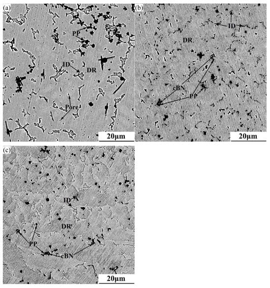
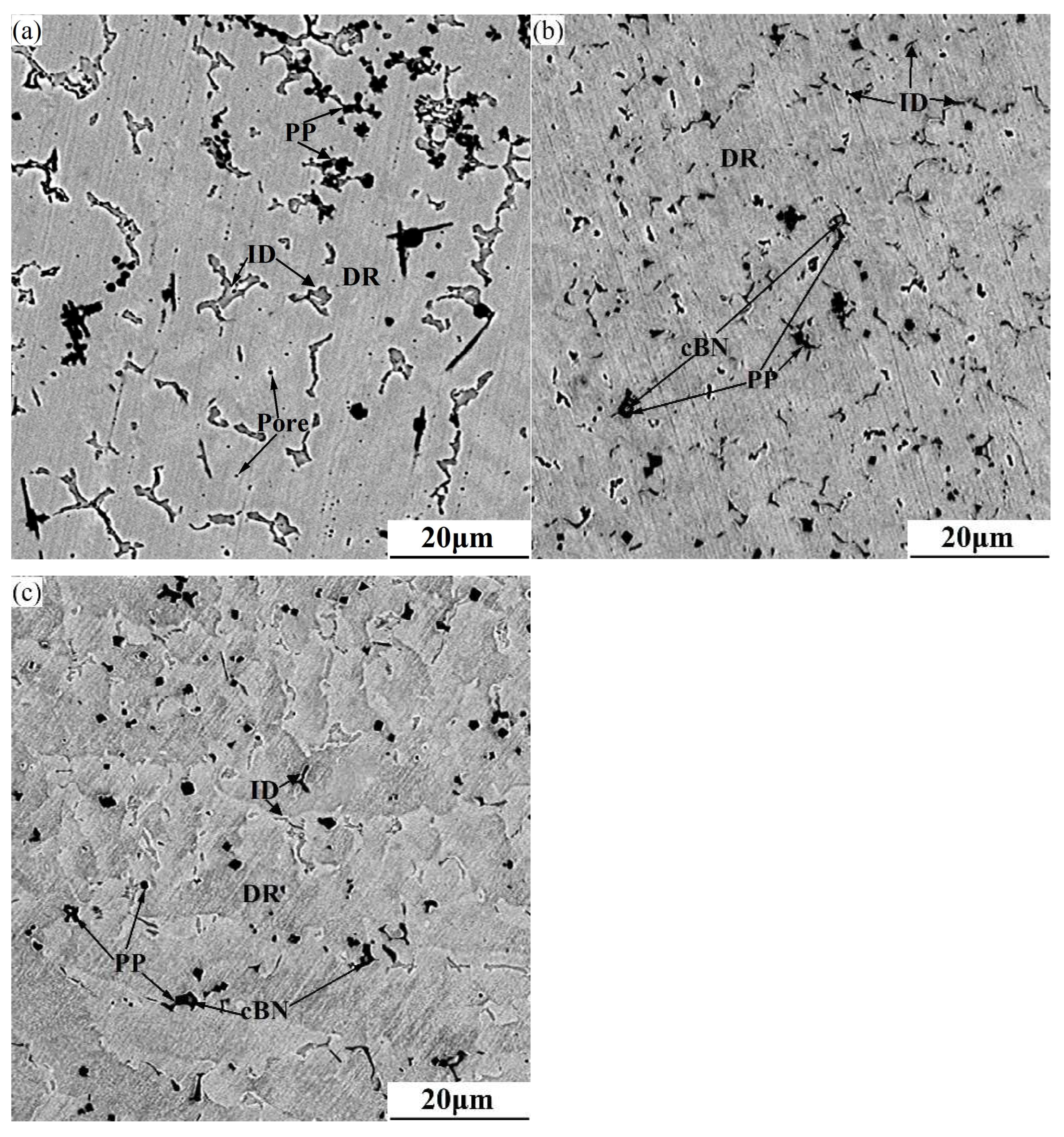
Figure 5 shows scanning electron microscope images of CoCuNiTi + x cBN (x = 0.0, 0.5, and 1.0 wt.%) HEACs. As shown in Figure 5, the microstructures of all three alloys consist of primary phase (PP), dendrite, and interdendrite regions. During the cladding process, a certain degree of “excavation effect” occurs on the substrate. To better analyze the composition distribution of the alloying elements, the substrate composition was deducted during the energy dispersive spectroscopy analysis of the alloy coating. The EDS results are listed in Table 5. As shown in Table 5, Ti exhibits the highest content in the primary phases of all three alloys, Co is enriched in the dendrite regions, and Cu is enriched in the interdendrite regions. The highest concentration of Ti (1660 °C) in the primary phase stems from its highest melting point among all the metal elements. During the cooling of the alloy melt, it can preferentially meet the undercooling requirements for solid-phase precipitation, thereby achieving the highest concentration in the primary phase. After adding cBN solid particles with higher melting point, it can provide more substrates for heterogeneous nucleation of Ti element with the highest melting point among metal elements, facilitating the abundant precipitation of Ti-rich primary phases at lower undercooling levels. The decrease in the undercooling required for solid-phase precipitation means that it can be precipitated at higher temperatures, significantly increasing atomic diffusion rates and reducing the diffusion time for elements required for primary phase growth. According to the Arrhenius equation [38,39], the viscosity of liquid metals decreases exponentially with increasing temperatures. This reduction in viscosity enhances the fluidity of the alloy melt. At higher temperatures, the probability of a free and relatively uniform distribution of the primary phase in the alloy melt is greatly increased. This is consistent with the relatively uniform distribution of the primary phases observed in the cBN-containing samples, as shown in Figure 5. Co (1495 °C) is enriched in the dendrite regions primarily because its melting point is second only to that of Ti. To reduce precipitation resistance, Co is preferentially attached to the surface of the Ti-rich phase billet for heterogeneous nucleation, resulting in higher Co concentrations within the dendrite regions growing around the primary phases. Ni (1453 °C) has a melting point between those of Co and Cu (1083 °C) and exhibits no negative enthalpy of mixing with either Co or Cu. Consequently, it struggles to form close atomic clusters with Co/Cu in the alloy melt. Therefore, Ni precipitation is highly susceptible to factors such as precipitation temperature, cooling rate, and melt environment, leading to concentration fluctuations of Ni in the dendrite and interdendrite regions. The enrichment of Cu in the interdendrite regions stems from its low melting point among all metal elements. The interdendrite regions solidify later, readily becoming enrichment regions for low-melting-point alloying elements, which is consistent with literature reports [40,41]. To better analyze the segregation degree of each alloy element and alloy, the element segregation coefficient (Ki) and the average segregation coefficient (Ka) are introduced [33],
where ξ represents the directional precipitation. When the elements are enriched in the DR region, the value of ξ is 1; conversely, when ID is enriched, ξ takes −1. CID and CDR denote the concentrations of the same element in the ID and DR regions, respectively. A larger absolute value of Ki indicates a greater concentration difference of the same element between the ID and DR regions. A higher Ka value indicates more severe overall segregation of elements in the alloy. The segregation coefficients for each alloy element, calculated using Equation (12), are listed in Table 5. As shown in Table 5, the segregation coefficients of Co in all three alloys are positive, indicating its enrichment in the DR regions; conversely, the segregation coefficients of Cu are negative, suggesting its enrichment in the ID regions. The segregation coefficient of Ni in the cBN-containing sample exhibits significant fluctuations, consistent with the above analysis results. With increasing cBN content, the segregation coefficient of Ti gradually decreases, primarily because of the rapid increase in its content in the primary phase caused by the addition of cBN particles. Because both B and N are ultralight elements, their detection sensitivity is low owing to physical mechanisms (such as low fluorescence yield and low-energy X-rays) and technical limitations (such as detector windows and energy resolution) [42]. Therefore, B and N elements are not considered when calculating the average segregation coefficient. Additionally, the removal of B and N is more conducive to comparing the overall segregation degree of metal elements in the sample. Using Equation (9) and excluding B and N, the average segregation coefficients of CoCuNiTi + x cBN (x = 0.0, 0.5, and 1.0 wt.%) HEACs were calculated to be 21.39%, 11.33%, and 12.80%, respectively. It is evident that the addition of cBN significantly reduces the average segregation coefficient of the samples. When the content of cBN increases to 1.0 wt.%, the average segregation coefficient of the sample increases slightly. This is mainly related to the substantial increase in Ti content in the primary phase, which leads to a corresponding decrease in the concentration near the dendrite regions.
Figure 5.
SEM images of CoCuNiTi + x cBN (x = 0.0, 0.5, and 1.0 wt.%) alloys. (a) x = 0.0 wt.%; (b) x = 0.5 wt.%; (c) x = 1.0 wt.%.
Table 5.
EDS results of CoCuNiTi + x cBN (x = 0.0, 0.5, and 1.0 wt.%) HEACs.
3.3. Wear Behavior
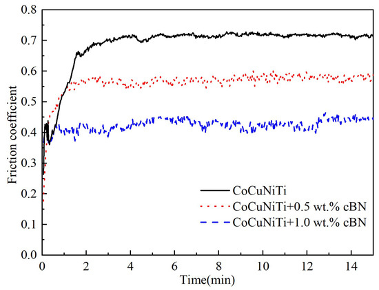
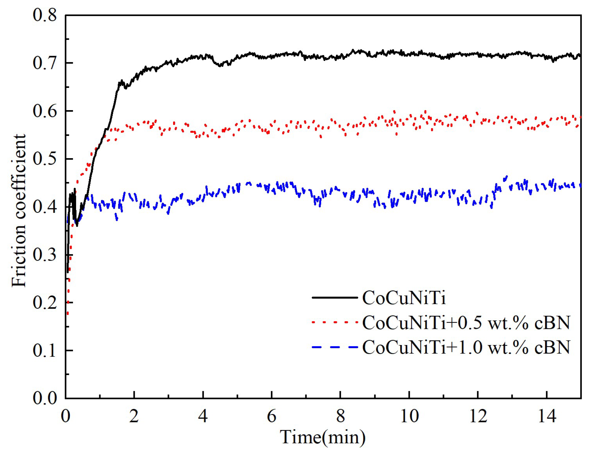
Figure 6 shows the wear behavior curves of CoCuNiTi + x cBN (x = 0.0, 0.5, and 1.0 wt.%) HEACs. As the friction time increases, the friction coefficient first rises rapidly before stabilizing. During the initial stage (running-in stage), the friction coefficient increases sharply from an initial low value owing to significant discrepancies between the nominal and actual contact areas. The actual contact between the sample and the friction pair is mainly the top of the asperity on the surface of the sample, resulting in a very high local contact stress. This readily causes plastic deformation of the asperity and forms cold-welded bonds with the asperity of the friction pair during the friction process. After the shear failure of these bonds, newly formed asperities re-adhere, creating a “bonding-shear” cycle [43,44]. Each shear event consumes energy, causing the friction resistance to surge abruptly and the friction coefficient to rise rapidly. After approximately 1.5 min, the friction coefficients of the three alloys tend to be gentle and enter the steady-state wear stage. The friction coefficients of CoCuNiTi + x cBN (x = 0.0, 0.5, and 1.0 wt.%) HEACs are 0.6913, 0.5558, and 0.4156, respectively. As the cBN content increases, the friction coefficient of the samples gradually decreases, which is consistent with the phenomenon reported in most studies [45,46,47] that the addition of superhard phases enhances the wear resistance of alloys. The reason why the addition of cBN improves the wear resistance of the alloy is that: (1) During friction, the micro-convex structure formed by extremely hard cBN particles distributed on the top of the coating surface (see Figure 3b,c) bears the primary load and reduces the direct contact between the alloy coating and the friction pair [48]. The area bearing the contact stress changes from adhesive wear dominant by the CoCuNiTi coating to elastic/slightly plastic deformation dominated by cBN particles. This hard-point support mechanism significantly enhances wear resistance. (2) The alloy melt uses cBN particles as the heterogeneous nucleation substrates and precipitates and grows closely around its surface. Under high-temperature conditions, B and N atoms with smaller atomic radii diffuse into interstitial sites in the high-entropy alloy lattice structure via solid-state diffusion, thereby generating solid-solution strengthening effects. (3) The interface between the DR and ID is usually the weak part of the performance [49]. As the cBN particle content increases, the relative content difference between the two phases of the alloy gradually increases, indicating that the content of a single main phase increases significantly and the interface between the two phases decreases significantly. This promotes an overall improvement in the alloy performance. (4) cBN exhibits high thermal conductivity [50], enabling the rapid conduction of friction heat from cBN particles to the substrate. This facilitates a reduction in the coating surface temperature and mitigates the softening effects caused by elevated temperatures, consistent with reference [51] indicating superior wear resistance in coatings containing cBN particles. When the cBN addition reaches 1.0 wt.%, the alloy exhibits the lowest friction coefficient and optimal wear resistance. This is primarily attributed to the combined effects of hard particle support, solid-solution strengthening, phase-interface reduction, and high thermal conductivity of cBN.
Figure 6.
Friction coefficient versus time for CoCuNiTi + x cBN (x = 0.0, 0.5, and 1.0 wt.%) HEACs.
3.4. Corrosion Behavior
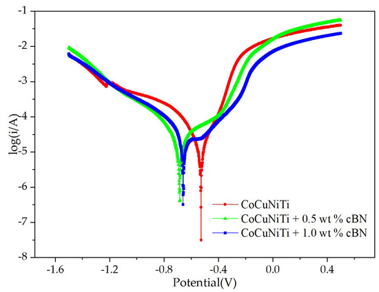
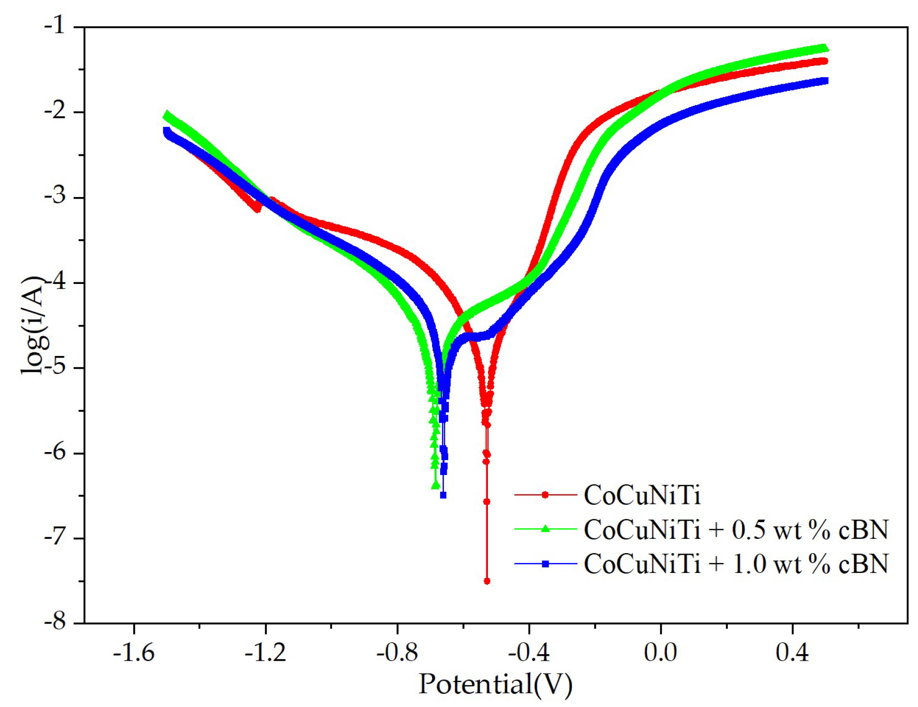
Figure 7 shows the polarization curves of CoCuNiTi + x cBN (x = 0.0, 0.5, and 1.0 wt.%) HEACs in a 3.5% NaCl solution. As shown in Figure 7, none of the three alloys exhibit a distinct passivation region, indicating active dissolution. Obvious pore defects can be observed in the microstructure of the CoCuNiTi alloy (see Figure 3a and Figure 4a). Although no obvious pore defects were observed in the cBN-containing samples, agglomeration between cBN particles and the formation of microcracks is prone to occur [27,28]. Defects such as pores and microcracks easily cause Cl− ions in the etching solution to be adsorbed on the surface and enter the interior of the coating to be eroded, preventing the formation of a dense passivation film on the sample surface. The polarization curves were fitted by extrapolation method, and the self-corrosion current density (icorr), self-corrosion potential (Ecorr), anode slope (βa) and cathode slope (βc) of CoCuNiTi + x cBN (x = 0.0, 0.5, and 1.0 wt.%) HEACs were obtained. The fitting results are listed in Table 6. The polarization resistance (Rp) and annual corrosion rate (Kcorr) in Table 6 are calculated using the following equations [25],
where q is a constant (≈3272 mm·A−1·cm−1·year−1), EW is the electrode equivalent (g), ρ is the mass density (g·cm−3), fi is the mass fraction of the i-th element, ni is the number of electrons exchanged by the i-th element (mol−1), and Ai is the atomic mass of the i-th element (g·mol−1). Although the CoCuNiTi sample has the highest corrosion potential and lowest self-corrosion current density, its annual corrosion rate is the largest. This anomalous phenomenon has also been similarly reported in other alloy coatings [52,53]. Typically, a higher corrosion potential indicates a lower thermodynamic corrosion tendency, whereas a lower self-corrosion current density suggests a reduced kinetic corrosion tendency. However, due to the obvious pores in the microstructure of CoCuNiTi, its corrosion resistance is significantly reduced, resulting in the highest annual corrosion rate. Additionally, the sample with 1.0 wt.% cBN exhibits the largest anodic slope (βa), indicating the greatest hindrance to anodic solution reactions at the same overpotential. As shown in Table 6, with an increase in cBN content, βa increases rapidly from 137.34 mV (x = 0.0) to 391.39 mV (x = 1.0). On the one hand, it is because of the geometric shielding and the “labyrinth effect”. The insulating cBN particles embedded in the coating surface effectively reduce the electrochemically active area, forcing the corrosive medium to diffuse along a tortuous path. Additionally, the addition of CBN reduces surface pore defects, thereby decreasing the number of penetration channels, which contributes to the “labyrinth effect.” This physical barrier kinetically delays the anodic dissolution process, which is manifested as an increase in the Tafel slope [54]. In contrast, the increase in βa is related to the current density redistribution and kinetic response of the heterogeneous interfaces. The heterogeneous composite electrode, composed of a conductive substrate and insulating cBN particles, causes a restructuring of the surface current density. The current line tends to bypass the high resistance cBN particles and is locally concentrated in the metal substrate region, which induces rapid passivation of the particle boundary region [55]. Therefore, the Tafel slope obtained by fitting the macroscopic polarization curve is a highly “averaged” apparent value, reflecting the overall degree of hindrance in the charge transfer process on a geometrically and chemically heterogeneous surface. The high βa value is related to factors such as geometric shielding, the “labyrinth effect,” current density redistribution, and the kinetic response of heterogeneous interfaces caused by the addition of CBN particles, which is beneficial for improving the corrosion resistance of the coating. This is also in good agreement with the trend of gradually decreasing annual corrosion rates shown in Table 6 (from 16.42 × 10⁻² mm/year to 15.44 × 10⁻² mm/year). The sample containing 0.5 wt.% cBN exhibits the highest polarization resistance (Rp), primarily due to its maximum product of βc and βa. With an increase in cBN particles, the annual corrosion rate of the sample gradually decreases. This may be attributed to the dispersed cBN particles hindering the uniform penetration of the corrosive solution and the complexity of the anodic dissolution process (the βa values for the three alloys exhibit the greatest difference) [53,56]. In addition, as shown in Table 6, the self-corrosion potential of the alloy shifts significantly toward more negative values after the addition of cBN. According to mixed potential theory [57], corrosion potential is the result of the kinetic equilibrium between anodic dissolution and cathodic reduction reactions. The coating surface containing insulating cBN particles not only reduces the effective area of the anodic reaction but also inhibits the kinetic process of the cathodic reduction reaction. As shown in Table 6, the anodic Tafel slope βa increases significantly (by at least 123.89%) after cBN addition, indicating that the anodic dissolution reaction is strongly suppressed. In contrast, the cathodic Tafel slope βc changes relatively little (no more than 22.17%). When the cathodic reaction is inhibited, the cathodic polarization curve shifts downward, causing the intersection point with the anodic curve (i.e., Ecorr) to move in a more negative direction. The displacement of the corrosion potential reflects the relative change in the kinetics of the cathode and anode. A negative shift in this value does not directly indicate reduced corrosion resistance but rather reflects the inhibition of cathodic kinetics [58]. Furthermore, the effective electrochemically active area (Aeff) on the surface of the coating containing cBN particles was significantly reduced. In electrochemical testing, icorr is an apparent value calculated based on the geometric area (Ageo), whereas the actual local corrosion current density is higher than the apparent value because of the reduction in Aeff [55]. Furthermore, the average segregation coefficient (21.39%) of the CoCuNiTi coating is notably high. The more serious the element segregation, the easier it is to form micro-galvanic couples between the dendrite and interdendrite regions, thereby promoting localized corrosion. This finding is consistent with that of the literature [59].
Figure 7.
Polarization curves of CoCuNiTi + x cBN (x = 0.0, 0.5, and 1.0 wt.%) HEACs.
Table 6.
Electrochemical parameters of CoCuNiTi + x cBN (x = 0.0, 0.5, and 1.0 wt.%) HEACs.
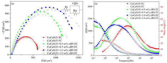
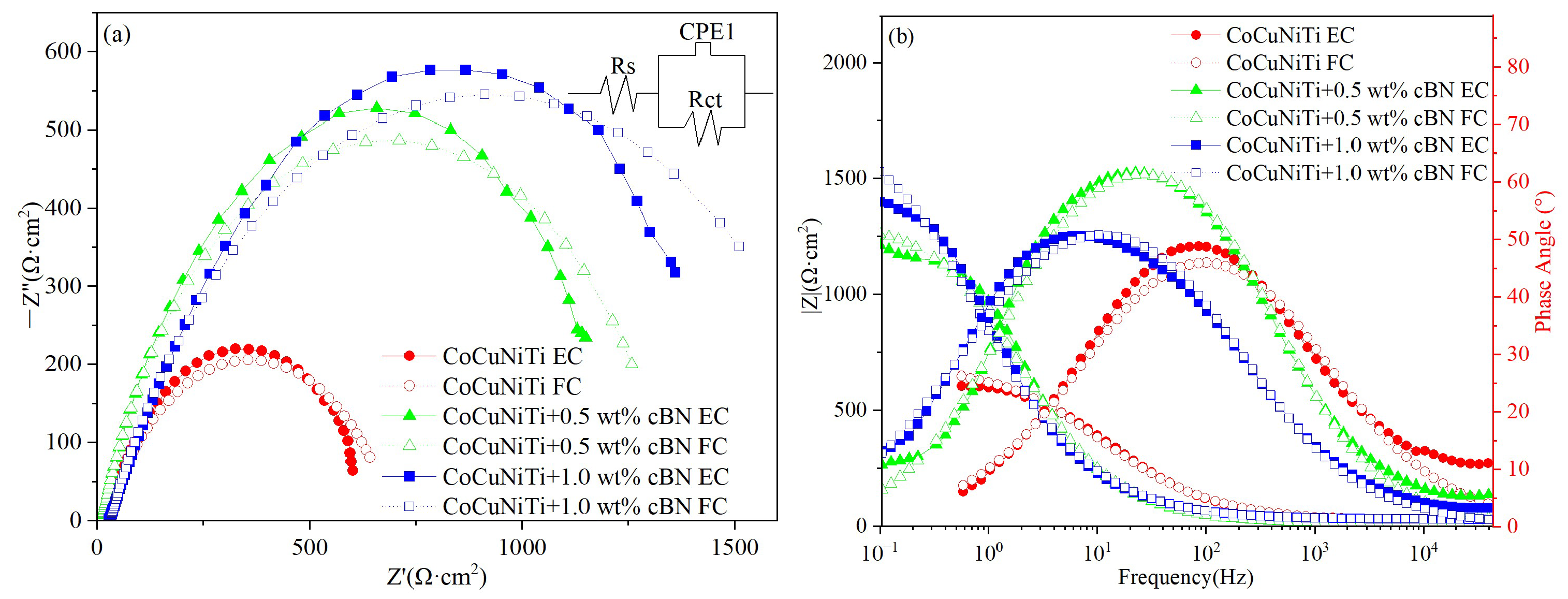
Figure 8 shows the EIS plots of CoCuNiTi + x cBN (x = 0.0, 0.5, and 1.0 wt.%) HEACs in a 3.5% NaCl solution. As shown in Figure 8a, the Nyquist plots of all three alloys exhibit a flattened semicircular capacitive arc, indicating that the corrosion process is primarily controlled by a single time constant dominated by charge transfer processes [25]. As the cBN content increases, the radius of the capacitive arc gradually increases, indicating a progressively enhanced corrosion resistance. This trend aligns with the calculated annual corrosion rates in Table 6. Table 7 summarizes the circuit fitting results obtained from the illustration in Figure 8a. In Table 7, Rs, CPE1, and Rct represent the solution resistance, constant phase element, and charge-transfer resistance, respectively. The impedance ZCPE can be expressed as [25],
where Y0 is the admittance constant, j is the imaginary unit, and ω is the angular frequency, m is the dissipation exponent, whose value ranges between −1 and 1. m = 1 and m = −1 represent ideal capacitive circuits and ideal inductive circuits, respectively. m = 0.7 represents a porous electrode circuit. A smaller difference between m and 1 indicates a higher uniformity and density of the electrode surface [25]. As shown in Table 7, CoCuNiTi exhibits the smallest m value, that is, the largest difference from 1, indicating that the electrode surface of the sample is significantly influenced by the porous structure. This finding is consistent with the obvious pore defects observed in the sample, as depicted in Figure 3 and Figure 4. The m value is highest for the sample containing 0.5 wt.% cBN. When the cBN content is further increased, the m value decreases significantly, indicating that excessive cBN particles reduce the dense degree of the sample surface and increase the influence of the porous structure. This aligns with the previous analysis, which concludes that cBN particles tend to agglomerate and generate microcracks. Rct directly reflects the difficulty of electrochemical reactions at the metal/electrolyte interface [60]. As the cBN content increases, the Rct of the samples gradually increases, indicating that the addition of cBN particles significantly hinders the charge transfer process of the metal ions. As shown in Figure 8b, the phase angle peak values of the cBN-containing samples shift noticeably toward lower frequencies, suggesting a decrease in the interface capacitance or an increase in the resistance. The CoCuNiTi sample exhibits the smallest phase angle peak value, indicating that the surface of the sample is rough or has a dispersion effect. The phase angle peak value of the sample with 0.5 wt.% cBN is the largest, indicating that it is closest to the ideal capacitance behavior and the surface is the most uniform. This aligns with the observations in Figure 3 and Figure 4 and the analysis of m. When the cBN content is further increased (x = 1.0 wt.%), the phase angle peak of the sample decreases. This is because the height of the phase angle peak in the Bode plot reflects the degree of ideal capacitive behavior at the electrode/solution interface and the uniformity of the surface [61]. As shown in Table 7, compared with the sample containing 0.5 wt.% cBN, the m value (0.7021) of the 1.0 wt.% cBN sample decreased. This is attributed to the increase in element distribution segregation and decrease in surface uniformity caused by the agglomeration of cBN particles. As shown in Table 7 and Figure 8b, the change rule of the phase angle is consistent with that of the m value, which is consistent with the findings in the literature [62] that the m-value directly determines the height of the phase angle peak in the Bode plot.
Figure 8.
Nyquist (a) and Bode (b) plots of CoCuNiTi + x cBN (x = 0.0, 0.5, and 1.0 wt.%) HEACs in a 3.5% NaCl solution.
Table 7.
EIS parameters of CoCuNiTi + x cBN (x = 0.0, 0.5, and 1.0 wt.%) HEACs.
4. Conclusions
CoCuNiTi + x cBN (x = 0.0, 0.5, and 1.0 wt.%) laser cladding layers were successfully prepared on a 45-steel substrate surface. The effects of varying cBN contents on the phase composition, microstructure, wear, and corrosion resistance were thoroughly analyzed and discussed. The main conclusions are as follows:
- (1)
- The CoCuNiTi alloy exhibits a dual-phase structure composed of FCC main phase and BCC phase. As the cBN content increases, the BCC phase gradually becomes predominant, transforming into a dual-phase structure with BCC main phase and FCC phase. The space groups, lattice constants, cell volumes, and relative contents of the two phases in CoCuNiTi + x cBN (x = 0.0, 0.5, and 1.0 wt.%) alloys were determined through whole-pattern fitting and Rietveld refinement calculations. Their refinement weight factors are 6.82%, 2.86%, and 1.42%, respectively. The lattice constants and cell volumes of the FCC and BCC phases in the cBN-containing samples are significantly reduced. The microstructures of CoCuNiTi + x cBN (x = 0.0, 0.5, and 1.0 wt.%) alloys are composed of primary phase, dendrite regions, and interdendrite regions. Ti, Co, and Cu are enriched in the primary phase, dendrite regions, and interdendrite regions, respectively. The average segregation coefficients for CoCuNiTi + x cBN (x = 0.0, 0.5, and 1.0 wt.%) HEACs are 21.39%, 11.33%, and 12.80%, respectively.
- (2)
- The friction coefficients of CoCuNiTi + x cBN (x = 0.0, 0.5, and 1.0 wt.%) alloy initially increase rapidly with friction time, stabilizing after approximately 1.5 min. Their friction coefficients are 0.6913, 0.5558, and 0.4156, respectively. When the cBN content is 1.0 wt.%, the sample exhibits the lowest friction coefficient and optimal wear resistance.
- (3)
- CoCuNiTi + x cBN (x = 0.0, 0.5, and 1.0 wt.%) HEACs have no obvious passivation zone, which belongs to active dissolution. With the increase in cBN particles, the capacitive arc radius of the sample gradually increases, and the annual corrosion rate gradually decreases, indicating that the CoCuNiTi + 1.0 wt.% cBN coating provides the best corrosion resistance.
Author Contributions
Conceptualization, M.M., C.L., Z.W., L.Z., and D.Z. (Deliang Zhang); methodology, M.M., X.Z., Z.W., Y.X. and D.Z. (Dachuan Zhu); software, M.M., C.L., Y.D. and L.Z.; validation, M.M., C.L., Y.D. and L.Z.; formal analysis, M.M., X.Z., C.Z. and Y.X.; investigation, M.M., Z.W., L.Z. and Y.X.; resources, M.M., X.Z., Z.W., C.Z. and Y.X.; data curation, M.M. and L.Z.; writing—original draft preparation, M.M.; writing—review and editing, X.Z., C.L., Y.D., D.Z. (Deliang Zhang) and D.Z. (Dachuan Zhu); visualization, M.M., Z.W. and L.Z.; supervision, X.Z., C.L., Z.W., D.Z. (Deliang Zhang) and D.Z. (Dachuan Zhu); project administration, Y.D., Y.X. and C.Z.; funding acquisition, M.M., Y.D., Z.W., C.Z. and D.Z. (Deliang Zhang). All authors have read and agreed to the published version of the manuscript.
Funding
This work was supported by the Henan Province Science and Technology Research Project (252102221051, 252102231020), Henan Province University-Enterprise Collaborative Innovation Program (26AXQXT016), Key Scientific Research Projects of Henan Province (25A510001), Key Research and Development Special Project of the Science and Technology Program of Nanyang (24ZDYF018).
Institutional Review Board Statement
Not applicable.
Informed Consent Statement
Not applicable.
Data Availability Statement
The original contributions presented in this study are included in this article. Further inquiries can be directed to the corresponding author.
Conflicts of Interest
The authors declare no conflicts of interest.
References
- Zhao, W.; Dai, D.; Wu, X.; Liu, Y.; Xu, P.; Gao, Y.; Qu, W.; Wang, Q.; Zhang, Q.; Liu, X. Upgrading Mechanical Property and Corrosion Resistance of a Low Cost 45 Steel by Remelting a Cr Film of ~1 μm in Thickness. J. Mater. Res. Technol. 2023, 26, 8961–8971. [Google Scholar] [CrossRef] [Scilit]
- Huang, G.; Qu, L.; Lu, Y.; Wang, Y.; Li, H.; Qin, Z.; Lu, X. Corrosion Resistance Improvement of 45 Steel by Fe-Based Amorphous Coating. Vacuum 2018, 153, 39–42. [Google Scholar] [CrossRef] [Scilit]
- Cai, W.; Meng, F.; Gao, X.; Hu, J. Effect of QPQ Nitriding Time on Wear and Corrosion Behavior of 45 Carbon Steel. Appl. Surf. Sci. 2012, 261, 411–414. [Google Scholar] [CrossRef] [Scilit]
- Liu, H.; Wang, C.; Zhang, X.; Jiang, Y.; Cai, C.; Tang, S. Improving the Corrosion Resistance and Mechanical Property of 45 Steel Surface by Laser Cladding with Ni60CuMoW Alloy Powder. Surf. Coat. Technol. 2013, 228, S296–S300. [Google Scholar] [CrossRef] [Scilit]
- Gu, T.; Zhang, S.; Zhao, Y.; Yang, Y.; Liu, H.; Wu, L.; Liu, J.; Hou, H. Novel Method to Improve the Microstructure and Mechanical Properties of 45 Steel. Met. Mater. Int. 2022, 28, 833–840. [Google Scholar] [CrossRef] [Scilit]
- Liu, X.; Jiang, F.; Chen, Z.; Dong, W.; Jiang, G.; Dong, T.; Sun, W.; Liu, L.; Guo, C. Microstructure and Corrosion Property of TC4 Coating with Al0.5CoCrFeNi High-Entropy Alloy Interlayer by Laser Cladding. Surf. Coat. Technol. 2024, 476, 130190. [Google Scholar] [CrossRef] [Scilit]
- Kong, L.; Shi, C.; Hao, X.; Wang, S.; Huo, Y.; Zhu, Z.; Sun, J. Effect of Ti and Mo Content Changes on Microstructure and Properties of Laser Cladding FeCoCrNiMn High Entropy Alloy Coatings. Intermetallics 2024, 175, 108509. [Google Scholar] [CrossRef] [Scilit]
- Chen, Z.; Su, Y.; Li, H.; Wang, X.; Liu, L.; Yang, Z.; Tang, H.; Lv, W.; Chen, J.; Li, N.; et al. Synchronous Ultrasonic Impact Assisted Laser Cladding CoCrFeNiMo High Entropy Alloy Coating: Microstructure and Wear Property. Tribol. Int. 2025, 201, 110207. [Google Scholar] [CrossRef] [Scilit]
- Liu, H.; Wu, D.; Wang, W.; Chen, P.; Li, D.; Yang, H.; Hao, J. Tribological Failure Mechanisms and Wear Resistance Optimization in CoCrFeNi (MoNbTi)x High-Entropy Alloy Coatings Prepared by Laser Cladding. Eng. Fail. Anal. 2025, 179, 109823. [Google Scholar] [CrossRef] [Scilit]
- Zhang, K.; Wang, W.; Liu, W.; Liu, C.; Geng, J.; Wang, H.; Bian, H. Effect of Sm2O3 Particles on Microstructure and Properties of FeCoNiCrMn Composite Coating by Laser Cladding. Mater. Chem. Phys. 2024, 317, 129168. [Google Scholar] [CrossRef] [Scilit]
- Duan, B.; Lin, N.; Zhao, H.; Zhou, L.; Wang, X.; Ma, G.; Wang, H.; Shi, Q.; Wu, Y. Microstructure and Tribological Performance of FeCrNiMox Medium-Entropy Alloy (MEA) Coatings by High-Speed Laser Cladding: Effect of Molybdenum Content. J. Alloys Compd. 2025, 1031, 181001. [Google Scholar] [CrossRef] [Scilit]
- Zhang, Z.; Niu, W.; Lei, Y.; Zheng, Y. The Effect of SiC Content on the Microstructure and Mechanical Properties of AlCoCrFeNiTi Laser Cladding High-Entropy Alloy Coatings. J. Therm. Spray Technol. 2025, 34, 1195–1207. [Google Scholar] [CrossRef] [Scilit]
- Wu, J.; Yuan, G.; Jiao, Z.; Yao, Y.; Huang, W.; Zhou, K.; Ma, L.; Wei, Q. Optimizing Interface Microstructure of Diamond Reinforced Al Matrix Composites via Nano-Scale Si-Al Coatings Towards Enhanced Thermophysical Performance. Appl. Surf. Sci. 2025, 693, 162786. [Google Scholar] [CrossRef] [Scilit]
- Müller, M.; Gerdt, L.; Schrüfer, S.; Riede, M.; López, E.; Brueckner, F.; Leyens, C. Laser-Based Directed Energy Deposition and Characterisation of cBN-Reinforced NiAl-Based Coatings. Int. J. Adv. Manuf. Technol. 2024, 134, 657–675. [Google Scholar] [CrossRef] [Scilit]
- Wang, H.; Zhang, W.; Peng, Y.; Zhang, M.; Liu, S.; Liu, Y. Microstructures and Wear Resistance of FeCoCrNi-Mo High Entropy Alloy/Diamond Composite Coatings by High Speed Laser Cladding. Coatings 2020, 10, 300. [Google Scholar] [CrossRef] [Scilit]
- Zhang, Y.; Han, T.; Xiao, M.; Shen, Y. Tribological Behavior of Diamond Reinforced FeNiCoCrTi0.5 Carbonized High-Entropy Alloy Coating. Surf. Coat. Technol. 2020, 401, 126233. [Google Scholar] [CrossRef] [Scilit]
- Peng, Y.; Kong, Y.; Zhang, W.; Zhang, M.; Wang, H. Effect of Diffusion Barrier and Interfacial Strengthening on the Interface Behavior Between High Entropy Alloy and Diamond. J. Alloys Compd. 2021, 852, 157023. [Google Scholar] [CrossRef] [Scilit]
- Rommel, D.; Scherm, F.; Kuttner, C.; Glatzel, U. Laser Cladding of Diamond Tools: Interfacial Reactions of Diamond and Molten Metal. Surf. Coat. Technol. 2016, 291, 62–69. [Google Scholar] [CrossRef] [Scilit]
- Liu, Y.; He, D.; Kou, Z.; Liu, F.; Wang, P.; Hu, Q.; Liang, A. Hardness and Thermal Stability Enhancement of Polycrystalline Diamond Compact Through Additive Hexagonal Boron Nitride. Scr. Mater. 2018, 149, 1–5. [Google Scholar] [CrossRef] [Scilit]
- Yu, Y.; Li, Y.; Tan, N.; Mou, H.; Tong, Y.; Xing, Z.; Cai, Z.; Wang, H. Influence of cBN on the Microstructure and Tribology Properties of (CoCrNi)94Al3Ti3 Medium-Entropy Alloy Coating Prepared by High-Speed Laser Cladding: The Evolution and Strengthening Mechanism of cBN. Ceram. Int. 2024, 50, 22041–22049. [Google Scholar] [CrossRef] [Scilit]
- Wang, X.; Luo, J.; Li, Y.; Mou, H.; Tong, Y.; Cai, Z.; Xing, Z.; Wei, S.; Yu, Y. Properties of Laser Cladding (NiCoCr)94Al3Ti3-cBN-hBN Hard Self-Lubricating Ceramic Coating. Ceram. Int. 2024, 50, 13761–13769. [Google Scholar] [CrossRef] [Scilit]
- Ma, M.; Wang, Z.; Zhu, C.; Dong, Y.; Liu, L.; Zhao, L.; Cui, Q.; Zhu, D.; Zhang, D. Effect of Mn Doping on Microstructure and Corrosion Behavior of CoCuNiTi High-Entropy Alloy Coatings. Crystals 2025, 15, 29. [Google Scholar] [CrossRef] [Scilit]
- Okumuş, M.; Kaya, F. Effect of Ti Content and Ball-Milling Time on the Microstructural, Thermal, and Microhardness Properties of AlCoCuNiTi High Entropy Alloys. Mater. Chem. Phys. 2024, 311, 128591. [Google Scholar] [CrossRef] [Scilit]
- Li, Z.; Jiang, W.; Liu, Y.; Wang, E.; Wang, Z.; Zhao, F.; Dai, H. Wear and Corrosion Performance of CoCrNiTi Medium Entropy Alloy Films: A Magnetron Sputtered Architecture from Crystal to Amorphous. Surf. Coat. Technol. 2026, 519, 132931. [Google Scholar] [CrossRef] [Scilit]
- Ma, M.; Zhao, L.; Wang, Z.; Li, S.; Dong, C. Effect of CeO2 Doping on the Microstructure and Corrosion Behavior of CoCuNiTi High-Entropy Alloy Coatings. Mater. Tehnol. 2021, 55, 286–296. [Google Scholar] [CrossRef] [Scilit]
- Kurakevych, O.O.; Solozhenko, V.L. High-Pressure Design of Advanced BN-Based Materials. Molecules 2016, 21, 1399. [Google Scholar] [CrossRef] [Scilit]
- Maier, L.; Wolfrum, A.-K.; Motthey, B.; Herrmann, M.; Höhn, S.; Michaelis, A. Preparation and Microstructure of Superhard Al2O3–Cubic Boron Nitride Ceramic Composites. Open Ceram. 2025, 23, 100819. [Google Scholar] [CrossRef] [Scilit]
- Huang, Z.; Zhao, W.; Zhao, W.; Ci, X.; Li, W. Tribological and Anti-Corrosion Performance of Epoxy Resin Composite Coatings Reinforced with Differently Sized Cubic Boron Nitride (CBN) Particles. Friction 2021, 9, 104–118. [Google Scholar] [CrossRef] [Scilit]
- Ma, M.; Zhu, D.; Wang, Z.; Li, S.; Dong, C. Effect of Zr Addition on Microstructure and Wear Properties of CoCrCuFeMn High-Entropy Alloy. Adv. Eng. Sci. 2021, 53, 204–210. [Google Scholar] [CrossRef]
- Sagmiller, D.; Hartwig, J. Survey of Cryogenic Nitrogen Thermomechanical Property Data Relevant to Outer Solar System Bodies. Earth Space Sci. 2020, 7, e2019EA000640. [Google Scholar] [CrossRef] [Scilit]
- Salzmann, C.G.; Rosu-Finsen, A. The Crystallography of Pluto. IUCrJ 2020, 7, 782–783. [Google Scholar] [CrossRef] [Scilit]
- Liu, C.; Dong, F.Y.; Zhang, Y.; Yuan, X.G.; Wang, B.B.; Luo, L.S.; Su, Y.Q.; Cheng, J.; Liaw, P.K. Morphology, Microstructure, and Mechanical Properties of TiZrTa0.7NbMo Refractory High-Entropy Alloy Spherical Powder Prepared by Ultrasonic Atomization. Intermetallics 2025, 187, 109019. [Google Scholar] [CrossRef] [Scilit]
- Ma, M.; Wang, Z.; Zhou, J.; Liang, C.; Zhu, D.; Zhang, D. Effect of Ti Doping on Microstructure and Wear Resistance of CoCrCuFeMn High-Entropy Alloys. J. Mech. Eng. 2020, 56, 134–142. [Google Scholar] [CrossRef] [Scilit]
- Wang, G.Y.; Hsu, W.C.; Huang, Z.W.; Yeh, J.W.; Tsai, C.W. The Growth Activation Energy of Sigma Phase in Nonequal Molar CoCrFeNiV Low Entropy and High Entropy Alloys. J. Alloys Compd. 2025, 1017, 178863. [Google Scholar] [CrossRef] [Scilit]
- Takeuchi, A.; Inoue, A. Classification of Bulk Metallic Glasses by Atomic Size Difference, Heat of Mixing and Period of Constituent Elements and Its Application to Characterization of the Main Alloying Element. Mater. Trans. 2005, 46, 2817–2829. [Google Scholar] [CrossRef] [Scilit]
- Guo, S.; Liu, C.T. Phase Stability in High Entropy Alloys: Formation of Solid-Solution Phase or Amorphous Phase. Prog. Nat. Sci. Mater. Int. 2011, 21, 433–446. [Google Scholar] [CrossRef] [Scilit]
- Kobayashi, T.; Valizadeh, R.; Colligon, J.S.; Kanematsu, H.; Morisato, K. Method for Simulating the Thickness Distribution of a Cubic Boron Nitride Film Deposited on a Curved Substrate Using Ion-Beam-Assisted Vapor Deposition. Phys. Procedia 2012, 32, 831–839. [Google Scholar] [CrossRef] [Scilit]
- Gao, S.; Jiao, K.; Zhang, J.; Fan, X.; Liu, Z.; Zheng, A. Review on the Viscosity of Iron-Based Melts in Metallurgical Process. ISIJ Int. 2022, 62, 2172–2182. [Google Scholar] [CrossRef] [Scilit]
- Asghar, O.; da Silva, M.; Busqué, R.; Bonollo, F. Fluidity of Aluminium Foundry Alloys for Thin Wall Castings: Designing an Operating Methodology. Metals 2025, 15, 229. [Google Scholar] [CrossRef] [Scilit]
- Xian, X.; Lin, L.; Zhong, Z.; Zhang, C.; Chen, C.; Song, K.; Cheng, J.; Wu, Y. Precipitation and Its Strengthening of Cu-Rich Phase in CrMnFeCoNiCux High-Entropy Alloys. Mater. Sci. Eng. A 2018, 713, 134–140. [Google Scholar] [CrossRef] [Scilit]
- Li, B.S.; Wang, Y.P.; Ren, M.X.; Yang, C.; Fu, H.Z. Effects of Mn, Ti and V on the Microstructure and Properties of AlCrFeCoNiCu High Entropy Alloy. Mater. Sci. Eng. A 2008, 498, 482–486. [Google Scholar] [CrossRef] [Scilit]
- Bastin, G.F.; Heijligers, H.J.M. Analyzing the Light Elements in an Electron Probe Micro Analyzer. Microsc. Microanal. 1998, 4, 220–221. [Google Scholar] [CrossRef] [Scilit]
- Aghababaei, R.; Warner, D.H.; Molinari, J.-F. On the Debris-Level Origins of Adhesive Wear. Proc. Natl. Acad. Sci. USA 2017, 114, 7935–7940. [Google Scholar] [CrossRef] [Scilit] [PubMed]
- Stolarski, T.A. Analysis of the Resistance to Motion in a Sliding Contact. Wear 1994, 171, 203–209. [Google Scholar] [CrossRef] [Scilit]
- Liu, X.; Chen, M.; Shi, C.; Liu, G.; Li, H.; Wang, H.; Fan, B.; Chen, Y. Phase Evolution and Performance Analysis of PcBN Carbide Insert Prepared by Integrated Sintering with Different WC-Co Alloy Substrate. Ceram. Int. 2025, 51, 23837–23843. [Google Scholar] [CrossRef] [Scilit]
- Ren, X.; Ma, C.; Wu, C.; Deng, H.; Yin, G.; Cheng, J. Abrasive Wear Resistance of Diamond Reinforced Al0.5CoCrFeNiTi0.5 High-Entropy Alloy Coating Prepared by Laser Cladding. Tribol. Trans. 2026, 69, 338–348. [Google Scholar] [CrossRef] [Scilit]
- Yu, Y.; Li, Y.; Tan, N.; Mou, H.; Xing, Z.; Liu, J.; Liu, J.; Du, X.; Li, J.; Cai, Z.; et al. Microstructure and Performance of (CoCrNi)88Al6Ti6-cBN Composite Coatings by High-Speed Laser Cladding (HSLC): A Novel Strategy for Synergizing Wear-Resistance and Friction Reduction. Tribol. Int. 2024, 200, 110175. [Google Scholar] [CrossRef] [Scilit]
- Fan, B.; Yu, J.; Qin, T.; Wang, J.; Zhang, Y.; Chen, C.; Song, J.; Ji, H. The Influence of Friction Damage on Corrosion Resistance of Binderless WC-cBN-SiCw Composite in NaCl Solution. Crystals 2025, 15, 760. [Google Scholar] [CrossRef] [Scilit]
- Cheng, Y.; Fu, J.; Zhao, M.; Shen, Y. Research Progress on Corrosion Resistance of High-Entropy Alloys. J. Chin. Soc. Corros. Prot. 2024, 44, 1100–1116. [Google Scholar] [CrossRef]
- Shi, Y.; Chen, L.; Xin, H.; Yu, T.; Sun, Z. Investigation on the Grinding Properties of High Thermal Conductivity Vitrified Bond CBN Grinding Wheel for Titanium Alloy. Int. J. Adv. Manuf. Technol. 2020, 107, 1539–1549. [Google Scholar] [CrossRef] [Scilit]
- Huang, J.; Bi, Z.; Yang, J.; Xiang, T.; Liu, Y.; Cai, Z.; Xing, Z.; Lou, L.; Wang, H.; Li, C. Tribological Performance of High-Speed Laser-Cladded cBN Reinforced Composite Coatings: The Influence of Ag Additions. Coatings 2026, 16, 196. [Google Scholar] [CrossRef] [Scilit]
- Zhang, M.; Zhang, Y.; Dai, P.; Zhao, L.; Wu, L.; Li, S. Study on the Process Parameters and Corrosion Resistance of FeCoNiCrAl High Entropy Alloy Coating Prepared by Atmospheric Plasma Spraying. Materials 2025, 18, 1396. [Google Scholar] [CrossRef] [Scilit] [PubMed]
- Yang, C.; Feng, H.; Chen, X.; Han, Y.; Li, H.; Xu, D.; Wang, F. Enhanced Pitting Corrosion Resistance of CoCrFeMnNi High Entropy Alloy in the Presence of Desulfovibrio vulgaris via Nitrogen Doping. J. Mater. Sci. Technol. 2023, 139, 92–102. [Google Scholar] [CrossRef] [Scilit]
- Liang, G.; Yang, Z.; Liu, C.; Wang, Y.; Wang, J.; Qiu, Z. Microstructure Evolution and Corrosion Mechanism of TiN-Reinforced High-Entropy Alloy Coatings via Magnetic Field-Assisted Laser Cladding. J. Alloys Compd. 2025, 1042, 184081. [Google Scholar] [CrossRef] [Scilit]
- Roehrich, B.; Sepunaru, L. Impedimetric Measurement of Exchange Currents and Ionic Diffusion Coefficients in Individual Pseudocapacitive Nanoparticles. ACS Meas. Sci. Au 2024, 4, 467–474. [Google Scholar] [CrossRef] [Scilit]
- Antipin, D.; Risch, M. Calculation of the Tafel Slope and Reaction Order of the Oxygen Evolution Reaction Between pH 12 and pH 14 for the Adsorbate Mechanism. Electrochem. Sci. Adv. 2023, 3, e2100213. [Google Scholar] [CrossRef] [Scilit]
- Glass, G.K. Technical Note: The 100-mV Potential Decay Cathodic Protection Criterion. Corrosion 1999, 55, 286–290. [Google Scholar] [CrossRef] [Scilit]
- McCafferty, E. Validation of Corrosion Rates Measured by the Tafel Extrapolation Method. Corros. Sci. 2005, 47, 3202–3215. [Google Scholar] [CrossRef] [Scilit]
- Wei, L.; Qin, W. Corrosion Mechanism of Eutectic High-Entropy Alloy Induced by Micro-Galvanic Corrosion in Sulfuric Acid Solution. Corros. Sci. 2022, 206, 110525. [Google Scholar] [CrossRef] [Scilit]
- Li, L.; Ma, R.; Yang, C.; Liu, T.; Sun, G.; Li, W.; Jia, C.; Chen, C.; Hu, F. Effect of Bias Arc on Microstructure and Corrosion Resistance of Q235/304 Dissimilar-Steel-Welded Joints. Materials 2024, 17, 4234. [Google Scholar] [CrossRef] [Scilit]
- Pan, C.; Zhang, X.; Yang, F.; Xia, D.; He, C.; Hu, W. Corrosion and Cavitation Erosion Behavior of GLNN/Cu Composite in Simulated Seawater. Acta Metall. Sin. 2022, 58, 599–609. [Google Scholar] [CrossRef]
- Hirschorn, B.; Orazem, M.E.; Tribollet, B.; Vivier, V.; Frateur, I.; Musiani, M. Determination of Effective Capacitance and Film Thickness from Constant-Phase-Element Parameters. Electrochim. Acta 2010, 55, 6218–6227. [Google Scholar] [CrossRef] [Scilit]

Disclaimer/Publisher’s Note: The statements, opinions and data contained in all publications are solely those of the individual author(s) and contributor(s) and not of MDPI and/or the editor(s). MDPI and/or the editor(s) disclaim responsibility for any injury to people or property resulting from any ideas, methods, instructions or products referred to in the content. |
© 2026 by the authors. Licensee MDPI, Basel, Switzerland. This article is an open access article distributed under the terms and conditions of the Creative Commons Attribution (CC BY) license.