Article

Synergistic Enhancement of Hydrophobicity and Wear Resistance on 65Mn Steel via Bionic Texturing and Nanocomposite Coating

1
College of Engineering, Northeast Agricultural University, Harbin 150030, China
2
Heilongjiang Provincial Engineering Research Center for Mechanization and Materialization of Major Crops Production, Harbin 150030, China
3
College of Mechanical and Electronic Engineering, East University of Heilongjiang, Harbin 150066, China
*
Author to whom correspondence should be addressed.
These authors contributed equally to this work.
Coatings 2026, 16(3), 356; https://doi.org/10.3390/coatings16030356
Submission received: 27 January 2026 / Revised: 9 March 2026 / Accepted: 10 March 2026 / Published: 12 March 2026
(This article belongs to the Section Surface Characterization, Deposition and Modification)

Highlights

What are the main findings?
A hybrid surface engineering strategy combining bionic crescent-shaped textures and a PTFE/PDMS/TiO2 nanocomposite coating was developed for 65Mn steel. Using the optimal parameters of 6% TiO2 mass fraction, 40 μm coating thickness, 50 μm texture depth, and 250 μm texture spacing, the surface achieved a superhydrophobic contact angle of 152.1° and a low-wear mass loss of 8.9 mg in dry sliding tests against GCr15 steel balls under a 20 N normal load at 150 rpm for 40 min. This performance represents a marked improvement over untextured and uncoated control surfaces.
A possible synergistic mechanism is discussed: textures act as debris reservoirs and stress distributors, while the coating provides a low-surface-energy, hardened top layer that collectively reduces adhesion and abrasive wear.
Response surface methodology was applied to optimize the surface system, identifying the optimal parameters: 6% TiO2, 40 μm coating thickness, 50 μm texture depth, and 250 μm texture spacing.
What are the implications of the main findings?
This work provides a synergistic design approach for surfaces operating in abrasive and adhesive environments, which may help extend the service life of components in agriculture, mining, and manufacturing.
The study clarifies the interactions between texture geometry and coating composition, may contribute to the design of integrated biomimetic and functional surfaces.
The use of RSM offers a systematic and reproducible framework for optimizing multi-variable surface systems, supporting performance-driven engineering in tribological applications.

Abstract

Engineering surfaces operating in harsh environments frequently require simultaneous resistance to abrasive wear and the minimization of interfacial adhesion. Achieving this dual functionality through a single surface modification strategy remains challenging. This study presents a novel hybrid approach combining bionic laser surface texturing with a polytetrafluoroethylene/polydimethylsiloxane/TiO2 nanocomposite coating to synergistically enhance both wear resistance and hydrophobicity of 65Mn steel. Crescent-shaped micro-dimples, inspired by the exoskeleton of Procambarus clarkii, were fabricated via a femtosecond laser. A composite coating containing hydrophobically modified TiO2 nanoparticles was subsequently deposited. Single-factor experiments identified effective parameter ranges. A four-factor, five-level central composite rotatable design combined with response surface methodology was employed to systematically optimize texture depth, texture spacing, TiO2 mass fraction, and coating thickness. The results demonstrate that textures with a depth of less than 100 μm and spacing less than 400 μm effectively homogenize surface stress distribution. RSM analysis revealed that TiO2 content and texture depth predominantly influence hydrophobicity, while texture spacing overwhelmingly controls wear mass loss. Significant interactions between coating and texture parameters were identified. The optimal parameter combination was determined as: 6% TiO2, 40 μm coating thickness, 50 μm texture depth, and 250 μm texture spacing. Under these conditions, the surface achieved a superhydrophobic contact angle of 152.1° and a low-wear mass loss of 8.9 mg. Validation tests yielded values of 150.8° and 9.3 mg, respectively, confirming model reliability. The synergistic mechanism involves textures acting as debris reservoirs and stress distributors, while the coating provides a low-surface-energy, hardened top layer that minimizes adhesion and facilitates a rolling–sliding contact mode. This work provides a robust, optimized framework for designing multifunctional surfaces for demanding tribological applications.

1. Introduction

Components subjected to dry or boundary-lubricated sliding contact in particulate-laden environments, such as agricultural tools, mining equipment, and manufacturing dies, frequently suffer from two competing failure modes: abrasive wear and interfacial adhesion [1,2]. Abrasive wear, caused by hard particles plowing or cutting the surface, leads to material loss and dimensional inaccuracy [3,4]. Simultaneously, adhesion or material transfer at the interface increases friction, energy consumption, and can cause the machine to fail [5,6]. Developing surface engineering strategies that can concurrently mitigate both phenomena is therefore of paramount importance for enhancing component durability and efficiency across multiple engineering sectors [7,8], with agricultural machinery being a prime example where soil adhesion and abrasion coexist [9].
Surface micro-texturing, the controlled creation of micro-scale patterns on material surfaces, has emerged as a promising technique for tribological performance enhancement [10,11]. Inspired by biological systems [12,13], engineered textures can reduce real contact area, act as reservoirs for wear debris or lubricants, and modify contact stress distribution [14]. Laser surface texturing, particularly with ultrafast lasers, offers exceptional precision, flexibility, and minimal thermal damage, making it suitable for a wide range of engineering materials. Concurrently, functional polymer-based coatings are widely employed to tailor surface properties [15]. Polytetrafluoroethylene coatings are renowned for their extremely low surface energy and self-lubricating properties, effectively reducing friction and adhesion [16]. To overcome PTFE’s inherent poor wear resistance, incorporating nano-reinforcements such as TiO2, Al2O3, or SiO2 has proven effective in enhancing mechanical durability and, in some cases, further modifying wettability [17].
While both texturing and coating have been extensively studied in isolation, their synergistic combination presents a compelling but underexplored avenue [18]. When applied individually, textures may increase surface roughness and potentially accelerate coating delamination under severe abrasion, while coatings alone may lack the mechanical robustness and debris-management capability needed in harsh environments. The integration of textures and coatings could offer a holistic solution: textures can provide mechanical interlocking for improved coating adhesion, serve as protective pockets, and efficiently manage third-body wear particles; conversely, the coating can reduce shear stress on texture edges, impart desired surface chemistries, and protect the texture from direct abrasive impact [14,15]. Despite this potential, systematic research to quantitatively understand the complex interactions between texture geometry and coating composition/thickness, and to optimize this coupled system for multiple performance objectives, is notably lacking. The application of rigorous design-of-experiments methodologies, such as Response Surface Methodology, to this multi-variable, multi-response problem is particularly scarce.
To address this research gap, we propose and systematically optimize a novel hybrid surface engineering strategy for 65Mn steel—a common material for wear-prone engineering components. We integrate bionic laser surface texturing, inspired by the crescent-shaped dimples on the soil-burrowing crayfish Procambarus clarkii [13], with a tailored PTFE/PDMS/TiO2 nanocomposite coating. The primary objectives are threefold: to design bionic textures and characterize their individual effect on dry contact mechanics via finite element analysis and preliminary tribological tests; to develop a hydrophobic and wear-resistant PTFE-based composite coating modified with nano-TiO2; and to systematically investigate the interactive effects of four key parameters—texture depth, texture spacing, TiO2 mass fraction, and coating thickness—on the final surface’s hydrophobicity and wear resistance using RSM, ultimately identifying the optimal parameter set and elucidating the underlying synergistic mechanisms. This work aims to establish a scientifically grounded and optimized protocol for creating advanced multifunctional surfaces with superior durability and anti-adhesion properties.

2. Materials and Methods

2.1. Materials and Substrate Preparation

Flat specimens measuring 20 mm × 20 mm × 3 mm were machined from commercial 65Mn spring steel, with a nominal composition of Fe-0.62–0.70C-0.90–1.20Mn-0.17–0.37Si in weight percent. The specimens were sequentially ground with SiC abrasive papers from 600# to 2000# grit, followed by polishing with diamond paste to a smooth finish with surface roughness Ra less than 0.05 μm. Prior to processing, all samples were ultrasonically cleaned in acetone and ethanol for 15 min each and dried with compressed nitrogen.

2.2. Bionic Texture Design and Femtosecond Laser Fabrication

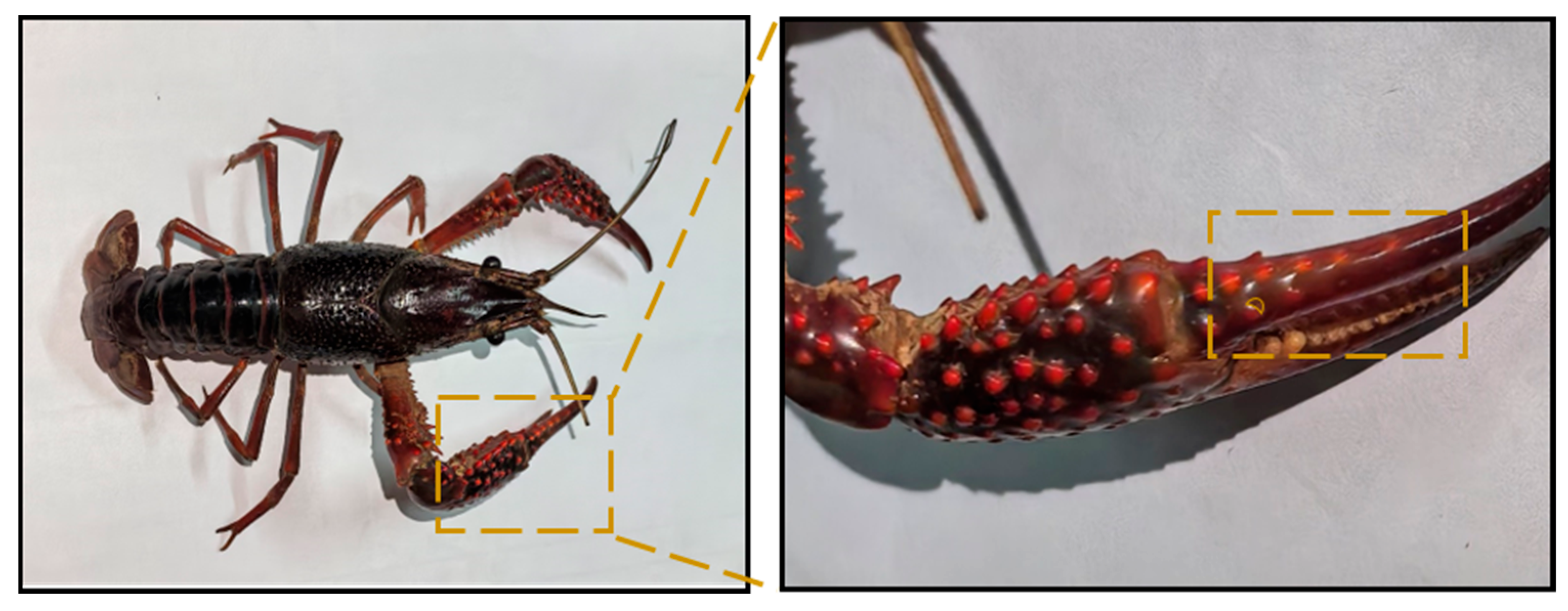
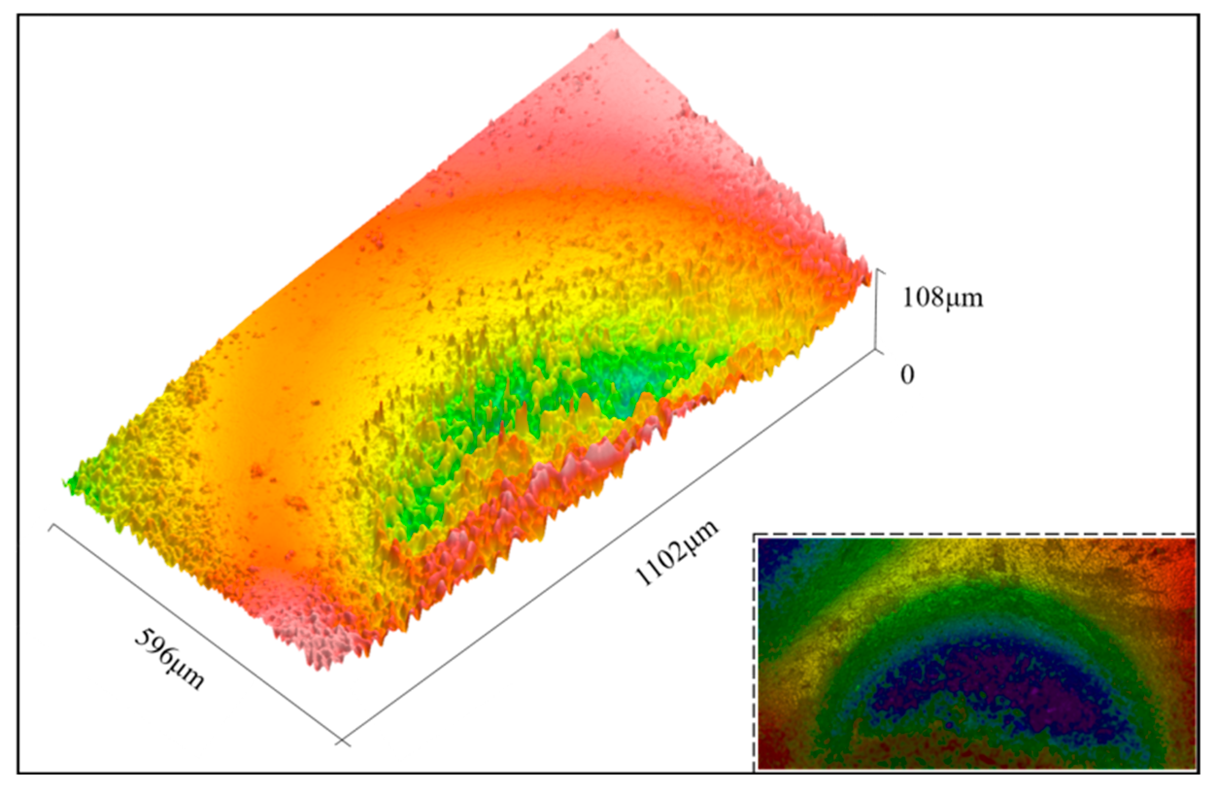
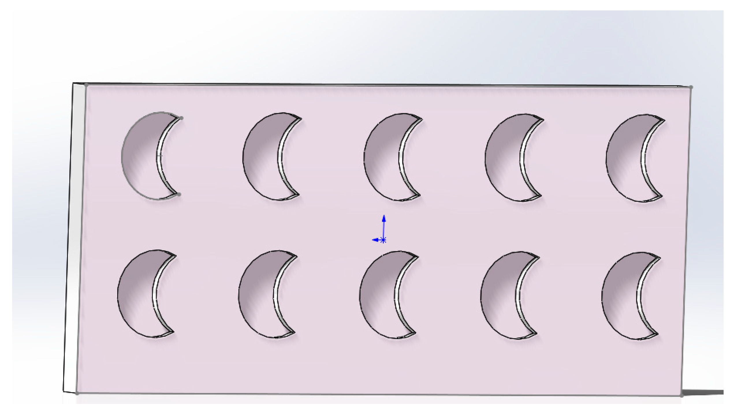
The texture design was biomimetically inspired by the crescent-shaped dimples observed on the exoskeleton of Procambarus clarkii (Figure 1). To quantify the natural dimple morphology, white light interferometry was employed, revealing a maximum depth of approximately 100 μm and an aspect ratio of 2:1 (Figure 2). Based on these biomimetic measurements, scaled crescent-shaped dimples with a length of 100 μm and a width of 50 μm were engineered for surface texturing. The schematic diagram in Figure 3 illustrates the main geometric parameters, where the longitudinal spacing between dimple rows was fixed at 200 μm, while the transverse spacing (a) and depth (h) were designated as variable parameters for systematic optimization.
Femtosecond laser texturing was performed using a Yb:KGW laser (Light Conversion, Pharos) with a wavelength of 1030 nm, a pulse duration of 290 fs, a repetition rate of 100 kHz, and an average power of 5 W. The scanning speed was set to 2000 mm/s, and the number of passes was adjusted to achieve the target texture depths (25–150 μm).

2.3. Preparation of PTFE/PDMS/TiO2 Composite Coating

2.3.1. Hydrophobic Modification of TiO2 Nanoparticles

Hydrophilic rutile TiO2 nanoparticles with approximate diameter of 30 nm were rendered hydrophobic via silanization [19]. Octyltriethoxysilane was dissolved in absolute ethanol and hydrolyzed at 40 °C for 2 h. TiO2 nanoparticles were then added with an OTES to TiO2 mass ratio of 1:3, and the mixture was stirred for 3 h at 40 °C. The suspension was dried at 150 °C for 3 h to obtain hydrophobic TiO2 powder [19,20].

2.3.2. Coating Formulation and Deposition

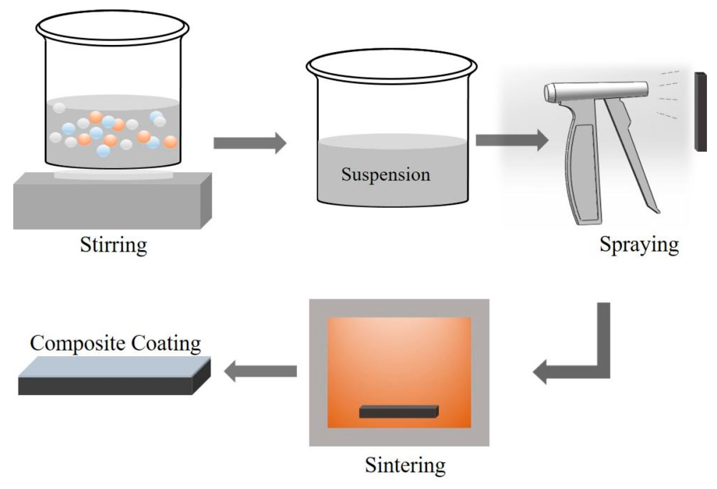
The coating solution was prepared by mixing PTFE emulsion, PDMS, and the modified TiO2 powder in ethyl acetate solvent. A fixed mass ratio of 1:1 was maintained for PTFE to PDMS. A PDMS curing agent was added at a standard ratio of 10:1 relative to the PDMS mass. This mixture was stirred at 1000 rpm for one hour to ensure homogeneity, followed by a five-minute ultrasonication step to break up any residual agglomerates. The complete coating preparation workflow, from TiO2 hydrophobization to spray deposition and curing, is summarized in Figure 4.
Prior to coating application, all substrates underwent a sandblasting pretreatment using 60-mesh brown alumina at a pressure of 4.2 MPa for 100 s to enhance surface roughness and coating adhesion. The coating was then deposited using a controlled air spray process. The spray gun was maintained at a distance of 150 mm from the substrate surface, with an air pressure of 0.2 MPa. The coating thickness was precisely controlled by adjusting the number of spray passes and was monitored in real-time using a handheld coating thickness gauge.

2.3.3. Curing Process

The coated samples were transferred to a drying oven and cured at 300 °C for three hours to promote cross-linking and achieve a robust, adherent film.

2.4. Characterization and Performance Evaluation

2.4.1. Surface Morphology and Structure

Surface morphology was examined by field emission scanning electron microscopy operating at an acceleration voltage of 20 kV. Prior to imaging, all samples were sputter-coated with a thin layer of gold using a magnetron sputtering device to ensure adequate electrical conductivity.

2.4.2. Wettability Assessment

Surface wettability was assessed by measuring the static water contact angle using a standard optical goniometer at room temperature. A 3 μL droplet of deionized water was gently dispensed onto the sample surface from a precision syringe. The contact angle was calculated using the sessile drop method by the instrument’s software. The reported value for each sample represents the average of five independent measurements taken at different locations on the surface [21,22].

2.4.3. Tribological Property Evaluation

Tribological properties were evaluated through dry sliding tests on a high-precision ball-on-disk tribometer at room temperature with an ambient relative humidity of approximately 45%. A commercially available GCr15 bearing steel ball served as the counterface material [23,24]. Tests were conducted under a constant normal load of 20 N, a rotational speed of 150 rpm, and a total test duration of 40 min. The friction coefficient was recorded in real-time by the instrument’s data acquisition system. Wear mass loss was determined as the primary quantitative wear metric by weighing the samples before and after testing using a precision electronic analytical balance with a resolution of 0.1 mg [25]. Each sample was cleaned ultrasonically in ethanol and dried before weighing to remove any loose wear debris.

2.5. Finite Element Analysis

Finite element analysis was performed using Abaqus software (Abaqus/CAE 2025) to simulate dry sliding contact conditions. A three-dimensional model was constructed, consisting of a cylindrical pin representing the counterface ball sliding over a textured plate. To align with the experimental conditions, the pin was assigned material properties equivalent to GCr15 steel with a Young’s modulus of 210 GPa and a Poisson’s ratio of 0.3, while the plate represented 65Mn steel with a Young’s modulus of 211 GPa and a Poisson’s ratio of 0.288. A normal load of 20 N was applied, and the pin was given a sliding displacement of 2 mm. The equivalent von Mises stress distribution on the plate surface was analyzed for varying texture depths ranging from 25 to 150 μm and texture spacings from 100 to 600 μm [6,11].
It is important to note that the primary objective of this finite element analysis is to provide a qualitative understanding of the stress distribution trends influenced by texture geometry. The model is intended to reveal comparative insights and underlying mechanisms rather than to serve as a precise quantitative prediction of the absolute contact stresses under real experimental conditions. This qualitative approach is sufficient to guide the parameter selection and interpret the subsequent tribological behavior.

2.6. Experimental Design and Optimization

The optimization process was conducted in two distinct stages. Initial single-factor experiments were performed to establish the effective working ranges for the four key parameters: texture depth from 25 to 150 μm, texture spacing from 100 to 600 μm, TiO2 mass fraction from 3 to 11 percent, and coating thickness from 10 to 90 μm. Subsequently, a four-factor, five-level Central Composite Rotatable Design (CCD) was employed for systematic optimization. The design comprised a total of 36 experimental runs. The selected responses were contact angle and wear mass loss [26]. Experimental data were analyzed using specialized software to perform analysis of variance, develop quadratic regression models, generate response surfaces, and execute multi-objective numerical optimization.

3. Results and Discussion

3.1. Morphological Characterization

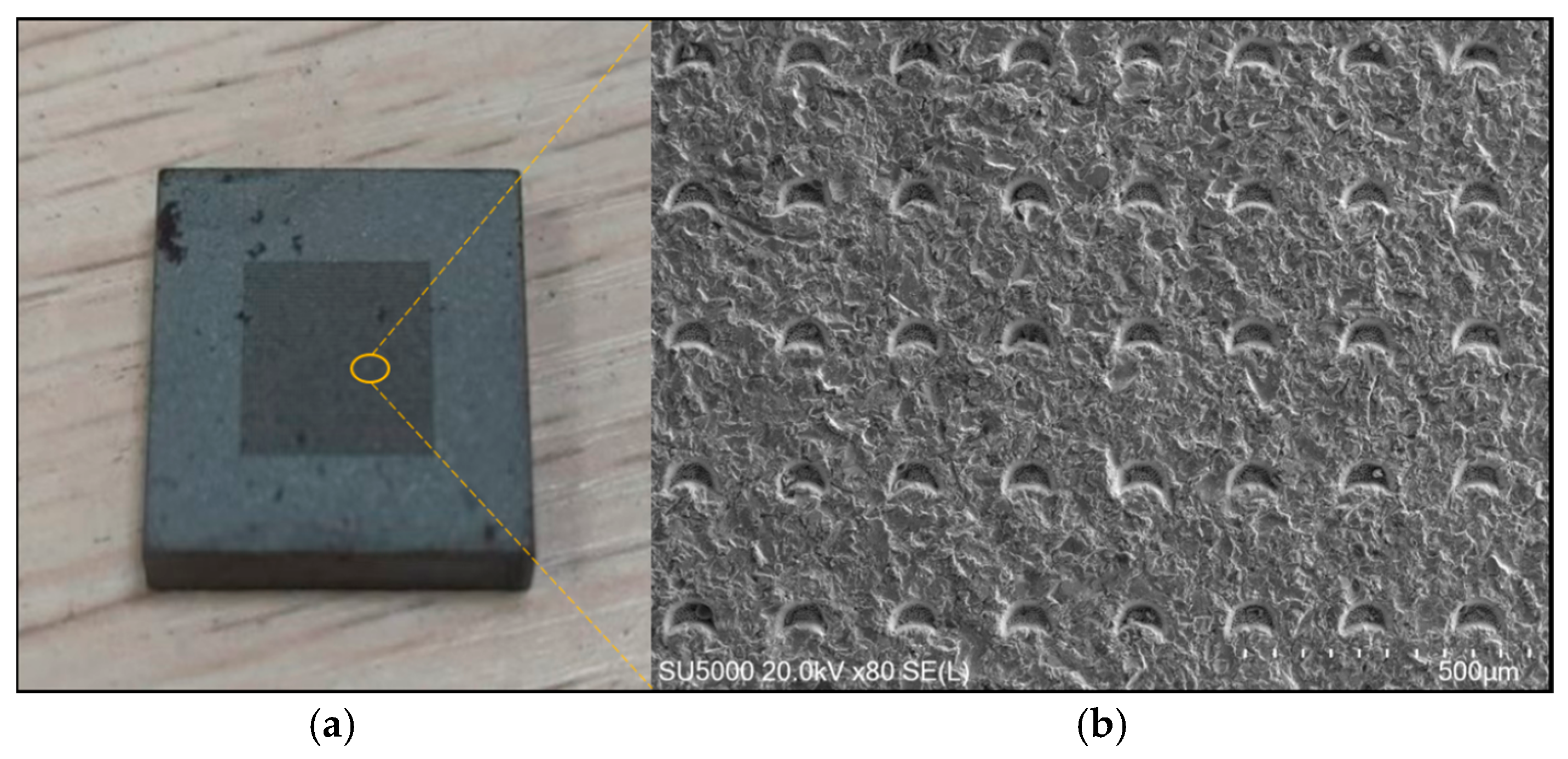
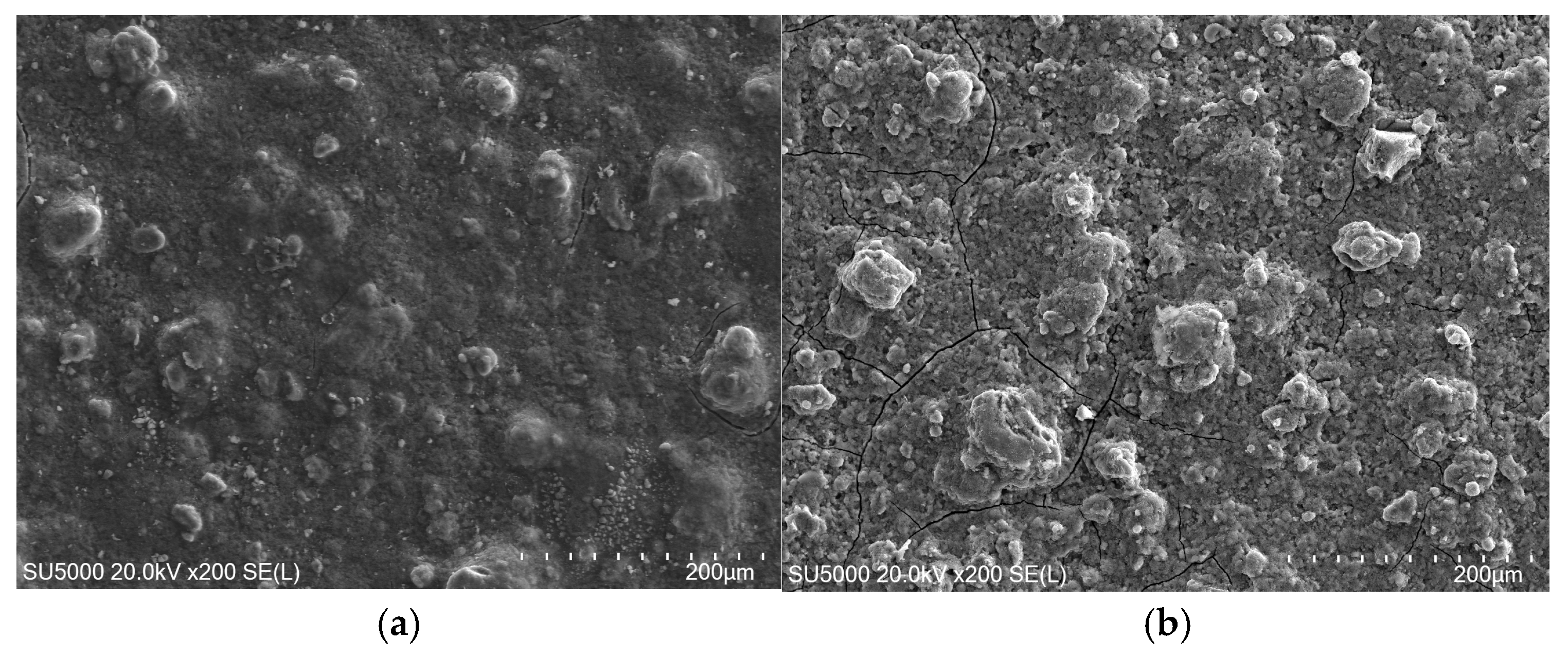
Figure 5a shows a defined array of crescent-shaped micro-dimples fabricated via femtosecond laser ablation on the 65Mn steel surface. The array exhibits high uniformity and precise arrangement according to the CAD design. Figure 5b presents a higher magnification SEM image of a single crescent-shaped dimple, revealing sharp edges and minimal evidence of a heat-affected zone or recast layer. This clean ablation morphology is characteristic of ultrafast laser processing [27], where the ultrashort pulse duration minimizes thermal diffusion and material damage. The composite coating uniformly covers the textured substrate, conforming to the underlying topography. At low magnification (Figure 6a), the coating shows coverage without cracks or delamination. Higher magnification in Figure 6b reveals a hierarchical microstructure comprising a porous PTFE/PDMS matrix decorated with micro-scale agglomerates of TiO2 nanoparticles. These agglomerates are induced by the PDMS binder during the curing process. This specific micro–nano dual-scale roughness is an important factor for achieving stable superhydrophobicity, as it facilitates the entrapment of air pockets according to the Cassie–Baxter wetting model [28,29].
Notably, Figure 6b reveals some micro-cracks on the coating surface. These cracks may originate from the relief of internal stresses during the curing process at 300 °C, especially with higher TiO2 content. According to previous studies [30], Si from PDMS contributes to the formation of a stable siloxane network, enhancing hydrophobicity and thermal stability. However, excessive TiO2 agglomeration may increase local stress, promoting crack formation. Despite these micro-cracks, the coating remained adherent and did not delaminate during wear tests, indicating that the PTFE/PDMS matrix provides sufficient toughness to accommodate minor cracking.
Although EDS analysis and XRD characterization were not performed in this study, the composition and structural features of the coating can be reasonably inferred from the preparation process and existing literature. The coating was prepared through a combination of mechanical stirring (1000 rpm for 1 h) and ultrasonication (5 min), which helps to ensure homogeneous dispersion of TiO2 nanoparticles within the PTFE/PDMS matrix. The SEM images (Figure 6) clearly show the presence of TiO2 agglomerates uniformly distributed across the surface, suggesting good dispersion. Previous studies on similar PTFE/PDMS/TiO2 composite coatings have confirmed that such preparation methods yield uniform elemental distribution and consistent coating properties [19,31]. Furthermore, the observed superhydrophobicity (contact angle > 150°) and enhanced wear resistance indirectly support the successful incorporation and functional performance of the coating components. Future work will include detailed chemical and phase analyses to further validate the coating structure.

3.2. Effect of Texture Parameters on Dry Contact and Wettability

Finite element analysis results illustrate the role of textures in modifying contact mechanics. The non-textured surface exhibits a classic Hertzian contact stress field with a maximum von Mises stress of 89.1 MPa and noticeable stress concentration at the trailing edge of the contact path. Textured surfaces help to redistribute this stress. For a fixed spacing of 100 μm, increasing the texture depth from 25 to 100 μm leads to a more uniform stress distribution but concurrently raises the peak stress due to the corresponding reduction in load-bearing area. Crucially, however, the severe stress concentration observed on the smooth surface is effectively mitigated. For a fixed depth of 50 μm, increasing the texture spacing from 100 to 600 μm reduces the peak stress but enlarges the areas of localized stress concentration between individual textures. The analysis suggests that textures with depths below 100 μm and spacings below 400 μm offer an optimal compromise between maintaining adequate load-bearing capacity and achieving beneficial stress homogenization.
The friction and wear performances of uncoated textured surfaces show certain trends. Wear mass loss as a function of texture depth with spacing fixed at 200 μm shows a distinct minimum at a depth of 75 μm. Shallower textures demonstrate limited debris-trapping ability, while deeper textures create sharp edges that act as stress concentrators, paradoxically increasing material removal despite their greater volume. This trend shows some correlation with the stress distribution patterns predicted by finite element analysis. The corresponding steady-state friction coefficients show that textures with depths of 50, 75, and 100 μm achieve lower and more stable friction compared to the non-textured reference surface, confirming their beneficial role in friction reduction.
For surfaces with a fixed texture depth of 75 μm, wear loss reaches a minimum at a spacing of 200 μm. Smaller spacings increase the effective surface roughness and contact stress, leading to elevated wear. Conversely, larger spacings significantly reduce the debris-trapping capability of the surface and allow substantial stress concentration to develop on the intervening smooth areas, also resulting in increased wear. The friction coefficient follows a similar trend, with spacings between 200 and 300 μm providing the most favorable friction characteristics.
Wettability measurements provide further insight into surface behavior. The polished 65 Mn steel surface is inherently hydrophilic, exhibiting a contact angle of approximately 67 degrees. The influence of texture depth and spacing on the wettability and wear performance of uncoated surfaces is systematically summarized in Table 1. Introducing textures significantly reduces the contact angle to a range between 40 and 58 degrees, thereby increasing surface hydrophilicity. This observation is consistent with the Wenzel wetting model for an initially hydrophilic material [21]. However, a slight but measurable recovery in contact angle is observed for both the deepest texture of 150 μm and the largest spacing of 600 μm. This phenomenon suggests that under specific geometric conditions, the textures can begin to entrap air at the solid–liquid interface, initiating a transition toward a composite solid–air–liquid interface [28].

3.3. Effect of Coating Parameters on Hydrophobicity and Wear Resistance

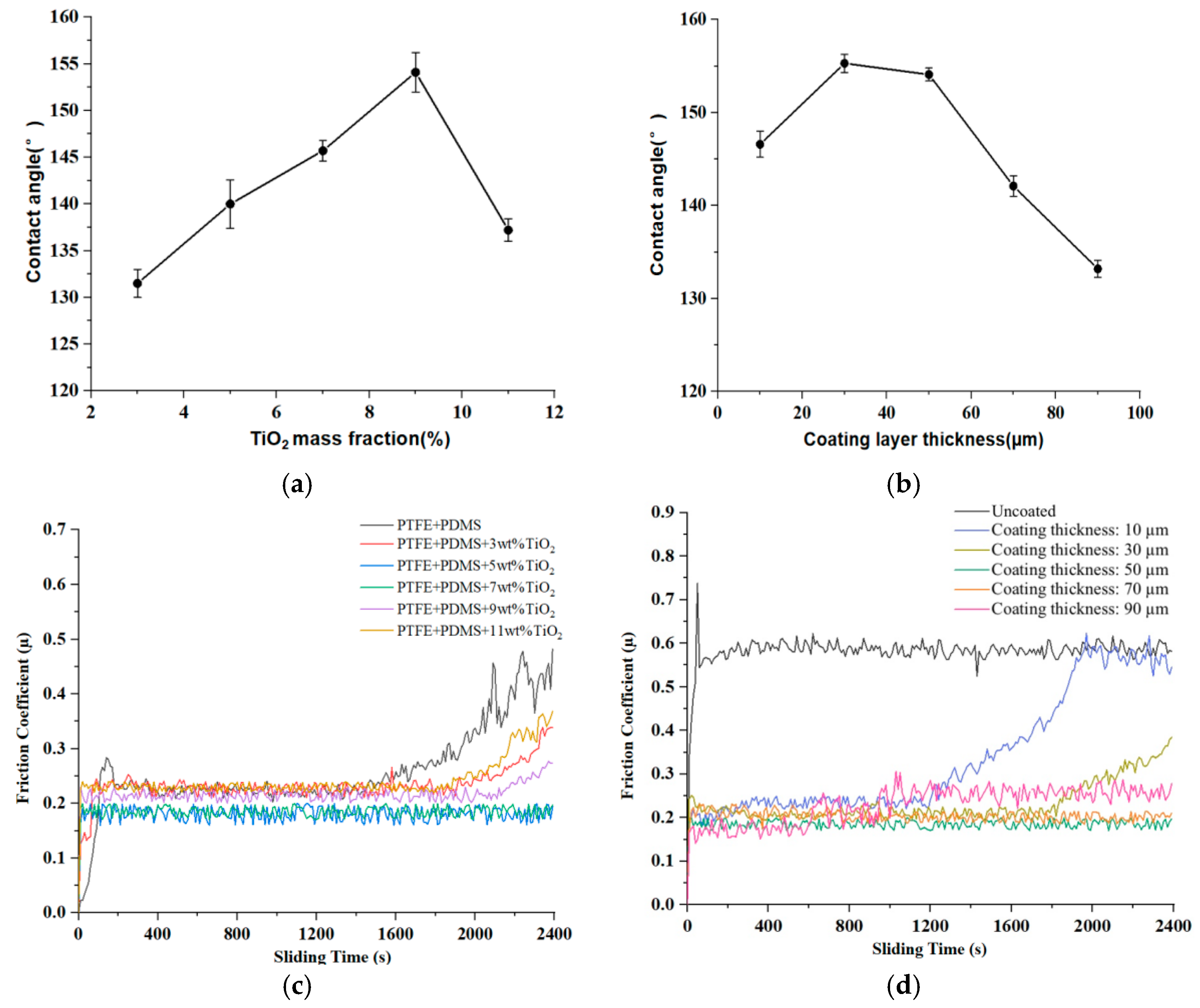
The individual effects of TiO2 mass fraction and coating thickness on the performance of the PTFE/PDMS/TiO2 nanocomposite coating suggest optimization trends, as shown in Figure 7 and summarized in Table 2. Figure 7a shows the static water contact angle increasing steadily with TiO2 content, reaching a maximum of 154.1° at 9 wt%, classifying the surface as superhydrophobic. Beyond this point, the contact angle decreases to 137.2° at 11 wt% TiO2. This enhancement is attributed to increased surface roughness from TiO2 nanoparticle agglomerates promoting air entrapment [29,30]. However, excessive TiO2 loading can lead to non-uniform particle distribution and reduce the effective exposure of the underlying low-surface-energy matrix, degrading hydrophobic performance.
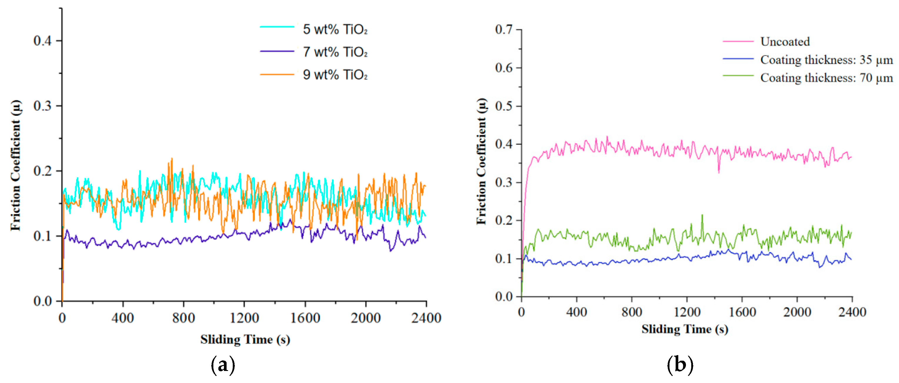
The evolution of the friction coefficient in Figure 7c provides complementary insight. Coatings with 5 and 7 wt% TiO2 exhibit the lowest and most stable friction coefficients below 0.20 over the entire test, suggesting optimal wear resistance. In contrast, coatings with 3 or 11 wt% TiO2 show a premature increase in friction after approximately 1800–2000 s, signaling earlier coating failure.
The relationship between coating thickness and performance also shows an optimum. The contact angle reaches a maximum of 155.3° at 30 μm thickness (Figure 7b). Very thin coatings may not fully cover the substrate’s roughness, while very thick coatings can develop micro-cracks and internal stresses during curing, degrading surface quality. Friction coefficient analysis in Figure 7d reveals that a 50 μm thickness provides the best durability, maintaining a stable friction coefficient around 0.18 throughout the wear test.
The comprehensive effects of coating parameters on hydrophobicity and wear resistance are summarized in Table 2.

3.4. Systematic Optimization via Response Surface Methodology and Synergistic Analysis

Based on the preliminary parameter windows identified through single-factor experiments, a four-factor, five-level Central Composite Rotatable Design (CCD) was employed for systematic optimization. The coded and actual levels of the factors are listed in Table 3.
The design matrix comprising 36 experimental runs and the corresponding experimental results for contact angle and wear mass loss are presented in Table 4.
The analysis of variance for the fitted quadratic models is presented in Table 5. Both models for contact angle and wear mass loss are statistically highly significant, as indicated by probability values less than 0.0001 and substantial F-values. The lack-of-fit tests are not significant, confirming the models’ adequacy in representing the experimental data. High coefficients of determination, 0.9465 for contact angle and 0.9790 for wear loss, along with adequate precision ratios well above 4, collectively indicate excellent model fit and sufficient signal strength for effective navigation of the design space.
The final empirical models in terms of coded factors are given in Equations (1) and (2). Only significant terms (p < 0.05) are retained.
Y 1 = 150.12 3.05 X 1 1.07 X 2 + 2.35 X 3 + 1.51 X 4 1.60 X 1 X 3 1.63 X 1 X 4 + 1.41 X 3 X 4 1.75 X 2 2 7.44 X 3 2 2.45 X 4 2
Y 2 = 7.07 + 0.85 X 1 + 0.67 X 2 + 0.38 X 3 3.70 X 4 1.62 X 1 X 2 + 1.16 X 1 X 3 0.93 X 1 X 4 + 2.73 X 2 X 3 1.31 X 3 X 4 + 2.29 X 1 2 + 2.34 X 2 2 + 1.60 X 3 2 + 2.46 X 4 2
In these equations, Contact Angle represents the response in degrees, Wear Loss represents the response in milligrams, and the variables w, t, h, and a are the coded values of TiO2 mass fraction, coating thickness, texture depth, and texture spacing, respectively.
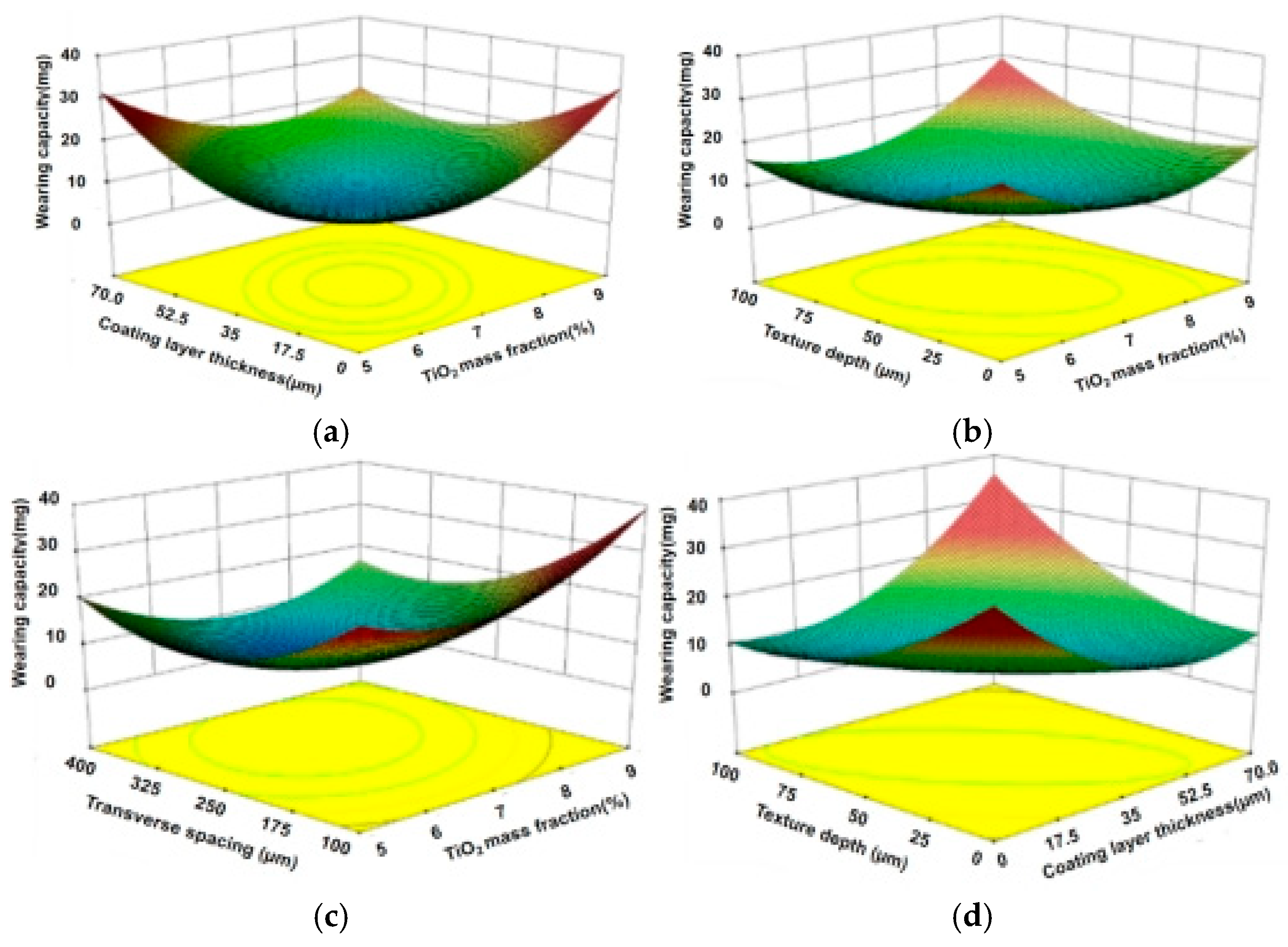
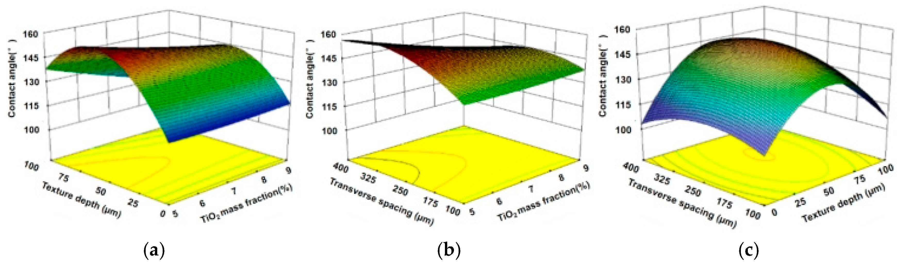
Analysis of variance (ANOVA) confirmed that the derived second-order regression models for both contact angle and wear loss were highly significant (p < 0.01), as detailed in Table 4. The lack-of-fit tests were non-significant (p > 0.05), validating the model adequacy for predictive analysis and optimization. The nature of the factor interactions was then elucidated through response surface analysis, such as the interactive effects of texture depth and TiO2 fraction on contact angle (Figure 8), and on wear loss (Figure 9). Key insights revealed that an optimal texture depth was critical for effective debris entrapment while mitigating stress concentration. Similarly, a moderate TiO2 mass fraction was essential for enhancing hardness and constructing micro-roughness without provoking detrimental agglomeration.
The multi-objective optimization goal was formulated to maximize hydrophobicity and minimize wear, defined by the following objective function and constraints:
{ m a x Y 1 ( X 1 , X 2 , X 3 , X 4 ) m i n Y 2 ( X 1 , X 2 , X 3 , X 4 ) s . t . { 2 X 1 2 2 X 2 2 2 X 3 2 2 X 4 2 }
Response surface analysis of these models provided deep insights into the factor interactions governing the surface’s performance. The interaction between texture depth (X3) and TiO2 mass fraction (X1) on the contact angle (Figure 8) revealed that a moderate TiO2 fraction coupled with an intermediate texture depth maximizes hydrophobicity. This is likely attributable to the formation of an optimal micro–nano hierarchical roughness, where the textures provide the micro-scale structure and the TiO2 aggregates contribute to the nano-scale roughness, synergistically enhancing air entrapment. Conversely, the interaction between texture lateral spacing (X4) and TiO2 mass fraction (X1) on wear loss (Figure 9) demonstrated that a smaller spacing and a medium TiO2 content were critical for minimizing wear. This underscores the importance of a higher texture density for effective debris entrapment, thereby mitigating three-body abrasion, while an excessive TiO2 content may lead to brittle agglomerates that compromise the coating’s cohesive strength. The numerical optimization function, constrained to maximize Y1 and minimize Y2, converged on the global optimum used for prototype fabrication: 6% TiO2, 40 μm coating thickness, 50 μm texture depth, and 250 μm texture spacing.
To validate the predictive models, three replicate experiments were conducted precisely at the optimal parameter settings. The average results were a contact angle of 150.8 degrees with a standard deviation of 2.5 degrees, and a wear mass loss of 9.3 milligrams with a standard deviation of 0.8 milligrams. The excellent agreement between these experimental values and the model predictions, with relative errors of less than 0.9 percent for contact angle and 4.5 percent for wear loss, robustly confirms the reliability and accuracy of the developed response surface methodology models.
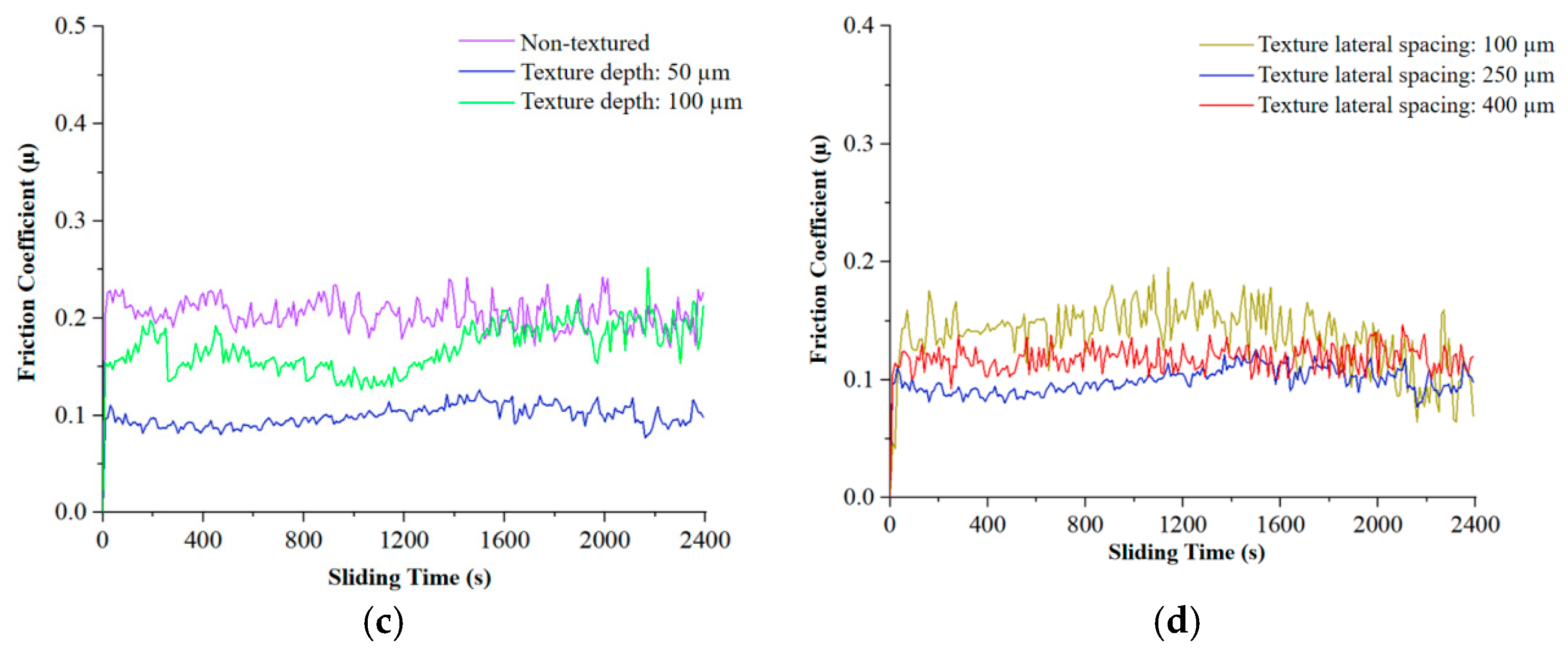
Figure 10 provides strong inferential evidence suggesting a synergistic effect through friction coefficient curves for samples prepared under key conditions. As shown in Figure 10a, the sample prepared with the optimal combination of texture and coating exhibits the lowest and most stable friction coefficient, averaging approximately 0.10 throughout the test. Figure 10b shows the coating-only sample, prepared with the same optimal TiO2 content and coating thickness but on a non-textured substrate, which displays a higher and slightly less stable friction coefficient around 0.18. The textured-only sample (Figure 10c), featuring the optimal texture geometry but without any coating, displays a much higher and significantly more variable friction coefficient around 0.35. Finally, Figure 10d presents the untreated bare substrate, which performs the worst. This clear performance hierarchy strongly implies a synergistic interaction: the functional coating drastically reduces interfacial shear stress and adhesion, while the underlying texture stabilizes the tribological interface by efficiently managing third-body particles and preventing coating plowing. Their combination yields a performance level that surpasses what would be expected from the simple additive contribution of each technology applied independently.
Although direct SEM/EDS of wear tracks was not performed, the synergistic effect can be inferred from the friction curves (Figure 10). The optimized textured coating surface exhibited the lowest and most stable friction coefficient (~0.10), significantly lower than that of the coating-only (~0.18) and texture-only (~0.35) surfaces. This indicates that the textures effectively trap wear debris, preventing three-body abrasion, while the coating provides a low-shear interface. Similar synergistic mechanisms have been reported in previous studies [11,32], supporting our interpretation.
The proposed synergistic mechanism is illustrated conceptually. The bionic surface textures function through multiple complementary mechanisms: they act as efficient debris reservoirs, capturing generated wear particles and preventing them from participating in destructive three-body abrasive wear; they serve as stress distributors, mitigating localized stress peaks that could otherwise initiate coating delamination or substrate fatigue; and they physically reduce adhesion by disrupting the continuity of the solid–solid or solid–liquid contact interface. Concurrently, the PTFE/PDMS/TiO2 nanocomposite coating contributes by providing an ultra-low surface energy top layer that enables high hydrophobicity and minimizes adhesive forces; by hardening the immediate surface through well-dispersed TiO2 nanoparticles, thereby increasing resistance to abrasive penetration and cutting; and by facilitating a beneficial rolling–sliding contact mode via the nano-particles, which further reduces the effective friction coefficient. Importantly, the textured substrate also enhances the mechanical adhesion of the coating through interlocking, creating a durable and integrated multifunctional surface system.
The wear resistance of the coating is further enhanced by the incorporation of TiO2 nanoparticles. As suggested by [33], TiO2 can act as a physical barrier and create a tortuous path for corrosive media, thereby improving the durability of the coating. In dry sliding conditions, the nanoparticles reduce direct contact area and promote a rolling–sliding mode, lowering friction and wear. This mechanism is consistent with our observations where optimal TiO2 content (6%) yielded the lowest wear loss.
It should be noted that static contact angle alone is insufficient to fully characterize superhydrophobicity; dynamic parameters such as contact angle hysteresis and sliding angle are also important. However, a static angle above 150° is a strong indicator of superhydrophobic behavior [29], and our optimized surface achieves this value. Future work will include dynamic wetting measurements to confirm the low-adhesion state.

4. Conclusions

A synergistic surface engineering strategy integrating femtosecond laser-fabricated bionic textures and a PTFE/PDMS/TiO2 nanocomposite coating was successfully developed for 65Mn steel. Finite element analysis confirmed that textures with depths below 100 μm and spacings below 400 μm effectively homogenize surface stress distribution under dry sliding contact.
Single-factor experiments established effective preliminary parameter windows: texture depth between 50 and 100 μm, texture spacing between 100 and 400 μm, TiO2 mass fraction between 5 and 9 percent, and coating thickness between 30 and 70 μm.
Response surface methodology-based optimization revealed distinct influence patterns: contact angle was predominantly influenced by TiO2 content and texture depth, while wear mass loss was primarily influenced by texture spacing. Significant interactions between coating composition parameters and texture geometry parameters were quantitatively identified and analyzed.
The optimal parameter combination was determined to be a TiO2 mass fraction of 6%, a coating thickness of 40 μm, a texture depth of 50 μm, and a texture spacing of 250 μm. The surface engineered with these parameters achieved a superhydrophobic contact angle of 150.8° and a wear mass loss of 9.3 mg under standard dry sliding test conditions against a GCr15 steel ball with a 20 N load and 150 rpm speed for 40 min. This represents a balanced and superior multifunctional performance that markedly exceeds that of the bare substrate, textured-only, and coating-only samples.
The performance enhancement is attributed to a clear synergistic mechanism where the surface textures actively manage debris and redistribute contact stress to protect the functional coating, while the coating itself provides a low-surface-energy, hardened top layer that simultaneously minimizes interfacial adhesion and resists abrasive wear. This work provides a systematic and optimized framework for the rational design of advanced multifunctional surfaces suitable for demanding tribological applications across various engineering fields.
In summary, this study demonstrates that the combination of bionic laser texturing and a PTFE/PDMS/TiO2 nanocomposite coating can effectively enhance both the hydrophobicity and wear resistance of 65Mn steel. While these results are promising, several aspects warrant further investigation. First, although mass loss provided a reliable comparative measure of wear resistance (correlating well with friction trends), future studies should include three-dimensional profilometry for volumetric wear analysis and wear track morphology observation to gain deeper insight into wear mechanisms. Second, the superhydrophobic state was inferred from static contact angles >150°; dynamic wetting parameters such as contact angle hysteresis and sliding angle would further confirm the low-adhesion behavior. Third, the robustness of the coating was indirectly supported by the absence of delamination during wear tests and by the known properties of its constituents (PTFE, PDMS, TiO2) [34,35]; however, direct evidence from adhesion tests (e.g., scratch or pull-off) and chemical/thermal analyses (FTIR, XPS, DSC, TGA) would provide a more comprehensive understanding of coating performance. Addressing these aspects in future work will help validate and extend the findings of this study.

Author Contributions

Conceptualization, H.C.; Methodology, H.C. and R.L.; Software, Z.G.; Validation, Z.L. and X.W.; Formal Analysis, Z.G., Z.Z. and Y.W.; Investigation, Z.L.; Resources, Y.Z.; Data Curation, Z.Z. and Y.W.; Writing—Original Draft Preparation, Z.L.; Writing—Review & Editing, H.C. and Y.Z.; Visualization, Z.G., X.W. and Z.L.; Supervision, H.C.; Project Administration, Y.Z.; Funding Acquisition, H.C. All authors have read and agreed to the published version of the manuscript.

Funding

The study was financially supported by the National Key Research and Development Program of China (Grant No. 2021YFD2000401).

Institutional Review Board Statement

The bionic design was inspired solely by the morphological observation of biological structures, and all experiments were conducted on material specimens (65Mn steel) and coatings.

Informed Consent Statement

Informed consent was obtained from all subjects involved in the study.

Data Availability Statement

Data Availability Statement The data that support the findings of this study will be available in the figshare repository upon publication of this article. The data are available from the corresponding author, H.C., upon reasonable request until then.

Conflicts of Interest

The authors declare no conflicts of interest. The funders had no role in the design of the study; in the collection, analyses, or interpretation of data; in the writing of the manuscript; or in the decision to publish the results.

Abbreviations

The following abbreviations are used in this manuscript:
PTFEPolytetrafluoroethylene
PDMSPolydimethylsiloxane
TiO2Titanium Dioxide
RSMResponse Surface Methodology
SEMScanning Electron Microscope
FEAFinite Element Analysis
ANOVAAnalysis of Variance
CCDCentral Composite Rotatable Design

References

  1. Wang, L.Y.; Liao, J.Y.; Hu, H.; Liu, L.; Bai, X.; Chen, C.-L. Research status and prospects of anti-adhesion and detachment technologies for soil-engaging components of agricultural machinery. J. Chin. Agric. Mech. 2021, 42, 214–221. [Google Scholar] [CrossRef] [Scilit]
  2. Ren, L.Q.; Chen, D.X.; Chen, B.C. Overview of soil adhesion research. Trans. Chin. Soc. Agric. Eng. 1990, 1, 1–7. [Google Scholar]
  3. Chen, Y.S. Fundamentals of Tribology; Beihang University Press: Beijing, China, 1991. [Google Scholar]
  4. Bhushan, B. Introduction to Tribology; John Wiley & Sons: New York, NY, USA, 2002. [Google Scholar]
  5. Bhushan, B. Principles and Applications of Tribology, 2nd ed.; John Wiley & Sons: Hoboken, NJ, USA, 2013. [Google Scholar]
  6. Popov, V.L. Contact Mechanics and Friction: Physical Principles and Applications; Springer: Berlin, Germany, 2010. [Google Scholar]
  7. Bowden, F.P.; Tabor, D. The Friction and Lubrication of Solids; Revised edition; Clarendon Press: Oxford, UK, 1964. [Google Scholar]
  8. Kragelsky, I.V. Principles of Friction and Wear Calculations; Mechanical Industry Press: Beijing, China, 1982. [Google Scholar]
  9. Jia, H.L.; Wang, W.P.; Chen, Z.; Zheng, T.; Zhang, P.; Zhuang, J. Research status and prospects of optimization for soil-engaging components of agricultural machinery. Trans. Chin. Soc. Agric. Mach. 2017, 48, 1–13. [Google Scholar]
  10. Fision, I. State of the art in laser surface texturing. J. Tribol. 2005, 127, 248–253. [Google Scholar] [CrossRef] [Scilit]
  11. Gachot, C.; Rosenkranz, A.; Hsu, S.M.; Costa, H.L. A critical assessment of surface texturing for friction and wear improvement. Wear 2017, 372–373, 21–41. [Google Scholar] [CrossRef] [Scilit]
  12. Massah, J.; Rahmani Fard, M.; Aghel, H. An optimized bionic electro-osmotic soil-engaging implement for soil adhesion reduction. J. Terramech. 2021, 95, 1–6. [Google Scholar] [CrossRef] [Scilit]
  13. Wang, Y.; Xue, W.; Ma, Y.; Tong, J.; Liu, X.; Sun, J. DEM and soil bin study on a biomimetic disc furrow opener. Comput. Electron. Agric. 2019, 156, 209–216. [Google Scholar] [CrossRef] [Scilit]
  14. Puoza, C.J. Research progress of surface texturing and thermal diffusion technology to improve tribological properties of materials. Prog. Eng. Sci. 2025, 2, 100034. [Google Scholar] [CrossRef] [Scilit]
  15. Holmberg, K.; Matthews, A. Coatings Tribology: Properties, Mechanisms, Techniques and Applications in Surface Engineering, 2nd ed.; Elsevier: Amsterdam, The Netherlands, 2009. [Google Scholar]
  16. Yang, S.; Liu, Z.; Zhang, S.; Wang, W.; Huang, G.; Lu, L.; Xie, Y. Self-lubricating film formation and ultra-low wear of PTFE/aluminum through anodization induced nano-microtextures. Tribol. Int. 2025, 208, 110657. [Google Scholar] [CrossRef] [Scilit]
  17. Voevdin, A.A.; Zabinski, J.S. Nanocomposite and nanostructured tribological materials for space applications. Compos. Sci. Technol. 2005, 65, 741–748. [Google Scholar] [CrossRef] [Scilit]
  18. Yuan, Y.; Louhichi, B.; Heidarshenas, B.; Alrasheedi, N.H.; Bal, B.; Hussain, G. Functional surfaces of the future: Integrating texturing and coatings for superior performance. Mater. Today Chem. 2025, 48, 103017. [Google Scholar] [CrossRef] [Scilit]
  19. Zhou, X.; Yu, S.; Guan, S.; Lv, Z.; Liu, E.; Zhao, Y. Fabrication and characterization of superhydrophobic TiO2 nanotube coating by a facile anodic oxidation approach. Surf. Coat. Technol. 2018, 354, 83–91. [Google Scholar] [CrossRef] [Scilit]
  20. Li, J.W.; Gu, T.L.; Li, X.Y.; Wang, Z.; Hu, B.; Ma, Y. Analysis and experiment on bionic drag reduction characteristics of potato digger under heavy black soil conditions. Trans. Chin. Soc. Agric. Eng. 2023, 39, 1–9. [Google Scholar]
  21. Wenzel, R.N. Resistance of solid surfaces to wetting by water. Ind. Eng. Chem. 1936, 28, 988–994. [Google Scholar] [CrossRef] [Scilit]
  22. Erbil, H.Y. The debate on the dependence of apparent contact angles on drop contact area or three-phase contact line: A review. Surf. Sci. Rep. 2014, 69, 325–365. [Google Scholar] [CrossRef] [Scilit]
  23. Yuan, Z.; Jiang, Z.; Zhou, Z.; Wang, H.; Li, J.; Cai, Z.; Xing, Z.; Ding, C.; Piao, Z. Effect of surface roughness on friction and wear behavior of GCr15 bearing steel under different loads. Surf. Sci. Technol. 2024, 2, 28. [Google Scholar] [CrossRef] [Scilit]
  24. Liu, H.; Chen, Y.; Wang, X.; Guo, Y.; Xue, W.; Li, D.; Chen, X.-Q. Correlating numerical modelling with experimental studies to quantify the wear resistance of high-carbon chromium bearing steel in mixed lubrication. Tribol. Int. 2023, 188, 108819. [Google Scholar] [CrossRef] [Scilit]
  25. Stachowiak, G.W.; Batchelor, A.W. Engineering Tribology, 4th ed.; Butterworth-Heinemann: Waltham, MA, USA, 2013. [Google Scholar]
  26. Venkataramanan, A.R.; Madheswaran, S.; Lakshamana, S.K.; Jawahar, R.R.; Prabhu, L. Application of CCD in RSM to obtain optimize treatment of tribological characteristics of WC-10Co-4Cr nanoceramic thermal spray coating. Mater. Today Proc. 2020, 45, 6160–6170. [Google Scholar] [CrossRef] [Scilit]
  27. Drelich, J.; Chibowski, E.; Meng, D.D.; Terpilowski, K. Hydrophilic and superhydrophilic surfaces and materials. Soft Matter 2011, 7, 9804–9828. [Google Scholar] [CrossRef] [Scilit]
  28. Cassie, A.B.D.; Baxter, S. Wettability of porous surfaces. Trans. Faraday Soc. 1944, 40, 546–551. [Google Scholar] [CrossRef] [Scilit]
  29. Shahzadi, S.; Nadeem, N.; Javid, A.; Nawab, Y.; Zubair, U. Strategic insights into realizing superhydrophobic surfaces on cellulosic substrates through conventional and sustainable technologies. Surf. Interfaces 2024, 53, 105034. [Google Scholar] [CrossRef] [Scilit]
  30. Yan, X.C.; Hu, J.; Zhang, X.; Xu, W. Obtaining superior low-temperature wear resistance in Q&P-processed medium Mn steel with a low initial hardness. Tribol. Int. 2022, 175, 107803. [Google Scholar] [CrossRef] [Scilit]
  31. Peng, J.; Xie, S.H.; Xia, J.H.; Wang, X.X.; Ni, Z.L.; Wang, P.; Chen, N.N. Investigation of Process and Properties of Cu-Mn-Al Alloy Cladding Deposited on 27SiMn Steel via Cold Metal Transfer. Crystals 2025, 15, 858. [Google Scholar] [CrossRef] [Scilit]
  32. Nosonovsky, M.; Bhushan, B. Superhydrophobic surfaces and emerging applications: Non-adhesion, energy, green engineering. Curr. Opin. Colloid Interface Sci. 2009, 14, 270–280. [Google Scholar] [CrossRef] [Scilit]
  33. Hong, Y.; Dong, D.D.; Zou, G.P.; Li, Y.; Lin, S.S.; Kuang, T.C.; Wu, Y.Z.; Dai, M.J. The corrosion response of the heterogeneous nitriding structure originated from the laser additive manufactured steel. Corros. Sci. 2023, 218, 111188. [Google Scholar] [CrossRef] [Scilit]
  34. Alsamhary, K.; Al-Enazi, N.; Khonakdar, H.A. Thermally stable superhydrophobic and antibacterial PDMS/nano-PTFE coatings: A two-step spray method and TiO2-enhanced performance. Colloids Surf. A Physicochem. Eng. Asp. 2026, 731, 139036. [Google Scholar] [CrossRef] [Scilit]
  35. PMC. Tunable, permanent and instantly available super-wettability states on metal surfaces by laser texturing and plasma coating. Sci. Rep. 2025, 15, 27595. [Google Scholar] [CrossRef] [Scilit]
Figure 1. Exoskeletal dimples on the claw of Procambarus clarkii.
Coatings 16 00356 g001
Figure 2. White light interferometry scan of natural dimple morphology.
Coatings 16 00356 g002
Figure 3. Schematic of designed crescent-shaped texture with key dimensions.
Coatings 16 00356 g003
Figure 4. Preparation process of anti-stick and wear-resistant coating.
Coatings 16 00356 g004
Figure 5. (a) Textured 65Mn steel block; (b) SEM image of a single crescent-shaped dimple fabricated by femtosecond laser, demonstrating high dimensional fidelity and minimal heat-affected zone.
Coatings 16 00356 g005
Figure 6. SEM images of PTFE/PDMS/TiO2 composite coating: (a) low magnification, (b) high magnification.
Coatings 16 00356 g006
Figure 7. Single-factor effects: (a) contact angle vs. TiO2 content, (b) contact angle vs. coating thickness, (c) friction coefficient vs. TiO2 content, (d) friction coefficient vs. coating thickness.
Coatings 16 00356 g007
Figure 8. Effects of various factors on contact angle. (a) Effects of texture depth and TiO2 mass fraction on contact angle. (b) Effects of transverse spacing and TiO2 mass fraction on contact angle. (c) Effects of transverse spacing and Texture depth fraction on contact angle.
Coatings 16 00356 g008
Figure 9. Effects of various factors on wear volume. (a) Effects of coating layer thickness and TiO2 mass fraction on wear volume. (b) Effects of texture depth and TiO2 mass fraction thickness on wear volume. (c) Effects of transverse spacing and TiO2 mass fraction thickness on wear volume. (d) Effects of texture depth and coating layer thickness on wear volume.
Coatings 16 00356 g009
Figure 10. Friction coefficient curves for samples under key conditions: (a) optimized textured coating, (b) coating-only on smooth substrate, (c) texture-only without coating, (d) untreated bare substrate.
Coatings 16 00356 g010aCoatings 16 00356 g010b
Table 1. Effect of texture parameters on the wettability and wear performance of uncoated 65Mn steel surfaces.
Texture ParameterLevel (μm)Contact Angle
(°)
Wear Mass Loss
(mg)
Friction Coefficient
(μ)
 Depth (h) (Spacing a = 200 μm) 0 (Polished)67.0 ± 2.10.35
 2556.8 ± 1.817.5 ± 0.80.35
 5049.3 ± 2.014.6 ± 0.40.3
 7544.8 ± 1.712.8 ± 0.50.28
 10043.4 ± 2.415.2 ± 0.50.32
 12545.4 ± 1.919.3 ± 1.10.38
 15046.7 ± 2.319.6 ± 1.10.4
Spacing (a) (Depth h = 75 μm)0 (Polished)67.0 ± 2.10.35
 10040.2 ± 1.513.5 ± 0.60.37
 20044.8 ± 1.712.8 ± 0.50.28
 30048.1 ± 1.913.1 ± 0.80.3
 40051.3 ± 2.214.5 ± 0.90.33
 50055.6 ± 2.017.3 ± 1.10.41
 60058.6 ± 2.516.6 ± 0.80.39
Table 2. Effect of coating parameters on the hydrophobicity and wear performance of coated (non-textured) 65Mn steel surfaces.
CoatingLevelContact Angle
(°)
Friction Coefficient
(μ)
Failure Time
(s)
TiO2 mass fraction (wt%) (Thickness = 50 μm)0 (PTFE/PDMS only)128.5 ± 2.00.22~1400
 3131.5 ± 1.80.23~1800
 5143.2 ± 2.10.19>2400
 7150.1 ± 1.90.19>2400
 9154.1 ± 2.30.21~2100
 11137.2 ± 2.50.23~1900
Coating thickness (μm) (TiO2 = 7 wt%)0 (Uncoated)67.0 ± 2.10.55–0.60
 10146.6 ± 2.40.58 ~1200
 30155.3 ± 2.00.20~1800
 50154.1 ± 1.80.18>2400
 70141.5 ± 2.20.2~2000
 90133.2 ± 2.70.17–0.27 ~1500
Table 3. Factors and levels in the central composite rotatable design.
Coded LevelFactor
TiO2 Mass Fraction, X1/%Coating Thickness, X2/μmTexture Depth, X3/μmTexture Spacing, X4/μm
29.070.0100.0400.0
18.052.575.0325.0
07.035.050.0250.0
−16.017.525.0175.0
−25.00.00.0100.0
Table 4. Test design and results.
RunCoded FactorsEvaluation Indicators
TiO2 Mass Fraction,
X1/%
Coating Thickness, X2/μmTexture Depth, X3/μmTexture Lateral Spacing, X4/μmContact Angle, Y1/(°)Wear Mass Loss, Y2/mg
16.017.525.0175.0140.9416.1
28.017.525.0175.0136.422.5
36.052.525.0175.0132.617.2
48.052.525.0175.0138.2814.3
56.017.575.0175.0147.7814.9
68.017.575.0175.0136.622.4
76.052.575.0175.0137.9221.5
88.052.575.0175.0136.7824.5
96.017.525.0325.0140.0215.6
108.017.525.0325.0133.2214.8
116.052.525.0325.0140.5813
128.052.525.0325.0134.837.6
136.017.575.0325.0152.343.1
148.017.575.0325.0140.459.5
156.052.575.0325.0151.0415.9
168.052.575.0325.0138.2314.8
175.035.050.0250.0154.6714.9
189.035.050.0250.0142.318.6
197.00.050.0250.0142.7315.4
207.070.050.0250.0138.6618.5
217.035.00.0250.0114.9313.1
227.035.0100.0250.0120.9514.9
237.035.050.0100.0134.6624.9
247.035.050.0400.0141.1210
257.035.050.0250.0149.37.3
267.035.050.0250.0150.25.6
277.035.050.0250.0146.56.6
287.035.050.0250.0149.67.5
297.035.050.0250.0151.28.1
307.035.050.0250.0154.97.4
317.035.050.0250.0150.17.4
327.035.050.0250.0148.66.3
337.035.050.0250.0149.35.7
347.035.050.0250.0151.97.7
357.035.050.0250.0149.27.2
367.035.050.0250.0150.68.0
Table 5. ANOVA results for the fitted quadratic response surface models.
Variation SourceContact AngleWear Mass Loss
SSdfFpSSdfFp
Model2660.821426.56<0.0001 **1205.391469.82<0.0001 **
Residual150.2821  25.9021  
Lack of Fit104.98102.550.070218.25102.630.0644
Pure Error45.3011  7.6511  
Total2811.1035  1231.2935  
Note: ** indicates a highly significant difference (p < 0.01).
Disclaimer/Publisher’s Note: The statements, opinions and data contained in all publications are solely those of the individual author(s) and contributor(s) and not of MDPI and/or the editor(s). MDPI and/or the editor(s) disclaim responsibility for any injury to people or property resulting from any ideas, methods, instructions or products referred to in the content.