


Abstract
The range-extended sprayer can effectively balance the requirements of economy and power performance, which represents the development and transformation trend of intelligent plant protection machinery in the future. To more intuitively and reliably explore the energy variation rules of the range-extended sprayer under different energy management strategies (EMSs) and achieve optimal fuel economy, a co-simulation platform for energy management of the range-extended sprayer under multi-condition cyclic operation was established based on AVL-CRUISE and MATLAB Simulink. Meanwhile, a fuzzy control-based EMS optimized by the particle swarm optimization (PSO) algorithm was proposed. Simulation results show that the comprehensive fuel consumption of the PSO-optimized fuzzy control EMS is 3.68 kg; compared with the conventional fuzzy control strategy, its fuel economy is improved by 4.90%, and by 8.23% compared with the multi-point power following strategy. Subsequently, an energy management test platform for the range-extended sprayer was built, and experimental verification was carried out. The platform test results indicate that the electricity difference between the platform test and the simulation test is 0.38%, and the fuel consumption difference is 1.6%, both within a reasonable range. This further verifies the reliability of the simulation platform for the improved energy management model and the feasibility of the proposed EMSs. The research content and results provide theoretical basis and technical support for the optimization of EMSs and the joint simulation method of energy management for range-extended sprayers.
1. Introduction
Against the background of the energy crisis and environmental pollution, modern agriculture has increasingly higher requirements for ecology, energy conservation, and environmental protection. Traditional boom sprayers operate in complex environments with large load fluctuations, which easily leads to problems such as poor fuel economy and serious pollutant emissions [1]. The pure electric system architecture is the ultimate goal for the future development of sprayers. However, limited by the current battery specific capacity and charging technology [2], pure electric sprayers suffer from short endurance and poor continuous operation capability. In the series hybrid (range-extended) architecture, the engine is completely decoupled from the drive system, eliminating the complex mechanical transmission structure [3]. This architecture features lower cost and more flexible arrangement. Nevertheless, relevant studies on the range-extended architecture and energy management strategy applied to sprayers remain scarce. Therefore, it is urgent to develop range-extended sprayers and corresponding energy management strategies to solve the above problems.
At present, relevant research on sprayers has mainly focused on powertrain parameter matching, chassis design and optimization [4,5], precision pesticide application [6], boom design [7,8,9], and spray uniformity tests [10]. Nevertheless, few studies have been reported on the powertrain optimization and energy management strategies of sprayers. Scholars have carried out research on the popularization and application of range-extended powertrains in agricultural machinery, and a relatively complete technical system has been formed in the field of tractors [11]. Liu et al. [12] addressed the problems of poor universality of common simulation methods and the imperfection of simulation platforms for unit operation in the research field of electric tractors and developed a simulation platform for range-extended electric tractors and their operating units under rotary tillage conditions based on AVL-CRUISE. Zhao et al. [13], aimed at addressing the problems of short driving range and poor adaptability to high-power operation in the drive system of electric tractors with a single energy system, adopted a range extender to improve the driving range, and added an active control strategy to the energy system to reduce the fuel consumption rate. Wang et al. [14] established a forward predictive control model for motor power to enhance the operational stability and unloading smoothness of the motor in range-extended tractors and developed an exponential smoothing model to predict the future motor power based on the historical data of motor power. Furthermore, a model was constructed on the basis of the system configuration and forward predictive control model of range-extended electric tractors, and simulation research and analysis were conducted with MATLAB Simulink. Wu et al. [15] established an accurate power consumption model for the seeding cycle in accordance with the requirements of seeding conditions and proposed an energy management strategy for the seeding unit of range-extended electric tractors based on the CD-CS method. Zhou et al. [16] proposed an energy management strategy based on Pontryagin’s Minimum Principle (PMP) and built a co-simulation platform with ADVISOR2002 and Simulink to conduct simulation analysis on the control strategy. The above studies can provide technical support for the improvement of energy management models and the research on energy management strategies for range-extended sprayers.
In summary, existing sprayers are confronted with problems such as poor fuel economy, sluggish dynamic response and rapid battery life degradation during field operations. Most of them adopt pure diesel drive or pure electric drive, which makes it difficult to adapt to the complex and variable agronomic operation requirements. To address these problems, this paper takes the self-developed 3WPZ-300 unmanned range-extended sprayer as the research object and carries out a systematic study on energy management optimization. To simulate field operation conditions, a co-simulation platform is constructed based on AVL-CRUISE R2019.2 and MATLAB/Simulink R2022a. On this platform, aiming at the special structure and working characteristics of the range-extended sprayer, the power model of the spraying system is developed. A customized pesticide tank module is adopted to simulate the dynamic load variation caused by spray liquid consumption during operation. In terms of control strategy, a fuzzy control energy management strategy optimized by the particle swarm optimization (PSO) algorithm is proposed, which can further improve the fuel economy of the whole machine. The results of simulation comparison and platform test verification demonstrate that the optimized strategy has stronger adaptability and better energy consumption performance under complex and variable working conditions. The research and simulation development of range-extended sprayers help to improve the efficiency of agricultural production, make positive contributions to reducing carbon emissions and environmental pollution from agricultural machinery, and present significant economic and social benefits.
2. Materials and Methods
2.1. Power System of the Range-Extended Sprayer
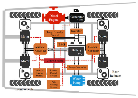
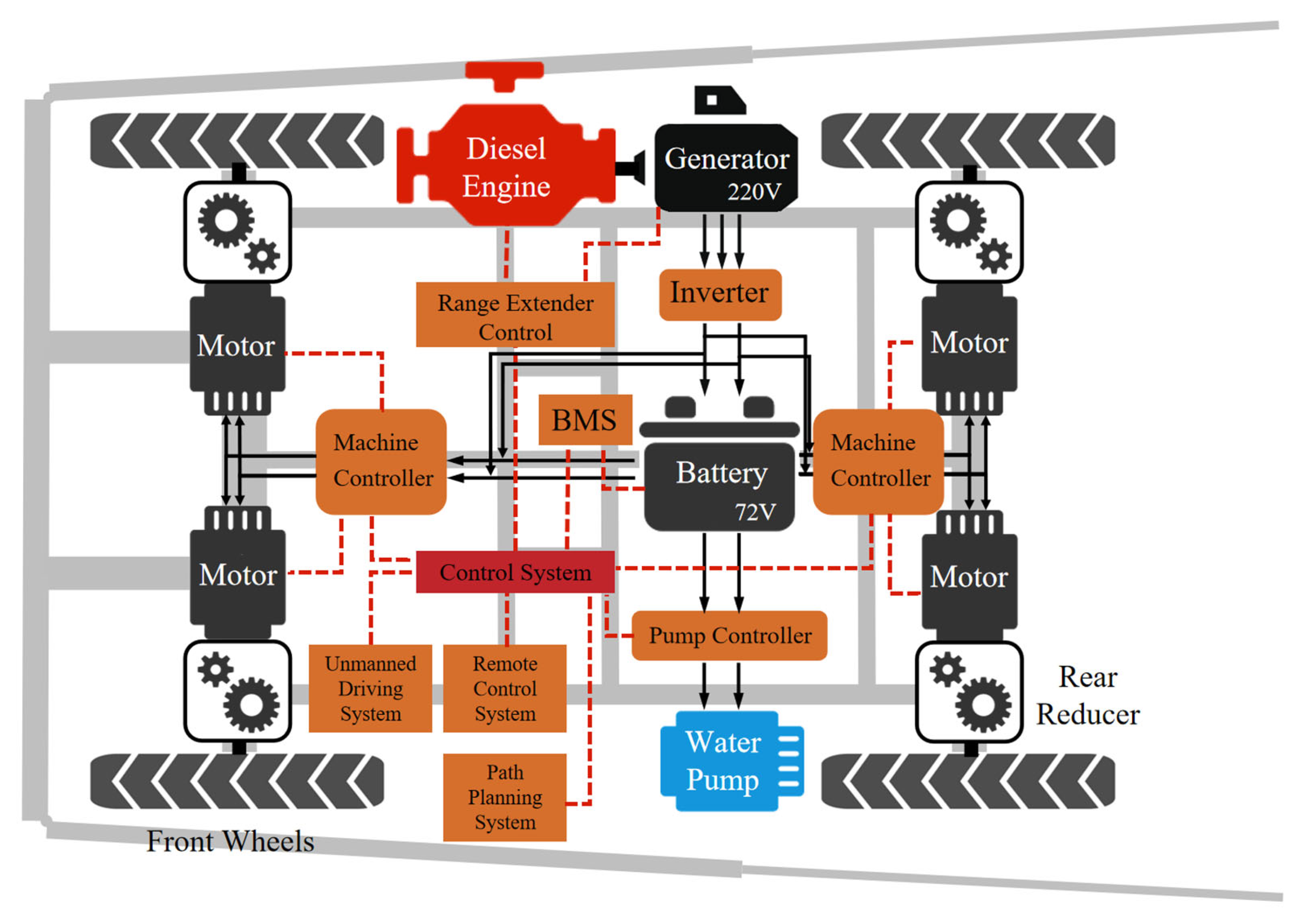
The overall structure of the 3WPZ-300 300 (Shandong Xiangrui, Linyi City, Shandong Province, China) unmanned range-extended sprayer is illustrated in Figure 1, and its basic parameters are presented in Table 1 [17,18,19]. With a microcontroller unit (MCU) serving as the central controller, the sprayer integrates the spraying system, autonomous driving system, remote control system, path planning system, range extender control system, and drive control system. It adopts a driving configuration consisting of four-wheel hub motors coupled with reducers. The range-extended system is composed of a range extender (integrating an engine and a generator), a battery pack, drive motors, and reducers; the specifications of these key components are detailed in Table 2.
Figure 1.
Overall structure of the 3WPZ-300 unmanned range-extended sprayer.
Table 1.
Basic parameters of the vehicle.
Table 2.
Key component parameters.
According to the operational status of the engine, the operating modes of the range-extended sprayer are classified into pure electric mode, range-extended mode, and stationary charging mode. In pure electric mode, the entire sprayer is powered by the battery pack, which supplies energy to the drive motors and the water pump through the motor controller and pump controller, respectively. In range-extended mode, the power is provided by the range extender, whose power generation output is regulated by the central controller based on the power demand signals and state of charge (SOC) values collected during operation. In stationary charging mode, the sprayer can be recharged via the power grid.
2.2. Development of a Co-Simulation Platform for Range-Extending Spray Machines
2.2.1. Overall Structure of the Co-Simulation Platform
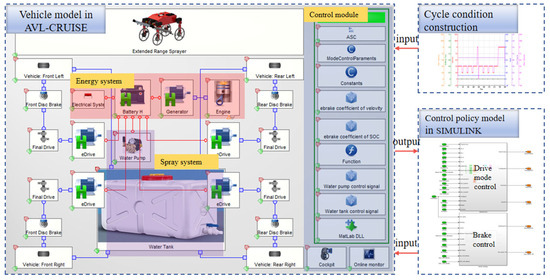
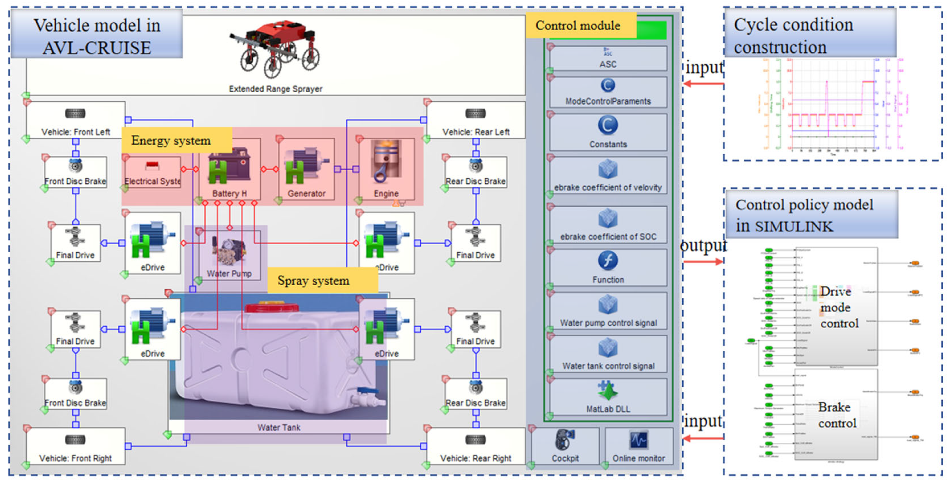
A joint simulation platform for the range-extended sprayer was constructed based on AVL CRUISE and Simulink, as depicted in Figure 2 [15,20]. The vehicle model was established by AVL CRUISE, while the vehicle’s EMS was constructed by Simulink, mainly encompassing two parts: the control strategy of the range extender and the control strategy of braking energy recovery. Through the components in the AVL-CRUISE R2019.2 software component library, such as the engine, generator, drive motor, tire module, MATLAB R2022a interface, and online monitoring, mechanical and electrical connections were carried out in accordance with the power system structure of the range-extended sprayer, and the connection of the data bus was completed to achieve the signal connection within the vehicle model. The MATLAB Dll module was utilized for the information interaction of the joint simulation platform. During the simulation process, vehicle parameters such as the engine fuel consumption MAP, motor efficiency, reducer reduction ratio, friction resistance coefficient, and transmission system efficiency were assigned based on the relevant test results of the 3WPZ-300 sprayer. In the figure, Cockpit is the driving component, used to simulate the control of the vehicle under real conditions, and the monitor module is employed to display the simulation process and results.
Figure 2.
Improved energy management model of the range-extended sprayer.
During the operation of the sprayer, the driving power at the same speed varies significantly due to the alteration of the remaining amount of the spray solution. Nevertheless, the AVL CRUISE software lacks a module for simulating the variation of the overall vehicle weight. Hence, a simulation model of the spray system was constructed via the Electric module and the Flange module in AVL CRUISE. The variation in driving power caused by the change in the weight of the water tank was simulated by the Flange module, which is rigidly and mechanically connected to the wheels through loading the torque characteristic module. The Map module can be utilized to set the curve of the tire resistance change corresponding to the weight change of the water tank. The power loss of the water pump was emulated by the Electric module, and the on-off and power of the water pump module were controlled by the Map module. The current mass of the water tank can be calculated based on the operation duration of the water pump and the spray rate, thereby establishing a connection between the two modules.
2.2.2. Vehicle Power Demand and Longitudinal Dynamics Model
Sprayers are required to meet both road transportation needs and field spraying operations [21,22,23]. Based on the power transmission characteristics of the range-extended sprayer’s powertrain, the power balance equation of the drive motor at time t is expressed as follows:
where Pm is the output driving power of the drive motor, kW; Ploss,m is the static power loss occurring in the process of converting the electrical power of the motor into mechanical power, kW. Since the demand power Pdem of the drive system is supplied by the range extender to meet the motor’s power demand, while considering the energy consumption of system accessories, charging demand power, and water pump power, Equation (2) can be rewritten as follows:
where Pe is the mechanical output power of the engine, kW; Pb is the power of the power battery, kW; Pp is the water pump power of the range-extended sprayer, kW; η1 is the vehicle transmission efficiency, %; η2 is the efficiency of the power conversion device, %.
Under driving cycle conditions, the total required driving power of the vehicle can be expressed as
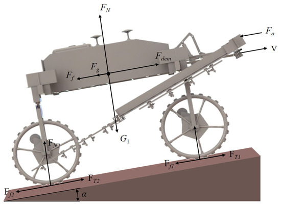
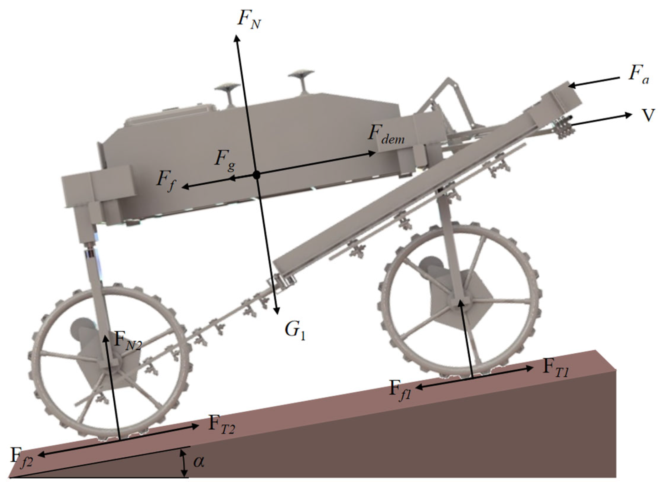
where m is the total mass of the range-extended sprayer, including the water tank mass and vehicle curb mass, kg; v(t) is the vehicle speed at time t, m/s; Fdem is the driving force of the powertrain under the operating cycle, N; Ff is the rolling resistance, N; Fa is the aerodynamic drag, N; and Fg is the gradient resistance, N.
The longitudinal vehicle dynamics model can be expressed as
where ρa is the air density, kg/m3; CD is the aerodynamic drag coefficient; A is the frontal area, m2; cr is the rolling resistance coefficient; and α(t) is the road gradient at time t.
The force analysis diagram of the sprayer at time t during its traveling process is depicted as shown in Figure 3 [22].
Figure 3.
Force analysis diagram of the sprayer.
2.2.3. Engine Model
In the research on energy management strategies (EMS), a quasi-static model is generally adopted for the engine. The overall engine efficiency is defined as the ratio of the output (mechanical) power to the input power (the chemical power of the fuel). Specifically, the fuel chemical power can be expressed as a function of the fuel mass flow rate and the lower heating value (LHV) of the fuel, as follows [24]:
where ηice is the engine efficiency, %; Pe is the mechanical output power of the engine, kW; Pfuel is the chemical power of the fuel, kW; Te is the engine torque, N·m; ωe is the engine angular velocity, rad/s; ṁf is the fuel mass flow rate, kg/s; Qlhv is the low heating value of diesel fuel, kJ/kg.
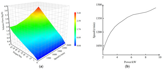
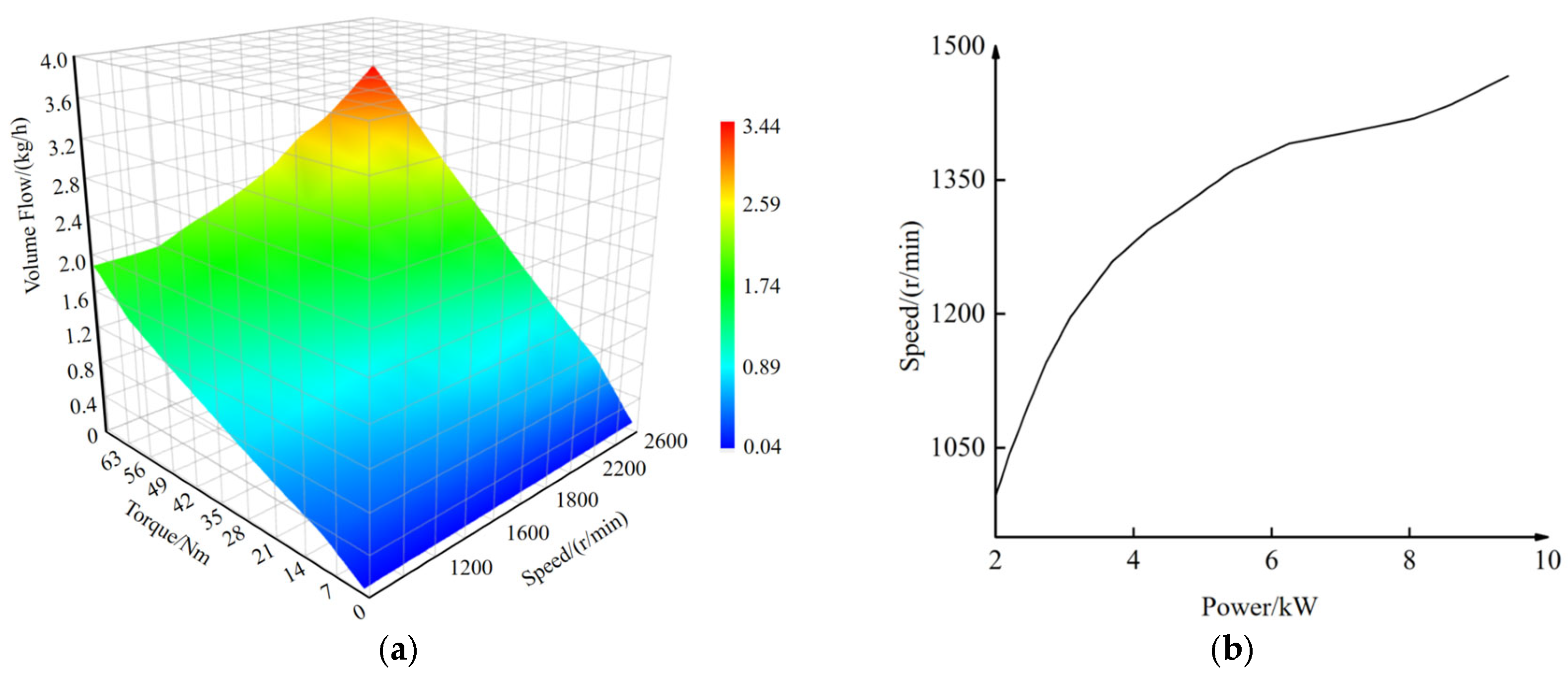
In a range-extended hybrid power system, the engine and generator are typically regarded as an integrated unit, referred to as the range extender. Since there is no mechanical coupling between the range extender and the sprayer’s drivetrain, the engine can operate at maximum efficiency along its optimal operating line (OOL). To optimize fuel economy, the engine’s operating points and fuel consumption can be determined by integrating the engine fuel consumption map (Figure 4a) and the speed/torque data at its optimal power points (Figure 4b).
Figure 4.
Engine model: (a) engine fuel consumption map; (b) engine optimal operating curve.
2.2.4. Generator and Driving Motor Models
To reduce the computational burden of the system, the dynamic characteristics of the motor models for the range-extended sprayer are neglected. Considering the conversion efficiency between electrical and mechanical power, a static efficiency MAP lookup table is employed as the motor model. The electrical power expression, calculated based on the torque demand, is given as follows [25]:
where Pdem ≥ 0 denotes the power consumption state; Pdem < 0 denotes the power generation state; Pm is the mechanical power of the motor, kW; and ηem (ωem, Tem) is the efficiency at the current angular velocity and torque, %.
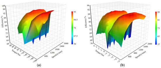
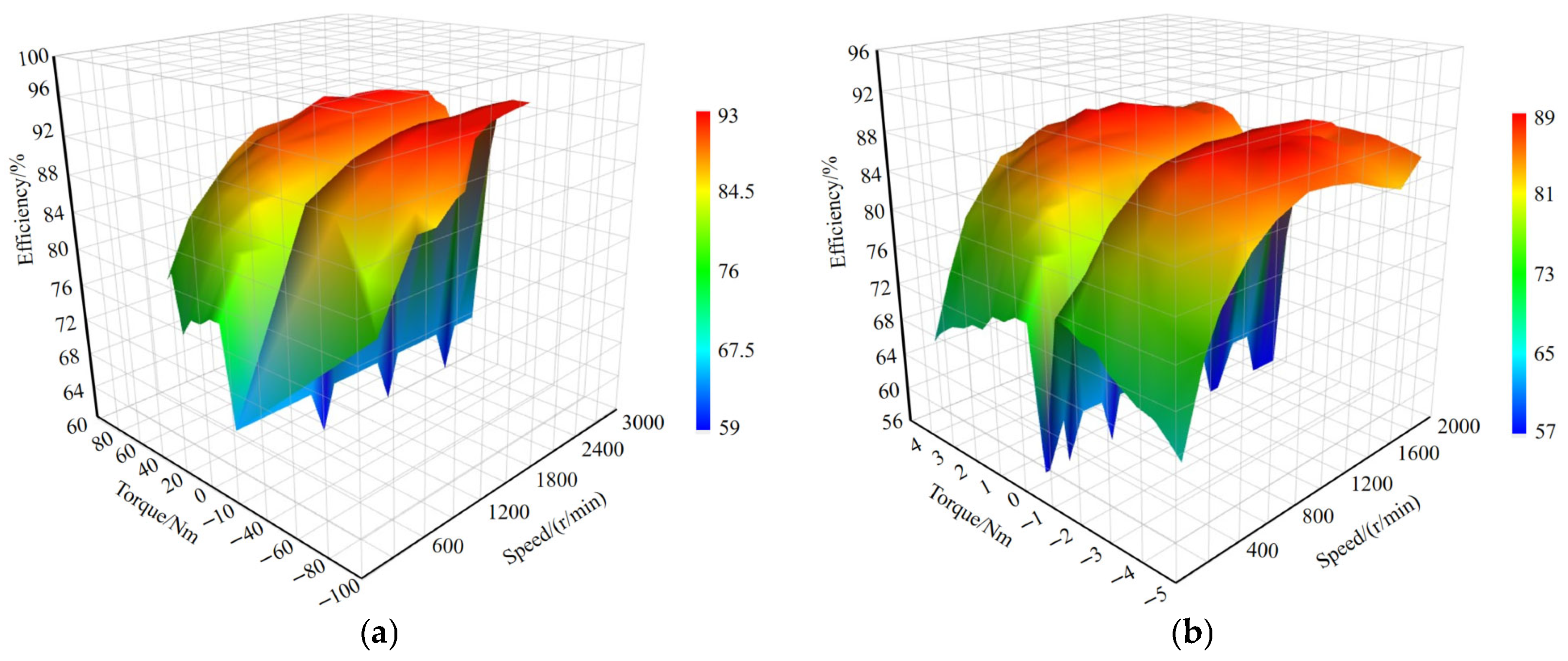
Based on the selected parameters of the range-extended drive system, the efficiencies of the motors were evaluated. Figure 5a illustrates the efficiency MAP of the 8 kW rated power generator, while Figure 5b presents the efficiency MAP of the 1 kW rated power driving motor. The generator achieves a peak generation efficiency of 93%, whereas the driving motor reaches a maximum driving efficiency of 89%.
Figure 5.
Motor model: (a) Generator efficiency map. (b) Driving motor efficiency map.
2.2.5. Battery Pack Model
The power battery is connected to the drive motor and generator through an inverter, supplying power to the drive motor or storing energy generated by the generator. This study employs an equivalent circuit model to represent the battery. The Rint model primarily focuses on the battery’s internal resistance and open-circuit voltage, while ignoring the effects of thermal dynamics and transient responses [26]. Based on the battery model, the key performance indicators of the power battery were further analyzed. Among them, the battery power state reflects the instantaneous power output capability of the battery under transient conditions such as acceleration, turning, and regenerative braking. The simulation results show that the power state is sufficient during the constant-speed operation stage but approaches its limit under transient conditions. The battery efficiency is mainly determined by internal resistance losses, with the average efficiency maintained between 92% and 95%, which decreases slightly during high-power charging and discharging. The battery state of health is affected by the SOC operating range and the depth of charge and discharge. In this study, the SOC is limited to the range of 30–80%, which helps to delay battery aging. The dynamic equation for the battery’s SOC is as follows [27,28,29]:
where Voc is the open-circuit voltage of a single power battery cell, V; SOC0 is the initial SOC value, %; R is the charge–discharge internal resistance of a single power battery cell, Ω; Pb is the output power, kW; Q is the capacity, Ah; I is the battery current, A.
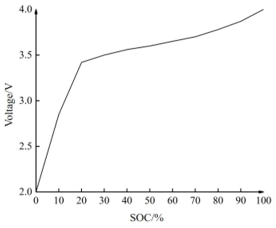
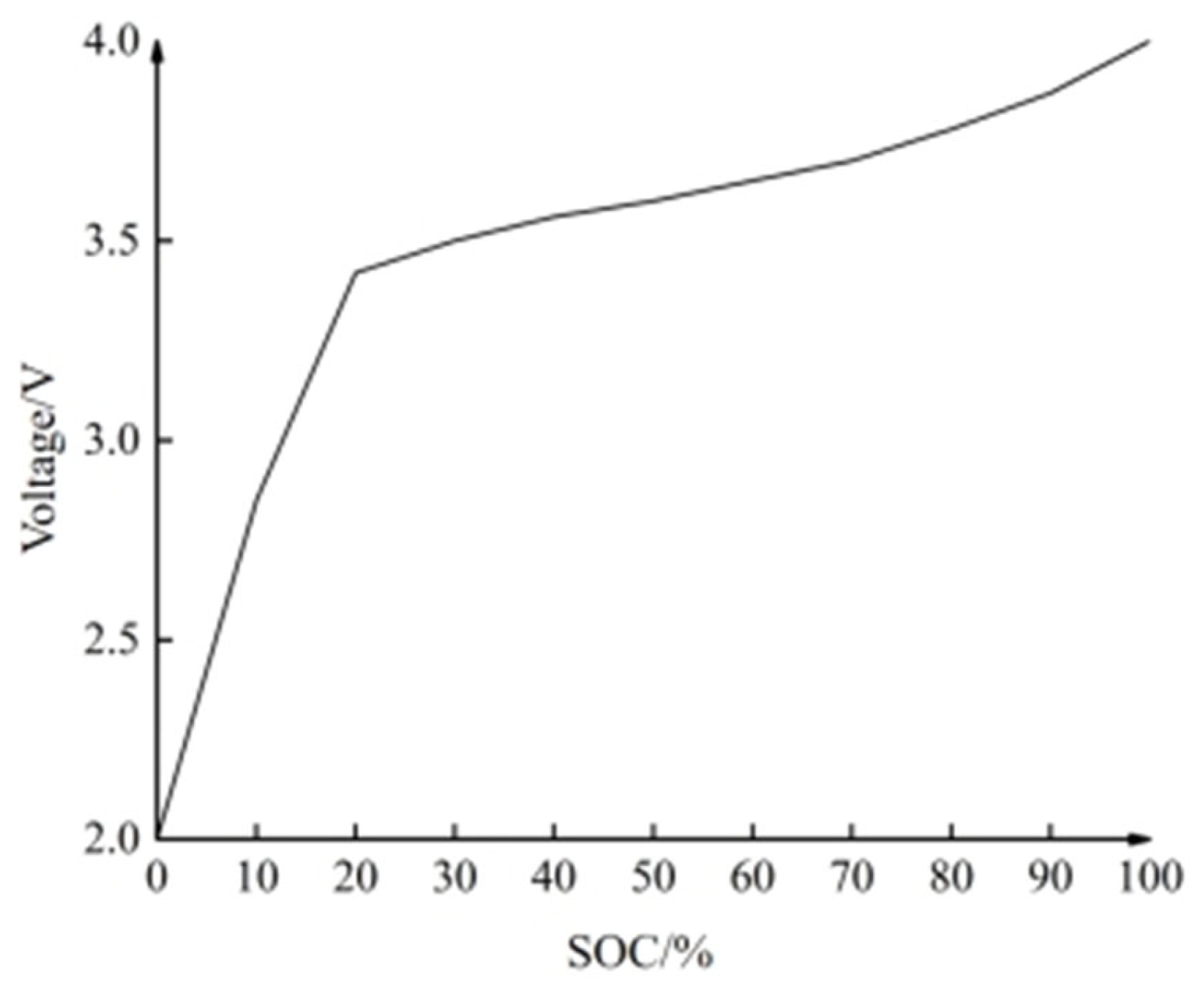
The open-circuit voltage versus state of charge (V-SOC) curve of the 100 Ah rated capacity power battery pack is depicted in Figure 6. The voltage of a single cell drops sharply at approximately 3.4 V. To extend the service life of the battery pack, the SOC threshold should be set above 20%. Considering the battery discharge characteristics, 30% and 80% are selected as the battery capacity thresholds.
Figure 6.
The open-circuit V-SOC curve.
2.2.6. Dynamics Model of the Spraying System
Compared with conventional road vehicles and agricultural tractors, components such as the water pump and water tank in a sprayer exert a significant impact on the total power demand during operation. Furthermore, the continuous variation of the remaining liquid in the tank leads to noticeable fluctuations in power demand, primarily reflected in its influence on tire rolling resistance.
However, the native component library of AVL-CRUISE lacks modules capable of dynamic mass adjustment. Consequently, this study proposes an innovative solution based on modular combinatorial modeling. By integrating the existing Motor, Flange, MAP, and Function modules, a dynamic simulation model for the spraying system with mass-wheel resistance coupling characteristics is constructed. The specific implementation paths are as follows:
- (1)
- Water pump module: A water pump model is first established using the Motor module. Combined with the MAP module, dynamic control of the water pump’s start–stop logic and power output is achieved to simulate the impact of intermittent pump operation on the vehicle’s energy flow.
- (2)
- Dynamic mass simulation: The relationship between water pump power and spray flow rate is defined via the MAP module, allowing the current spraying rate to be derived from the pump’s power signal. Subsequently, the Function module calculates the remaining liquid volume based on the initial tank capacity, spraying rate, and operation time.
- (3)
- Resistance characteristic modeling: A functional curve mapping the tank mass to the wheel-end resistance is constructed using the MAP module, enabling real-time mapping of gradient variations in rolling resistance under different liquid levels. The Flange module is then employed to apply the corresponding resistance torques to the wheel ends.
The dynamics model of the spraying system not only effectively characterizes the impact of the water pump on the total power demand but also provides essential data support for the optimal design of the sprayer. Furthermore, through this comprehensive simulation approach, the performance of the sprayer can be analyzed more thoroughly under diverse operating conditions.
As the mass of the water tank varies continuously during operation, it ultimately affects the wheel-end resistance. The corresponding dynamic equations can be formulated as follows:
where TD is the wheel rim torque exerted by the water tank, N·m; mt is the mass of the water tank at time t, kg; r is the wheel radius, m; M0 is the initial mass of the water tank, kg; Qs is the spray rate, kg/s.
2.2.7. Driving Cycle Design
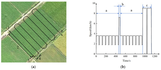
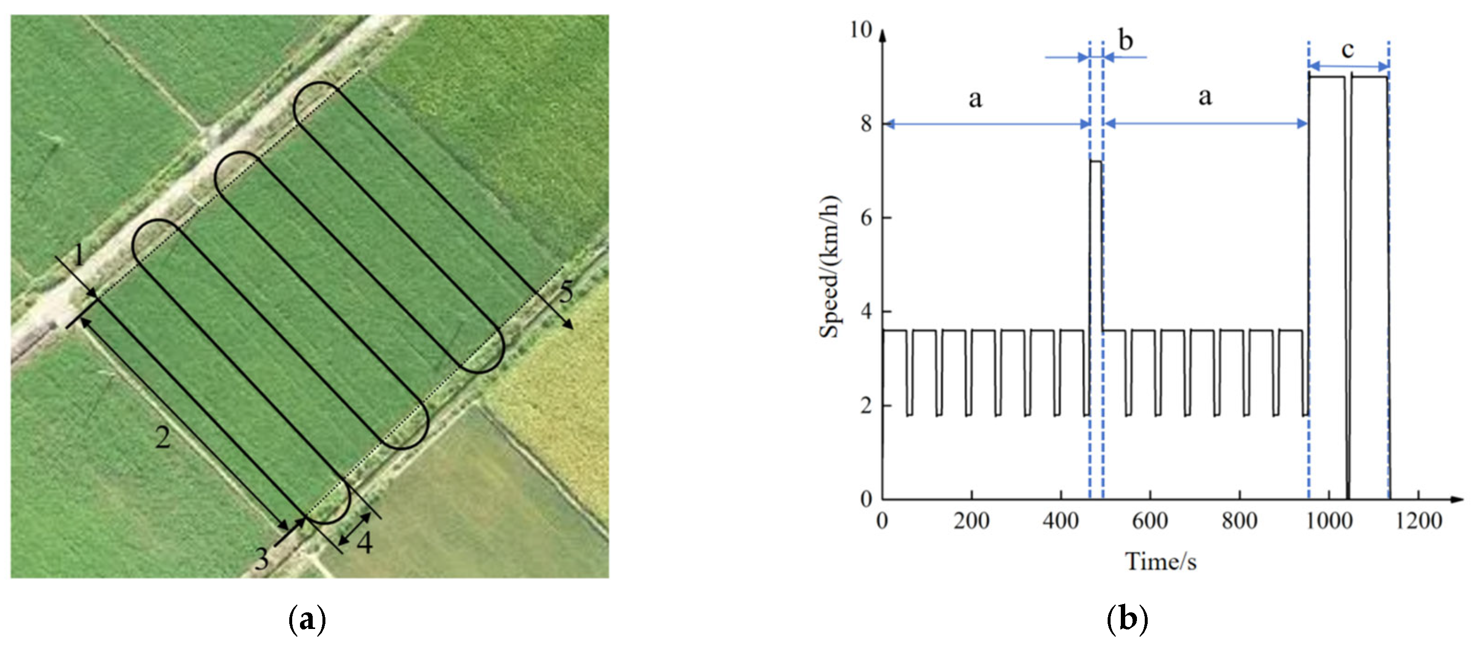
As a type of non-road mobile machinery (NRMM), the operating scenarios of sprayers differ significantly from those of urban road vehicles, as their operations involve direct interaction with soil. Based on various autonomous driving conditions during actual sprayer operation, the working conditions in independent operation areas can be categorized into straight-line driving and field turning maneuvers. Straight-line driving is further subdivided into uniform acceleration entry, constant-speed driving, and uniform deceleration exit. Additionally, the continuous cyclic operation includes phases such as acceleration to the next operation area and acceleration to the chemical refill point followed by a return.
To further clarify the distribution characteristics of energy consumption of the range-extended sprayer at different operation stages, a quantitative analysis of energy consumption under the five operating states shown in Figure 7 was conducted in this study. Based on the vehicle dynamics model (Equation (5)) and the power balance equation (Equation (2)), combined with the parameters of the whole vehicle and key components listed in Table 1 and Table 2, the proportions of energy consumption under the five operating states were obtained.
Figure 7.
Cycle operation condition schematic diagram: (a) Homework path planning; (b) Cyclic operating condition design. Note: 1—Uniformly accelerated driving; 2—Constant-speed driving; 3—Uniformly decelerated driving; 4—Field turning maneuver; 5—Acceleration to the next operation area; a—Cyclic operation; b—Acceleration to the next operation area; c—Acceleration to the chemical refill point and return.
Uniform acceleration: This stage is the main energy-consuming stage during the start-up and transfer of field operations. The vehicle requires a relatively high power, which is mainly used to overcome inertial force and rolling resistance, accounting for approximately 18% of the total energy consumption. Uniform velocity: During field operations, uniform velocity represents the main stage of spraying operation, with stable duration and power demand, contributing the highest proportion of energy consumption, about 42%. Uniform deceleration: Energy consumption at this stage is relatively low, mainly used to maintain the operation of the control system and auxiliary systems. In addition, part of the energy can be recovered to the battery through the regenerative braking system, accounting for about 8%. Field turning operation: The vehicle speed is low at this stage, but the steering resistance is large, and the drive motor needs to adjust its output frequently, with an energy consumption proportion of about 12%. Acceleration to the next operation area and chemical solution replenishment point and return: This stage involves long-distance transfer under no-load or full-load conditions. The variation in vehicle mass has a significant effect on energy consumption, accounting for about 20%. The energy consumption of the no-load segment during acceleration to the replenishment point and return is slightly lower than that of the full-load segment. The driving cycles are illustrated in Figure 7.
2.2.8. Energy Management Control Model
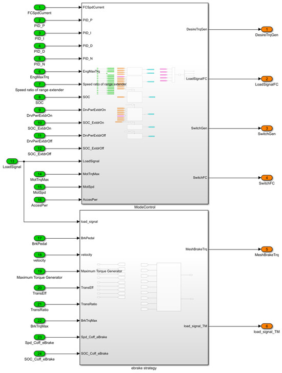
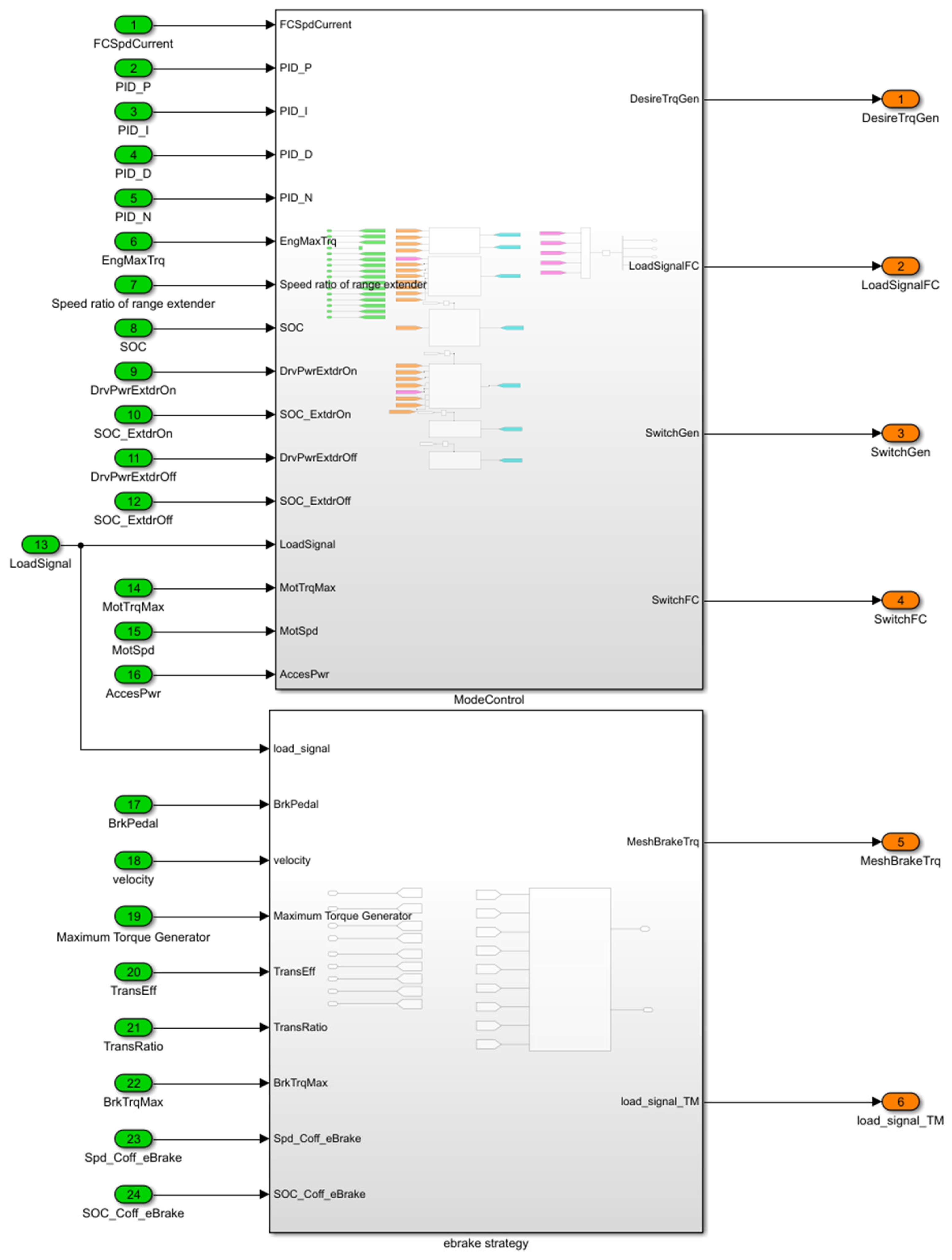
The vehicle Energy Management System (EMS) is developed in Simulink, as illustrated in Figure 8 [27], and integrated into the AVL-CRUISE environment via the MATLAB DLL module. It mainly consists of two components: the range extender control strategy and the regenerative braking control strategy.
Figure 8.
Energy management control model based on Simulink.
The range extender control strategy is responsible for calculating and outputting the engine switching signal (SwitchFC) and the generator switching signal (SwitchGen) based on parameters such as vehicle velocity (Velocity), current motor speed (MotSpd), and load signals (Load_Signal). This strategy regulates the start–stop status of the range extender through input signals in AVL-CRUISE, while simultaneously outputting the engine load signal (LoadSignalFC) and the generator torque demand signal (DesireTrqGen) to adjust the generation power. Furthermore, the regenerative braking control strategy manages the braking torque produced by the driving motor by outputting the mechanical braking torque signal (MeshBreTrq) and the traction motor load signal (LoadSignalTM), thereby realizing energy recovery.
2.3. Energy Management Strategy Model
During the operation of traditional sprayers, engine working conditions were subjected to dynamic fluctuations in the operating load, making it difficult to maintain the combination of engine speed and torque within a high-efficiency and economical range. In contrast to traditional sprayers, the engine and the drive system of the range-extended sprayer were decoupled. As an independent power generation unit, the engine could operate stably along the Optimal Operating Line (OOL) and within high-efficiency fuel economy regions. The core of the energy management for this system lay in the control of the range extender’s operating points in range-extended mode, which optimized the overall energy utilization efficiency by dynamically regulating the engine’s operating state.
Energy management strategies (EMS) were generally categorized into two types: rule-based and optimization-based strategies. Rule-based strategies offered the advantages of simplicity and ease of implementation; however, their primary drawback was the difficulty in achieving optimal control across the entire driving cycle due to continuously varying working conditions. Although dynamic optimization algorithms (such as Dynamic Programming) could achieve global optimality, they represented an ideal approach that required prior knowledge of future driving conditions. In this study, a fuzzy control-based EMS optimized by the Particle Swarm Optimization (PSO) algorithm was proposed. Additionally, a rule-based multi-point power follower strategy and a standard fuzzy control EMS were established for the range-extended sprayer. This study aimed to conduct a comparative simulation analysis of three indicators—fuel consumption, power consumption, and equivalent fuel consumption (detailed in Section 2.4)—to verify the superiority of the PSO-optimized fuzzy control EMS. To ensure the validity of the simulation results, all three energy management strategies (EMS) were tested on the same test bench and simulation model, under identical constraints (battery SOC thresholds and range extender start–stop logic) and with the same control objective of minimizing equivalent fuel consumption.
2.3.1. EMS Based on Fuzzy Control
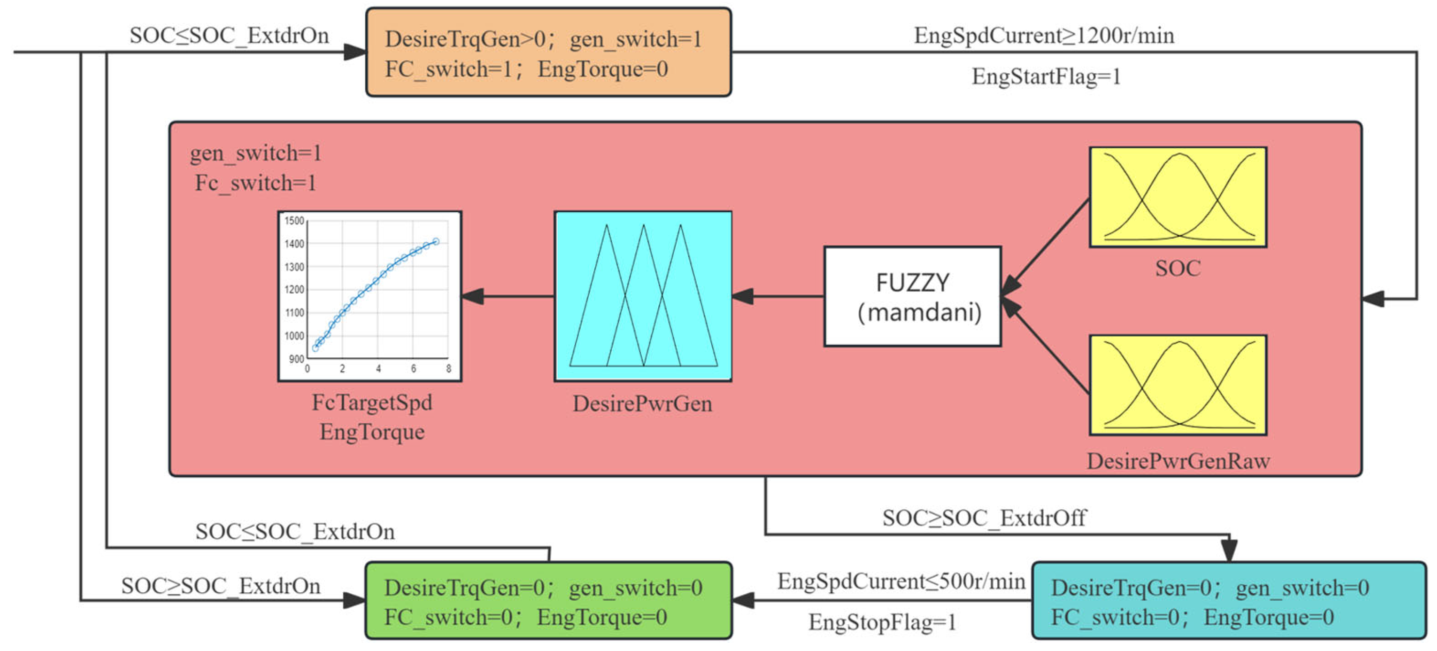
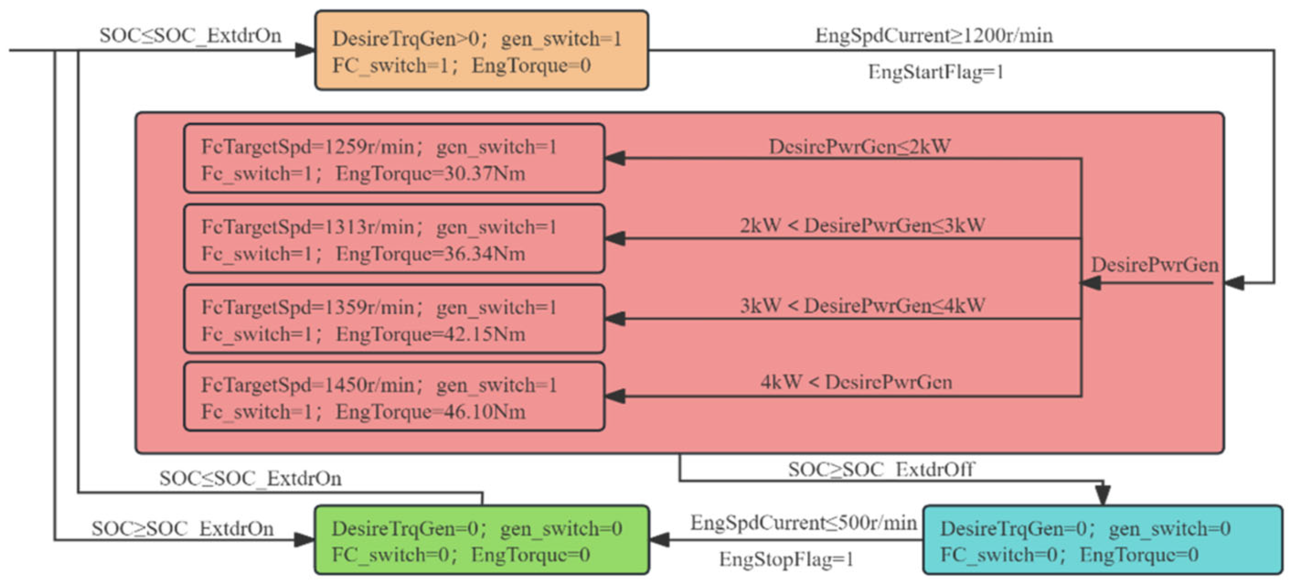
In the design of the fuzzy control EMS, an intelligent decision-making system is established based on fuzzy set theory, and the control logic of complex nonlinear time-varying systems is described through linguistic variables. For the energy management requirements of the range-extended sprayer, the fuzzy controller needs to satisfy dual constraints: the SOC of the power battery must be maintained within the safe threshold range (30–80%), and the output power of the range extender must be matched in real time with the dynamic demands of the entire machine. The fuzzy controller in this study adopts a dual-input single-output architecture: the input variables are the total machine power demand and battery SOC, and the output variable is the engine target power. Then, based on the engine’s optimal operating curve map, interpolation calculation is performed to determine the optimal speed-torque combination of the engine. The Mamdani-type fuzzy inference system is selected, and its rule base adopts the “IF-THEN” statement structure (e.g., IF the total machine power demand is high and SOC is low, THEN the range extender power is high). The principle of the EMS is detailed in Figure 9.
Figure 9.
Schematic diagram of the fuzzy control EMS.
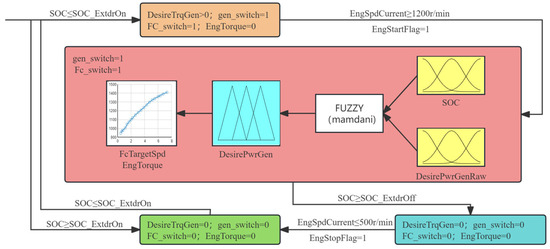
As illustrated in Figure 9, the generator switch signal is denoted as FC_switch, and the engine switch signal is denoted as gen_switch. During the operation of the range-extended sprayer, when the initial SOC is greater than SOC_ExtdrOn (i.e., the battery power exceeds the range extender startup threshold), the battery is fully charged and the entire machine operates in pure electric mode. As the spraying operation proceeds, the battery power continuously decreases. When the battery SOC is less than or equal to SOC_ExtdrOn, the battery can no longer maintain the normal operation of the entire machine, the range extender starts to operate, and the entire machine enters range-extended mode. First, the generator drives the engine to reach the target speed. During this process, the generator needs to output torque, so the generator target torque signal DesireTrqGen is greater than 0, while the engine does not need to output torque, so EngTorque = 0. When the speed reaches the target speed (i.e., EngSpdCurrent ≥ 1200 rpm), the engine start signal is activated (i.e., EngStartFlag = 1), and the engine starts to operate according to the set rules. When the battery power is greater than or equal to the range extender shutdown threshold (i.e., SOC ≥ SOC_ExtdrOff), the engine stops working.
Common methods for constructing membership functions include the fuzzy statistical method, expert experience method, and parametric function assignment method. Among them, triangular, trapezoidal, and Gaussian functions are widely used due to their clear mathematical characteristics and ease of implementation. Considering computational efficiency and engineering applicability, this study selects the triangular membership function defined by Equation (12) to construct the fuzzy rule base.
where A(1) is the left endpoint of the membership function; A(2) is the vertex of the membership function; A(3) is the right endpoint of the membership function.
Table 3 presents the membership function configuration scheme of the Mamdani-type fuzzy control system: The membership functions of the total machine demand power signal and battery SOC signal both adopt a triangular distribution (trimf), and their fuzzy domains are divided into five fuzzy subsets: [NB (negative big), NS (negative small), ZO (zero), PS (positive small), PB (positive big)]; the membership function of the engine power signal also adopts the trimf form but is mapped to different power domain intervals.
Table 3.
Fuzzy inference rule table.
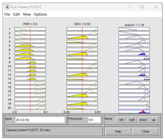
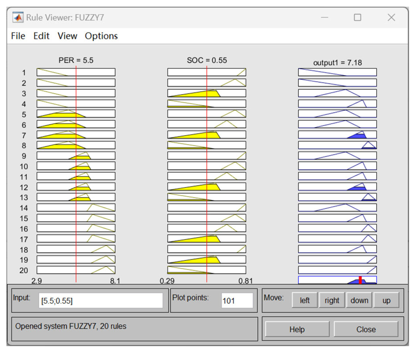
The setting of relevant parameters and the implementation of fuzzy rules are achieved through the MATLAB toolbox. The implementation interface of fuzzy rules in the MATLAB Fuzzy Logic Toolbox is shown in Figure 10. This design significantly reduces the computational complexity of real-time control while ensuring the accuracy of fuzzy reasoning through parametric modeling.
Figure 10.
The implementation interface in the MATLAB Fuzzy Logic Toolbox.
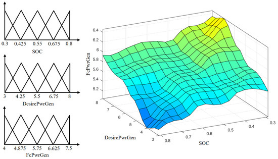
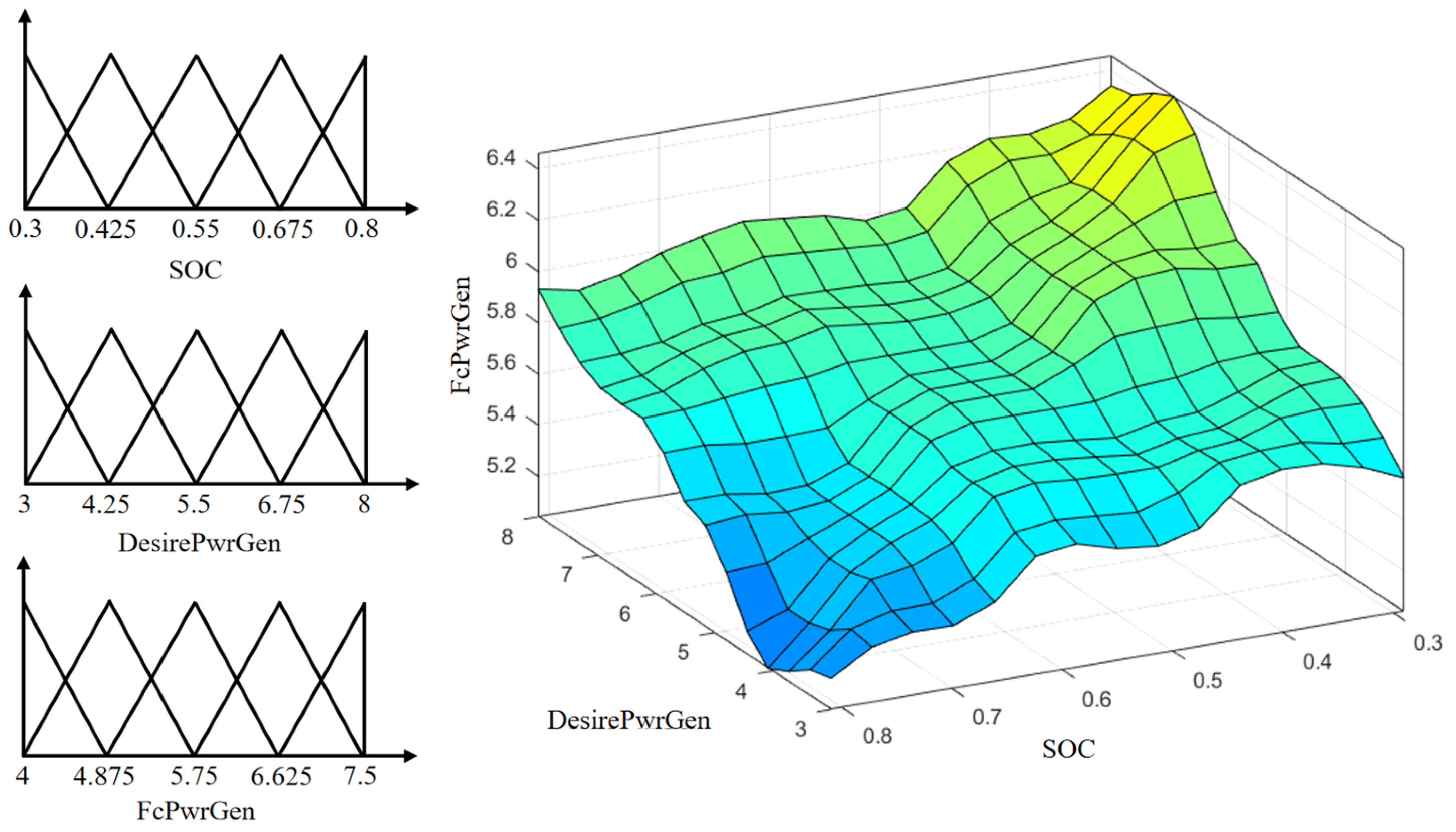
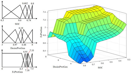
A fuzzy controller is constructed in MATLAB. The membership function and the resulting fuzzy inference surface are depicted in Figure 11. In the fuzzy inference surface graph of the Mamdani fuzzy system, the X-axis represents the battery pack SOC signal, the Y-axis represents the sprayer demand power signal, and the Z-axis represents the engine target power.
Figure 11.
Fuzzy membership function graph and fuzzy surface.
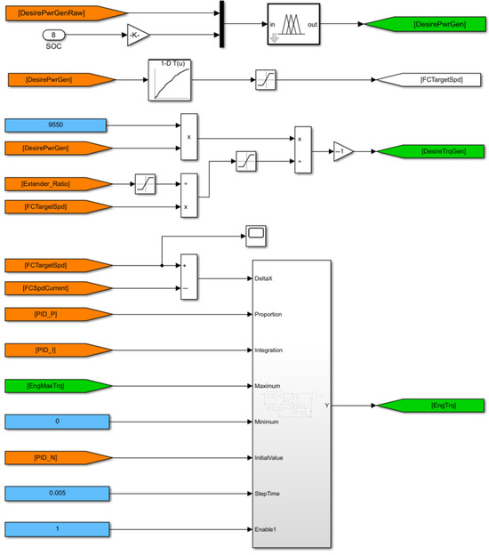
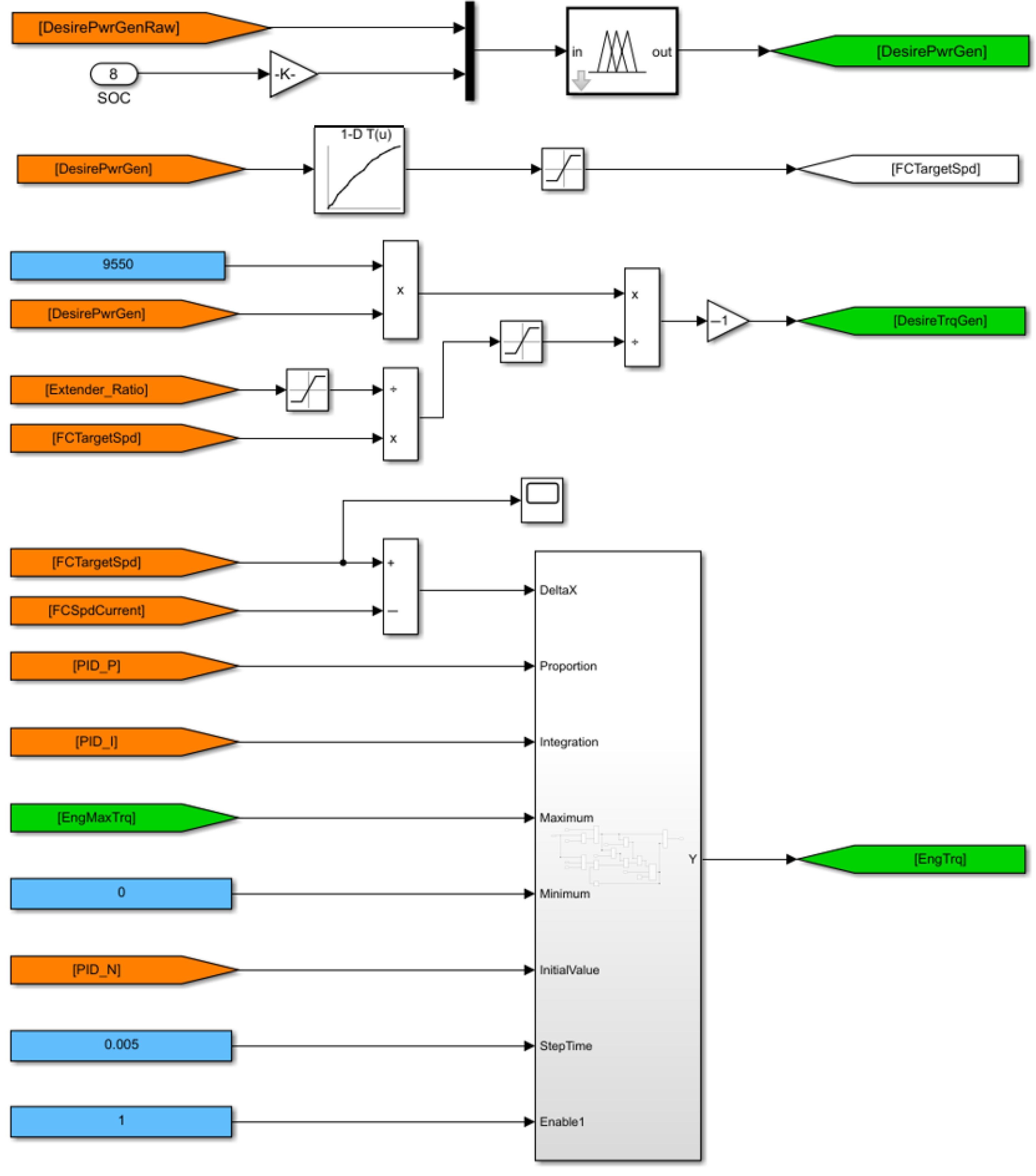
Figure 12 shows a partial model of the fuzzy control EMS. The EMS mainly introduces two input quantities of the fuzzy controller, namely the raw total machine power demand signal (DesirePwrGenRaw) and the battery power signal (SOC), and outputs an engine target power signal (DesirePwrGen). The range extender target speed (FCTargetSpd) is then determined via the engine’s optimal operating curve. The target torque calculation module computes the range extender torque signal magnitude and realizes closed-loop control of engine speed through the established engine PID controller. By inputting the difference between the target speed and actual speed, the engine can be maintained at the target speed and controlled to output different torque signals.
Figure 12.
Fuzzy Logic Control-based Energy Management System (EMS) Model.
2.3.2. Fuzzy Control EMS Optimized by Particle Swarm Optimization (PSO)
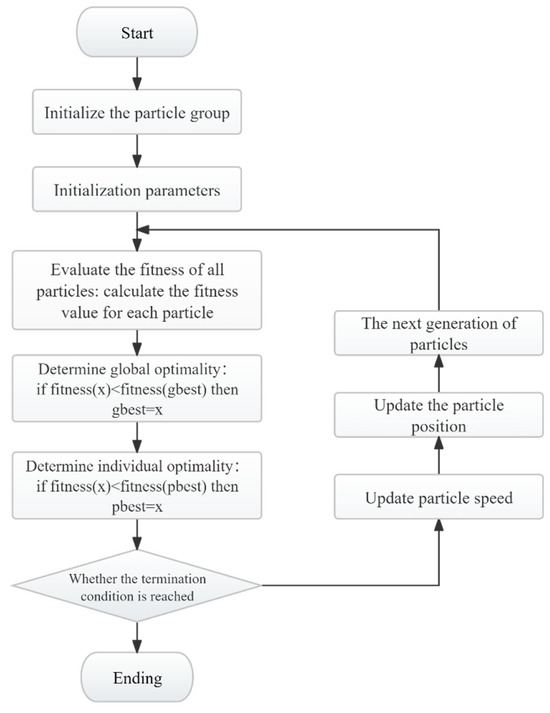
The design of membership functions and fuzzy rules in a fuzzy controller is highly subjective, which may prevent the system from achieving a global optimal solution. To improve control performance, a fuzzy control energy management strategy optimized by the Particle Swarm Optimization (PSO) algorithm is further proposed. PSO is a swarm intelligence-based optimization algorithm proposed by Eberhart and Kennedy in 1995 [30,31], inspired by the foraging behavior of bird flocks. In this algorithm, each potential solution is treated as a “particle” in the search space, with two primary attributes: position and velocity. Leveraging its global search capability, the PSO algorithm is integrated with the range-extended sprayer simulation platform. Through an iterative process, several turning points of the membership functions are defined as a particle swarm to optimize the membership function parameters, thereby improving the efficiency of the energy management system.
The formulas for updating the velocity and position of the particles are as follows:
where vi(t) is the velocity of the i-th particle at time t; w is the inertia weight, which controls the extent to which the particle maintains its current velocity; c1 and c2 are learning factors, which control the influence of the individual and global best positions on the velocity; r1 and r2 are random numbers within the range [0, 1]; pi is the individual best position of particle i; pg is the global best position; xi(t) is the position of the i-th particle at time t; xi(t + 1) is the new position of the i-th particle at time t + 1.
The basic process of the algorithm is depicted in Figure 13.
Figure 13.
Flowchart of the Particle Swarm Optimization (PSO) algorithm.
Optimization using the Particle Swarm Optimization (PSO) algorithm requires a clearly defined objective function. In the Equivalent Consumption Minimization Strategy (ECMS), both engine fuel consumption and the equivalent fuel consumption of the battery are jointly considered to identify the optimal engine operating points that minimize total fuel consumption. Generally, the expression for ECMS can be formulated as follows [32]:
where mequ is the total fuel consumption, L; mf is the engine fuel consumption, L; mb is the equivalent fuel consumption converted from battery energy consumption, L.
The engine’s fuel consumption can be obtained from the simulation results, while the battery’s energy consumption can be converted into equivalent fuel consumption through calculations. Thus, the total fuel consumption can be expressed as follows:
With equivalent fuel consumption as the optimization target, the smaller the objective function value, the better the economic performance of the sprayer, and the closer the optimized solution is to the global optimal solution.
During optimization, it is necessary to impose constraints on critical parameters in the sprayer simulation. The constraint conditions are as follows:
In the equation, Pbat_max and Pbat_min denote the upper and lower bounds of battery power, kW; Pe_max and Pe_min represent the upper and lower limits of engine power, kW; Pg_max and Pg_min signify the upper and lower limits of generator power, kW; Teng_min and Teng_max indicate the upper and lower limits of engine torque, N·m.
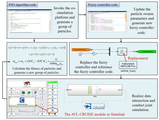
To optimize the fuzzy control energy management strategy (EMS), the codes for both the Particle Swarm Optimization (PSO) algorithm and fuzzy control logic are implemented in the MATLAB environment. Consequently, MATLAB serves as the master platform to invoke the co-simulation model, while AVL-CRUISE operates in a “called” state via the MATLAB Interface co-simulation mode.
Adopting the MATLAB Interface approach requires specific configuration of the co-simulation environment. Initially, the AVL-CRUISE components must be integrated into the Simulink library. This is achieved by setting the MATLAB working directory to the installation path (e.g., D:\AVL\CRUISE\…\matlab\work), enabling the AVL-CRUISE modules to be accessible in the Simulink Library Browser. Subsequently, the AVL-CRUISE module is linked to the Simulink EMS model via the data bus. To incorporate the fuzzy control code into the EMS model, the original fuzzy controller block is replaced by an Interpreted MATLAB Function block. Finally, the MATLAB DLL block in the AVL-CRUISE vehicle model is substituted with the MATLAB Interface block, while maintaining signal connections consistent with the MATLAB DLL configuration (Figure 14). By executing the PSO algorithm script in MATLAB, the co-simulation process is initiated to iteratively optimize the membership functions of the fuzzy controller.
Figure 14.
The optimization process of EMS is based on PSO algorithm.
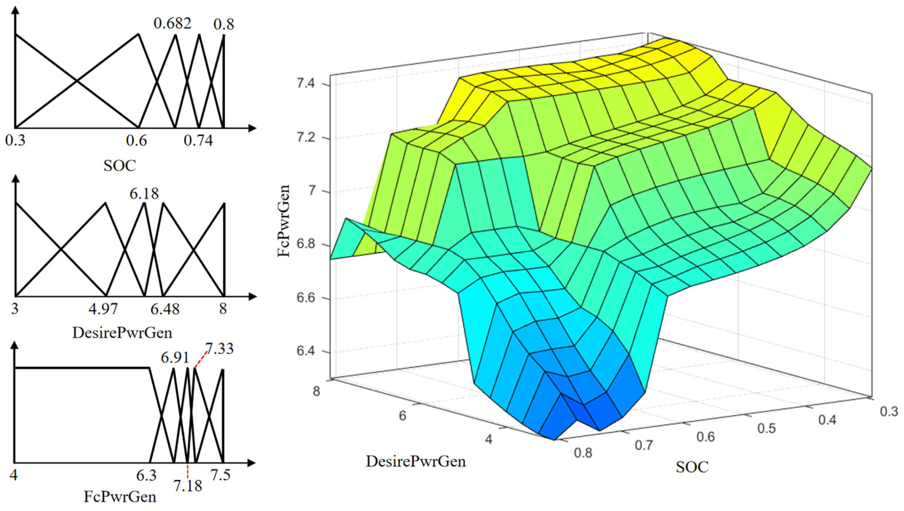
Both the input and output membership functions to be optimized consisted of five fuzzy subsets, each characterized by a Gaussian function. A total of 10 optimization parameters are selected, denoted as X1, X2, X3, X4, X5, X6, X7, X8, X9, X10. The PSO code generates a new particle swarm that satisfies the specified constraints. By assigning these parameters to the fuzzy control logic, updated control code is generated to invoke the co-simulation platform. Through an iterative process, the fuzzy membership functions that yield the minimum equivalent fuel consumption are identified as the global optimal solution of the PSO algorithm. The optimized membership functions and the corresponding fuzzy surface are illustrated in Figure 15.
Figure 15.
Optimized fuzzy membership functions and fuzzy control surfaces.
2.3.3. EMS Based on Multi-Point Power Follower
The primary advantage of the fixed-point management strategy is its ability to maintain the engine consistently at its optimal operating point. However, its drawbacks include frequent engine start–stop cycles and significant fluctuations in charging power, which adversely affect battery service life. In contrast, the power follower management strategy allows the range extender to operate based on the vehicle’s real-time power demand. Once activated, the engine can theoretically track the vehicle’s power requirements.
The advantages of this approach include stabilizing charging power, extending battery life, and increasing the engine’s operating duration per cycle, thereby reducing start–stop frequency. The disadvantage, however, lies in the high coefficient of variation of the total vehicle power demand during driving, which leads to frequent switching of engine operating points and subsequent deterioration of fuel economy.
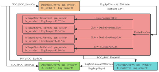
To address these issues, a multi-point power follower energy management strategy is developed by integrating the characteristics of the fixed-point strategy. This control strategy follows predefined logic, integrating signals such as battery State of Charge (SOC), vehicle speed, and engine speed to regulate the activation/deactivation of the range extender and adjust its output power. The critical factor in this strategy is the rational selection of the number of operating points. An insufficient number of points fails to meet the power demand, whereas an excessive number causes frequent operating point transitions and fuel economy degradation. In this study, four power points are selected to cover the vehicle’s power demand. The principle of the multi-point power follower EMS is illustrated in Figure 16.
Figure 16.
Multi-point power-following EMS principle.
2.4. Fuel Economy Experiment
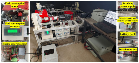
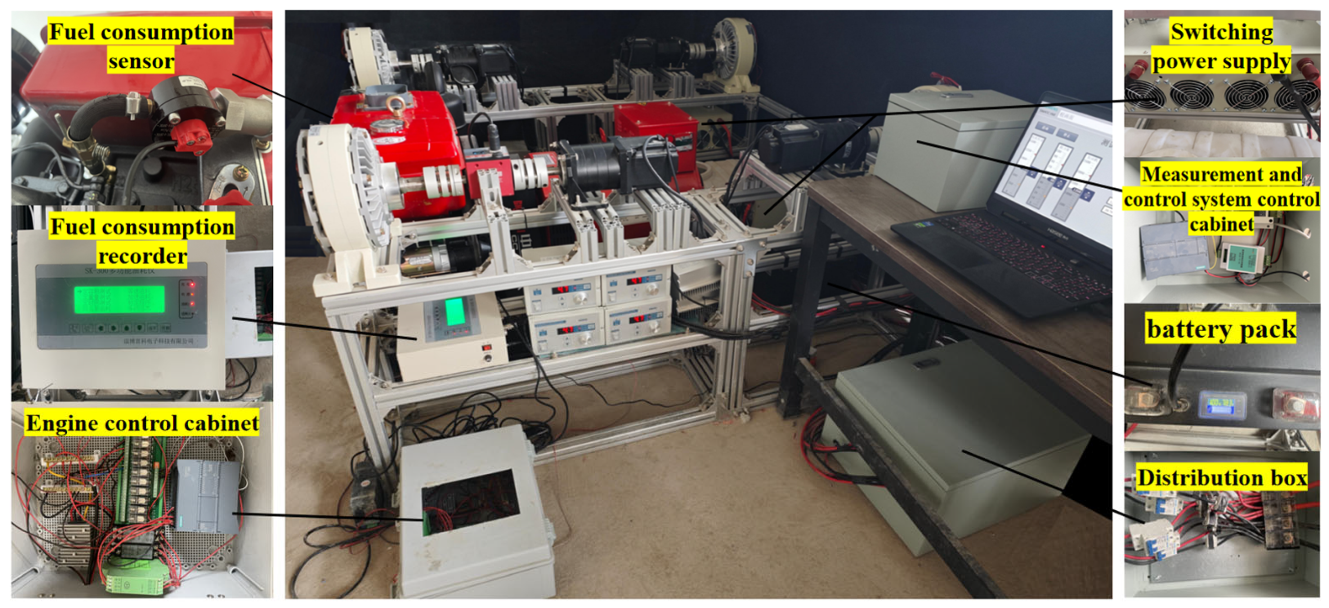
The integrated architecture of the energy management test platform for the range-extended sprayer is illustrated in Figure 17. It consists of five primary subsystems: the load simulation system, engine control system, power supply system, measurement and control (M&C) system, and range-extended powertrain.
Figure 17.
Extended-range spray machine test platform.
Specifically, the load simulation system replicates the resistance encountered during field operations as the external load for the powertrain under test. The engine control system manages engine startup, rotational speed, output power, and shutdown via real-time signaling. The power supply system is divided into two parts: the internal power system of the range-extended sprayer and the M&C power system of the test platform. The M&C system, composed of various sensors and signal transmission modules, enables real-time control and data monitoring of the load simulation, drive, and engine control systems, thereby providing necessary data support.
The test platform is used to verify the feasibility of the energy management strategies (EMS) in practical applications. Cyclic operation tests are conducted on the platform by integrating the driving cycle and EMS code into the M&C system. A host computer is employed to monitor and record real-time data, such as vehicle speed and battery State of Charge (SOC). Upon completion of the test, fuel consumption is measured via a fuel flow meter to validate the effectiveness of the improved models and optimized strategies.
The specific experimental procedures are as follows:
- (1)
- Configuration of the M&C environment: The sprayer’s EMS and driving cycle models are established in MATLAB/Simulink. Algorithmic code is generated via Simulink Coder and integrated into the M&C system. The EMS primarily involves converting the optimized fuzzy controller into executable code, using the current SOC and vehicle power demand (calculated by the PLC) as inputs.
- (2)
- Hardware implementation of control strategies: The generated control algorithms are imported into the PLC to implement PSO-optimized fuzzy control and driving cycle control. The PLC determines the target engine power and speed. The engine first achieves closed-loop speed control via a PID controller, followed by load power regulation through a switching power supply.
- (3)
- Spraying speed test: Based on the integrated Simulink driving cycle data, the PLC adjusts road resistance and driving motor speed in real time. The tracking performance of the motor speed relative to the target speed is recorded and converted into the actual operating speed.
- (4)
- Battery SOC test: Changes in the battery pack’s SOC are monitored in real time during cyclic operation. The charging/discharging current, voltage, and SOC values are recorded.
- (5)
- Fuel consumption test: During the cycle, the engine’s instantaneous fuel consumption is measured in real time using a fuel flow meter, and cumulative data are recorded.
- (6)
- Comparative tests of EMS: The multi-point power follower, standard fuzzy control, and PSO-optimized fuzzy control strategies are subjected to both simulation and platform tests under identical cyclic conditions. Three indicators—fuel consumption, power consumption, and equivalent fuel consumption—are recorded and compared. Using equivalent fuel consumption as the primary metric, error analysis is performed between simulation results and platform test data to evaluate the accuracy of each strategy.
3. Results and Discussion
3.1. Co-Simulation Results and Analysis of Different EMS
3.1.1. Analysis of Simulation Results for Multi-Point Power Follower EMS
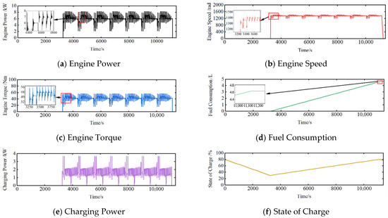
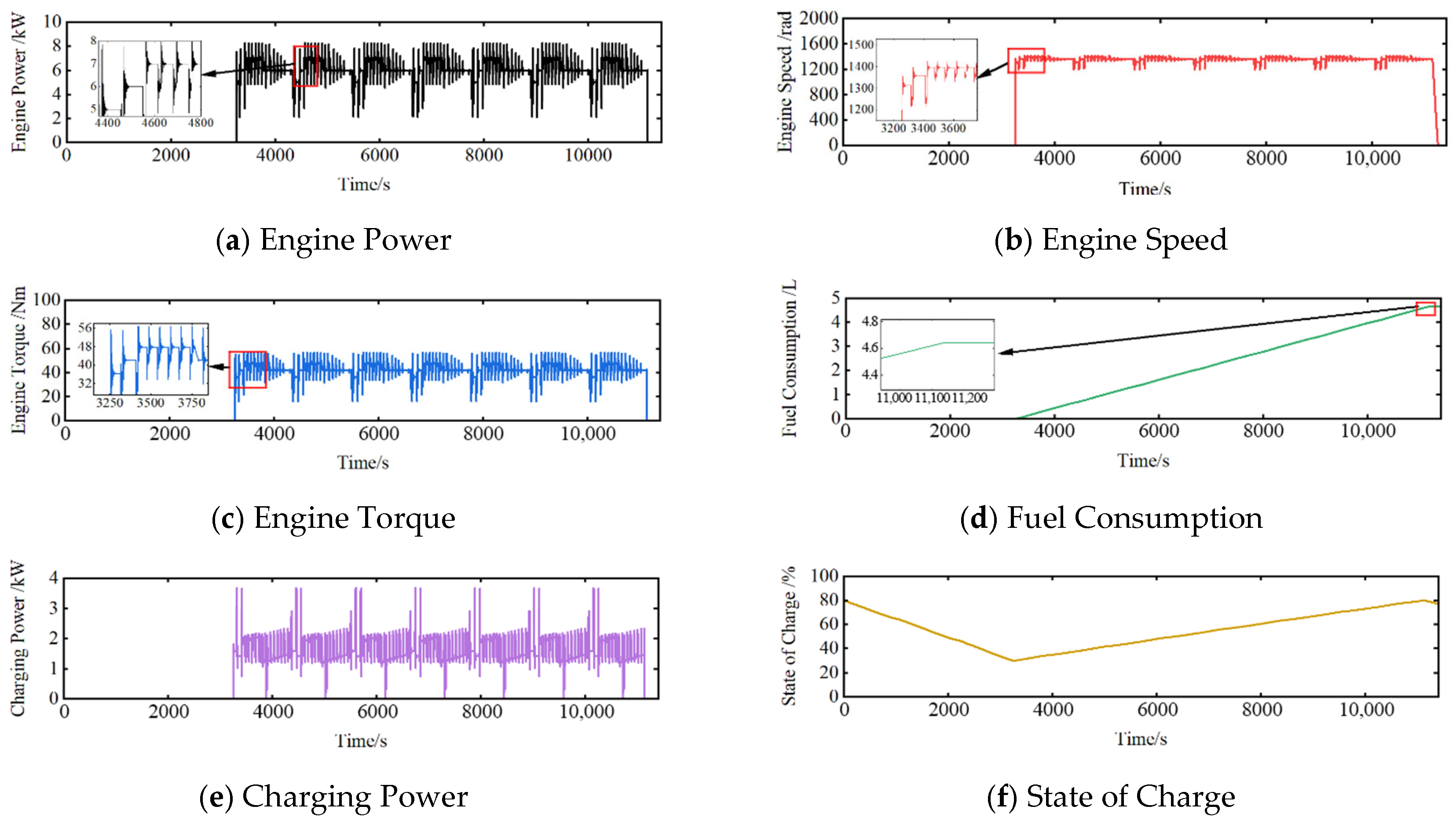
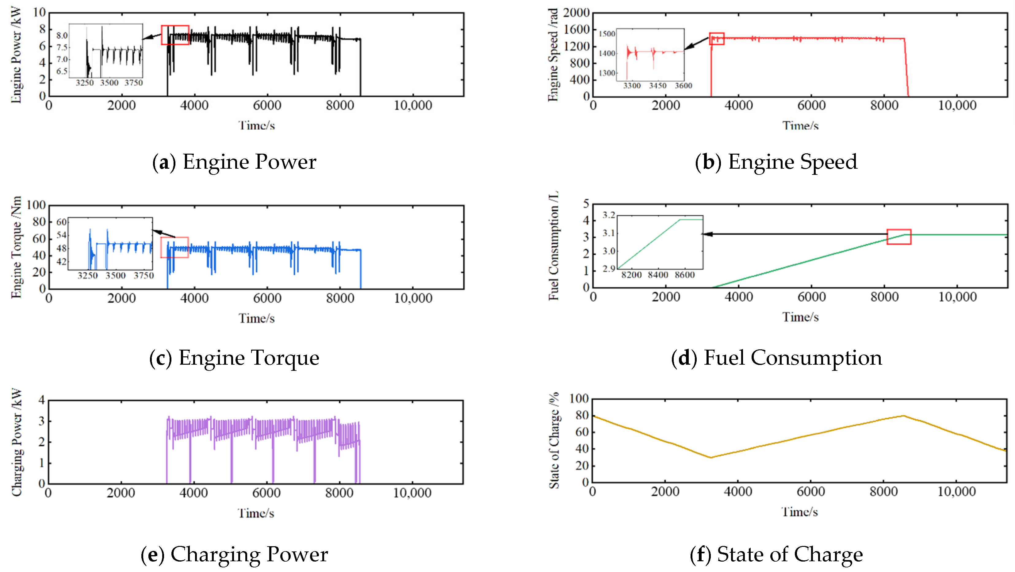
As illustrated in Figure 18, under the control of the multi-point power follower EMS, the initial battery State of Charge (SOC) is set to 80%. Combined with Figure 18f, it can be observed that the range-extended sprayer initially operates in pure electric (PE) mode. After approximately 3205 s, the SOC decreases from 80% to the predefined threshold of approximately 30%, triggering the activation of the range extender.
Figure 18.
Multi-point power-following EMS simulation results.
According to the magnified views in Figure 18a–c, the engine output power ranges from 4 to 8 kW, the rotational speed fluctuates between 1200 and 1450 rad/s, and the torque varies between 32 and 56 Nm. These parameters undergo a dynamic rising phase before transitioning to a relatively steady state with minor fluctuations. Under this strategy, the battery charging power exhibits significant fluctuations as the engine switches between different operating points. As shown in Figure 18e, the stable charging power ranges from 1 to 3 kW; however, the peak charging power reaches 4 kW, which exerts a substantial negative impact on battery cycle life.
In Figure 18d, fuel consumption exhibits a continuous cumulative growth trend, which is directly correlated with the power output and duration within a single engine start–stop cycle. Consequently, this has a relatively minor impact on engine service life, indicating that fuel economy under the multi-point power follower EMS is highly dependent on the selection of engine operating points.
These results are generally consistent with current research on agricultural machinery powertrain systems utilizing fixed-point and power follower energy management systems [12,15]. Nevertheless, challenges such as a high coefficient of variation (CV) of vehicle power demand and frequent switching of engine operating points remain prevalent during operation. The primary advantage of a fixed-point EMS is its ability to maintain the engine consistently at its optimal operating point; however, its drawbacks include frequent engine start–stop cycles and significant charging power fluctuations due to load variations, which adversely affect battery life. Conversely, the power follower EMS allows the range extender to track the vehicle’s power demand. While this stabilizes charging power, extends battery life, and reduces start–stop frequency by increasing the duration of each operating cycle, its disadvantage lies in the frequent switching of engine operating points caused by high power demand variance, which ultimately leads to deteriorated fuel economy.
3.1.2. Analysis of Simulation Results for Fuzzy Control EMS
As illustrated in Figure 19, under the designed driving cycle with the fuzzy control EMS, the range-extended mode is activated once the battery State of Charge (SOC) falls below the predefined 30% threshold.
Figure 19.
Fuzzy control EMS simulation results.
According to Figure 19a–c, the engine output power (5–8 kW), rotational speed (1300–1450 rad/s), and torque (45–60 Nm) exhibit periodic adjustments. The magnified views indicate that the fluctuation amplitudes of these three indicators gradually converge over time, demonstrating dynamic adaptive characteristics. However, the more frequent changes in output power, speed, and torque compared to the previous strategy exert a greater impact on engine service life.
Under the fuzzy control EMS, as shown in Figure 19e,f, the engine output power is adjusted according to the vehicle’s demand and current battery charge level. After the activation of the range extender, the stable charging power gradually decreases from 3 kW to 1 kW as the battery SOC recovers toward 80%. The small SOC fluctuation amplitude indicates a reduced negative impact on battery longevity. In Figure 19d, while fuel consumption increases over time, the growth rate remains relatively gradual. By selecting efficient engine operating points, the fuzzy control EMS satisfies the power demand while suppressing the rapid increase in fuel consumption, thereby verifying the system’s operational smoothness and the robustness of SOC control.
Current research on agricultural machinery powertrain systems frequently employs fuzzy logic-based energy management strategies. This inference mechanism, based on linguistic variables, aligns closely with expert experience and effectively facilitates multi-objective decision optimization under complex working conditions [30,33]. Nevertheless, the design of membership functions and fuzzy rules within the fuzzy controller remains highly subjective, which may prevent the resulting solution from achieving the global optimum [2,31].
3.1.3. Analysis of Simulation Results for PSO-Optimized Fuzzy Control EMS
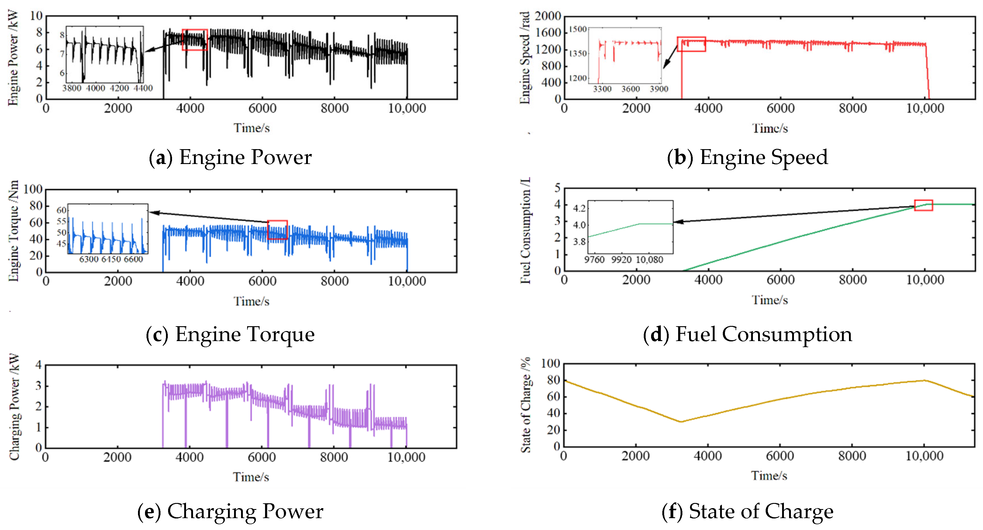
As illustrated in Figure 20, under the PSO-optimized fuzzy control EMS, the range-extended sprayer initially operates in pure electric (PE) mode. Once the battery energy is depleted to the range-extender activation threshold, the range extender is engaged. According to Figure 20a–c, the engine output power is concentrated within the 6.5–8 kW range, the rotational speed is maintained between 1350 and 1450 rad/s, and the torque varies within a relatively narrow interval of 42–54 Nm. Compared to the other two strategies, the fluctuation ranges of these three indicators are significantly narrowed, demonstrating high-concentration fluctuation characteristics. Among the three evaluated strategies, this scheme exerts the minimal impact on engine service life.
Figure 20.
PSO-Fuzzy EMS simulation results.
The engine output power simultaneously follows variations in both vehicle power demand and battery SOC. As shown in Figure 20e,f, the charging power gradually decreases from 3 kW to 2 kW. After the SOC drops from the initial 80% to the 30% threshold, it rapidly recovers to 80%, maintaining a stable SOC trajectory during the charging process. As shown in the magnified views in Figure 20d, the growth rate of fuel consumption is significantly reduced, remaining lower than that of the unoptimized fuzzy control EMS over the same duration. This improvement stems from the optimization of the membership functions and control weights of the fuzzy rules via the PSO algorithm, which concentrates the engine operating points within the optimal fuel efficiency region. This satisfies the power demand while significantly suppressing the increase in fuel consumption, thereby verifying the strategy’s effectiveness in focusing on the engine’s high-efficiency zone, enhancing SOC control precision, and improving fuel economy.
The PSO algorithm tracks the optimal solution by iteratively updating the position and velocity of particles, characterized by fast convergence speed and global search capability [34]. While the fuzzy control strategy is adept at handling nonlinear complex systems, the integration of the PSO algorithm allows for iterative updating of fuzzy membership functions to identify the global optimum. This ensures that the engine operates at its optimal point for extended periods, further improving the overall fuel economy of the system [35].
3.1.4. Comparative Analysis of Simulation Results for Different EMS
In terms of fuel economy, Table 4 summarizes the engine fuel consumption and power consumption for the different strategies. The PSO-optimized fuzzy control EMS exhibits an 8.23% improvement in fuel economy compared to the multi-point power follower EMS, while the standard fuzzy control EMS shows a 4.90% improvement over the same baseline. Notably, the PSO-optimized fuzzy control EMS achieves a 3.5% increase in fuel economy relative to the unoptimized fuzzy control strategy.
Table 4.
Fuel consumption simulation results.
Under the multi-point power follower EMS, the engine operating points are exclusively load-dependent. Although this approach extends the duration of single operating cycles and mitigates frequent start–stop cycles, the frequent switching between discrete operating points inevitably leads to increased fuel consumption. In contrast, within the fuzzy control EMS framework, the engine output power is jointly determined by the battery State of Charge (SOC) and real-time load. When the vehicle load decreases, the engine power is adjusted accordingly, thereby reducing the frequency of charge–discharge cycles and minimizing energy losses within the battery pack. Furthermore, relatively stable engine operation contributes to improved overall fuel economy.
Compared with the unoptimized fuzzy control EMS, the PSO-fuzzy control EMS is further optimized. The PSO algorithm performs global optimization on the membership functions of the fuzzy controller with the objective of minimizing the equivalent fuel consumption. The optimized fuzzy controller can concentrate the engine operating points more intensively within the optimal operating region of the engine brake-specific fuel consumption map.
3.2. Experimental Platform Test Results and Analysis
3.2.1. Results and Analysis of Spraying Operation Velocity Error Tests
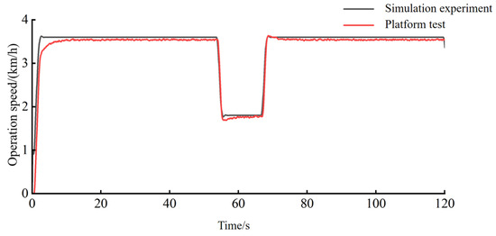
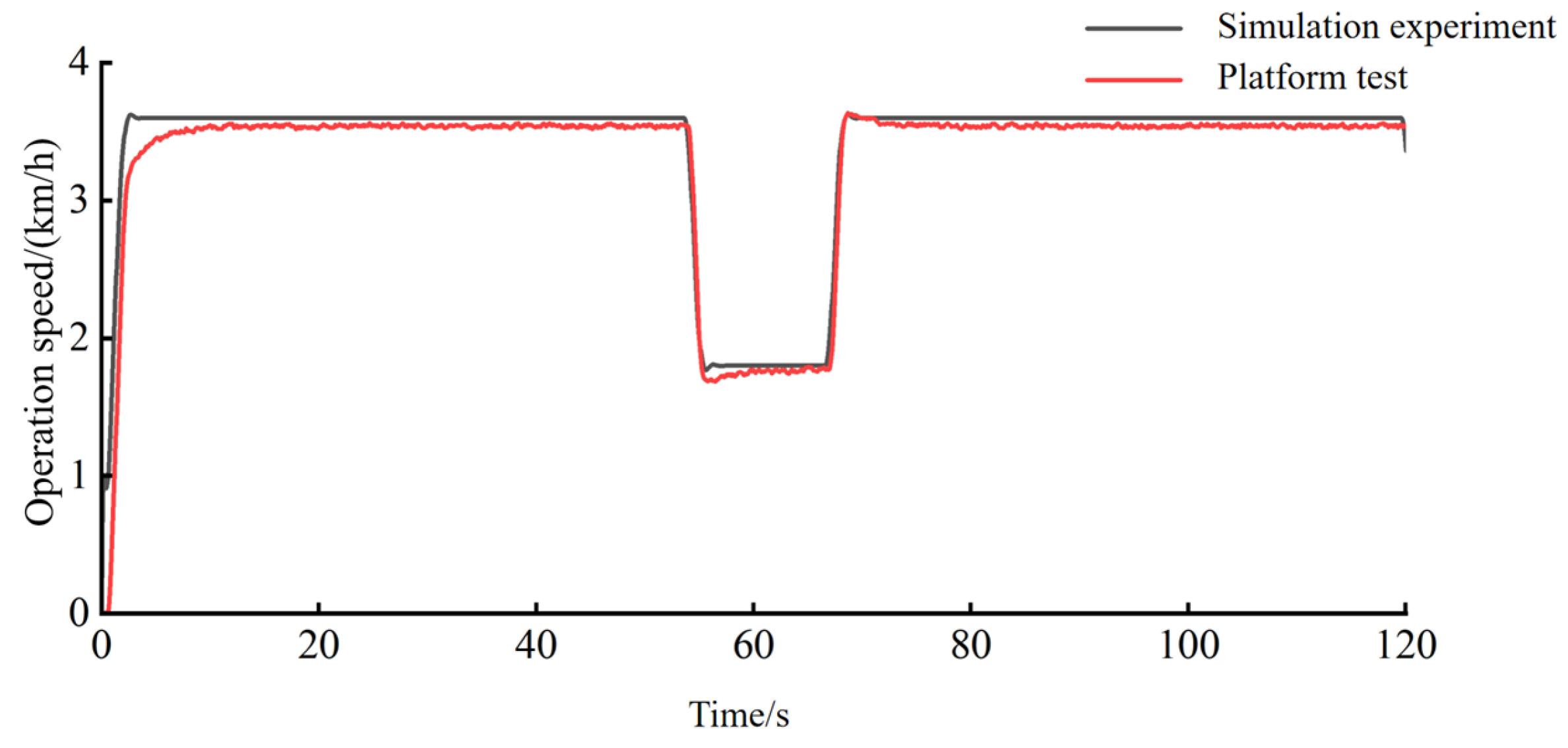
As illustrated in Figure 21, the vehicle speeds in both the simulation and platform tests meet the cyclic operational requirements of the sprayer, with the two velocity curves exhibiting high consistency. Notably, the simulation velocity is slightly higher and the profile is smoother than that of the platform test. This discrepancy is attributed to the more complex resistance patterns encountered in the physical platform test compared to the idealized simulation environment.
Figure 21.
Test results of the spraying operation speed.
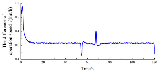
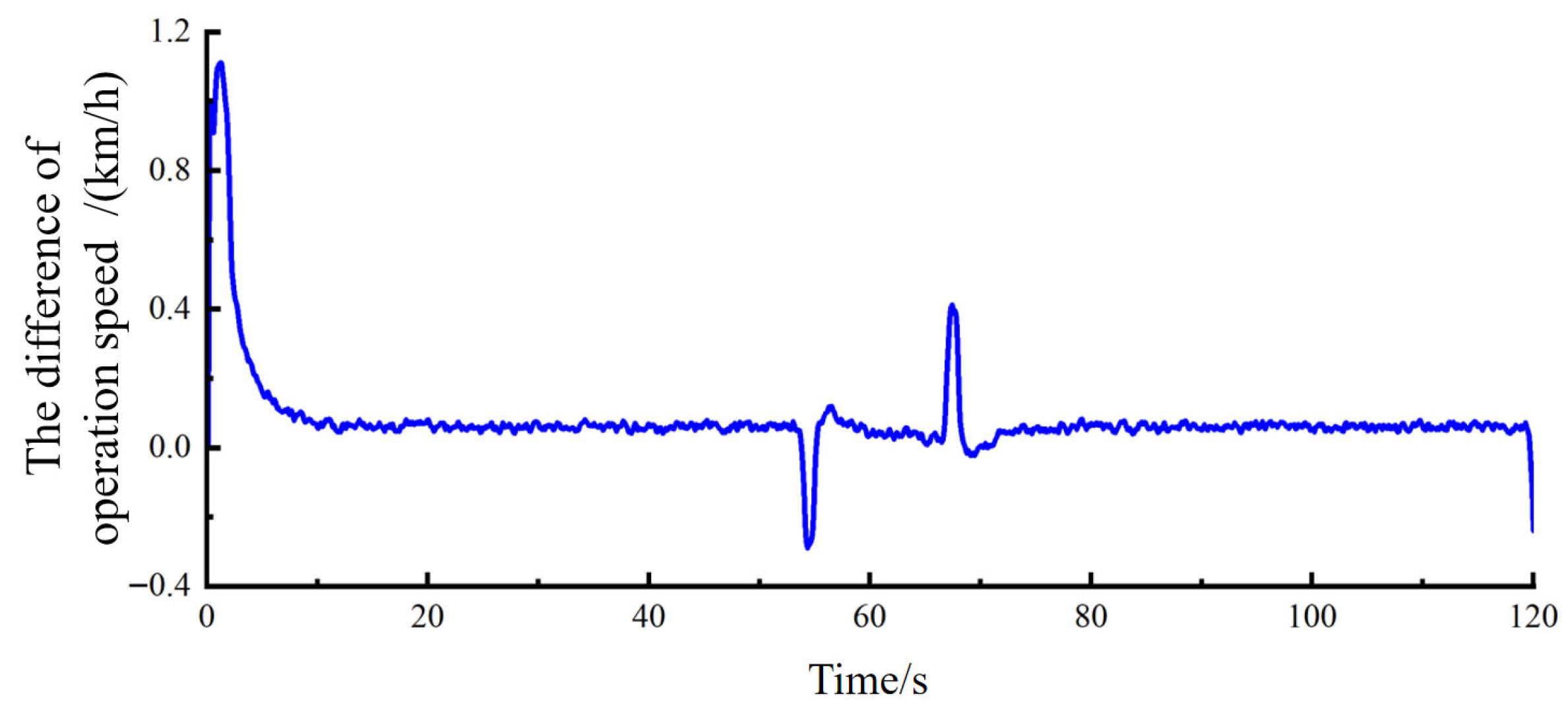
Furthermore, due to the signal transmission latency inherent in the test platform, a relatively large velocity deviation between the simulation and test platform is observed during the initial acceleration phase, as shown in Figure 22. According to the velocity deviation data presented in Figure 22, the differences are more pronounced during acceleration and deceleration, reaching a maximum value of 1.11 km/h. Conversely, the velocity deviation remains minimal when the operating speed stabilizes. Comprehensive analysis indicates that the mean velocity deviation throughout the entire process is 0.079 km/h, with a mean velocity error of only 3.1%.
Figure 22.
The speed difference between simulation tests and platform tests.
3.2.2. Test Results of Battery SOC During Cyclic Operation
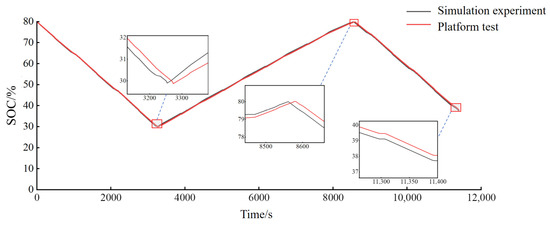
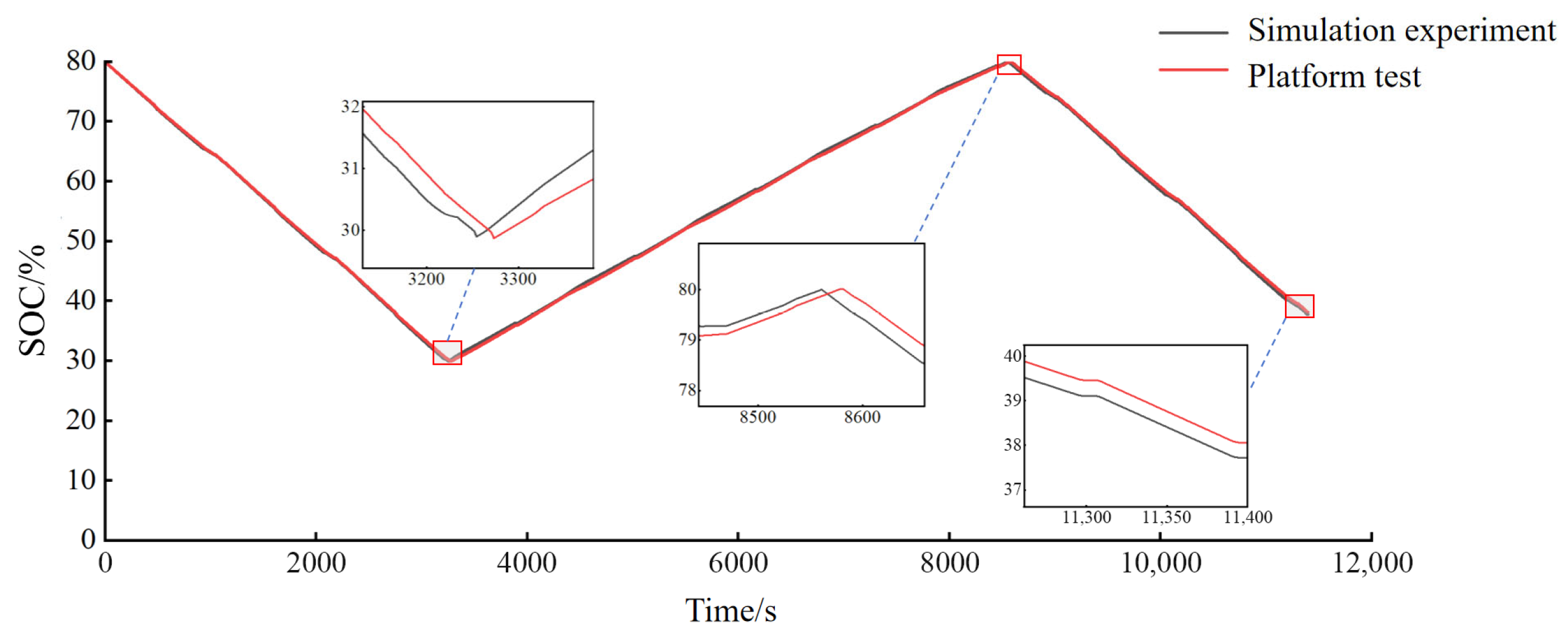
According to the battery State of Charge (SOC) test results for cyclic operation shown in Figure 23, the SOC levels in the simulation and platform tests remain essentially consistent throughout the entire operational process. The duration required for the battery SOC to decrease to the range extender (RE) activation threshold for the first time is 3250 s in the simulation and 3267 s on the test platform, representing a relative error of 0.52%. Specifically, the RE response time in the simulation is 4.1 s, while the response time on the test platform is 7.1 s (including engine startup duration). Consequently, the figure clearly shows that the minimum SOC reached on the test platform is slightly lower at 29.85%, compared to 29.90% in the simulation. Similarly, the RE response on the test platform is slower than that in the simulation when the SOC first reaches the deactivation threshold. At the conclusion of the cyclic operation, the SOC values for the platform test and simulation are 38.09% and 37.71%, respectively, with a discrepancy of 0.38%.
Figure 23.
The result of electric quantity test for cycle operation.
3.2.3. Engine Fuel Consumption Test Results
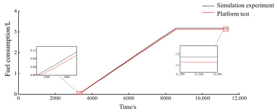
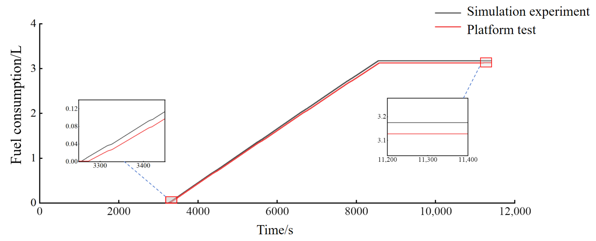
As illustrated in Figure 24, the fuel consumption curves for the simulation and platform test exhibit high consistency. Specifically, the fuel consumption in the simulation begins to increase at 3254.1 s, while that of the platform test starts at 3273.1 s, both following an identical increasing trajectory. Upon completion of the cyclic operation test, the total fuel consumption for the platform test and simulation are 3.13 L and 3.18 L, respectively, representing a discrepancy of only 1.6%.
Figure 24.
Fuel consumption test results of cycle operation.
3.2.4. Comparative Analysis of EMS Experimental Results
As presented in Table 5, the platform experimental data for the three EMS strategies are compared and analyzed. The PSO-optimized fuzzy control EMS yields an equivalent fuel consumption of 3.65 kg, maintaining the highest fuel economy among the three evaluated strategies. For the multi-point power follower EMS, the equivalent fuel consumption values in the simulation and platform tests are 4.01 kg and 4.07 kg, respectively, resulting in a relative error of 1.5%. For the standard fuzzy control EMS, the equivalent fuel consumption for the simulation and platform testing are 3.87 kg and 3.92 kg, respectively, with a relative error of 1.3%. Regarding the PSO-optimized fuzzy control EMS, the simulation and platform results are 3.68 kg and 3.65 kg, respectively, yielding a relative error of only 0.8%. All errors remain within acceptable limits, thereby fully validating the reliability of the simulation platform and the feasibility of the proposed EMS strategies.
Table 5.
Comparison test results of EMSs.
3.3. Vehicle Testing
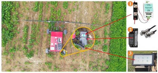
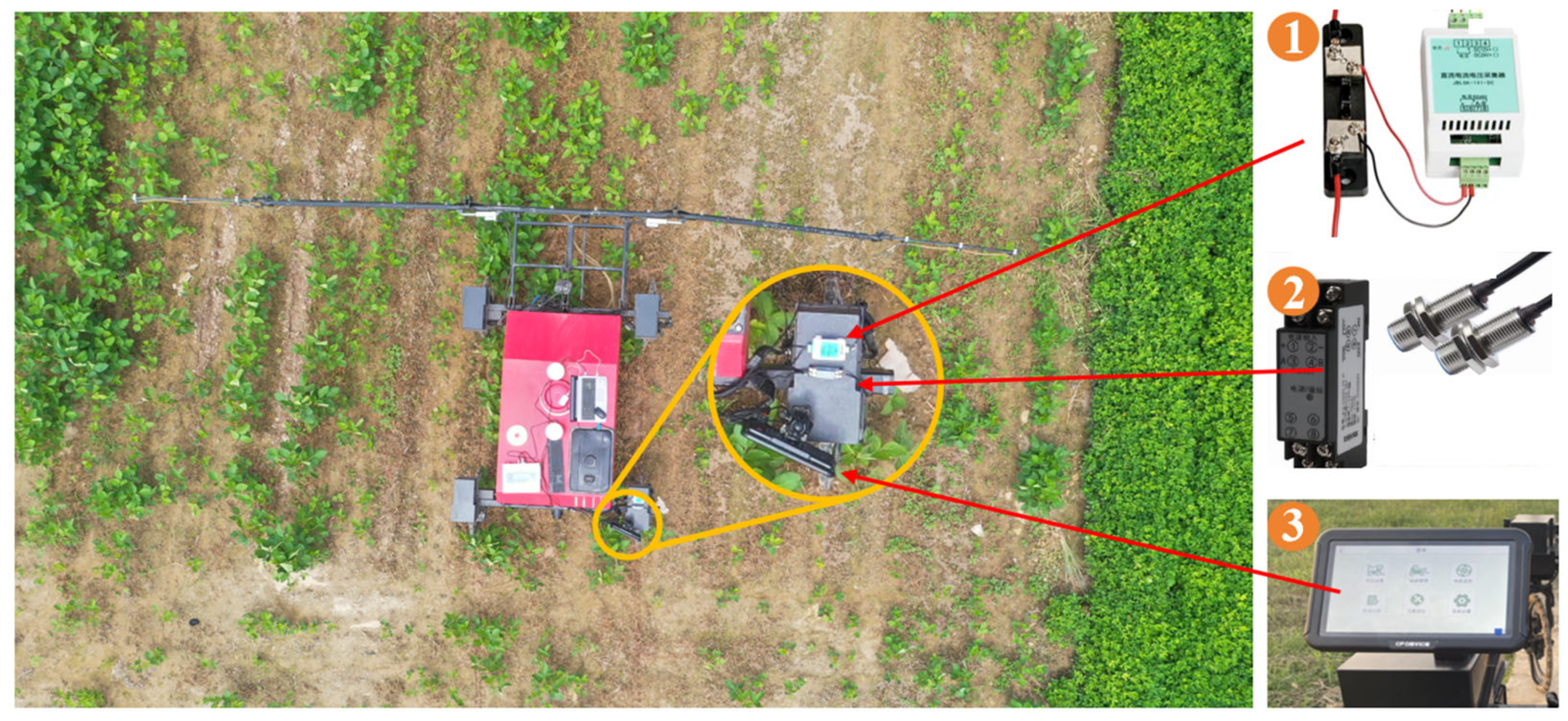
To verify the rationality and accuracy of the simulation platform and EMS, the operation of the entire vehicle was studied through field spraying tests under the premise of meeting the agronomic requirements of spraying operations. The field test is shown in Figure 25. The main steps of the test are as follows:
Figure 25.
Field trials. Note: 1—Current and voltage sensor; 2—Rotational speed sensor; 3—Host computer.
- (1)
- Before the test, install and debug components such as sensors, including current and voltage acquisition modules, speed sensors, etc.
- (2)
- Through the satellite positioning interface of the spraying machine control system, mark the operation area, complete the path planning of the spraying operation through the field management interface, and obtain the operation route of the spraying machine. In the operation management interface, the operation speed of the spraying machine, the power of the water pump, etc. can be set.
- (3)
- Conduct field operations, enter the unmanned driving mode, first obtain the various data of the motor through the motor monitoring panel of the control panel, and then obtain the data of the driving motor speed, current, voltage, battery power, etc. of the spraying machine during operation through the upper computer for comparison and verification.
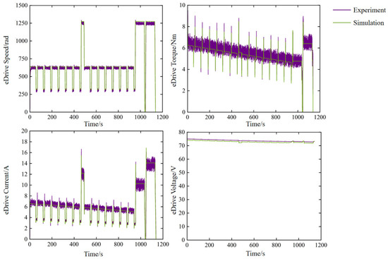
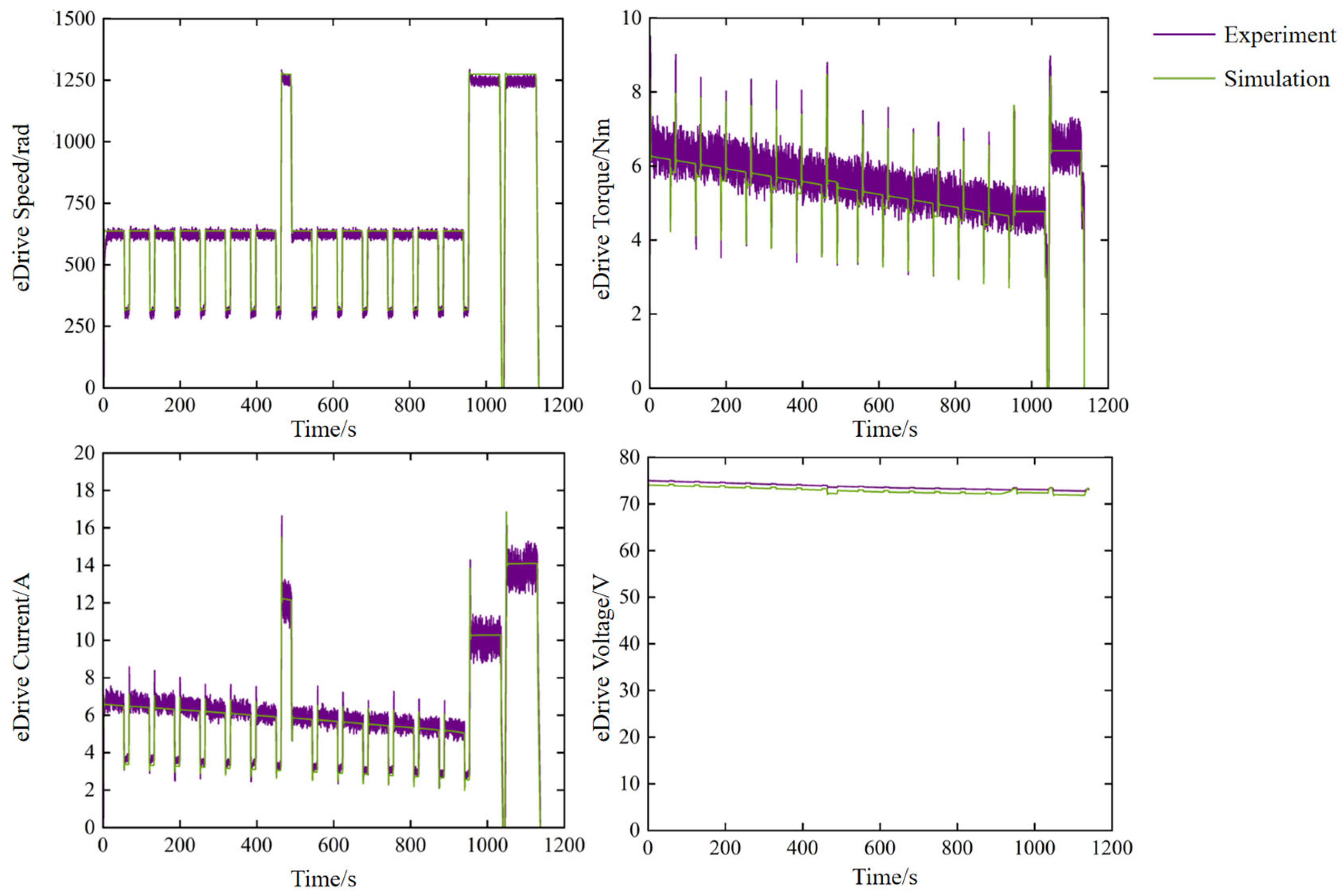
The collected field data were compared and analyzed alongside the simulation data, with the findings presented in Figure 26. The time depicted in the figure aligns with the first cycle of the test data. The motor speed curve reveals that the difference between the simulation and field test speeds is minimal. The speed during the field test varies noticeably because of the soil’s complexity and variability. From the motor torque curve, it can also be seen that due to the influence of factors such as terrain changes in actual operation, the actual torque will have large fluctuations. From examining the voltage and current curves, the voltage curve exhibits a high level of agreement with the simulation data. Because of the influence of components and electrical devices, as well as the soil’s complexity and variability, the current differs from the anticipated result, but it stays within an acceptable range.
Figure 26.
Field test results.
In the first cycle, power consumption led to a 16.60% decrease in SOC during the field test and a 16.95% decrease in the simulation. The error in power consumption remained within a reasonable range, further validating the feasibility of the PSO-fuzzy EMS. The actual test results and simulation data show a high level of agreement, indicating that this simulation model is appropriate for use in vehicle testing.
4. Conclusions
This paper takes the self-developed 3WPZ-300 unmanned range-extended sprayer as the research object. Aiming at the problems of poor fuel economy and insufficient dynamic response capability of the range extender under complex agronomic environments, a co-simulation platform based on AVL-CRUISE and MATLAB/Simulink is established. The energy variation laws of the range-extended sprayer under different energy management strategies are investigated, and simulation and platform tests are carried out for verification. The main conclusions are as follows:
- (1)
- An improved energy management model for multi-condition cyclic operation of the range-extended sprayer is established based on AVL-CRUISE and MATLAB/Simulink. Considering the influence of continuous variation in spray liquid mass on the vehicle demand power during spraying operations, a power model of the spray system with mass-resistance wheel-side coupling characteristics is constructed. This realizes the co-simulation of the intermittent operation of the water pump, dynamic variation of tank mass, and real-time coupling of wheel-side resistance. According to the agronomic requirements of spray operations, a mathematical model of the complete range-extended sprayer is established. The performance parameters of the engine, generator, power battery, wheel-side motor, and other components are measured, and the co-simulation models of the entire vehicle, engine, generator, power battery, and spray system are constructed.
- (2)
- A fuzzy control energy management strategy optimized by the particle swarm optimization (PSO) algorithm is proposed, which significantly improves fuel economy. Simulation results show that under cyclic operating conditions, the comprehensive fuel consumption of the PSO-optimized fuzzy control energy management strategy is 3.68 kg, representing an improvement in fuel economy of 4.90% compared with the conventional fuzzy control strategy and 8.23% compared with the multi-point power-following strategy. The PSO algorithm performs global optimization on the membership functions of the fuzzy controller, enabling the engine to operate within the optimal fuel consumption range for a long time and avoiding extra fuel consumption caused by frequent switching of operating points.
- (3)
- An energy management test platform for the range-extended sprayer is built and verified through experiments. Platform test results show that the difference in electricity consumption between platform tests and simulation tests is 0.38%, and the difference in fuel consumption is 1.6%. The relative errors between platform tests and simulation tests in equivalent fuel consumption for the multi-point power-following EMS, fuzzy control EMS, and PSO-optimized fuzzy control EMS are 1.5%, 1.3%, and 0.8%, respectively, all within a reasonable range, which further verifies the reliability of the simulation platform and the feasibility of the energy management strategies. The three strategies exhibit good generalization ability under different operating conditions of the sprayer. Under light-load/low-speed conditions, pure electric mode can be used to avoid inefficient engine operation; under high-intensity operations such as heavy-load/climbing conditions, battery-assisted power supply can be employed to meet peak power demand.
The above research contents and results provide theoretical basis and technical support for the optimization of energy management strategies and the co-simulation method of energy management for range-extended sprayers.
Author Contributions
Conceptualization, H.L. and G.C.; methodology, Y.G. and T.Y.; software, Y.G. and T.Y.; validation, G.C. and S.C.; investigation, Y.G. and T.Y.; resources, H.L.; data curation, Y.G. and T.Y.; writing—original draft preparation, Y.G.; writing—review and editing, H.L. and G.C.; visualization, G.C. and S.C.; supervision, H.L. and G.C.; project administration, H.L. All authors have read and agreed to the published version of the manuscript.
Funding
This research was funded by the Agricultural Scientific Research System Project of the Ministry of Finance (CARS-04) and the Science and Technology Research Project of Henan Province (242102111175).
Institutional Review Board Statement
Not applicable.
Data Availability Statement
The original contributions presented in this study are included in the article. Further inquiries can be directed to the corresponding author.
Conflicts of Interest
The authors declare no conflicts of interest.
References
- Mantoam, E.J.; Angnes, G.; Mekonnen, M.M.; Romanelli, T.L. Energy, carbon and water footprints on agricultural machinery. Biosyst. Eng. 2020, 198, 304–322. [Google Scholar] [CrossRef] [Scilit]
- Zhao, Y.; Xu, L.; Zhao, C.; Xu, H.; Yan, X. Research on Energy Management Strategy for Hybrid Tractors Based on DP-MPC. Energies 2024, 17, 3924. [Google Scholar] [CrossRef] [Scilit]
- Moreda, G.P.; Muñoz-García, M.A.; Barreiro, P.J.E.C. High voltage electrification of tractor and agricultural machinery–A review. Energy Convers. Manag. 2016, 115, 117–131. [Google Scholar] [CrossRef] [Scilit]
- Xu, G.W.; Song, Y.M.; Qiu, X.Y.; Liang, J.M.; Gao, Q.; Li, H. Matching Design and Test of Power System for Electric Self-propelled Crawler Chassis of Orchard. J. Agric. Mech. Res. 2022, 44, 251–255. [Google Scholar] [CrossRef]
- Zhou, L.; Hu, C.; Chen, Y.; Guo, P.; Zhang, L.; Liu, J.; Chen, Y. Research and Experiment on Cruise Control of a Self-Propelled Electric Sprayer Chassis. Agriculture 2024, 14, 902. [Google Scholar] [CrossRef] [Scilit]
- Fan, X.; Chai, X.; Zhou, J.; Sun, T. Deep learning based weed detection and target spraying robot system at seedling stage of cotton field. Comput. Electron. Agric. 2023, 214, 108317. [Google Scholar] [CrossRef] [Scilit]
- Kaliniewicz, Z.; Lipiński, A.; Markowski, P.; Szczyglak, P.; Lipiński, S. The influence of selected operating parameters of a field sprayer on boom stability. Comput. Electron. Agric. 2024, 219, 108787. [Google Scholar] [CrossRef] [Scilit]
- Bayat, A.; İtmeç, M.; Özlüoymak, Ö.B. Development and assessment of a novel servo-controlled spraying system for real time adjustment of the orientation angle of the nozzles of a boom sprayer. Pest Manag. Sci. 2023, 79, 4439–4450. [Google Scholar] [CrossRef] [Scilit]
- Cui, L.F.; Xue, X.Y.; Ding, S.M.; Le, F.X. Development of a DSP-based electronic control system for the active spray boom suspension. Comput. Electron. Agric. 2019, 166, 105024. [Google Scholar] [CrossRef] [Scilit]
- Patel, M.K.; Praveen, B.; Sahoo, H.K.; Patel, B.; Kumar, A.; Singh, M.; Rajan, P. An advance air-induced air-assisted electrostatic nozzle with enhanced performance. Comput. Electron. Agric. 2017, 135, 280–288. [Google Scholar] [CrossRef] [Scilit]
- Yang, H.; Liu, D.; Zhou, J.; Wang, Z.; Wang, X. Research progress of extended range electric tractor. J. Chin. Agric. Mech. 2022, 43, 118. [Google Scholar] [CrossRef]
- Liu, M.; Li, Y.; Xu, L.; Wang, Y.; Zhao, J. General modeling and energy management optimization for the fuel cell electric tractor with mechanical shunt type. Comput. Electron. Agric. 2023, 213, 108178. [Google Scholar] [CrossRef] [Scilit]
- Zhao, J.H.; Xu, L.Y.; Liu, E.Z.; Meng, T. Design of Drive System for Range-extended Electric Tractor. J. Agric. Mech. Res. 2018, 40, 236–240. [Google Scholar] [CrossRef]
- Wang, L.; Wang, S.; Song, Z. Research on Control Strategy and Startup Method of Extended-Range Electric Tractor. J. Agric. Mach. Sci. 2018, 49, 486–491. [Google Scholar] [CrossRef]
- Wu, Z.; Wang, J.; Xing, Y.; Li, S.; Yi, J.; Zhao, C. Energy Management of Sowing Unit for Extended-Range Electric Tractor Based on Improved CD-CS Fuzzy Rules. Agriculture 2023, 13, 1303. [Google Scholar] [CrossRef] [Scilit]
- Zhou, R.; Wang, L.; Deng, X.; Su, C.; Fang, S.; Lu, Z. Research on Energy Distribution Strategy of Tandem Hybrid Tractor Based on the Pontryagin Minimum Principle. Agriculture 2024, 14, 440. [Google Scholar] [CrossRef] [Scilit]
- Farhadi, P.; Golmohammadi, A.; Sharifi, A.; Shahgholi, G. Potential of three-dimensional footprint mold in investigating the effect of tractor tire contact volume changes on rolling resistance. J. Terramech. 2018, 78, 63–72. [Google Scholar] [CrossRef] [Scilit]
- Landry, H.; Wolf, T.M. An investigation of airflow patterns created by high-clearance sprayers during field operations. Can. Biosyst. Eng. J. 2019, 61, 2.01–2.12. [Google Scholar] [CrossRef] [Scilit]
- Mao, Y.; Wu, Y.; Yan, X.; Liu, M.; Xu, L. Simulation and experimental research of electric tractor drive system based on Modelica. PLoS ONE 2022, 17, e0276231. [Google Scholar] [CrossRef] [Scilit]
- Xu, Y.; Zhang, H.; Yang, Y.; Zhang, J.; Yang, F.; Yan, D.; Yang, H.; Wang, Y. Optimization of energy management strategy for extended range electric vehicles using multi-island genetic algorithm. J. Energy Storage 2023, 61, 106802. [Google Scholar] [CrossRef] [Scilit]
- Yu, Y.; Hao, S.; Guo, S.; Tang, Z.; Chen, S. Motor Torque Distribution Strategy for Different Tillage Modes of Agricultural Electric Tractors. Agriculture 2022, 12, 1373. [Google Scholar] [CrossRef] [Scilit]
- Deng, X.; Sun, H.; Lu, Z.; Cheng, Z.; An, Y.; Chen, H. Research on dynamic analysis and experimental study of the distributed drive electric tractor. Agriculture 2022, 13, 40. [Google Scholar] [CrossRef] [Scilit]
- Liu, Z.; Zhang, G.; Chu, G.; Niu, H.; Zhang, Y.; Yang, F. Design matching and dynamic performance test for an HST-based drive system of a hillside crawler tractor. Agriculture 2021, 11, 466. [Google Scholar] [CrossRef] [Scilit]
- Yin, B.; Yun, L.; Xie, X.; Wang, J.; Huang, Y. Optimized fuzzy control energy management strategy for hybrid tractors considering working conditions adaptation. J. Mech. Sci. Technol. 2025, 39, 3443–3455. [Google Scholar] [CrossRef] [Scilit]
- Lu, L.; Zhao, H.; Liu, X.; Sun, C.; Zhang, X.; Yang, H. MPC-ECMS energy management of extended-range vehicles based on LSTM multi-signal speed prediction. Electronics 2023, 12, 2642. [Google Scholar] [CrossRef] [Scilit]
- He, H.; Xiong, R.; Fan, J. Evaluation of lithium-ion battery equivalent circuit models for state of charge estimation by an experimental approach. Energies 2011, 4, 582–598. [Google Scholar] [CrossRef] [Scilit]
- Deng, L.; Radzi, M.A.M.; Shafie, S.; Hassan, M.K. Optimization of fuel cell switching control based on power following strategy in fuel cell hybrid electrical vehicle. Int. J. Renew. Energy Dev. 2025, 14, 299–310. [Google Scholar] [CrossRef] [Scilit]
- Lu, L.; Zhao, H.; Xv, F.; Luo, Y.; Chen, J.; Ding, X. GA-LSTM speed prediction-based DDQN energy management for extended-range vehicles. Energy AI 2024, 17, 100367. [Google Scholar] [CrossRef] [Scilit]
- Rivera-Barrera, J.P.; Muñoz-Galeano, N.; Sarmiento-Maldonado, H.O. SoC estimation for lithium-ion batteries: Review and future challenges. Electronics 2017, 6, 102. [Google Scholar] [CrossRef] [Scilit]
- Beşkardeş, A.; Hameş, Y.; Kaya, K. A comprehensive review on fuzzy logic control systems for all, hybrid, and fuel cell electric vehicles. Soft Comput. 2024, 28, 8183–8221. [Google Scholar] [CrossRef] [Scilit]
- Parkar, O.; Snyder, B.; Rahi, A.; Anwar, S. Modified Particle Swarm Optimization Based Powertrain Energy Management for Range Extended Electric Vehicle. Energies 2023, 16, 5082. [Google Scholar] [CrossRef] [Scilit]
- Shi, D.; Rong, X.; Wang, S.; Chen, L. Fuzzy Adaptive Equivalent Consumption Minimization Strategy for Hybrid Electric Vehicle Based on Power Ratio. J. Xi’an Jiaotong Univ. 2022, 56, 12–21. [Google Scholar] [CrossRef]
- Xiao, B.; Ruan, J.; Yang, W.; Walker, P.D.; Zhang, N. A review of pivotal energy management strategies for extended range electric vehicles. Renew. Sustain. Energy Rev. 2021, 149, 111194. [Google Scholar] [CrossRef] [Scilit]
- Gao, F.; Liu, J.; Yang, D.; Han, G.; Qi, F.; Liu, Q. Prediction of the Remaining Useful Life of PEMFC Based on Particle Swarm Optimization Algorithm Combined with Improved Echo State Network. J. Northwest. Polytech. Univ. 2025, 43, 478–487. [Google Scholar] [CrossRef] [Scilit]
- Oubelaid, A.; Albalawi, F.; Rekioua, T.; Ghoneim, S.S.M.; Taib, N.; Abdelwahab, S.A.M. Intelligent Torque Allocation Based Coordinated Switching Strategy for Comfort Enhancement of Hybrid Electric Vehicles. IEEE Access 2022, 10, 58097–58115. [Google Scholar] [CrossRef] [Scilit]

Disclaimer/Publisher’s Note: The statements, opinions and data contained in all publications are solely those of the individual author(s) and contributor(s) and not of MDPI and/or the editor(s). MDPI and/or the editor(s) disclaim responsibility for any injury to people or property resulting from any ideas, methods, instructions or products referred to in the content. |
© 2026 by the authors. Licensee MDPI, Basel, Switzerland. This article is an open access article distributed under the terms and conditions of the Creative Commons Attribution (CC BY) license.