


Abstract
In response to the problems of low fertilizer utilization efficiency and increased environmental risks caused by the widespread adoption of band fertilization during sunflower cultivation, a sunflower hole fertilization planter was designed according to the agronomic requirements of the major sunflower-producing regions in China. First, the key components of the planter, including an electrically driven fertilizer metering device, an intermittent fertilization mechanism, and a fertilization system for seed holes, were designed. Subsequently, the effects of the target fertilizer application rate per hole (A), baffle opening time (B), and operating speed (C) on hole spacing error (Y1) and the coefficient of variation in fertilizer application rate per hole (Y2) were analyzed using the Box–Behnken response surface methodology, and the optimal operating parameters were obtained. Finally, experiments were conducted under the optimal operating parameters, namely a target fertilizer application rate per hole of 6.6 g, a baffle opening time of 87 ms, and an operating speed of 4.4 km/h. The results showed that the hole spacing error was 1.78%, while the coefficient of variation in fertilizer application rate per hole was 15.87%. The sunflower planter developed in this study was capable of satisfying the agronomic requirements of sunflower hole fertilization operations and provides a reference for the design and optimization of sunflower hole fertilization systems.
1. Introduction
Sunflower is one of the most important oil and economic crops in China [1]. Owing to its excellent characteristics, including drought tolerance and saline–alkali tolerance, it is widely cultivated in regions such as Xinjiang and Inner Mongolia [2,3]. Its seeds are rich in oil and protein and are extensively used in edible oil processing and the food industry [4,5]. At present, band fertilization is commonly adopted in sunflower cultivation in China [6]. Although this method is convenient to implement and offers relatively high operational efficiency, it is prone to problems such as low fertilizer utilization efficiency, high production costs, and increased environmental risks [7,8], making it difficult to satisfy the agronomic requirements of modern agriculture for efficient and precise fertilization [9,10,11]. Previous studies have demonstrated that synchronous hole fertilization during sowing can reduce fertilizer input by improving the spatial distribution of fertilizer. Meanwhile, placing fertilizer at an appropriate depth and position relative to the seed facilitates root nutrient uptake and crop growth, contributing to uniform seedling establishment and improved crop productivity [12,13,14]. Therefore, the development of a precision hole fertilization planter coordinated with the sowing process is of great significance for improving the quality of sunflower fertilization operations and promoting the green and efficient development of the sunflower industry.
With the development of precision agriculture, researchers worldwide have conducted extensive studies on hole fertilization planters for different crops and operating conditions. According to their working principles, fertilization mechanisms can be classified into fluted-wheel, cavity-disc, centrifugal, and intermittent types. The fluted-wheel fertilization mechanism quantitatively delivers fertilizer from the fertilizer box by means of a rotating fluted wheel. Liao et al. [15] designed a mechanical hole fertilization device and determined the optimal parameter combination for hole-forming performance through orthogonal experiments. Shi et al. [16] investigated the fertilizer discharge performance of a fluted-wheel fertilizer metering device under different control strategies using EDEM simulation to address the issue of discharge stability in a precision variable-rate fertilizer applicator for rice and wheat. Qi et al. [17] designed a directional deep fertilization device for maize and analyzed the mechanical characteristics of the fertilizer discharge process based on Adams–EDEM coupled simulation, achieving synchronous sowing and fertilization with good seed–fertilizer synchronization. Pan et al. [18] developed a synchronous hole fertilization device for maize sowing based on STM32 and obtained the optimal operating parameter combination using the Box–Behnken response surface method. The fluted-wheel structure is simple and convenient for discharge rate adjustment; however, due to its structural characteristics, fertilizer leakage and unstable fertilizer discharge are likely to occur during the metering process, resulting in reduced fertilizer utilization efficiency [19].
The cavity-disc fertilization mechanism performs fertilizer filling and discharge through uniformly distributed fertilizer cavities arranged on a rotating disc. Liu et al. [20,21] designed a precision hole fertilization device with a cavity-disc structure, in which the fertilizer application rate was controlled by adjusting the relative angle between the stator and rotor, resulting in stable metering performance. Du et al. [22] proposed an inclined trapezoidal-hole quantitative hole fertilizer metering device, in which fertilizer was rapidly discharged under the combined action of airflow and centrifugal force. However, the device relies on an auxiliary pneumatic system to discharge fertilizer from the cavities, increasing system complexity and energy consumption. Residual fertilizer may remain in the cavities after discharge, affecting the accuracy and consistency of per-hole fertilizer dosage during long-term operation. In addition, the compact structure increases installation difficulty and may affect integration with existing sunflower planters and fertilizer placement.
The centrifugal fertilization mechanism utilizes a rotating disc to drive fertilizer particles in circular motion and eject them tangentially under centrifugal force. Shan et al. [23,24] proposed a rotary centrifugal fertilization mechanism in which fertilizer particles were carried by the blades of a fertilizer disc in circular motion and entered the fertilizer delivery tube tangentially within the discharge zone to achieve quantitative fertilizer application. Du et al. [25] designed a high-speed hole fertilization device and investigated the effects of fertilizer disc rotational speed and cavity structure on hole-forming performance. The results indicated that, under high-speed operating conditions, the increased impact velocity of fertilizer particles upon contact with the ground intensified particle scattering and bouncing, resulting in a significant increase in hole length. Moreover, the synchronization between fertilizer placement and seed placement, namely applying fertilizer at the corresponding position according to seed delivery, is not considered in the design of this type of mechanism.
The intermittent fertilization mechanism converts a continuous fertilizer flow into intermittent fertilizer clusters by incorporating an opening–closing device within the fertilizer conveying process. Wu et al. [26] designed a duckbill-valve hole-forming precision fertilization system for a no-tillage planter and determined the optimal combination of forward speed, rotation angle, and installation height. Li et al. [27] developed a seed-hole fertilization control system based on STM32, in which continuous fertilizer flow was converted into intermittent fertilizer clusters according to seed-falling signals and applied near the seeds. The intermittent fertilization mechanism can effectively synchronize fertilizer discharge with seed placement and improve fertilizer application accuracy while avoiding fertilizer leakage and improving fertilizer discharge stability. However, its overall structure is relatively complex and places higher requirements on the response speed and control accuracy of the electronic control system.
To address the above issues, the overall structure of a sunflower hole fertilization planter was designed in accordance with the operational requirements of sunflower hole fertilization. The design mainly included key components such as an intermittent fertilization mechanism, an electrically driven fertilizer metering device, and a seed-hole fertilization system. Furthermore, field experiments were conducted to verify the operational performance of the developed planter.
2. Materials and Methods
2.1. Overall Structure and Working Principle of the Machine
2.1.1. Agronomic Requirements for Sunflower Cultivation
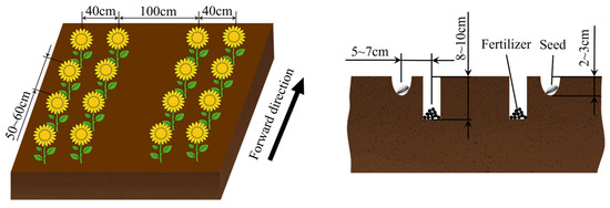
According to the local standard DB 15/T 3577-2024 [28] of the Inner Mongolia Autonomous Region, sunflower is cultivated using a wide–narrow row planting pattern, with a wide row spacing of 100 cm and a narrow row spacing of 40 cm. The plant spacing is 50–60 cm, the sowing depth is 2–3 cm, and approximately 1 cm of sand is used to cover and seal the seed hole. The fertilizer is generally applied at a depth of 8–10 cm, with a horizontal distance of 5–7 cm between the fertilizer and the seed to avoid seed injury and promote nutrient uptake by the root system, as shown in Figure 1.
Figure 1.
Schematic Diagram of Agronomic Requirements for Sunflower Cultivation.
2.1.2. Overall Structure of the Machine
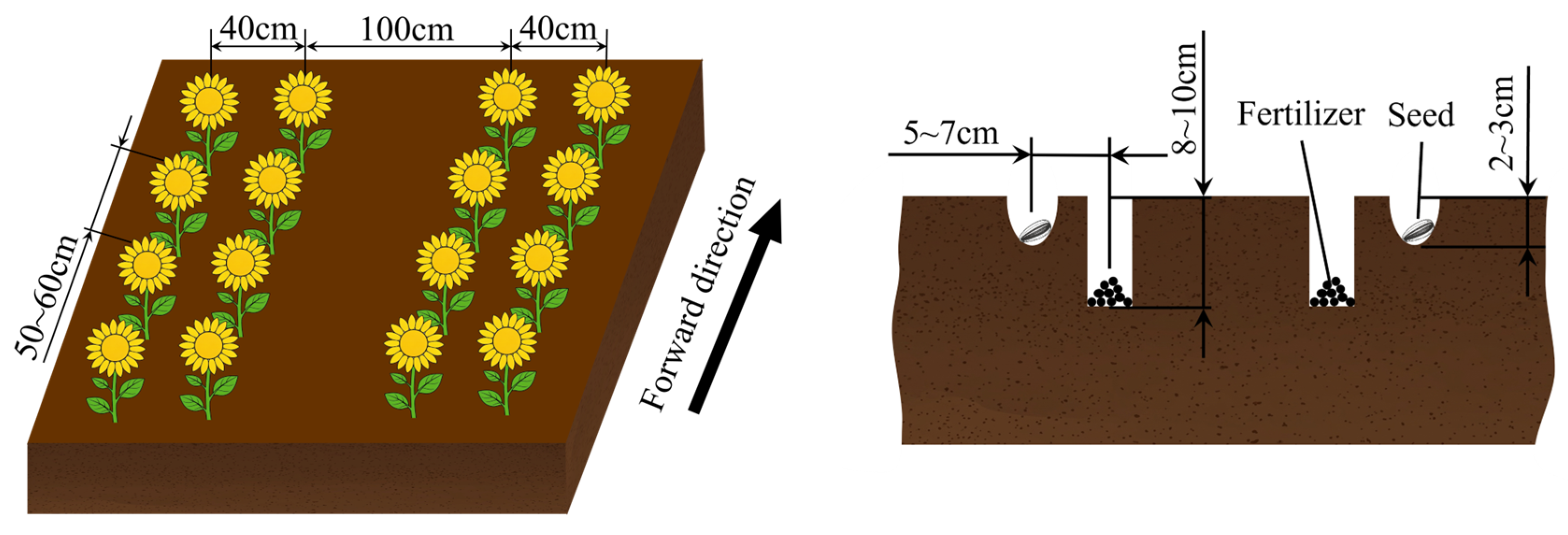
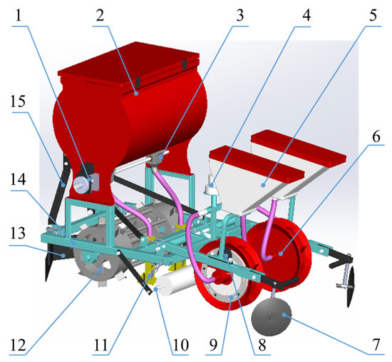
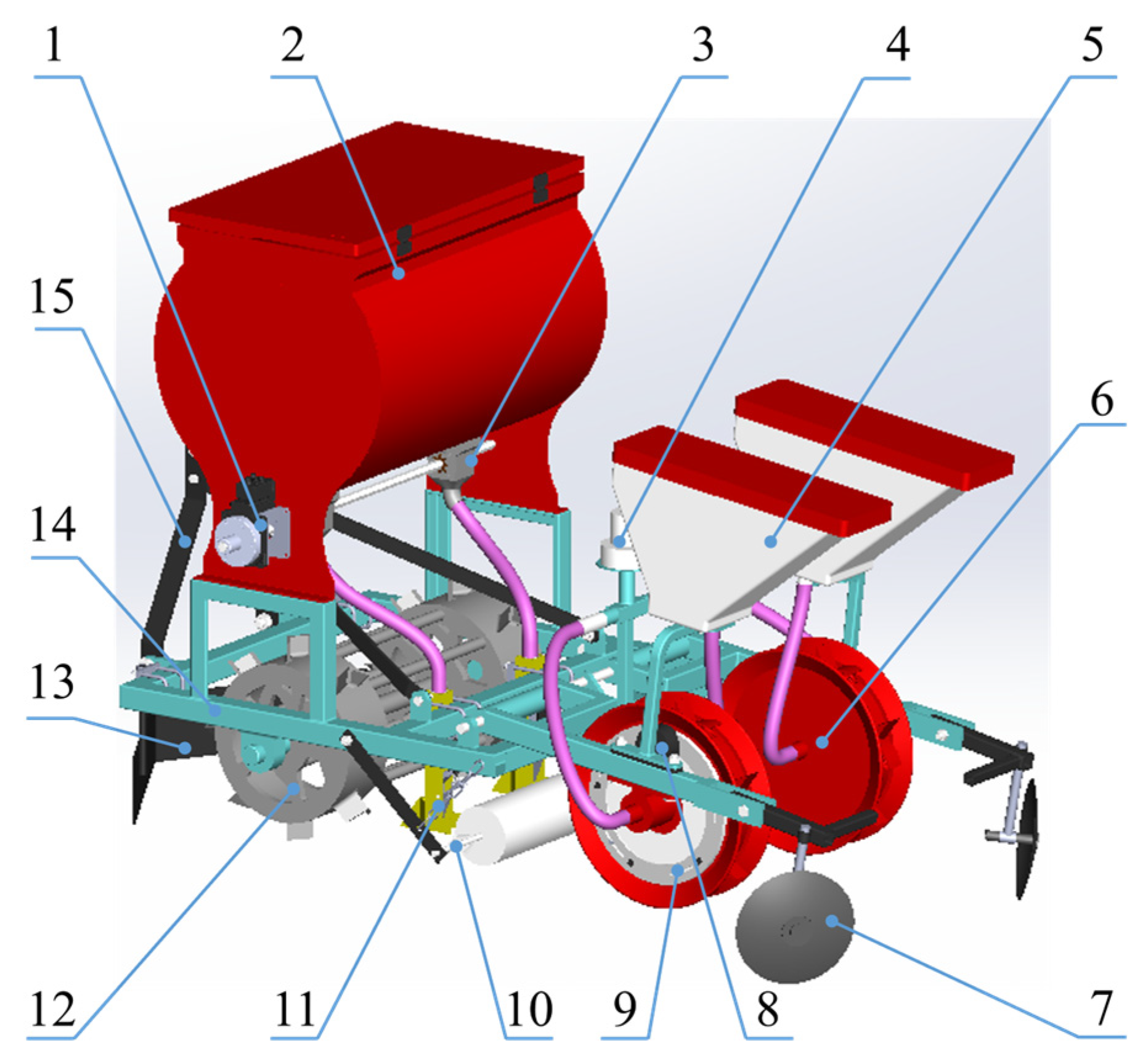
The sunflower hole fertilization planter mainly consists of a sowing unit, a fertilization unit, and an auxiliary operation unit. The sowing unit is composed of a seed box, an air pump, a duckbill seed metering device, and other components, and is used to complete seed pickup, conveying, and placement. The fertilization unit consists of an electrically driven fertilizer metering device, an intermittent fertilization mechanism, a seed-hole fertilization system, and other components, and is used to achieve quantitative fertilizer conveying and targeted fertilizer application. The auxiliary operation unit mainly includes a hitch frame, frame, land levelling plate, ground wheel, film-laying device, and soil-covering disc, which are used to provide machine support, traction, and auxiliary field operations. The overall structure of the machine is shown in Figure 2.
Figure 2.
Structural Schematic of the Sunflower Hole Fertilization Planter: 1. Servo motor; 2. Fertilizer box; 3. Fertilizer metering device; 4. Air pump; 5. Seed box; 6. Duckbill seed metering device; 7. Soil-covering disc; 8. Hall sensor; 9. Speed measuring disc; 10. Film-laying device; 11. Intermittent fertilization mechanism; 12. Ground wheel; 13. Land levelling plate; 14. Frame; 15. Hitch frame.
The seed box is used to store the seeds required during the sowing process. The air pump provides a stable air source during operation and works in conjunction with the duckbill seed metering device to pick up and convey seeds to the designated sowing position. The duckbill seed metering device is the core component of the sowing unit and rolls along the ground as the planter advances, achieving seed placement through the opening and closing actions of the duckbill valve. The electrically driven fertilizer metering device adjusts the rotational speed of the fertilizer metering wheel in real time according to the operating speed, thereby controlling the fertilizer application rate. The intermittent fertilization mechanism employs a linear motor to drive the baffle for intermittent fertilizer application. The seed-hole fertilization system is mainly used for operating speed detection and seed–fertilizer position control. To meet the requirements of precision sowing and simultaneous fertilization in sunflower production, the overall structure of the planter was designed with reference to existing sunflower planters, and the main technical parameters were determined considering the requirements of mechanized sunflower production, as shown in Table 1.
Table 1.
Main Technical Parameters of the Planter.
2.1.3. Working Principle
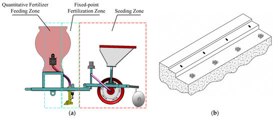
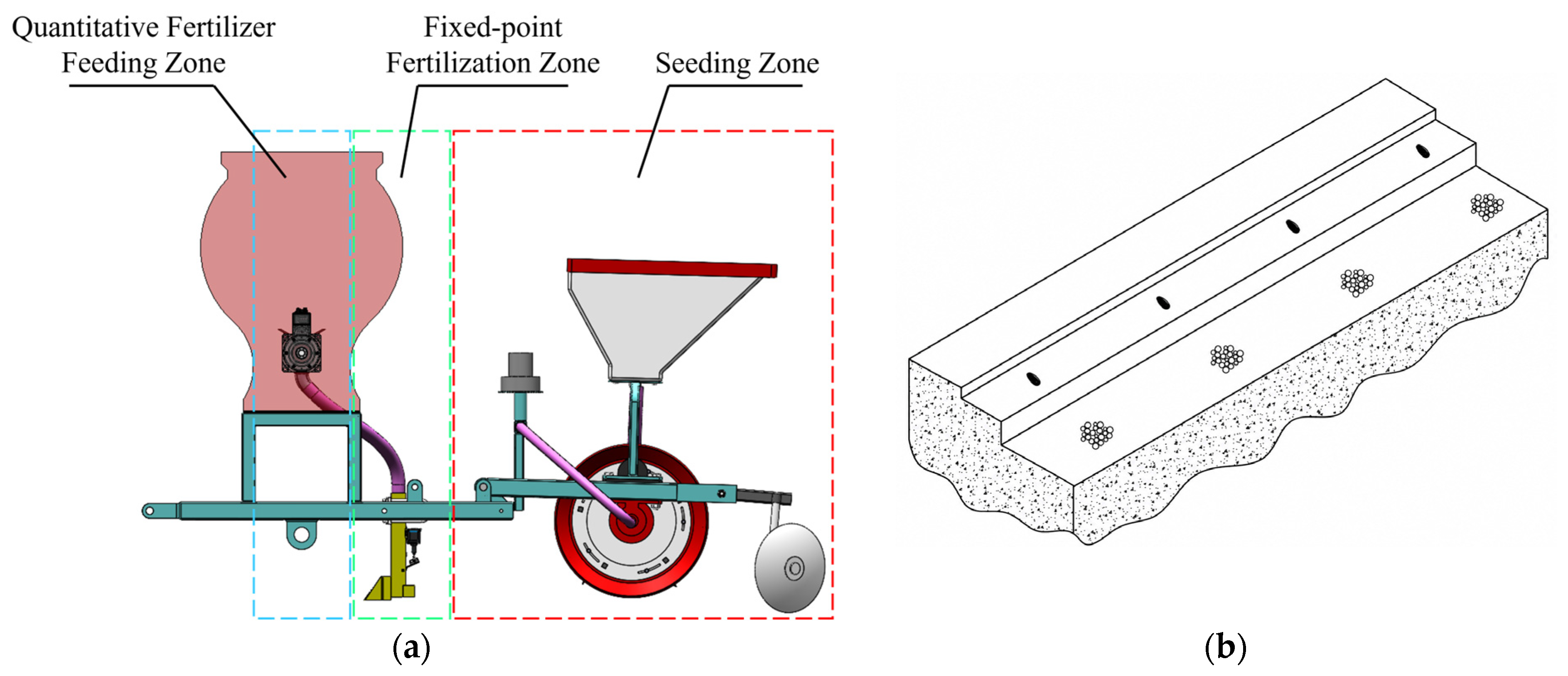
The main operating components are shown in Figure 3. As the sunflower hole fertilization planter advances, the duckbill seed metering device remains in contact with the ground and rotates continuously. Duckbill valves are installed on the seed metering device, including a fixed duckbill valve and a movable duckbill valve. The fixed duckbill valve rotates with the seed metering device and gradually penetrates the soil to form a seed furrow. Subsequently, the fixed duckbill valve leaves the soil, while the movable duckbill valve comes into contact with the soil and is forced to open, allowing the seed to fall into the seed furrow under the action of gravity. When the movable duckbill valve completely leaves the soil, it closes under the action of the spring, thereby completing one sowing operation.
Figure 3.
Working Principle: (a) Main Operating Components of the Sunflower Hole Fertilization Planter; (b) Schematic Diagram of Seed–Fertilizer Positioning.
An electrically driven fertilizer metering device is installed beneath the fertilizer box and is driven by a servo motor. Meanwhile, the motor speed is adjusted in real time according to the operating speed and the target fertilizer application rate. Since the fertilizer discharged from the electrically driven fertilizer metering device is continuous and cannot directly satisfy the requirement of hole-by-hole application, an intermittent fertilization mechanism is arranged beneath it to temporarily store and release the fertilizer. To obtain the operating speed of the planter and ensure that the fertilizer is applied near the seeds, a position-triggering mechanism consisting of a speed measuring disc (composed of a fixed disc and a rotating disc) and a Hall sensor is introduced. The speed measuring disc rotates synchronously with the duckbill seed metering device. When the magnet passes the Hall sensor, high- and low-level signal changes are generated, enabling the control system to identify the sowing position and trigger the baffle action accordingly. The fertilizer temporarily stored in the fertilization chamber falls into the fertilization furrow under the action of gravity, thereby completing one hole fertilization operation. After fertilizer discharge is completed, the baffle returns to its original position and re-enters the fertilizer storage state while waiting for the next trigger signal. Simultaneously, the pulse signal output by the speed measuring disc is used to calculate the real-time operating speed of the planter and serves as the input of the rotational speed model of the electrically driven fertilizer metering device, thereby enabling real-time adjustment of the fertilizer application rate. Considering that a certain installation distance exists between the sowing unit and the fertilization unit, a time delay occurs between fertilizer release from the baffle and fertilizer deposition into the soil. Therefore, angular compensation of the fertilization triggering timing is achieved by adjusting the angular position of the magnet on the speed measuring disc, thereby enabling targeted fertilizer application near the seeds and ensuring consistency between fertilization hole spacing and sowing hole spacing.
2.2. Design of Key Components
At present, the design of sowing devices has become relatively mature both domestically and internationally and can be mainly classified into mechanical and pneumatic types. Mechanical sowing devices are characterized by simple structures and low cost; however, their performance is greatly affected by seed morphology, making them prone to multiple seeding and missed seeding. In contrast, pneumatic sowing devices exhibit good plant spacing uniformity and strong adaptability to variations in seed morphology. Therefore, a duckbill pneumatic seed metering mechanism with a mature and proven structure was selected as the sowing unit in this study [29,30]. On this basis, the fertilization method was taken as the primary focus for improvement.
2.2.1. Electrically Driven Fertilizer Metering Device
Conventional fertilizer metering devices generally employ a mechanical transmission mode consisting of a ground wheel, chain drive, and fertilizer metering shaft. Although this transmission mode is characterized by a simple structure and low cost, ground wheel slippage is likely to occur under uneven field surface conditions, resulting in deviations between the actual fertilizer application rate and the theoretical value [31,32]. To address this problem, the ground wheel transmission scheme was replaced with a motor-driven scheme based on the original fertilizer metering structure. The operating speed of the planter is obtained through a Hall sensor, and the control system adjusts the motor speed in real time according to the operating speed, thereby maintaining synchronization between the fertilizer metering shaft and the operating speed.
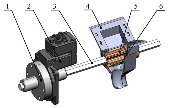
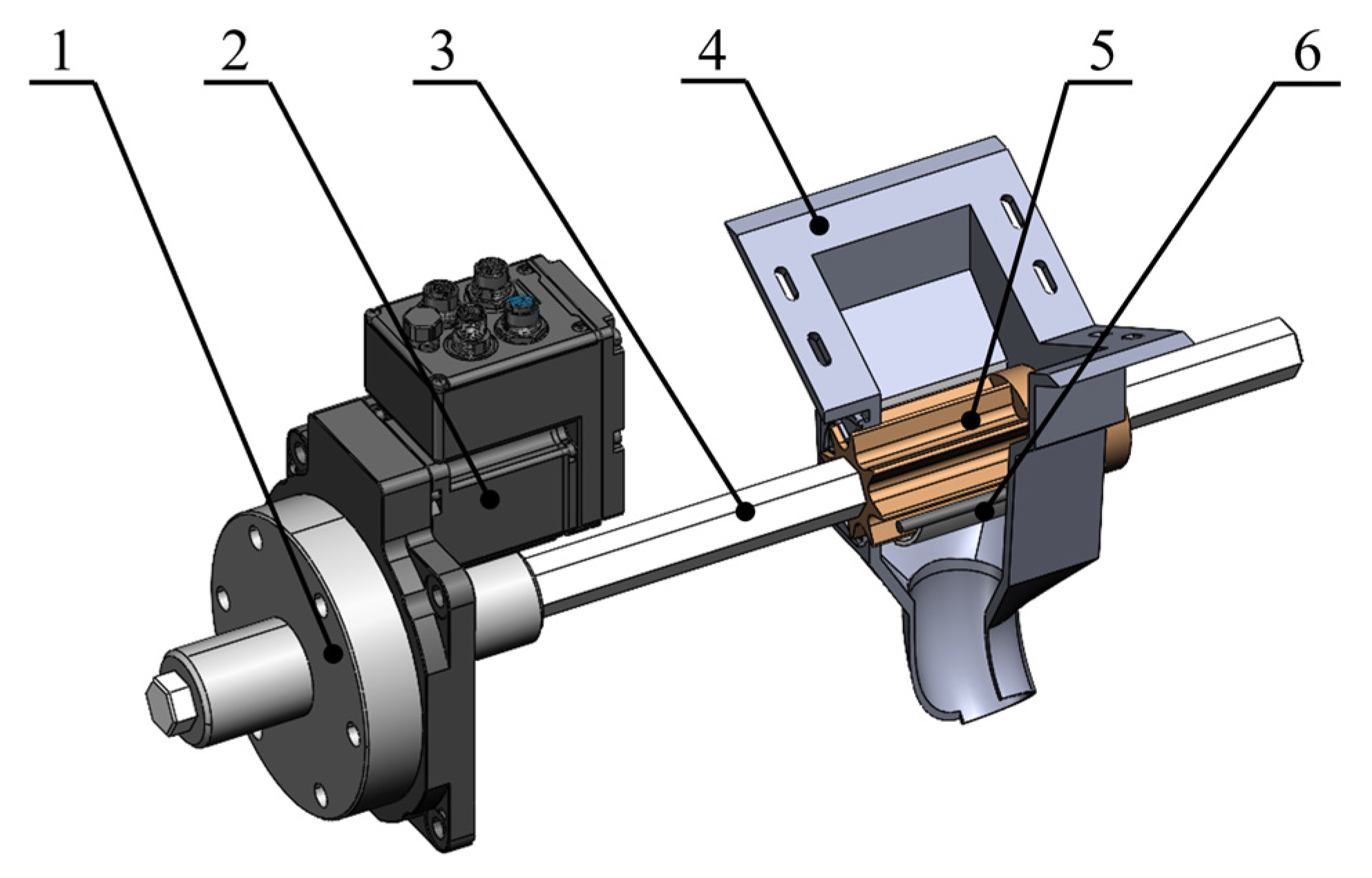
As shown in Figure 4, the electrically driven fertilizer metering device mainly consists of a servo motor, a fertilizer metering shaft, a housing, a fertilizer metering wheel, and a brush. The device is installed at the discharge outlet located at the bottom of the fertilizer box. The fertilizer metering wheel is fixed on the fertilizer metering shaft and is uniformly distributed with six fertilizer metering grooves along its circumference, which are used to continuously and quantitatively discharge fertilizer from the fertilizer box into the intermittent fertilization mechanism. The brush is installed at the outer edge of the fertilizer metering wheel to remove excess fertilizer from the fertilizer metering grooves and to prevent fertilizer leakage caused by the clearance between the housing and the fertilizer metering wheel. A motor is employed as the power source, and the motor is connected to the fertilizer metering shaft through a flange, thereby enabling independent driving of the fertilizer metering device.
Figure 4.
Schematic Diagram of the Electrically Driven Fertilizer Metering Device: 1. Flange; 2. Servo motor; 3. Fertilizer metering shaft; 4. Housing; 5. Fertilizer metering wheel; 6. Brush.
To determine the required rotational speed range of the servo motor, it is necessary to establish the relationship between the target fertilizer application rate per hole and the fertilizer discharge rate of the fertilizer metering device. The target fertilizer application rate per hole is given by
where m is the target fertilizer application rate per hole, g; M is the fertilizer application rate, kg/mu (1 mu ≈ 0.0667 hectare); and DS is the planting density, plants/mu.
According to the agronomic requirements [33], granular compound fertilizer is currently the predominant fertilizer type used in sunflower production in China, with a fertilizer application rate generally ranging from 15 to 20 kg/mu. The adoption of hole fertilization can improve fertilizer utilization efficiency and reduce fertilizer consumption [34,35]. Therefore, the fertilizer application rate was appropriately adjusted, and a range of 10–15 kg/mu was selected for this study. The planting density was set at 2000 plants/mu. Accordingly, by substituting the relevant parameters into Equation (1), the target fertilizer application rate per hole for sunflower was determined to be 5–7.5 g under field operating conditions.
The fertilizer discharge rate of the fertilizer metering device is given by [27]
where Q is the fertilizer discharge rate of the fertilizer metering device, g/s; v is the operating speed, m/s; and l is the plant spacing, taken as 0.4 m.
An operating speed range of 3–7 km/h was selected. By substituting the relevant parameters into the calculation, the required fertilizer discharge rate was determined to be 10.42–36.46 g/s.
To obtain the fertilizer discharge amount per revolution of the fertilizer metering device, a calibration test was conducted. The fertilizer metering device was fixed on a test bench, and the fertilizer to be tested was supplied from above. The fertilizer metering wheel was rotated uniformly for three revolutions, and the mass of the discharged fertilizer was measured using an electronic balance. The test was repeated five times, and the average value was taken as the fertilizer discharge amount per revolution. The fertilizer discharge amount per revolution was determined to be 171.91 g.
Therefore, the relationship between the fertilizer discharge rate Q and the rotational speed of the fertilizer metering shaft is given by
By combining Equations (2) and (3), the required rotational speed of the servo motor can be expressed as
where q is the fertilizer discharge amount per revolution of the fertilizer metering device, g; n is the target rotational speed of the fertilizer metering shaft, r/min (rpm); and i is the motor reduction ratio.
During operation, since the fertilizer application rate is proportional to the motor rotational speed, fluctuations in operating speed will result in non-uniform fertilizer application if the motor rotational speed remains unchanged. Therefore, the motor rotational speed needs to be adjusted in real time according to the operating speed of the planter. As no obvious slippage occurs in the seed metering device under normal operating conditions, its circumferential linear velocity can be approximated as the operating speed of the planter. A speed measuring disc was installed on the seed metering device. According to the diameter of the seed metering device and the sunflower plant spacing requirement, five magnets were uniformly distributed on the speed measuring disc, and a Hall sensor was fixed on the frame with a spacing of 5 mm from the magnets. During operation, as the seed metering device rotates with the forward movement of the planter, the magnets successively pass through the sensing area of the Hall sensor and generate corresponding pulse signals. The controller processes these pulse signals to obtain the operating speed of the planter.
The operating speed is given by
where ω is the angular velocity of the seed metering device, rad/s; R is the radius of the seed metering device, m; rs is the number of revolutions of the seed metering device within one measurement cycle, r; T is the speed measurement period, s; and N is the number of pulses acquired within the speed measurement period.
After obtaining the operating speed of the planter, it is necessary to further convert it into a motor rotational speed model. By substituting the operating speed into the target motor rotational speed calculation model, the following expression can be obtained:
2.2.2. Intermittent Fertilization Mechanism
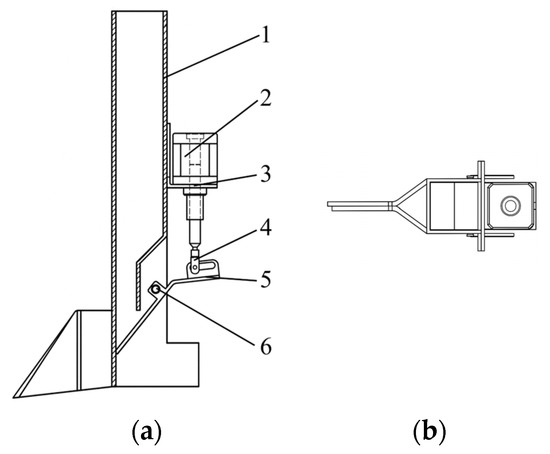
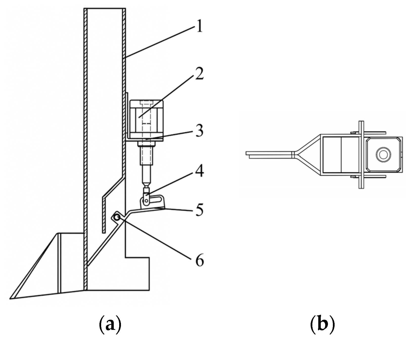
As shown in Figure 5, the intermittent fertilization mechanism mainly consists of a fertilization furrow opener, a baffle, a connecting shaft, a Y-shaped connector, and a linear motor. The fertilization furrow opener serves both furrow-opening and fertilizer-storage functions. The shank section is designed as a square tube, and the upper part of the shank is connected to the fertilizer delivery tube to receive fertilizer discharged from the electrically driven fertilizer metering device. The fertilization furrow opener is fixed to the frame through a U-bolt clamp, allowing the furrow-opening depth to be adjusted within a certain range. The width of the furrow opener was set to 50 mm, and the plate thickness was 2 mm. The baffle is installed at the fertilizer outlet, and intermittent fertilizer application is achieved through the opening and closing actions of the baffle. A linear motor is mounted on the side of the fertilization furrow opener and serves as the power unit. The reciprocating linear motion of the motor drives the baffle to achieve rapid opening and closing. The baffle is connected to the linear motor through a connecting shaft and a Y-shaped connector.
Figure 5.
Schematic Diagram of the Intermittent Fertilization Mechanism: 1. Furrow opener; 2. Linear motor; 3. Motor mounting plate; 4. Y-shaped connector; 5. Baffle; 6. Rotating shaft. (a) Front view; (b) Top view.
The baffle and the linear motor constitute the main components of the intermittent fertilization mechanism and are used to achieve temporary fertilizer storage and intermittent fertilizer application. The opening angle of the baffle has a geometric relationship with the stroke of the linear motor, while the opening duration of the baffle determines whether the fertilizer mass can be completely discharged. Therefore, the motion parameters associated with the opening and closing process need to be determined.
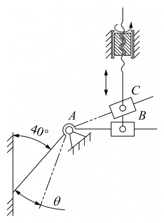
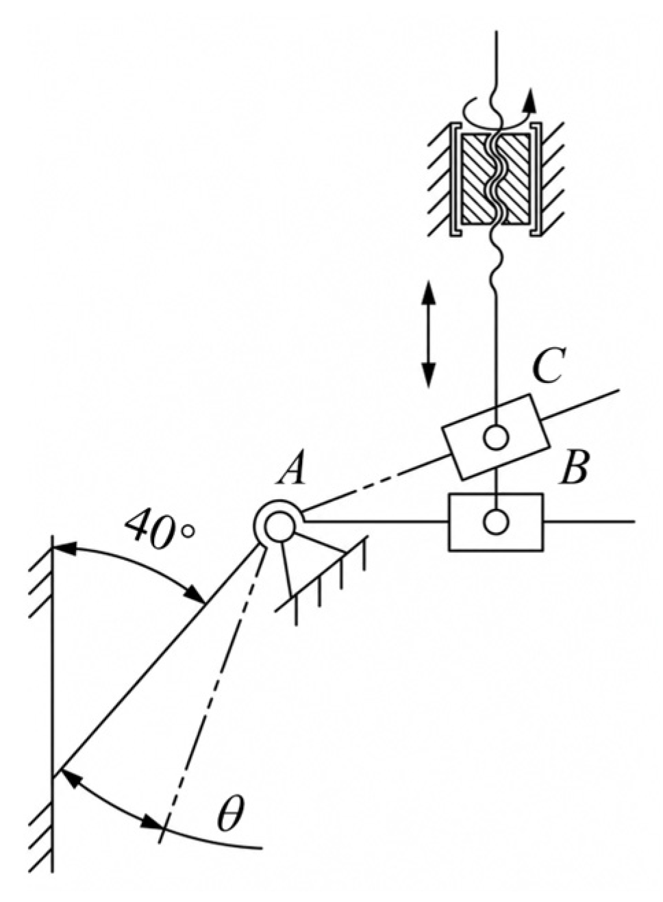
When the baffle is arranged horizontally in the closed position, fertilizer particles tend to accumulate above the baffle and are difficult to form into a concentrated fertilizer mass. To ensure concentrated fertilizer application, the baffle was installed at an inclined angle, allowing the fertilizer mass to accumulate on one side of the fertilizer-converging plate. The kinematic schematic of the mechanism is shown in Figure 6.
Figure 6.
Kinematic Schematic of the Intermittent Fertilization Mechanism: A represents the fixed hinge point, B represents the hinge position when the baffle is closed, and C represents the hinge position when the baffle is open.
When the inclination angle is too small, the height of the fertilizer mass accumulated on one side of the baffle increases. To ensure that the fertilizer mass can completely detach from the baffle and fall freely, a longer fertilizer discharge duration is required. Conversely, when the inclination angle is too large, the rotational displacement of the baffle during opening increases accordingly, resulting in a greater stroke requirement for the linear motor. Consequently, the baffle opening duration is prolonged, thereby reducing the available fertilizer storage time. Considering these factors comprehensively, and with reference to the measured angle of repose of the diammonium phosphate fertilizer (approximately 28–32°), the inclination angle was set to 40°. This value exceeds the repose angle to ensure smooth sliding, while avoiding excessive stroke requirements that would compromise storage time. Given the furrow opener width of 50 mm and plate thickness of 2 mm on each side, the internal channel width available for fertilizer passage was 46 mm. The baffle length was calculated as 71.56 mm (L = 46/sin 40°).
A fixed guide plate was installed above the baffle to direct the fertilizer to fall in a predetermined direction. In addition, a layer of rubber was attached to the inner surface of the baffle to mitigate collisions between the fertilizer particles and the baffle during temporary storage, thereby promoting the rapid accumulation of fertilizer into a concentrated fertilizer mass. The baffle opening angle was determined based on the effective discharge area requirement and the kinematic constraints of the linear motor. If the opening angle of the baffle is too small, the effective flow area of the fertilizer outlet becomes insufficient, preventing most of the fertilizer from sliding out in a timely manner. Therefore, based on preliminary experiments, the baffle opening angle was set to 20°. According to the baffle opening angle and the geometric dimensions of the mechanism, the required stroke of the linear motor can be calculated as
where le is the stroke of the linear motor, mm; lAB is the distance between the baffle rotation center and the center of the Y-shaped connector when the baffle is in the closed position, mm; lAC is the distance between the baffle rotation center and the center of the Y-shaped connector when the baffle is in the open position, mm; and θ is the opening angle of the baffle.
A single fertilization process consists of four stages: baffle opening, fertilizer discharge, baffle closing, and fertilizer storage. Specifically, when a magnet mounted on the speed measuring disc passes the Hall sensor, a pulse signal is generated. Upon receiving this signal, the control system outputs a control command to actuate the linear motor. The push rod of the linear motor extends, driving the baffle to rotate about the shaft and open. After the baffle is opened, the fertilizer temporarily stored during the previous fertilization cycle falls from the fertilizer outlet in the form of a fertilizer mass under the action of gravity. Upon completion of fertilizer discharge, the linear motor drives the baffle back to the closed position. When the baffle is fully closed, fertilizer continuously supplied by the electrically driven fertilizer metering device enters the fertilizer storage chamber and is temporarily stored for the next fertilization cycle. As the duckbill seed metering device continues to rotate, the magnet on the speed measuring disc passes the Hall sensor again, triggering the next baffle-opening action and thereby forming a periodic hole fertilization process.
The time required for a single fertilization cycle is equal to the interval between two adjacent fertilization trigger signals. Since the forward speed of the planter is not constant during field operation, an increase in operating speed results in a higher frequency at which the magnets pass the Hall sensor, thereby shortening the interval between adjacent trigger signals. Therefore, the working time of the mechanism must be verified. Under the maximum operating speed condition, the minimum interval between trigger signals can be obtained as
where tmin is the minimum interval between trigger signals, s; vmax is the maximum operating speed of the planter, taken as 1.94 m/s; and z is the number of magnets mounted on the speed measuring disc.
Since the stroke of the linear motor remains constant during both the opening and closing processes of the baffle, the baffle opening time is equal to the baffle closing time, which can be expressed as
where t1 is the baffle opening time, s; t3 is the baffle closing time, s; s is the travel stroke of the linear motor, m; and vm is the moving speed of the linear motor, m/s.
Neglecting air resistance, the fertilizer discharge time can be expressed as
where t2 is the fertilizer discharge time, s; h is the height at which the fertilizer mass completely separates from the baffle, m; and g is the gravitational acceleration, taken as 9.81 m/s2.
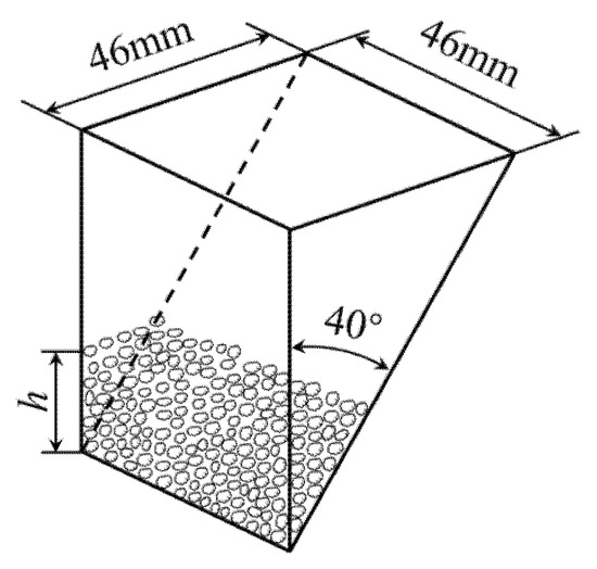
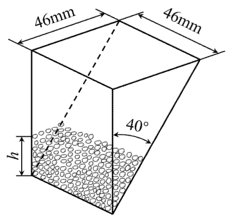
In this study, diammonium phosphate was selected as the test fertilizer. Experimental measurements indicated that the bulk density of the fertilizer was 0.976 g/cm3. Taking a fertilizer application rate of 7.5 g per hole as an example, the corresponding fertilizer volume was calculated to be 7.68 cm3. Based on the geometric dimensions of the mechanism, the height (h) of the 7.5 g fertilizer mass when the baffle was in the closed position was approximately 1.99 cm, as shown in Figure 7. To ensure complete separation of the fertilizer mass from the baffle, h was taken as 0.025 m. Under this condition, the fertilizer discharge time (t2) was calculated to be 0.071 s.
Figure 7.
Schematic Diagram of Fertilizer Pile Height.
Therefore, the fertilizer storage time should satisfy
That is, within the fertilizer storage time available under the maximum operating speed condition, the electrically driven fertilizer metering device must be capable of supplying the target fertilizer application rate required by the mechanism. As can be seen from Equation (11), the fertilizer storage time can be increased by reducing the baffle opening and closing duration. Therefore, provided that stable operation of the mechanism is maintained, the baffle opening and closing times can be shortened by increasing the movement speed of the linear motor.
2.2.3. Simultaneous Seed-Fertilizer Application System
The system is centered on a PLC-based embedded controller (Zhejiang Liangshi Intelligent Technology Co., Ltd., Hangzhou, Zhejiang Province, China. LS30-16MT043; Supply voltage: 24 VDC; maximum current: 400 mA; digital input: 8 channels; relay output: 8 channels; communication interface: RS-485) and mainly comprises two output interfaces for controlling the motor of the electrically driven fertilizer metering device and the linear motor, respectively, and one input interface for acquiring signals from the Hall sensor mounted on the seed metering device. The hardware of the control system mainly consists of a touch screen, controller, motor of the electrically driven fertilizer metering device (Shanghai MOONS’ Electric Co., Ltd., Shanghai, China. Rated rotational speed: 3000 r/min; rated torque: 0.64 N·m), linear motor (Shanghai MOONS’ Electric Co., Ltd., Shanghai, China. Rated current: 0.65 A; rated thrust: 23 N@300 rpm; maximum stroke: 25.4 mm), motor driver (Shanghai MOONS’ Electric Co., Ltd., Shanghai, China. Output current: 0.1–5.0 A/phase (sinusoidal peak); operating voltage: 24–48 VDC; communication interface: RS-485), voltage regulation module, and Hall sensor (Yueqing Chaozhong Electric Co., Ltd., Yueqing, Zhejiang, China. Output mode: NPN normally open (NO); rated operating voltage: DC 5–30 V; response time: less than 2 ms).
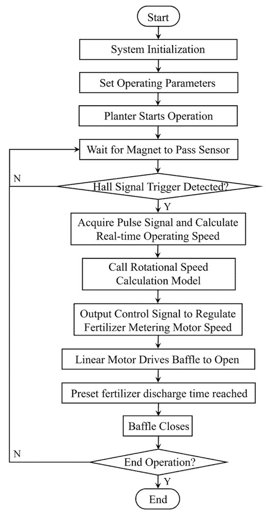
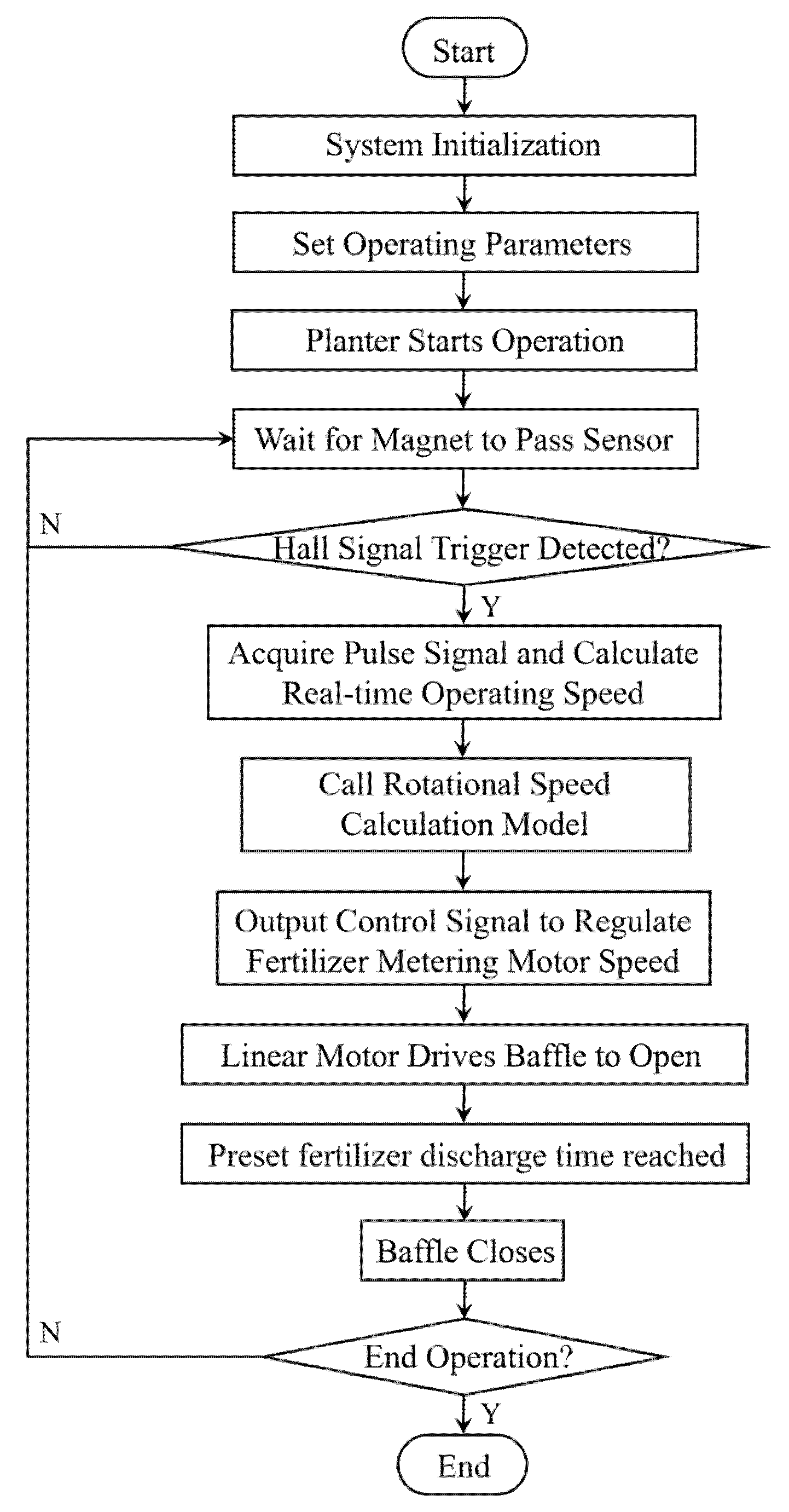
The control software was developed using ladder logic programming in the GX Works2 platform, while the monitoring system software was developed on the VisualCS platform. The primary functions include operating parameter input, operating speed detection, and fertilization control algorithms. The overall control flow of the system is shown in Figure 8. After power-on, the system initializes all the parameters, and operating parameters such as the target fertilizer application rate per hole and plant spacing are entered. Once the parameters are confirmed, the system enters the operating state. When a magnet passes the Hall sensor, a high-to-low or low-to-high level transition signal is generated. According to this signal change, the linear motor drives the baffle to open. After the preset fertilizer discharge time has elapsed, the baffle is closed. Meanwhile, the control system calculates the real-time operating speed based on the pulse signals and uses it as an input to the rotational speed calculation model of the fertilizer metering motor. The target motor rotational speed is then obtained, and a control signal is output to regulate the rotational speed of the fertilizer metering motor.
Figure 8.
Flow Chart of the Control System.
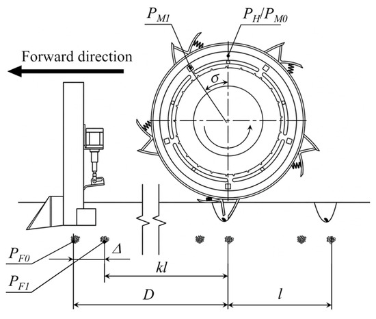
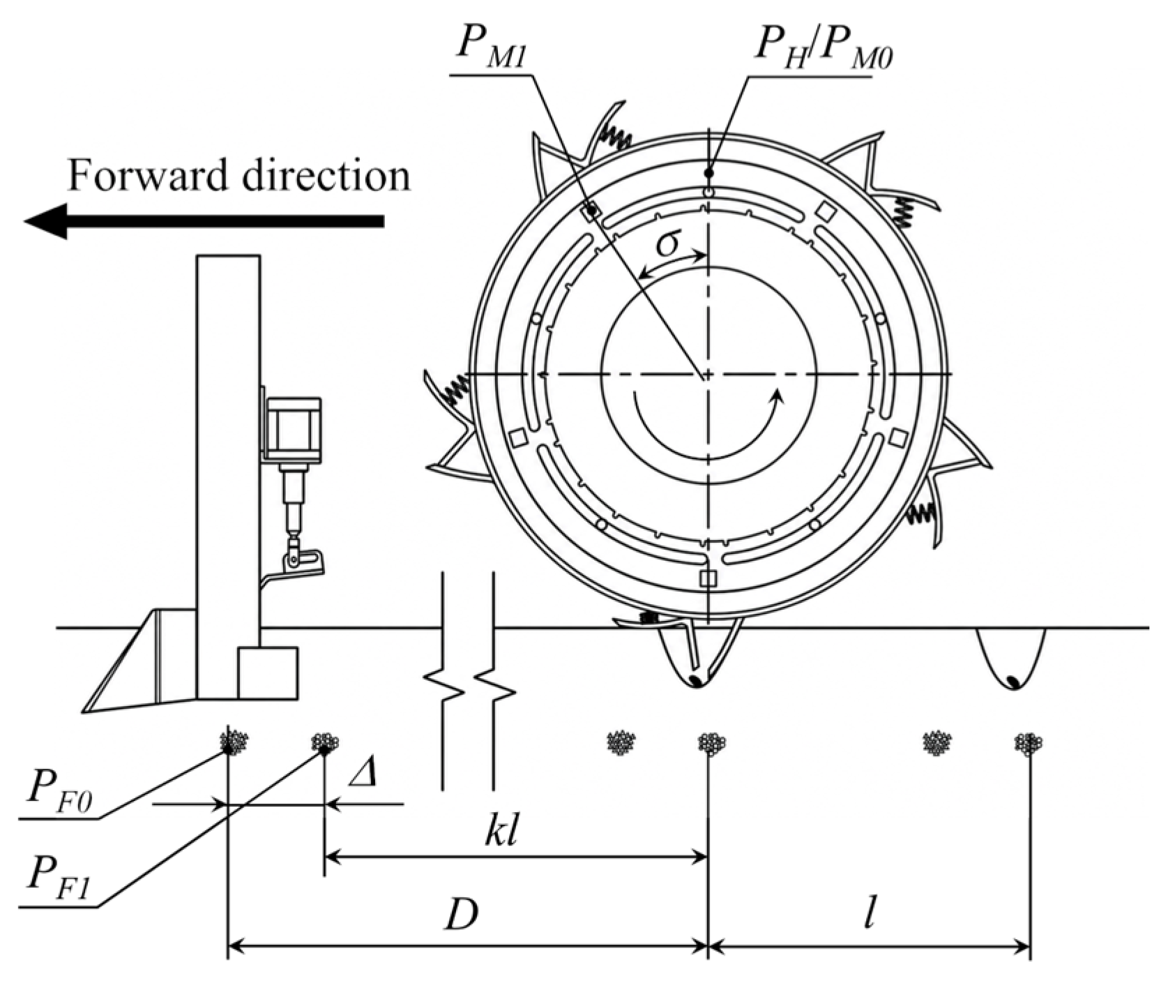
As shown in Figure 9, when the duckbill seed metering device rotates to the seed release position, the duckbill valve opens and completes seed delivery. At this moment, the magnet mounted on the speed measuring disc is located at the initial position PM0, which coincides with the Hall sensor trigger position PH. Upon receiving the trigger signal, the control system actuates the linear motor, causing the baffle to open and discharge fertilizer. Owing to the installation distance between the seeding unit and the fertilization unit on the machine, the fertilizer ultimately falls at position PF0. If no compensation is applied to account for the distance between the two units, a deviation will occur between the fertilizer landing position and the subsequent seed landing position, thereby affecting fertilization performance.
Figure 9.
Schematic Diagram of Position Compensation between Seed and Fertilizer Placement.
To address this issue, a compensation control model for the hole-to-seed fertilization system was established. By adjusting the initial installation position of the magnet on the speed measuring disc, the fertilization trigger timing can be corrected, thereby ensuring that fertilizer is applied in the vicinity of the seed. The compensation distance is primarily determined by the installation distance between the seeding unit and the fertilization unit, together with the target plant spacing, and can be expressed as
where Δ is the compensation distance, cm; D is the installation distance between the seeding unit and the fertilization unit along the forward travel direction, cm; and k is the number of holes contained within the installation distance.
To eliminate the deviation between the fertilizer landing position PF0 and the target fertilization position, and to achieve fertilizer deposition at position PF1, angular compensation of the speed measuring disc is carried out based on the obtained compensation distance. The speed measuring disc adopts a combined structure consisting of a fixed disc and a rotating disc. The fixed disc is mounted on the duckbill seed metering device and rotates synchronously with it, while the rotating disc is connected to the outer side of the fixed disc via bolts, and the magnets are installed on the rotating disc. By adjusting the circumferential installation angle of the magnet, its position is shifted from PM0 to the compensated position PM1, thereby enabling hole fertilization control. In this case, the compensation angle is given by
2.3. Bench Test
2.3.1. Bench Test Conditions
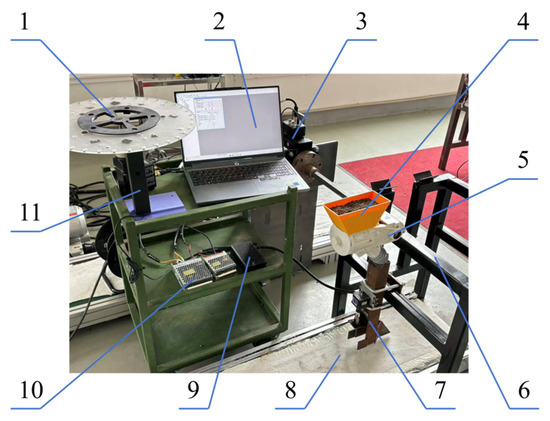
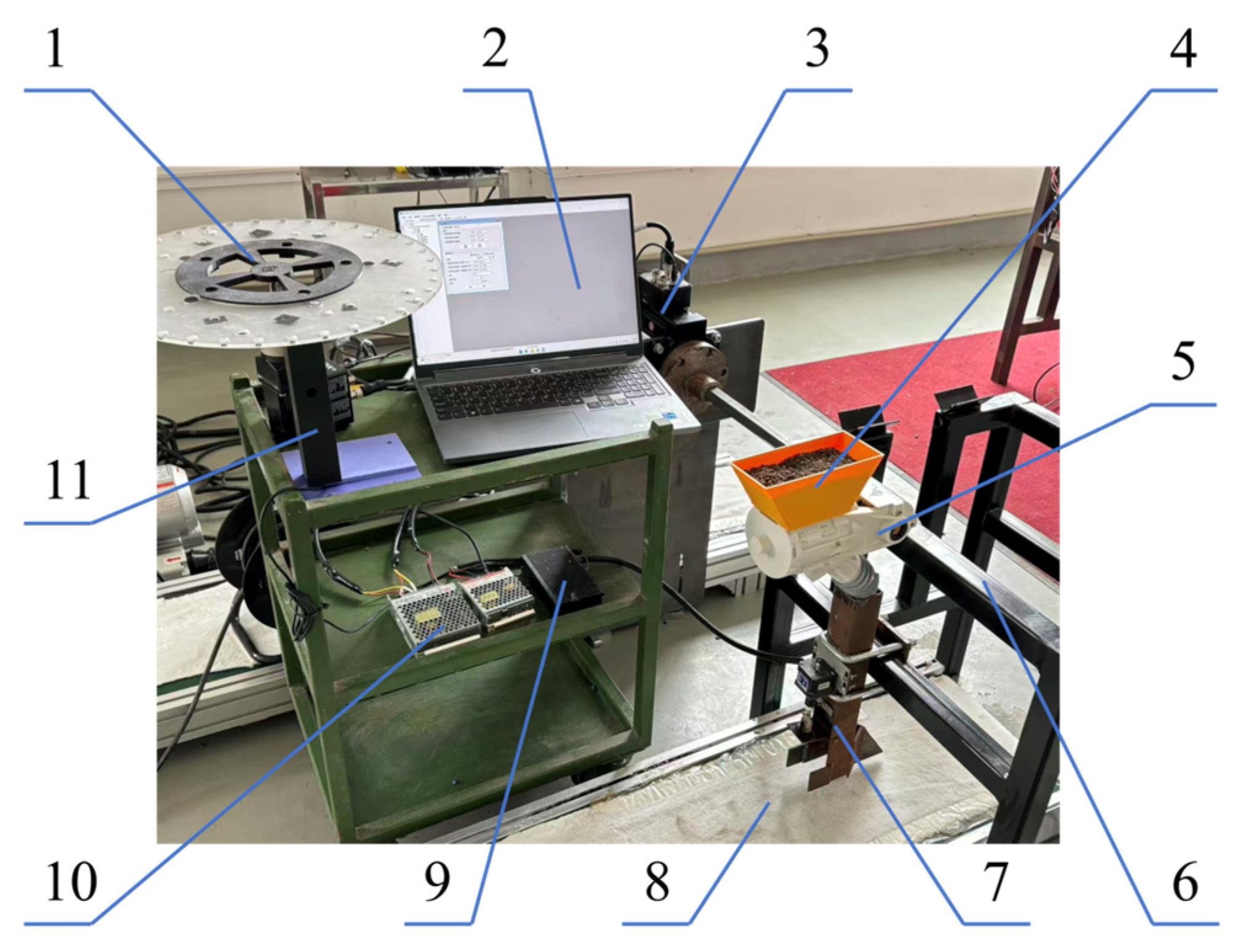
To clarify the influence of key structural parameters of the hole fertilization planter on fertilization quality and to determine the optimal operating parameter combination, a bench test was conducted. The experimental setup is shown in Figure 10. It mainly consists of an outer groove wheel fertilizer metering device, a servo motor, an intermittent fertilization mechanism, a speed measuring disc, a Hall sensor, a conveyor belt, and drivers, among other components.
Figure 10.
Bench Test Platform for Hole Fertilization Performance: 1. Speed measuring disc; 2. Computer; 3. Servo motor; 4. Fertilizer box; 5. Fertilizer metering device; 6. Mounting frame; 7. Intermittent fertilization mechanism; 8. Conveyor belt; 9. Driver; 10. Power supply; 11. Hall sensor.
In order to reduce the rebound effect of fertilizer particles after landing on the conveyor belt surface, a layer of cotton cloth was laid on the belt surface. Considering that the actual seeding unit is relatively large and not suitable for direct installation on the bench test platform, a speed measuring disc driven by a motor was used to replace the seeding mechanism in order to simulate different operating speeds. Diammonium phosphate (Yuntianhua Group, Kunming, China, N:P2O5 = 18:46) was selected as the test fertilizer, and the fertilizer particles were essentially spherical in shape.
2.3.2. Experimental Design and Evaluation Indices
Combining the electrically driven fertilizer metering device, the intermittent fertilization mechanism, and the hole-to-seed fertilization system described above, the target fertilizer application rate per hole (5–7.5 g), the baffle opening time (60–100 ms) [27], and the operating speed (3–7 km/h) [26,27] were selected as experimental factors. The hole spacing error (Y1) and the coefficient of variation in hole fertilizer application rate (Y2) were used as evaluation indices. The coded levels of the factors are listed in Table 2.
Table 2.
Experimental Factors and Levels.
The measurement method of the hole spacing error (Y1) is as follows: after the hole fertilization system operates in a stable state, the most densely accumulated point of fertilizer is taken as the center point. The center-to-center distance between two adjacent fertilization points within the test area is measured. Taking the target hole spacing as the reference, the hole spacing error can be expressed as
where Y1 is the hole spacing error, %; xi is the hole spacing between the i-th sampling point and the adjacent fertilizer point, mm; x0 is the target hole spacing, taken as 40 cm.
The measurement method of the coefficient of variation in the hole fertilizer application rate (Y2) is as follows: fertilizer samples from ten consecutive fertilization holes were collected, and the actual fertilizer application rate per hole was measured using an electronic balance. The coefficient of variation in the hole fertilizer application rate was then calculated based on the target fertilizer application rate per hole, and the calculation formula is given as
where Y2 is the coefficient of variation in the hole fertilizer application rate; mi is the actual fertilizer application rate at the i-th sampling point, g; and is the mean fertilizer application amount for each test group, g.
3. Experimental Results and Analysis
Design-Expert 13 software was used to conduct the Box–Behnken experimental design. A three-factor, three-level design scheme was adopted, and a total of 17 experimental runs were arranged, including five replicated center-point runs. The experimental scheme and corresponding results are shown in Table 3. Each experimental run was repeated three times, and the average value was taken as the final result.
Table 3.
Experimental Scheme and Results.
3.1. Regression Model and Variance Analysis
Regression analysis was conducted on the Box–Behnken experimental results, and a quadratic regression model describing the relationship between the experimental factors and evaluation indices was established as follows:
Y1 = 2.79 − 0.5187A − 0.2412B + 1.42C + 0.395AB − 0.3025AC + 0.2725BC + A2 + 0.53B2 − 0.0775C2
Y2 = 13.36 − 5.01A − 0.5463B − 6.63C + 1.19AB − 0.64AC + 0.115BC + 4.65A2 − 0.8873B2 + 2.44C2
The analysis of the variance results is shown in Table 4. It can be observed that the p-values of the models are all less than 0.0001, indicating that the established quadratic regression models can adequately describe the relationship between the experimental factors and the evaluation indices. Meanwhile, the p-values of the lack-of-fit terms are all greater than 0.05, indicating that the regression equations exhibit a good fitting performance.
Table 4.
Analysis of Variance Results.
3.2. Analysis of Interaction Effects of Factors
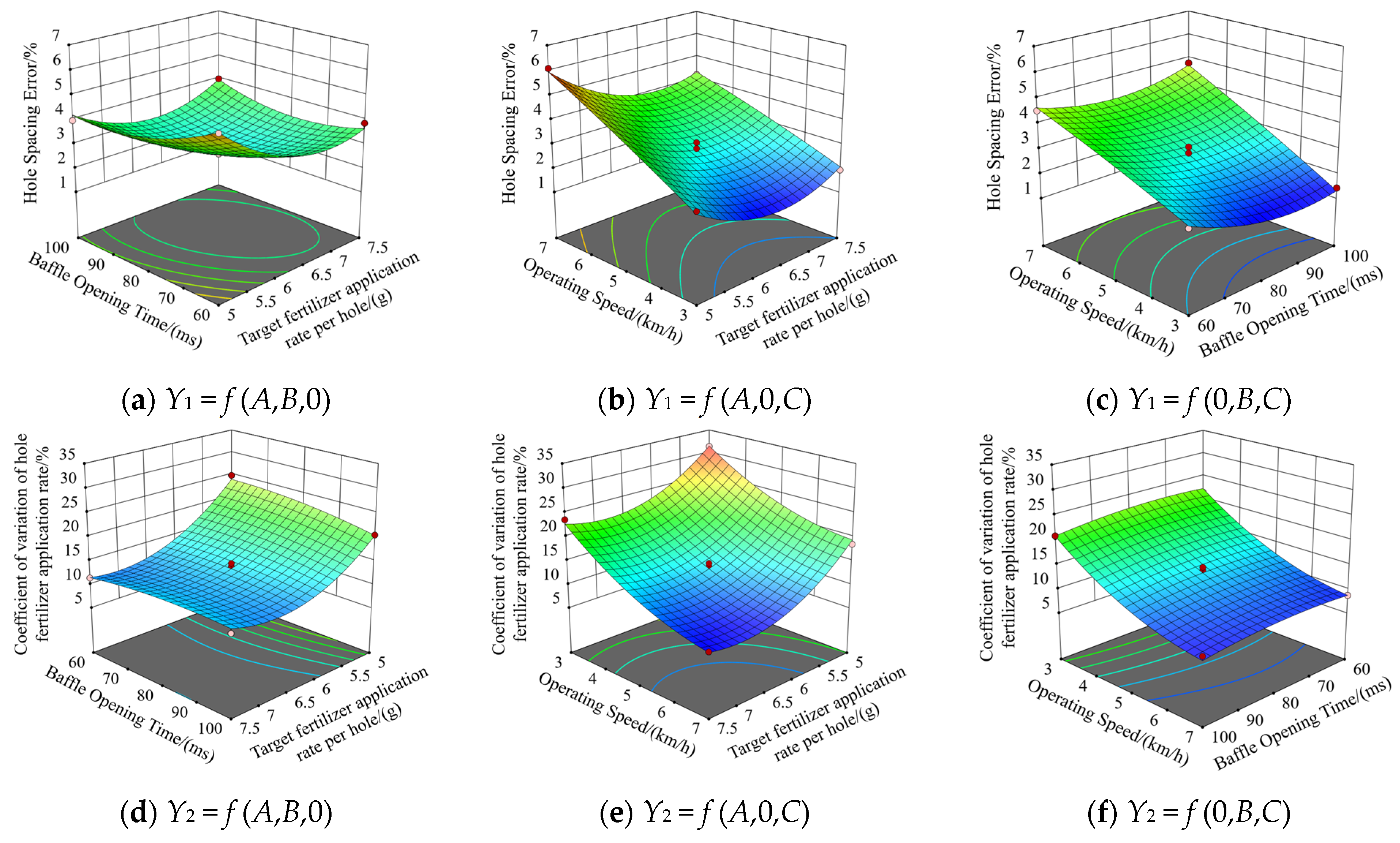
To characterize the influence patterns of each experimental factor on the evaluation indices, response surface plots of the hole spacing error and the coefficient of variation in the hole fertilizer application rate under two-factor interactions were generated based on the quadratic regression model, as shown in Figure 11.
Figure 11.
Effects of Experimental Factors on Evaluation Indices.
From the response surface analysis of the hole spacing error, it can be observed that under the interaction between the single-hole target fertilizer application rate and the baffle opening time, the response surface exhibits a concave shape opening upwards. The hole spacing error first decreases and then increases with increasing single-hole target fertilizer application rate and baffle opening time, reaching a minimum in the central region of the experimental parameter range. Under the interaction between the single-hole target fertilizer application rate and the operating speed, the hole spacing error shows a trend of first decreasing and then increasing with increasing target fertilizer application rate, while it increases gradually with increasing operating speed. Moreover, the higher the operating speed, the greater its influence on the hole spacing error. Under the interaction between baffle opening time and operating speed, a similar pattern is observed, where the hole spacing error first decreases and then increases with increasing baffle opening time, and increases progressively with increasing operating speed.
From the response surface analysis of the coefficient of variation in the hole fertilizer application rate, under the interaction between the single-hole target fertilizer application rate and the baffle opening time, the coefficient of variation decreases gradually with increasing target fertilizer application rate, while exhibiting a slow trend of first increasing and then decreasing with increasing baffle opening time. The contour lines are approximately parallel, indicating that the interaction between baffle opening time and single-hole target fertilizer application rate is weak, and that the influence of baffle opening time on the coefficient of variation is limited. Under the interaction between the single-hole target fertilizer application rate and operating speed, the coefficient of variation decreases with increasing target fertilizer application rate and operating speed. Under the interaction between baffle opening time and operating speed, the coefficient of variation first increases and then decreases with increasing baffle opening time, while decreasing with increasing operating speed.
3.3. Optimization of Operating Parameters
To obtain the optimal operating parameter combination of the planter, the Numerical module of Design-Expert 13 software was used. A multi-objective optimization was performed with the minimization of hole spacing error and the coefficient of variation in hole fertilizer application rate as the optimization objectives, while the single-hole target fertilizer application rate, baffle opening time, and operating speed were taken as design variables. According to the regression analysis results, the constraint equations were established as follows:
Based on the optimization results obtained from the response surface model, the optimal parameters were determined as follows: the single-hole target fertilizer application rate was 6.62 g, the baffle opening time was 86.72 ms, and the operating speed was 4.38 km/h. Under these conditions, the predicted hole spacing error was 2.29%, and the coefficient of variation in the hole fertilizer application rate was 14.46%.
3.4. Field Experiment
3.4.1. Experimental Conditions
To further verify the performance of the hole fertilization planter under the optimal parameter conditions, a field experiment was conducted in May 2026 in Zhangxuan Village, Longqiu Town, Gaoyou City, Jiangsu Province. After land preparation, the soil surface was relatively level, meeting the requirements for sunflower seeding and fertilization operations.
The experimental crop was edible sunflower, and the seed variety used in the experiment was FY928 dwarf sunflower. The fertilizer used in the experiment was diammonium phosphate, which was consistent with that used in the previous experiments.
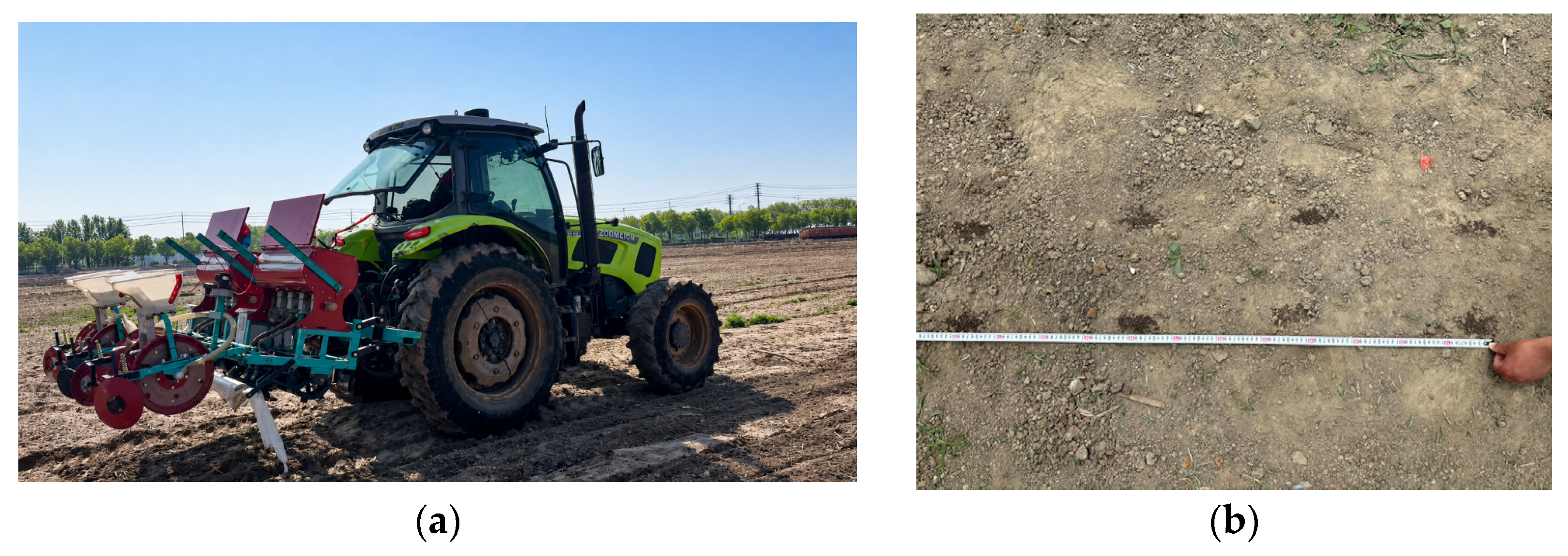
The experimental equipment and instruments mainly included the self-developed hole fertilization planter, a tractor, a measuring tape, a steel ruler, a small shovel, an electronic balance, and a sieve. The field experiment is shown in Figure 12.
Figure 12.
Field Experiment: (a) Performance test of the planter; (b) Hole fertilization operation effect.
Before the experiment, the operating parameters were set according to the optimal parameter combination obtained from Design-Expert 13. The single-hole target fertilizer application rate was set to 6.6 g, the baffle opening time was set to 87 ms, and the operating speed was set to 4.4 km/h.
3.4.2. Results Analysis
The optimal parameter combination obtained from Design-Expert 13 was applied to the hole fertilization system for validation experiments. Under the optimized conditions, three repeated experiments were conducted, and the average values of each evaluation index were taken as the final results.
The hole spacing error was determined based on the relative positions of adjacent fertilizer application points. The distance between adjacent fertilizer application centers along the forward direction of the planter was measured using a measuring tape. In each repetition, ten consecutive fertilizer application points were randomly selected from the stable operating section for measurement, and the average hole spacing error was calculated.
The coefficient of variation in hole fertilizer application rate was determined by collecting fertilizer samples from individual application points. In each repetition, ten consecutive fertilizer application points were selected, and the fertilizer at each point was manually collected. After removing impurities using a sieve, the fertilizer mass in each hole was measured using an electronic balance. The coefficient of variation in hole fertilizer application rate was calculated based on the measured fertilizer mass.
The experimental results showed that under the optimized parameter conditions, the hole spacing error was 1.78%, with the hole spacing of 39.9 ± 0.84 cm, and the coefficient of variation in hole fertilizer application rate was 15.87%, with the fertilizer application rate per hole of 6.67 ± 1.06 g. Compared with the predicted values of the model, the relative errors between the measured and predicted results of the evaluation indexes used in the response surface optimization were both less than 5%, indicating good consistency between the regression model predictions and the experimental results. Therefore, the established response surface model can effectively reflect the influence of the experimental factors on the performance of the hole fertilization system.
Based on the conventional planting density of 2000 plants per mu and a fertilization rate of 6.6 g per hill, the precise fertilization strategy requires a total application of 13.2 kg per mu. In comparison, conventional fertilization typically ranges from 15 to 20 kg per mu. This indicates that precision fertilization can effectively reduce fertilizer input by 12–34%, while maintaining crop yield performance.
4. Discussion
Hole fertilization technologies have primarily been investigated for crops such as maize and wheat, whereas relatively limited studies have focused on sunflower production. Owing to differences in planting patterns, crop growth characteristics, and seed–fertilizer placement requirements, fertilization systems developed for other crops may not fully satisfy the operational requirements of sunflower cultivation. Therefore, the development of a dedicated hole fertilization system for sunflower cultivation is of practical significance for improving fertilizer placement accuracy and reducing unnecessary fertilizer input.
The developed system integrates an electrically driven fertilizer metering device with an intermittent fertilization mechanism to achieve seed–fertilizer synchronized placement. The electrically driven metering device enables independent control of fertilizer delivery, reducing the influence of mechanical transmission deviations on application uniformity. Meanwhile, the intermittent fertilization mechanism is triggered by pulse signals generated when magnets on the speed-measuring disc pass through the Hall sensor, enabling fertilizer discharge precisely at positions corresponding to seed placement. This configuration is expected to provide a flexible and responsive platform for sunflower hole fertilization.
Compared with representative hole-fertilization mechanisms, Wu et al. [26] and Li et al. [27] developed intermittent hole-fertilization systems with coefficients of variation in hole fertilizer application rate of 9.70% and 8.00%, and hole spacing errors of 8.23% and 3.90%, respectively. However, the former relies on a linkage-driven duckbill valve with a relatively complex linkage structure, whereas the latter requires additional pneumatic and pressure-control components. The grooved-wheel device developed by Liao et al. [15] and the cavity-disc device developed by Du et al. [22] achieved coefficients of variation in hole fertilizer application rate of 16.07% and 9.36%, and hole spacing errors of 7.58% and 3.00%, respectively. The developed planter achieved a coefficient of variation in hole fertilizer application rate of 15.87% and a hole spacing error of 1.78%, with the fertilizer application rate per hole of 6.67 ± 1.06 g. From an economic perspective, the proposed system has the potential to reduce fertilizer input by approximately 12–34% compared with conventional fertilization practices, thereby reducing fertilizer costs.
Nevertheless, several limitations remain in the current system. First, the coefficient of variation (CV) of hole fertilizer application rate obtained in this study (15.87%) is higher than several previously reported values. This is likely attributable to the larger plant spacing adopted in this study (40 cm vs. 20–30 cm in the cited studies) and the inherent circumferential non-uniformity of the fluted-wheel metering device. Specifically, the larger spacing requires more rotations of the metering shaft per fertilization event, allowing the slight discharge deviations associated with each rotation to accumulate progressively within each hole, thereby increasing hole-to-hole variability. Given that no standardized CV criteria or quantitative CV–yield relationships are currently available for sunflower hole fertilization, we regard this value as preliminarily acceptable. Second, the fertilizer metering device adopts an external fluted-wheel structure, and periodic abnormal fertilizer discharge was occasionally observed during experiments, indicating that further optimization of the metering structure is required. Third, the field experiment was mainly conducted under the optimized operating speed, and the adaptability of the control system under variable-speed conditions requires further investigation. Fourth, the structural parameters of the intermittent fertilization mechanism were determined based on agronomic requirements, theoretical analysis, and preliminary tests, and their effects on fertilizer discharge stability, accumulation morphology, and dropping position require further clarification. Future studies will focus on optimizing the fertilizer metering mechanism and evaluating the system performance under different fertilizer characteristics and operating conditions. In addition, direct measurements such as the horizontal seed–fertilizer distance and broader economic and environmental indicators may be considered in future multidisciplinary evaluations.
5. Conclusions
- (1)
- To address the low fertilizer utilization efficiency associated with strip fertilization in sunflower cultivation, a hole fertilization planter for sunflower was designed.
- (2)
- A motor-driven fertilizer metering system was developed to replace the traditional ground-wheel-driven fertilizer shaft. Based on the established relationship among target fertilizer application rate, fertilization operating speed, and fertilizer shaft rotational speed, the target fertilizer rate and operating speed were converted into the target motor speed, enabling active speed-following control of the fertilizer shaft.
- (3)
- An intermittent fertilization mechanism was designed. Key structural parameters were determined according to agronomic requirements. The minimum triggering interval time and the linear motor performance parameters were established. Intermittent hole fertilization was achieved through the coordinated operation of the linear motor and baffle mechanism.
- (4)
- A PLC-based hole fertilization control system was developed. Pulse signals generated by the combination of magnets and Hall sensors on the seeding wheel were used as triggers for fertilization actions. Geometric compensation for the installation distance between seeding and fertilization units was introduced to ensure alignment between fertilization and seeding positions.
- (5)
- Based on a Box–Behnken experimental design, regression models between process parameters and performance indices (hole spacing error and coefficient of variation in hole fertilizer application rate) were established. The optimal parameter combination was obtained as follows: target fertilizer application rate of 6.6 g, baffle opening time of 87 ms, and operating speed of 4.4 km/h. Under these conditions, the developed planter achieved a hole spacing error of 1.78% (superior to the 3.00–8.23% reported in cited studies) and a coefficient of variation in hole fertilizer application rate of 15.87% (comparable to the 8.00–16.07% reported in cited studies).
- (6)
- Several limitations of the current system warrant further investigation, including the occasionally observed abnormal fertilizer discharge, the limited validation under variable operating speeds, and the unclear effects of structural parameters on discharge stability and placement accuracy. Future efforts will concentrate on optimizing the metering mechanism and evaluating system performance across a broader range of fertilizer types and field conditions.
Author Contributions
Conceptualization, H.F., T.S. and Q.Z.; methodology, H.F. and J.L.; software, J.L. and R.Z.; validation, J.W., R.Z. and Q.Z.; formal analysis, H.F. and Q.Z.; investigation, J.L. and H.F.; resources, H.F. and T.S.; data curation, J.L. and J.W.; writing—original draft preparation, H.F. and J.L.; writing—review and editing, H.F. and Q.Z.; visualization, Q.Z.; supervision, Q.Z.; project administration, H.F.; funding acquisition, Q.Z. All authors have read and agreed to the published version of the manuscript.
Funding
This study was supported by the China Postdoctoral Science Foundation, grant number 2025M772490.
Institutional Review Board Statement
Not applicable.
Data Availability Statement
The original contributions presented in this study are included in the article. Further inquiries can be directed to the corresponding author.
Conflicts of Interest
Author Tao Sheng was employed by the company Yangzhou Dongbo Electronic Technology Co., Ltd. The remaining authors declare that the research was conducted in the absence of any commercial or financial relationships that could be construed as a potential conflict of interest.
References
- Zhang, X.J.; Ma, S.T.; Zhu, X.L.; Yuan, P.; Yu, M.; Liu, Y. Design and experiment of a variable-gap eccentric multi-link threshing device for oil sunflower. Trans. Chin. Soc. Agric. Eng. 2020, 36, 26–33. [Google Scholar]
- Zhu, X.; Xu, Y.; Han, C.; You, J.; Zhang, X.; Mao, H.; Ma, X. Design and experiment of in-situ bionic harvesting device for edible sunflower. Agriculture 2024, 14, 1169. [Google Scholar] [CrossRef] [Scilit]
- Zhu, X.; Xu, Y.; Han, C.; Yang, B.; Luo, Y.; Qiu, S.; Huang, X.; Mao, H. Parameter calibration and experimental verification of the discrete element model of the edible sunflower seed. Agriculture 2025, 15, 292. [Google Scholar] [CrossRef] [Scilit]
- Dabbour, M.; Jiang, H.; Mintah, B.K.; Wahia, H.; He, R. Ultrasonic-assisted protein extraction from sunflower meal: Kinetic modeling, functional, and structural traits. Innov. Food Sci. Emerg. Technol. 2021, 74, 102824. [Google Scholar] [CrossRef] [Scilit]
- Dabbour, M.; He, R.; Mintah, B.; Tang, Y.; Ma, H. Ultrasound assisted enzymolysis of sunflower meal protein: Kinetics and thermodynamics modeling. J. Food Process Eng. 2018, 41, e12865. [Google Scholar] [CrossRef] [Scilit]
- Li, R.; Wang, S.; Liu, J.; Li, E.; Miao, J.; Wen, X.; Yang, J.; Xu, L.; Li, B.; Jin, C.; et al. Strip application of organic fertilizer in the root zone increases the substitution ratio of chemical nitrogen and sunflower yield in saline-alkali soil. Pedosphere 2025, in press. [Google Scholar] [CrossRef] [Scilit]
- Rasool, G.; Guo, X.; Wang, Z.; Ali, M.U.; Chen, S.; Zhang, S.; Wu, Q.; Ullah, M.S. Coupling fertigation and buried straw layer improves fertilizer use efficiency, fruit yield, and quality of greenhouse tomato. Agric. Water Manag. 2020, 239, 106239. [Google Scholar] [CrossRef] [Scilit]
- Wang, L.; Gao, J.; Qureshi, W.A. Evolution and application of precision fertilizer: A review. Agronomy 2025, 15, 1939. [Google Scholar] [CrossRef] [Scilit]
- Luo, X.; Liao, J.; Zang, Y.; Zhou, Z. Improving agricultural mechanization level to promote sustainable agricultural development. Trans. Chin. Soc. Agric. Eng. 2016, 32, 1–11. [Google Scholar]
- Zhu, Q.; Zhu, Z.; Zhang, H.; Gao, Y.; Chen, L. Design of an electronically controlled fertilization system for an air-assisted side-deep fertilization machine. Agriculture 2023, 13, 2210. [Google Scholar] [CrossRef] [Scilit]
- Deng, Y.; Chen, H.; Chen, M. Does Rural E-Commerce Development in China Facilitate Rural Households’ Green Production Practices, Taking Chemical Fertilizer Reduction as an Example. Agriculture 2026, 16, 162. [Google Scholar] [CrossRef] [Scilit]
- Zhang, Q. Hole fertilization in the root zone facilitates maize yield and nitrogen utilization by mitigating potential N loss and improving mineral N accumulation. J. Integr. Agric. 2023, 22, 1184–1198. [Google Scholar] [CrossRef] [Scilit]
- Guo, Y.; Li, X.; Ding, Z.; Zhang, J.; Wang, M. Effects of different nitrogen application methods on nitrogen use efficiency of sunflower. J. Irrig. Drain. 2018, 37, 20–27. [Google Scholar] [CrossRef]
- Chen, H.; Liu, W.; Gao, L.; Liao, Y.; Li, Q.; Liao, Q. An adaptive spacing of root-zone hole fertilization to improve production and fertilizer utilization of rapeseed. J. Sci. Food Agric. 2024, 104, 6276–6288. [Google Scholar] [CrossRef] [Scilit] [PubMed]
- Liao, Q.; Chen, Y.; Zhang, Q.; Wang, L.; Lin, J.; Du, W. Design and experiment of a side-deep hole fertilization device for rapeseed. Trans. Chin. Soc. Agric. Mach. 2023, 54, 41–52. [Google Scholar]
- Shi, Y.; Chen, M.; Wang, X.; Odhiambo, M.O.; Zhang, Y.; Ding, W. Performance analysis and experiment of a variable-rate fertilizer metering device for rice and wheat precision fertilization. Trans. Chin. Soc. Agric. Mach. 2017, 48, 97–103. [Google Scholar]
- Qi, Z.; Liu, C.; Wang, Y.; Zhang, Z.; Sun, X. Design and Experimentation of Targeted Deep Fertilization Device for Corn Cultivation. Agriculture 2024, 14, 1645. [Google Scholar] [CrossRef] [Scilit]
- Pan, F.; Chen, J.; Wang, B.; Fang, Z.; Liang, J.; He, K.; Ji, C. Design and Field Experiment of Synchronous Hole Fertilization Device for Maize Sowing. Agriculture 2025, 15, 1400. [Google Scholar] [CrossRef] [Scilit]
- Xie, F.P.; Song, X.; Liu, D.W.; Zheng, P.; Liu, M.Z.; Wang, X.S. Design and experiment of an eccentric shaftless spiral precision hole fertilization device for rice. J. Shenyang Agric. Univ. 2025, 56, 121–134. [Google Scholar]
- Liu, Z.D.; Wang, Q.J.; Li, H.W.; He, J.; Lu, C.Y.; Yu, C.C. Analysis and experiment of fertilizer delivery path of pneumatic seed-fertilizer hole-applied device based on CFD-DEM coupling. Trans. Chin. Soc. Agric. Eng. 2019, 35, 18–25. [Google Scholar]
- Liu, Z.D.; Wang, Q.J.; Liu, C.G.; Li, H.W.; He, J.; Liu, J.X. Design and experiment of cavity-disc precision hole fertilization device. Trans. Chin. Soc. Agric. Mach. 2018, 49, 137–144, 355. [Google Scholar]
- Du, X.; Liu, C.L.; Jiang, M.; Yuan, H.; Dai, L.; Li, F.L. Design and experiment of an inclined trapezoidal hole-type fertilizer metering device. Trans. Chin. Soc. Agric. Mach. 2021, 52, 43–53. [Google Scholar]
- Shan, X.; Li, L.; Yan, B.; Dong, J.; Wei, X.; Meng, Z.; Wu, G. Design and test of a rotary centrifugal granular fertilizer hole-applied discharge device. Biosyst. Eng. 2025, 255, 104163. [Google Scholar] [CrossRef] [Scilit]
- Shan, X.; Yan, B.; Yin, Y.; Li, L.; Zhu, Q.; Zhang, A.; Zhao, C.; Meng, Z.; Wu, G. Discharge performance study and vane structure optimization of a rotary centrifugal fertilizer hole-applied discharge device. Biosyst. Eng. 2025, 260, 104318. [Google Scholar] [CrossRef] [Scilit]
- Du, X.; Wang, T.; Chen, S.; Sun, Q.; Xu, Z.; Liu, C. Design and test of high-speed fertilizer point-applied device. INMATEH Agric. Eng. 2023, 71, 834–842. [Google Scholar] [CrossRef] [Scilit]
- Wu, N.; Lin, J.; Li, B.F. Design and experiment of precision hole fertilization system for no-till planter. Trans. Chin. Soc. Agric. Mach. 2018, 49, 64–72. [Google Scholar]
- Li, G.; Su, X.; Zhou, X.; Zhang, X.; Wang, Q.; Wang, C. Design and experiment of a pneumatic-assisted seed-fertilizer hole fertilization device. Trans. Chin. Soc. Agric. Mach. 2024, 55, 191–200. [Google Scholar]
- DB15/T 3577-2024; Technical Code of Water and Fertilizer Integrated by Water Saving and Weight Loss of Sunflower in Saline-Alkali Land of Yellow River Irrigation Area. Inner Mongolia Administration for Market Regulation: Hohhot, China, 2024.
- Chen, Y.; Cheng, Y.; Chen, J.; Zheng, Z.; Hu, C.; Cao, J. Design and experiment of the buckwheat hill-drop planter hole forming device. Agriculture 2021, 11, 1085. [Google Scholar] [CrossRef] [Scilit]
- Zhang, H.; Pan, F.; Han, D.; Liu, J.; Ji, C. Design and Test of a Crawler-Type On-Film Precision Cotton Seeding Device on DEM-CFD. Agriculture 2024, 14, 962. [Google Scholar] [CrossRef] [Scilit]
- Ding, Y.Q.; Yang, L.; Zhang, D.X.; Cui, T.; He, X.T.; Zhong, X.J. GPS-based speed measurement control system for electric-driven corn precision planter. Trans. Chin. Soc. Agric. Mach. 2018, 49, 42–49. [Google Scholar]
- Yao, Y.F.; Chen, X.G.; Ji, C.; Chen, J.C.; Zhang, H.; Pan, F. Design and experiment of a single-unit drive system for corn precision planter based on fuzzy PID control. Trans. Chin. Soc. Agric. Eng. 2022, 38, 12–21. [Google Scholar]
- DB15/T 2059-2021; Technical Code of Practice for High Quality and Yield Cultivation of Edible Sunflower. Inner Mongolia Administration for Market Regulation: Hohhot, China, 2021.
- Jiang, C.; Lu, D.; Zu, C.; Zhou, J.; Wang, H. One-time root-zone hole fertilization with urea improves summer maize yield and nutrient use efficiency. Trans. Chin. Soc. Agric. Eng. 2018, 34, 146–153. [Google Scholar]
- Yuan, W.; Wang, Y.; Jin, C.; Feng, Y.; Zhang, L.; Hu, Y. Different mechanized fertilization methods in nutrient utilization and summer maize yield. Agriculture 2023, 13, 310. [Google Scholar] [CrossRef] [Scilit]

Disclaimer/Publisher’s Note: The statements, opinions and data contained in all publications are solely those of the individual author(s) and contributor(s) and not of MDPI and/or the editor(s). MDPI and/or the editor(s) disclaim responsibility for any injury to people or property resulting from any ideas, methods, instructions or products referred to in the content. |
© 2026 by the authors. Licensee MDPI, Basel, Switzerland. This article is an open access article distributed under the terms and conditions of the Creative Commons Attribution (CC BY) license.