


Abstract
The present study employs high-speed photography and the Kelvin impulse theory to examine the bubble dynamic behaviors near a flat wall with a protrusion within slits. The theoretical model for the bubble collapse is established, and typical experimental phenomena are demonstrated. Qualitative and quantitative analyses are conducted on the bubble dynamic behaviors at both symmetric and asymmetric positions. The correlation between the Kelvin impulse and the bubble centroid movement is examined. The primary findings of this study are summarized as follows: (1) At the symmetrical positions, the direction of the bubble jet is vertically downward. The jet velocity diminishes as the bubble–wall distance increases. It also decreases when the protrusion radius becomes smaller. (2) At the asymmetric positions, as the height of the protrusion increases, the jet direction gradually shifts towards the protrusion. The jet velocity increases with the increasing bubble position angle and bubble–wall distance. (3) The Kelvin impulse direction aligns closely with the bubble centroid movement direction. They both decrease as the bubble–wall distance and the bubble’s position angle increase.
1. Introduction
Slit structures are commonly found in flow-through components such as hydraulic valves, gear meshing surfaces, blades, and bearings [1,2,3,4]. After prolonged operation, wall surfaces become damaged due to wear and cavitation, resulting in localized abrupt geometric changes [5,6]. These surface irregularities readily cause flow separation and pressure drops, thereby inducing cavitation phenomena [7]. The generation, evolution, and collapse of the cavitation bubbles are significantly constrained within the narrow regions [8,9]. This process is accompanied by intense micro-jets and shock waves [10,11,12] and causes noise and vibration in the flow-through components, which has a severe impact on the equipment reliability and safety [13,14]. Particularly when protrusions exist within the slit, the flow field becomes more complicated, significantly altering the bubble dynamics and exacerbating local cavitation risks. Consequently, the present study analyses the dynamics of bubble near a flat wall, including a protrusion inside a slit.
The behavior of the bubble dynamics near uneven walls has been investigated primarily in two configurations: concave walls [15,16,17,18,19,20,21,22,23,24,25,26,27,28] and convex walls [29,30,31,32,33,34,35,36,37,38,39,40]. The concave walls can be further divided into axisymmetric [15,16,17,18,19,20] and non-axisymmetric walls [21,22,23,24,25,26,27,28]. For axisymmetric concave walls, Aganin et al. [15] numerically verified that the radius and depth of the concave significantly alter the curvature at the bubble base and weaken the collapse jet velocity. Shervani-Tabar et al. [17] theoretically researched the bubble motion near a concave boundary. They found that the bubble–concave distance regulates the probability of secondary cavitation. Han et al. [18] experimentally and numerically investigated the bubble dynamics inside blind holes. Their findings reveal that the pressure peak can be several times higher than that on the flat wall, and the reflection of shock waves can induce secondary cavitation. Regarding non-axisymmetric concave walls, Cui et al. [22] experimentally demonstrated that a bubble located on the bisector of an angular concave produces a jet along the bisector, with the jet becoming more pronounced as the angle of the concave decreases. Wang et al. [25] later confirmed through simulations that when the initial bubble position deviates from the bisector, the resulting jet tends to orient toward the nearer wall and tilt toward the corner. Andrews et al. [27] investigated the bubble within the groove-shaped concave. They found that the collapse jet consistently tends to point away from the groove. Moreover, Požar et al. [28] investigated the bubble dynamics within the irregular spherical concave. They found that non-uniform curvature leads to superposition of multi-directional jets during the bubble collapse.
Convex walls can also be classified into axisymmetric [31,32,33,34,35,36,37,38,39,40] and non-axisymmetric walls [29,30]. For axisymmetric convex walls, Zhao et al. [40] examined the influence of the rigid curved walls with different curvatures on the bubble collapse. They revealed that higher curvature reduces the collapsed bubble volume and enhances the jet velocity. Li et al. [35] conducted a numerical analysis of how conical boundaries influence the collapse behavior of bubbles. They found that larger cone angles cause a more significant deformation of the bubble and result in longer collapse durations. Koch et al. [34] focused on the bubble dynamics near the cylindrical convex tops. They observed that when the maximum bubble radius exceeds the cylinder radius, the bubble forms a mushroom-like structure and generates a high-speed jet upon collapse. Li et al. [32] examined the dynamic behaviors of bubbles in proximity to curved elastic convex surfaces. Their findings revealed that a reverse jet directed away from the boundary develops during the initial phase of bubble growth, particularly when the bubble–wall distance is minimal. Ma et al. [31] further compared the bubble dynamics near an elastic wall with rigid convex boundaries. They concluded that the jet velocities are substantially greater near the rigid convex surfaces than their elastic counterparts. Regarding non-axisymmetric convex walls, Kadivar et al. [30] researched the bubble near V-shaped rib-like protrusions. Their results indicated that the rib-type convex structures can alter micro-jet direction and shorten both the first and the second collapse times of the bubble. Overall, the previous research has predominantly focused on the effects of uneven walls on the bubble dynamics within unconfined spaces, whereas the exploration of complex walls within slits remains insufficiently addressed.
In the present paper, the analysis of bubble jet behavior and centroid movements is conducted utilizing high-speed photographs and the principles of Kelvin impulse theory. This work can provide guidance and recommendations for controlling micro-flow phenomena in such confined spaces. Section 2 introduces the theoretical model, including the boundary processing and the derivation of the Kelvin impulse. Section 3 illustrates the experimental system and the typical experimental results. Section 4 and Section 5 analyze the bubble collapse jets at the symmetrical and the asymmetrical positions. Section 6 analyzes the bubble centroid movement. Section 7 summarizes the findings of this paper.
2. Theoretical Model
In this section, the interface treatment process for the physical model is described, and the calculation methods for the fluid velocity potential and the Kelvin impulse are interpreted.
In the present paper, water is treated as a non-rotating, non-viscous, and incompressible fluid. When a cavitation bubble oscillates within a slit, it can be seen as a cylindrical bubble, and only the radial motion is considered. The motion equation of the bubble interface is presented below [41]:
Here, represents the bubble radius, represents the liquid density, and and represent the first and second derivatives of the radius with time, respectively. is the radial constrained boundary for incompressible fluids and represents the pressure difference between the bubble interface and the location at infinity.
The expression for the Kelvin impulse is given as follows [42]:
Here, represents the Kelvin impulse, is the first bubble oscillation period, represents the bubble height, is the fluid additional velocity potential, and represents the bubble centroid coordinate.
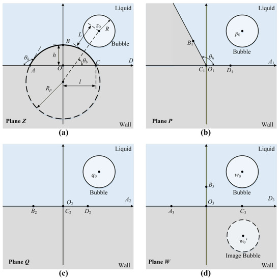
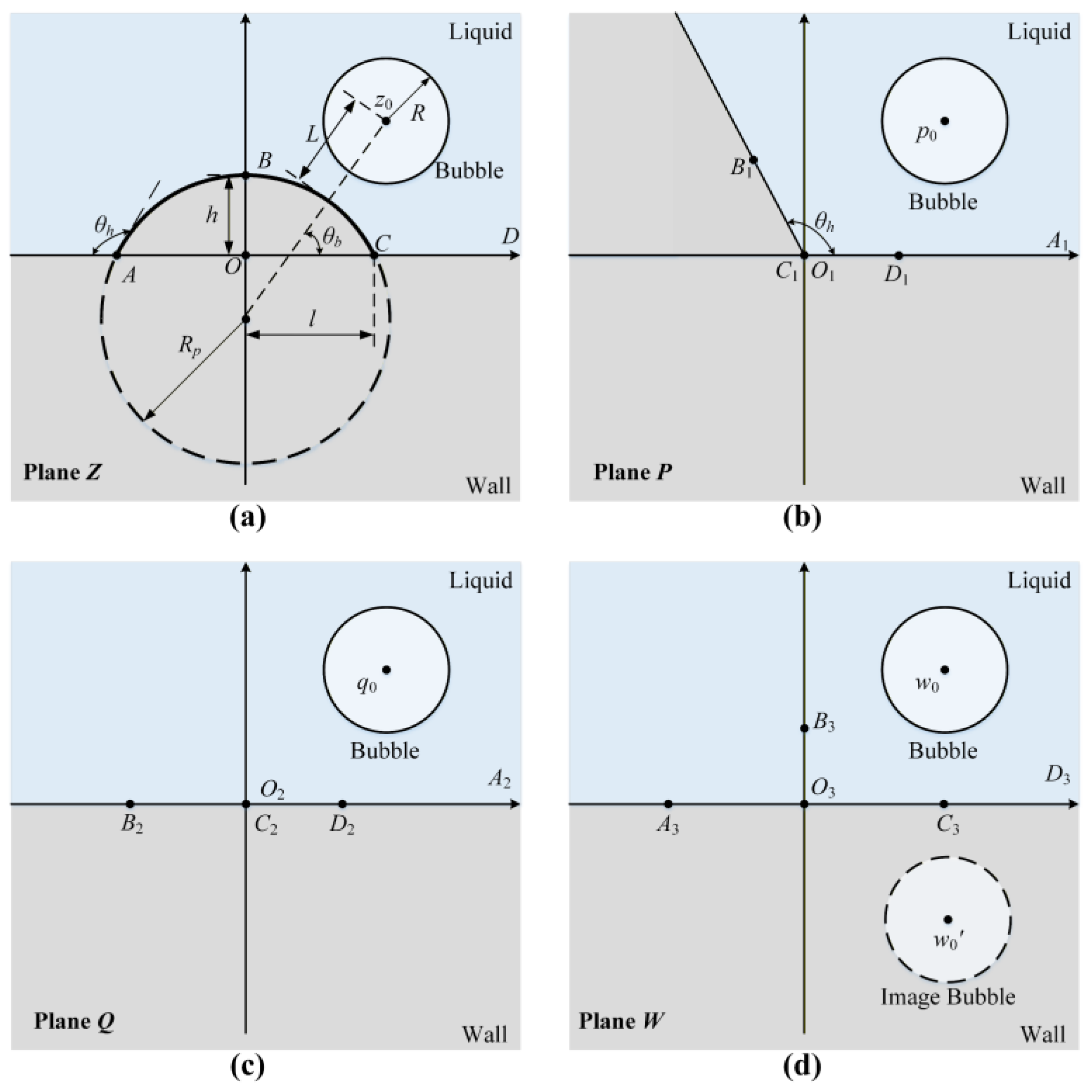
To calculate the additional velocity potential of the fluid, the wall surface should be treated accordingly. Here, the protrusion on the flat wall is considered as a portion of a cylinder. By utilizing the conformal transformation, the boundary of the flat wall with a protrusion can be transformed into a simple straight wall. Figure 1 illustrates the wall-processing procedure. First, a fractional linear transformation is utilized to transform the protruding flat wall boundary in plane Z into a corner wall in plane P. Then, a power function transformation is utilized to transform the corner wall into a flat wall in plane Q. Finally, a fractional linear transformation is utilized to transform the coordinates of each feature point back to their initial positions. The expressions for the three transformations are given as follows:
Figure 1.
Process diagram for boundary treatment with protruding wall surface. The gray and light blue areas represent the liquid and the wall, respectively. (a) Plane Z; (b) plane P; (c) plane Q; (d) plane W.
Here, is half the length of the protruding chord, and represents the angle between the tangent line at the protruding edge and the flat wall surface.
During the conformal transformation process, the coordinate of the two-dimensional point source is successively transformed into , , and , while its intensity remains unchanged.
The complex potential in plane W can be calculated as follows:
Here, is the complex conjugate of .
The expression for the fluid complex potential near the flat wall with a protrusion surface in plane Z is obtained below:
Subsequently, the additional complex potential is presented as follows:
The additional fluid velocity potential is expressed as:
And, the fluid velocity can be presented as:
Here, is the fluid velocity, and and represent the unit vectors of the x-axis and y-axis, respectively. When performing theoretical calculations, the values of parameters are shown in Table 1.
Table 1.
Values of parameters.
3. Experimental Setup
In this section, the experimental system and procedures are introduced, and the typical experimental phenomena are demonstrated.
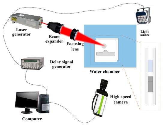
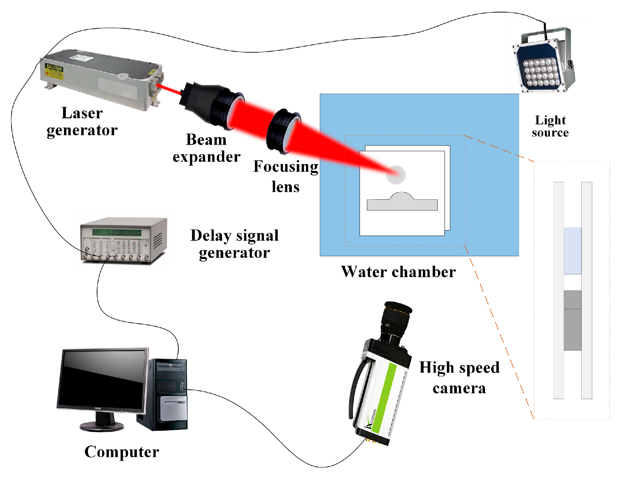
Figure 2 shows the layout and connection configuration of the experimental equipment. The water chamber contains deionized water, and the parallel glass plates are placed within it. During the experiment, the laser generator produces a laser beam. The beam passes through a beam expander and a focusing lens, and then converges between two parallel glass plates, forming a cylindrical bubble near the protruding wall. The delay signal generator is utilized to control the triggering of the laser generator and the camera for recording the bubble oscillation. The light source is utilized for fill lighting to ensure that the oscillations of the bubbles are clearly captured.
Figure 2.
Experimental system diagram.
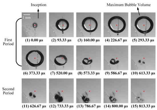
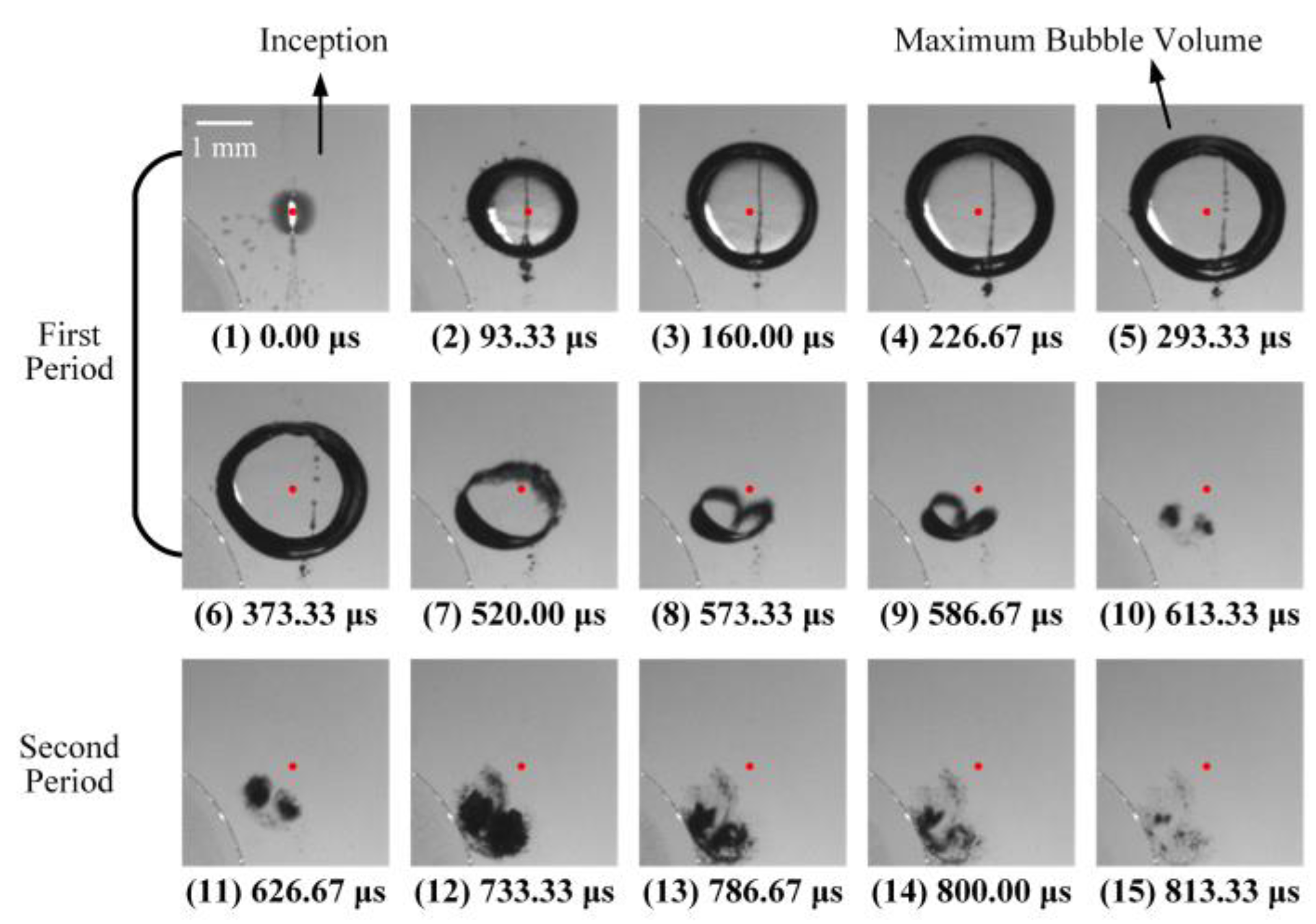
Figure 3 displays high-speed photographic images capturing typical experimental phenomena. The red dots represent the position of the bubble centroid. As shown in the figure, the bubble exhibits circular expansion during the growth (Figure 3(1)–(5)). During the collapse (Figure 3(6)–(10)), the side of the bubble closer to the protrusion contracts more slowly, while the side farther from the protrusion contracts more rapidly. In the latter stage of the collapse, a jet appears and points toward the protrusion (Figure 3(8)). Upon the completion of the first oscillation, the bubble separates into two clusters of different sizes (Figure 3(10)). Then, the two clusters rotate in the opposite directions, gradually approach the protrusion, and eventually collide with the wall surface.
Figure 3.
High-speed photographs of the bubble oscillation. The red dots indicate the bubble centroid at the inception moment.
To facilitate subsequent quantitative analysis, several dimensionless parameters have been defined as follows:
Here, and represent the radius and the height of the protrusion. denotes the distance between the bubble centroid and the protrusion surface. is the maximum bubble radius.
4. Collapse Jet Characteristics at Symmetrical Positions
In this section, the evolution of jet morphology during collapse at symmetric positions is analyzed, and the jet velocity is quantitatively analyzed.
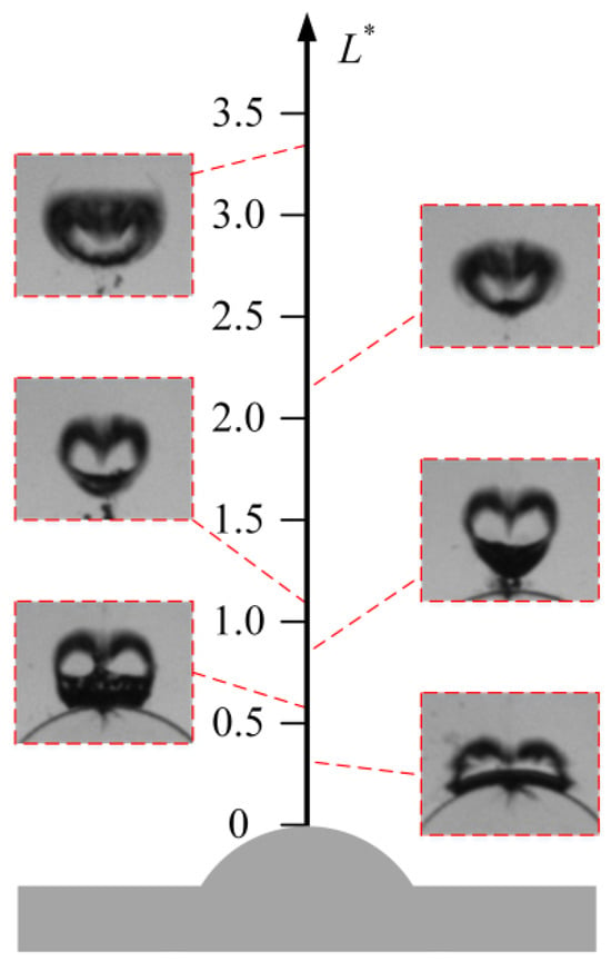
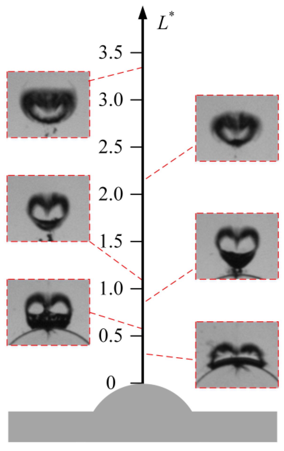
Figure 4 demonstrates the variation in the implosion jet morphology with the dimensionless distance. As shown in the figure, when the bubble is positioned near the protrusion (i.e., is small), it collapses in close proximity to the protrusion, forming a B-shaped configuration. As L* increases, the contraction rate of the bubble interface on the protrusion side slows down, causing the bubble to forming a heart-shaped configuration. As increases further, the protrusion’s effect on the bubble diminishes, causing the bubble to flatten into a cashew-shaped configuration.
Figure 4.
Variation in the bubble collapse jet morphology with dimensionless distance, .
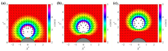
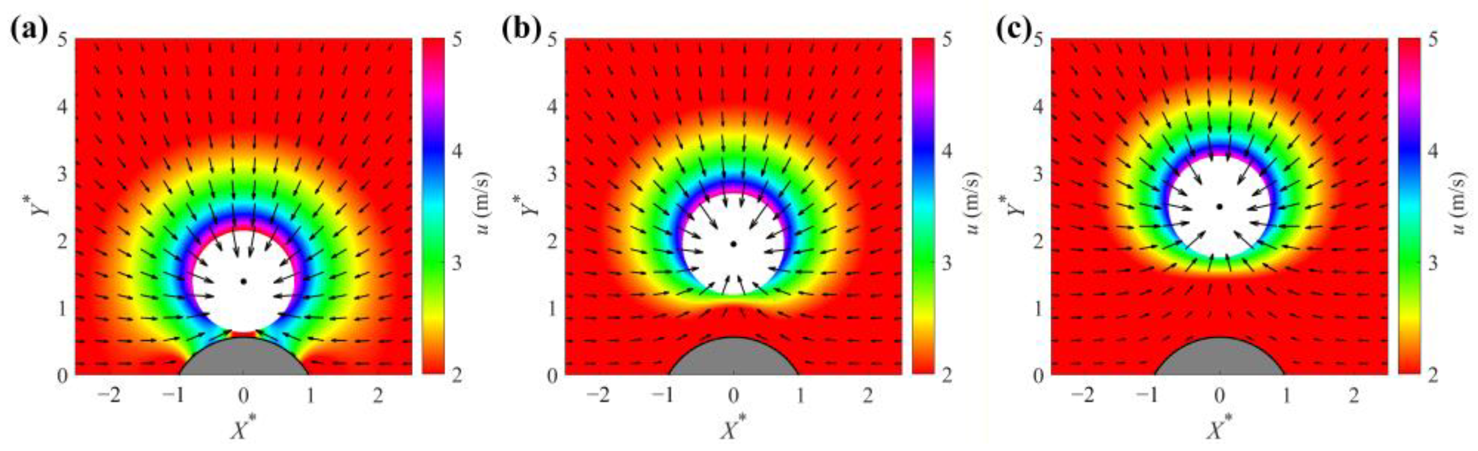
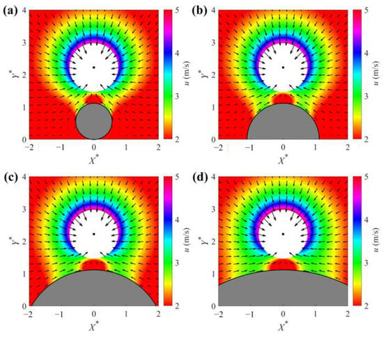
To explain the bubble jet morphology, the velocity distribution near the protrusion is analyzed. Figure 5 shows the velocity distribution near the protrusion at = 0.75. The gray areas in the figure represent protrusions, while the white areas indicate bubbles. Different colors denote the fluid velocity intensity, and the arrows indicate the velocity direction. As shown in the figure, a high-speed zone surrounds the bubble surface facing away from the protrusion, whereas a low-velocity area is present in the space separating the bubble and the protrusion. With an increase in the dimensionless distance (), the area of the low-velocity region grows larger. The velocity difference around the bubble diminishes, resulting in a weakened jet intensity. This phenomenon corresponds to the observations depicted in Figure 4.
Figure 5.
The fluid velocity distribution. The arrows indicate the direction and magnitude of the liquid velocity at the corresponding position. The dots indicate the position of the bubble centroid. X* and Y* represent the dimensionless coordinates. (a) = 0.83; (b) = 1.39; (c) = 1.94.
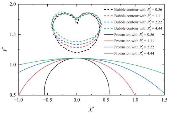
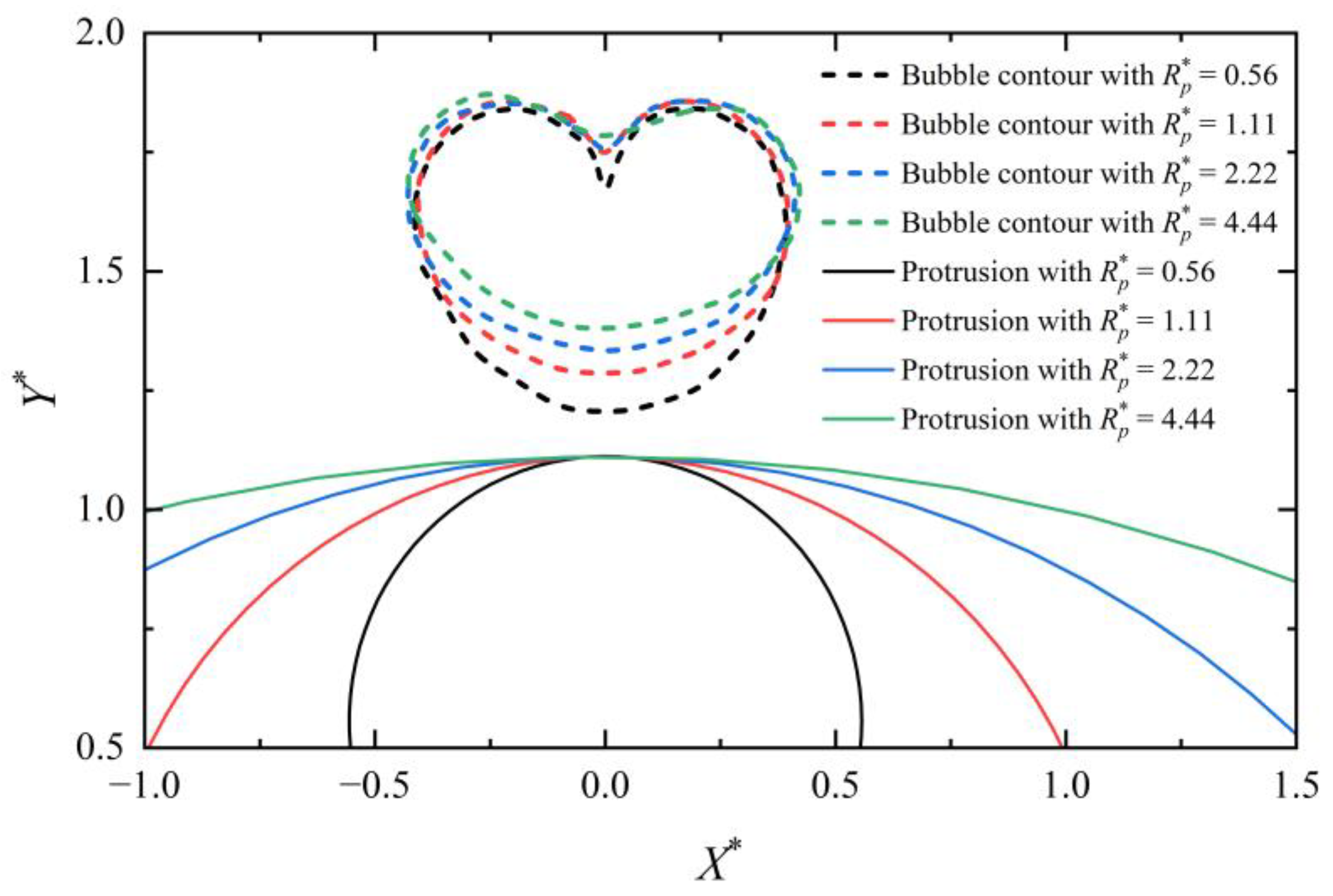
Subsequently, the effect of the protrusion radius on the jet is analyzed. Figure 6 demonstrates the bubble contours during the collapse with different protrusion radii. The dashed lines represent the bubble contours, while the solid lines represent the protrusions. As shown in the figure, with the increasing protrusion radius, the curvature of the bubble contour near the protrusion gradually decreases during the collapse, causing the bubble to evolve from the heart shape to the cashew shape.
Figure 6.
Bubble contours during the collapse with different protrusion radii. * is the symbol of dimensionless parameters.
Thereafter, the velocity distribution near protrusions with different radii is analyzed. Figure 7 illustrates the velocity distribution near the protrusion at = 0.75. The figure demonstrates that the low-velocity zone located between the bubble and the protrusion progressively widens as the radius of the protrusion increases. The high-speed zones adjacent to the low-velocity area also gradually expand, which aligns with the observed reduction in the curvature of the bubble wall near the protrusion during the collapse phase, as shown in Figure 6.
Figure 7.
The fluid velocity distribution near the protruding wall. The arrows indicate the direction and magnitude of the liquid velocity at the corresponding position. The dots indicate the position of the bubble centroid. X* and Y* represent the dimensionless coordinates. (a) = 0.56; (b) = 1.11; (c) = 2.22; (d) = 4.44.
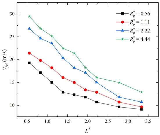
Figure 8 represents the variation in the jet velocity along the y-axis. The different-colored lines in the figure represent the results with different protrusion radii. The jet velocity decreases with the increasing . As the protrusion radius increases, its influence on the bubble intensifies, causing the jet velocity to rise and the rate of decrease with to become steeper.
Figure 8.
Variation in the jet velocity with the dimensionless distance. * is the symbol of dimensionless parameters.
5. Bubble Collapse Characteristics at Asymmetrical Positions
In this section, the bubble collapse characteristics at the asymmetrical are analyzed. The collapse jet and the bubble contour movement velocity are analyzed qualitatively and quantitively.
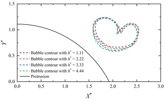
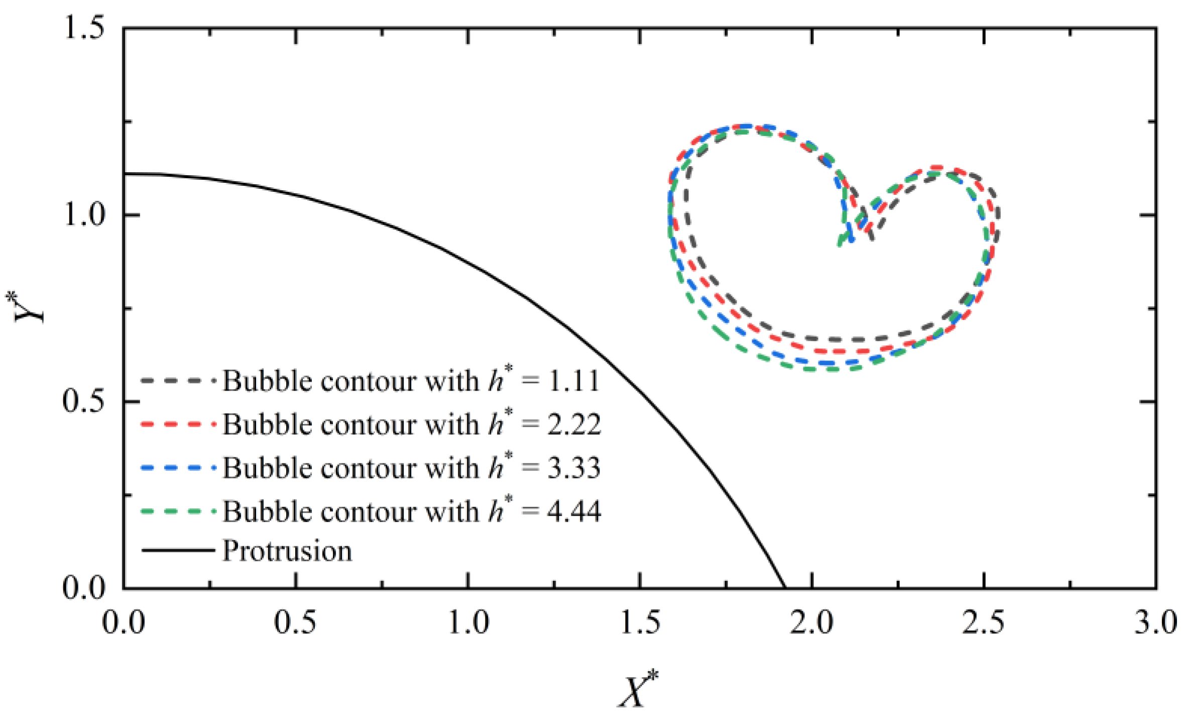
Figure 9 shows the bubble contours in the final stage of the collapse. In the figure, the solid line represents the protrusion, and the dashed lines of different colors represent the bubble contours with different protrusion heights (). When = 1.11, the bubble collapse is less affected by the protrusion, and the jet direction is almost vertically downward. As the height of the protrusion increases, the shape of the bubble collapse is also affected by the protrusion, and the jet direction gradually shifts towards the protrusion.
Figure 9.
The bubble contours during the collapse near the protrusions of different heights. * is the symbol of dimensionless parameters.
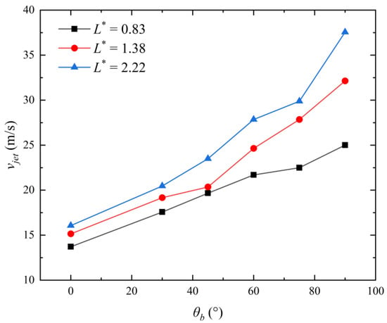
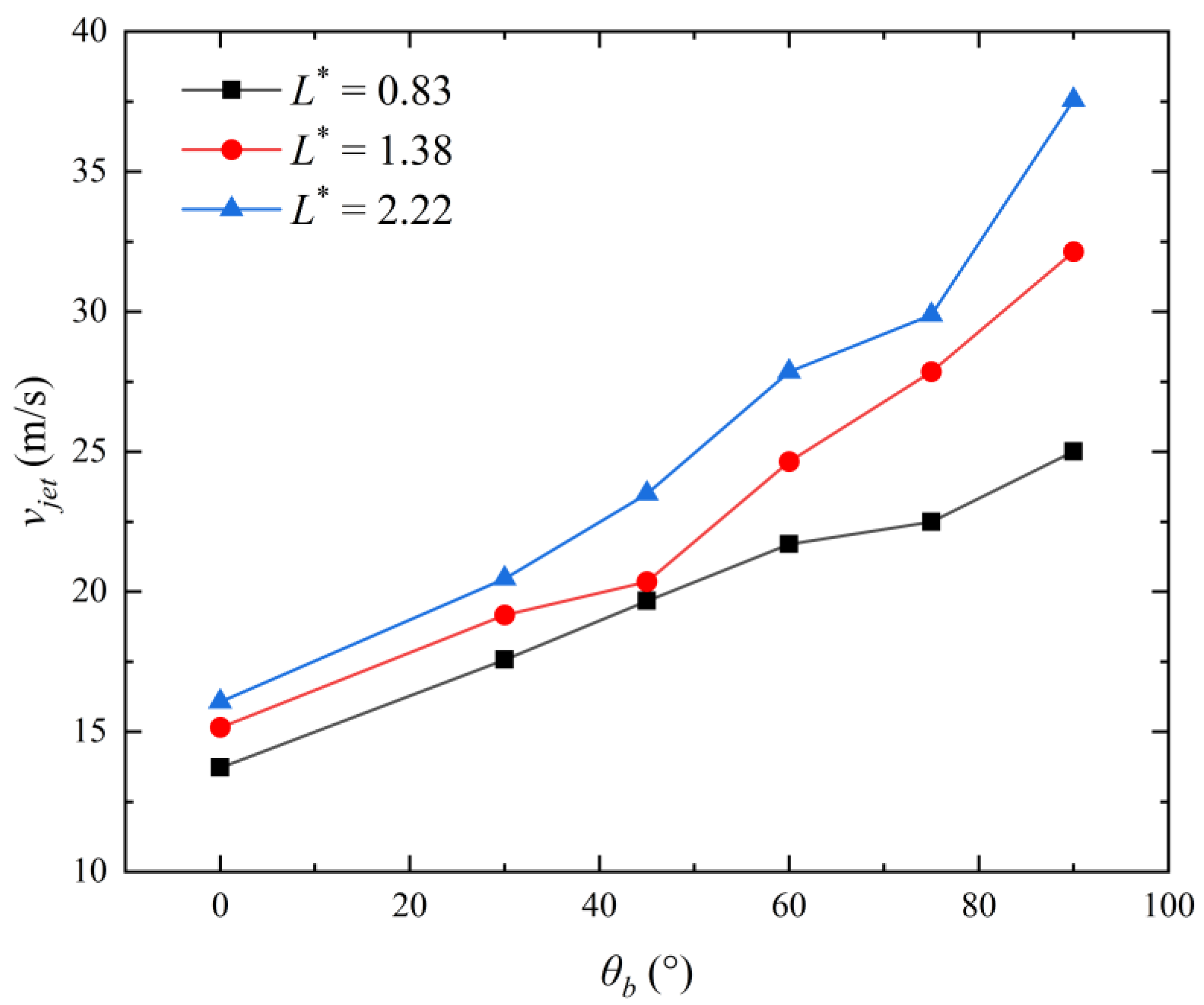
Subsequently, the influence of the bubble position angle () on the jet velocity is further analyzed. Figure 10 illustrates how the velocity of the bubble jet changes in relation to the bubble’s position angle. In the figure, the different-colored lines represent the results of different dimensionless distances (). Across three distinct distances, the jet velocity rises as the bubble’s position angle becomes larger. The highest bubble jet velocity is observed when the bubble’s position angle reaches 90°. In addition, as increases, the bubble jet velocity also increases.
Figure 10.
Variation in jet velocity with the position angle. * is the symbol of dimensionless parameters.
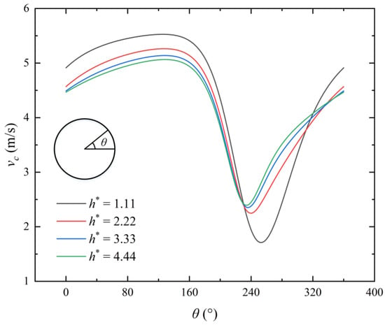
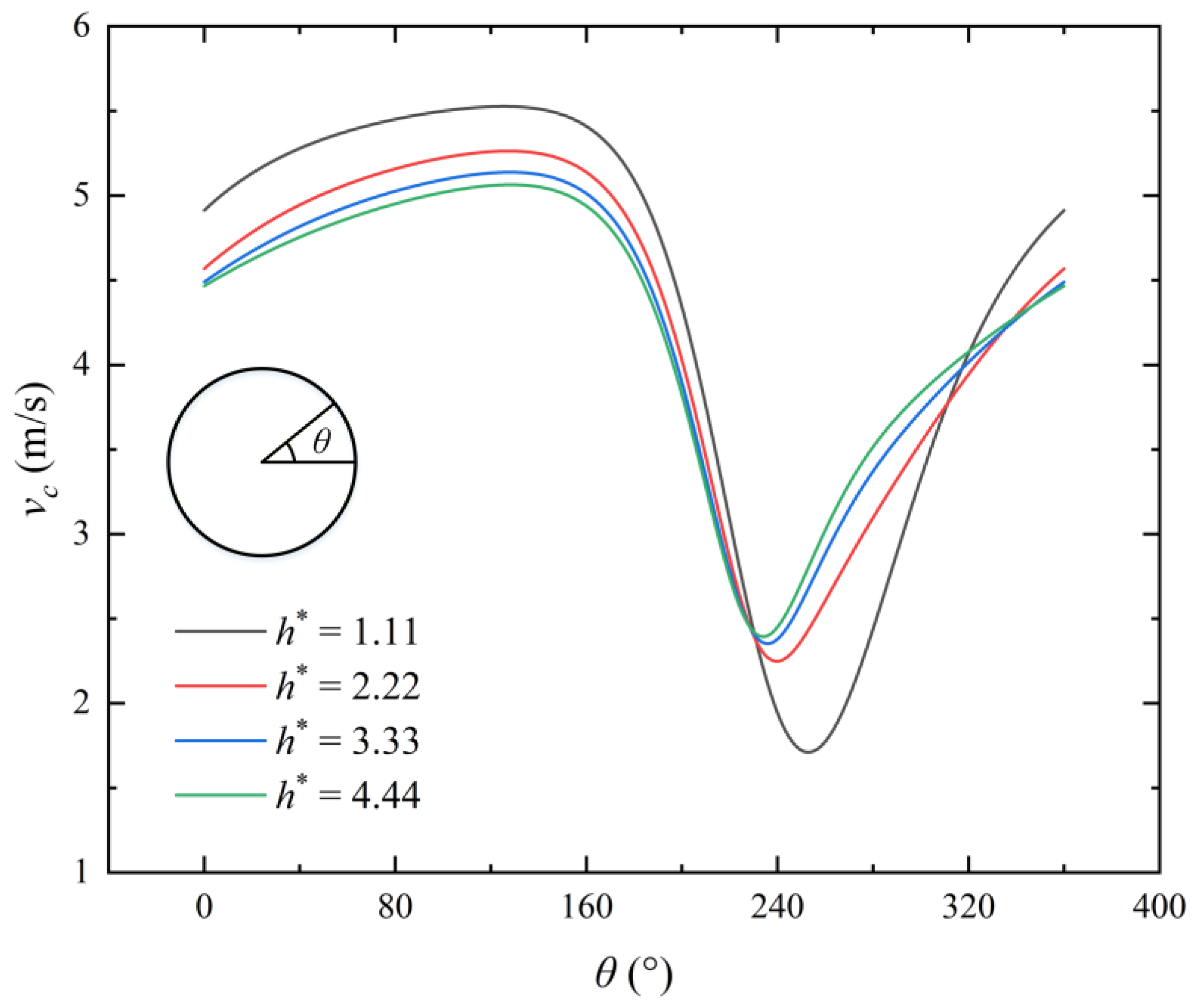
Figure 11 illustrates the liquid velocity distribution with the circumference angle, . The solid lines of different colors represent the results of different protrusion heights. The bubble circumference angle () is described in the figure. The pattern of liquid velocity change remains consistent across various protrusion heights. At ≈ 160°, the liquid velocity attains its maximum value, and at ≈ 240°, it reaches its minimum value. As decreases, the highest liquid velocity rises, while the lowest liquid velocity drops.
Figure 11.
Liquid velocity distribution with the circumference angle, . * is the symbol of dimensionless parameters.
6. The Analysis of the Bubble Centroid Movement
This section analyzes the characteristics of the Kelvin impulse near the protrusion, and contrasts them with the bubble centroid movement.
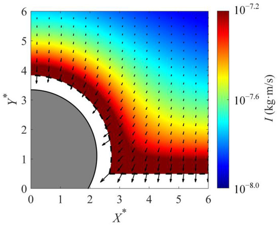
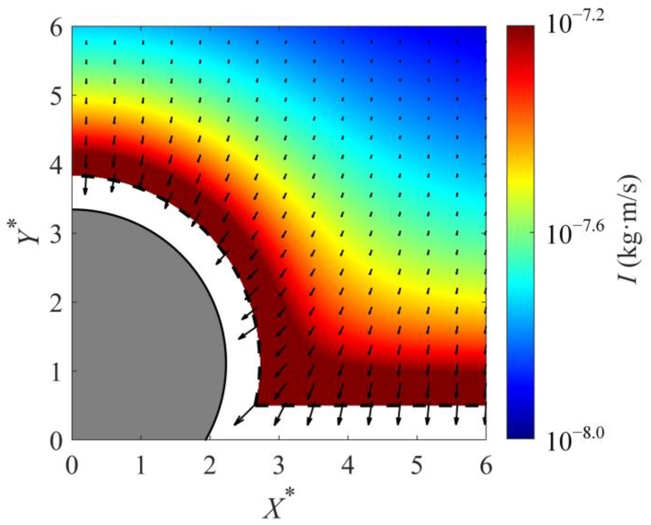
Figure 12 illustrates the Kelvin impulse distribution near the protrusion. The colors represent the Kelvin impulse intensity. The difference between the Kelvin impulse and liquid velocity is that its equation does not take into account the contribution of the bubble, and the impulse only comes from the protrusion. Therefore, the Kelvin impulse at a given location indicates both the strength and orientation of the impulse applied to the bubble at that specific point. As shown in the figure, as the distance from the protrusion increases, the Kelvin impulse gradually decreases.
Figure 12.
Kelvin impulse field diagram. The arrows indicate the direction and magnitude of the Kelvin impulse at the corresponding position. X* and Y* represent the dimensionless coordinates.
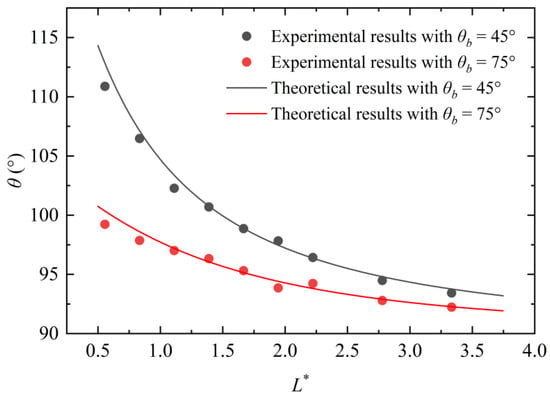
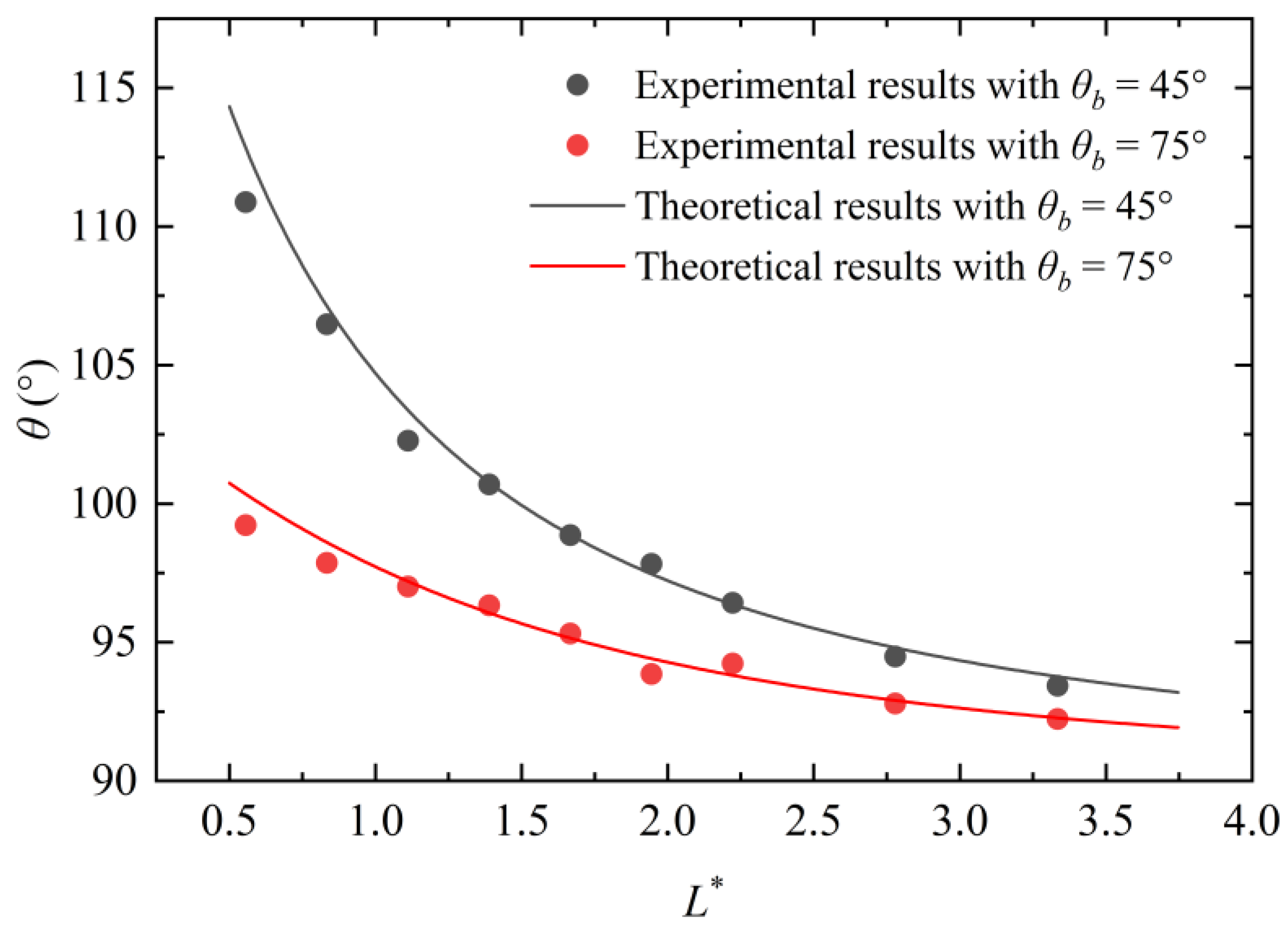
Figure 13 presents the variation in the Kelvin impulse directions and the bubble centroid movement directions with the dimensionless distance. In the figure, the lines represent the Kelvin impulse direction, and the dots represent the bubble centroid movement direction. The orientation of the Kelvin impulse aligns closely with the bubble centroid movement direction; both decrease with the increasing and .
Figure 13.
Variation in the Kelvin impulse directions and the bubble centroid movement directions with the dimensionless distance. * is the symbol of dimensionless parameters.
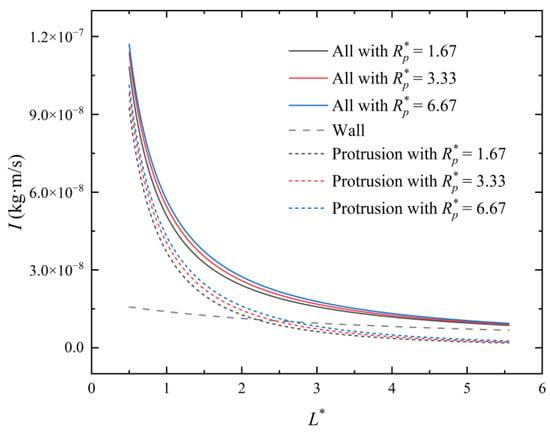
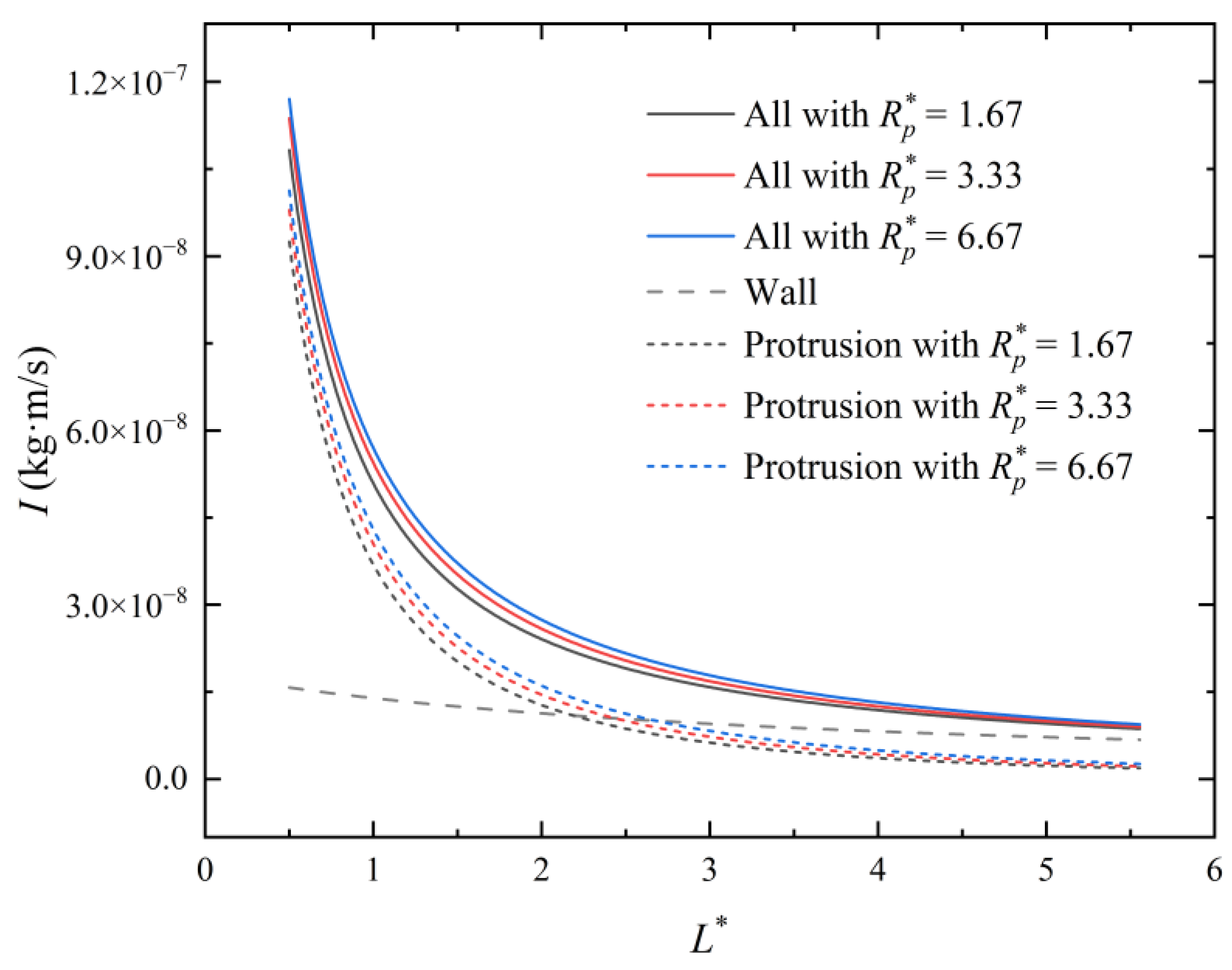
Subsequently, the influence mechanism of the Kelvin impulse is explored. Figure 14 illustrates the contributions of the protrusion and the flat wall. The different-colored lines represent the Kelvin impulse intensity of different dimensionless protrusion radii, and the dashed lines represent the results of the wall and the protrusion. As shown in the figure, when is small, the contribution of the protrusion is greater. When increases, the contributions of the protrusion and the flat wall decrease, while the flat wall’s contribution gradually becomes dominant.
Figure 14.
Contributions of the protrusion and the flat wall to the Kelvin impulse. * is the symbol of dimensionless parameters.
7. Conclusions
This study performs a systematic investigation into the dynamic characteristics of bubbles in the vicinity of a flat wall that features a protrusion inside a slit. Firstly, a qualitative examination is performed on the typical experimental observations of bubble growth and collapse. Then, the bubble collapse jet characteristics at symmetric and asymmetric positions are analyzed theoretically and experimentally. Finally, the Kelvin impulse characteristics are quantitatively analyzed and compared with the experimental results of the bubble centroid movement. The conclusions are given as follows:
- (1)
- At the symmetrical positions, the direction of the bubble jet is vertically downward. The jet velocity diminishes as the bubble–wall distance increases. It also decreases when the protrusion radius becomes smaller.
- (2)
- At the asymmetric positions, as the height of the protrusion increases, the jet direction gradually shifts towards the protrusion. And, the jet velocity increases with the increasing bubble position angle and the bubble–wall distance.
- (3)
- The Kelvin impulse direction is well consistent with the bubble centroid movement direction; both decrease with the increasing bubble–wall distance and bubble position angle.
By analyzing the bubble dynamics and influencing mechanisms near uneven wall surfaces within slits, this work provides guidance and recommendations for controlling micro-flow phenomena in such confined spaces.
Author Contributions
Conceptualization, G.W. and Y.Z.; methodology, G.W., Z.C. and H.B.; software, W.X., H.S. and J.H.; formal analysis, G.W., X.W. and X.Q.; supervision, Y.Z.; writing—original draft, G.W., H.S. and Z.C.; writing—review and editing, Y.Z. and Z.C.; project administration, Y.Z.; funding acquisition, X.W. and Y.Z. All authors have read and agreed to the published version of the manuscript.
Funding
This work was financially supported by the National Natural Science Foundation of China (52506046), the Fundamental Research Funds for the Central Universities (2025MS015), the China Postdoctoral Science Foundation under Grant Number 2025M770612, and the Postdoctoral Fellowship Program of CPSF under Grant Number GZC20240466.
Institutional Review Board Statement
Not applicable.
Informed Consent Statement
Not applicable.
Data Availability Statement
Data available on request from the authors.
Conflicts of Interest
Xu Qiu is employed by China Atomic Energy Publishing & Media Company Limited. The remaining authors declare that the research was conducted in the absence of any commercial or financial relationships that could be construed as a potential conflict of interest.
References
- Gao, G.; Guo, S.; Li, D. A Review of Cavitation Erosion on Pumps and Valves in Nuclear Power Plants. Materials 2024, 17, 1007. [Google Scholar] [CrossRef] [Scilit]
- Ouyang, T.; Li, Y.; Tian, H.; Wang, J.; Zhang, N. Cavitation Mechanism of High-Speed Helical Gears Induced by Vibration. Tribol. Int. 2024, 193, 109440. [Google Scholar] [CrossRef] [Scilit]
- Abbasi, A.A.; Franzosi, G.; Viviani, M.; Bertetta, D.; Tani, G. Experimental Analysis of Blade Root Cavitation Erosion on Set of Model Propellers. Ocean Eng. 2024, 311, 118766. [Google Scholar] [CrossRef] [Scilit]
- Wu, X.; Hu, J.; Wang, J.; Wang, Z.; Zhang, Y. Vortex Dynamics and Wall Shear Stress from Bubble Collapse near a Particle and a Wall. J. Hydrodyn. 2025, 37, 266–280. [Google Scholar] [CrossRef] [Scilit]
- Zarzycki, E. Innovation Report: A Methodology for Estimating Gear Pump Wear-out Reliability Using Pump Pressure Ripple and an Extremely Small Sample Size—The Case Study of a Heavy-Duty Diesel Engine Lubrication Gear Pump. Ph.D. Thesis, University of Warwick, Coventry, UK, 2020. [Google Scholar]
- Gonzalez-Parra, J.C.; Robles, V.; Devia-Cruz, L.F.; Rodriguez-Beltran, R.I.; Cuando-Espitia, N.; Camacho-Lopez, S.; Aguilar, G. Mitigation of Cavitation Erosion Using Laser-Induced Periodic Surface Structures. Surf. Interf. 2022, 29, 101692. [Google Scholar] [CrossRef] [Scilit]
- Caupin, F.; Herbert, E. Cavitation in Water: A Review. Comptes Rendus Phys. 2006, 7, 1000–1017. [Google Scholar] [CrossRef] [Scilit]
- Lu, Z.; Gu, J.; Zhang, P.; Luo, C.; Ren, X. Investigation on Laser Cavitation Micro-Forming Process: Deformation Behavior of 1060 Aluminum Foil and Bubble Evolution in a Gap. J. Manuf. Process. 2021, 67, 619–627. [Google Scholar] [CrossRef] [Scilit]
- Ma, S.; Shen, J.; Ying, J.; Zhang, S.; Zhang, Y.; Zhang, Y. Research on the Bubble Collapse Behaviors near Dual Cylinders within Confined Spaces. J. Hydrodyn. 2024, 36, 1021–1032. [Google Scholar] [CrossRef] [Scilit]
- Zhang, H.; Fan, C.; Wang, L.; Lu, W.; Li, D. The Generation Methods and Applications of Cavitating Jet by Using Bubble Collapse Energy. Energies 2024, 17, 5902. [Google Scholar] [CrossRef] [Scilit]
- Yu, Y.; Cui, J.; Smith, W.R.; Wang, Q.; Leighton, T.G. The Mechanisms of Jetting, Vortex Sheet, and Vortex Ring Development in Asymmetric Bubble Dynamics. Phys. Fluids 2023, 35, 123320. [Google Scholar] [CrossRef] [Scilit]
- Yang, X.; Liu, C.; Hu, Y.; Zhao, M.; Hu, C. Shock Wave Induced by the Collapse of a Bubble Cluster with Each Bubble Distributed Randomly. Ocean Eng. 2024, 300, 117362. [Google Scholar] [CrossRef] [Scilit]
- Ouyang, T.; Wang, J.; Mo, X.; Li, Y. Vibration and Cavitation in High-Speed Gears Caused by Faults. Int. J. Mech. Sci. 2023, 250, 108322. [Google Scholar] [CrossRef] [Scilit]
- Xu, W.; Li, J.; Luo, J.; Zhai, Y. Effect of a Single Air Bubble on the Collapse Direction and Collapse Noise of a Cavitation Bubble. Exp. Therm Fluid Sci. 2021, 120, 110218. [Google Scholar] [CrossRef] [Scilit]
- Aganin, A.A.; Kosolapova, L.A.; Malakhov, V.G. Bubble Dynamics near a Locally Curved Region of a Plane Rigid Wall. Phys. Fluids 2022, 34, 097105. [Google Scholar] [CrossRef] [Scilit]
- Liu, Y.; Liu, Y.; Duan, J.; Hu, J.; Zhang, Y.; Wang, X.; Gao, D.; Zhang, Y. Numerical Investigation of the Needle Jets Produced by Cavitation Bubbles near a Concave Wall. J. Mech. Sci. Technol. 2025, 39, 1235–1245. [Google Scholar] [CrossRef] [Scilit]
- Shervani-Tabar, M.T.; Rouhollahi, R. Numerical Study on the Effect of the Concave Rigid Boundaries on the Cavitation Intensity. Sci. Iran. 2017, 24, 1958–1965. [Google Scholar] [CrossRef] [Scilit]
- Han, D.; Park, S.; Duy-Trong, N.; Nguyen, V.; Sagar, H.; Moctar, O.E.; Phan, T.-H.; Park, W.-G. Dynamics of a Single Cavitation Bubble near a Cylindrical Blind Hole. Ocean Eng. 2024, 311, 118890. [Google Scholar] [CrossRef] [Scilit]
- Trummler, T.; Bryngelson, S.H.; Schmidmayer, K.; Schmidt, S.J.; Colonius, T.; Adams, N.A. Near-Surface Dynamics of a Gas Bubble Collapsing above a Crevice. J. Fluid Mech. 2020, 899, A16. [Google Scholar] [CrossRef] [Scilit]
- Zargarzadeh, L.; Elliott, J.A.W. Bubble Formation in a Finite Cone: More Pieces to the Puzzle. Langmuir 2019, 35, 13216–13232. [Google Scholar] [CrossRef] [Scilit]
- Dadvand, A.; Manmi, K.M.A.; Aziz, I.A. Three-Dimensional Bubble Jetting inside a Corner Formed by Rigid Curved Plates: Boundary Integral Analysis. Int. J. Multiphase Flow. 2023, 158, 104308. [Google Scholar] [CrossRef] [Scilit]
- Cui, J.; Chen, Z.; Wang, Q.; Zhou, T.; Corbett, C. Experimental Studies of Bubble Dynamics inside a Corner. Ultrason. Sonochem. 2020, 64, 104951. [Google Scholar] [CrossRef] [Scilit]
- Li, S.; Liu, Y.; Wang, Q.; Zhang, A. Dynamics of a Buoyant Pulsating Bubble near Two Crossed Walls. Phys. Fluids 2021, 33, 073310. [Google Scholar] [CrossRef] [Scilit]
- Liu, J.; Wang, T.; Che, Z. Dynamics of Cavitation Bubbles inside a Small Corner. Phys. Fluids 2025, 37, 012106. [Google Scholar] [CrossRef] [Scilit]
- Wang, Q.; Mahmud, M.; Cui, J.; Smith, W.R.; Walmsley, A.D. Numerical Investigation of Bubble Dynamics at a Corner. Phys. Fluids 2020, 32, 053306. [Google Scholar] [CrossRef] [Scilit]
- Tagawa, Y.; Peters, I.R. Bubble Collapse and Jet Formation in Corner Geometries. Phys. Rev. Fluids 2018, 3, 081601. [Google Scholar] [CrossRef] [Scilit]
- Andrews, E.D.; Rivas, D.F.; Peters, I.R. Cavity Collapse near Slot Geometries. J. Fluid Mech. 2020, 901, A29. [Google Scholar] [CrossRef] [Scilit]
- Požar, T.; Petkovšek, R. Cavitation Induced by Shock Wave Focusing in Eye-like Experimental Configurations. Biomed. Opt. Express 2019, 11, 432–447. [Google Scholar] [CrossRef] [Scilit]
- Kim, D.; Kim, D. Underwater Bubble Collapse on a Ridge-Patterned Structure. Phys. Fluids 2020, 32, 053312. [Google Scholar] [CrossRef] [Scilit]
- Kadivar, E.; el Moctar, O.; Sagar, H.J. Experimental Study of the Influence of Mesoscale Surface Structuring on Single Bubble Dynamics. Ocean Eng. 2022, 260, 111892. [Google Scholar] [CrossRef] [Scilit]
- Ma, C.; Shi, D.; Chen, Y.; Cui, X.; Wang, M. Experimental Research on the Influence of Different Curved Rigid Boundaries on Electric Spark Bubbles. Materials 2020, 13, 3941. [Google Scholar] [CrossRef] [Scilit]
- Li, S.; Zhang, A.-M.; Han, R. Letter: Counter-Jet Formation of an Expanding Bubble near a Curved Elastic Boundary. Phys. Fluids 2018, 30, 121703. [Google Scholar] [CrossRef] [Scilit]
- Kadivar, E.; Phan, T.-H.; Park, W.-G.; el Moctar, O. Dynamics of a Single Cavitation Bubble near a Cylindrical Rod. Phys. Fluids 2021, 33, 113315. [Google Scholar] [CrossRef] [Scilit]
- Koch, M.; Rosselló, J.M.; Lechner, C.; Lauterborn, W.; Mettin, R. Dynamics of a Laser-Induced Bubble above the Flat Top of a Solid Cylinder—Mushroom-Shaped Bubbles and the Fast Jet. Fluids 2022, 7, 2. [Google Scholar] [CrossRef] [Scilit]
- Li, B.; Jia, W.; Zhang, H.; Lu, J. Investigation on the Collapse Behavior of a Cavitation Bubble near a Conical Rigid Boundary. Shock Waves 2014, 24, 317–324. [Google Scholar] [CrossRef] [Scilit]
- Wang, Y.; Hu, S.; Feng, Z.; Liu, Y.; Wang, X.; Zhang, Y. Investigation on the Cylindrical Bubble Dynamics near a Wall with an Arched Bulge. J. Hydrodyn. 2024, 36, 1073–1082. [Google Scholar] [CrossRef] [Scilit]
- Mishra, A.; Mondal, J.; Roy, A.; Lakkaraju, R.; Ghosh, P. Effect of Curved Rigid Surface on the Collapsing Cavitating Bubble in Cryogenic Environment. IOP Conf. Ser. Mater. Sci. Eng. 2020, 755, 012067. [Google Scholar] [CrossRef] [Scilit]
- Nguyen, Q.-T.; Nguyen, V.-T.; Sagar, H.; el Moctar, O.; Park, W.-G. Effects of Oscillating Curved Wall on Behavior of a Collapsing Cavitation Bubble. Phys. Fluids 2025, 37, 013312. [Google Scholar] [CrossRef] [Scilit]
- Tomita, Y.; Robinson, P.B.; Tong, R.P.; Blake, J.R. Growth and Collapse of Cavitation Bubbles near a Curved Rigid Boundary. J. Fluid Mech. 2002, 466, 259–283. [Google Scholar] [CrossRef] [Scilit]
- Zhao, J.; Bai, P.; Wang, J.; Wang, Y.; Cao, S. Dynamics of Bubble Collapse near Rigid Boundaries with Different Curvatures. Phys. Fluids 2025, 37, 033302. [Google Scholar] [CrossRef] [Scilit]
- Ilinskii, Y.A.; Zabolotskaya, E.A.; Hay, T.A.; Hamilton, M.F. Models of Cylindrical Bubble Pulsation. J. Acoust. Soc. Am. 2012, 132, 1346–1357. [Google Scholar] [CrossRef] [Scilit]
- Best, J.P.; Blake, J.R. An Estimate of the Kelvin Impulse of a Transient Cavity. J. Fluid Mech. 1994, 261, 75–93. [Google Scholar] [CrossRef] [Scilit]

Disclaimer/Publisher’s Note: The statements, opinions and data contained in all publications are solely those of the individual author(s) and contributor(s) and not of MDPI and/or the editor(s). MDPI and/or the editor(s) disclaim responsibility for any injury to people or property resulting from any ideas, methods, instructions or products referred to in the content. |
© 2026 by the authors. Licensee MDPI, Basel, Switzerland. This article is an open access article distributed under the terms and conditions of the Creative Commons Attribution (CC BY) license.