


Abstract
For arch dam seismic safety evaluation, the finite element equivalent stress method has been widely used, and existing studies have realized mature equivalent stress calculation along the foundation surface path. However, from the scientific research perspective, there is a lack of a full dam surface equivalent stress characterization method for arch dams under seismic action; from the engineering practice perspective, the traditional path method cannot fully reflect the overall stress distribution of the dam, leading to insufficient comprehensive safety evaluation. To accurately assess the impact of seismic action on the overall structural safety of arch dams and address the above limitations, this study develops a methodology for calculating equivalent stress across the entire dam surface of arch dams under seismic action. Taking a concrete arch dam as the research object, a seismic wave input method based on viscoelastic artificial boundaries is employed. Three-dimensional finite element analysis of the arch dam is performed using ABAQUS, integrated with Python-based secondary development to extract stress along the integration path of each arch ring layer and calculate sectional internal forces. The equivalent stress of each arch ring layer integration path is then processed using the material mechanics method to obtain the equivalent stress distribution across the entire dam surface. A comparative analysis is conducted between the equivalent stress on the entire dam surface and that along paths on the foundation surface regarding the seismic dynamic response and behavioral patterns of the dam. The results demonstrate that the full dam surface equivalent stress approach not only accurately captures the extreme tensile and compressive stress values in the downstream foundation area but also identifies stress extrema in the upstream dam crest region, thereby achieving comprehensive characterization of the dam stress field under seismic action and enhancing both the efficiency and accuracy of equivalent stress calculations for arch dams. This method provides more comprehensive and reliable data support for seismic design optimization and reinforcement of arch dams. Compared with the traditional foundation surface path method, the proposed method achieves 100% identification of the whole dam surface stress extremum areas, with a maximum relative error of only 1.62% in the overlapping calculation area.
1. Introduction
As a typical spatial shell structure, arch dams exhibit complex stress states in the dam body. The finite element method has been extensively applied in arch dam stress analysis due to its strong applicability and other advantages [1,2,3,4,5,6,7,8]. However, when using the finite element analysis method to study the stress conditions of arch dams, significant stress concentration phenomena occur near the foundation region of the dam body, and stress values increase with mesh refinement. In actual engineering practice, various micro-cracks and plastic properties exist within the concrete dam body and rock foundation, which substantially mitigate the degree of stress concentration. Therefore, the stress concentration at the arch dam foundation surface, as reflected by the finite element method, often deviates from actual conditions [9,10,11]. Inaccurate arch dam stress analysis results will directly lead to insufficient structural design, potentially inducing dam cracking, overall instability and even catastrophic dam break accidents with huge economic losses and casualties, which has become a major hidden danger to the safe operation of arch dam projects. To address this issue, equivalent stress is commonly employed in engineering for safety verification. Equivalent stress serves as a fictitious, linearized representation derived from strength theory, transforming a complex, multiaxial stress state at a specific point into an equivalent uniaxial value. This transformation facilitates a direct evaluation of structural integrity against the material’s uniaxial tensile and compressive strength limits. Building on this foundation, some domestic researchers have proposed the finite element equivalent stress method, an engineering calculation approach that combines finite element numerical analysis with strength theory criteria. Its core concept involves first, accurately obtaining complex stress components at various points of the structure through the finite element method; then performing integration operations along arch-cantilever sections to obtain internal forces; subsequently deriving the stress distribution pattern on sections using material mechanics analysis methods; and ultimately making calculation results more consistent with actual engineering conditions [12,13,14].
Based on this foundation, by conducting axial tensile tests, Zhang et al. [15] demonstrated that the equivalent stress of rectangular and elliptical induced joints—with elliptical ones showing slightly higher values—exhibits a linear negative correlation with the degree of weakening and concluded that implementing joints with the calculated equivalent stress of 1.409 MPa in high-tensile zones effectively releases thermal stresses to ensure overall structural safety. By utilizing coordinate transformations and internal force integration to derive equivalent stresses and alleviate concentration phenomena, Cai et al. [16] integrated the finite element equivalent stress method with an improved response surface method to evaluate the structural reliability of arch dams under freeze–thaw cycles. Wang et al. [17] employed the finite element equivalent stress method to synthesize concentrated stress at edge corners into corresponding linear equivalent stress after obtaining finite element analysis results for the Busanga arch dam. Liang Jian et al. improved the equivalent stress calculation program for mixed linear arch dams and verified its rationality by comparing the calculated maximum equivalent principal stress with results obtained from the arch-cantilever method. Cheng [18] performed three-dimensional finite element calculations of arch dams through ABAQUS to achieve local equivalent stress processing. However, the above equivalent stress calculations only achieved equivalent stress solutions on the foundation surface and cannot calculate the distribution of equivalent stress across the entire dam surface, lacking a systematic analysis of the overall stress state of arch dams. This path limitation will directly lead to inaccurate full-field stress analysis results and easily miss the high-risk areas of the dam body that may induce engineering accidents. Zhou et al. [19] studied the equivalent stress at the dam heel of high arch dams and proposed the finite element equivalent stress method, which can alleviate stress concentration with weak mesh dependency but only provides a linear generalization of stress. With 32 grid layers as the baseline, achieving errors of ≤5% requires at least 10 grid layers. When combined with finite element simulation, the stress variation patterns reflected in the calculation results are consistent with the measured stress variation patterns, providing a reference for the numerical analysis of dam heel stress.
Notably, arch dams, due to their structural characteristics, are often constructed in mountainous canyon regions, particularly in southwestern China, where geological structures are complex and seismic activity is frequent [20,21,22,23]. Seismic disasters may cause severe damage to arch dam structures; therefore, the seismic safety of arch dams has always been a key concern in the construction and operation of China’s water conservancy and hydropower projects [24,25]. Multi-dimensional seismic excitation and wave-structure interaction effects cause stress concentration phenomena to exhibit more widespread distribution characteristics. At the transitions of upstream and downstream dam faces, gradual changes in dam body thickness, and structural discontinuity zones such as gallery openings and joints, stress redistribution is easily triggered due to geometric discontinuity and stiffness mutations, leading to local stress peaks [26,27,28,29].
In recent years, the rapid development of smart hydraulic engineering, advanced sensing technology and digital twin theory has provided a new technical paradigm for the seismic safety assessment of arch dams while also putting forward higher requirements for the full-space characterization of dam stress fields. Modern monitoring methods for seismic loads have achieved significant breakthroughs: high-precision “intelligent” sensors represented by distributed fiber optic sensors, MEMS vibration sensors and wireless strain sensing networks have been widely used in the dynamic response monitoring of large hydraulic structures, realizing real-time, full-coverage acquisition of seismic excitation signals and dam stress–strain response data throughout the earthquake process. The core value of intelligent monitoring technology lies in the quantitative mapping between field-measured data and numerical calculation results, and this technical route has been fully verified in complex dynamic load assessment scenarios in related engineering fields [30,31,32,33,34]. On this basis, digital twin technology, which integrates physical entity modeling, real-time sensing data driving and high-fidelity numerical simulation, has become an important development direction for the whole life cycle seismic safety management of arch dams. However, the existing equivalent stress calculation methods for arch dams are mostly limited to the foundation surface path, which can only realize stress verification at discrete local monitoring points and cannot form full-space matching between numerical calculation results and full dam surface monitoring data from the intelligent sensing network, which restricts the deep application of digital twin technology in the seismic safety assessment of arch dams [35,36,37,38,39].
To sum up, the existing research has formed a mature theoretical system and engineering application scheme for the equivalent stress calculation of the foundation surface path of arch dams, but there are still obvious deficiencies in both scientific research and engineering practice. In terms of scientific research, the global characterization theory of arch dam equivalent stress covering the whole dam surface has not been established, and the distribution law of the full-field stress extremum of arch dams under seismic action cannot be systematically revealed. In terms of engineering application, the existing method is limited by the preset path, which makes it easy to miss the stress concentration risk in non-foundation surface areas such as dam crests under earthquakes, and cannot meet the requirements of a comprehensive seismic safety evaluation of arch dam engineering. This paper provides an effective calculation method for equivalent stress across the entire dam surface of arch dams—that is, the full-domain distribution state of equivalent stress at each calculation point on the entire exposed surface of the dam body—to improve the accuracy of full dam surface equivalent stress calculations and solve practical problems in arch dam stress assessment under seismic action. The high stress concentrations derived from linear elastic finite element analysis are essentially mesh-dependent numerical singularities that fail to reflect the actual stress state of a structure. In engineering practice, the presence of micro-cracks and localized plasticity within the concrete and bedrock facilitates stress redistribution in high-gradient zones, significantly alleviating the severity of stress concentration. Through an integration-linearization process based on the conservation of sectional internal forces, equivalent stress eliminates these numerical singularities without altering the total sectional loading. This approach equivalently reconstructs the practical engineering stress state following stress relaxation induced by localized nonlinear behaviors and remains the mainstream methodology for stress verification in arch dams. This study conducts three-dimensional finite element stress calculations based on specific engineering cases. By establishing an arch dam numerical model and applying interpolation calculation methods to process finite element results, a precise solution of equivalent stress across the entire dam surface is achieved. Through this technical approach, visualization of full dam surface equivalent stress contour maps can be rapidly generated, providing designers with intuitive stress distribution information, effectively assisting them in promptly determining whether dam body stress meets code-specified control standards, and significantly improving the efficiency and accuracy of arch dam stress analysis. This method fundamentally avoids the engineering safety risks caused by inaccurate equivalent stress analysis results and provides a technical means for the pre-control of hidden dangers in arch dam seismic safety.
2. Materials and Methods
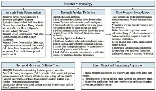
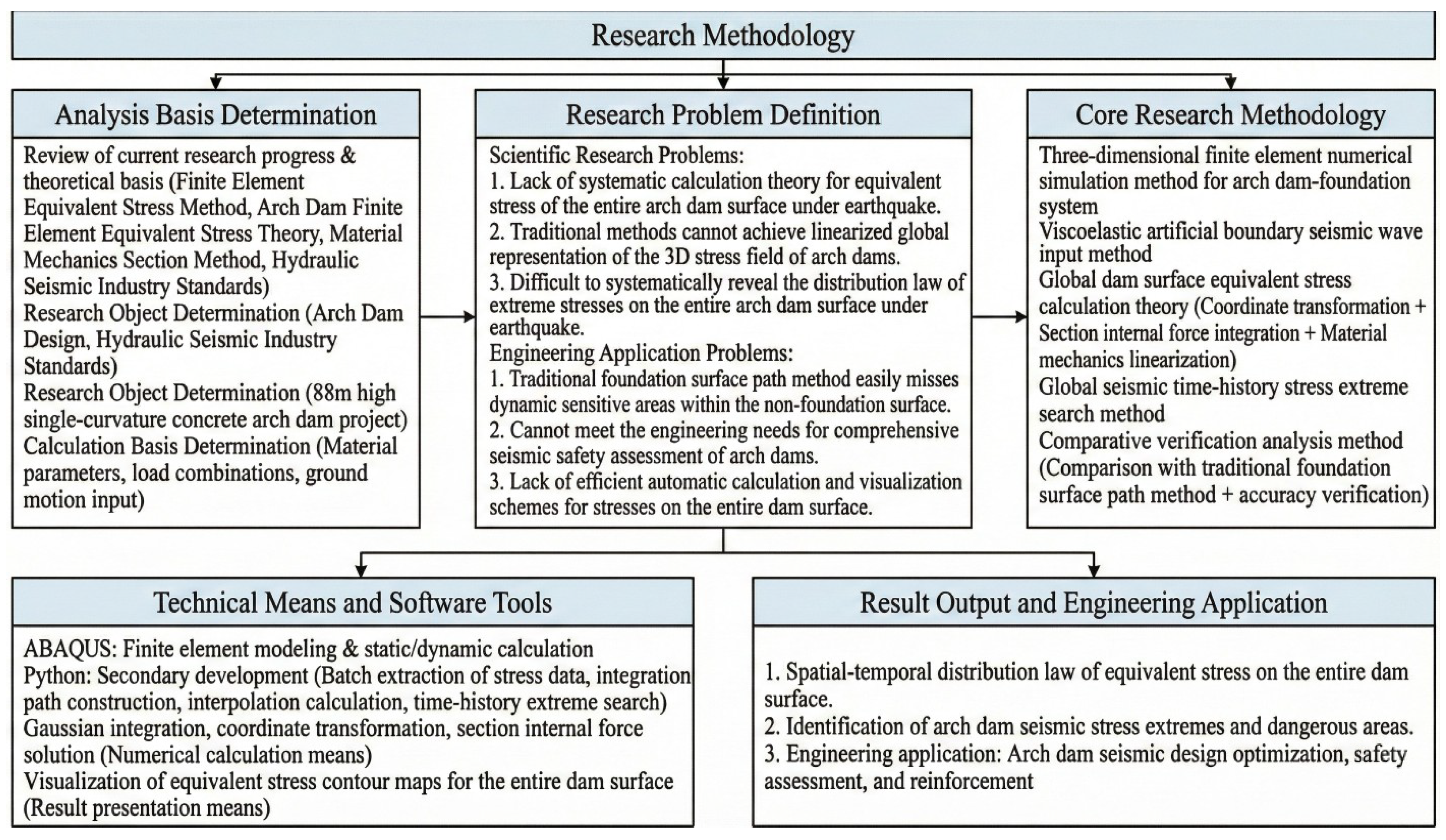
The overall technical framework and research workflow of this study are shown in Figure 1. This study is carried out based on the mature theory of arch dam equivalent stress analysis and current hydraulic engineering specifications. The whole research process includes four core links: analysis basis determination, research problem definition, core method implementation, and result verification and application. The specific implementation details of the core calculation method are described in the following sections.
Figure 1.
Research Methodology Flowchart.
2.1. Equivalent Stress Calculation
Equivalent stress [40,41,42] is a mechanical indicator that converts the complex multi-axial stress state within a component into a single scalar value. For arch dam structures, based on the internal force calculation results of the arch-cantilever system and employing material mechanics analysis methods, the equivalent normal stress and shear stress of each cantilever and arch section are first solved, and then the equivalent principal stress across the entire dam domain is further derived.
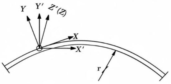
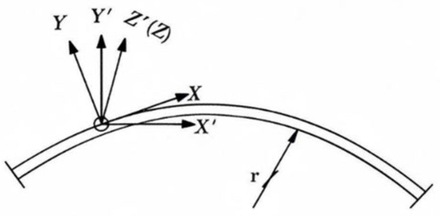
As shown in Figure 2, during finite element analysis of arch dams, stress values are obtained in the global coordinate system (x′, y′, z′). In this calculation method, a local coordinate system (x, y, z) needs to be constructed at the intersection of the horizontal arch centerline and the corresponding cantilever section:
where , , and represent the direction cosines of the x, y, and z axes, respectively. By defining the z and z′ axes as coaxial, the rotation angle from x′ to x is denoted as α (with counter-clockwise rotation defined as positive). Let the stress vector in the global coordinate system be , , , , , , and the stress vector in the local coordinate system be , , , , , . The transformation is calculated as follows:
Figure 2.
Schematic Diagram of Coordinate System Transformation.
Taking unit width at the arch axis position for the horizontal section of the cantilever, the width at point i is 1 + y/r (where r is the axis radius). Integrating the stress and moment along the thickness direction of the cantilever yields the internal forces as follows:
In the above equation, represents the beam’s return force, represents the beam’s induced moment, represents the beam’s shear force, represents the beam’s torsional shear force, and represents the beam’s torsion.
For a unit-height radial cross-section of the arch ring with a width of unity, the internal forces of the arch are obtained by integrating the stresses and moments along the thickness direction as follows:
In the above equation, represents the horizontal thrust of the arch, denotes the bending moment of the arch, and represents the shear force of the arch.
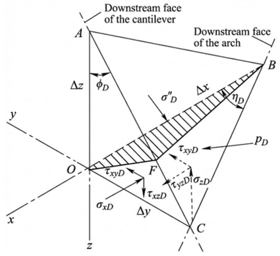
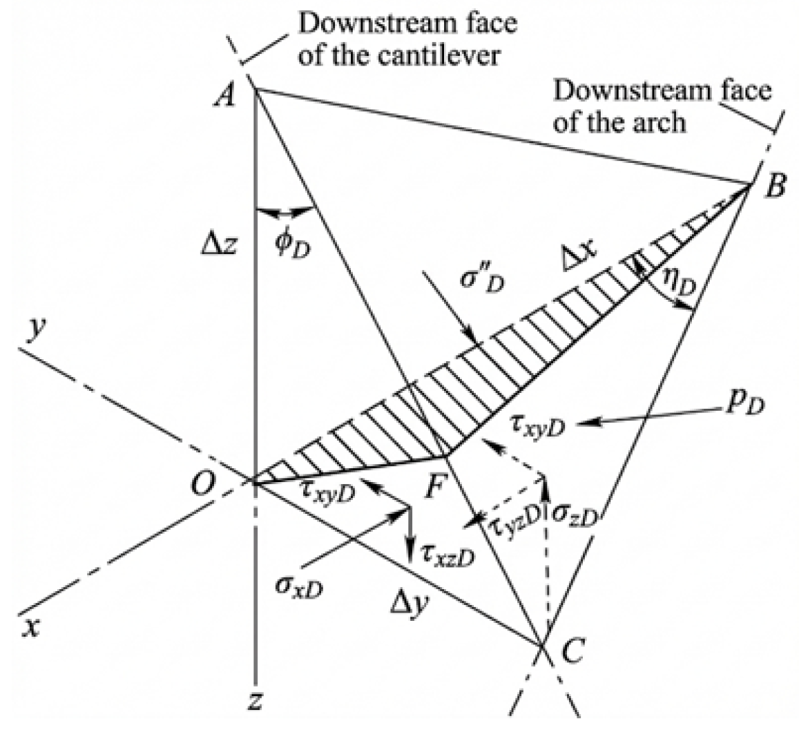
Figure 3 shows the stress diagram of the microelement on the downstream dam face. The equivalent normal stress and shear stress at the beam and arch cross-sections of this microelement are calculated as follows:
Figure 3.
Schematic diagram of stresses on a differential element of the downstream dam face.
In the equations above, denotes the angle between the downstream face of the dam and the vertical line within the radial vertical plane, and represents the angle between the downstream face and the tangent to the arch axis within the horizontal plane; the corresponding sign conventions are shown in Table 1. Additionally, is the first projected area of the differential element; is the total area of the differential element; and is the second projected area of the differential element. represents the vertical normal stress of the cantilever on the horizontal plane, while denotes the horizontal normal stress of the arch on the radial vertical plane. and correspond to the tangential horizontal shear stress of the cantilever in the x-direction on the horizontal plane (where the normal is in the z-direction) and the shear stress in the z-direction on the radial vertical plane (where the normal is in the x-direction), respectively. Furthermore, t is the section thickness of the beam; is the cross-sectional moment of inertia of the arch ring per unit height; is the distance from the centroid of the beam section to the centerline of the arch dam; and is the horizontal cross-sectional area of the beam; is the radial cross-sectional area of the arch ring per unit height, which is consistent with the section thickness t of the cantilever beam; (used in Equation (14)) is the cross-sectional moment of inertia of the cantilever beam section per unit height. The subscripts a and b correspond to the arch ring element and the cantilever beam element, respectively, to distinguish the cross-sectional characteristics of different calculation units. is the torsional moment (torque) of the cantilever beam element, corresponding to the moment generated by the section torsion effect, and serves as the controlling variable for the second term of the shear stress. is the torsional moment of inertia of the cantilever beam section, and the subscript b uniformly corresponds to the cantilever beam element.
Table 1.
Symbols of and used in the stress calculation of the dam body.
The equivalent stresses on the downstream dam face, comprising principal tensile and compressive stresses, are calculated as follows:
where , , , and are intermediate variables; denotes the downstream water pressure; represents the first principal stress; and represents the third principal stress.
2.2. Implementation of Equivalent Stress over the Whole Dam Face
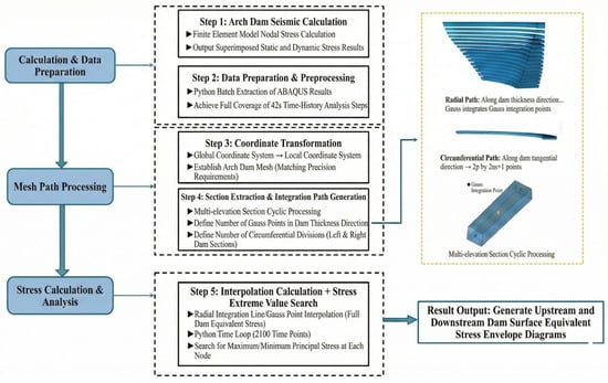
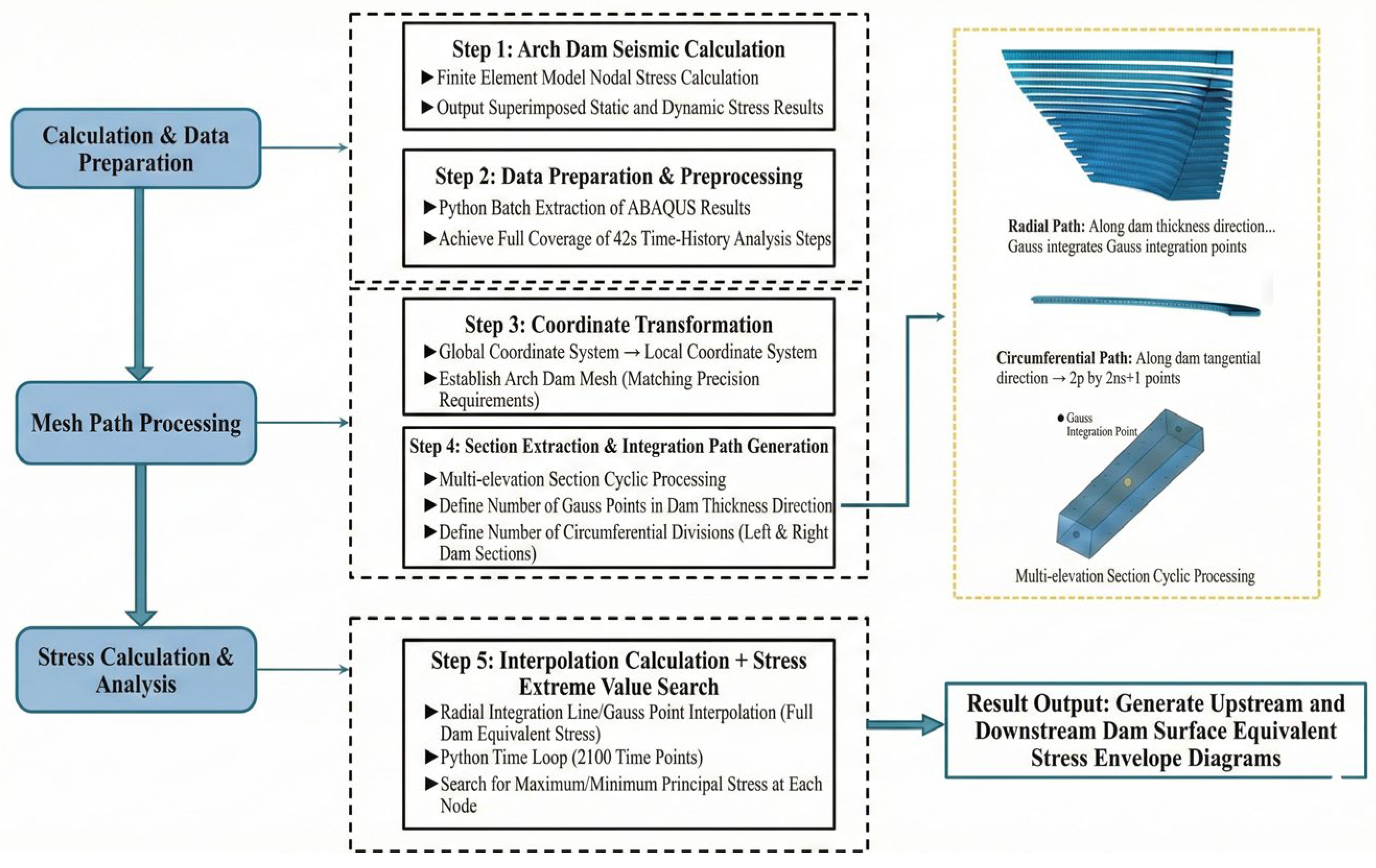
Equivalent stress over the whole dam face refers to the collection of equivalent stress values corresponding to each calculation point distributed over the entire exposed surface of an arch dam, which together constitute a global stress distribution field covering the whole dam surface. Figure 4 illustrates the specific workflow for implementing the equivalent stress over the whole dam face using ABAQUS 2025 combined with Python 3.9.7.
Figure 4.
Detailed implementation procedure.
Step 1: A three-dimensional finite element model of the arch dam is established, and stress calculations are performed at all nodes of the model, yielding the finite element stress results for each node of the dam body.
Step 2: Python scripts are employed to batch-extract the ABAQUS calculation results, covering the entire 42 s seismic time history and a total of 2100 analysis steps, thereby ensuring continuous sampling in the time domain. The extracted data include the six stress components (S11, S22, S33, S12, S13, and S23) of all nodes on the dam surface, together with their spatial coordinates and node identification numbers, ensuring the completeness of both spatial representation and stress states.
Step 3: The global coordinate system is transformed into a local coordinate system, and an arch–beam mesh consistent with the required computational accuracy is constructed.
Step 4: Multiple elevation sections are processed in a cyclic manner, with a single-section loop at each elevation. The number of Gaussian integration points along the dam thickness direction and the number of circumferential subdivisions along the left and right dam segments are defined, and the corresponding Gaussian points are calculated. Based on these parameters, a path grid is constructed.
Radial paths: along the thickness direction of the arch ring (upstream → downstream), with each path containing Gaussian integration points ().
Circumferential paths: along the tangential direction of the arch ring (left abutment → arch crown → right abutment), divided into points ( = 10, resulting in 21 circumferential points).
Grid structure: for each elevation, the arch ring forms an matrix of integration points, with each point defined by its circumferential angle and radial parameter.
Step 5: Based on Python-driven secondary development of ABAQUS, the finite element results obtained in Step 1 are interpolated along the radial integration lines and Gaussian points generated in Step 4 to compute the equivalent stress over the full dam surface. In addition, a time-history loop is independently performed for each node, and the maximum and minimum principal stresses are accurately identified from the corresponding stress histories spanning 2100 time points.
Step 6: The equivalent principal stress distributions on the upstream and downstream dam surfaces are visualized in the form of contour plots.
3. Case Study
3.1. Project Profile
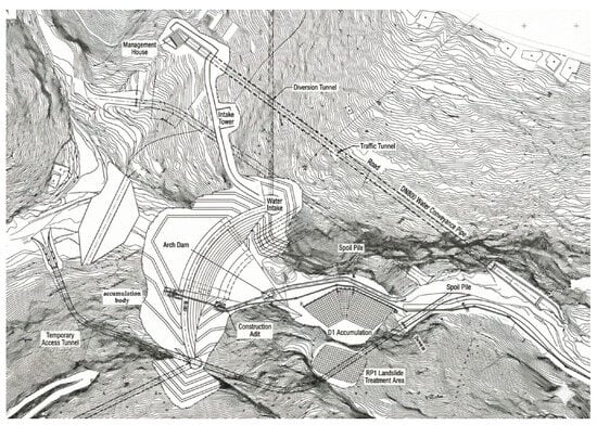
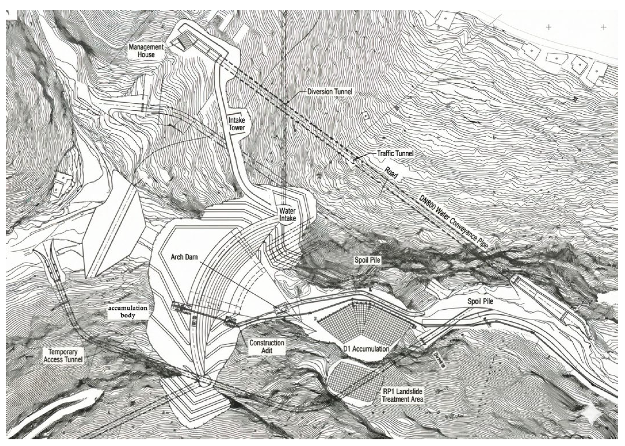
Situated in Southwest China, the project involves a concrete single-curvature arch dam with a maximum height of 88 m. The dam is characterized by a crest elevation of 1040 m, a minimum foundation elevation of 952 m, and a normal pool level of 1035 m. As illustrated in Figure 5, the reservoir project has been under construction since June 2021. Following the completion of the arch dam, the reservoir is impounded, lifted, and operated in three distinct phases: the first phase is the initial impoundment stage, primarily involving the commissioning of the dam body, spillway, and intake facilities to gradually raise the water level to the dead water level of 1006.00 m while prioritizing the monitoring of dam seepage, deformation, and foundation stability; the second phase is the water level lifting stage, during which the water level is incrementally raised from the dead water level to near the normal pool level of 1035.00 m based on downstream water supply and irrigation demands, with potential minor fluctuations resulting from pipeline system debugging and ecological release requirements; and the third phase is the normal operation stage, where the water level is stably maintained at approximately 1035.00 m, with regular scheduling adjustments performed only in response to basin inflow conditions, peak irrigation periods, and ecological replenishment needs.
Figure 5.
Arch dam project.
3.2. Three-Dimensional Finite Element Model
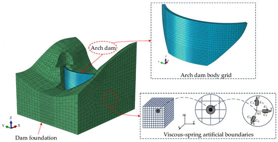
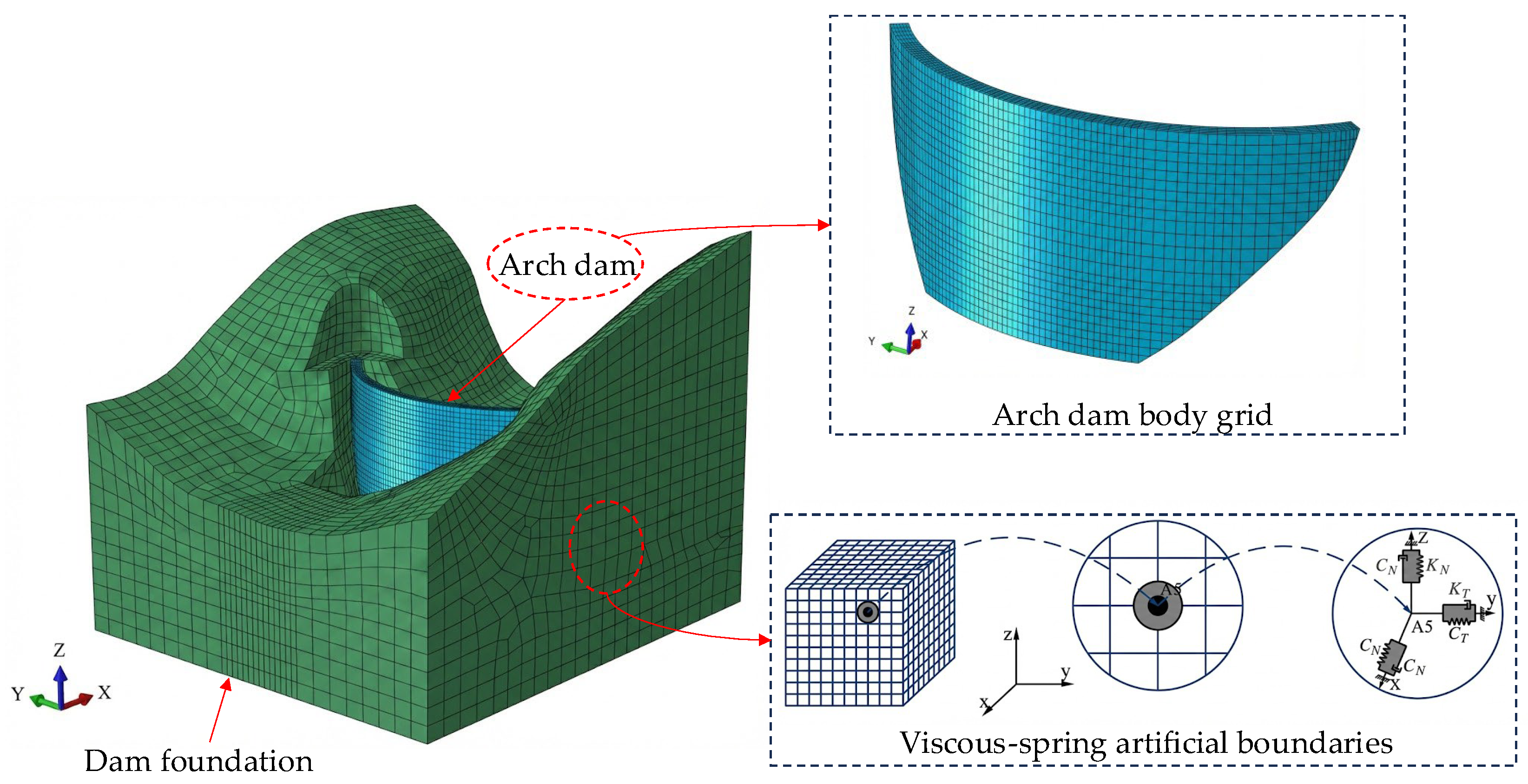
Figure 6 illustrates the finite element model of the arch dam–foundation system used for the calculation. Taking the center point of the dam base as the reference, the model domain extends 200 m (approximately twice the dam height) toward both the left and right banks and 200 m toward both the upstream and downstream directions. Vertically, the model extends 98 m (approximately once the dam height) downward, and the bottom elevation of the 3D model is set at 850 m. The complete calculation model consists of 480,866 elements and 181,886 nodes. Specifically, hexahedral C3D8 elements are employed for the dam body, while tetrahedral C3D10 elements are utilized for specific portions of the foundation.
Figure 6.
Finite element model of the arch dam–foundation system.
Table 2 lists the material properties of the arch dam system. The dam body is composed of C45 three-graded roller-compacted concrete, with basic physical and mechanical parameters including an elastic modulus of 33.5 GPa, a Poisson’s ratio of 0.21, and a density of 2420 kg/m3. The foundation rock primarily consists of weakly weathered limestone, for which the elastic modulus and Poisson’s ratio are set at 10 GPa and 0.25, respectively.
Table 2.
Material properties of the arch dam system.
In this study, the seismic response of the arch dam is simulated using a seismic wave input method based on the viscous-elastic artificial boundary [43,44,45]. Figure 6 illustrates the schematic of the viscous-elastic artificial boundary. As a technique for simulating the dynamic interaction between an infinite foundation and the structure, the core function of the viscous-elastic artificial boundary is to eliminate the artificial wave reflection phenomenon induced by the truncation of the computational domain, thereby accurately characterizing the stiffness and energy radiation damping effects of the semi-infinite foundation. This technique is implemented by arranging a parallel system consisting of viscous dampers and linear springs at the truncated boundaries of the calculation domain to effectively absorb the energy of outgoing waves.
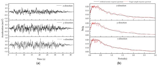
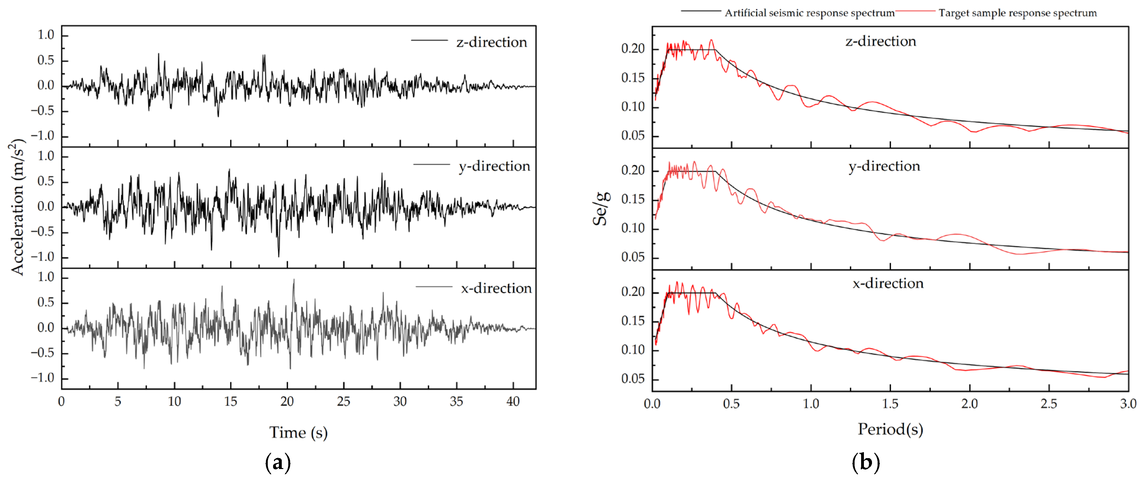
The primary loads considered in the numerical simulation of the arch dam include the dam self-weight, hydrostatic pressure, hydrodynamic pressure, silt pressure, uplift pressure, temperature, and seismic action. The calculation case adopts the normal pool level condition, with the upstream water level elevation at 1035 m, the downstream water level elevation at 970 m, and the silt elevation at 1002 m. Figure 7 presents the input three-dimensional seismic waveforms. The design intensity for this project is VII, with a corresponding peak ground acceleration of 0.1 g, a characteristic period of the response spectrum of 0.4 s, and a duration of 42 s. The seismic waves in this study are artificially generated according to the site response spectrum, where the amplitudes in the three directions are 100%X, 100%Y, and 66.7%Z, respectively. The time-discrete step is set to 0.02 s, resulting in a total of 2100 analysis time steps.
Figure 7.
Three-dimensional seismic waveforms: (a) Acceleration time histories; (b) Acceleration response spectra.
4. Results
4.1. Equivalent Stress Along the Foundation Surface
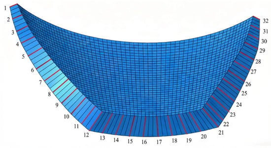
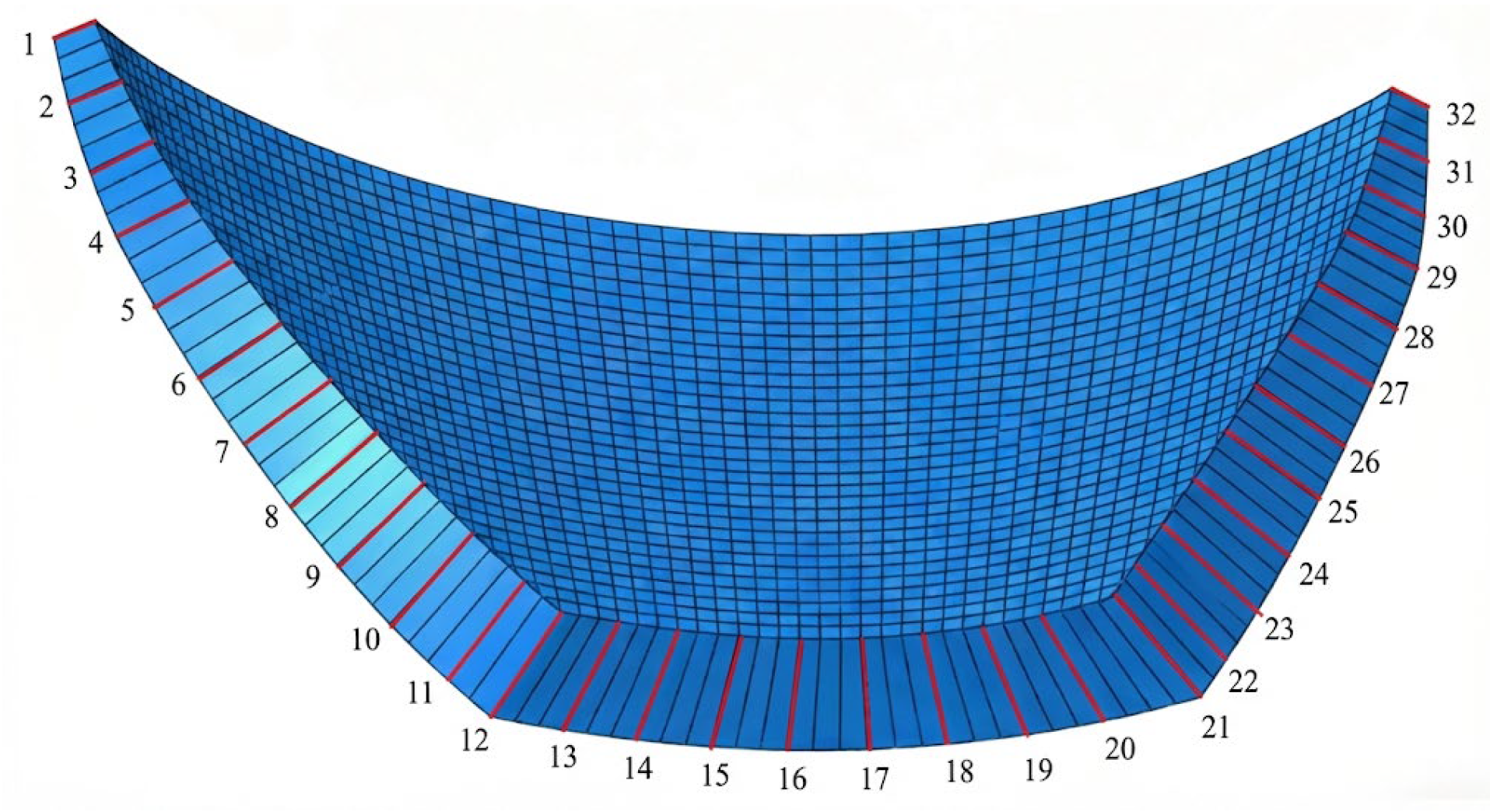
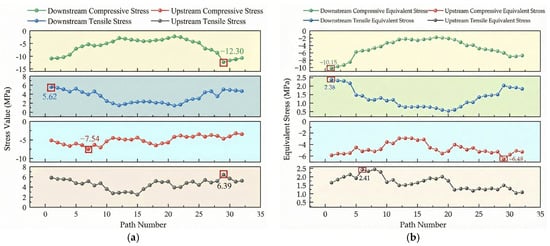
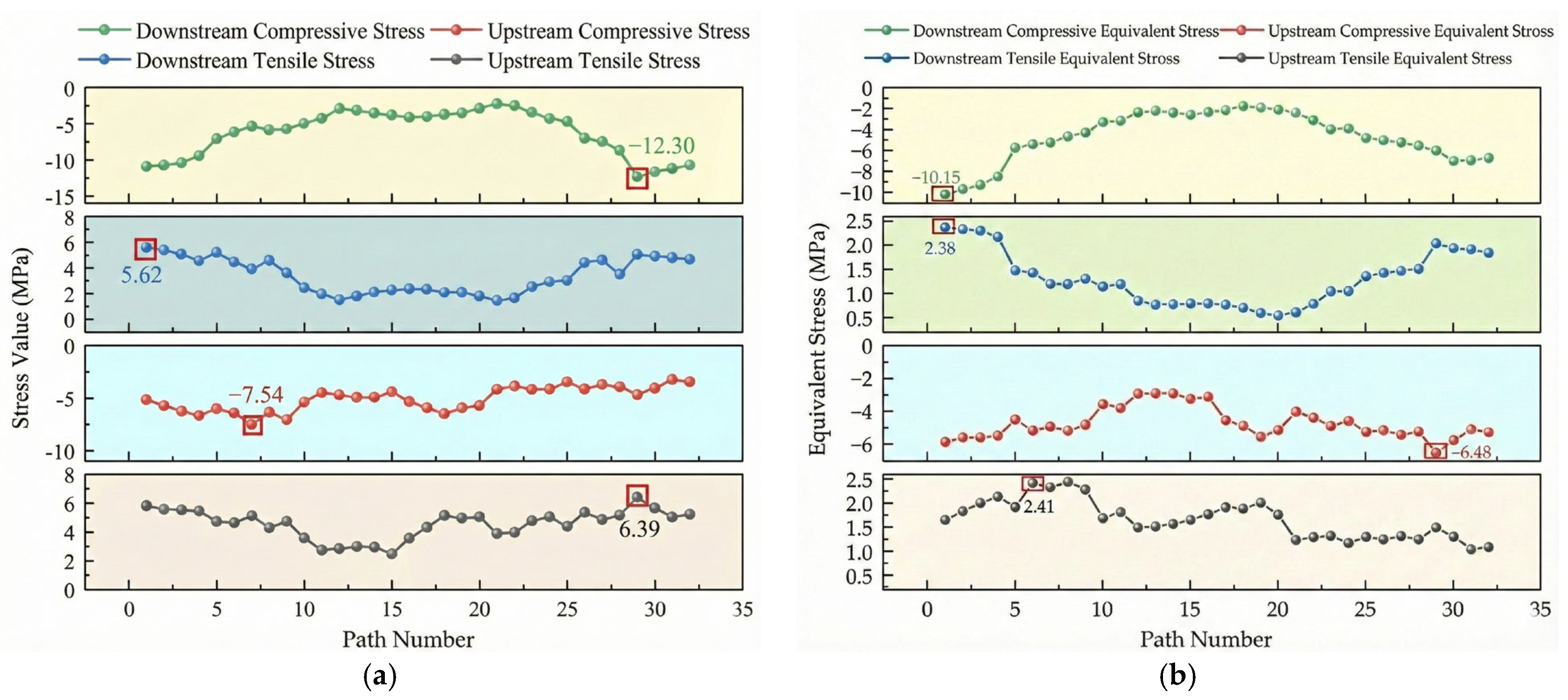
In arch dam engineering design, it is common practice to calculate equivalent stress along the foundation surface path [46,47]. Figure 8 illustrates the foundation surface path, along which 32 stress extraction lines are arranged. Following the finite element analysis of the arch dam performed using ABAQUS, the stress components of each node are extracted. Based on the calculation formulas for stress and equivalent stress, the stresses and equivalent stresses at the nodes on both the upstream and downstream faces corresponding to each extraction line are determined. Figure 9a,b present the stress envelope diagram and the equivalent stress envelope diagram along the foundation surface path, respectively. A comparison reveals that prior to equivalent processing, the stress distribution along the foundation surface path exhibits distinct non-uniform characteristics. The downstream face is primarily dominated by compressive stress, with a maximum compressive stress of approximately 12.30 MPa appearing on the foundation surface near the right-bank dam crest. Tensile stress concentration is observed at the foundation surface of the left-bank dam crest, reaching a maximum of about 5.62 MPa. On the upstream face, the tensile stress reaches the global maximum of 6.39 MPa, while the compressive stress is also prominent, with a maximum of approximately 7.54 MPa. After equivalent processing, the stress distribution along the foundation surface path becomes significantly smoother; the maximum equivalent compressive stress on the downstream face decreases to approximately 10.15 MPa, and the maximum equivalent tensile stress is controlled within 2.38 MPa. On the upstream face, the maximum equivalent compressive and tensile stresses are approximately 6.48 MPa and 2.41 MPa, respectively. Overall, the peak equivalent stresses are lower, the stress concentration is mitigated, and the stress distribution across the upstream and downstream sides of the foundation surface is more uniform and reasonable.
Figure 8.
Schematic of the foundation surface path.
Figure 9.
Comparison of stress and equivalent stress distributions along the foundation surface path: (a) Stress envelope diagram; (b) Equivalent stress envelope diagram.
4.2. Equivalent Stress over the Whole Dam Face
Under seismic action, the dam body exhibits a multi-mode coupled response. Non-foundation areas such as the dam crest, arch shoulders, and construction joints are highly susceptible to stress concentration induced by the whipping effect and sudden stiffness mutations, while high-stress zones undergo dynamic migration over the time history [48,49]. Analysis restricted to the foundation surface path alone makes it difficult to identify these globally dispersed dynamically sensitive regions, potentially overlooking the risks of tensile cracking or compressive crushing. Adopting the equivalent stress over the whole dam face avoids the spatial coverage limitations associated with analyzing only the foundation surface path, comprehensively reflecting the spatial distribution and evolutionary characteristics of the three-dimensional stress field, and enabling more accurate capturing of stress concentration areas under seismic action.
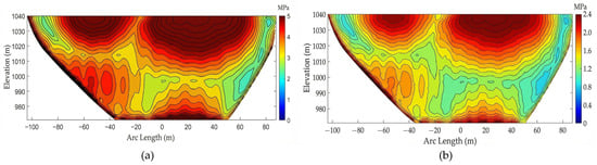
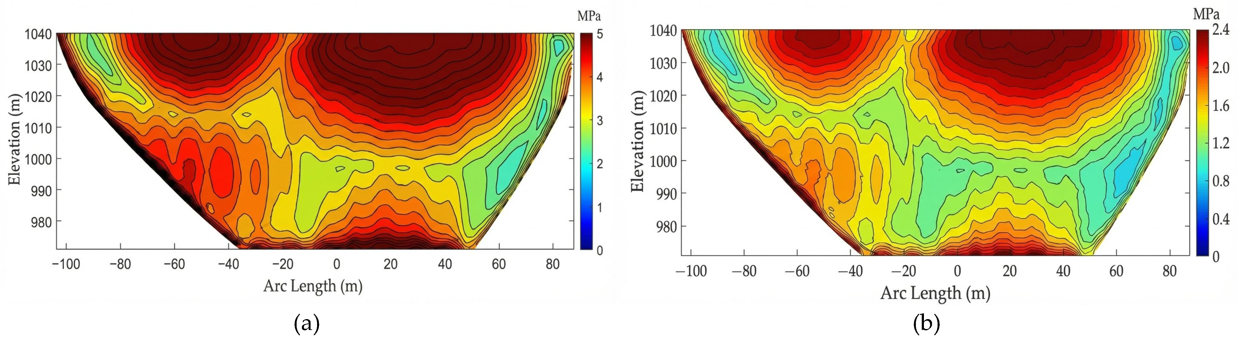
Figure 10a,b illustrate the tensile stress envelope maps of the upstream face before and after equivalence, respectively. The geometric configurations of the stress contours in both figures maintain a high degree of consistency across the entire field; notably, the spatial localization of high-stress zones—concentrated on both sides of the crown arch—coincides perfectly. This indicates that the algorithm effectively avoids the “smoothing” of physically critical local maxima and precisely identifies the key regions for crack initiation control.
Figure 10.
Envelope Diagram of Equivalent Fore-and-Aft Tensile Stress on the Upstream Face of the Dam: (a) Envelope Diagram of Equivalent Front Tensile Stress; (b) Envelope Diagram of Equivalent Rear Tensile Stress.
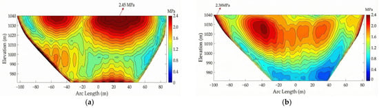
Figure 11a,b present the envelope diagrams of the equivalent tensile stress on the upstream and downstream faces, respectively. Under seismic action, a distinct stress concentration is observed on the upstream face near the left foundation area and the dam base. Moreover, two prominent regions of local stress concentration appear at the dam crest away from the foundation surface, both situated within the elevation range of 1020–1040 m, with a global maximum stress of 2.45 MPa at the dam crest. Along the vertical direction of the upstream face, the stress contours rapidly become sparse as high-stress zones extend toward higher or lower elevations. In the horizontal direction, high-stress regions are distributed in continuous sheets with tightly contracted contours.
Figure 11.
Envelope diagram of equivalent tensile stress over the whole dam face: (a) Upstream face; (b) Downstream face.
Significant stress concentration also occurs on the downstream face at the dam abutments near both sides of the foundation, with multiple localized stress concentrations appearing in the middle and upper regions away from the foundation surface. The maximum stress value is found at the left abutment near the foundation surface, reaching 2.38 MPa. Along the vertical direction of the downstream face, the contours in high-stress zones are relatively smooth, and the stress attenuation rate is slower compared to the upstream face. In the horizontal direction, high-stress areas exhibit a fragmented and clustered morphology, where contours contract rapidly within each concentration zone and show a wider divergence toward the surrounding regions.
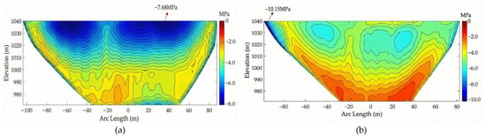
Figure 12a,b illustrate the envelope diagrams of the equivalent compressive stress on the upstream and downstream faces, respectively. Under seismic action, compressive stress concentration is observed on the upstream face within the 1020–1040 m elevation range at the dam crest, the left foundation surface, and near the dam base. Specifically, the dam crest forms the primary concentration zone due to the superposition of seismic inertial forces and the free-end effect, with the maximum compressive stress reaching 7.68 MPa. Along the vertical direction, the compressive stress attenuates rapidly from the dam crest toward higher and lower elevations, and the contours become significantly sparser. In the arc length direction, high-stress regions are distributed in continuous blocks with tightly contracted contours, indicating that under the combined action of seismic loads and hydrostatic pressure, the upstream face exhibits favorable stress continuity in the horizontal direction without significant localized stress concentration.
Figure 12.
Envelope diagram of equivalent compressive stress over the whole dam face: (a) Upstream face; (b) Downstream face.
On the downstream face, compressive stress concentrations are primarily observed at the left dam crest, along the foundation surfaces of both abutments, and within localized regions of the middle and upper dam body. The concentration at the left foundation surface of the dam crest is the most significant, with the maximum equivalent compressive stress reaching 10.15 MPa. Along the vertical direction, the contours in the high-stress zones are relatively smooth, and the stress attenuation rate is slower compared to that of the upstream face. In the horizontal direction, the contours contract rapidly within each concentration zone while extending across a wider range, reflecting intense but dispersed compressive stress variations characterized by multi-point localized stress concentrations.
Table 3 presents the distribution of peak equivalent stress over the whole dam face. Equivalent stress analysis along the foundation surface path is constrained by the preset paths, making it difficult to comprehensively reflect the stress characteristics in critical regions such as the dam crest and the middle of the dam face. In contrast, equivalent stress calculation over the whole dam face not only accurately captures the tensile and compressive stress peaks at the foundation surface but also effectively identifies stress concentration areas within the middle of the dam crest and across the dam body. This approach achieves a global characterization of the dam stress field under seismic action, intuitively and systematically revealing the laws of spatial stress distribution and providing a reliable quantitative basis for the holistic evaluation of arch dams under seismic action.
Table 3.
Summary of peak equivalent stress distribution over the whole dam face.
4.3. Verification of Computational Consistency
To verify the numerical reliability and the algorithmic consistency of the equivalent stress over the whole dam face calculated via ABAQUS integrated with Python-based secondary development, this study performs a comparative analysis between the numerical results of the full-surface equivalent tensile stress on the upstream face and those obtained via the traditional integration method along the foundation surface path. Table 4 presents the comparative data for the upstream equivalent tensile stress calculated by both methods. A detailed comparison of the results at the corresponding nodes along the seven stress extraction lines reveals an excellent agreement between the distributions of the full-surface equivalent stress and the foundation-path equivalent stress, with a maximum relative error of only 1.62%. This result confirms that the proposed full-surface method is numerically highly consistent with the traditional path-based method, demonstrating that the methodology accurately reproduces the stress equivalence process without introducing additional computational bias.
Table 4.
Verification of calculation consistency of equivalent tensile stress on the entire dam surface.
5. Discussion
Existing research on arch dam equivalent stress analysis has established a mature theoretical framework for foundation-surface path calculations, which has been widely adopted in engineering design [18]. However, most existing studies remain confined to solving equivalent stresses along discrete preset paths at the dam-foundation interface, leaving a research gap in the global characterization of the equivalent stress field across the entire dam face under seismic action. The core breakthrough of this study lies in extending the computational scope of equivalent stress from localized foundation paths to 100% coverage of the entire upstream and downstream exposed surfaces, alongside the establishment of an automated calculation framework for whole-dam-face equivalent stress tailored for seismic time-history analysis. Compared to the traditional standard methods specified in engineering codes, the maximum relative error of the proposed methodology is only 1.62%, which is well below the 5% allowable error limit for water conservancy engineering. While significantly expanding the analytical range, this method ensures the reliability of the numerical results and addresses a long-standing research gap in the field.
For the 88 m-high medium-to-low arch dam investigated in this study, the spatial distribution patterns of equivalent stress under seismic action and the identified high-risk zones exhibit inherent stability. Established research and engineering practices in the seismic analysis of arch dams demonstrate that, provided the spectral characteristics of the seismic waves match the site’s design response spectrum, variations in phase structure, duration, and the substitution of artificial waves with recorded accelerograms of similar spectral properties only influence the numerical magnitude of stress extrema. Such variations do not alter the overall spatial distribution of the stress field or the localization of core high-risk zones. The whiplash effect at the dam crest and the stress concentration along the foundation surface of the abutments are inherent dynamic response characteristics of arch dams under seismic excitation, remaining largely independent of the specific time-domain characteristics of the seismic waves. Regarding variations in seismic intensity levels, provided that the dam concrete remains entirely within the linear elastic working stage, changes in intensity only produce a linear scaling effect on the stress extrema and do not alter the spatial distribution patterns of the whole-dam-face equivalent stress field. The core high-risk zones identified in this study—namely the central dam crest and the foundation surface along the left dam crest—remain the primary stress-control regions across various seismic intensity levels.
The uniqueness and scientific innovation of this study are primarily manifested in three aspects: first, theoretical innovation, which establishes a systematic theoretical framework for calculating the equivalent stress over the whole dam face under seismic action, thereby achieving a theoretical expansion from localized path-based solutions to global stress-field characterization; second, methodological innovation, through the proposal of an automated calculation framework based on Python-based secondary development that significantly enhances computational efficiency compared to traditional manual methods; and third, applied innovation, which transcends the spatial coverage limitations of traditional approaches to effectively identify stress concentration zones in non-foundation regions often overlooked by conventional methods, while directly aligning with the technical requirements of modern intelligent monitoring and digital twin management in hydraulic engineering. The primary advantages of this methodology include reliable numerical accuracy that fully satisfies engineering code requirements, the achievement of comprehensive spatial coverage across the entire dam face, high computational efficiency, excellent compatibility with existing engineering design workflows, and robust dynamic adaptability for seismic time-history analysis.
At the same time, certain limitations, inherent deficiencies, and potential application risks remain in the proposed methodology. Regarding its application constraints, the method is established within a linear elastic finite element computational framework and is strictly applicable to scenarios where the dam concrete operates entirely within the linear elastic stage. Given that this study employs an 88 m-high medium-to-low single-curvature arch dam as the verification case, targeted parameter calibration would be necessary when applying the method to ultra-high or double-curvature arch dams. Furthermore, this research focuses exclusively on design seismic conditions, omitting the coupling effects of long-term performance deterioration factors such as concrete creep and freeze–thaw cycles.
6. Conclusions
In this study, the secondary development of ABAQUS with Python was utilized to successfully implement stress extraction along multiple arch ring integration paths and the calculation of equivalent stress over the whole dam face. The following conclusions are drawn:
- Reliability of the Technical Framework: Comparative analysis reveals that the results of the full-surface equivalent stress show high consistency with those along the traditional foundation surface path. The maximum relative error is only 1.62%, indicating that the computational consistency of the proposed method satisfies the criteria for numerical verification in engineering applications.
- Superiority of Global Characterization: While equivalent stress analysis along the foundation surface path can capture local stress concentrations at the dam base, it is inherently limited by preset paths and struggles to identify dynamically sensitive regions in non-path areas. In contrast, the full-surface method achieves a global characterization of the three-dimensional stress field, more effectively identifying critical peak stress regions at the dam crest and middle sections that might otherwise be overlooked.
- Seismic Response and Stress Concentration Patterns:
- (1)
- Under seismic excitation, the dam crest exhibits significant stress concentration due to the superimposed influence of the whipping effect and free-end effects.
- (2)
- The global maximum equivalent tensile stress (2.45 MPa) and equivalent compressive stress (7.68 MPa) for the upstream face both occur at the middle of the dam crest.
- (3)
- The most prominent stress concentration on the downstream face is located at the foundation surface near the dam crest on the left bank, with a maximum equivalent compressive stress of 10.15 MPa.
- Engineering Significance and Scope of Application: The proposed methodology overcomes the spatial coverage limitations inherent in traditional local path-based analysis, providing an intuitive and systematic elucidation of the spatial stress distribution patterns in arch dams. Consequently, it offers a robust quantitative basis for the global safety assessment, design optimization, and seismic reinforcement of arch dams situated in high-intensity seismic regions. In terms of scientific research, this work lays a preliminary foundation for the subsequent study on the full-field equivalent stress evolution of arch dams under complex multi-factor coupling conditions. In engineering practice, this method can also be adapted to the existing arch dam design workflow, providing a supplementary technical means for the comprehensive stress screening of dam structures. While highly effective for crack resistance safety assessments and comprehensive stress-field screenings during the routine design phase, this method is not intended for the refined nonlinear analysis of macro-damage evolution or the determination of ultimate bearing capacity under strong seismic excitations.
Author Contributions
H.P. was involved in conceptualization, methodology, funding acquisition, and writing—original draft; M.W. was involved in data curation, software, validation, formal analysis, and writing—original draft; L.J. was involved in writing—review and editing; B.Z. was involved in writing—review and editing. All authors have read and agreed to the published version of the manuscript.
Funding
This study was supported by the National Key Research and Development Program of China (Grant No. 2021YFC3001901-02) and the Hubei Provincial Innovative Research Team Program for Outstanding Young and Middle-aged Talents in Universities (Grant No. T2022007).
Institutional Review Board Statement
Not applicable.
Informed Consent Statement
Not applicable.
Data Availability Statement
The original contributions presented in this study are included in the article. Further inquiries can be directed to the corresponding author.
Conflicts of Interest
The authors declare no conflict of interest.
References
- Li, H.K.; Tang, Y.Y.; Liu, B.; Wang, G. Research progress on finite element model updating of hydraulic structures based on vibration response. Adv. Sci. Technol. Water Resour. 2025, 45, 70–80. [Google Scholar]
- John, R.; Balakrishnan, S.D. Investigations on seismic response of Idukki Arch Dam considering concrete ageing. Innov. Infrastruct. Solut. 2025, 10, 404. [Google Scholar] [CrossRef] [Scilit]
- Yan, J.Y.; Wang, F.; Li, Y.H.; Ma, C.; Zhou, J.; Yu, H. Prediction and analysis of temperature recovery after arch closure grouting of Baihetan Arch Dam. Adv. Eng. Softw. 2025, 210, 104012. [Google Scholar] [CrossRef] [Scilit]
- Fu, C.H.; Zhou, H.B.; Pan, Y.F. Calculation and improvement of complex mechanical properties of the mega arch dam under multiple loads based on finite element methods. Complexity 2018, 2018, 2582561. [Google Scholar] [CrossRef] [Scilit]
- Shao, C.F.; Xu, Y.X.; Chen, J.; Zheng, S.; Gu, H.; Qin, X.N. Numerical analysis method of equivalent deformation parameters for grouted arch dam abutment fractured rock masses considering scale effects and anisotropy. Comput. Geotech. 2024, 165, 105929. [Google Scholar] [CrossRef] [Scilit]
- Conde, A.; Salete, E.; Toledo, M.Á. Detection of cracks in arch dams using monitoring data and numerical models. Appl. Sci. 2025, 15, 6105. [Google Scholar] [CrossRef] [Scilit]
- Wang, Y.Q.; Zhao, R.H.; Liu, Y.; Chen, Y.Z.; Ma, X.Y. Shape optimization of single-curvature arch dam based on sequential kriging-genetic algorithm. Appl. Sci. 2019, 9, 4366. [Google Scholar] [CrossRef] [Scilit]
- Xu, B.; Lu, J.Y.; Wang, S.W.; Chen, X.D.; Qin, X.N.; Bu, J.W.; Qiu, J.C.; Sun, L.S.; Li, Y.T. A novel optimal sensor placement framework for concrete arch dams based on IAHA considering the effects of cracks and elastic modulus degradation. Appl. Sci. 2024, 14, 8921. [Google Scholar] [CrossRef] [Scilit]
- Jiang, J.F.; Zhao, Q.H.; Deng, Y.H.; Wang, Y.; Wu, H. Characteristics of deep fractured rock mass at Yebatan Dam site and its influence on arch dam stability. Yangtze River 2024, 55, 157–167. [Google Scholar]
- Ingle, S.; Lin, L.; Li, S.S. Seismic Assessment of Concrete Gravity Dam via Finite Element Modelling. GeoHazards 2025, 6, 53. [Google Scholar] [CrossRef] [Scilit]
- Wang, R.K.; Lin, P.; Zhou, W.Y. Research on cracking and stability of high arch dams on complex foundations. Chin. J. Rock Mech. Eng. 2007, 26, 1951–1958. [Google Scholar]
- Fu, Z.X.; Qian, X.D. Application of finite element method in arch dam design. J. Hohai Univ. 1991, 19, 8–15. [Google Scholar]
- Li, H.F.; Li, B.Q.; Yang, B. A comparative study of the cracking effect of induced joints of various spatial formations. Math. Probl. Eng. 2019, 2019, 7876503. [Google Scholar] [CrossRef] [Scilit]
- Zhang, L.; Mao, J.; Zhao, L.H. Nonlinear seismic assessment of concrete dams using a novel elastoplastic damage numerical framework. J. Eng. Mech. 2025, 151, 04025004. [Google Scholar] [CrossRef] [Scilit]
- Zhang, X.F.; Yan, T.; Liu, Q.; Zhang, X.; Wang, L. Cracking analysis of induced joints in roller compacted concrete arch dam. Alex. Eng. J. 2022, 61, 3599–3612. [Google Scholar] [CrossRef] [Scilit]
- Cai, Q.; Yang, M.F.; Yang, J.G. Study on the freeze–thaw effect on concrete arch dam using an improved response surface method. Sci. Rep. 2023, 13, 19175. [Google Scholar] [CrossRef] [Scilit]
- Wang, M.; Wu, Y.X. 3D finite element equivalent stress analysis of roller compacted concrete arch dam. Low Temp. Archit. Technol. 2014, 36, 99–102. [Google Scholar]
- Cheng, H.Y.; Xiang, X.; Cheng Wen, B.H.; Jiang, Y.; Zhang, J.X. 3D finite element equivalent stress calculation of arch dam based on ABAQUS. Pearl River 2023, 44, 105–111. [Google Scholar]
- Zhou, J.P.; Du, X.K.; Zhang, L.B. Comparative study on measured and calculated stresses at dam heel of high arch dams. J. Hydroelectr. Eng. 2017, 36, 87–94. [Google Scholar]
- Liu, Y.; Wang, H.; Yan, L.; Yu, J.; Zeng, W.; Xu, W. Study on Valley Shrink Deformation of the High Arch Dam with Large Faults near Dam Area during Initial Impoundment. Water 2024, 16, 2694. [Google Scholar] [CrossRef] [Scilit]
- Zhang, Z.Z.; Zhang, C.; Li, L.; Liu, X.H.; Chang, X.L. Simulation analysis and evaluation of stress of Dagangshan Arch Dam in empty reservoir condition during construction period. J. Wuhan Univ. 2015, 48, 459–465. [Google Scholar]
- Angelakis, A.N.; Baba, A.; Valipour, M.; Dietrich, J.; Fallah-Mehdipour, E.; Krasilnikoff, J.; Bilgic, E.; Passchier, C.; Tzanakakis, V.A.; Kumar, R.; et al. Water Dams: From Ancient to Present Times and into the Future. Water 2024, 16, 1889. [Google Scholar] [CrossRef] [Scilit]
- Wang, R.K. Key technologies and practices in construction of 300m-class ultra-high arch dams. Engineering 2016, 2, 184–203. [Google Scholar] [CrossRef] [Scilit]
- Kong, X.J.; Chen, J.Y.; Zou, D.G. Research on the development trend of seismic safety theory for high dams. J. Hydroelectr. Eng. 2020, 39, 1–11. [Google Scholar]
- Zhai, Y.F.; Zhang, L.J.; Cui, B.H.; Bi, Z.H.; Zhang, H.Y. Research on global damage and failure of gravity dams under pulse-type seismic action. J. Hydroelectr. Eng. 2021, 40, 132–140. [Google Scholar]
- Chen, S.H.; Wang, G.J.; Zhou, H.; Wang, W.M.; Zou, L.C. Evaluation of excavation-induced relaxation and its application to an arch dam foundation. Int. J. Numer. Anal. Meth. Geomech. 2012, 36, 166–181. [Google Scholar] [CrossRef] [Scilit]
- Zhang, C.H.; Xu, Y.J.; Wang, G.L.; Jin, F. Non-linear seismic response of arch dams with contraction joint opening and joint reinforcements. Earthq. Eng. Struct. Dyn. 2000, 29, 1547–1566. [Google Scholar] [CrossRef] [Scilit]
- Saouma, V.; Perotti, L. Constitutive model for alkali-aggregate reactions. ACI Mater. J. 2006, 103, 194–202. [Google Scholar] [CrossRef] [Scilit]
- Lin, P.; Wei, P.; Wang, W.; Huang, H. Cracking Risk and Overall Stability Analysis of Xulong High Arch Dam: A Case Study. Appl. Sci. 2018, 8, 2555. [Google Scholar] [CrossRef] [Scilit]
- Landar, S.; Velychkovych, A.; Ropyak, L.; Andrusyak, A. A Method for Applying the Use of a Smart 4 Controller for the Assessment of Drill String Bottom-Part Vibrations and Shock Loads. Vibration 2024, 7, 802–828. [Google Scholar] [CrossRef] [Scilit]
- Landar, S.; Velychkovych, A.; Vytvytskyi, V.; Ropyak, L. Threshold Vibration Metrics of Drilling Tools as Indicators of Bit Wear and Rate of Penetration Decline: Field Trials and Data Interpretation. Min. Miner. Depos. 2025, 19, 147–157. [Google Scholar] [CrossRef] [Scilit]
- Bado, M.F.; Casas, J.R. A Review of Recent Distributed Optical Fiber Sensors Applications for Civil Engineering Structural Health Monitoring. Sensors 2021, 21, 1818. [Google Scholar] [CrossRef] [Scilit] [PubMed]
- Bojea, C.; Guerriero, A.; Kubickia, S.; Rezgui, Y. Towards a Semantic Construction Digital Twin: Directions for Future Research. Autom. Constr. 2020, 114, 103179. [Google Scholar] [CrossRef] [Scilit]
- Li, Y.F.; Wang, J.; Shan, Y.G.; Wang, C.; Hu, Y.B. Measurement and Analysis of Downhole Drill String Vibration Signal. Appl. Sci. 2021, 11, 11484. [Google Scholar] [CrossRef] [Scilit]
- Tian, J.C.; Chen, C.; Zhang, L.M.; Chen, J.K.; Huang, H.B.; Zhang, P.T. A Digital Twin Method for Real-Time Analysis of Structural Deformation and Failure for High Arch Dams. Eng. Struct. 2025, 345, 121426. [Google Scholar] [CrossRef] [Scilit]
- Shao, C.F.; Zheng, S.; Xu, Y.X.; Gu, H.; Qin, X.N.; Hu, Y.T. A Visualization System for Dam Safety Monitoring with Application of Digital Twin Platform. Expert Syst. Appl. 2025, 271, 126740. [Google Scholar] [CrossRef] [Scilit]
- Cheng, L.; Ma, C.H.; Yuan, X.N.; Yang, J.; Hu, L.C.; Zheng, D.J. A Literature Review and Result Interpretation of the System Identification of Arch Dams Using Seismic Monitoring Data. Water 2022, 14, 3207. [Google Scholar] [CrossRef] [Scilit]
- Xu, B.; Chen, Z.Y.; Su, H.Z.; Zhang, H. A Deep Learning Method for Predicting the Displacement of Concrete Arch Dams Considering the Effect of Cracks. Adv. Eng. Inform. 2024, 62, 102574. [Google Scholar] [CrossRef] [Scilit]
- Conde, A.; Toledo, M.Á.; Salete, E. Impact of Arch Dam Cracking on Monitoring Data. Appl. Sci. 2025, 15, 1096. [Google Scholar] [CrossRef] [Scilit]
- Sosnovskii, L.A. Determination of equivalent stress on the basis of a statistical theory of fatigue fracture in a complex stress state. Strength Mater. 1984, 16, 453–457. [Google Scholar] [CrossRef] [Scilit]
- Schmidt, A.T.; Pandiya, N. Extension of the static equivalent stress hypotheses to linearly vibrating systems using wave interference—The LiWi approach. Int. J. Fatigue 2021, 147, 106103. [Google Scholar]
- Solowski, W.T.; Sloan, S.W. Equivalent stress approach in modelling unsaturated soils. Int. J. Numer. Anal. Methods Geomech. 2012, 36, 1667–1681. [Google Scholar] [CrossRef] [Scilit]
- Li, X.Z.; Song, Y.Q.; Azzara, R.; Filippi, M.; Carrera, E. Variable-kinematic finite beam elements and viscous-spring artificial boundary for wave propagation in infinite space. J. Mech. 2025, 41, 129–136. [Google Scholar]
- Jia, Z.M.; Zhao, B.M. The influence of stratigraphic conditions in horizontally layered soils on the propagation dynamics of seismic waves. Soil Dyn. Earthq. Eng. 2025, 199, 109720. [Google Scholar] [CrossRef] [Scilit]
- Ye, D.; Yin, S.Z.; Wang, Y.H.; Zuo, T.A. An arc-consistent viscous-spring artificial boundary for numerical analysis of seismic response of underground structures. Shock Vib. 2022, 2022, 2791492. [Google Scholar]
- Wang, J.T.; Lv, D.D.; Jin, F.; Zhang, C.H. Earthquake damage analysis of arch dams considering dam–water–foundation in-teraction. Soil Dyn. Earthq. Eng. 2013, 49, 64–74. [Google Scholar] [CrossRef] [Scilit]
- Luo, D.; Lin, P.; Li, Q.B.; Zheng, D.; Liu, H.Y. Effect of the impounding process on the overall stability of a high arch dam: A case study of the Xiluodu dam, China. Arab. J. Geosci. 2015, 8, 9023–9041. [Google Scholar] [CrossRef] [Scilit]
- Ren, H.L.; Wu, Y.L.; Li, W.; Cai, X. Seismic damage assessment using frequency characteristics of acceleration records in centrifugal vibration table tests for CSG dam. Soil Dyn. Earthq. Eng. 2026, 203, 110000. [Google Scholar] [CrossRef] [Scilit]
- Pan, J.W.; Wang, J.T. Effect of abutment movements on nonlinear seismic response of an arch dam. Struct. Infrastruct. Eng. 2020, 16, 1106–1120. [Google Scholar]

Disclaimer/Publisher’s Note: The statements, opinions and data contained in all publications are solely those of the individual author(s) and contributor(s) and not of MDPI and/or the editor(s). MDPI and/or the editor(s) disclaim responsibility for any injury to people or property resulting from any ideas, methods, instructions or products referred to in the content. |
© 2026 by the authors. Licensee MDPI, Basel, Switzerland. This article is an open access article distributed under the terms and conditions of the Creative Commons Attribution (CC BY) license.