


Abstract
During the assembly process of the bolter miner cutting drum, the varying installation postures of the cutting picks result in unique and non-repetitive irregular gaps between the tooth seat bottom surface and the cylindrical rotating surface. Such gaps are constrained by dual-surface geometry and lack batch statistical regularity, making traditional methods such as shim filling, selective assembly, or on-site welding inadequate for achieving high-precision fitting and reliable process implementation. To address this challenge, this paper proposes an automatic design method for compensation bodies based on computer-aided design, realizing a shift from experience dependence to algorithm-driven design. This method transforms the complex dual-surface gap filling problem into a serialized geometric modeling process: first, smooth extrapolation of the tooth seat bottom surface is achieved through a point sequence prediction model based on minimum mean square error; second, surface projection is simplified to boundary curve projection, enabling precise mapping onto the cylindrical surface and generating trimming surfaces; finally, a ruled surface is constructed to integrate the extended surface with the trimming surfaces, automatically generating a compensation body fully adapted to the gap morphology. Case verification demonstrates that this method can automatically and accurately generate compensation bodies that meet dual-surface fitting requirements, significantly improving geometric adaptability and weldability. This research not only resolves a critical technical bottleneck in the assembly of bolter miner cutting drums but also provides a universal and scalable computational framework for the intelligent compensation design of non-repetitive dual-surface gaps in complex equipment.
1. Introduction
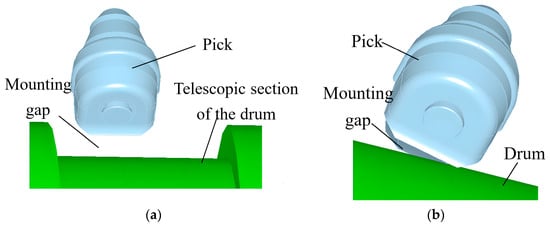
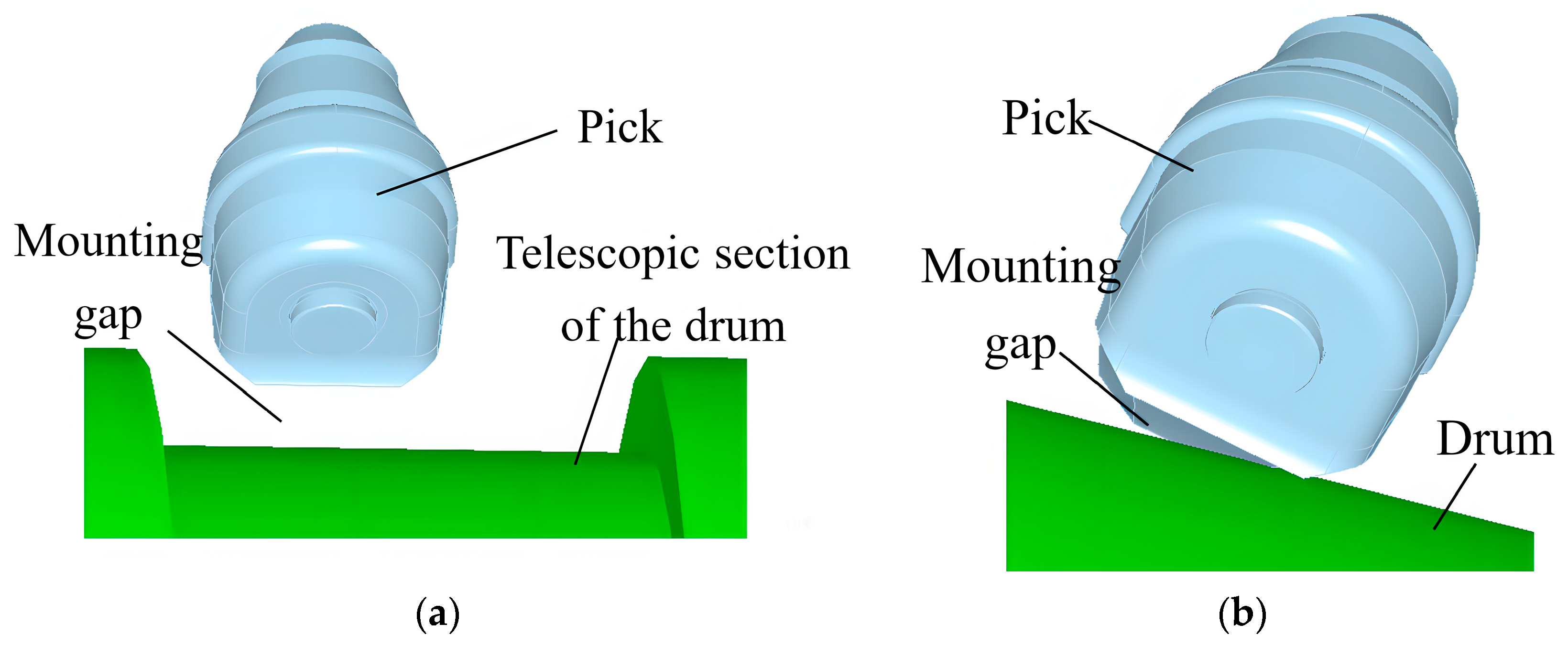
Although China is actively promoting the diversification of its energy structure, coal remains a crucial component of its domestic energy supply. Consequently, efficient and safe coal mining serves as a fundamental pillar for ensuring national energy security [1,2]. With the development of intelligent fully mechanized mining technology [3,4], there are significantly heightened demands for the performance and reliability of equipment such as the bolter miner. As the core executive component of coal breaking and coal falling, the cutting drum’s working performance directly determines the production efficiency, energy consumption level, and service life of the shearer [5,6]. The picks on the cutting drum of the bolter miner are key components; wear and fracture are their main failure forms [7]. To achieve optimal cutting performance, picks often require specific orientation adjustments and spatial arrangements tailored to working conditions. However, such necessary adjustments inevitably alter the relative position and orientation between the picks and the drum, leading to the formation of irregular assembly gaps between the pick holder base and the drum surface. As shown in Figure 1a, when a pick is located at the telescopic part of the drum, it is completely suspended. As shown in Figure 1b, when a pick is adjusted in orientation due to local layout requirements, an installation gap is generated between the pick holder and the drum body. If such gaps are filled directly by welding, the narrow weld seams can compromise welding quality and increase the risk of pick fracture [8]. Therefore, for the aforementioned scenarios, adding a compensation body becomes an essential pre-installation process step. However, the design and implementation of customized compensation bodies themselves pose a severe challenge. Currently, the design of such compensation bodies relies heavily on manual experience, involving iterative trial-and-error and manual modifications of 3D models to approximate the gap geometry. This process is not only inefficient and time-consuming but also struggles to guarantee high-precision geometric conformity with complex, irregular gaps, resulting in poor quality consistency. The fundamental difficulty lies in the fact that each gap is unique in morphology and cannot be reproduced in batches, necessitating a “one-to-one” design and manufacturing approach for each pick holder. This task faces core constraints that are difficult to overcome with traditional methods: (1) the compensation body must achieve high-precision conformity with both the complex free-form surface of the pick holder and the regular cylindrical surface of the drum, a dual-surface constraint that conventional shims cannot accommodate; (2) the installation orientation and gap morphology of each pick holder are unique, offering no statistical basis for batch production, which renders selective assembly strategies ineffective; (3) the effective contact area on the pick holder base is often limited, making traditional on-site processes like welding difficult to implement with consistent quality.
Figure 1.
Schematic diagram of pick-drum assembly gap types. (a) Pick at telescopic section. (b) Pick posture adjustment.
While assembly gaps have been extensively studied by many experts worldwide, systematic research specifically focused on the automatic generation and design of customized compensation bodies for the irregular free-form assembly gaps between the pick holders and the drum body of bolter miner cutting drums remains scarce. Research on compensation methods for assembly gaps is primarily concentrated in three main directions. The first is to improve the manufacturing accuracy of parts; the second is to fill the gap area with appropriate gaskets; the third is the selective assembly strategy [9]. Due to the limitations in cost and process, the first method has not been widely used, while the second method has been widely used in the aviation industry, especially in the bolt connection structure of aerospace composite materials. Yue studied the effect of assembly clearance and gasket on the strain and stress state of the composite aluminum assembly structure [10]. Cheng studied the influence of gaskets with different materials and parameters on bolted connections [11]. Huehne studied the effect of a liquid gasket layer added between two laminates on the strength and structural behavior of the joint through a virtual test [12]. Yang proposed that assembly gaps reduce component strength, but shim materials can compensate for this strength loss [13]. Sun proposed a clearance optimization method based on component attitude alignment to assist the intelligent assembly of aircraft composite plates [14]. The above research shows that the gasket can effectively improve the uniformity of load distribution. However, their methods are based on the assumption that the gap morphology can be approximated by standard or simple-shaped shims. For the complex free-form surface of the tooth seat bottom described in this paper, this assumption no longer holds, and therefore, their methods cannot be directly applied. Meanwhile, the third method has found extensive application in bearing manufacturing. Its core lies in first inspecting the components and then grouping them or performing optimal one-to-one matching based on the measured dimensions. This approach has successfully mitigated, in part, the inherent conflict between achieving high assembly quality and maintaining low manufacturing costs [15,16]. However, the effectiveness of these two methods is based on specific prerequisites: shim compensation requires relatively regular or predictable gap morphology to enable effective filling with standard shims, and the process quality heavily relies on operator experience [17]. Selective assembly strictly depends on the statistical regularity of dimensions from large batches of parts. Consequently, both methods exhibit limitations when applied to the assembly gap issues between the bolter miner cutting drum and pick holders. To address this, the technological approach must shift from selection and filling to computation and generation—that is, achieving parametric automatic modeling of compensation bodies through computer-aided geometric design. In fact, parametric methods such as B-splines serve as versatile tools for geometric representation and have been widely applied to complex interface and surface reconstruction problems across various fields [18,19]. For instance, in fluid dynamics, Vallisa proposed a novel interface reconstruction method based on B-spline parametric surfaces [20], which was successfully applied to simulate freely falling natural particles in thermal-buoyant flows, demonstrating its capability to handle complex and dynamic geometries. In the field of mechanical engineering, Gao proposed a surface extrapolation algorithm for reconstructing the twisted blade tip through the extreme value parameterization of the B-spline basis function [21], which provides a reference for simplifying the welding difficulty of the bottom surface of the gear seat and extending the bottom surface. Song proposed an incremental iterative method for B-spline curve and surface approximation [22]. Song proposed an algorithm for calculating the orthogonal projection of parametric curves on B-spline surfaces, which provides a theoretical reference for the design of compensation volume [23]. The aforementioned scholars have made significant contributions to general surface reconstruction and projection algorithms. However, their algorithmic objectives are typically confined to either surface fitting or projection alone, without considering the specific constraint of generating a transitional solid that precisely conforms to both given surfaces simultaneously. Consequently, these methods cannot be directly applied to the specialized scenario of compensation body design.
In summary, although shim compensation and selective assembly have achieved success in their respective applicable fields, there is still a lack of a design method capable of achieving adaptive, high-precision, and customized generation of compensation bodies for the irregular free-form gaps between the tooth seat and the drum cylinder in bolter miner cutting drums—gaps that vary in posture and cannot be reproduced in batches. Existing computer-aided geometric design methods have also failed to directly address the generation of compensation bodies under such specific dual-surface constraints. Therefore, the core innovation of this paper lies in proposing a sequential geometric modeling strategy for the non-repetitive, non-uniform gap space formed between the tooth seat bottom surface and the drum cylinder’s rotating surface due to differences in installation posture. This strategy, through surface extension, precise projection of boundary curves onto the cylinder surface, and ruled surface construction, transforms the originally experience-dependent and difficult-to-reproduce dual-surface gap filling problem into a computable and parameterizable deterministic generation process. Consequently, it enables the automatic construction of compensation body models tailored to the unique gap morphology under any installation pose.
2. Surface Discretization and Extrapolation
The bottom surface of the pick is adapted to the cutting load distribution and attitude constraints, and there are many kinds of geometric forms, such as plane, arc surface, and complex free-form surface. This section will elaborate on the algorithm process of discretizing the bottom surface of the pick and extending it on this basis to generate the extended surface.
2.1. Surface Extraction
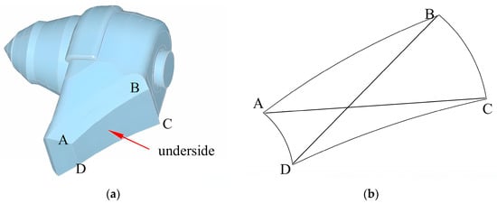
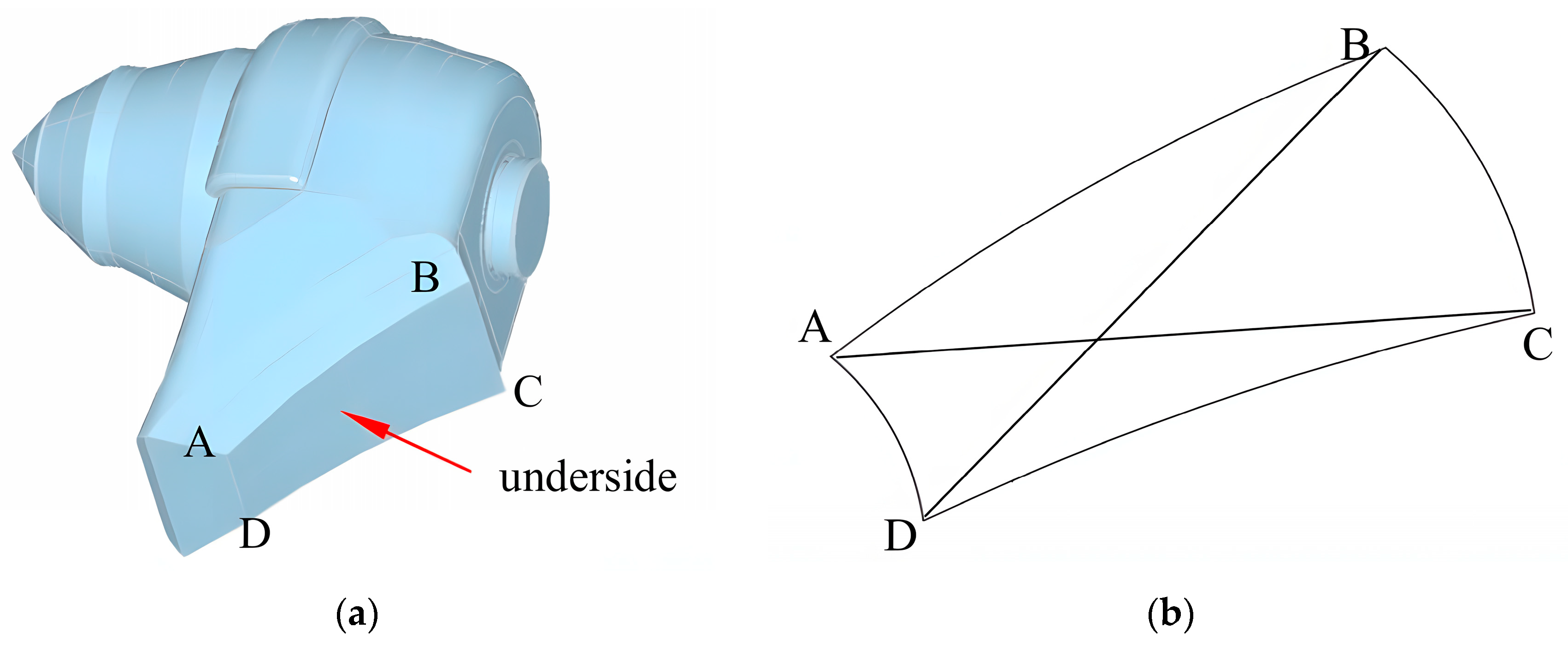
As shown in Figure 2, to achieve the precise design of the compensation body, it is first necessary to accurately extract the base surface of the tooth socket as the reference surface for subsequent geometric construction. The shape of the tooth base bottom is determined, and its diagonal length is known. Based on this premise, the task of identifying the bottom is transformed into a geometric constraint satisfaction problem. Traversing the surface of the tooth base model: For each surface, first determine the number of corners and filter out all surfaces with four corners. For each filtered surface, the 3D coordinates of its four vertices are extracted. Then, calculate and verify whether the diagonal lengths AC and BD meet the geometric conditions at the same time. If and only if a candidate surface meets the above geometric conditions at the same time, this surface is the bottom surface of the tooth base to be found. Finally, extract this bottom surface from the model. The automatically extracted base surface directly determines the starting point and direction for the subsequent surface extrapolation, ensuring the geometric continuity and smoothness between the generated extrapolation surface of the compensation body and the tooth socket itself.
Figure 2.
Holder base surface extraction. (a) Pick holder model. (b) Holder base surface.
The equation of the tooth base bottom is
where Ci,j are control points, forming the control grid. wi,j are the weight factors of the corresponding control points. Ni,3(u) and Nj,3(v) are cubic and cubic B-spline basis functions defined on node vectors U and V, respectively, and N and M are the upper index limits of control points in the u and v directions, respectively.
2.2. Surface Discretization
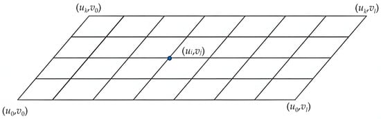
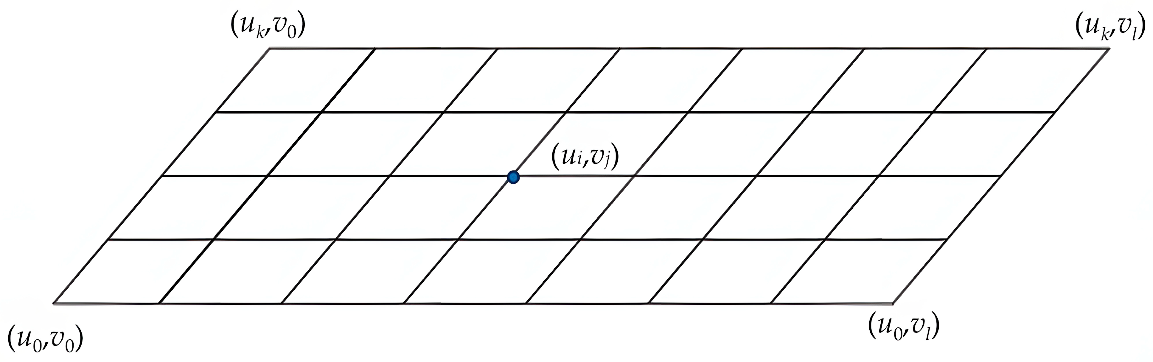
To facilitate subsequent surface extrapolation, the NURBS surface is converted into a discrete point set using a uniform subdivision method of the parameter domain [24]. The NURBS surface parameter domain is a normalized rectangular region with u ∈ [0, 1], v ∈ [0, 1]. As shown in Figure 3, the parameter domain is discretized by uniformly subdividing along the u and v directions to generate a discrete grid of parameter nodes. The following formulas are given:
where k and l are the number of partitions in the U direction and V direction, respectively.
Figure 3.
Parameter domain discretization.
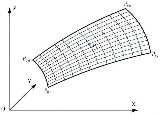
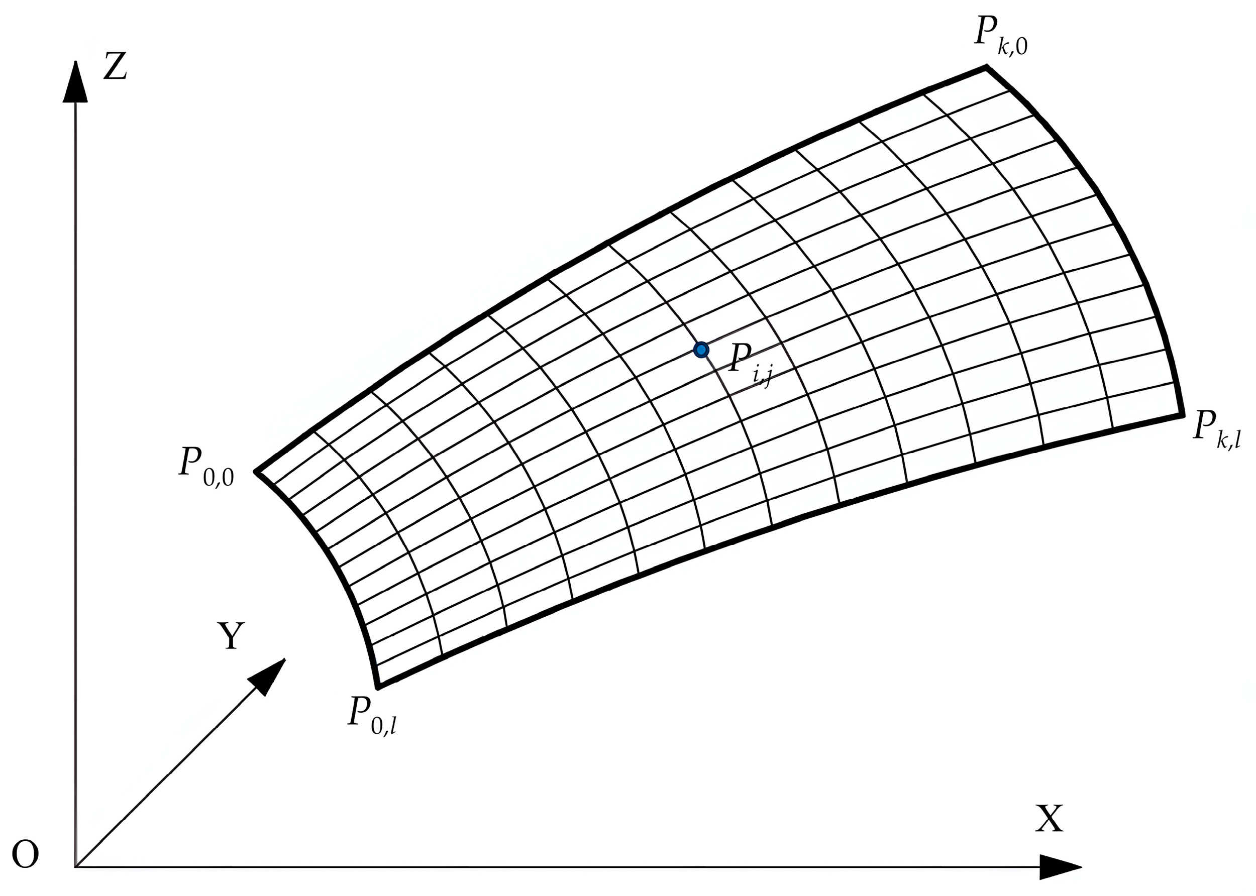
As shown in Figure 4, based on the discrete parameter pairs (ui,vj), a coordinate system OXYZ is established. Substituting (ui,vj) into Equation (1) yields the discrete point set Pi,j of the free-form surface:
Figure 4.
NURBS surface discretization.
2.3. Curve Point Sequence Continuation
In order to ensure the stress of the compensation body and facilitate welding, it is necessary to extend the bottom surface of the gear seat [25] to generate a new extrapolation surface. It is complex to operate directly on the whole surface domain. Based on the three-dimensional point set obtained by surface discretization, the extrapolation is carried out. This method converts surface extrapolation into point extrapolation.
Take i = s in the discrete three-dimensional point set Pi,j to extract the corresponding point sequence:
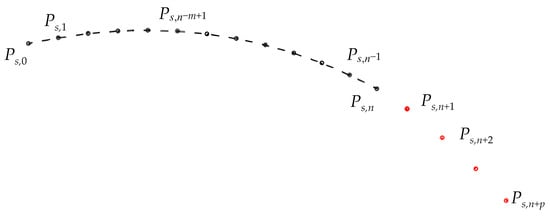
The above-mentioned point sequence is an ordered point sequence, as shown in Figure 5. The value of Ps,n+1 of any point has a certain linear correlation with the first m points Ps,n−m+1, Ps,n−m+2,…, Ps,n. Then, the approximate value of Ps,n+1 can be predicted according to the values of Ps,n−m+1, Ps,n−m+2,…, Ps,n
where wn(t) (t = 0, 1, …, m − 1) is a linear weighting factor, whose size is determined by the correlation degree between Ps,n−t, Ps,n+1 and satisfies
Figure 5.
Unidirectional point sequence extrapolation.
Let Wn = {wn(0), wn(1),…, wn(m − 1)}T, Qn = {Ps,n, Ps,n−1,…, Ps,n−m+1}T, Equation (5) can be rewritten as
The prediction error en is
When the minimum mean square deviation ξ = E{e2n} reaches the minimum, the predicted value is the best. Find the gradient of ξ and make it 0; then there is
Take the expected value of Equation (9) and rewrite it into matrix form:
where Rp = E{Qn·QTn}; r = E{Qn·Pn+1}.
The weighting factor wn is obtained from Equation (10), and then Ps,n+1 and en can be obtained. Similarly, Ps,n+2, Ps,n+3,…, Ps,n+p and en+1, en+2, …, en+p can be obtained.
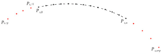
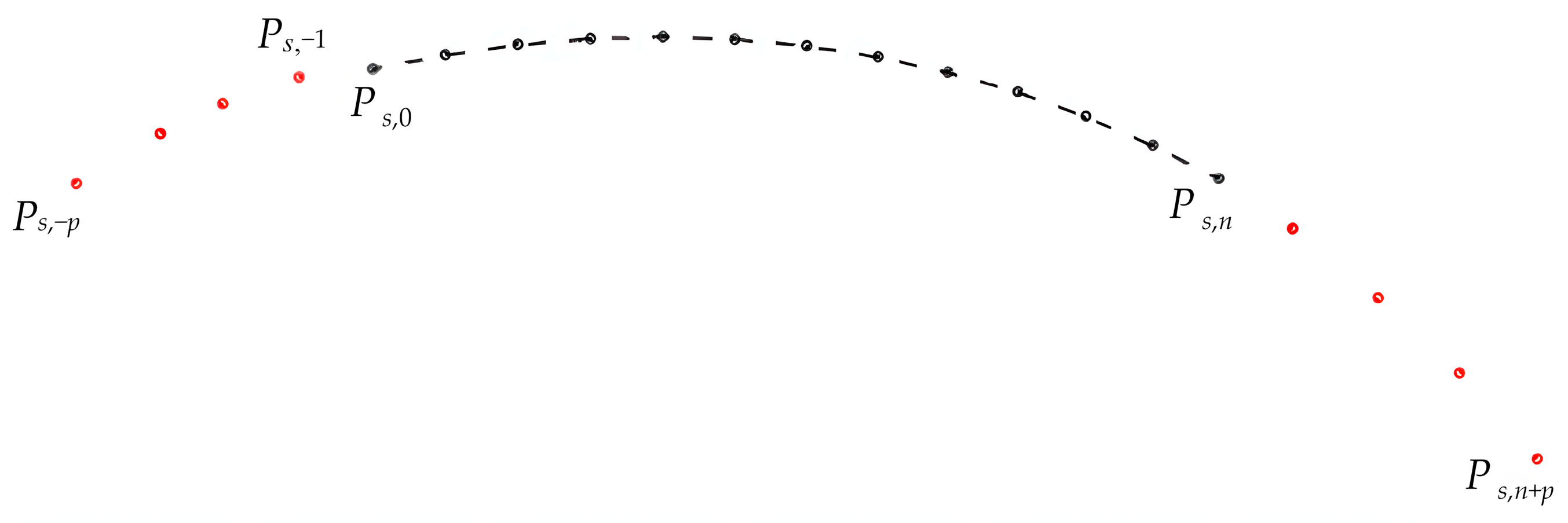
Similarly, Ps,−1, Ps,−2, …, Ps,−p and e−1, e−2, …, e−p can be obtained according to the above method, so as to realize the bidirectional extrapolation of the point sequence, as shown in Figure 6.
Figure 6.
Bidirectional point sequence extrapolation.
2.4. Surface Point Sequence Continuation
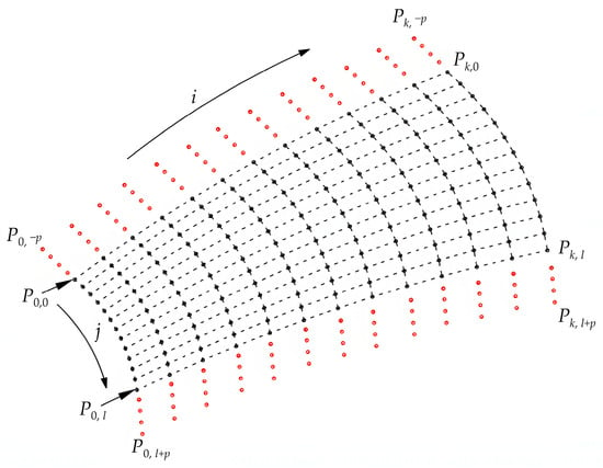
The above method realizes the extrapolation of a single point sequence (fixed i = s), and then extends it to each column of the discrete three-dimensional point set Pi,j, as shown in Figure 7, so as to realize the extrapolation of all column point sets in i direction, and expand the value range of j from 0, 1, …, l to −p, …, −1, 0, 1, …, l, …, l + p.
Figure 7.
Point set extrapolation in the i-direction.
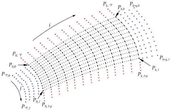
Similarly, applying the single point sequence extrapolation method to the j-direction point sequence can realize the extrapolation of all point sequences in the j-direction of Pi,j, and expand the value range of i from 0, 1, … k to −q, …, −1, 0, 1, …, k, …, k + q, as shown in Figure 8.
Figure 8.
Point set extrapolation in the j-direction.
2.5. Surface Corner Processing
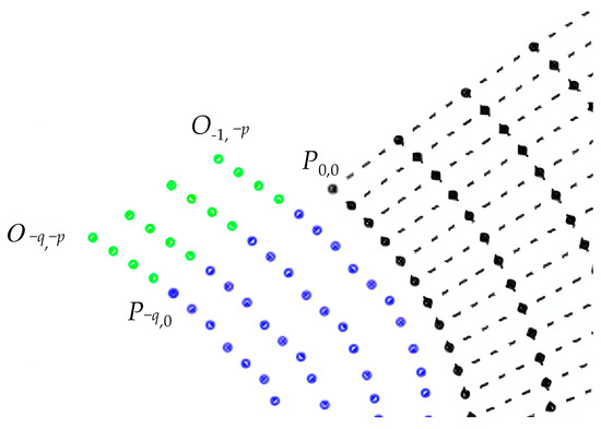
The above method realizes the bidirectional extrapolation of all the point sequences in the i and j directions of Pi,j, but the point information of corner regions, such as i < 0 and j < 0, i < 0 and j > l, is missing, which makes it impossible to directly fit and obtain a complete extrapolation surface. As shown in Figure 9, for the corner regions of i < 0 and j < 0, obtain the point sequence of i = −q, …, −1, and then use the curve point sequence extrapolation method mentioned above to extend each column to obtain the corner point set {Oi,j|i = −q, …, −1; j = −p, …, −1}.
Figure 9.
Corner extrapolation in the i-direction.
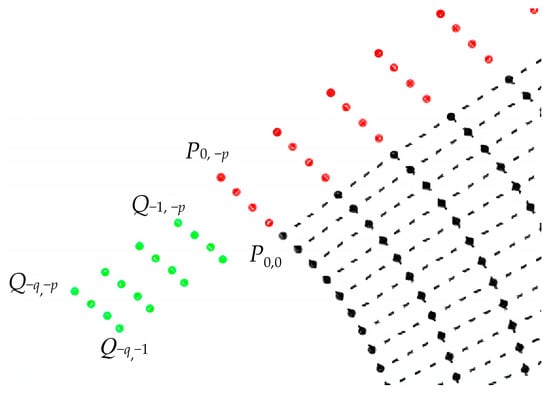
As shown in Figure 10, for the corner area with i < 0 and j < 0, obtain the point sequence of j = −p, …, −1, and then use the curve point sequence continuation method mentioned above to extend each column to obtain the corner point set {Qi,j|i = −q, …, −1; j = −p, …, −1}.
Figure 10.
Corner extrapolation in the j-direction.
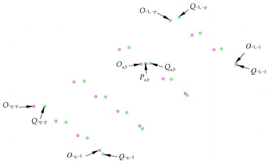
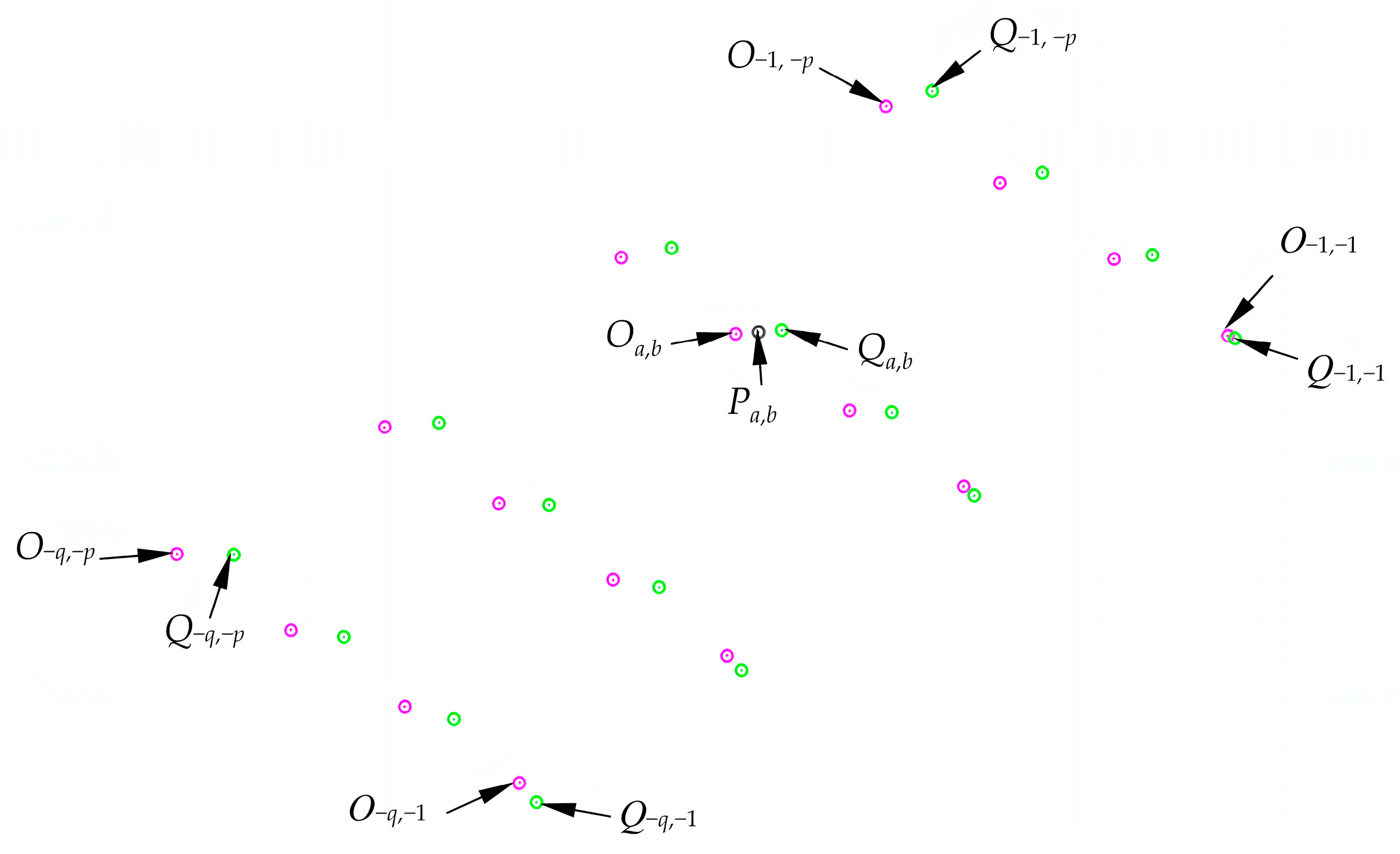
As shown in Figure 11, the corner points in the i direction and the j direction are fused. In the figure, the purple points represent the point set {Oi,j|i = −q, …, −1; j = −p, …, −1}, and the green points represent the point set {Qi,j|i = −q, …, −1; j = −p, …, −1}. Take i = a, j = b from the above two sets to get Oa,b, Qa,b, so as to calculate the final corner Pa,b:
Figure 11.
Corner fusion.
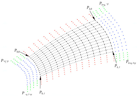
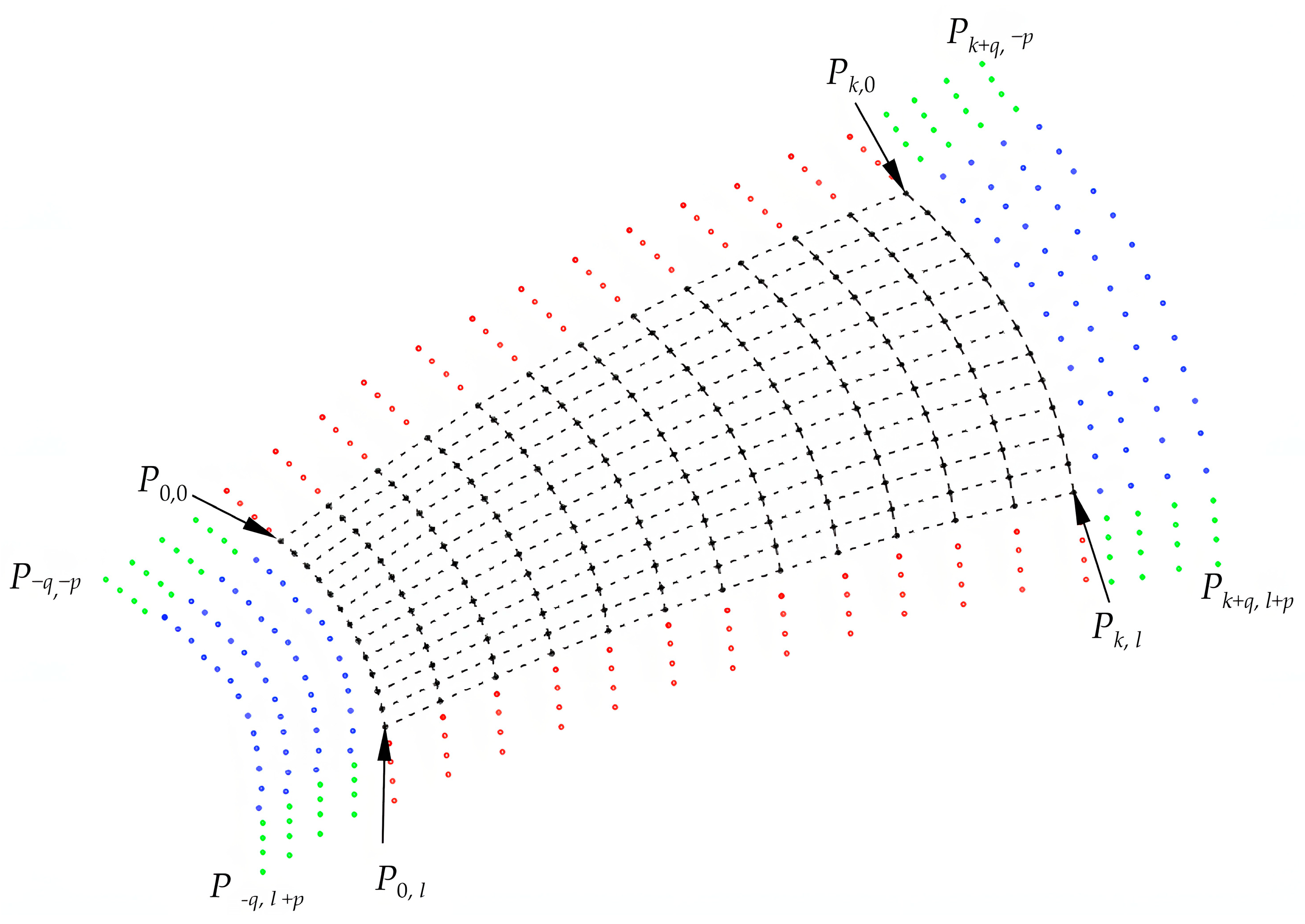
Then calculate each point in the point set Oi,j, Qi,j to get the final corner {Pi,j|i = −q, …, −1; j = −p, …, −1}. Similarly, process the other corners to complete the whole point set. As shown in Figure 12, get the extended point set {Pi,j|i = −q, …, −1, 0, 1, …, k + q; j = −p, …, −1, 0, 1, …, l + p}.
Figure 12.
Schematic of the extended point set.
2.6. Surface Fitting
To facilitate subsequent compensation body creation, a smooth parametric surface is generated from the extended point set Pi,j. Common fitting methods include direct least squares and iterative approximation. Direct least squares, which explicitly solves for control points by constructing a linear system, is simple, computationally efficient, and suitable for small-to-medium datasets. Progressive iterative approximation (PIA) and its variants iteratively update control points to approach the target data, offering better numerical stability and flexibility for large-scale, high-dimensional, or noisy data. For example, Least Squares PIA (LSPIA) avoids matrix inversion, enhancing computational robustness [26]. Further, the Full-LSPIA method simultaneously optimizes weights and knot vectors, achieving end-to-end adaptive fitting for NURBS curves/surfaces [27].
This study is oriented to the structured extrapolation point set, with moderate data size and uniform distribution, so the classical least squares B-spline surface fitting method is used. This method can effectively ensure the continuity and smoothness of the surface, and it can also be extended to a one-dimensional case for boundary curve fitting. The specific process is as follows:
Map the integer index (i,j) to the parameter (u,v) on the unit interval [0, 1]:
Thus, uniform parameterization ensures that the parameters are evenly distributed and cover the entire definition domain.
Clamped node vectors are used to ensure endpoint behavior:
u direction, node vector U′:
v direction, node vector V′:
If the number of control points is (k + 1) × (l + 1), it is required to meet the following requirements:
Defining weight coefficients:
leads to the matrix form:
where Ps ∈ R3(k+2q+1)(l+2p+1) is the data point vector, Cs ∈ R3(k+1)(l+1) is the control point vector, and Ws ∈ R(k+2q+1)(l+2p+1)×(k+1)(l+1) is the weight matrix.
Since the number of data points Pi,j exceeds the number of control points Cc,d, the system is overdetermined. The least squares solution is obtained
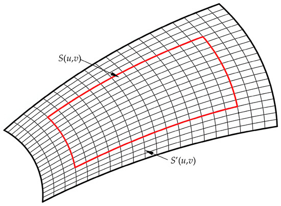
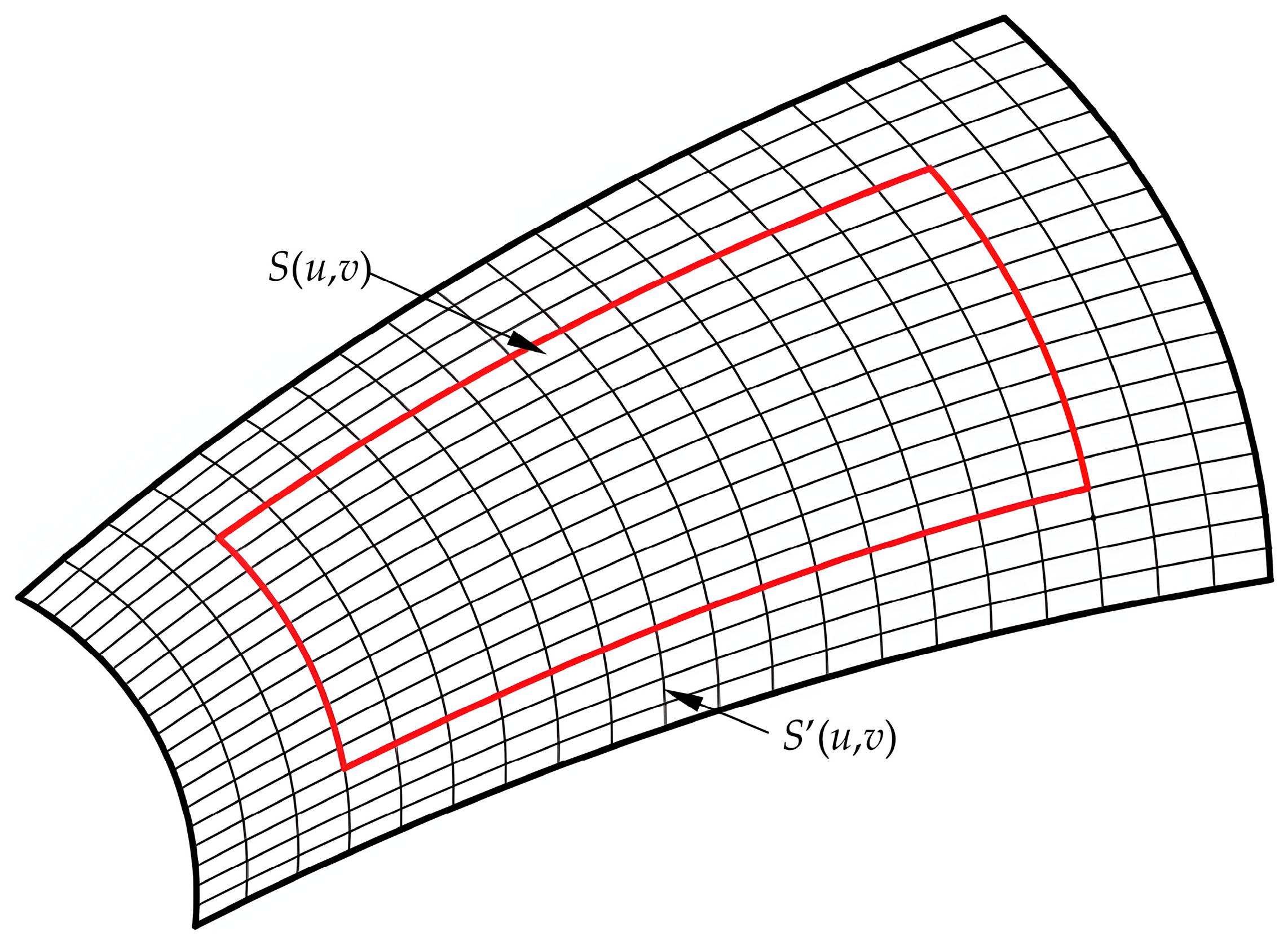
The final extended surface S′(u,v) equation is given
Figure 13 shows a schematic of the extended surface. To address the issue of insufficient effective welding area on the bottom surface of the cutting tooth, the bottom surface was expanded using a surface extrapolation method. The specific process involves starting from the initial free-form surface at the base of the tooth holder, followed by parametric discretization, B-spline curve fitting, and bidirectional extrapolation, ultimately generating an extended surface. This treatment significantly increases the welding base area, thereby providing the necessary geometric foundation to ensure connection strength and reliability.
Figure 13.
Extended surface.
3. Surface Projection and Solid Generation
In the design of the pick-drum gap compensation body, the bottom surface of the compensation body must achieve high-precision fitting with the drum surface to ensure uniform load transfer and assembly reliability. For general parametric surfaces, orthogonal point-to-surface projection typically requires iterative numerical methods [28], which are computationally expensive and can suffer from numerical instability near knots or boundaries. This paper proposes a geometry-based projection strategy: First, a parametric model of the drum is established. Then, four corner points are extracted from the extended B-spline surface to construct an approximate plane and determine a unified projection direction. Next, the boundary point sequence of the extended surface is projected along this direction onto the drum surface to obtain a boundary curve that fits precisely. Finally, based on the projected boundary and the original extended boundary, a cut surface and ruled surfaces are generated to form the compensation body. This section details the complete workflow of projection direction determination, boundary mapping, surface generation, and solid construction.
3.1. Determination of Projection Direction
The drum of the excavation machine’s cutting drum is a standard surface of revolution Sc(φ,x):
where r is the cylinder radius, φ is the circumferential angle, and x is the axial parameter.
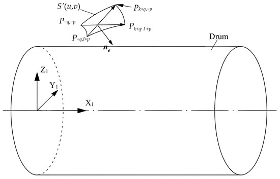
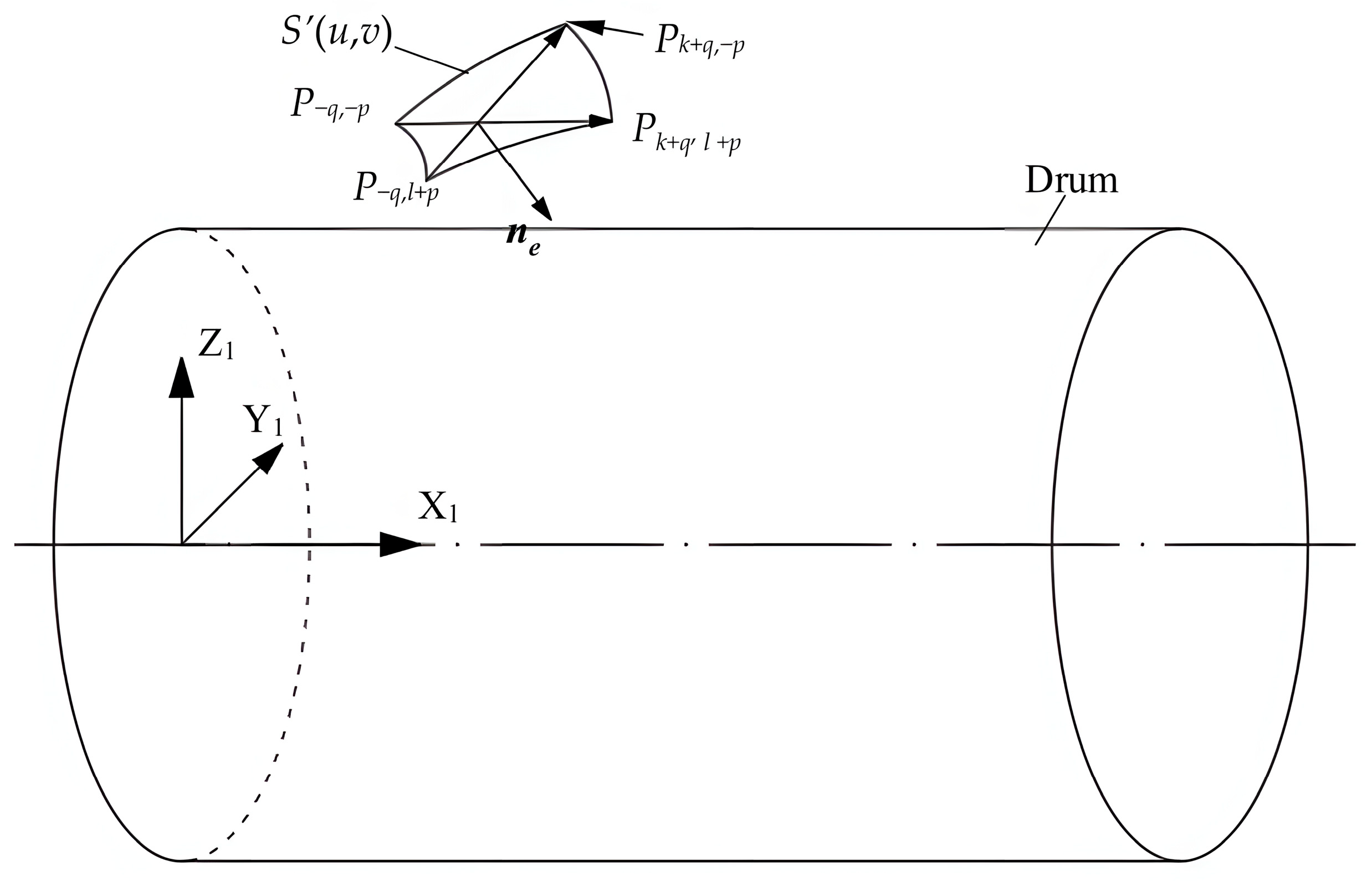
The extended surface S′(u,v) is a cubic B-spline surface. Directly computing the normal vector at every point is inefficient and potentially unstable. To improve efficiency and ensure consistency, two auxiliary vectors are constructed using the four corner points of surface S′(u,v), and their cross product determines the projection normal vector.
As shown in Figure 14, taking the four corner points P−p,−p, Pk+q,−p, P−q,l+p, Pk+q,l+p, vectors V1 and V2 are constructed:
Figure 14.
Projection direction.
Their cross product yields vector N, which is normalized to obtain the unit normal vector ne:
3.2. Boundary Point Sequence Projection
Projecting the entire extended surface directly is complex. To enhance computational efficiency, the complex surface-to-solid projection problem is transformed into a more manageable curve-to-surface projection problem.
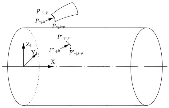
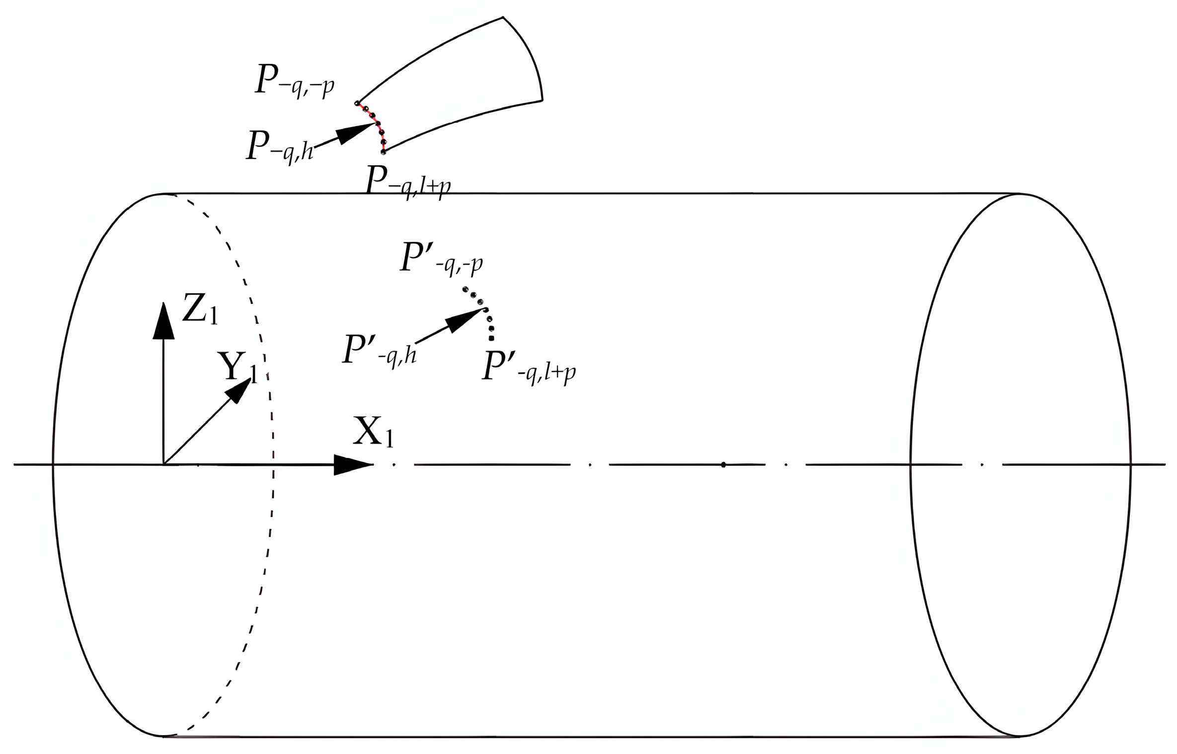
As shown in Figure 15, from the extended point set, a boundary point sequence (e.g., {P−q,l|l = −p, …, −1, 0, 1, …, l + p}) is extracted. Taking a point P−q,h(xh,yh,zh) and projecting it along ne = [nx, ny, nz]T gives the projection line equation:
Figure 15.
Boundary point sequence projection.
Substituting the y, z components into the drum surface Equation y2 + z2 = r2 yields:
Solving for the smallest positive real root λ0 and substituting back gives the projection point P′−q,h. Repeating for all points in the boundary sequence yields the new projected boundary point set {P′−q,l|l = −p,…, −1, 0, 1,…, l + p}.
3.3. Fitting of Projected Surface Boundary
Since the boundary point set is a one-dimensional ordered sequence, its fitting process is a simplified version of the surface fitting method in a single-parameter domain. Specifically, let the target curve be:
where Ni,3(τ) is the cubic B-spline basis function defined on knot vector U.
Uniform parameterization is used, and a clamped knot vector is constructed. Denoting the basis function values as weights w, a linear system Pc = WcCc is formed. This overdetermined system is solved using least squares:
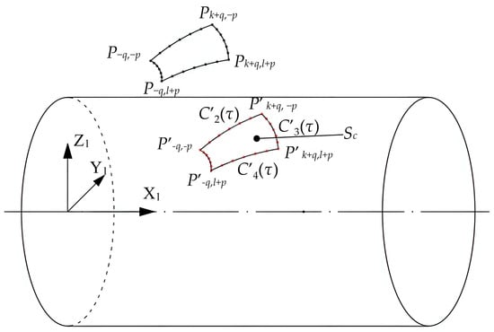
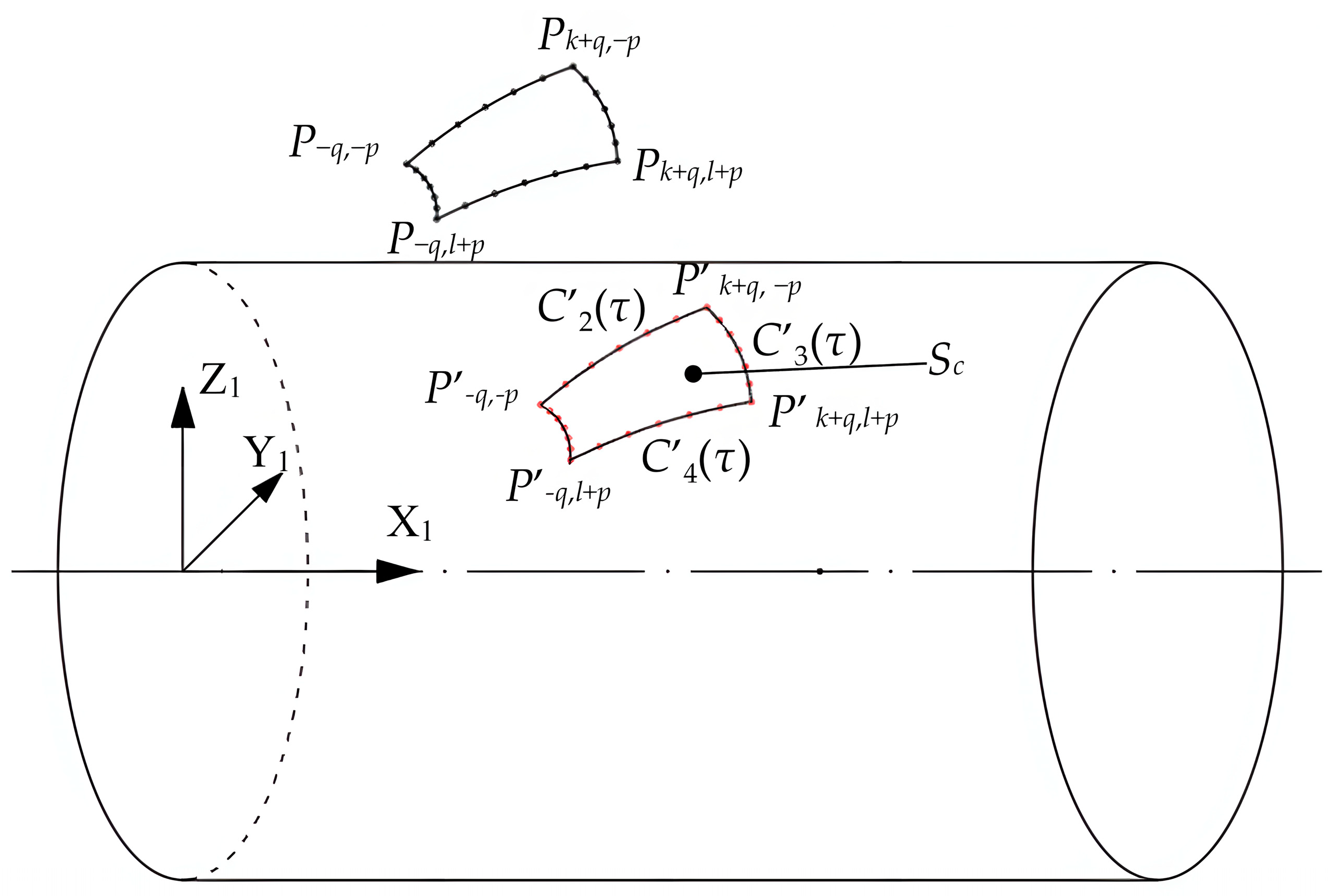
Substituting the solved control points Ci back gives the fitted curve C′1(τ) [29]. The same process is applied to the other boundary point sequences, as shown in Figure 16, yielding the remaining boundary curves C′2(τ), C′3(τ), and C′4(τ). Using these curves as boundaries, the drum surface is trimmed to obtain the cut surface Sc.
Figure 16.
Surface boundary projection.
3.4. Ruled Surface Creation
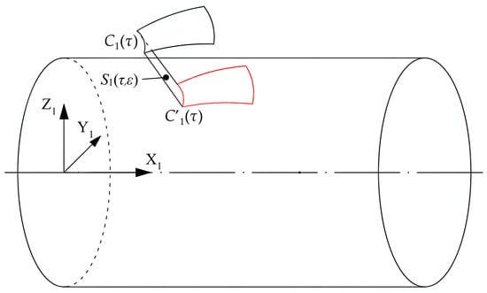
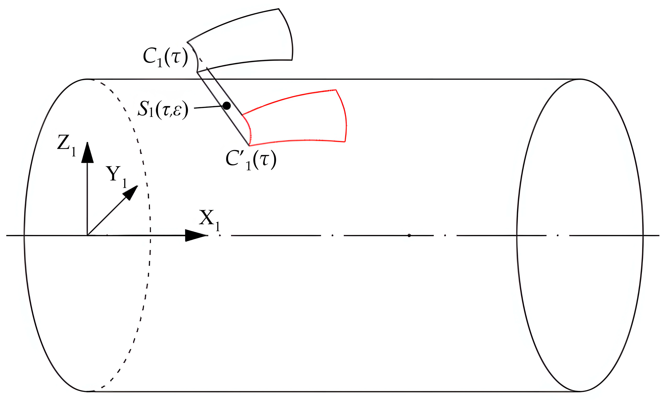
As shown in Figure 17, using the extended boundary point sequence yields the fitted curve C1(τ). Connecting corresponding points on C1(τ) and C′1(τ) creates the ruled surface S1(τ,ε). Its parametric equation is:
where ε ∈ [0, 1] and τ ∈ [0, 1].
Figure 17.
Ruled surface creation.
3.5. Solid Generation
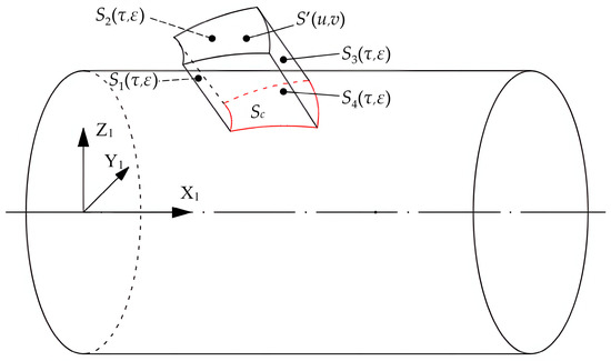
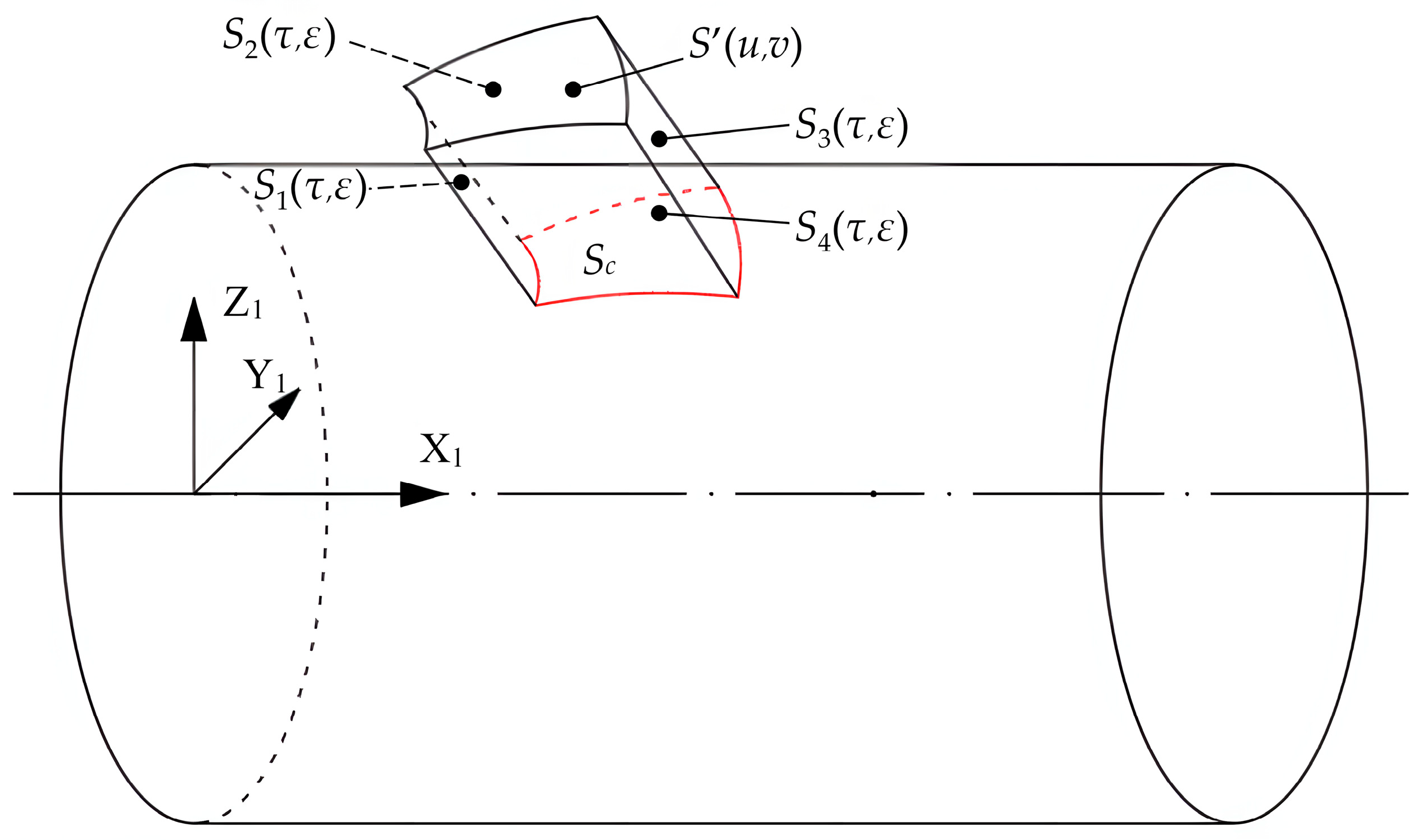
As shown in Figure 18, using the extended boundary curves and the projected boundary curves, ruled surfaces S2(τ,ε), S3(τ,ε), and S4(τ,ε) are generated. These, together with the extended surface S′(u,v), the cut surface Sc, and the ruled surfaces S1(τ,ε), are stitched together to form the closed compensation body solid.
Figure 18.
Solid generation.
4. Design Instance of Gap Compensation Body
To validate the algorithmic efficiency and engineering applicability of the gap compensation body design method proposed earlier, this section conducts an exemplary design verification using the base surface of the cutter drum tooth seat on the bolter miners as the subject.
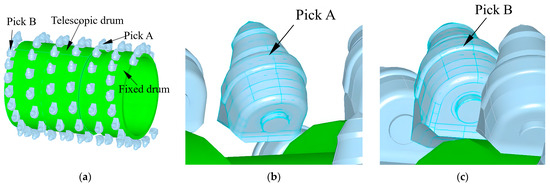
As shown in Figure 19a, this is the pick arrangement model of a bolter miner drum, primarily consisting of the fixed drum, the telescopic drum, and the picks. The outer diameter of both the fixed drum and the telescopic drum is 1200 mm. To verify the algorithm’s practicality, two picks were selected for validation. Figure 19b shows an enlarged view of Pick A, located in the telescopic section between the fixed and telescopic drums, where the pick is suspended. Figure 19c shows Pick B, situated at the edge of the drum and partially suspended. Its posture required adjustment (tilting), which subsequently created an assembly gap between the pick and the drum body, necessitating the addition of a compensation body.
Figure 19.
Pick arrangement model of the bolter miner drum. (a) Bolter miner drum assembly. (b) Local view of Pick A. (c) Local view of Pick B.
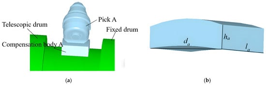
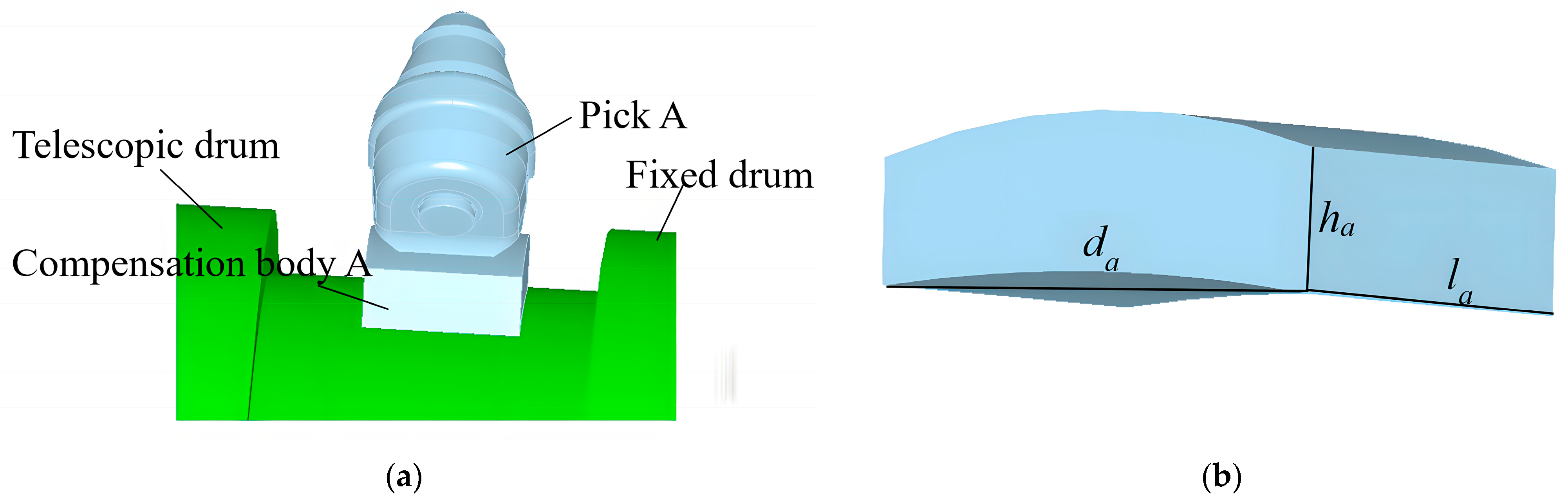
As shown in Figure 20a, Pick A is located in the telescopic section between the fixed drum and the telescopic drum. The pick is not in contact with the drum body and is completely suspended, necessitating a connection via a compensation body. Figure 20b shows Compensation Body A, with its related dimensions ha, la, and da being 38 mm, 102 mm, and 147 mm, respectively.
Figure 20.
Instance of compensation body for Pick A. (a) Gap filling for Pick A. (b) Compensation body for Pick A.
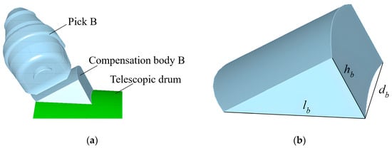
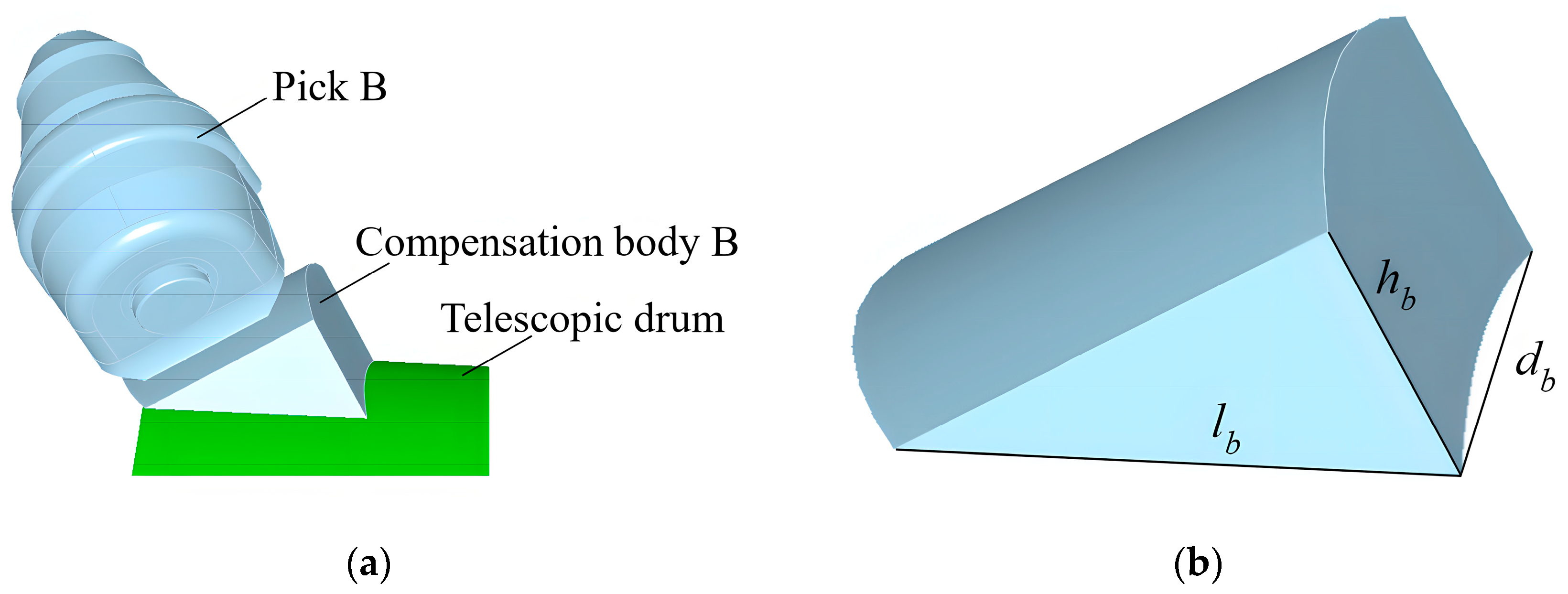
As shown in Figure 21a, Pick B is situated at the edge of the cutting drum. Before adjustment, the pick was partially suspended. To ensure its performance, its posture was adjusted, resulting in an assembly gap due to the deflection, which is filled by a compensation body. Figure 21b shows Compensation Body B, with its related dimensions hb, lb, and db being 50 mm, 100 mm, and 145 mm, respectively.
Figure 21.
Instance of compensation body for Pick B. (a) Gap filling for Pick B. (b) Compensation body for Pick B.
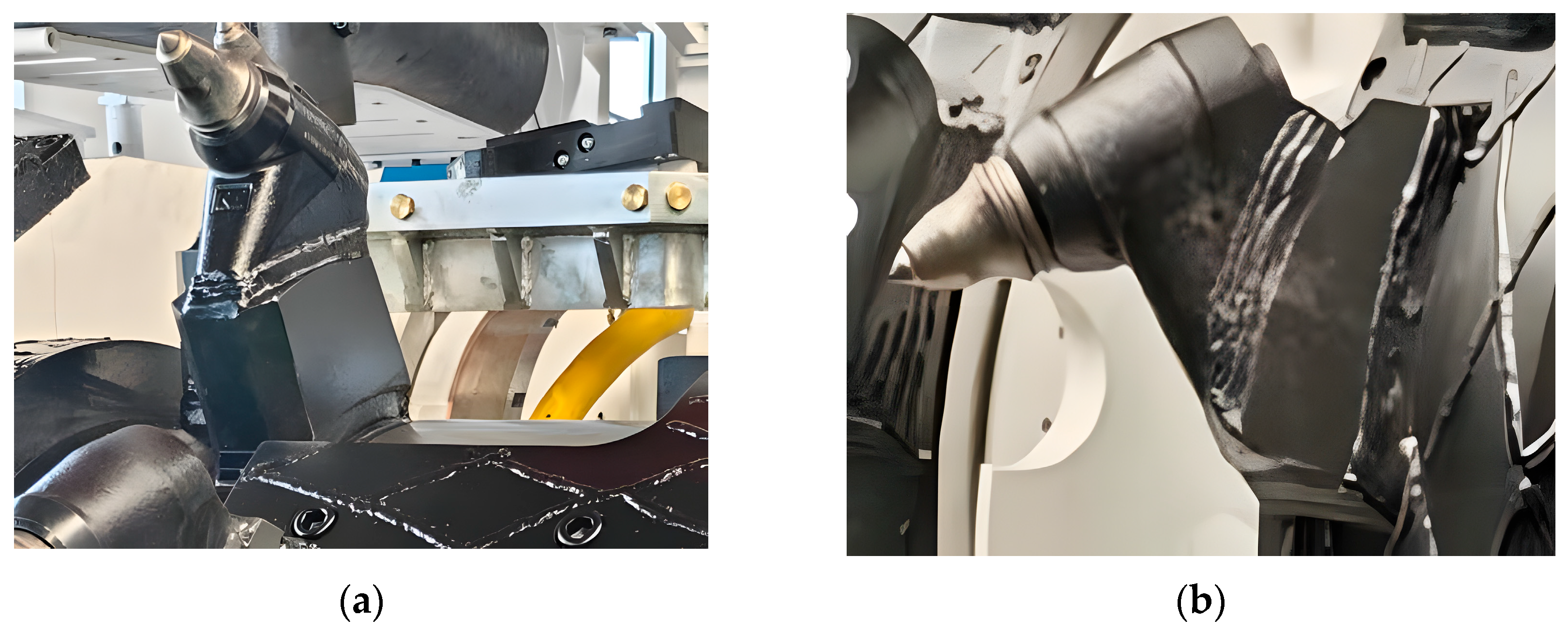
The reverse design algorithm for the pick-drum gap compensation body can automatically generate a customized 3D model based on the base surface. As shown in Figure 22a, the pick is located in the telescopic section, while Figure 22b shows a pick at the drum edge, where a gap is generated due to posture adjustment. The pick and the drum body are connected via a compensation body.
Figure 22.
Physical compensation bodies for pick-drum assembly gaps. (a) Compensation body for telescopic section pick. (b) Compensation body for partially suspended pick.
5. Conclusions
In response to the non-repetitive and geometrically unique free-form assembly gaps formed between the tooth seat and the drum cylinder in bolter miner cutting drums due to variations in installation posture, this paper proposes an automatic generation method for compensation bodies based on computer-aided design. Through surface extension, boundary projection, and ruled surface construction, the traditional experience-dependent, difficult-to-reproduce manual design process is transformed into a computable and parameterizable deterministic workflow. Based on theoretical modeling, algorithmic implementation, and case verification, the main conclusions of this study are as follows:
- A serialized geometric modeling framework for dual-surface gaps has been established. The core of the method lies in proposing an ordered computational process comprising discrete extension, curve projection, and ruled surface construction. First, parametric domain discretization sampling is performed on the tooth seat bottom surface, and a smooth extension surface is generated based on cubic B-spline fitting and bidirectional extension, serving as the top surface of the compensation body. Second, the complex surface projection is simplified into the normal projection of boundary curves onto the cylindrical rotating surface, accurately determining the bottom surface of the compensation body. Finally, using the extension boundary and the projected boundary as guide curves, ruled transition surfaces are constructed to complete the solid generation. This workflow enables automated and parametric modeling of such statistically irregular and unique gaps.
- Adaptive generation of compensation bodies and high-precision dual-interface fitting have been achieved, significantly enhancing connection reliability. The algorithm can automatically adapt to the spatial posture of each tooth seat, generating customized compensation bodies that fully match their local gap morphology. The resulting models maintain continuous contact with both the free-form surface of the tooth seat and the rotating surface of the drum cylinder, substantially improving connection strength.
- Significant breakthroughs have been made in design efficiency, quality consistency, and process feasibility. Compared to traditional manual CAD modeling, this method enables rapid batch generation of compensation bodies for an entire drum, with a marked improvement in efficiency. The procedural workflow completely eliminates human intervention, ensuring consistent accuracy across compensation bodies at different positions. Furthermore, the extended surface increases the effective welding area, significantly reducing welding difficulty.
- The engineering applicability of the method has been verified, and directions for further development have been outlined. Validation using cutting picks under typical installation conditions, such as suspended and tilted positions, shows that the method exhibits good adaptability to tooth seat bottom surfaces in various postures. The output models can interact with mainstream CAD/CAM software, facilitating subsequent process planning, simulation analysis, and manufacturing programming.
In summary, this study addresses the dual-surface gap problem caused by installation posture variations in cutting drums by proposing a serialized geometric modeling strategy, successfully shifting compensation design from experience-driven manual methods to algorithm-driven automation. This method not only provides technical support for the highly reliable assembly of key components in bolter miners but also offers a transferable and scalable digital design framework for the intelligent compensation of unique gaps between complex surfaces, a challenge prevalent in the field of mechanical equipment.
Author Contributions
Conceptualization, X.L. and J.L.; methodology, X.L.; software, X.L. and M.L.; validation, J.L. and T.Y.; formal analysis, X.L.; investigation, X.L.; resources, T.Y.; data curation, X.L.; writing—original draft preparation, X.L.; writing—review and editing, J.L. and X.L.; visualization, X.L.; supervision, T.Y.; project administration, T.Y.; funding acquisition, T.Y. All authors have read and agreed to the published version of the manuscript.
Funding
This research received no external funding.
Institutional Review Board Statement
Not applicable.
Informed Consent Statement
Not applicable.
Data Availability Statement
The original contributions presented in this study are included in the article. Further inquiries can be directed to the corresponding author.
Conflicts of Interest
The authors declare no conflicts of interest.
References
- Zhao, Y.; Zhao, Y.; Zhou, Z. Research Status of Intelligent Technology of Shearer in Fully Mechanized Working Face. Ind. Mine Autom. 2022, 48, 11–28. [Google Scholar] [CrossRef]
- Wang, G. New Technological Progress of Coal Mine Intelligence and Its Problems. Coal Sci. Technol. 2022, 50, 1–27. [Google Scholar]
- Wang, G.; Xu, Y.; Zhao, J.; Ma, Y. New Development of Intelligent Mining in Coal Mines. Coal Sci. Technol. 2021, 49, 1–10. [Google Scholar] [CrossRef]
- Jiskani, I.M.; Zhou, W.; Hosseini, S.; Wang, Z. Mining 4.0 and climate neutrality: A unified and reliable decision system for safe, intelligent, and green & climate-smart mining. J. Clean. Prod. 2023, 410, 137313. [Google Scholar] [CrossRef] [Scilit]
- Wang, X.; Bai, Y.; Zou, X.; Yang, X.; Chen, H. Research on Indirect Measurement and Estimation Method of Shearer Drum Cutting Load. Alex. Eng. J. 2023, 65, 939–949. [Google Scholar] [CrossRef] [Scilit]
- Li, X.; Wang, S.; Ge, S.; Malekian, R.; Li, Z. A Study on Drum Cutting Properties with Full-Scale Experiments and Numerical Simulations. Measurement 2018, 114, 25–36. [Google Scholar] [CrossRef] [Scilit]
- Eshaghian, O.; Hoseinie, S.H.; Salimi Jazi, H. Effects of Ni-based composite coatings on failure mechanism and wear resistance of cutting picks on coal shearer machine. Eng. Fail. Anal. 2023, 151, 107342. [Google Scholar] [CrossRef] [Scilit]
- Ammar, M.M.A.; Shirinzadeh, B.; Zhao, P.; Shi, Y. Optimization of Process-Induced Residual Stresses in Automated Manufacturing of Thermoset Composites. Aerosp. Sci. Technol. 2022, 123, 107743. [Google Scholar] [CrossRef] [Scilit]
- Kannan, S.M.; Raja Pandian, G. A New Selective Assembly Model for Achieving Specified Clearance in Radial Assembly. Mater. Today Proc. 2021, 46, 7411–7417. [Google Scholar] [CrossRef] [Scilit]
- Yue, X.; An, L.; Ye, X.; Wang, C.; Cai, Y. Effect of Gap and Shims on the Strain and Stress State of the Composite-Aluminum Hybrid Bolted Structure. Int. J. Aerosp. Eng. 2020, 2020, 8811484. [Google Scholar] [CrossRef] [Scilit]
- Cheng, L.; Wang, Q.; Ke, Y. Experimental and Numerical Analyses of the Shimming Effect on Bolted Joints with Nonuniform Gaps. Proc. Inst. Mech. Eng. Part C J. Mech. Eng. Sci. 2019, 233, 3964–3975. [Google Scholar] [CrossRef] [Scilit]
- Huehne, C.; Zerbst, A.; Kuhlmann, G.; Steenbock, C.; Rolfes, R. Progressive Damage Analysis of Composite Bolted Joints with Liquid Shim Layers Using Constant and Continuous Degradation Models. Compos. Struct. 2010, 92, 189–200. [Google Scholar] [CrossRef] [Scilit]
- Yang, Y.; Wang, Y.Q.; Liu, X.; Gao, H.; Bao, Y. The Effect of Shimming Material on Flexural Behavior for Composite Joints with Assembly Gap. Compos. Struct. 2019, 209, 375–382. [Google Scholar] [CrossRef] [Scilit]
- Sun, Z.; Pan, Z.; Shangguan, J.; Wang, H.; Han, X. A Posture Alignment-Based Methodology for Gap Optimization of Aircraft Composite Panel Assembly. Aerosp. Sci. Technol. 2023, 140, 108442. [Google Scholar] [CrossRef] [Scilit]
- Caputo, A.C.; Di Salvo, G. An Economic Decision Model for Selective Assembly. Int. J. Prod. Econ. 2019, 207, 56–69. [Google Scholar] [CrossRef] [Scilit]
- Mencaroni, A.; Claeys, D.; De Vuyst, S. A Novel Hybrid Assembly Method to Reduce Operational Costs of Selective Assembly. Int. J. Prod. Econ. 2023, 264, 108966. [Google Scholar] [CrossRef] [Scilit]
- Cui, L.; Zhu, L.; Yang, Y. Research and Application of Gap Filling Repair Technology for Wind Turbine Tower Flange. Ship Eng. 2024, 46, 19–26. (In Chinese) [Google Scholar]
- Uyar, K.; Ülker, E. B-spline curve fitting with invasive weed optimization. Appl. Math. Model. 2017, 52, 320–340. [Google Scholar] [CrossRef] [Scilit]
- Amiri-Simkooei, A.; Esmaeili, F.; Lindenbergh, R. Least squares B-spline approximation with applications to geospatial point clouds. Measurement 2025, 248, 116887. [Google Scholar] [CrossRef] [Scilit]
- Vallisa, L.; Laboureur, D.; Scelzo, M.T.; Lopes, S.; De Paepe, M. A novel interface reconstruction method based on B-Spline parametric surfaces: Application to free-falling natural particle in thermo-buoyant flows. Comput. Fluids 2025, 30, 106843. [Google Scholar] [CrossRef] [Scilit]
- Gao, J.; Wen, H.; Lin, Z.; Wu, H. Geometric Model Reconstruction through a Surface Extrapolation Algorithm for Remanufacturing of Twist Blades. Rapid Prototyp. J. 2017, 23, 382–390. [Google Scholar] [CrossRef] [Scilit]
- Song, Q.; Bo, P. Newton Geometric Iterative Method for B-Spline Curve and Surface Approximation. Comput. Aided Des. 2024, 172, 103716. [Google Scholar] [CrossRef] [Scilit]
- Song, H.C.; Yong, J.H.; Yang, Y.J.; Liu, X.M. Algorithm for Orthogonal Projection of Parametric Curves onto B-Spline Surfaces. Comput. Aided Des. 2011, 43, 381–393. [Google Scholar] [CrossRef] [Scilit]
- Austin, S.P.; Jerard, R.B.; Drysdale, R.L. Comparison of Discretization Algorithms for NURBS Surfaces with Application to Numerically Controlled Machining. Comput. Aided Des. 1997, 29, 71–83. [Google Scholar] [CrossRef] [Scilit]
- Naples, N.J.; Allen, Y.Y. Toolpath Generation for Ultraprecision Machining: Freeform Surface Generation and Extrapolation. Precis. Eng. 2023, 80, 290–301. [Google Scholar] [CrossRef] [Scilit]
- Deng, C.; Lin, H. Progressive and Iterative Approximation for Least Squares B-Spline Curve and Surface Fitting. Comput. Aided Des. 2014, 47, 32–44. [Google Scholar] [CrossRef] [Scilit]
- Lan, L.; Ji, Y.; Wang, M.Y. Full-LSPIA: A Least-Squares Progressive-Iterative Approximation Method with Optimization of Weights and Knots for NURBS Curves and Surfaces. Comput. Aided Des. 2024, 169, 103673. [Google Scholar] [CrossRef] [Scilit]
- Selimovic, I. Improved Algorithms for the Projection of Points on NURBS Curves and Surfaces. Comput. Aided Geom. Des. 2006, 23, 439–445. [Google Scholar] [CrossRef] [Scilit]
- Chung, K.L.; Yan, W.M. A Fast Algorithm for Cubic B-Spline Curve Fitting. Comput. Graph. 1994, 18, 327–334. [Google Scholar] [CrossRef] [Scilit]

Disclaimer/Publisher’s Note: The statements, opinions and data contained in all publications are solely those of the individual author(s) and contributor(s) and not of MDPI and/or the editor(s). MDPI and/or the editor(s) disclaim responsibility for any injury to people or property resulting from any ideas, methods, instructions or products referred to in the content. |
© 2026 by the authors. Licensee MDPI, Basel, Switzerland. This article is an open access article distributed under the terms and conditions of the Creative Commons Attribution (CC BY) license.