


Abstract
In transient high-pressure gas rock breaking, resilient sealing materials can reduce energy loss during rock breaking and ensure the effectiveness and safety of the operation. This study, utilizing experimental data and finite element analysis, investigates the impact of transient high-pressure gas on sealing methods. It compares the traditional single-layer concrete sealing with a novel three-stage concrete sealing method, highlighting its advantages. Furthermore, a three-stage approach is used to analyze the mechanical evolution of different sealing layers, and the sealing mechanism is revealed through energy-absorption analysis. Research findings indicate that the traditional single-layer concrete sealing method experiences severe damage, with a maximum damage value of 0.26. In contrast, the three-stage sealing method exhibits significantly less damage (mostly < 0.2), effectively improving sealing efficiency. The three-stage sealing method generally demonstrates lower stress levels compared to the single-layer concrete sealing method. After passing through the gravel and soil layers, the impact-induced stress becomes relatively stable, with stress levels at the center gradually approaching those at the hole’s walls. The central portion of the gravel layer shows a greater energy absorption effect than the two boundary areas, while the soil layer exhibits a linear relationship between deformation and energy absorption. The three-stage sealing method weakens the impact through a structural approach of “pressure-absorption-pressure”, where the gravel layer primarily disperses pressure, while the soil layer provides energy absorption and cushioning. The research findings have significant implications for the safe application of transient high-pressure gas rock breaking technology.
1. Introduction
In rock engineering, mechanical rock breaking is characterized by low efficiency, poor results, and high costs [1]. Explosive blasting, on the other hand, is associated with issues such as a wide range of vibration effects, the generation of harmful gases, and potential hazards to the physical and mental health of workers [2,3]. In contrast, transient high-pressure-gas impact rock breaking, due to its lack of hazardous materials and lower costs associated with transportation and storage, has gained increasing attention as a more efficient and safer method for rock breaking in recent years. During the process of transient high-pressure-gas rock breaking, traditional cement grouting sealing methods can result in blowout of the sealing material from the weaker sealing surface due to the impact of high-pressure gas. Blowout can pose significant risks, including damage to operational machinery, the surrounding environment, and even harm to individuals in the vicinity. Therefore, researching effective methods to prevent blowout and securely contain transient high-pressure gas is of paramount importance for the safe application of transient high-pressure-gas rock-fracturing technology.
Currently, in rock breaking and sealing processes, the primary methods used for sealing include materials such as sand, gypsum, and cement grouting [4,5,6]. The above-mentioned sealing methods are primarily used in rock-blasting processes, which differ from the transient high-pressure-gas fracturing process in that the latter requires more time to release high-pressure gas [7,8]. Consequently, the sealing requirements are higher for transient high-pressure gas fracturing, and the aforementioned sealing methods are prone to issues such as blowouts when applied in this context. Therefore, it is essential to investigate the damage characteristics of the sealing layer under the impact of transient high-pressure gas to develop a sealing method with stronger impact resistance.
Some researchers have studied the damage to concrete materials under transient impact forces. Sun et al. [9] investigated the fatigue performance of concrete under various cyclic stress levels and observed a logarithmic linear correlation between strain rate, dissipated energy, and the fatigue life of concrete. Yu et al. [10] analyzed three different failure modes of single-layer mesh domes in reinforced concrete substructures of different sizes and, based on structural damage theory, proposed criteria for determining the failure mode of single-layer mesh domes and estimating their critical load strength. Chen et al. [11], based on a three-dimensional micromechanical model, examined the impact of transverse tensile stress on the multiaxial mechanical properties of concrete and found it to accelerate concrete failure. Zhong et al. [12] used LS-DYNA R14.0.0 software to conduct numerical simulations on reinforced concrete beams with different impact velocities, longitudinal reinforcement ratios, and shear reinforcement ratios, showing that at lower speeds, higher impact velocities led to increased peak and residual displacements. Wu et al. [13] proposed a rate-dependent viscoplasticity model to describe the dynamic damage and failure behavior of concrete materials, considering the rate sensitivity in the dynamic failure and damage evolution of bonding under different tensile loading rates. The above research provides some reference for us to explore the loss and mechanical characteristics of concrete hole sealing under transient high-pressure impact. Furthermore, some researchers have also investigated the destructive effects of transient high-pressure-gas rock breaking on rock formations during transient high-pressure impact [14,15,16]. However, the aforementioned studies primarily focused on the destructive effects of transient high-pressure impact on surrounding rock formations, leaving a gap in understanding the damage effects on sealing materials under transient high-pressure impact.
In this paper, we propose a novel “three-stage” composite sealing architecture—comprising gravel, soil, and concrete—and systematically validate its superiority over the traditional single-layer concrete method. By integrating transient high-pressure gas impact experiments with explicit dynamic finite element analysis (FEA), this study elucidates the damage evolution and stress wave propagation dynamics within the sealing system. The principal innovation of this research lies in the paradigm shift from a passive “blocking” strategy to an active functional mechanism characterized by “Pressure Dispersion (Gravel)—Energy Absorption (Soil)—Rigid Sealing (Concrete).” Through a quantitative assessment of the mechanical response and energy-absorption efficiency of each functional layer, we demonstrate how this composite structure effectively decouples the high-frequency shock wave from the bottom sealing segment, thereby establishing a robust theoretical framework and practical solution for safe rock breaking in deep boreholes.
2. Methodology
2.1. Three-Stage Sealing Method
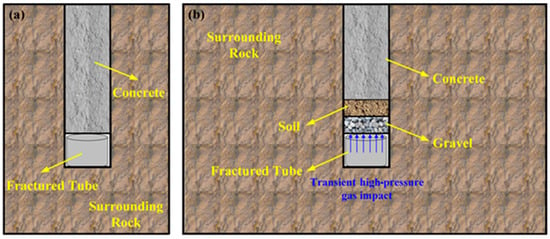
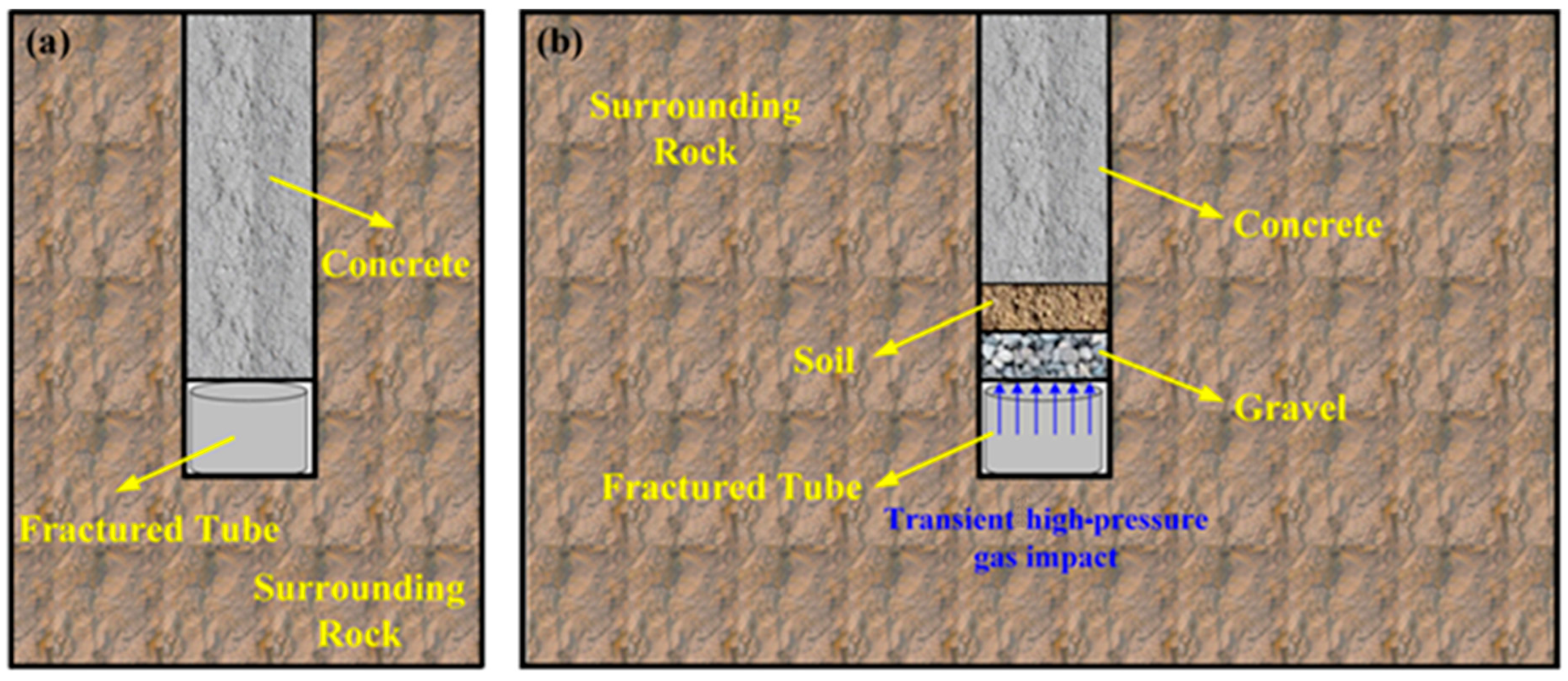
High-energy composite materials release heat through combustion in liquid CO2, resulting in the rapid release of high-pressure gas within a sealed space [17]. In order to investigate a more effective sealing technique for high-strength impact loads generated during transient high-pressure gas rock fracturing, we have introduced a novel three-stage sealing method, as illustrated in Figure 1b. The propagation of shockwaves in stratified media is influenced by the dispersion and dissipation effects of material constitutive properties, as well as the interface’s reflectivity [18]. Therefore, the use of multi-layered sealing structures with different materials can effectively attenuate shockwaves. Figure 1 compares the traditional single-layer concrete sealing method with the three-stage sealing method. Compared to the traditional sealing method, the three-stage sealing method involves filling the first layer with gravel materials, which not only provides support but also disperses the transient high-intensity impact load. The second layer is filled with soil materials to enhance resistance against transient gas impact. The third section consists of concrete materials primarily for sealing.
Figure 1.
Schematic of Sealing Methods (a) Traditional Single-Layer Concrete Sealing (b) Three-Stage Sealing.
2.2. Finite Element Method
The transient high-pressure-gas rock-breaking process is of extremely short duration, making it challenging to monitor the dynamic damage and mechanical responses of the sealing layer during rock breaking. Therefore, based on our prior experiments with high-strength concrete in a transient high-pressure-gas dynamic pulse true triaxial test system [19], coupled with finite element analysis methods, we developed numerical models to characterize the mechanical responses during the plugging processes of both traditional single-layer concrete plugging and the three-stage plugging. Subsequently, we conducted an analysis to understand the plugging mechanisms in the three-stage plugging under transient high-pressure rock breaking.
2.2.1. Sealing Model Construction
In order to investigate the effect of sealing layer under traditional single-layer concrete sealing and three-stage sealing during transient high-pressure-gas rock breaking. Additionally, the study does not consider factors related to rock and soil fissures, treating both the surrounding rock and concrete as continuous media. Furthermore, in practical engineering applications, the shape of the borehole wall has a minor impact on the sealing layer. The borehole radius is significantly smaller than its depth. Therefore, a two-dimensional longitudinal cross-section of a cylindrical borehole is chosen for modeling and analysis.
The study area encompassed a rock mass region with geometric dimensions of 6000 mm × 3000 mm. A borehole with a depth of 1000 mm and a radius of 25 mm was centrally located within the rock mass. In the traditional single-layer concrete sealing method, the borehole was filled with concrete to a depth of 1000 mm. In the three-stage sealing method, the bottom 100 mm of the borehole was filled with crushed stone, the subsequent 100 mm to 200 mm was filled with soil, and the remaining portion was filled with concrete.
2.2.2. Boundary Conditions and Parameter Settings
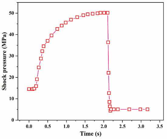
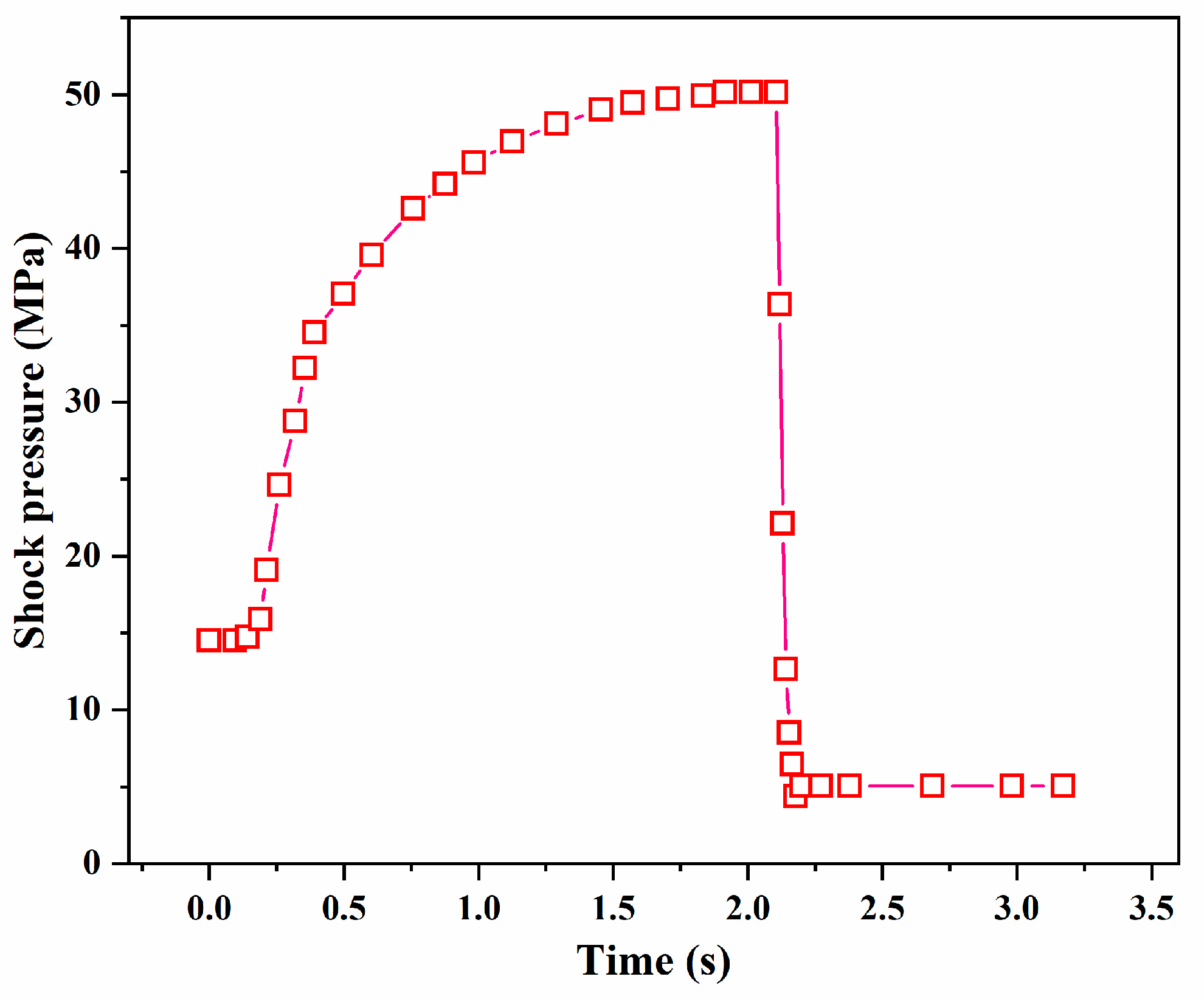
In practical engineering scenarios, the surrounding rock is considered to be infinitely large relative to the borehole. It is assumed that when subjected to transient high-pressure-gas impact, the rock on both sides of the borehole experiences a squeezing effect on the surrounding rock but only moves vertically. Additionally, the deep rocks at the bottom of the surrounding rock are not affected by the transient impact. Hence, the model was defined with roller support boundaries on both sides, a fixed displacement boundary at the bottom, and a free boundary at the top. After concrete injection into the borehole, there was adhesive force between the concrete and the borehole wall. Once solidified, it formed a continuous integral with the surrounding rock of different materials. Furthermore, the transient high-pressure-gas impact load, as obtained from previous concrete experiments, was applied at the bottom of the borehole (as shown in Figure 2). The concrete material properties were maintained in line with the high-strength concrete specimens prepared during the experiments, and the surrounding rock was considered to be granite. Specific parameters can be found in Table 1.
Figure 2.
Impact Load during Transient High-Pressure-Gas Fracturing Test.
Table 1.
Parameters of Concrete and Surrounding rock.
2.2.3. Governing Equations
It should provide a concise and precise description of the experimental results, their interpretation, as well as the experimental conclusions that can be drawn.
where is the stress vector, MPa; is the solid density, kg/m3; is the solid displacement, m; is the force per unit volume, N/m3; and is time, s.
The strain–displacement relationship for rock and concrete deformation is [20]:
where is the strain vector; is the displacement, m.
Assuming that rock and concrete are linear-elastic materials obeying the generalized Hooke’s law, the constitutive equation expresses the stress–strain relationship as:
where is the prestressing force; is the linear elasticity matrix.
The Rankine damage model is widely employed in the study of concrete damage [21,22]. This model effectively describes the damage evolution in concrete, aiding in a better understanding of the relationship between concrete’s strength and toughness [23]. The strain formulation of the Rankine damage model is based on the loading function .
where is the equivalent strain, a scalar measure of elastic strain; is the stress in concrete, MPa; and is the modulus of elasticity of concrete. as the maximum value during loading of . k is a history state variable representing the maximum equivalent strain reached during the loading process The evolution of follows the Kuhn–Tucker loading/unloading condition.
The Rankine damage model utilizes the damage variable d to characterize the destructive impact of high-pressure gas on concrete materials. Using the linear strain softening law, the damage variable d is obtained.
where is the strain at the start of damage; is the uniaxial tensile strength of concrete, MPa; is the strain corresponding to the peak stress; is the fracture energy per unit area, J/m2.
The modified Cam–Clay model reasonably and simply reflects the shear deformation and volumetric deformation characteristics of soil along the three-axis compression path [24,25,26]. The Modified Cam–Clay (MCC) model is employed to incorporate stress-dependent stiffness by filling the elastic tensor C. The elastic response (within the yield surface) can be succinctly decomposed into volumetric and deviatoric components, represented as follows [27]:
where is the elastic volumetric strain, is the elastic deviatoric strain, is the mean effective stress, q is the deviator (von Mises) stress and κ is the slope of the elastic (unload-reload) line in the v: Inp ‘plane. There is a choice as to whether to fix the shear modulus G.
There is a choice as to whether to fix the shear modulus G or the Poisson’s ratio; v is fixed here; hence the shear modulus is calculated as:
The elliptical yield surface is given by:
where M represents the slope of the critical state line on the q:p′ plane. It is assumed that the soil follows the normality condition, meaning that the plastic strain increment vector is oriented outward from the yield envelope. The plastic response is given by:
where η = q/p′ and λ and κ are the slopes (in the v: lnp ‘plane) of the normal compression line and unload-reload lines, respectively.
Combining the Hoek–Brown criterion [28], granite is characterized as gravel, with m representing the rock’s hardness and s indicating its fracturing level. Table 2 and Table 3 respectively present the parameter settings for the gravel layer and soil layer in the model.
Table 2.
Parameters of gravel.
Table 3.
Parameters of soils.
3. Results
3.1. Damage Evolution Analysis
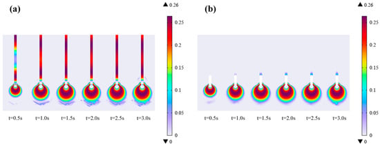
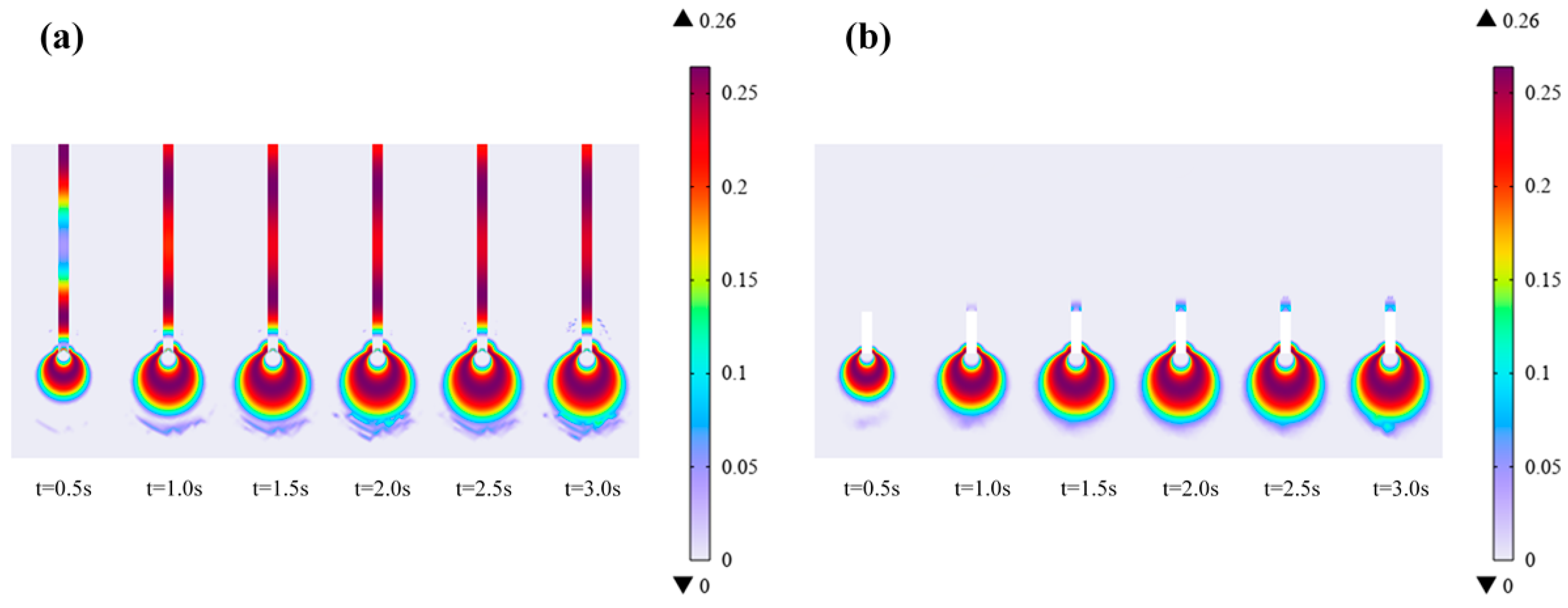
To evaluate the sealing effectiveness of both the traditional cement grouting sealing method and the three-stage sealing method, an analysis of the damage to concrete and surrounding rock during the impact process was conducted. Figure 3 displays damage-cloud maps at selected time intervals during the impact process, specifically at 0.5 s, 1.0 s, 1.5 s, 2.0 s, 2.5 s, and 3.0 s. As observed from Figure 3, both concrete and surrounding rock exhibit a certain degree of damage. The maximum damage value reached is 0.26, with the majority of damage concentrated in the surrounding rock. Over time, the damage area gradually expands, and at t = 2.0 s, the extent of damage no longer increases. The pattern of damage distribution is circular around the impact load, with damage severity gradually decreasing from the center outward. In Figure 3a, the single-layer concrete sealing layer has suffered severe damage. Additionally, due to the fact that the top of the sealing layer is a weak surface structure, the damage at the top of the sealing layer is relatively severe. This indicates that the traditional single-layer concrete sealing method is susceptible to significant damage from transient high-pressure impacts, which could potentially lead to sealing failure. In contrast, Figure 3b demonstrates that the three-stage sealing method results in minimal damage within the concrete inside the sealing layer, with only a portion of the bottom showing damage. The top of the sealing layer remains undamaged, indicating the effective sealing achieved by this method.
Figure 3.
Damage-cloud maps at different times (a) single-layer concrete sealing model (b) three-stage sealing model.
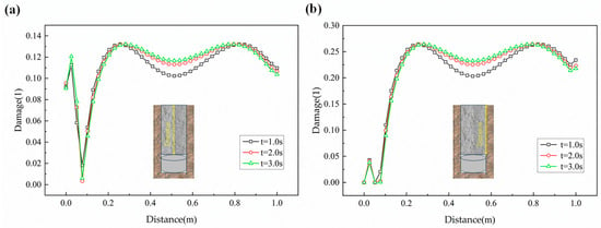
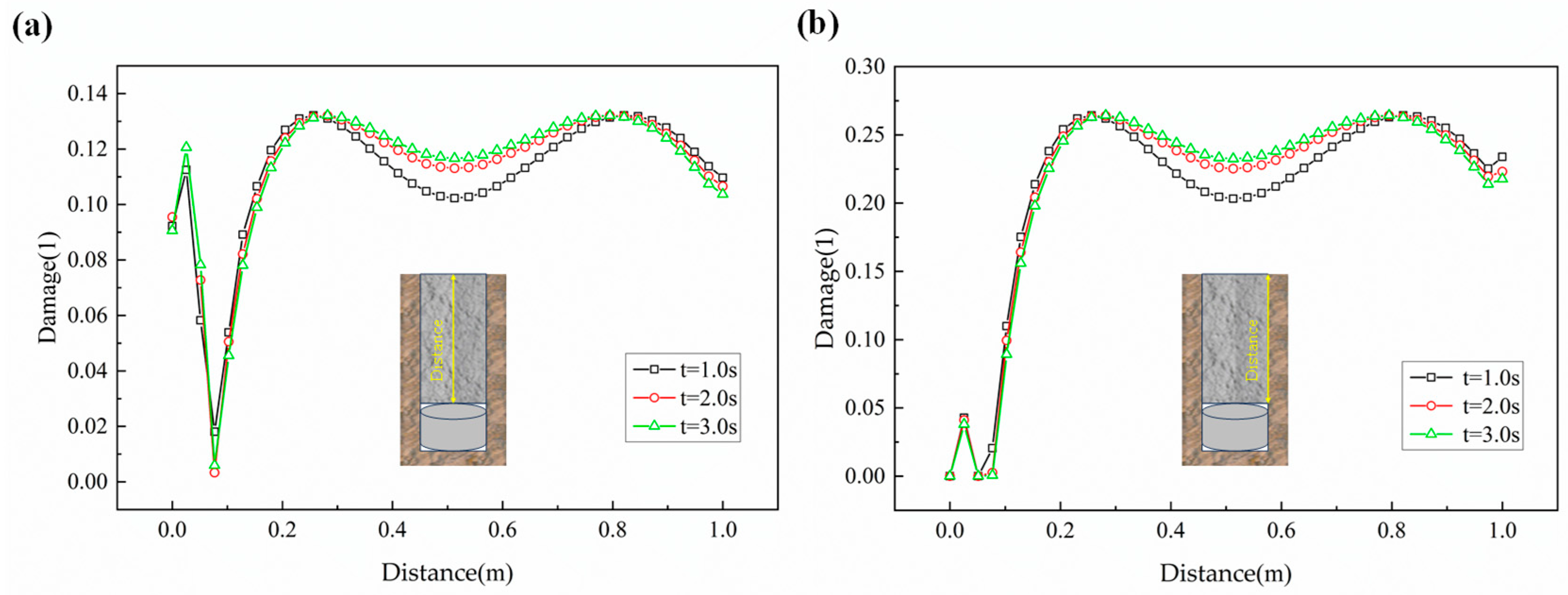
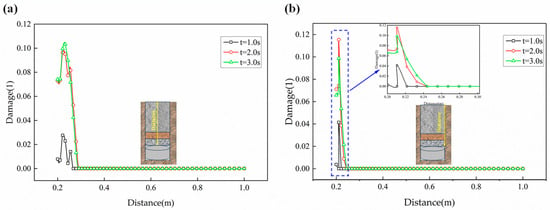
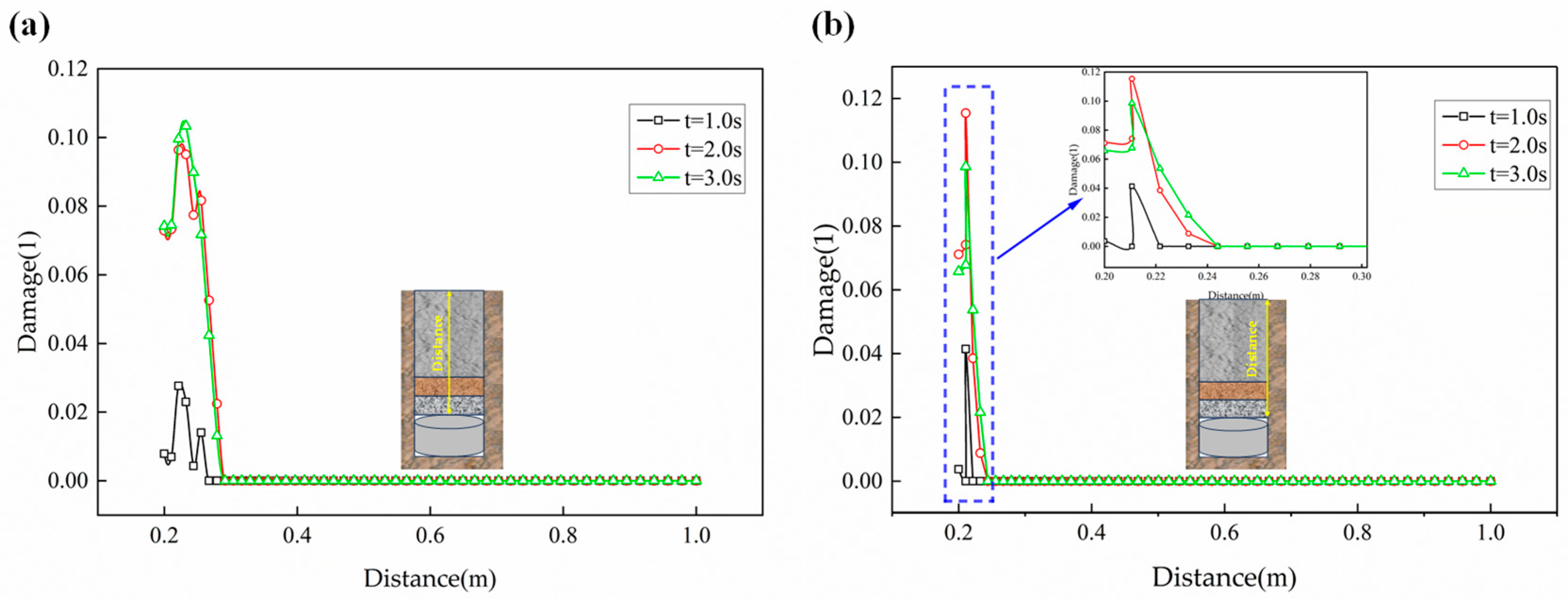
Figure 4 and Figure 5 provide a further analysis of the damage curves at the central axis inside the borehole and on the borehole wall at 1.0 s, 2.0 s, and 3.0 s for both sealing methods. As seen in Figure 4, in the single-layer concrete sealing method, the damage to the concrete section is primarily concentrated in the sealing section located 0.2 m from the borehole bottom and above 0.8 m from the bottom. In comparison, as indicated in Figure 5, the maximum damage in the concrete section of the three-stage sealing method is only approximately 0.12. Additionally, the damage inside the concrete is not as severe as near the concrete boundaries, with a maximum internal damage of about 0.10. This is due to the fact that the concrete bonds with the borehole wall after solidification, and the bonded portion is relatively easier to damage compared to the structural strength of the concrete itself.
Figure 4.
Damage curve of single-layer concrete at different times (a) central axis of the hole (b) hole wall.
Figure 5.
Damage curve of three-stage sealing at different times (a) central axis of the hole (b) hole wall.
3.2. Stress Evolution Analysis
3.2.1. Stress-Reduction Effect of Three-Stage Sealing
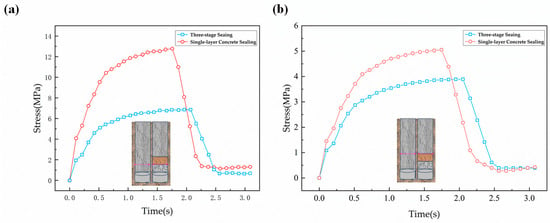
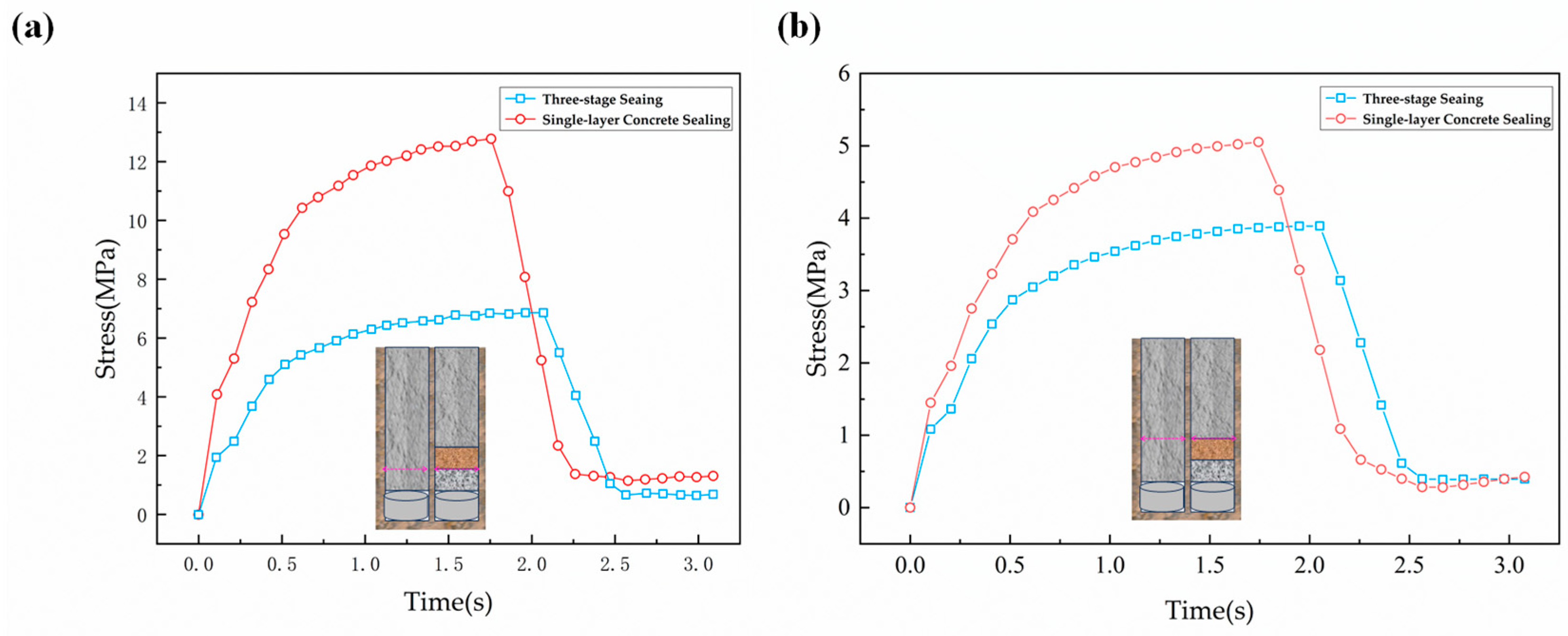
To verify the attenuating effect of the three-stage sealing layer under transient high-pressure impact, the forces at the interfaces between the grave‘l layer and the soil layer, as well as between the soil and concrete, are analyzed during the transient high-pressure impact process. From Figure 6a, it can be observed that when the impact is applied to the bottom of the soil layer, in the three-stage sealing model, the stress at that position continuously increases to a peak of 6.86 MPa, then gradually decreases, and stabilizes at around 0.72 MPa after 2.5 s. In the single-layer concrete sealing, the stress at that position continuously increases to a peak of 12.74 MPa, then decreases to 1.19 MPa, and gradually stabilizes. At the same geometric location, the stress exhibited by the three-stage sealing is consistently lower than that of the single-layer concrete sealing, with a difference in stress peaks of 5.88 MPa. This is because when transient high-pressure gas acts on the three-stage sealing material, it rapidly expands, generating an upward force, compressing the gaps between the stones in the gravel layer, reducing the overall volume, and partially distributing the impact force to deform the entire space, thus achieving a weakening effect. Additionally, the irregular shape of the stacked gravel disperses the impact force in different directions, reducing the impact force in the vertical direction.
Figure 6.
Comparison of single-layer and three-stage sealing forces (a) soil layer bottom (b) concrete bottom.
As shown in Figure 6b, when the impact is applied to the bottom of the concrete layer, the stress variation patterns in the three-stage sealing and single-layer concrete sealing at that position are similar to those observed when the impact is applied to the soil layer. In the three-stage sealing, the stress peak is 3.89 MPa, while in the single-layer concrete sealing, the stress peak is 5.05 MPa, resulting in a difference of 1.16 MPa. At the same geometric location, the stress exhibited by the three-stage sealing is generally lower than that of the single-layer concrete sealing. This indicates that the three-stage sealing method has a more pronounced weakening effect on the impact compared to the single-layer concrete sealing, further confirming the effectiveness of the three-stage sealing process. Unlike the single-layer concrete sealing, the stress at the three-stage sealing location does not linearly decrease in the short term after the impact ends. This suggests that the soil layer, as an elastoplastic material, serves as a cushioning energy absorber. After being impacted, the soil particles in the soil layer shift, slide, break, and reorganize, resulting in plastic deformation of the soil and absorbing a portion of the impact energy. When the impact is applied to the soil itself, the stable soil skeleton exhibits an elastic response to the load, converting a portion of the transient high-pressure energy into the soil’s elastic potential energy, providing a rebound effect, and achieving effective weakening of the impact.
3.2.2. Force Characteristics of Three-Stage Sealing Layer
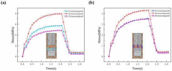
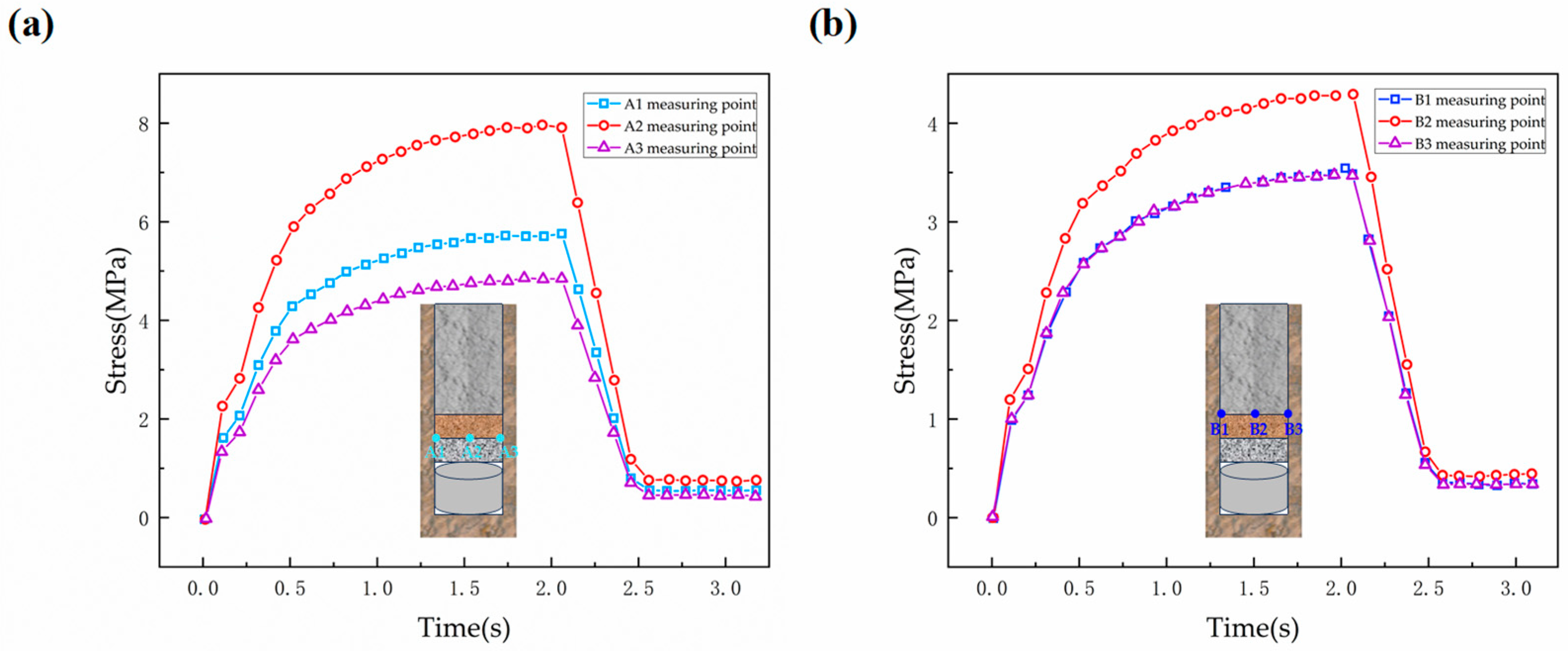
To analyze the stress characteristics of the three-stage sealing layer, the stress characteristics of two different sealing layers, namely, the soil layer and the gravel layer, were analyzed separately (as shown in Figure 7). As observed in Figure 7a, the stress at the bottom of the soil layer exhibits a pattern of initial increase, followed by a decrease, ultimately stabilizing. In the horizontal direction, the stress is highest at the central position and progressively decreases towards both sides. At the point of maximum stress change, the difference between the stress at the central position and the minimum stress at the outermost edge of the sealing material is 2.91 MPa. This behavior is attributed to the static frictional forces generated between the sealing material and the borehole wall during the impact, which weaken the impact on both sides of the material. Figure 7b reveals that at the point of maximum stress change, the difference between the maximum stress and the minimum stress at the outermost edge of the sealing material is 0.77 MPa. After undergoing attenuation through the gravel layer and soil layer, the stress becomes relatively stable. Stress at the central position gradually approaches that at the borehole wall.
Figure 7.
Stress curve of three-stage sealing under different time (a) soil layer bottom (b) concrete bottom. (A1, A2, and A3 represent measurement points at the bottom of the soil layer, with A1 and A3 located at the edges and A2 at the center. B1, B2, and B3 are measurement points at the bottom of the concrete slab, with B1 and B3 located at the edges and B2 at the center).
Figure 6b and Figure 7b illustrate the decisive advantage of the three-stage configuration compared to the traditional single-layer method. Under identical impact conditions, the single-layer concrete experiences a sharp stress concentration at its base, reaching a destructive peak of 13.1 MPa, which exceeds the tensile strength of the material and leads to the severe damage observed in Figure 3. In stark contrast, the bottom concrete in the three-stage method withstands a significantly reduced peak stress of only 3.89 MPa. This 70.3% reduction in peak stress demonstrates that the preceding gravel and soil layers successfully act as a “low-pass filter” for the mechanical load. Furthermore, the stress distribution in the three-stage method is more uniform radially, with stress levels at the center gradually approaching those at the borehole walls, avoiding the “butterfly-shaped” stress concentration often seen in single-layer failures.
3.3. Strain and Displacement Evolution Analysis
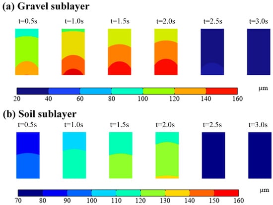
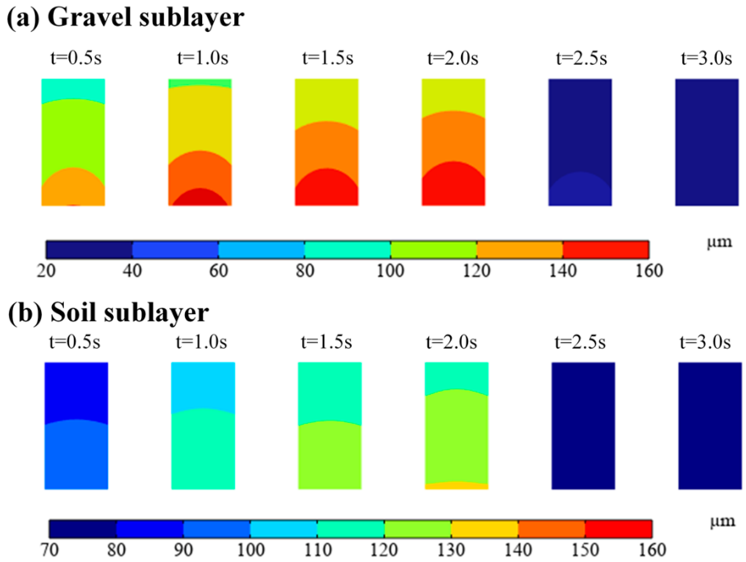
In the three-segment sealing, both the gravel layer and the soil layer are considered as elastoplastic materials with numerous voids within the layers, providing space for material displacement and deformation during the impact process. Figure 8 presents the displacement cloud diagrams for the gravel layer and the soil layer at different time intervals: 0.5 s, 1.0 s, 1.5 s, 2.0 s, 2.5 s, and 3.0 s. From Figure 8, it can be observed that the displacements in both sealing layers gradually increase, reaching their maximum values at 2.0 s. At this point, the displacement in the sealing layers reaches 160 μm, while the soil layer experiences a displacement of 140 μm. As time progresses, a rebound phenomenon occurs. At 3.0 s, the displacements in both sealing layers decrease to below 80 μm. Overall, the displacement in the gravel layer is greater than that in the soil layer.
Figure 8.
Displacement-cloud image of three-stage sealing at different times (a) gravel sublayer (b) soil layer.
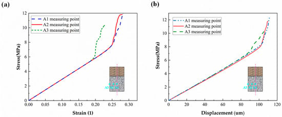
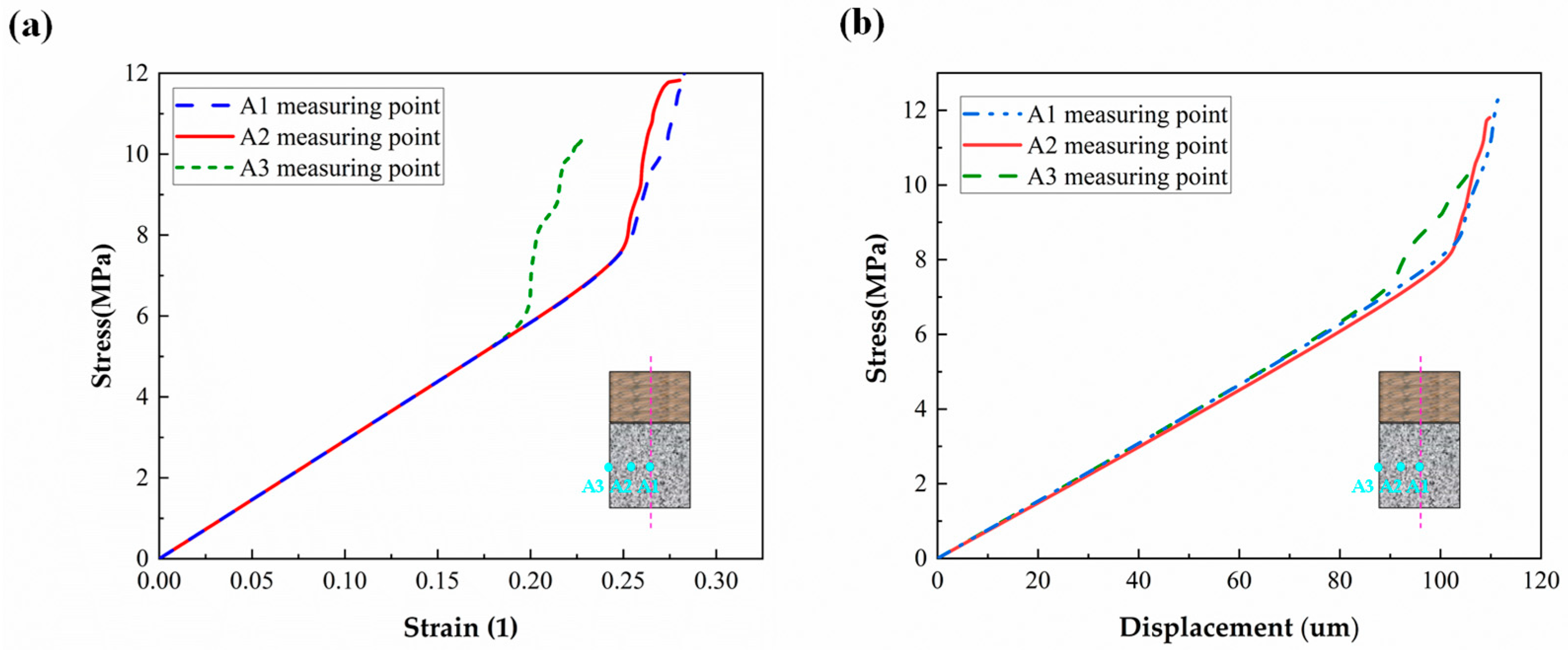
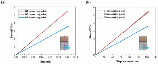
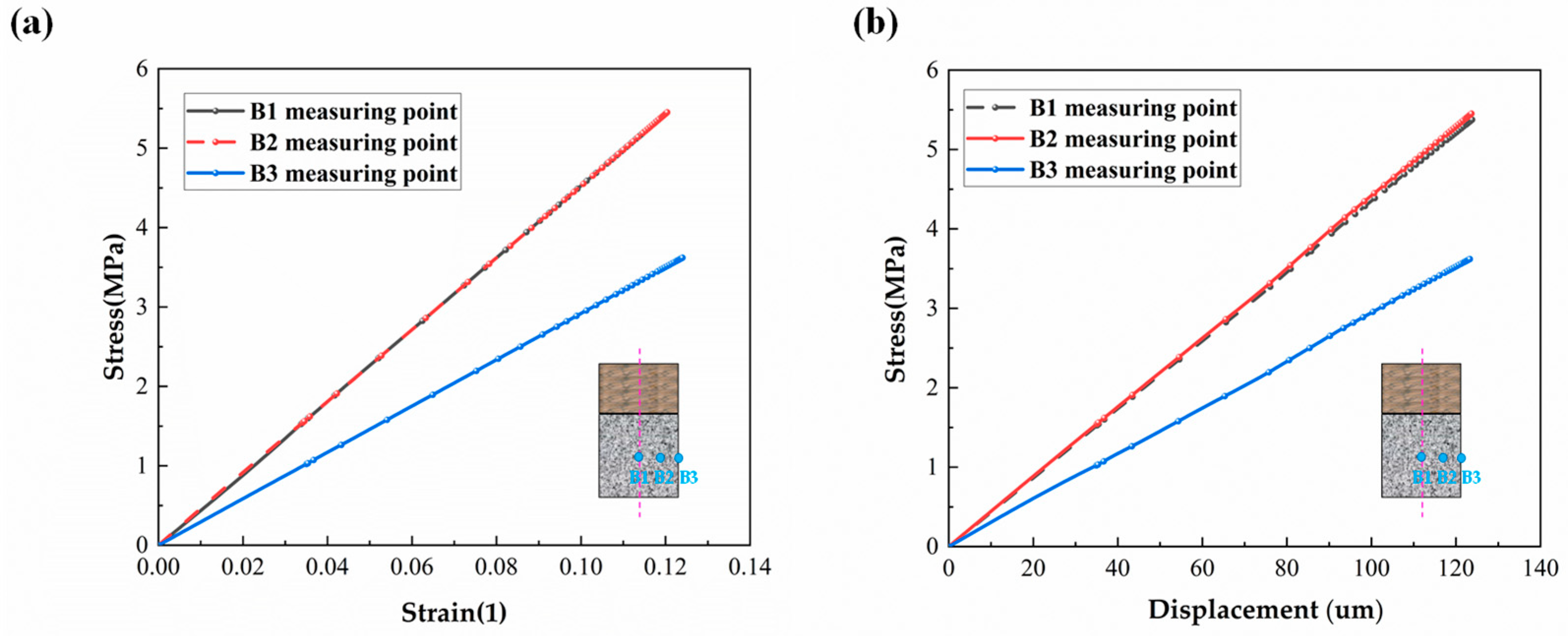
Further, Figure 9 and Figure 10 respectively present the stress–strain and stress–displacement curves for the middle portions of the gravel layer and the soil layer. From Figure 9a, it can be observed that the stress–strain trends at three measurement points initially exhibit linear increases. However, as the load continues to increase, at approximately 6 MPa, the rate of strain increase begins to slow down. Prior to reaching 6 MPa, the stress–strain behavior at all three measurement points is nearly identical, showing linear growth. After the load exceeds 6 MPa, the gravel layer starts to undergo some plastic deformation. In the finite element model, this plastic deformation corresponds to the friction and compression between gravel particles, which positively contributes to energy absorption. Additionally, the central point exhibits the highest strain at 0.27, while the boundary point demonstrates the lowest equivalent strain at 0.23. Strain is a significant indicator for measuring the absorption of elastic potential energy in a material. Consequently, it can be inferred that the central portion of the gravel layer has a greater energy absorption effect compared to the two boundary regions. Figure 9b reveals that until the load reaches 7.5 MPa, displacement linearly increases with stress, indicating a process of compacting the gravel. After the load surpasses 7.5 MPa, the degree of displacement change becomes smaller. This is attributed to the frictional interactions between the compacted gravel particles. In contrast to the gravel layer, the stress–strain relationship of the soil layer does not exhibit a gradual transition like the gravel layer; instead, the soft sealing layer primarily undergoes plastic deformation. From Figure 10a, it can be observed that the stress–strain trends at all three measurement points exhibit linear growth. The maximum strain at all three measurement points exceeds 0.13, and their magnitudes are nearly identical. The stress–strain relationship at measurement points B1 and B2 largely overlaps, indicating that apart from frictional resistance at the boundaries, the deformation in other areas of the soft sealing layer is relatively consistent. This suggests that the capacity to withstand pressure and the energy absorption performance are also consistent. Furthermore, from Figure 10b, it can be observed that under equivalent displacements, measurement points B1 and B2 experience higher stresses. For instance, at a displacement magnitude of 80 μm, the stress at point B1 is 3.79 MPa, while at point B3, the stress is 2.32 MPa. This indicates that the central location has better energy absorption capabilities.
Figure 9.
Stress–strain curve (a) and stress-displacement curve (b) of the three-stage sealed gravel sublayer.
Figure 10.
Stress–strain curve (a) and stress–displacement curve (b) of the three-stage sealed soil layer.
4. The Sealing Mechanism of Three-Stage Sealing
4.1. Energy Analysis
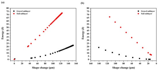
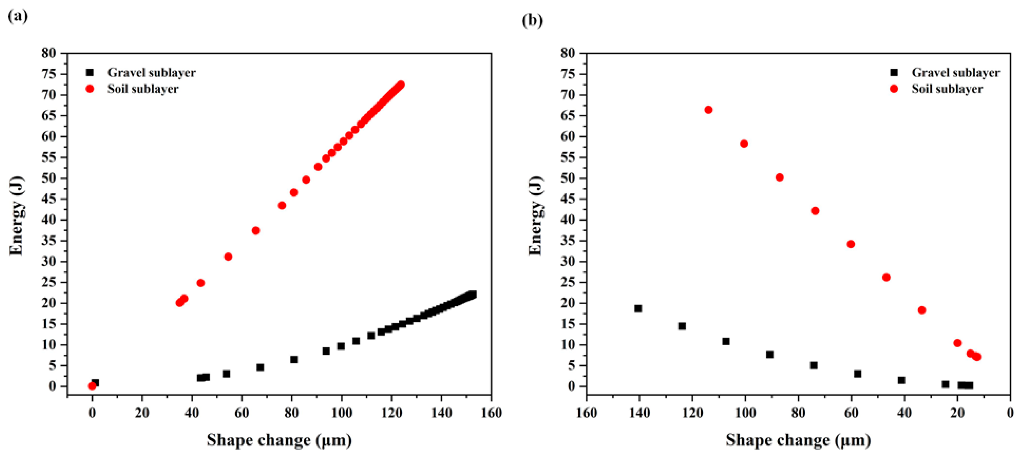
As outlined in Section 3.3, deformations in the gravel layer and soil layer within the three-stage sealing system occur in two stages: the plastic deformation stage and the rebound stage. Figure 11 illustrates the deformation–energy-absorption relationship curves for these two stages. From Figure 11, it is evident that during the plastic deformation stage, both sealing layers (gravel and soil) absorb progressively more energy as deformation increases. In the rebound stage, as the rebound phenomenon occurs, the energy absorption gradually decreases. In contrast, the deformation–energy relationship for the soil layer follows a linear trend. Furthermore, energy-absorption efficiency is a metric used to assess a structure’s ability to absorb energy. To compare the energy-absorption performance of different sealing layers, energy-absorption efficiency can be calculated using Equation (13) for comparative purposes.
Figure 11.
Deformation–energy-absorption relationship of the three-stage sealing layer (a) the plastic deformation stage (b) the bound stage.
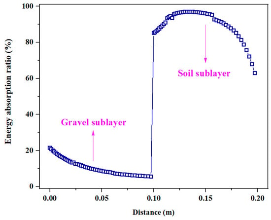
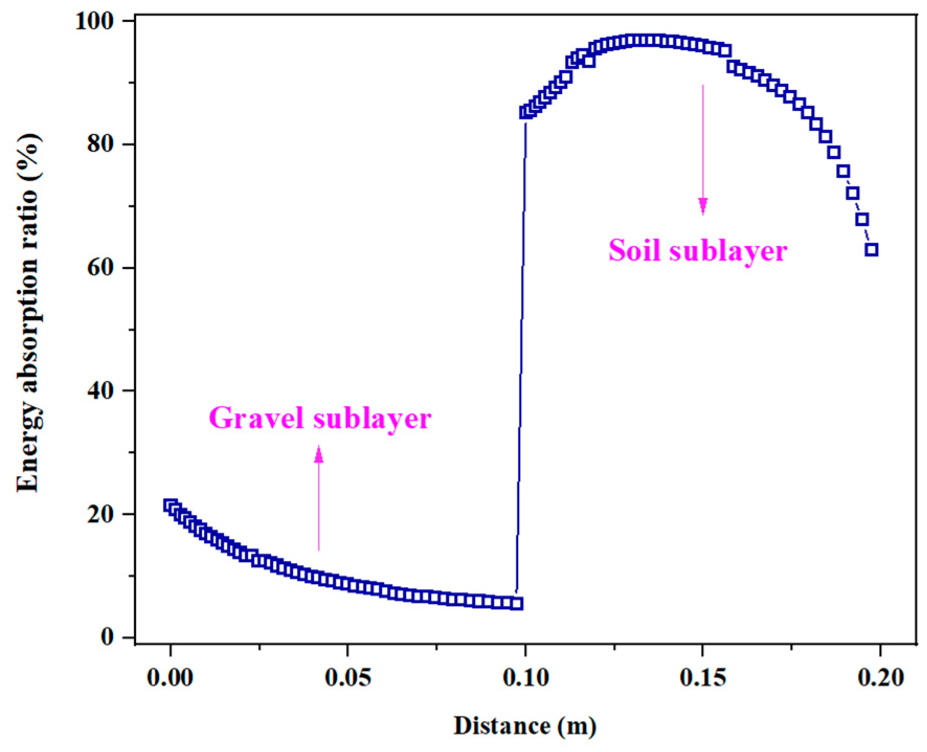
For the gravel layer, the energy-absorption mechanism is dominated by the frictional work generated during the rearrangement and interlocking of discrete particles. However, due to the high stiffness and “bridging effect” of the stone aggregates, the gravel layer tends to transmit stress rather than dissipate it through large deformation, resulting in a relatively lower efficiency. In contrast, for the soil layer, which acts as a porous elastoplastic medium, the efficiency primarily reflects the irreversible work done during pore collapse (volume compaction) and plastic flow. A high efficiency value (approaching 96% as calculated) indicates that the soil layer functions as an ideal “energy sink”, effectively converting the kinetic energy of the transient shock wave into permanent internal deformation, thereby isolating the bottom concrete from the peak impact load.
Figure 12 illustrates the relationship between energy absorption efficiency and position within the three-stage sealing system, specifically for the gravel layer and the soil layer. From Figure 12, it can be observed that the gravel layer has a lower energy absorption capacity compared to the soil layer. As we move further away from the bottom of the borehole, which is farther from the source of the load, the energy-absorption efficiency of both sealing layers decreases. In the case of the gravel layer, this decrease is more pronounced due to the compaction and friction between gravel particles, ultimately resulting in an energy-absorption efficiency of nearly 0. Conversely, the soil layer exhibits relatively high energy-absorption efficiency, reaching up to 96%. This high efficiency suggests that the soil layer is effective at absorbing energy. Notably, the gravel layer, as the bottommost filling material, plays a larger role in dispersing pressure rather than absorbing energy when considering energy efficiency.
Figure 12.
Energy efficiency of three-stage sealing layer.
4.2. Sealing Mechanism
The three-stage sealing method proposed in this paper employs three different materials to seal an uncased borehole. The top layer consists of concrete, while the bottom layer is composed of gravel, both of which are strong structural materials primarily responsible for bearing pressure. The intermediate material in the three-stage sealing method is soil, which has a relatively weaker load-bearing capacity and lower structural strength. Its main function is to provide energy absorption and cushioning. The overall structure of the three-stage sealing method resembles a structure with hard top and bottom layers and a soft middle layer, similar to a laminated structure with energy-absorbing effects [29,30]. The three-stage sealing method weakens the impact by dispersing the pressure through the gravel layer and further dampens the impact through the energy-absorbing soft sealing layer. This structural approach, characterized by “pressure–absorption–pressure”, effectively reduces the impact, thus enhancing the sealing efficiency of the three-stage sealing method.
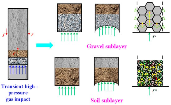
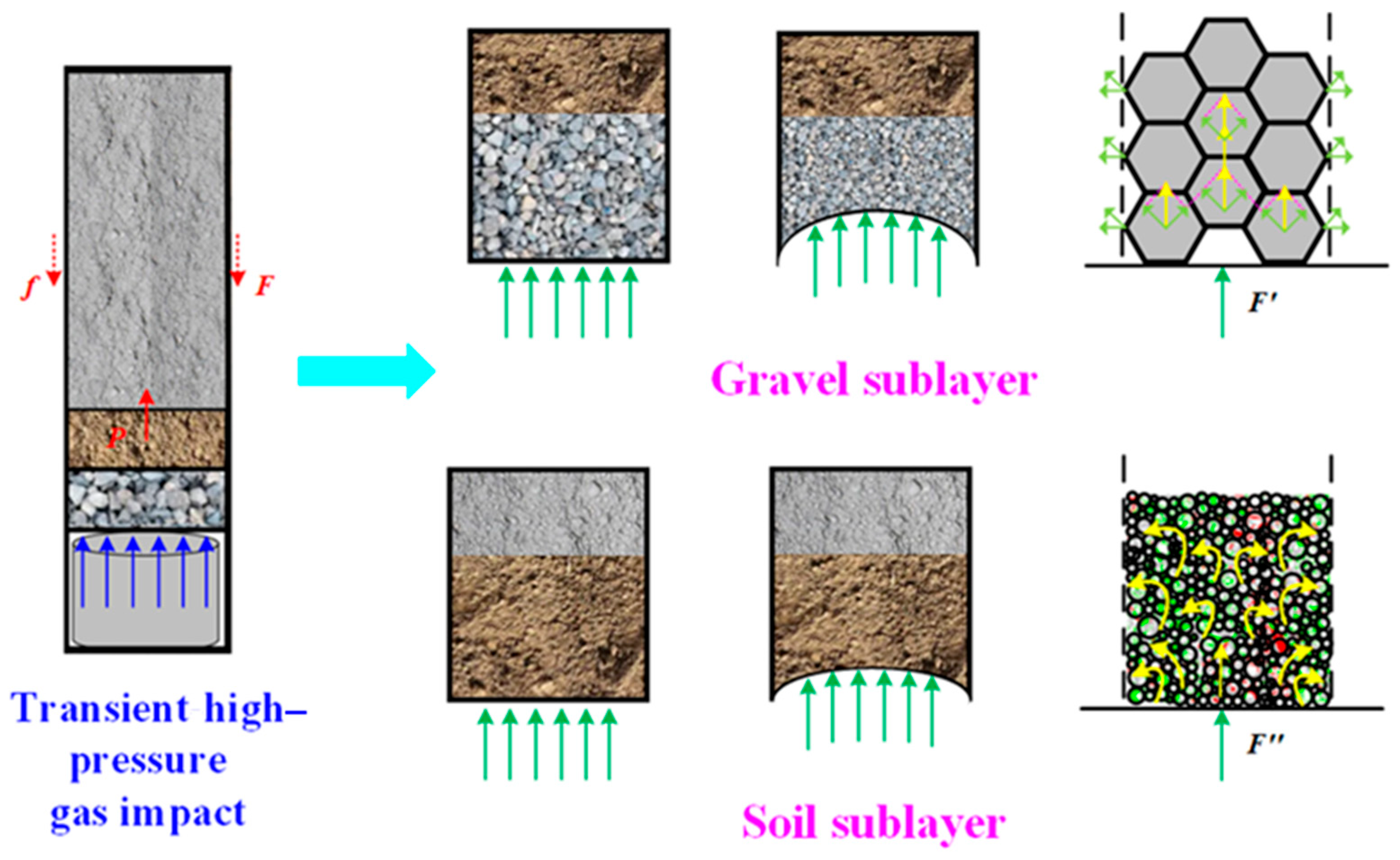
Based on the findings from the various sections discussed, Figure 13 illustrates the sealing mechanism during the process of the three-stage sealing method. In the gravel layer, when subjected to the impact load, the gravel particles reposition themselves and gradually become compacted. To study this, gravel particles are simplified as hexagons. Under the vertical impact, each gravel particle distributes the pressure in three directions: upper left, upper right, and directly upward. Gravel particles near the borehole wall will exert the dispersed pressure on the borehole wall from different angles. In the soil layer, the cohesive bonds between soil particles are disrupted under the influence of the impact load. Additionally, soil is considered as an accumulation of tiny particles. When subjected to the impact load, these soil particles create force chains through contact transmission. The load rapidly propagates within these force chains, allowing the soil layer to absorb more energy compared to the gravel layer.
Figure 13.
Three-stage sealing mechanism.
The three-stage sealing method proposed in this paper employs three different materials to seal an uncased borehole, forming a robust composite structure. Macroscopically, the top layer consists of concrete, while the bottom layer is composed of gravel; both are strong structural materials primarily responsible for bearing pressure and preventing ejection. The intermediate material is soil, which has a relatively weaker load-bearing capacity but high deformability, functioning mainly to provide energy absorption and cushioning. The overall structure resembles a “Hard-Soft-Hard” sandwich system.
To provide a deeper insight into this mechanism, the distinction can be further analyzed from a molecular chemistry perspective. The rigidity and high modulus of the concrete layers originate from the strong covalent and ionic bonds within the Calcium Silicate Hydrate (C-S-H) gel chains formed during cement hydration. While these chemical bonds offer high compressive strength, they inherently possess low ductility, making the material brittle and susceptible to fracture under high-rate transient shock. In contrast, the mechanical response of the intermediate gravel and soil layers relies primarily on weaker physical interactions, such as Van der Waals forces and inter-particle frictional resistance. This fundamental chemical–physical distinction highlights the necessity of the three-stage design: the “physical buffer layers” (gravel and soil) are employed to dissipate high-frequency kinetic energy through macroscopic particle dislocation and rearrangement, thereby protecting the brittle “chemical bonds” of the concrete sealing layer from immediate impact-induced fracture. Through this structural approach of “Pressure Dispersion (Physical)—Energy Absorption (Physical)—Rigid Sealing (Chemical)”, the destructive impact is effectively weakened, ensuring the safety and efficiency of the operation.
While this study provides significant theoretical insights into the three-stage sealing mechanism, certain limitations inherent to the current modeling approach must be acknowledged. Firstly, the numerical simulations treated the intermediate soil layer (representing drill cuttings) as a homogeneous continuous medium. In practical engineering, natural drill cuttings possess significant heterogeneity in particle size and shape, which may lead to localized stress concentrations or gas channeling not captured by the continuum model. Secondly, the influence of groundwater was not explicitly considered. In deep borehole environments, water infiltration can significantly alter the viscosity, plasticity, and friction coefficients of the cushioning layers, potentially affecting their energy absorption capacity.
To address these challenges, future research will focus on two main directions. One is the incorporation of the Discrete Element Method (DEM) to investigate particle-scale interactions, such as the interlocking effect of gravel and the flow behavior of wet cuttings, providing a micro-mechanical validation of the interface behaviors. The other is the optimization of structural design. Future work will explore the optimal length ratios between the gravel, soil, and concrete layers to maximize shock wave attenuation efficiency, aiming to establish a standardized design criterion tailored to varying geological conditions and blast intensities.
5. Conclusions
In this study, using experimental data and finite element analysis, we explored the impact of transient high-pressure gas on sealing methods. We compared the traditional single-layer concrete seal with a novel three-stage method, revealing its advantages. Additionally, we analyzed the mechanical evolution of different sealing layers in the three-stage method and uncovered its sealing mechanism through energy absorption analysis.
The main findings are as follows:
- Under transient high-pressure-gas impact, the top seal in the single-layer concrete method sustains severe damage (max damage: 0.26), posing borehole rupture risks. The three-stage method with soil and gravel shows significantly less damage (most < 0.2), demonstrating effective sealing improvement.
- Under transient high-pressure-gas impact, the three-stage sealing method shows significantly lower stress levels compared to single-layer concrete, with a difference of 5.88 MPa in peak stress values. In the three-stage method, soil layer stress initially rises, then decreases, and stabilizes at the bottom. Stress is highest at the center horizontally and decreases towards the sides. After attenuation through gravel and soil layers, stress stabilizes, approaching that at the borehole wall.
- Under transient high-pressure gas impact, the gravel layer has larger displacement than the soil layer. The central part of the gravel layer absorbs more energy than its boundaries. Unlike the gravel layer, the stress–strain relationship in the soil layer does not show a gradual change. Deformation in the two sealing layers occurs in two stages: plastic deformation and rebound. As deformation increases, energy absorption also grows. During the rebound phase, energy absorption decreases due to rebound. The soil layer’s deformation–energy-absorption relationship is linear.
- In the three-stage sealing method, the top concrete and the bottom gravel are all materials with high structural strength, which mainly play the role of pressure and pressure dispersion. Soil layer mainly plays the role of absorbing energy buffer by resisting and buffering impact through elastoplastic deformation. Through the structure of “pressure—energy absorption—pressure”, the effect of impact is weakened, so as to achieve the purpose of improving the sealing efficiency of the three-stage sealing method.
Author Contributions
Conceptualization, X.D., Z.Y. and T.L.; methodology, X.D. and R.L.; software, Z.Y. and R.L.; validation, R.L., M.L. and H.Y.; formal analysis, Z.Y. and T.L.; investigation, X.D. and T.L.; resources, X.D. and Z.Y.; data curation, X.D.; writing—original draft preparation, M.L., X.D. and Z.Y.; writing—review and editing, M.L. and H.Y.; visualization, R.L. and T.L.; supervision, M.L. and H.Y.; project administration, M.L. and H.Y.; funding acquisition, M.L., H.Y. and R.L. All authors have read and agreed to the published version of the manuscript.
Funding
This research was funded by National Natural Science Foundation of China (Grant No.52274012), and National Natural Science Foundation of China (Grant No.42502225).
Institutional Review Board Statement
Not applicable.
Informed Consent Statement
Not applicable.
Data Availability Statement
The data presented in this study are available upon request from the corresponding author.
Acknowledgments
The authors are grateful to the anonymous reviewers for their constructive comments.
Conflicts of Interest
Author Ming Liu was employed by the company Oil and Gas Technology Research Institute, PetroChina Changqing Oilfield Company. The remaining authors declare that the research was conducted in the absence of any commercial or financial relationships that could be construed as a potential conflict of interest.
References
- Xie, W.; Liu, X.; Zhang, X.; Yang, X.; Zhou, X. A Review of Rock Macro-Indentation: Theories, Experiments, Simulations, and Applications. J. Rock Mech. Geotech. Eng. 2024, 16, 2351–2374. [Google Scholar] [CrossRef] [Scilit]
- Kan, J.L.; Dou, L.M.; Li, H.Y.; Li, J.Z.; Bai, J.Z.; Cao, J.R.; Liu, M.H. Effect of initiation pattern on rock damage and blasting seismic under multi-hole blasting. Geomat. Nat. Hazards Risk 2023, 14, 2192334. [Google Scholar] [CrossRef] [Scilit]
- Li, X.D.; Liu, K.W.; Qiu, T.; Sha, Y.Y.; Yang, J.C.; Song, R.T. Numerical study on fracture control blasting using air-water coupling. Geomech. Geophys. Geo-Energy Geo-Resour. 2023, 9, 29. [Google Scholar] [CrossRef] [Scilit]
- Qin, X.; Zhang, H.; Xu, R.; Zhang, J.; Yuan, C. Experimental Investigation on the Failure Mechanism of Grouted Rock Mass: Mesostructure and Macroscopic Mechanical Behavior. Eng. Fail. Anal. 2024, 161, 108304. [Google Scholar] [CrossRef] [Scilit]
- Mu, W.; Li, L.; Liu, H.; Ren, B.; Chen, J.; Wang, X. An Experimental Study on Fracturing Response and Slurry Flow of High-Pressure Grouting in Fractured Rock. Rock Mech. Rock Eng. 2024, 57, 4533–4558. [Google Scholar] [CrossRef] [Scilit]
- Zhang, Z.X.; Qiao, Y.; Chi, L.Y.; Hou, D.F. Experimental study of rock fragmentation under different stemming conditions in model blasting. Int. J. Rock Mech. Min. Sci. 2021, 143, 104797. [Google Scholar] [CrossRef] [Scilit]
- Chen, T.; Vennes, I.; Mitri, H.S. Investigation into Rock Breakage with Expansive Cement Under Biaxial Confinement. Rock Mech. Rock Eng. 2022, 55, 6263–6277. [Google Scholar] [CrossRef] [Scilit]
- De Silva, V.R.S.; Konietzky, H.; Mearten, H.; Ranjith, P.G.; Kumari, W.G.P. A Hybrid Approach to Rock Pre-conditioning Using Non-explosive Demolition Agents and Hydraulic Stimulation. Rock Mech. Rock Eng. 2023, 56, 7415–7439. [Google Scholar] [CrossRef] [Scilit]
- Sun, X.Y.; Tian, Y.; Yin, W.W.; Wang, H.L. Effect of free water on fatigue performance of concrete subjected to compressive cyclic load. Constr. Build. Mater. 2022, 318, 125995. [Google Scholar] [CrossRef] [Scilit]
- Yu, Z.W.; Li, S.M.; Lu, D.G.; Lu, C.; Liu, J. Failure Mechanism of Single-layer Steel Reticular Domes with Reinforced Concrete Substructure Subjected to Severe Earthquakes. Int. J. Steel Struct. 2016, 16, 1083–1094. [Google Scholar] [CrossRef] [Scilit]
- Chen, Q.Q.; Zhang, Y.H.; Zhao, T.T.; Wang, Z.Y.; Wang, Z.H. Mesoscale Modelling of Concretes Subjected to Triaxial Loadings: Mechanical Properties and Fracture Behaviour. Materials 2021, 14, 1099. [Google Scholar] [CrossRef] [Scilit]
- Zhong, J.H.; Song, C.M.; Xu, J.W.; Cheng, Y.H.; Liu, F. Experimental and numerical simulation study on failure mode transformation law of reinforced concrete beam under impact load. Int. J. Impact Eng. 2023, 179, 104645. [Google Scholar] [CrossRef] [Scilit]
- Wu, L.W.; Huang, D.; Xu, Y.P.; Wang, L. A rate-dependent dynamic damage model in peridynamics for concrete under impact loading. Int. J. Damage Mech. 2020, 29, 1035–1058. [Google Scholar] [CrossRef] [Scilit]
- Hu, X.Y.; Zhang, R.X.; Zhang, B.L.; Zhang, X.H.; Zhang, L.L.; Yang, Y.D.; Yan, F.Z. A Study on the Factors Influencing Coal Fracturing Range Caused by Liquid Carbon Dioxide Phase Transition. Geofluids 2022, 2022, 4754764. [Google Scholar] [CrossRef] [Scilit]
- Liu, J.L.; Li, K.Y.; Du, S.J.; Xiao, S.Q. Experimental Study on Broken Area Evolution Characteristics and Crack Propagation Rules of Water Jet Impacting Concrete with Precracks. J. Perform. Constr. Facil. 2021, 35, 04020130. [Google Scholar] [CrossRef] [Scilit]
- Jin, X.; Rao, P.; Feng, W.; Cui, J. Modelling of Rock Fragmentation under Combined Actions of High Voltage Electropulse and Mechanical Drilling. Geoenergy Sci. Eng. 2026, 256, 214128. [Google Scholar] [CrossRef] [Scilit]
- Li, Y.Z.; Ji, H.J.; Li, G.C.; Hu, S.B.; Liu, X. Effect of supercritical CO2 transient high-pressure fracturing on bituminous coal microstructure. Energy 2023, 282, 128975. [Google Scholar] [CrossRef] [Scilit]
- Han, C.; Sun, C.T. Attenuation of stress wave propagation in periodically layered elastic media. J. Sound Vib. 2001, 243, 747–761. [Google Scholar] [CrossRef] [Scilit]
- Hu, S.; Cai, Y.; Wang, E.; Zhang, L.; Pang, S.; Yan, Z. Mechanism of phase change cracking in high temperature and high pressure CO2 reaction flow. J. China Univ. Min. Technol. 2023, 52, 1203–1215+1240. [Google Scholar] [CrossRef]
- Wang, S.H.; Yang, T.J.; Zhang, Z.; Sun, Z.H. Unsaturated seepage-stress-damage coupling and dynamic analysis of stability on discrete fractured rock slope. Environ. Earth Sci. 2021, 80, 660. [Google Scholar] [CrossRef] [Scilit]
- Corre, G.; Lebee, A.; Sab, K.; Ferradi, M.K.; Cespedes, X. A new higher-order elastoplastic beam model for reinforced concrete. Meccanica 2020, 55, 791–813. [Google Scholar] [CrossRef] [Scilit]
- Saksala, T.; Kouhia, R. A Damage-Plasticity Model for Brittle Materials Based on an Approximation of Rankine Type of Failure Criterion. RakMek 2023, 56, 136–145. [Google Scholar] [CrossRef] [Scilit]
- Wang, J.; Poh, L.H.; Guo, X. Localizing Gradient Damage Model Based on a Decomposition of Elastic Strain Energy Density. Eng. Fract. Mech. 2023, 279, 109032. [Google Scholar] [CrossRef] [Scilit]
- Li, W.L.; Guo, N.; Yang, Z.X. STZ-Clay: A Shear-Transformation-Zone Theory Based Constitutive Model for Clay. Int. J. Plast. 2024, 176, 103958. [Google Scholar] [CrossRef] [Scilit]
- Suebsuk, J.; Horpibulsuk, S.; Liu, M.D. Modified Structured Cam Clay: A generalised critical state model for destructured, naturally structured and artificially structured clays. Comput. Geotech. 2010, 37, 956–968. [Google Scholar] [CrossRef] [Scilit]
- Bacquaert, G.; Raude, S.; Alves-Fernandes, V.; Voldoire, F.; Kondo, D. A Standard Thermodynamic-Based Extension of the Modified Cam-Clay Soil Model and Its Applications. Eur. J. Mech.-A/Solids 2024, 103, 105122. [Google Scholar] [CrossRef] [Scilit]
- Schwertz, M.; Katz, A.; Sorrel, E.; Lemonnier, S.; Barraud, E.; Carradò, A.; D’Astorg, S.; Leriche, A.; Nardin, M.; Vallat, M.F.; et al. Coupled Electro-Thermo-Mechanical Finite Element Modeling of the Spark Plasma Sintering Technique. Metall. Mater. Trans. B-Process Metall. Mater. Process. Sci. 2016, 47, 1263–1273. [Google Scholar] [CrossRef] [Scilit]
- Que, X.C.; Zhu, Z.D.; Niu, Z.H.; Zhu, S.; Wang, L.X. A modified three-dimensional Hoek-Brown criterion for intact rocks and jointed rock masses. Geomech. Geophys. Geo-Energy Geo-Resour. 2023, 9, 7. [Google Scholar] [CrossRef] [Scilit]
- Cui, X.D.; Zhao, L.M.; Wang, Z.H.; Zhao, H.; Fang, D.N. Dynamic response of metallic lattice sandwich structures to impulsive loading. Int. J. Impact Eng. 2012, 43, 1–5. [Google Scholar] [CrossRef] [Scilit]
- Feng, L.J.; Wu, L.Z.; Yu, G.C. An Hourglass truss lattice structure and its mechanical performances. Mater. Des. 2016, 99, 581–591. [Google Scholar] [CrossRef] [Scilit]

Disclaimer/Publisher’s Note: The statements, opinions and data contained in all publications are solely those of the individual author(s) and contributor(s) and not of MDPI and/or the editor(s). MDPI and/or the editor(s) disclaim responsibility for any injury to people or property resulting from any ideas, methods, instructions or products referred to in the content. |
© 2026 by the authors. Licensee MDPI, Basel, Switzerland. This article is an open access article distributed under the terms and conditions of the Creative Commons Attribution (CC BY) license.