


Abstract
This study investigates the use of viscoelastic (VE) material layers, reinforced with steel plates, for the seismic retrofitting of reinforced concrete (RC) frame structures. Conventional retrofitting approaches predominantly aim to enhance structural strength, which can undesirably shift the dynamic characteristics away from their original design intent. In contrast, the present work emphasises energy dissipation as the primary mechanism for improving seismic performance. A practical and efficient material characterisation methodology, based on Dynamic Mechanical Analysis (DMA) test data and subsequent derivation of Prony Series coefficients, is employed for numerical modelling, offering substantial advantages over traditional time-intensive techniques such as stress relaxation experiments. In this study, VE material properties are determined through a combination of DMA testing, curve-fitting approximation, and numerical validation. Once the material behaviour has been characterised, numerical simulations are conducted in both the frequency and time domains to assess the efficacy of the proposed retrofitting scheme in reducing resonant response and lateral displacements. The novelty of the retrofitting technique proposed in this research involves direct application of VE materials in the form of layers backed by metal plates. The results demonstrate that VE layers, combined with steel plates at beam–column joints, enhance the seismic performance of RC frames by increasing damping and reducing vibration amplitudes. The findings highlight the potential of VE-layer-based retrofitting as an effective strategy for controlling seismic responses while avoiding excessive stiffening and associated unfavourable shifts in dynamic response. Furthermore, DMA-based Prony series modelling implemented in Abaqus provides an effective and time-efficient approach for capturing viscoelastic behaviour and can be beneficial at an early stage of research.
1. Introduction
Reinforced concrete (RC) frames remain the predominant structural system for mid-rise residential and commercial buildings in many seismically active regions worldwide. This is particularly true in densely built urban areas of low- and middle-income countries, where RC construction has been favoured for decades due to the apparent simplicity of cast in situ frames and the widespread availability of concrete and reinforcing steel [1,2,3]. However, limited design supervision, poor construction quality, and incomplete implementation of seismic detailing provisions have resulted in a large stock of vulnerable existing RC buildings. Post-earthquake reconnaissance and analytical studies repeatedly document brittle failures of columns and beam–column joints, soft-storey mechanisms, and severe damage to infilled frames in such structures, even under moderate ground motions [4,5,6].
In these contexts, outright demolition and replacement of damaged buildings is often economically and socially infeasible. Instead, owners and public authorities are frequently forced to keep damaged RC buildings in service, sometimes after only rudimentary repairs. A particularly critical subset of this building stock comprises frames in which beam–column joints have experienced cracking, bond deterioration, and loss of confinement during previous earthquakes [4,5,6]. These joints are highly stressed regions where axial forces, bending moments, and shear forces from beams and columns intersect; once damaged, they can become the weakest links of the lateral-load-resisting system. There is a clear need for retrofit solutions that (i) repair or mitigate existing joint damage and (ii) enhance the seismic performance of the frame under future earthquakes, without imposing prohibitive costs or requiring highly specialised workmanship.
Over the past decades, a wide range of local and global retrofit strategies for RC frames has been proposed and implemented. Local schemes include jacketing of columns and joints with reinforced concrete or steel, fibre-reinforced polymer (FRP) wraps, enlarged joint regions, and polymer-modified mortar overlays [7,8,9,10,11,12,13,14,15,16,17,18,19,20]. Global schemes comprise the addition of steel bracing, shear walls, and base isolation systems, as well as more recent “fuse-type” concepts and replaceable links designed to concentrate damage in sacrificial components [21,22,23,24,25,26,27]. These methods have demonstrated their effectiveness in many applications, but they also present important drawbacks in the context considered here. Jacketing and added shear walls may be difficult to implement in occupied, densely built environments; they add mass and stiffness, potentially shifting the dynamic characteristics of the building and leading to higher floor accelerations and unfavourable redistribution of demands. Bracing systems and fuse devices often require substantial steelwork and careful detailing, and they may alter the intended failure mechanism in ways that are not always desirable for non-ductile RC frames [28,29].
In parallel, a substantial body of research has focused on the use of VE dampers and layers as passive energy dissipation devices in building and bridge structures. VE devices have been employed to control wind- and earthquake-induced vibrations of tall buildings, floor systems, and connected structures [30,31]. Comprehensive recent reviews summarise the development of VE dampers, their configurations, materials, and applications in civil engineering structures, including practical design procedures and code provisions [30,32]. Classic and more recent studies have demonstrated that properly designed VE devices can significantly reduce structural responses under seismic and wind actions while preserving the overall stiffness and functionality of the primary structure [31,33,34,35].
Most of this work, however, considers VE dampers as discrete devices placed at storey levels, between adjacent structures, or as part of tuned mass damping systems. Relatively fewer studies have explored the use of thin VE layers embedded directly in RC frame components or joints, particularly in the context of seismic retrofit of existing, damaged buildings. Experimental and numerical investigations have been reported on VE interfaces in beams and on beam–column joints retrofitted by viscoelastic steel-enveloped elements [36,37], as well as on novel VE devices and interlayer connections [24,25]. Nonetheless, applications specifically targeting damaged beam–column joint regions in non-ductile RC frames, representative of structures in densely built, resource-constrained urban areas, remain limited. This motivates the present study, which focuses on simple, constructible interventions at the joint level: thin, lightly compliant VE layers introduced into the beam–column joint region to dissipate energy and reduce local damage concentration during seismic events.
A robust assessment of such a retrofit concept requires an accurate representation of the VE material behaviour over the frequency range relevant for structural vibrations. In structural dynamics, VE materials are commonly modelled using Generalised Maxwell chains (Prony series) or related rheological models, where the complex modulus is represented as a sum of exponential relaxation terms. The appearance of fractional-order derivatives in the constitutive equations of real materials has been recognised since the seminal work of Torvik and Bagley [38] and has led to a rich theoretical framework for linear viscoelasticity based on fractional calculus, as systematically presented by Mainardi and Podlubny [39,40]. Fractional viscoelastic models provide compact descriptions of power-law relaxation and creep and have been successfully applied to soft materials and beams with fractional rheology [14,19,27,29,38].
For civil engineering applications, recent reviews emphasise the role of VE dampers and layers in the dynamic response of frames, floors, and plates, combining experimental, numerical, and analytical approaches [16,30,41]. These works discuss rheological models used in practice, including Generalised Maxwell and fractional Zener models, and survey identification procedures based on Dynamic Mechanical Analysis (DMA) or vibration tests. Identification typically proceeds by fitting the storage and loss moduli, or the complex shear modulus, in the frequency domain, sometimes within uncertainty-aware or nonlinear optimisation frameworks [12,13,14,15,16,17,18,41,42,43,44,45,46]. Examples include the calibration and validation of VE constitutive models for dampers, adhesives, shape-memory polymers, and hybrid polymer composites, with parameters identified over wide ranges of frequencies and temperatures and subsequently implemented in finite element (FE) models [20,21,28,38,42,45,46].
Within this broader context, the present study adopts a pragmatic approach tailored to the retrofit of RC frames with damaged joints. The one-bay, one-storey RC frame considered in this study represents a typical frame segment extracted from a multi-storey RC building. Such sub-assembly modelling is adopted to investigate global dynamic characteristics at the frame level while maintaining computational efficiency. The present numerical investigation should therefore be interpreted as a frame-level case study, aimed at isolating the influence of joint condition and viscoelastic strengthening on the dynamic response, rather than as a full building-scale assessment. A VE polymer is characterised experimentally by DMA over a frequency range representative of structural vibrations; a Generalised Maxwell (Prony series) model is fitted to the complex modulus using standard identification procedures; the resulting rheological model is validated by comparing experimental and numerical hysteresis loops; and the calibrated material model is then implemented in a three-dimensional FE model of a single-storey, single-bay planar (portal) RC frame sub-assembly. Although the FE discretisation is three-dimensional, the response is evaluated for in-plane excitation and in-plane displacements only (out-of-plane vibration is not considered). The frame is analysed in three configurations: (i) undamaged, (ii) damaged without retrofit, and (iii) damaged but retrofitted with VE layers at beam–column joints, under both harmonic excitation and selected earthquake records. The overarching aim is to quantify the potential of thin VE layers to reduce joint demands and global response parameters in a realistic, yet computationally tractable, setting, for buildings representative of densely built, low- to middle-income urban areas. The specific objectives and scope of the research are outlined in the next section.
2. Objectives of the Research
The primary aim of this research is to evaluate the potential of viscoelastic (VE) layers as a retrofitting solution for enhancing the dynamic resistance of reinforced concrete (RC) frame structures, with a specific focus on beam–column joints where stress concentrations and damage typically initiate under dynamic loading. The study concentrates on existing RC frames representative of seismically exposed, densely built urban areas, in which joint damage and deterioration may significantly reduce the structural reliability and safety margin.
To achieve this aim, the research first characterises the mechanical behaviour of the selected VE material by means of Dynamic Mechanical Analysis (DMA), capturing its frequency-dependent response in terms of storage and loss moduli. The experimentally obtained data are then processed to identify the parameters of a Generalised Maxwell model expressed in Prony series form, which serves as the basis for constitutive modelling in the numerical analyses. The rheological model derived from the DMA data is subsequently verified by comparing finite element (FE) simulations with experimental force–displacement hysteresis responses, ensuring that the adopted Prony representation accurately reproduces the dissipative behaviour of the VE material.
The identified Prony series parameters are implemented in finite element simulations conducted in Abaqus to model the dynamic response of an RC frame in three configurations: an undamaged frame with monolithic beam–column joints, a damaged frame with degraded joint stiffness, and a retrofitted frame incorporating VE layers at the beam–column joints. The numerical analyses are performed in both the time and frequency domains in order to evaluate the effectiveness of the VE layers in reducing lateral displacements, attenuating resonant response, and modifying key dynamic characteristics such as natural frequencies and modal amplitudes.
Despite the growing interest in the use of viscoelastic materials for structural retrofitting, the literature still lacks comprehensive studies that directly quantify their effectiveness when VE layers are applied specifically at the beam–column joints of RC frames under dynamic loading. This study addresses that gap by integrating experimentally derived VE material properties into a validated finite element framework and by systematically comparing undamaged, damaged, and retrofitted RC frames in both time- and frequency-domain analyses. In doing so, the research provides new insights into how effectively VE layers can contribute to vibration mitigation, displacement reduction, and the improvement of the dynamic performance of critical joint regions, thereby offering a more rigorous understanding of their practical retrofitting potential.
3. Research Methodology
This study employs a combined experimental–numerical methodology to assess the effectiveness of viscoelastic (VE) layers in improving the dynamic performance of reinforced concrete (RC) frame structures. In line with the objectives outlined in Section 2, the workflow is organised into three main phases: (i) material characterisation by Dynamic Mechanical Analysis (DMA), (ii) constitutive modelling of the VE material using a Generalised Maxwell (Prony series) model, and (iii) structural simulation of RC frames with and without VE retrofitting.
In the first phase, DMA is carried out on a laboratory specimen composed of four VE layers bonded between aluminium plates. Under sinusoidal loading over a range of excitation frequencies representative of structural vibrations, the force–displacement response is recorded and processed to obtain the storage modulus G′(ω) and loss modulus G″(ω). These frequency-dependent moduli characterise the elastic and dissipative components of the VE response and form the experimental basis for subsequent model identification.
In the second phase, the VE material behaviour is represented using a Generalised Maxwell model expressed in Prony series form, compatible with standard finite element (FE) implementations. The experimental storage and loss moduli are post-processed in MATLAB R2024b to identify the Prony parameters in the frequency domain. Both G′(ω) and G″(ω) are normalised to improve numerical conditioning, and a two-term Prony model is adopted as a compromise between accuracy and parsimony. Nonlinear least-squares optimisation (MATLAB’s lsqcurvefit routine) is used to simultaneously fit the storage and loss moduli by adjusting the relaxation strengths and relaxation times of the Maxwell elements within prescribed bounds. The quality of the fit is assessed using the root mean square error (RMSE) for both moduli, and the fitted curves are compared visually with the experimental data to verify that the main stiffness and damping trends are adequately reproduced.
Model validation is carried out by reproducing the DMA test in Abaqus/CAE 2025 and comparing numerical force–displacement hysteresis loops with their experimental counterparts. Agreement between the simulation and experiment confirms that the adopted rheological model captures the dissipative behaviour of the VE material with sufficient accuracy for use in frame-level analyses.
Once the VE behaviour has been characterised and modelled, the identified material parameters are implemented into an FE framework using Abaqus. The viscoelastic properties are defined in the time domain via the Prony series formulation, which enables simulation of stress relaxation and hysteresis behaviour without requiring direct use of experimental time histories. This strategy allows a computationally efficient FE representation of the VE material based solely on a compact set of identified parameters, rather than on full experimental response curves.
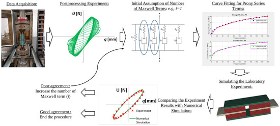
A schematic workflow illustrating the major steps of the procedure followed in this study for the material characterisation is shown in Figure 1 below.
Figure 1.
Workflow for obtaining Prony series terms and validation using DMA data.
The workflow establishes a closed-loop link between experimental characterisation and numerical modelling. The experimentally obtained force–displacement hysteresis is post-processed to derive frequency-dependent viscoelastic properties, which are then represented using a Prony series formulation based on an assumed number of Maxwell terms. The fitted storage and loss moduli are subsequently implemented in the numerical model, and the simulated response is directly compared with laboratory results. If discrepancies are observed, the Prony series complexity is iteratively refined by increasing the number of terms used in the material model.
In the structural phase, three RC frame configurations are modelled independently, taking into account the degrees of freedom at the beam–column joints: (i) an undamaged frame with monolithic joints, (ii) a damaged frame exhibiting stiffness degradation and cracking in the joint regions, and (iii) a retrofitted frame incorporating VE layers at critical beam–column connections, defined by the Prony series parameters obtained from the DMA-based identification. Time-domain simulations are performed by applying recorded earthquake ground motion to quantify the transient displacement response. In parallel, harmonic loading is used in the frequency domain to investigate changes in dynamic characteristics such as natural frequencies, mode shapes, and frequency response functions. Overall, this multi-stage methodology provides a consistent framework to evaluate the feasibility, accuracy, and structural benefits of VE layer–based retrofitting systems for RC frames.
3.1. Experimental Setup
Dynamic Mechanical Analysis (DMA) was carried out using an ElectroPuls E10000 All-Electric Dynamic Test Instrument (Instron, Norwood, MA, USA) equipped with a servo-hydraulic actuator capable of applying precisely controlled cyclic loads over a wide frequency range. The system allows accurate measurement of both force and displacement, enabling a reliable determination of viscoelastic material properties under harmonic excitation.
The test specimen was constructed with known geometrical dimensions, consisting of four layers of viscoelastic (VE) material bonded between aluminium plates in a symmetrical configuration designed to undergo predominantly shear deformation during testing. The layer thicknesses and bonded surface areas were predefined during specimen fabrication and measured prior to testing, providing accurate geometric input data for the subsequent evaluation of mechanical behaviour and for the conversion of the measured force–displacement histories into shear stresses and strains.
The DMA tests were conducted under controlled sinusoidal displacement loading to record the force–displacement response of the specimen over a range of excitation frequencies. The applied angular frequencies were 1 rad/s, 5 rad/s, and subsequently from 10 rad/s to 200 rad/s in increments of 10 rad/s. This excitation range is relevant for the intended application and covers the dynamic response of frame sub-assemblies and structural components; the associated frequencies may exceed typical fundamental building frequencies but remain appropriate for joint-level and local frame vibration assessment. Furthermore, the extended frequency range was selected to improve the robustness of the viscoelastic material parameter identification for numerical analysis. Including higher frequencies enables better conditioning of the curve-fitting process used to derive the Prony series coefficients by constraining short-term viscoelastic response. All tests were performed at room temperature (approximately 24 °C), without any additional heat treatment or thermal conditioning of the shear specimen. The ambient laboratory temperature was maintained constant throughout the tests, and no temperature-dependent effects were intentionally introduced. Accordingly, the identified Prony series parameters should be interpreted as valid for approximately 24 °C. Extending the model to a broader service-temperature range would require DMA at multiple temperatures and, if needed, time–temperature superposition.
The DMA tests were carried out using an Instron testing machine, and the testing protocol was controlled via the WaveMatrix software in a displacement-controlled harmonic loading mode. The viscoelastic specimen was subjected to cyclic loading with an imposed deformation amplitude of ±0.1 mm. The linear-viscoelastic assumption is therefore tied to the small-strain regime used in the DMA programme. If larger shear strains are expected in practice, amplitude-dependent (nonlinear) viscoelasticity should be considered. Displacement control was adopted to prevent specimen damage and to ensure stable testing conditions. The selected deformation level was sufficiently small to maintain the material response within the linear viscoelastic range. For each excitation frequency, the response was monitored until steady-state conditions were reached, after which the corresponding hysteresis loops were extracted.
Repeatability of the measurements was verified by observing that stable hysteresis loops were obtained after a few initial conditioning cycles and that differences between subsequent cycles were negligible, indicating a consistent and repeatable material response. From the steady-state hysteresis loops, the storage modulus G′(ω) and loss modulus G″(ω) were derived, characterising the elastic and dissipative components of the material behaviour over the investigated frequency range.
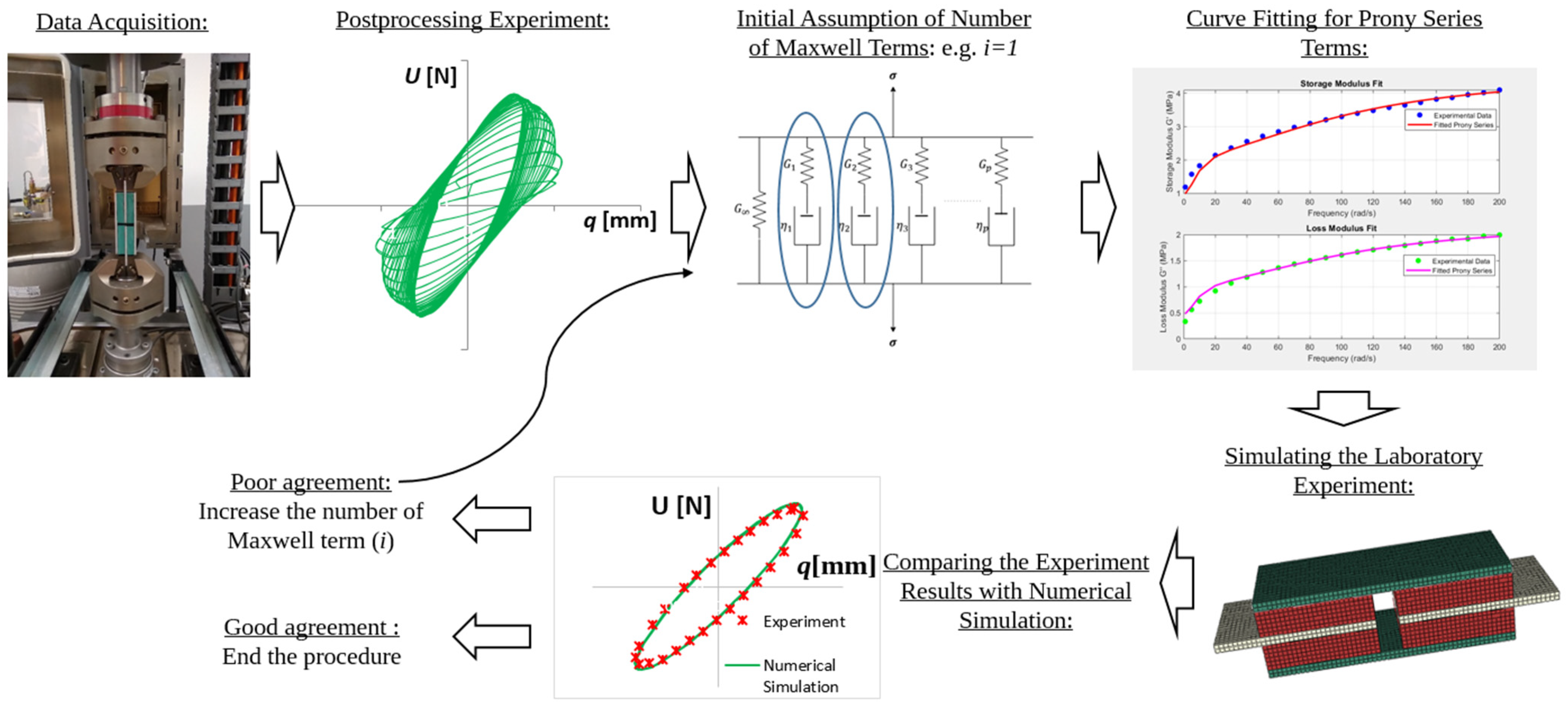
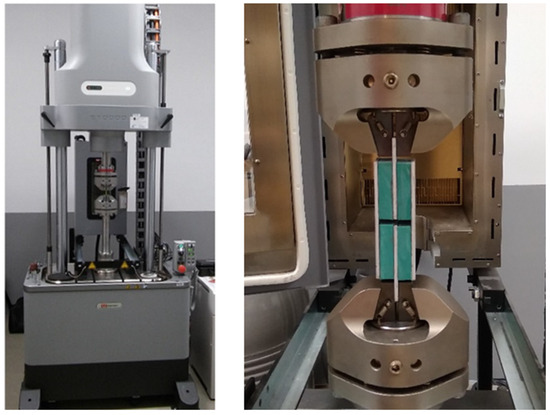
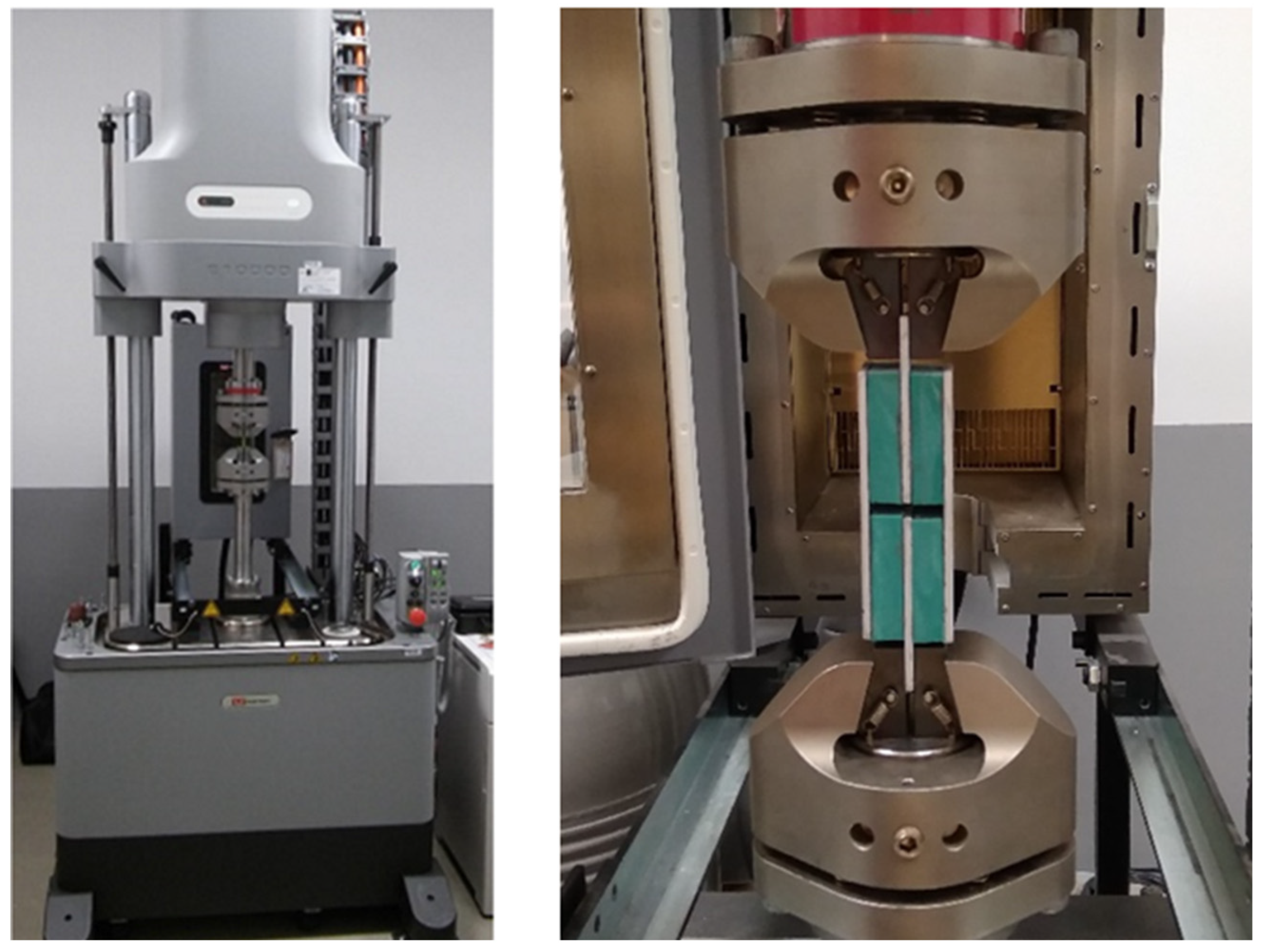
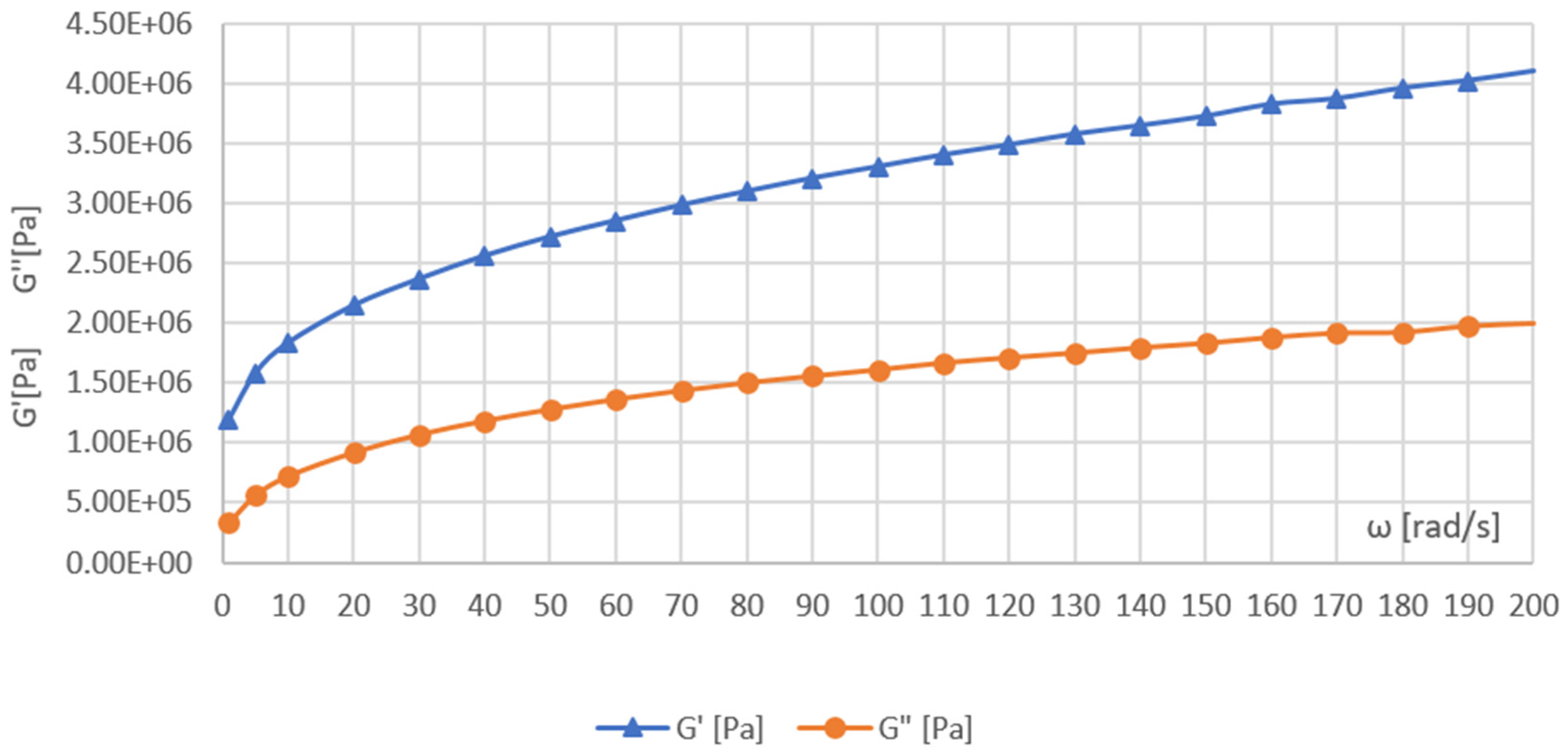
These experimentally obtained moduli form the basis for frequency-domain fitting and derivation of the Prony series parameters used in the subsequent material modelling. Figure 2 shows the DMA experimental setup, where an Instron 10000 testing machine applies cyclic loading to a specimen composed of four VE layers bonded between aluminium plates. This configuration allows controlled shear deformation and enables accurate measurement of the force–displacement response across the selected frequency range. Figure 3 presents the corresponding storage (G′) and loss (G″) moduli of the VE specimen as functions of frequency, providing the reference curves for the identification of the Generalised Maxwell (Prony series) model discussed in Section 3.2.
Figure 2.
Instron testing machine and VE specimen during testing.
Figure 3.
Frequency-dependent storage (G′) and loss (G″) moduli of the viscoelastic (VE) specimen obtained from DMA testing.
3.2. Material Modelling
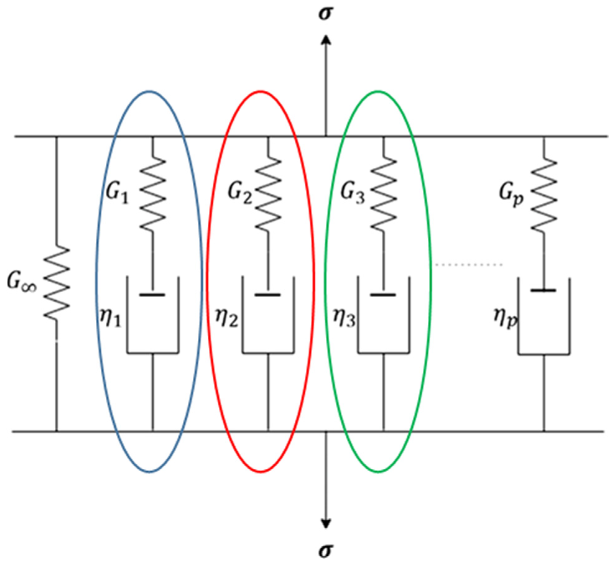
The viscoelastic behaviour of the material used in this study is represented by a Generalised Maxwell model, a commonly adopted rheological model for linear viscoelasticity. The model consists of a set of Maxwell elements, each composed of a spring and a dashpot connected in series, assembled in parallel with an equilibrium spring. The overall stress–strain response is therefore governed by the combined action of an instantaneous elastic contribution and time-dependent viscous effects, allowing the material to reproduce both stress relaxation and hysteresis under cyclic loading. The rheological structure of the Generalised Maxwell model adopted in this study is illustrated schematically in Figure 4.
Figure 4.
Schematic representation of the Generalised Maxwell model used to describe the viscoelastic behaviour of the material.
In the Generalised Maxwell model, the total stress response is obtained by superimposing the contributions of all Maxwell branches and the equilibrium spring. Each Maxwell element is characterised by a relaxation shear modulus contribution and a relaxation time , which control the rate at which stress in that branch decays under constant strain. Using several branches with different relaxation times allows the model to reproduce a broad spectrum of viscoelastic responses across the relevant loading frequencies. In the time domain, the shear relaxation modulus G(t) can therefore be written in the Prony series form
where is the long-term (equilibrium) shear modulus, and are the relaxation modulus and relaxation time of the i-th Maxwell element, respectively, and N is the total number of Maxwell branches.
For frequency-domain analysis, the complex shear modulus is derived from the Fourier transform of the relaxation modulus and can be written as
The relationship between the time-domain relaxation modulus and the frequency-domain complex modulus is thus established through the Fourier transform, which allows the material behaviour to be characterised over different frequency ranges. The standard integral form of the complex modulus is
To take into account the non-zero equilibrium modulus, (which represents the long-term, purely elastic response), the Fourier transform integral is modified by adding and subtracting ,
To obtain the frequency-domain model, the modified term () is isolated and substituted back into the Fourier integral in Equation (4).
Substituting this result into the expression for complex shear modulus yields
By recognising that
By separating complex shear modulus into its real part (storage modulus, and imaginary part (loss modulus, , the frequency-domain Prony series model is obtained
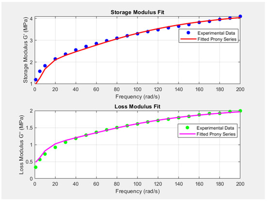
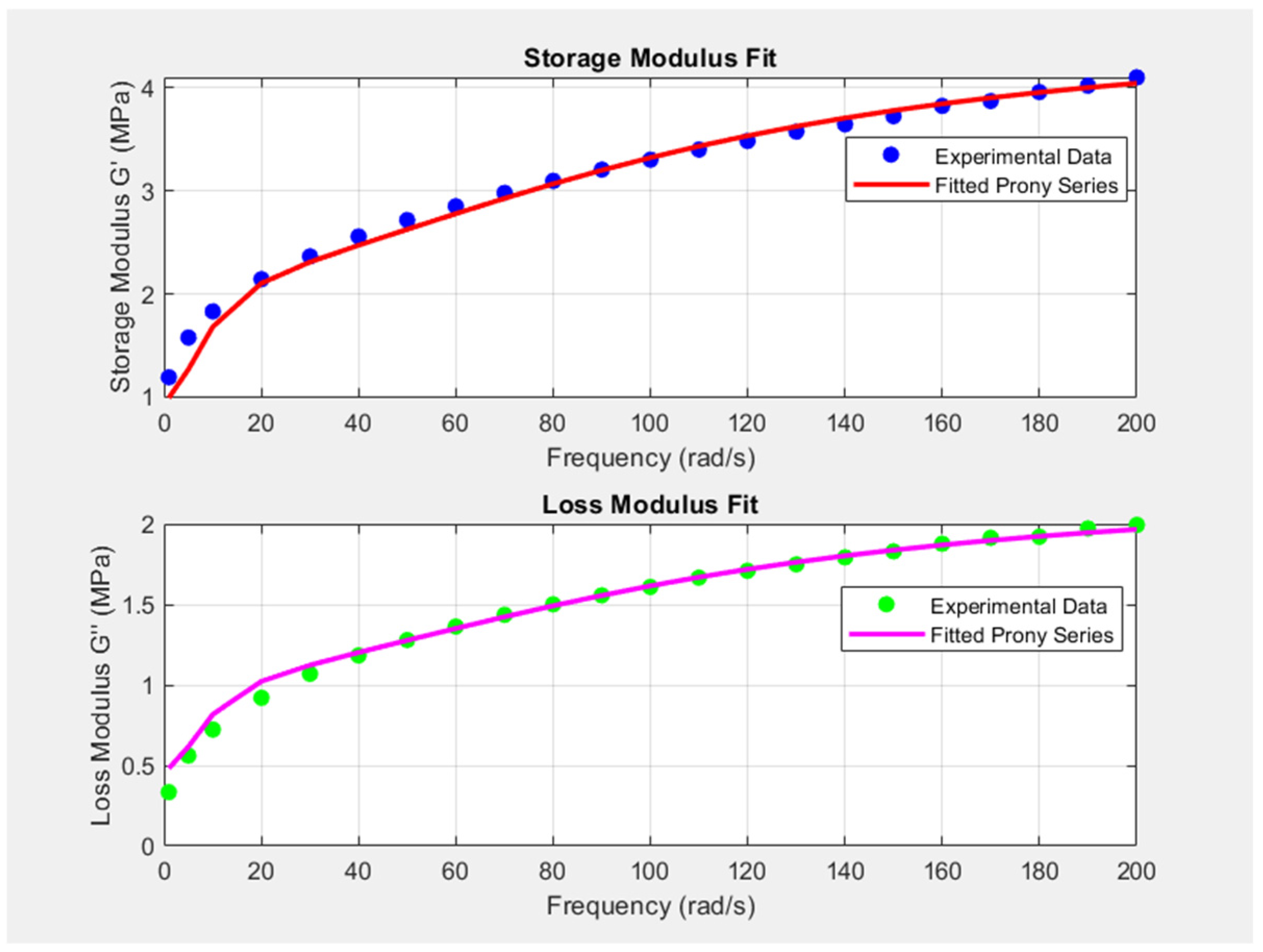
In this study, the Prony series parameters defining the Generalised Maxwell model were identified through MATLAB-based fitting of the experimental DMA results. The storage and loss moduli and obtained from the laboratory tests were fitted simultaneously to the frequency-domain Prony series model given by Equations (8) and (9). Nonlinear least-squares optimisation (MATLAB’s lsqcurvefit routine) was used to minimise the difference between the experimental and theoretical values by adjusting the relaxation moduli and the corresponding relaxation times of the Maxwell elements within prescribed bounds. The resulting fitted curves closely reproduce the experimental trends for both the storage and loss moduli, as illustrated in Figure 5, and provide a compact rheological description suitable for implementation in finite element analyses in Abaqus.
Figure 5.
Experimental storage and loss moduli and fitted Prony series curves.
3.3. Numerical Modelling
All numerical simulations in this study were carried out using the finite element software Abaqus/CAE 2025. The analyses were designed to fulfil two main objectives.
First, a detailed finite element (FE) model of the Dynamic Mechanical Analysis (DMA) specimen was developed to reproduce the shear deformation test performed on the Instron 10000 machine. In this model, the viscoelastic (VE) material was defined by the Prony series parameters identified from the DMA data, as described in Section 3.2. The purpose of this simulation was to assess whether the adopted number of Prony terms is sufficient to capture the dynamic behaviour of the VE layer. For this reason, the force–displacement hysteresis loops obtained numerically were compared directly with the experimental DMA curves. The final model employed two Maxwell terms. The root mean square error (RMSE) values for the storage and loss moduli were evaluated alongside comparisons of experimental and numerical hysteresis curves. Adding more terms improved the numerical fit but caused the force–displacement hysteresis to show signs of overfitting relative to the experimental response. Since hysteresis behaviour reflects the combined effect of the storage and loss moduli, a two-term Prony series was considered sufficient to capture the essential viscoelastic response without introducing unnecessary model complexity. The Prony series parameters for the two Maxwell elements are summarised in Table 1.
Table 1.
Prony series coefficients optimised from curve fitting.
In Table 1, Gi and τi denote the relaxation shear modulus contributions and relaxation times of the Maxwell branches, respectively. The dimensionless coefficients gi correspond to the normalised shear Prony terms used in Abaqus (typically gi = Gi/G0, where G0 is the instantaneous shear modulus). Bulk viscoelasticity was neglected in this study (ki = 0), assuming a time-independent volumetric response. This assumption is commonly adopted for polymer-based viscoelastic materials, as their time-dependent behaviour is governed mainly by shear deformation, while the bulk modulus exhibits negligible time dependence.
To evaluate the quality of the viscoelastic parameter identification, the fitted storage and loss moduli were compared with the experimental dynamic modulus data using the RMSE. The fitted storage modulus exhibits an RMSE of 0.09 MPa, indicating a good representation of the elastic response. The loss modulus shows a higher RMSE of 0.50 MPa, which is in line with previous studies that note Prony series fits often match storage modulus more closely than loss modulus because the loss values are much smaller and have higher experimental uncertainty. It is well established that for many solids, loss modulus is typically significantly smaller than storage modulus, making it more prone to relative error when fitted simultaneously with the dominant storage modulus [47,48]. The higher RMSE for the loss modulus reflects its smaller magnitude and higher experimental uncertainty compared with the storage modulus; however, when the experiment is combined with numerical simulations to generate force–displacement curves, comparison between them can provide insight into whether this higher RMSE leads to over- or underestimation of energy dissipation.
Once satisfactory agreement between experiment and simulation had been achieved, the same material model was used in frame-level analyses. In the second stage, three-dimensional FE models of one-bay, one-storey reinforced concrete (RC) frames were constructed to evaluate the effectiveness of the proposed retrofitting scheme. The frames were analysed in three configurations: an undamaged frame with monolithic joints (FR.01), a damaged frame with degraded joint stiffness (FR.02), and a retrofitted frame incorporating VE layers at the beam–column joints (FR.03). For each configuration, both frequency-domain and time-domain simulations were performed to quantify changes in dynamic characteristics and displacement demands.
3.3.1. Validation of Simulation Results with Experiment
To validate the VE material model implemented via the Prony series parameters, the DMA test setup was reproduced in Abaqus. The VE behaviour in this simulation was defined using the Prony coefficients obtained from the frequency-domain fitting of the experimental storage and loss moduli. The numerical model was used to generate force–displacement hysteresis loops, which were then compared with the corresponding curves from the DMA test.
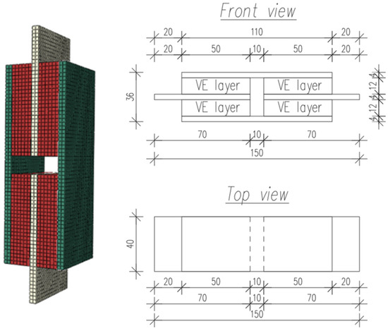
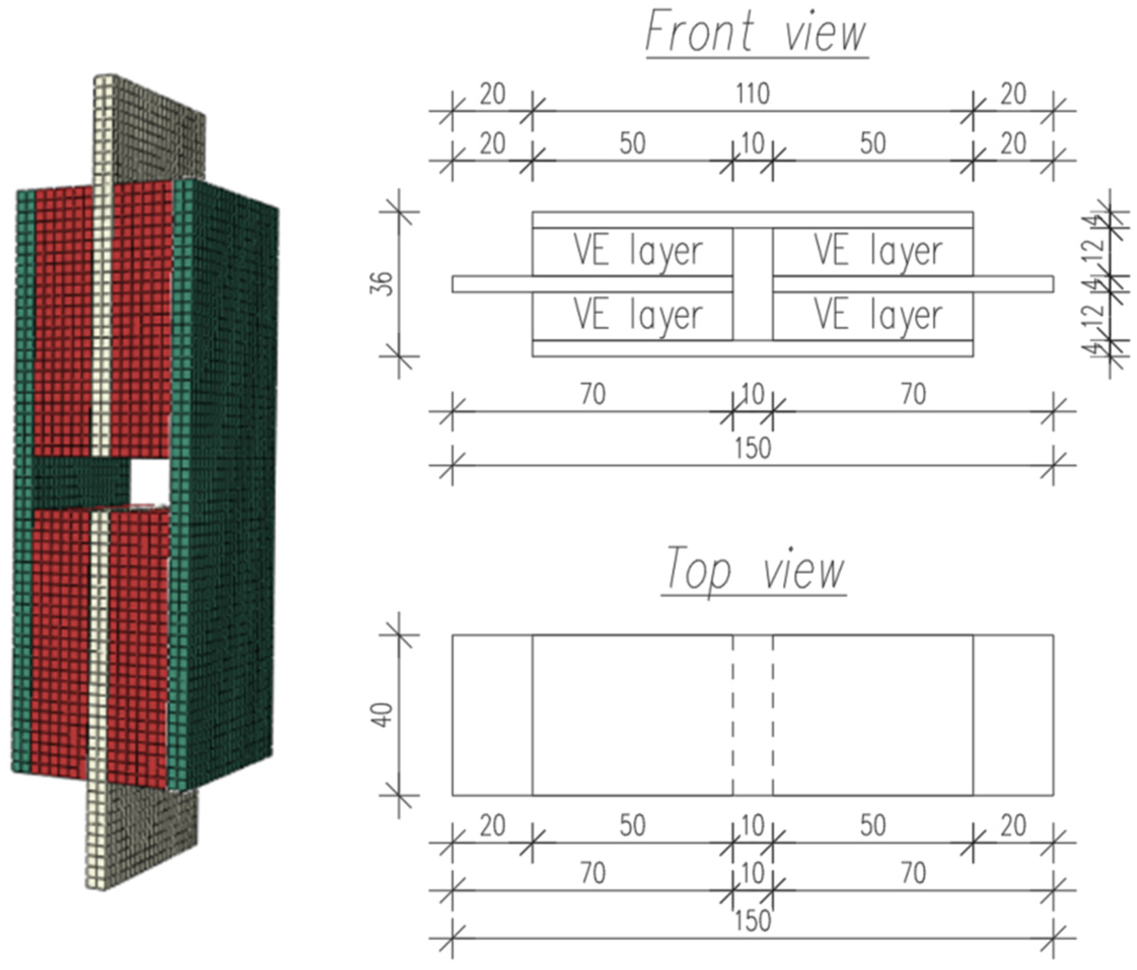
Figure 6 shows a three-dimensional FE model of the shear specimen in Abaqus, along with the front and top views of the test sample, with dimensions indicated in mm.
Figure 6.
FE model of the shear specimen and front/top views of the DMA sample (dimensions in mm).
The model consists of aluminium plates separated by an interlayer of VE material. The aluminium components were modelled as linear elastic solids, while the VE interlayer was represented using the time-domain Prony series formulation. Multiple instances of the aluminium and VE parts were assembled and connected through tie constraints to ensure full continuity at the interfaces. The tie constraints idealise perfect adhesion and neglect interfacial slip or debonding. This is appropriate for the laboratory specimen and the present calibration step, but interface failure mechanisms should be addressed when transferring the concept to real retrofitting details.
The lower aluminium plate was fully restrained (encastre boundary condition), whereas a harmonic vertical displacement was imposed on the upper plate by means of a periodic amplitude function, reproducing the cyclic shear loading applied in the laboratory tests. A dynamic implicit analysis step was used, with geometric nonlinearity enabled to capture the time-dependent response of the VE layer. Reaction forces were extracted at the supports, and displacements were monitored on the loaded surface to obtain the simulated force–displacement hysteresis loops.
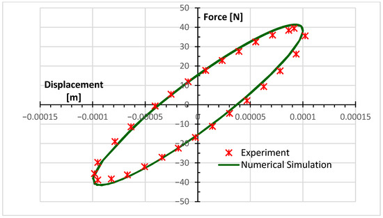
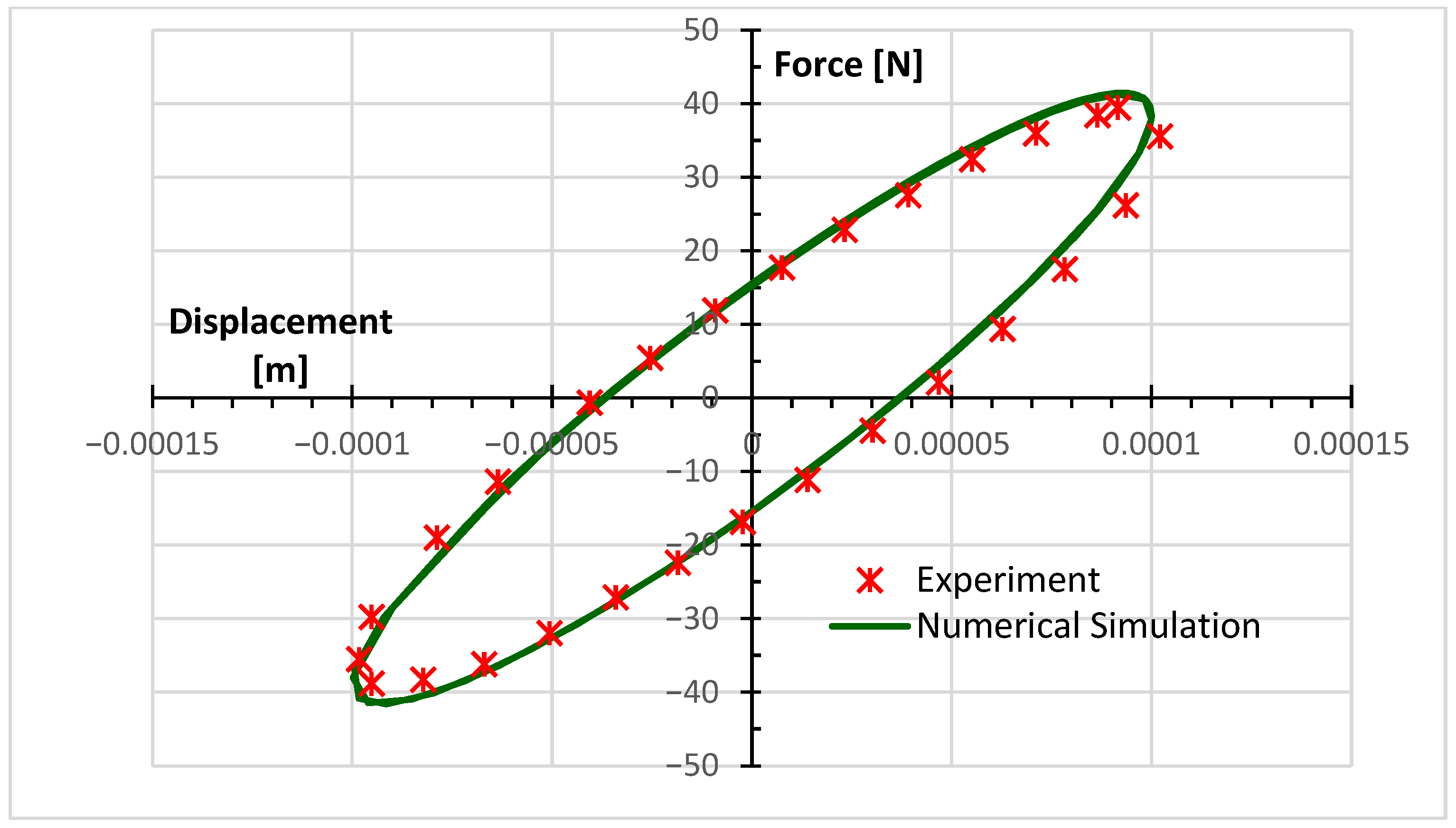
The comparison between the numerical and experimental curves, presented in Figure 7, shows very good agreement in terms of loop shape, stiffness, and energy dissipation. This confirms that the adopted number of Prony terms and the identified parameters provide a sufficiently accurate representation of the VE material for subsequent frame-level analyses.
Figure 7.
Force–displacement hysteresis comparison between DMA test and Abaqus simulation.
3.3.2. FEM Analysis in Abaqus Using Prony Series Representation
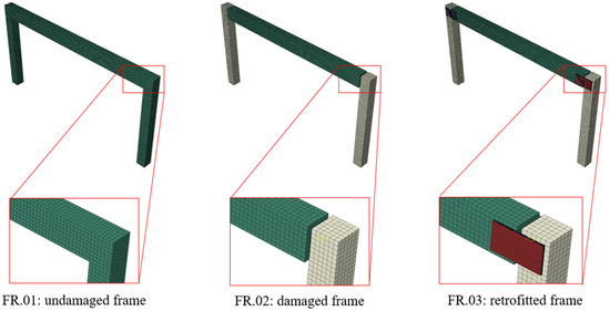
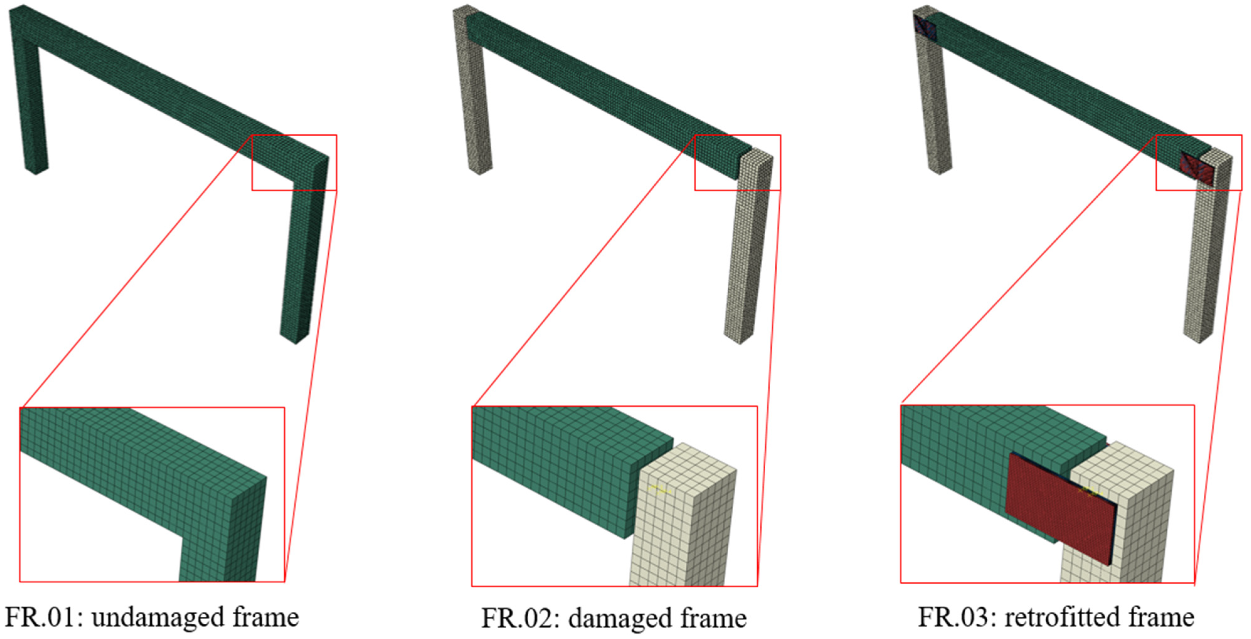
In this paper, the term frame refers to a single-storey, single-bay planar (portal) RC frame analysed in-plane; the FE discretisation is three-dimensional, using C3D8R (8-node linear brick, reduced integration) solid elements. To investigate the influence of damage and retrofitting on the dynamic performance of RC frames, a comparative numerical study was performed for three representative configurations: undamaged (FR.01), damaged (FR.02), and retrofitted (FR.03). This arrangement enables a systematic assessment of how the frame response evolves from an intact monolithic system to a damaged structure with degraded joints and finally to a retrofitted system with VE layers.
A three-dimensional FE model of a one-bay, one-storey RC frame was developed in Abaqus. Although the FE discretisation is three-dimensional, the excitation and evaluated response quantities are restricted to the plane of the frame (in-plane behaviour only). In all frames, concrete was assumed to behave as a linear elastic material. This research focused on the global dynamic response of the frame systems under relatively small deformation levels, where linear material behaviour provides an effective representation of structural stiffness. Accordingly, local nonlinear effects such as cracking, crack propagation, and concrete material nonlinearity were not explicitly modelled in Abaqus. The geometry of all three models was identical and consists of two RC columns and a connecting RC beam; only the joint behaviour at the beam–column interfaces was varied. In the undamaged configuration FR.01, the joints were modelled as fully rigid, representing an intact monolithic connection. In the damaged configuration FR.02, the joints were idealised as pinned connections to reflect the loss of stiffness caused by cracking and crushing of concrete in the joint region, with the remaining load transfer assumed to occur mainly through the reinforcement.
The retrofitted frame FR.03 was derived from the damaged configuration by inserting VE layers at the beam–column interfaces, thereby restoring continuity and introducing additional damping. The VE layers were assigned the same Prony series material model as calibrated from the DMA tests. Concrete was modelled as a homogeneous linear elastic material, as the intent of this initial analysis was to build a simple model in order to evaluate whether the proposed retrofitting technique can improve the overall structural response of the RC frame. The VE layers were bonded to the concrete surfaces using tie constraints, while rigid body constraints and reference points were used to apply boundary conditions and control the loading. The column bases were fully fixed.
To evaluate the dynamic behaviour, steady-state harmonic response analyses (frequency sweeps) were carried out to identify resonant response characteristics. In addition, time-history analyses with ground-motion records were performed to obtain displacement histories at selected nodes. This modelling strategy enables a direct comparison between FR.01, FR.02 and FR.03, and thus a quantitative assessment of the efficiency of the VE retrofitting scheme in restoring stiffness and enhancing the energy-dissipation capacity of the RC frame. The geometry of the analysed one-bay, one-storey RC frame and the locations of the VE layers in configuration FR.03 are shown in Figure 8.
Figure 8.
Numerical models of undamaged (FR.01), damaged (FR.02), and retrofitted (FR.03) frames.
The damaged reference frame FR.02 was intentionally modelled with hinge-like beam–column joints to represent a limit case of severe joint degradation. This modelling assumption corresponds to an extreme damage scenario in which the rotational stiffness of the connection is almost entirely lost by crushed concrete in the beam–column interface. As such, FR.02 does not aim to reproduce a typical damaged joint condition but rather provides a conservative lower-bound stiffness and load-carrying capacity of the frame. Any real damaged reinforced concrete joint is therefore expected to exhibit stiffness and performance equal to or higher than that of FR.02.
4. Results
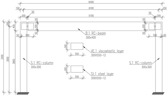
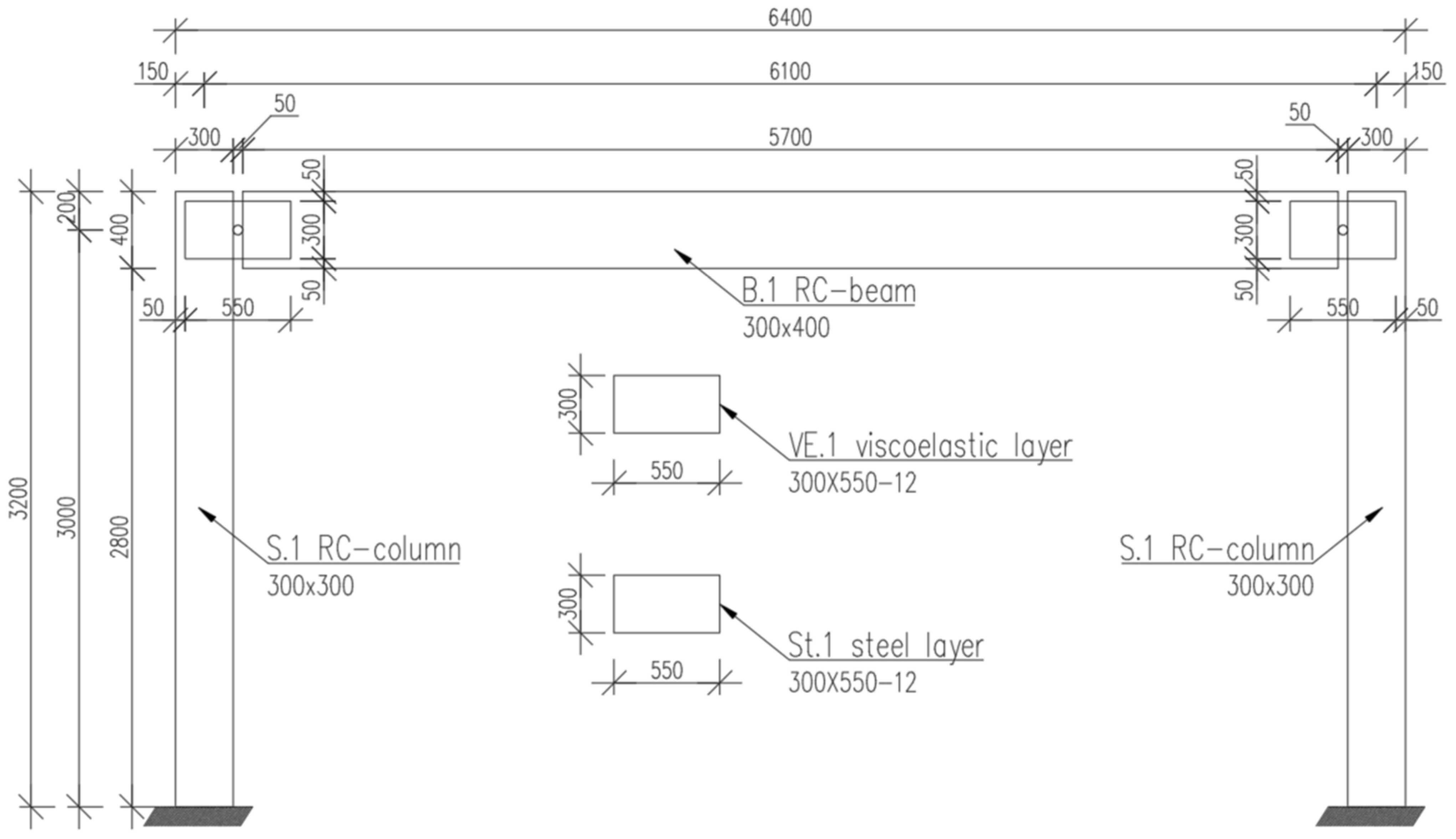
Numerical analyses were conducted in the frequency and time domains to evaluate the effectiveness of the proposed retrofitting technique. Three frame configurations were examined: the undamaged frame (FR.01), the damaged frame (FR.02), and the retrofitted frame (FR.03) by comparing their dynamic responses. The geometry of the retrofitted frame is illustrated in Figure 9, where a viscoelastic (VE) layer and a thin steel layer are introduced in combination at the beam–column joint region, representing the proposed retrofitting technique. In the damaged frame configuration, these additional layers were omitted to represent the loss of joint integrity, while the undamaged frame was modelled with fully intact joints.
Figure 9.
Geometric layout of the RC frame (units in mm).
In the frequency domain analysis, each frame was subjected to harmonic loading over a range of excitation frequencies to obtain their corresponding frequency response functions. This approach allowed the identification of dominant resonant frequencies and the evaluation of how retrofitting influenced the overall stiffness and damping of the structures.
In the time-domain analysis, the frames were subjected to base excitation in the form of ground acceleration derived from a recorded earthquake seismogram. The structural responses were assessed in terms of top-node displacements over the duration of the ground motion. By comparing these time histories among the three frame configurations, the effectiveness of viscoelastic retrofitting in reducing lateral displacements was quantitatively evaluated.
4.1. Frequency-Domain Analysis
To investigate the dynamic characteristics of the frames, a steady-state harmonic response analysis was performed in Abaqus. This procedure enables a direct evaluation of resonant displacement amplitudes over a prescribed frequency sweep while accounting for the energy-dissipative behaviour of the viscoelastic layers through the Prony series material definition.
For comparison, all three frame configurations, undamaged (FR.01), damaged (FR.02), and retrofitted (FR.03), were analysed under identical boundary and loading conditions. The frames were analysed under their self-weight; however, additional masses were taken into account to represent the slab resting on the RC frame. A concentrated (lumped) mass of 1000 kg was assigned at each beam-end top node to represent the tributary floor mass and associated non-structural masses.
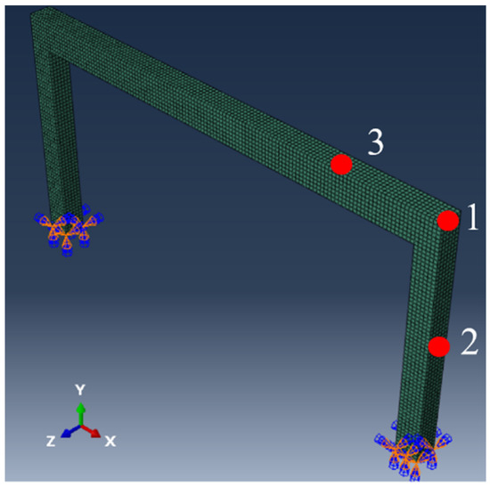
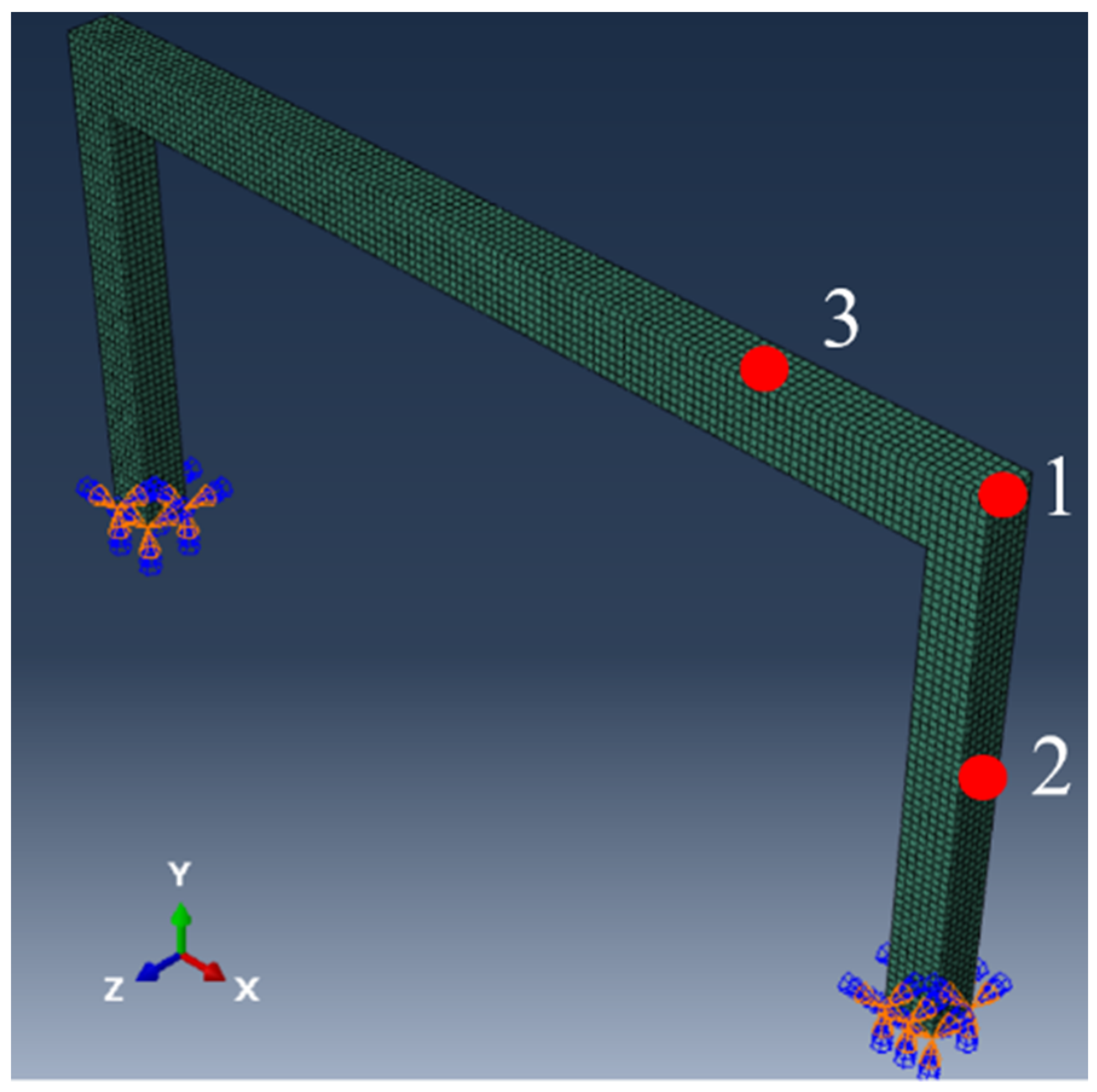
From each frame, three representative nodes were selected for detailed examination of their resonant frequency response characteristics. Node 1 is located at the outer corner of the beam–column joint. Node 2 is situated on the outer face of the column at mid-level along its clear height. Node 3 is positioned on the top surface of the beam, at a distance equal to one-quarter of the beam’s clear span from the column faces. All these nodes are positioned in the mid-plane between the front and back faces of the frame. These nodes were strategically chosen to detect the global and local vibration responses of the structure, particularly around the beam–column joint region. The locations of the analysed nodes are illustrated in Figure 10.
Figure 10.
Nodes examined in the frequency domain analysis.
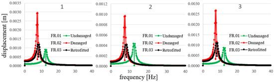
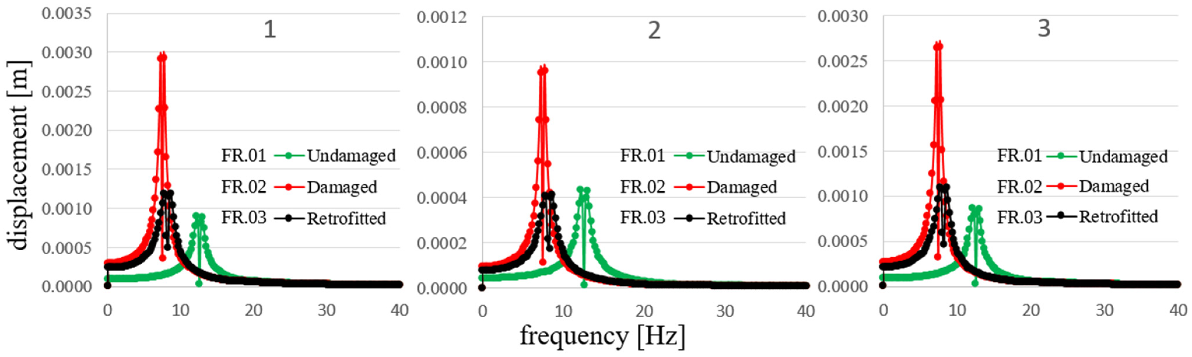
In the frequency-domain analysis, a uniform harmonic pressure load of 1.0 kPa was applied at the top corner of the frames to simulate the effect of in-plane horizontal excitation. The excitation frequency varied from 0 Hz to 40 Hz in steps of 0.02 Hz to capture the wide response spectrum of each frame configuration. As a result, the resonant frequencies of the selected nodes were analysed by identifying the peak displacement amplitudes, which served as indicators of the frames’ dynamic characteristics. The comparison among the three configurations allowed the assessment of whether the retrofitted frame contributed to the reduction in displacement amplitudes at resonance. In this way, the effectiveness of the viscoelastic retrofitting in improving the dynamic performance of the RC frame was quantitatively evaluated. Figure 11 shows the resonant frequency response of each frame for the nodes presented in Figure 10.
Figure 11.
The resonant frequency response of each frame for the three examined nodes 1 2 3.
The peak displacement amplitudes reported in Table 2 correspond to the maximum values obtained from the discrete frequency sweep (step 0.02 Hz) in the vicinity of the first resonance. Therefore, the reported peaks represent the maximum among sampled frequency points near the resonance. All displacements listed in Table 2 are in-plane displacement amplitudes at the respective nodes under harmonic excitation.
Table 2.
Comparison of first resonant frequencies and corresponding maximum in-plane displacement amplitudes of the analysed frames at selected nodes.
Table 2 above highlights the first resonant frequencies and the trends in the maximum in-plane displacement amplitudes at the first resonant frequency across the frames for each selected node. The first resonant frequency is 12.54 Hz in FR.01, decreases to 7.45 Hz in FR.02, then rises to 8.23 Hz in FR.03. For Node 1, the displacement amplitude increases by 228.91% from FR.01 to FR.02, followed by a further 33.68% increase relative to FR.01 in FR.03 (equivalent to a 59.36% decrease relative to FR.02). For Node 2, the amplitude rises by 122.38% from FR.01 to FR.02, then decreases by 4.56% relative to FR.01 in FR.03 (or by 57.02% relative to FR.02). For Node 3, it increases by 207.03% from FR.01 to FR.02, and by 25.68% relative to FR.01 in FR.03 (corresponding to a 58.87% decrease relative to FR.02). Overall, FR.02 produces the greatest amplifications at all nodes compared to the reference FR.01, while FR.03 displays changes that are generally improved relative to FR.02.
Based on the observations made for mode shapes, for the single-bay, single-storey frame considered in this study, the addition of VE layers did not alter the in-plane mode shapes in a way that produces undesirable dynamic or torsional effects.
The results of frequency domain analysis demonstrated that the retrofitted frame (FR.03) exhibited a reduction in the amplitude of resonant vibrations at all three analysed nodes compared to the damaged (FR.02) configuration. This attenuation in displacement amplitude indicates the potential of viscoelastic layers in dissipating energy and enhancing the overall damping capacity of the RC frame structure.
4.2. Time-Domain Analysis
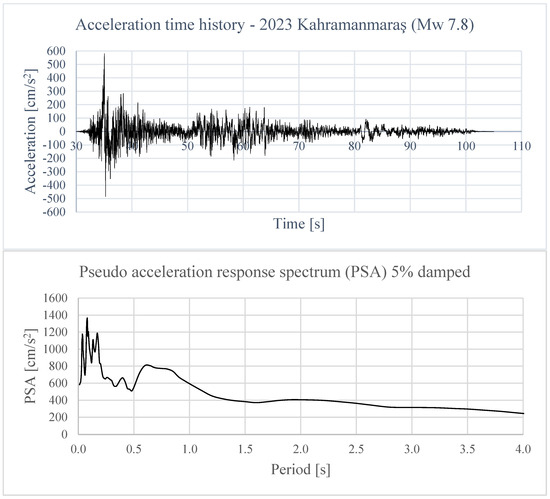
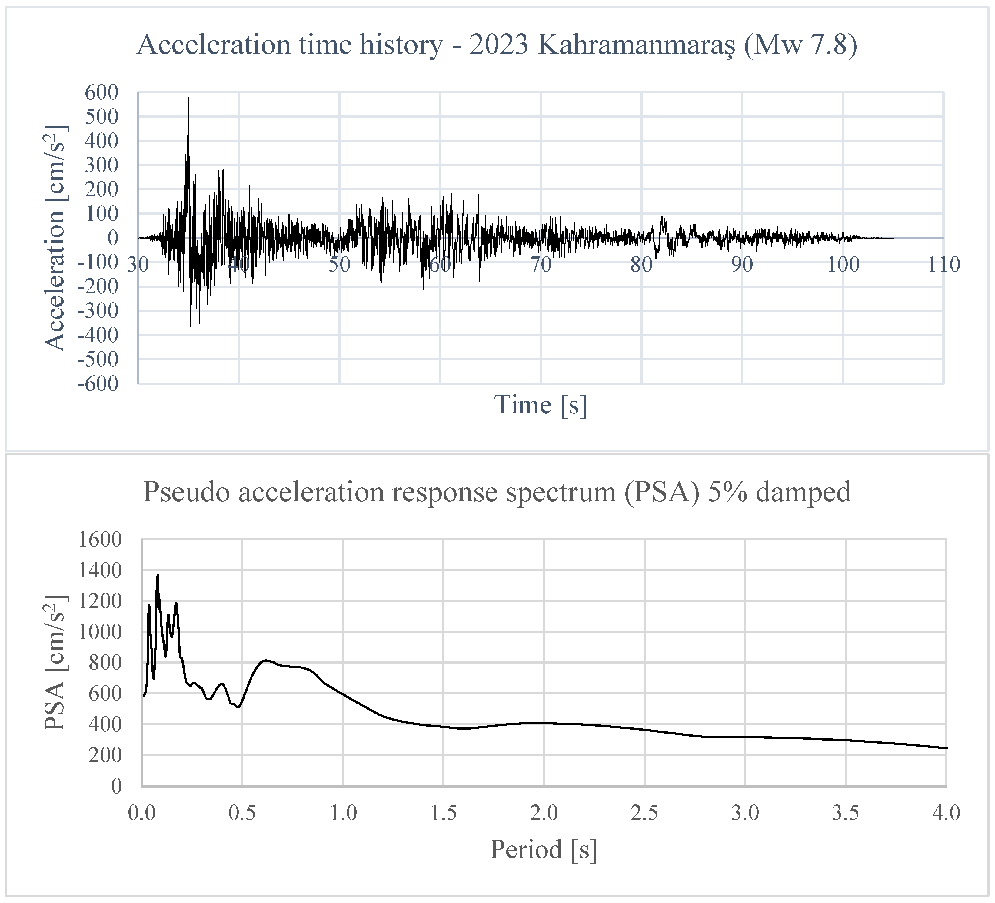
To assess the seismic performance of the RC frames, dynamic analyses were performed in Abaqus in the time domain. The procedure involved direct evaluation of the structural response of the frames under real earthquake loading. The three frame configurations—undamaged (FR.01), damaged (FR.02), and retrofitted (FR.03)—were subjected to one-directional base excitation defined by a recorded earthquake ground acceleration [49]. The selected ground motion, the 2023 Kahramanmaras earthquake with moment magnitude (Mw) 7.8, was applied at the ground level to reproduce conditions of seismic excitation in the plane of the RC frame. The ground motion record was obtained from the Engineering Strong Motion (ESM) database [49] and used in the numerical analyses in its processed form as provided by the database. The accelerogram is instrument-corrected and baseline-adjusted according to the ESM processing protocol; therefore, no additional baseline correction was applied. No further high-pass or low-pass filtering was introduced in order to preserve the original frequency content of the record. The ground motion was applied without amplitude scaling, using its original peak ground acceleration of PGA = 578.14 cm/s2. The seismogram record of the applied earthquake and its pseudo acceleration response spectrum for 5% damping can be seen in Figure 12.
Figure 12.
Acceleration time history of the 2023 Kahramanmaraş (Mw 7.8) earthquake and its Pseudo acceleration response spectra (Network: TK, Station code: NAR) [49].
The record selection and the use of an unscaled accelerogram are intended for a comparative case study assessment of the three frame configurations. The frames were subjected to the ground motion over the selected time interval between 30 s and 50 s, which contains the largest-amplitude segment of the record used in this study. The adoption of a shortened time window can be justified by the short and relatively stiff nature of the analysed frames, which develop their dominant dynamic response over a short period compared to more flexible, slender structures. As the study focuses on a parametric comparison of frame configurations, the time interval with the highest energy input was selected to maximise excitation demand and comparability across cases. Although this window captures the largest-amplitude segment of the accelerogram and activates the governing response mechanisms, it may not represent the worst-case scenario; full record and/or multiple ground motion analyses are left for future work. It should also be noted that, as only a single unscaled ground motion (Kahramanmaraş 2023) was used, the present results are limited to this case study scenario; extending the analysis to additional ground motions would further strengthen and validate the proposed solution.
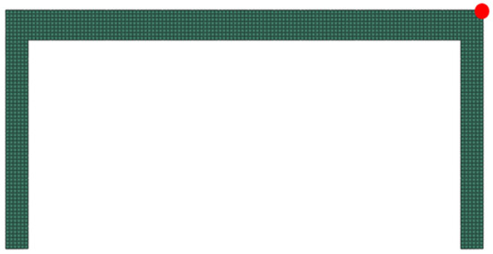
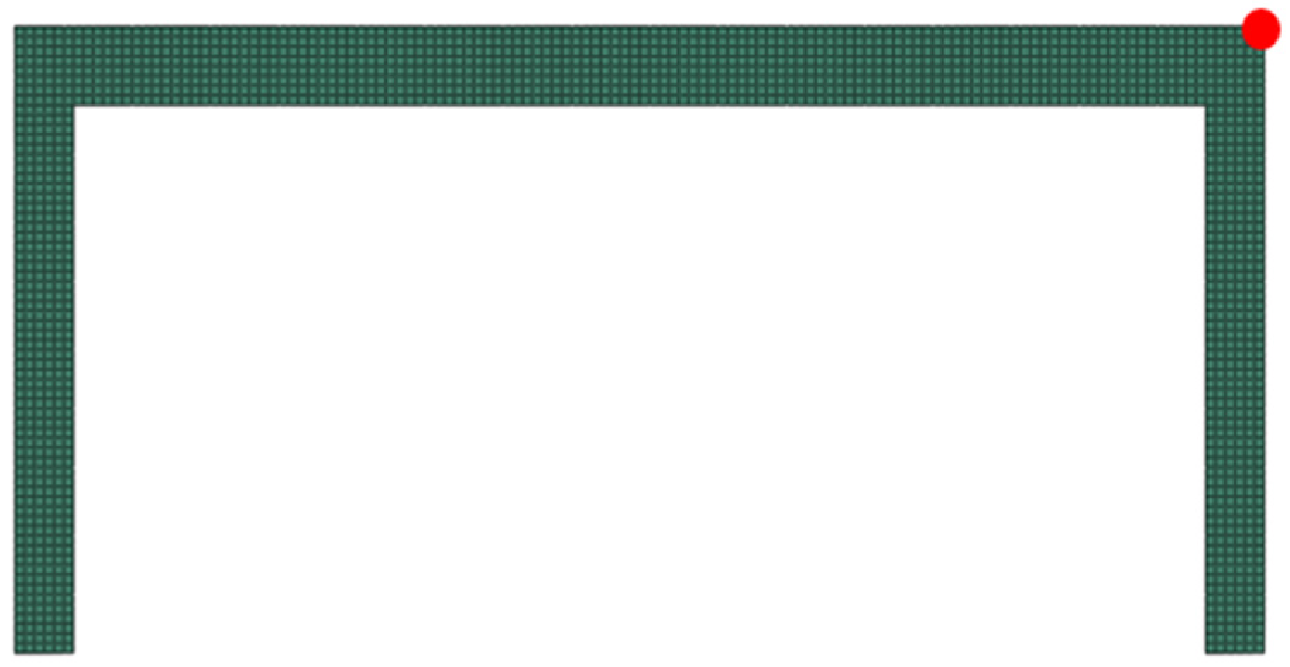
The viscoelastic properties of the retrofitted frame were modelled using a time-dependent Prony series formulation to account for energy dissipation during ground motion. The dynamic responses of all frames were evaluated in terms of the horizontal displacement histories of the top node. This comparison enabled the assessment of how viscoelastic retrofitting influences the overall in-plane displacement of the frame under earthquake excitation. The selected monitoring point (top corner node) used for tracking the dynamic response is highlighted in Figure 13.
Figure 13.
Location of the monitored top node in the 1-bay, 1-storey RC frame.
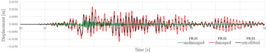
The horizontal displacement responses of the top node for the three frame configurations are presented in Figure 14.
Figure 14.
Horizontal displacement time histories of the top node for the undamaged (FR.01), damaged (FR.02), and retrofitted (FR.03) frames.
In Table 3, the analysis of the peak horizontal displacement of the top node within the 30 s–50 s time window shows important variations across the three frame configurations. Relative to the reference frame FR.01, the FR.02 configuration exhibited a substantial increase of 295.55% in peak displacement. In contrast, the FR.03 configuration achieved a significant mitigation of this increased response. While FR.03’s displacement remains 172.72% higher than the undamaged FR.01 baseline frame, it represents a significant 31.05% reduction when compared directly to the excessive peak movement observed in FR.02.
Table 3.
Peak horizontal displacements of the top node and relative changes across frames (time window: 30 s–50 s).
As seen in Table 3, the retrofitted frame (FR.03) exhibited a clear reduction in displacement amplitude throughout the duration of the applied ground acceleration when compared to the damaged (FR.02) frame. The damaged frame showed the largest response amplitudes due to the lack of joint stiffness and energy dissipation. This reduction in displacement highlights the capability of the proposed retrofitting technique in controlling vibration amplitude and enhancing the damping behaviour of the RC frame under seismic excitation.
Overall, both frequency- and time-domain analyses indicated that the damaged frame (FR.02) exhibited reduced stiffness and increased displacement responses compared to the undamaged frame (FR.01). The retrofitted frame (FR.03) consistently demonstrated improved dynamic performance, with higher modal frequencies, lower displacement amplitudes, and enhanced energy dissipation. These results confirmed the effectiveness of the proposed viscoelastic steel retrofitting technique in controlling seismic responses of the RC frame.
5. Conclusions
The findings of the present study directly address concerns raised in previous research regarding conventional stiffness- and strength-based retrofitting strategies. As highlighted by Zhao et al. [28] and Tahamouli-Roudsari et al. [29], while such conventional interventions can effectively enhance lateral resistance, they may also lead to increased acceleration demands, unfavourable force redistribution, and a reduction in global ductility, potentially transferring additional stresses to existing structural components and accelerating damage under seismic loading. In contrast, the retrofitting approach investigated in this study focuses on enhancing the ductility and energy dissipation capacity of the RC frame through the incorporation of viscoelastic layers at beam–column joints, rather than significantly increasing structural stiffness or strength. This strategy allows the structure to respond in a manner more consistent with its original seismic design philosophy, limiting force amplification and reducing the risk of interaction effects.
Dynamic Mechanical Analysis (DMA) tests were conducted to develop an effective viscoelastic (VE) material model for numerical simulations in Abaqus. The experimentally obtained curves were approximated in MATLAB and implemented in terms of a Prony series representation to define the VE material behaviour in the finite element software Abaqus. The obtained material model was verified through the simulation of the experimental DMA test in an identical finite element model simulation. The integration of DMA data, curve fitting, and Prony series implementation establishes a systematic and advanced methodology for viscoelastic material characterisation, enabling rapid optimisation of different geometrical and/or material configurations during the initial stages of research. Once the effective material model had been verified and established for the considered VE material, an RC frame in three states—undamaged, damaged, and retrofitted—was subjected to both frequency-domain and time-domain analyses. Comparative analyses of these three models were performed to evaluate the effectiveness of the retrofitting technique using VE layers backed by steel plates.
The use of the Prony series to define viscoelastic materials in finite element software such as Abaqus provides a powerful approach to significantly reduce computational cost while maintaining high accuracy of the results for the analysed one-bay, one-storey frame and the considered VE material. The complex behaviour of viscoelastic materials can be effectively modelled using the Maxwell model by increasing the number of Maxwell terms; however, special attention must be paid during curve fitting, as an excessive number of terms may lead to overfitting and deviations from the actual material behaviour. We therefore recommend adopting an iterative approach, gradually increasing the number of Maxwell terms. Moreover, the methodology applied in this study, comparing experimental DMA tests with numerical DMA simulations via the Prony series definition obtained through curve fitting, represents a simple yet robust procedure for tuning the material behaviour. One key advantage of using DMA-derived Prony series is the efficiency: it allows rapid characterisation of viscoelastic properties compared with conventional stress relaxation or other time-dependent experiments, which can take hours or even days depending on the material and test protocol.
At this stage, the contribution of viscoelastic layers to the global dynamic behaviour of RC frames has been investigated for the proposed retrofitting technique. The results demonstrated that, under the examined loading conditions and modelling assumptions, VE layers applied at beam–column joints can effectively damp vibrations and reduce in-plane horizontal displacements of the one-bay, one-storey RC frame considered in this study.
6. Limitations of the Current Study and Future Work
While the present investigation focuses on global dynamic behaviour under linear elastic assumptions, it may be regarded as a benchmark case study aimed at understanding the direct application of viscoelastic layers and their influence on the overall dynamic response of RC frames. Building upon these findings, future work is planned to extend the proposed retrofitting technique to nonlinear concrete models incorporating progressive damage development in beam–column joint regions. This progressive modelling strategy will be investigated through both advanced numerical simulations and laboratory experiments. While laboratory testing may initially rely on idealised damage states, numerical models will be developed to explicitly simulate damage evolution under dynamic loading. Such an approach will allow systematic assessment of the effectiveness of the proposed retrofitting method across intermediate joint stiffness levels and varying damage states, thus providing a more realistic evaluation of its applicability to existing RC structures.
The one-bay, one-storey frame analysed in this research represents a typical frame segment extracted from a multi-storey RC building and should therefore be viewed as an analysis of a representative sub-assembly. Accordingly, the findings should be interpreted in light of certain limitations, including a single frame geometry, one viscoelastic material configuration, and a single ground motion record. A comprehensive building-scale assessment, accounting for multi-storey effects, infill walls, and interaction or coupling phenomena, constitutes an important direction for future research. Further studies could explore a wider variety of viscoelastic materials, temperature effects, different joint configurations, and multiple seismic scenarios to better understand the broader applicability and robustness of the proposed retrofitting technique.
Author Contributions
Conceptualization, Z.M.P.; Methodology, C.Y. and Z.M.P.; Software, C.Y.; Validation, C.Y. and Z.M.P.; Formal analysis, C.Y. and Z.M.P.; Investigation, C.Y. and Z.M.P.; Resources, C.Y. and Z.M.P.; Data curation, C.Y.; Writing—original draft, C.Y.; Writing—review & editing, C.Y. and Z.M.P.; Visualization, C.Y.; Supervision, Z.M.P.; Project administration, Z.M.P.; Funding acquisition, C.Y. and Z.M.P. All authors have read and agreed to the published version of the manuscript.
Funding
This research was funded by the Poznan University of Technology, Grant No. 0411/SBAD/0012.
Institutional Review Board Statement
Not applicable.
Informed Consent Statement
Not applicable.
Data Availability Statement
The original contributions presented in the study are included in the article, further inquiries can be directed to the corresponding author.
Conflicts of Interest
The authors declare no conflict of interest.
Abbreviations
| VE | Viscoelastic |
| RC | Reinforced concrete |
| DMA | Dynamic mechanical analysis |
| RMSE | Root mean square error |
| FE | Finite element |
| FR | Frame |
| ESM | Engineering strong motion |
| PGA | Peak ground acceleration |
References
- Schwarz, J.; Abrahamczyk, L.; Leipold, M.; Wenk, T. Vulnerability assessment and damage description for R.C. frame structures following the EMS-98 principles. Bull. Earthq. Eng. 2015, 13, 1141–1159. [Google Scholar] [CrossRef] [Scilit]
- Idow Mohamed, H.; Ostovar Ravari, S.; Resatoglu, R. Structural And Cost Analysis Of Reinforced Concrete And Steel Framed Structures: A Comparative Study In Lefkoşa, North Cyprus. In Proceedings of the International Conference of Contemporary Affairs in Architecture and Urbanism-ICCAUA, Istanbul, Turkey, 14–15 June 2023; Volume 6, pp. 1179–1192. [Google Scholar] [CrossRef] [Scilit]
- Wang, Z.X.; Fan, H.T.; Zhao, H.J. Analysis of the Seismic Performance of RC Frame Structures with Different Types of Bracings. In Applied Mechanics and Materials; Trans Tech Publications, Ltd.: Bäch, Switzerland, 2012; Volume 166–169, pp. 2209–2215. [Google Scholar] [CrossRef] [Scilit]
- Kim, S.; Moon, T.; Kim, S.J. Effect of Uncertainties in Material and Structural Detailing on the Seismic Vulnerability of RC Frames Considering Construction Quality Defects. Appl. Sci. 2020, 10, 8832. [Google Scholar] [CrossRef] [Scilit]
- Truong, G.T.; Kim, J.; Choi, K. Seismic performance of reinforced concrete columns retrofitted by various methods. Eng. Struct. 2017, 134, 217–235. [Google Scholar] [CrossRef] [Scilit]
- Ates, S.; Kahya, V.; Yurdakul, M.; Adanur, S. Damages on reinforced concrete buildings due to consecutive earthquakes in Van. Soil Dyn. Earthq. Eng. 2013, 53, 109–118. [Google Scholar] [CrossRef] [Scilit]
- Valente, M. Seismic Upgrading Strategies for Non-Ductile Plan-Wise Irregular R/C Structures. Procedia Eng. 2013, 54, 539–553. [Google Scholar] [CrossRef] [Scilit]
- Kabashi, N.; Muhaxheri, M.; Krasniqi, E.; Murati, Y.; Latifi, F. Advancements in Fiber-Reinforced Polymer (FRP) Retrofitting Techniques for Seismic Resilience of Reinforced Concrete Structures. Buildings 2025, 15, 587. [Google Scholar] [CrossRef] [Scilit]
- Sousa, I.; Peres, R.; Couto, R.; Bento, R.; Castro, J.M. Numerical Modelling and Damage Assessment Criteria for FRP-Retrofitted RC Columns. Buildings 2025, 15, 188. [Google Scholar] [CrossRef] [Scilit]
- Sabbahfar, P.; Melo, J.; Costa, A.; Varum, H.; Rodrigues, H. Cyclic Behavior of Seismically Non-Conforming Interior Reinforced Concrete Beam–Column Joints. Buildings 2025, 15, 202. [Google Scholar] [CrossRef] [Scilit]
- Hadjadj, A.; Ouazir, A.; Ouazir, M.; Djeffal, H. Nonlinear Analysis of Hybrid GFRP-Steel Reinforced Beam-Column Joints Under Cyclic and Axial Loading. Buildings 2025, 16, 72. [Google Scholar] [CrossRef] [Scilit]
- Thermou, G.E.; Elnashai, A.S. Seismic retrofit schemes for RC structures and local-global consequences. Prog. Struct. Eng. Mater. 2005, 8, 1–15. [Google Scholar] [CrossRef] [Scilit]
- Parvin, A.; Altay, S.; Yalcin, C.; Kaya, O. CFRP Rehabilitation of Concrete Frame Joints with Inadequate Shear and Anchorage Details. J. Compos. Constr. 2009, 14, 72–82. [Google Scholar] [CrossRef] [Scilit]
- Del Vecchio, C.; Di Ludovico, M.; Balsamo, A.; Prota, A.; Manfredi, G.; Dolce, M. Experimental Investigation of Exterior RC Beam-Column Joints Retrofitted with FRP Systems. J. Compos. Constr. 2014, 18, 04014002. [Google Scholar] [CrossRef] [Scilit]
- Lu, Z.-D.; Liu, C.-Q.; Zhang, K.-C.; Wang, H.-J. Experimental study on the seismic performance of enveloped steel strengthened RC frame joint. J. Sichuan Univ. 2010, 42, 56–62. [Google Scholar]
- Akguzel, U.; Pampanin, S. Effects of variation of axial load and bidirectional loading on seismic performance of GFRP retrofitted reinforced concrete exterior Beam-Column joints. J. Compos. Constr. 2010, 14, 94–104. [Google Scholar] [CrossRef] [Scilit]
- Torabi, A.; Maheri, M.R. Seismic repair and retrofit of RC Beam–Column joints using stiffened steel plates. Iran. J. Sci. Technol. Trans. Civ. Eng. 2016, 41, 13–26. [Google Scholar] [CrossRef] [Scilit]
- Pimanmas, A.; Chaimahawan, P. Shear strength of beam–column joint with enlarged joint area. Eng. Struct. 2010, 32, 2529–2545. [Google Scholar] [CrossRef] [Scilit]
- Biddah, A.; Ghobarah, A.; Aziz, T.S. Upgrading of Nonductile Reinforced Concrete Frame Connections. J. Struct. Eng. 1997, 123, 1001–1010. [Google Scholar] [CrossRef] [Scilit]
- Chen, Z.-M.; Li, A. Experimental study on beam-column connections strengthened with high-strength steel wire mesh and polymer mortar. Jianzhu Jiegou Xuebao 2006, 27, 10–15. [Google Scholar]
- Ahmed, H.A.; Tanoli, W.A. Seismic Retrofitting of RC Buildings Using a Performance-Based Approach for Risk Resilience and Vulnerability Assessment. Buildings 2025, 15, 1333. [Google Scholar] [CrossRef] [Scilit]
- Valente, M. Seismic Protection of R/C Structures by a New Dissipative Bracing System. Procedia Eng. 2013, 54, 785–794. [Google Scholar] [CrossRef] [Scilit]
- Tena-Colunga, A.; Hernández-Ramírez, H.; Godínez-Domínguez, E.A. Review of retrofit and strengthening strategies used in buildings in Mexico city after strong earthquakes. In Proceedings of the 9th International Conference on Computational Methods in Structural Dynamics and Earthquake Engineering 2023, Athens, Greece, 12–14 June 2023; pp. 316–391. [Google Scholar] [CrossRef] [Scilit]
- Ezoddin, A.; Kheyroddin, A.; Gholhaki, M. Experimental and numerical investigation on the seismic retrofit of RC frames with linked column frame systems. J. Build. Eng. 2021, 44, 102956. [Google Scholar] [CrossRef] [Scilit]
- Li, S.; Jiang, H.; He, L. Study of a new type of replaceable coupling beam in reinforced concrete shear wall structures. Struct. Des. Tall Spec. Build. 2019, 28, e1620. [Google Scholar] [CrossRef] [Scilit]
- Saravanan, M.; Goswami, R.; Palani, G.S. Replaceable Fuses in Earthquake Resistant Steel Structures: A Review. Int. J. Steel Struct. 2018, 18, 868–879. [Google Scholar] [CrossRef] [Scilit]
- Ullah, R.; Vafaei, M.; Alih, S.C.; Waheed, A. A replaceable sandwiched metallic fuse damper for seismic protection of braced frames. Eng. Struct. 2023, 298, 117072. [Google Scholar] [CrossRef] [Scilit]
- Zhao, J.; Qiu, H.; Sun, J.; Jiang, H. Seismic performance evaluation of different strategies for retrofitting RC frame buildings. Structures 2021, 34, 2355–2366. [Google Scholar] [CrossRef] [Scilit]
- Tahamouli-Roudsari, M.; Entezari, A.; Hadidi, M.; Gandomian, O. Experimental assessment of retrofitted RC frames with different steel braces. Structures 2017, 11, 206–217. [Google Scholar] [CrossRef] [Scilit]
- Shu, Z.; You, R.; Xie, Y. Viscoelastic dampers for vibration control of building structures: A state-of-art review. J. Earthq. Eng. 2024, 28, 3558–3585. [Google Scholar] [CrossRef] [Scilit]
- Samali, B.; Kwok, K.C.S. Use of viscoelastic dampers in reducing wind- and earthquake-induced motion of building structures. Eng. Struct. 1995, 17, 639–654. [Google Scholar] [CrossRef] [Scilit]
- Zhang, H.; Li, A.; Su, Y.; Xu, G.; Sha, B. Viscoelastic dampers for civil engineering structures: A systematic review of constructions, materials, and applications. J. Build. Eng. 2024, 96, 110597. [Google Scholar] [CrossRef] [Scilit]
- Kim, J.; Ryu, J.; Chung, L. Seismic performance of structures connected by viscoelastic dampers. Eng. Struct. 2006, 28, 183–195. [Google Scholar] [CrossRef] [Scilit]
- Tani, T.; Yoshitomi, S.; Tsuji, M.; Takewaki, I. High-performance control of wind-induced vibration of high-rise building via innovative high-hardness rubber damper. Struct. Des. Tall Spec. Build. 2009, 18, 705–728. [Google Scholar] [CrossRef] [Scilit]
- Sato, D.; Osabel, D.M.; Kasai, K. Evaluation method for practical application of viscoelastic damper using equivalent sinusoidal waveforms of long-duration random excitations in along- and across-wind directions. Eng. Struct. 2022, 254, 113735. [Google Scholar] [CrossRef] [Scilit]
- Huang, X.; Xu, Z.; Xiao, H. Experimental study on seismic behavior of damaged Beam-Column joints retrofitted by viscoelastic Steel-Enveloped elements. Buildings 2023, 13, 702. [Google Scholar] [CrossRef] [Scilit]
- Karim, K.; Chen, G. Surface damping effect of anchored constrained viscoelastic layers on the flexural response of simply supported structures. Mech. Syst. Signal Process. 2011, 27, 419–432. [Google Scholar] [CrossRef] [Scilit]
- Torvik, P.A.; Bagley, R.L. On the appearance of the fractional derivative in the behavior of real materials. J. Appl. Mech. 1984, 51, 294–298. [Google Scholar] [CrossRef] [Scilit]
- Mainardi, F. Fractional Calculus and Waves in Linear Viscoelasticity: An Introduction to Mathematical Models; Imperial College Press: London, UK, 2010. [Google Scholar] [CrossRef]
- Podlubny, I. Fractional Differential Equations; Academic Press: Cambridge, MA, USA, 1999. [Google Scholar]
- Lewandowski, R.; Litewka, P.; Łasecka-Plura, M.; Pawlak, Z.M. Dynamics of structures, frames, and plates with viscoelastic dampers or layers: A literature review. Buildings 2023, 13, 2223. [Google Scholar] [CrossRef] [Scilit]
- Bonfanti, A.; Kaplan, J.L.; Charras, G.; Kabla, A. Fractional viscoelastic models for power-law materials. Soft Matter 2020, 16, 6002–6020. [Google Scholar] [CrossRef] [Scilit] [PubMed]
- Xu, Y.; He, Q.; Guo, Y.-Q.; Huang, X.-H.; Dong, Y.-R.; Hu, Z.-W.; Kim, J. Experimental and theoretical investigation of viscoelastic damper by applying fractional derivative method and internal variable theory. Buildings 2023, 13, 239. [Google Scholar] [CrossRef] [Scilit]
- Li, Q.-Q.; Xu, Z.-D.; Dong, Y.-R.; He, Z.-H.; Zhu, C.; Lu, Y. Effects of mechanical nonlinearity of viscoelastic dampers on the seismic performance of viscoelastically damped structures. Soil Dyn. Earthq. Eng. 2021, 150, 106936. [Google Scholar] [CrossRef] [Scilit]
- Pawlak, Z.M.; Denisiewicz, A. Identification of the fractional Zener model parameters for a viscoelastic material over a wide range of frequencies and temperatures. Materials 2021, 14, 7024. [Google Scholar] [CrossRef] [Scilit]
- Ghobadi, E.; Shutov, A.; Steeb, H. Parameter identification and validation of shape-memory polymers within the framework of finite strain viscoelasticity. Materials 2021, 14, 2049. [Google Scholar] [CrossRef] [Scilit] [PubMed]
- Chen, H.; Trivedi, A.; Siviour, C. Application of linear viscoelastic continuum damage theory to the low and high strain rate response of thermoplastic polyurethane. Exp. Mech. 2020, 60, 925–936. [Google Scholar] [CrossRef] [Scilit]
- Chen, H. Thermomechanical Behaviours of Unfilled/Filled Thermoplastic Polyurethane. Doctoral Dissertation, University of Oxford, Oxford, UK, 2021. [Google Scholar]
- Luzi, L.; Lanzano, G.; Felicetta, C.; D’Amico, M.C.; Russo, E.; Sgobba, S.; Pacor, F.; ORFEUS Working Group 5. Engineering Strong Motion Database (ESM), Version 2.0; Istituto Nazionale di Geofisica e Vulcanologia (INGV): Rome, Italy, 2020. [CrossRef]


Disclaimer/Publisher’s Note: The statements, opinions and data contained in all publications are solely those of the individual author(s) and contributor(s) and not of MDPI and/or the editor(s). MDPI and/or the editor(s) disclaim responsibility for any injury to people or property resulting from any ideas, methods, instructions or products referred to in the content. |
© 2026 by the authors. Licensee MDPI, Basel, Switzerland. This article is an open access article distributed under the terms and conditions of the Creative Commons Attribution (CC BY) license.