


Abstract
Industrial Internet of Things (IIoT) networks, Microsoft Azure Internet of Things (IoT) Hub, and device twins (DvT) are increasingly recognized as core enablers of adaptive, data-driven manufacturing. This paper proposes a hierarchical IIoT framework that integrates industrial IoT networking, DvT for asset-level virtualisation, system-level digital twins (DT) for cell orchestration, and cloud-native services to support the digital transformation of brownfield, programmable logic controller (PLC)-centric modular automation (MA) environments. Traditional PLC/supervisory control and data acquisition (SCADA) paradigms struggle to meet interoperability, observability, and adaptability requirements at scale, motivating architectures in which DvT and IoT Hub underpin real-time orchestration, virtualisation, and predictive-maintenance workflows. Building on and extending a previously introduced conceptual model, the present work instantiates a multilayered, end-to-end design that combines a federated Message Queuing Telemetry Transport (MQTT) mesh on the on-premises side, a ZigBee-based backup mesh, and a secure bridge to Azure IoT Hub, together with a systematic DvT modelling and orchestration strategy. The methodology is supported by a structured analysis of relevant IIoT and DvT design choices and by a concrete implementation in a nine-cell MA laboratory featuring a robotic arm predictive-maintenance scenario. The resulting framework sustains closed-loop monitoring, anomaly detection, and control under realistic workloads, while providing explicit envelopes for telemetry volume, buffering depth, and latency budgets in edge-cloud integration. Overall, the proposed architecture offers a transferable blueprint for evolving PLC-centric automation toward more adaptive, secure, and scalable IIoT systems and establishes a foundation for future extensions toward full DvT ecosystems, tighter artificial intelligence/machine learning (AI/ML) integration, and fifth/sixth generation (5G/6G) and time-sensitive networking (TSN) support in industrial networks.
1. Introduction
The rapid advancement of manufacturing technologies, propelled by the paradigm of Industry 4.0, is fundamentally transforming the landscape of industrial automation. Traditional control architectures, predominantly based on discrete Programmable Logic Controllers (PLCs) and Supervisory Control and Data Acquisition (SCADA) systems, are undergoing a paradigm shift. Although PLC/SCADA hardware continues to play an important role in industrial automation, conventional isolated and hierarchical architectures are gradually giving way to more interoperable, adaptive, and intelligent frameworks suited for modern smart factories [1,2,3]. These systemic limitations underscore the imperative for a transition toward network-centric automation frameworks, in which the deployment of robust, modular, and hierarchical network architectures becomes a cornerstone for enabling scalable, integrated, and future-oriented industrial systems.
In this context, networking emerges as the backbone of digital transformation. It interconnects heterogeneous cyber-physical assets and supports advanced technologies such as device twins (DvT) and cloud-based orchestration, which rely on continuous, reliable data flows across field, edge, and cloud layers. By creating digital counterparts of physical assets, DvT enables real-time monitoring, predictive analytics, and edge-cloud synchronization, while cloud platforms such as Azure Internet of Things (IoT) Hub provide a secure and scalable communication fabric for managing large fleets of industrial devices and their virtual representations at scale. Nevertheless, many industrial deployments continue to engineer network, device modelling, and predictive analytics as loosely coupled layers connected through ad-hoc gateways, leading to fragile behaviour, duplicated modelling effort, and limited observability in brownfield PLC-centric environments. There remains a clear need for end-to-end architectures that jointly address resilient connectivity, scalable twin-centric orchestration, and concrete predictive maintenance workflows under realistic operational constraints.
This study addresses this need by building on and significantly extending the comprehensive conceptual model introduced in previous works by the authors [4,5], which seamlessly integrates four core advanced technologies: Industrial Internet of Things (IIoT) networking, digital-twin (DT) virtualisation, cloud-based orchestration, and predictive maintenance driven by artificial intelligence/machine learning (AI/ML). Here, this conceptual blueprint is instantiated as a hierarchical, network-centric IIoT framework centred on device virtualisation and centralised orchestration, implemented through a multi-layered architecture that represents a key contribution of this work. To overcome the scalability bottlenecks of traditional vertical segmentation, such as rigid topologies, protocol silos, and restricted cross-layer data flow, the proposed framework combines a federated Message Queuing Telemetry Transport (MQTT)-based mesh on the on-premises side, a ZigBee-based backup mesh, and a secure bridge to Azure IoT Hub into a unified, end-to-end design. Through the integration of standardised protocols and systematically modelled DvT, the multi-layered architecture enables seamless bidirectional communication, robust distributed intelligence, and coordinated predictive-maintenance workflows across modular automation (MA) cells and robotic assets in realistic industrial scenarios.
The main contributions of this work are as follows.
- It introduces an end-to-end hierarchical IIoT architecture that unifies a federated MQTT mesh, a ZigBee-based backup mesh, and an Azure IoT Hub backbone, explicitly targeting brownfield PLC-centric environments and MA laboratories.
- It presents a secure and resilient dual-mesh network blueprint, including a concrete implementation of a federated Mosquitto broker mesh with Transport Layer Security (TLS) 1.3 mutual authentication, Quality of Service (QoS)-aware broker bridging, and a backup path-selection workflow that preserves critical telemetry under network faults.
- It develops a scalable DvT modelling and orchestration strategy aligned with Azure IoT Hub, featuring reusable templates and configuration flows that support heterogeneous field devices and MA setups at scale.
- It derives operational and scalability metrics for the proposed edge-cloud stack (e.g., telemetry volume, buffering capacity, latency envelopes, and fault-tolerance behaviour) offering practical sizing guidelines for similar IIoT deployments.
- It illustrates and assesses the architecture through a nine-cell MA laboratory deployment and a robotic arm predictive-maintenance use case, showing how the proposed network and twin stack can support closed-loop monitoring, anomaly detection, and control in realistic industrial scenarios.
The remainder of this manuscript is structured as follows. Section 2 reviews industrial network topologies, communication protocols, and twin modelling approaches relevant to IIoT-based automation. Section 3 details the proposed hierarchical networking framework, including protocol choices, dual-mesh integration, and edge-cloud orchestration with the Azure IoT Hub. Section 4 presents the implementation methodology and operational metrics derived from the MA laboratory deployment. Section 5 discusses the experimental predictive-maintenance case study for robotic automation. Finally, Section 6 concludes the article and outlines directions for extending the framework to fully integrated DT ecosystems and future fifth/sixth generation (5G/6G)-enabled industrial networks.
2. Related Work
Recent advances in IIoT architectures have transformed conventional manufacturing operations, paving the way for highly interconnected, adaptive, and scalable industrial ecosystems [6]. These frameworks employ multilayered topologies to bridge field-level devices, edge gateways, and cloud platforms, enabling distributed data processing and control. This structure supports modular integration, ensuring interoperability between legacy assets and emerging technologies [7].
A fundamental distinction lies between monolithic and modular approaches. Traditional monolithic automation networks, dominated by proprietary protocols and centralised SCADA systems, exhibit limited scalability and poor interoperability [8]. In contrast, contemporary IIoT frameworks embrace modularity, open standards, and decoupled layers, facilitating real-time data exchange, dynamic resource allocation, and resiliency against component failures or network interruptions [8,9,10]. Based on the evolving architectural paradigms of IIoT, the choice of industrial network topology and foundational communication protocols is crucial to meet the operational requirements of scalability, robustness and efficiency in modern manufacturing [9].
Industrial network topologies have evolved alongside IIoT adoption, shifting from point-to-point and bus-based structures suited only to small-scale, less fault-tolerant deployments toward more versatile star, mesh, and ring configurations, often combined in hybrid forms to enhance fault tolerance and provide redundant communication paths [11].
Benchmarking studies (see Table 1) consistently show that each IIoT network technology provides a unique trade-off between range, bandwidth, power consumption and application suitability. For example, ZigBee and Bluetooth Low Energy (BLE) are optimized for short-range, low power scenarios, making them ideal for wearable and building sensors [12,13,14], while technologies such as Long Term Evolution for Machines (LTE-M), Narrow-band Internet of Things (NB-IoT), and Long Range Wide Area Network (LoRaWAN) prioritize long range coverage with low bandwidth and ultra-low power profiles, targeting remote monitoring, smart metering, and agriculture [12,13,14]. The very high mobility and extreme bandwidth of emerging 6G standards are poised to unlock new paradigms in AI-driven and autonomous IIoT systems.
Table 1.
Comparative Benchmarking of IIoT Network Technologies [12,13,14].
It should be noted that the values represent indicative typical ranges compiled from multiple comparative studies; actual performance depends on the implementation and deployment conditions.
The selection of such network technology directly influences the choice of protocol, device density, latency, and security. A diverse range of communication standards underpins IIoT ecosystems, each with distinct strengths and limitations in terms of scalability, reliability, data integrity, and security. Table 2 summarizes the comparative characteristics of widely adopted IIoT communication protocols [15,16,17].
Table 2.
Comparative Analysis of IIoT Communication Protocols [15,16,17].
Publish-subscribe protocols such as MQTT are favored for scalable, low-overhead telemetry where ordering is not critical, while the Advanced Message Queuing Protocol (AMQP) is preferred in settings requiring message integrity and robust delivery guaranties, albeit at the cost of increased resource consumption [17]. For interoperability, the Open Platform Communications Unified Architecture (OPC UA) offers advanced semantics and security, increasingly serving as the backbone for next-generation industrial connectivity despite its comparatively high resource requirements. REpresentational State Transfer (REST)ful protocols such as the Constrained Application Protocol (CoAP) and Hypertext Transfer Protocol Secure (HTTPS) provide lightweight integration for small, constrained devices, though often at the expense of real-time capabilities. Meanwhile, ZigBee (based on IEEE 802.15.4-2020 [18]) exemplifies the strength of mesh networking for low-power distributed scenarios [7].
The selection among these protocols is tightly coupled to the underlying network technology and should align with application-level requirements for resilience, real-time performance, and scalability. An informed assessment of both network technologies and protocol stacks remains central to designing effective IIoT architectures.
A further axis of evolution in the IIoT literature involves virtual representations of assets and systems [19]. DvT (i.e., digital models of individual hardware devices) facilitate remote monitoring, configuration, and life-cycle management, bringing granular visibility and synchronization of device states. DT (i.e., comprehensive virtual replicas of physical assets, processes, or entire systems that continuously mirror their real-world counterparts by integrating live sensor data, engineering models, and historical records), in contrast, extend these capabilities to system-wide or even enterprise-wide virtualisation, integrating multi-source data and physics-based models to enable predictive maintenance, process simulation, and real-time optimization, in line with emerging DT framework guidance for manufacturing such as ISO 23247-1:2021 [20]. Recent work highlights the increased adoption of flexible twin modelling languages and hybrid edge-cloud deployments, as well as the growing role of twins in dynamic control and incident response [2,19,21].
Numerous industrial case studies illustrate the impact and maturity of these advances. Projects that leverage DvT for networked sensor and actuator management report improvements in fault prediction and operational transparency. DT deployments in manufacturing have demonstrated significant gains in asset life-cycle efficiency and production responsiveness. However, these studies also underline persistent open challenges: achieving interoperability across heterogeneous environments, managing security risks from expanded connectivity, and scaling virtual models in resource-constrained contexts [2,22]. Continued research is required to address these gaps and support the transition to fully integrated, intelligent, and resilient industrial automation.
Beyond general surveys of DT applications in manufacturing and Industry 4.0 [23,24], several works have proposed more structured hierarchical frameworks. One line of contributions introduces the Industrial Internet of Digital Twins (IIoDT), organising DTs across factory, line, machine, sub-system, and component levels to support asset management in a conceptual IIoT setting, but providing limited detail on concrete networking stacks, buffering strategies, or latency envelopes under realistic workloads [25]. Other studies outline multi-layer and conceptual DT architectures for manufacturing systems [26,27], while recent work demonstrates bidirectional DT systems for Computer Numerical Control (CNC) milling with sub-100 ms closed-loop response at the machine level [28]; yet these efforts primarily focus on either high-level frameworks or single-process implementations rather than end-to-end IIoT deployments with quantified scalability and resilience metrics. To make this positioning explicit, Table 3 summarizes representative DT and IIoT architectures along three axes: scope, twin modelling with connectivity focus, and whether scalability and resilience are quantitatively substantiated or remain qualitative.
Table 3.
Positioning of Representative DT/IIoT Architectures.
The comparison highlights a persistent gap: existing works either provide high-level hierarchical or domain-specific DT frameworks without concrete end-to-end IIoT implementations, or demonstrate single-asset bidirectional DTs without addressing multi-cell networking, backup paths, and edge-cloud sizing under realistic workloads. The proposed framework directly targets this gap by instantiating a nine-cell MA laboratory with a federated MQTT mesh, a ZigBee-based backup mesh, and Azure IoT Hub-aligned DvT orchestration, and explicitly deriving telemetry volume, buffering depth, and latency envelopes for the deployed edge-cloud stack, thereby providing concrete sizing guidelines that complement and operationalize the largely qualitative or single-layer perspectives found in existing IIoT- and DT-based architectures.
In summary, current IIoT solutions are defined by their ability to combine robust network infrastructure, advanced protocol stacks, and DT technologies tailored to the requirements of use-case. The ongoing development of standards optimized for bandwidth and AI like 6G promises to catalyze new waves of industrial innovation. Ultimately, the strategic alignment of topology, technology, and DT modelling underpins the efficiency, scalability, and intelligence of future-ready industrial automation.
3. Advanced IIoT Network Design
3.1. Proposed Hierarchical System Architecture and Conceptual Framework
The foundational principle of this research is based on a comprehensive conceptual model that seamlessly integrates four advanced core technologies, as indicated in our previous paper [5]: IIoT networking, DT virtualisation, sophisticated cloud-based orchestration and AI/ML for predictive maintenance (Figure 1). This synergistic approach fundamentally shifts industrial operations from relying on isolated single-purpose controllers toward a modular, hierarchical, and adaptive infrastructure. By abstracting physical assets into unified virtual DvT models and leveraging AI/ML analytics, the system is engineered to move beyond reactive fault detection to enable proactive, adaptive control. This positioning is consistent with recent surveys that emphasize AI as a key enabler for next-generation manufacturing systems and data-driven decision making [29].
Figure 1.
Conceptual Blueprint for a Scalable and Intelligent Industrial Automation.
Our technical analysis focuses specifically on two critical architectural layers, highlighted by the scope of this study and depicted in Figure 2: the localized modular IIoT laboratory infrastructure and its secure integration with the Azure IoT Hub. This focused approach provides a target framework for the development of highly scalable, secure, and interoperable IIoT systems within advanced industrial settings.
Figure 2.
Architectural Focus: Bridging On-Premises Modular Automation and IoT Hub for Intelligent Data Orchestration [5].
The on-premises segment, implemented within the Izmir Katip Celebi University (IKCU) laboratory, features nine interconnected MA setups, systematically linked via a dedicated Industrial Edge Programmable Controller (IEPC)-IIoT mesh network. This topology allows each automation module, which incorporates various industrial IoT devices (sensors, actuators, and IEPCs), to bridge legacy equipment with next-generation edge computing capabilities. The edge controller acts as the central point of aggregation and intelligence, performing real-time data collection, pre-processing, and the local orchestration of automation sequences. This design is critical for achieving robust fault tolerance, reliable data transfer, and ultra-responsive local control, all essential capabilities for mission-critical industrial processes.
The cloud component, centred on the Azure IoT Hub, functions as the secure and reliable bridge connecting local assets to centralised intelligence. The IoT Hub is instrumental in facilitating DvT virtualisation, secure device on-boarding, and the continuous, bidirectional data exchange required for fine-grained device management and state synchronization. These core capabilities establish the necessary foundation for advanced orchestrations, particularly predictive maintenance and adaptive workflow reconfiguration.
Ultimately, this integrated methodology creates a closed-loop, bidirectional workflow where field events, edge intelligence, and cloud orchestration converge to realize a self-optimizing manufacturing environment. By balancing decentralised operational autonomy with centralised intelligence, this architecture provides a robust future-oriented foundation for scaling intelligent, resilient, and responsive automation systems.
3.2. Protocol Selection and Real-Time Data Streaming
The performance, scalability, and interoperability of IIoT ecosystems are contingent on a rigorous selection of network architectures and communications protocols. Anchored in both experimental findings and a synthesis of contemporary academic discourse, the present study offers a substantiated rationale for the technological selections deployed at each architectural tier.
On-Premises Network - Mesh Topology Leveraging MQTT Protocol: Within the IKCU Control, Industrial Automation and Robotics Laboratory, the on-premise IIoT network is deliberately configured using a mesh topology in conjunction with the MQTT protocol so as to combine a resilient, self-healing interconnection fabric with a lightweight publish/subscribe protocol tailored to heterogeneous, resource-constrained edge devices and brownfield PLC-centric cells, a strategic choice that offers superior resilience and dynamic operational capabilities [30]. In particular, the architecture adopts a two-tier edge hierarchy, in which nine distributed IEPCs (one per MA setup) perform local processing and connect to a Central Edge Controller (CEC) that acts as the cloud aggregation point (Figure 3).
Figure 3.
Mesh IIoT Network Architecture with MQTT-Based Edge-to-Cloud Data Streaming.
In this paper, the terms Edge Controller, Central Edge Controller, Edge Gateway, Central Edge Gateway, and Central Edge Controller/Gateway refer to the same physical and logical entity. These labels are used interchangeably, with the specific choice depending on the aspect emphasized in a given context, e.g., controller when highlighting local control and orchestration capabilities, or gateway when stressing protocol translation, edge-cloud bridging, and connectivity functions. This convention is adopted to improve readability while preserving a unified interpretation of the underlying edge node.
On the one hand, the mesh topology presents superior resilience, ensuring persistent connectivity and rapid self-healing in the face of node or link failures. Such characteristics are essential for laboratory automation and industrial scenarios, where device up-time and fault tolerance underpin continuity of operations.
On the other hand, MQTT, selected for its lightweight publish/subscribe paradigm, is particularly suited to environments characterized by heterogeneous, resource-constrained edge devices. The efficiency of the protocol is reflected in a design objective of keeping end-to-end latency below 500 ms for modern devices under the targeted operating conditions, together with reduced bandwidth consumption. Although this configuration supports predictable and reliable information exchange under bounded load conditions, it does not provide deterministic latency guarantees. MQTT additionally offers tunable QoS levels (QoS 0: at-most-once, QoS 1: at-least-once, QoS 2: exactly-once), permitting granular control over message delivery reliability and prioritization. Its widespread adoption in industrial applications further enhances intra- and inter-laboratory interoperability, establishing a platform conducive to both present operations and future multi-vendor extension [31]. Compared with HTTP/REST or fieldbus-specific protocols, this choice simplifies integrating new MA setups and vendors into the same edge-cloud pipeline, while keeping the per-device protocol stack minimal and maintaining compatibility with existing PLC/IEPC-based control loops.
More exactly, the IIoT network on-premises implements a federated MQTT broker architecture based on Mosquitto broker bridging. Each of the nine IEPCs hosts a local MQTT broker instance serving sensors and actuators within its respective MA setup. These local brokers are interconnected through TLS-secured bridge configurations to a central MQTT broker hosted on the Edge Controller, forming a resilient mesh topology at the application layer. The bridge targets the Central Edge Gateway on port 8883, thus enforcing MQTT-over-TLS for all inter-broker traffic and ensuring that both telemetry and control messages traverse a protected channel (Figure 4). Outbound sensor data under topics such as sensor/# are forwarded from the local IEPC broker to the central broker with QoS level 2 (exactly-once delivered), while inbound actuator and command topics (e.g., actuator/#) are received with the same reliability guaranties, which is critical for safety-relevant control loops.
Figure 4.
Secure MQTT Configuration for IEPC of MA setup 1.
Security is further strengthened by certificate-based mutual authentication using X.509 credentials, including a trusted Certificate Authority (CA) certificate, per-device client certificates and associated private keys, with TLS 1.3 mandated across all bridge connections. This design enforces a uniform cryptographic baseline and prevents unauthorized brokers from joining the mesh. The identical configuration pattern is replicated on all nine IEPC brokers, which produces a homogeneous security posture and consistent message delivery semantics throughout the federated MQTT mesh, simplifying management and compliance in a multi-cell industrial environment.
Consequently, this federated arrangement provides an inherently fault-tolerant and horizontally scalable MQTT infrastructure: local publish/subscribe operations continue autonomously during upstream connectivity disruptions, queued messages are automatically forwarded upon link restoration, single points of failure are eliminated as additional MA setups are integrated without reconfiguring existing broker nodes, and the Mosquitto bridge mechanism natively offers automatic reconnection with exponential back-off, QoS preservation across bridge hops, and zero message loss during transient network interruptions [32].
Backup On-Premises Network - ZigBee-Based Mesh Topology: To ensure operational continuity during primary MQTT infrastructure failures, the architecture incorporates a redundant ZigBee mesh network (IEEE 802.15.4-2020 [18]) operating on an independent radio frequency layer. This dual-mesh strategy provides resilience against Ethernet switch failures, IEPC power loss, and WiFi interference, ensuring that critical telemetry remains accessible even during catastrophic network disruptions.
The ZigBee overlay introduces an independent and resilient communication plane that complements the Ethernet/WiFi-based MQTT infrastructure in the proposed modular automation architecture. By operating in the 2.4 GHz IEEE 802.15.4-2020 band with a dedicated coordinator per IEPC, the ZigBee domain forms a distinct failure boundary, while its self-healing mesh automatically reconfigures routes to maintain connectivity in the presence of individual nodes or link outages [33]. The ultra-low-power physical and MAC layers allow battery-backed field devices to maintain emergency sensing for multi-year intervals on coin-cell supplies, ensuring continued telemetry delivery during mains power interruptions. With an addressing space on the order of 216 devices (i.e., 65,536 devices), ZigBee further offers a scalability margin that significantly exceeds the current deployment of nine MA setups.
In the proposed integration workflow, each IEPC-embedded coordinator acts as a protocol gateway: under normal conditions, it supplies redundant ZigBee-sourced telemetry for dual-path validation, while upon detection of the unavailability of the MQTT broker (timeout greater than 5 s), the Central Edge Gateway seamlessly prioritizes the ZigBee feed to preserve predictive maintenance analytics (Figure 5). IEPC’s ZigBee coordinators aggregate critical alarms, equipment state variables, and emergency stop signals from their associated setups and forward this traffic over a dedicated interface, as the 250 kbps bandwidth constraint of IEEE 802.15.4-2020 restricts backup operation to low-rate variables [34], leaving high-frequency vibration streams confined to the primary MQTT path. In the considered predictive-maintenance setup, this trade-off is acceptable because alarms, equipment state variables, and emergency stop signals have comparatively low data rates yet high criticality, making them well aligned with the capabilities of the ZigBee layer.
Figure 5.
Failover Path Selection in the Dual-Mesh IIoT Communication Architecture.
From a deployment perspective, the typical 10–100 m indoor range of ZigBee requires careful placement of routers or repeaters in large industrial facilities; however, in the compact IKCU laboratory layout with nine closely spaced setups, direct line-of-sight links are sufficient and no additional infrastructure is required. As a result, the dual-mesh arrangement achieves the desired level of resilience for the MA laboratory without incurring the cost and complexity of a fully redundant wired or WiFi infrastructure.
Connection to Cloud - Azure IoT Hub with Secure MQTT Bridge: To bridge the local IIoT domain with cloud-based analytics and orchestration, the architecture employs Azure IoT Hub in conjunction with a secure MQTT bridge hosted on the Central Edge Controller/Gateway. Azure IoT Hub is distinguished by its scalable device on-boarding, life-cycle management, and native support for DvT virtualisation, a digital abstraction critical for real-time bidirectional state synchronization [35]. The secure MQTT bridge leverages TLS version 1.3 with X.509 certificate-based mutual authentication, ensuring that all data transmitted from the Central Edge Controller/Gateway to cloud resources are encrypted, authenticated, and integrity-protected. This robust security posture addresses both industrial privacy and compliance imperatives, safeguarding critical operational and proprietary information.
The Central Edge Controller/Gateway hosts the Azure IoT Edge runtime (v1.4 LTS), which manages cloud connectivity, protocol translation from standard MQTT to Azure IoT Hub’s native MQTT dialect, and message buffering. During cloud connectivity outages, the Central Edge Controller/Gateway relies on Azure IoT Hub’s cloud-to-device message retention, which can be configured with a time-to-live (TTL) of up to 48 h per device queue [36], together with the Azure IoT Edge store-and-forward mechanism for device-to-cloud messages [37]. In our deployment, the IoT Hub’s cloud-to-device TTL is set to 48 h so that control commands and maintenance instructions remain deliverable for two days, even if the cloud link between the Central Edge Controller/Gateway and the IoT Hub is temporarily unavailable. In this way, the outbound telemetry (approximately 7.8 M messages per day for the current nine-setup deployment) is buffered in the local IoT Edge store-and-forward queue and automatically forwarded once connectivity to the IoT Hub is restored. This ensures zero message loss and continuous predictive maintenance analytics despite intermittent cloud connectivity.
A significant strategic advantage is achieved through the unified deployment of MQTT across both the local network and the cloud interface (Figure 3). This alignment facilitates seamless, transparent data flows and eliminates protocol conversion overheads between local IEPCs and the Central Edge Controller/Gateway, thereby streamlining system development, maintenance, and integration efforts. Unified state modelling, efficient predictive maintenance workflows, and consistent security enforcement (i.e., TLS 1.3 end-to-end from local IEPCs to Azure IoT Hub) are direct outcomes of this protocol harmonization.
Thus, by implementing an MQTT-based federated broker mesh for the on-premises network, complemented by ZigBee backup redundancy, and extending this architecture natively through the Central Edge Controller to Azure IoT Hub for cloud integration, the proposed framework attains consistently low-latency performance, robust fault tolerance, and superior scalability. This evidence-based selection supports a future-proof IIoT infrastructure, minimizing integration complexity, maximizing operational efficiency, and guaranteeing enduring compliance with emerging industrial standards.
3.3. Closed-Loop Sensor–Actuator–Controller Integration
A dedicated sensor-actuator-controller integration layer is essential for achieving scalable, resilient, and manageable IIoT deployments in modern industrial environments. This layer ensures that heterogeneous sensors and actuators can be attached, replaced, or extended without disrupting higher-level orchestration or compromising real-time control guaranties [38].
In the proposed architecture illustrated in Figure 6, the field devices interface with local controllers/IEPCs through well-defined, modular Input/Output (I/O) and communication abstractions, decoupling physical connectivity from logical data modelling and control logic. Each controller aggregates measurements from multiple sensors, executes time-critical control loops, and exposes normalized telemetry and command interfaces to the upper network layers. This design enables local autonomy while simultaneously supporting centralised visibility and coordination via the DvT and IoT Hub.
Figure 6.
Modular Sensor-Actuator-Controller Integration in Hierarchical IIoT Architecture.
3.4. Device Twin (DvT) Modelling and Synchronization
DvTs constitute a foundational abstraction within modern IIoT architectures, enabling persistent virtual representations of physical devices in cloud-based orchestration platforms. In Azure IoT Hub, a DvT is a JavaScript Object Notation (JSON) document storing device state information, including metadata, configurations, and operational conditions, and facilitating seamless synchronization between edge assets and a centralised management system.
A DvT model comprises three principal components [39]:
- Desired properties: cloud-defined configuration parameters pushed to the field devices (e.g., reporting intervals, thresholds, firmware targets).
- Reported properties: device-originated state updates reflecting current operational status (e.g., sensor readings, health indicators, firmware version, etc.).
- Tags: backend-only metadata for device organisation, querying, and fleet management (e.g., location, asset type).
This tripartite structure enables bidirectional state synchronization: the cloud sets intended configurations via desired properties, while IoT field devices autonomously report their actual state through reported properties. DvTs support payloads up to 32 KB and are fully available in the Standard tier, which also enables advanced management features such as jobs and direct methods [40].
In the proposed IEPC-IIoT architecture, DvTs serve as virtual state containers for each of the nine MA setups. Each MA setup, comprising IEPCs, sensors (temperature, vibration accelerometers, acoustic microphones, current–voltage transducers, rotary encoders, capacitive and inductive proximity sensors), and actuators (AC asynchronous motors, AC servo motors, inverter drives, smart relays), is represented as a distinct DvT instance. This mapping enables:
- Per-device configuration: desired properties define operational parameters for each sensor and actuator.
- Real-time state visibility: the properties reported reflect live telemetry, supporting predictive maintenance and anomaly detection.
- Fleet-level management: tags enable grouping by location, asset type, or maintenance priority for efficient batch operations.
State synchronization follows an asynchronous event-driven pattern. Upon connectivity, devices retrieve pending desired property updates; conversely, state changes trigger reported property updates to the cloud. The IoT Hub queues cloud-to-device messages for up to 48 h during disconnection, ensuring resilient operations under intermittent connectivity [41].
In the proposed architecture (see Section 3.2), synchronization is achieved through MQTT over TLS-secured connections. The edge controller aggregates twin updates from local IEPCs and relays them to IoT Hub, enabling efficient bandwidth utilization and local buffering during transient outages.
It is noted that, in practical terms, the present implementation deliberately stops at the DvT level and does not yet realize full DT of the modular cells. From an operational perspective, this choice enables the capabilities that are most critical in a brownfield PLC-centric environment, namely, fleet-wide configuration management, health monitoring, lifecycle tracking, and rule-based predictive maintenance workflows driven by DvT desired and reported properties. At the same time, functionalities typically associated with full DTs (in the sense of ISO 23247-1:2021), such as physics-based co-simulation of the entire cell, continuous synchronization of high-fidelity kinematic and thermal models, and large-scale what-if experimentation on production scenarios, remain outside the scope of the current deployment and are delegated to the CoppeliaSim-based environment as an offline analysis tool. In the current deployment, DvTs in Azure IoT Hub therefore act as an intermediate abstraction layer on the path toward full DT of the modular automation cells: they model each MA setup as a structured collection of desired and reported properties, while also serving as the primary conduit through which the higher-level DT representations in Figure 2 are fed with continuously synchronized operational data. In other words, the IoT Hub-based DvT layer provides the scalable, cloud-native backbone that bridges field-level assets and DT models, enabling the latter to be incrementally refined without disrupting brownfield PLC/SCADA operation. This staged, DvT-centric design reflects a pragmatic trade-off between model fidelity and deployability: it minimizes modelling and computation overhead at the edge and in the IoT Hub, while establishing a structured evolution path from robust device-centric virtualisation and orchestration toward richer DT instances that incorporate high-fidelity process models and advanced simulation capabilities.
3.5. IoT Hub: Centralised Industrial Orchestration
The Azure IoT Hub serves as the central orchestration platform within the proposed architecture, providing secure, scalable, and reliable connectivity between distributed IIoT assets and cloud-based analytics and control systems. As a fully managed Platform-as-a-Service (PaaS), the IoT Hub abstracts the complexity of device fleet management, allowing seamless integration of heterogeneous field devices into unified industrial workflows [42,43].
The platform is structured around a tiered service model that offers progressively enhanced capabilities to accommodate diverse deployment scales and operational requirements. Table 4 summarizes the characteristics of the principal tier, while Table 5 presents the corresponding performance specifications [40,43,44]. Notably, the Standard tier is a mandatory selection in our case, since DvT synchronization is a core requirement for our IIoT framework and is unavailable in the Basic tier.
Table 4.
Azure IoT Hub service tier capabilities relevant to IIoT deployments [43,44].
Table 5.
IoT Hub Standard tier throughput characteristics for scalable IIoT architectures [40,43].
The core functional pillars of Azure IoT Hub relevant to this work include secure device provisioning, authenticated connectivity, and twin-centric management [45]. Device identities are provisioned via the Device Provisioning Service (DPS), which supports X.509 certificates, symmetric keys, and Trusted Platform Module (TPM) attestation, while TLS-encrypted MQTT connectivity ensures per-device authentication and integration across resource-constrained and legacy devices [45]. Within the proposed IEPC-IIoT framework, IoT Hub acts as a centralised device registry for all IEPCs, sensors, and actuators in the MA setups, mediates bidirectional data flows between edge and cloud, and maintains a DvT for each physical asset to support real-time state synchronization and fleet-wide queries. It further serves as a secure integration gateway toward Azure DTs, Azure Stream Analytics, and AI Anomaly Detector for advanced analytics and predictive maintenance [5].
Device management is tightly coupled with the DvT abstraction. The IoT Hub Query Language supports fleet-wide queries for efficient device selection based on twin properties, tags, or reported states [46]. Direct methods enable synchronous, request-response commands with payloads up to 128 KB, while jobs manage scheduled batch operations such as firmware updates, including offline propagation [36,47]. Cloud-to-device messaging provides asynchronous notifications retained for up to 48 h during disconnections, as summarized in Table 6 [36].
Table 6.
Comparative analysis of IoT Hub communication paradigms for IIoT device management [36,43,47].
Scalability constitutes a defining characteristic of the proposed architecture. The current deployment comprises nine MA setups with approximately 100 logical devices per MA setup, of which only a subset of instrumented sensors and monitoring endpoints generates periodic telemetry toward Azure IoT Hub. For the sizing analysis, the telemetry model assumes, per MA setup, a small number of reporting devices with typical reporting intervals in the range of 1–10 s for continuous monitoring streams and 100 ms for high-rate encoder data, as well as compact JSON payloads on the order of a few hundred bytes per message (conservatively approximated as 1 kB for Azure IoT Hub capacity planning). Under these assumptions, the resulting daily telemetry volume is on the order of ∼7.8 M messages for the pilot configuration with nine MA setups, which can be easily accommodated by three S1 Standard tier units. Scaling the same telemetry model to 100 setups yields approximately ∼86.4 M messages per day, for which the S2 Standard tier with two units is recommended, while the maximum theoretical capacity of the S3 tier supports on the order of ∼300 M messages per day, enabling deployments exceeding 1000 modular setups. Table 7 summarizes these projections.
Table 7.
Scalability projection for the proposed IIoT architecture.
Within the proposed framework, the S1 Standard tier is chosen because it provides exactly the capabilities required by the predictive maintenance architecture: DvT synchronization, IoT Edge integration for hybrid edge-cloud operation, scalable device provisioning, and cloud-to-device messaging, while comfortably sustaining the telemetry volume of the nine MA setups and leaving a safety margin for additional cells and sensor increments. Higher tiers (S2, S3) are therefore reserved for future scale-out scenarios involving tens or hundreds of MA cells, which prevents incurring unnecessary operational costs at the current deployment size.
From a communication perspective, Azure IoT Hub underpins a real-time, event-driven interaction model in which persistent MQTT connections enable low-latency, bidirectional messaging between edge controllers and the cloud, with configurable QoS levels ensuring reliable delivery. In the hybrid edge-cloud deployment, Azure IoT Edge modules handle local preprocessing and time-critical control loops, while Azure Stream Analytics pipelines provide near real-time anomaly detection and trigger-based maintenance workflows. Together, these mechanisms form a scalable communication backbone that absorbs growing device fleets and evolving industrial requirements without requiring a fundamental architectural redesign.
3.6. Predictive Maintenance: A Networking Perspective
This subsection introduces a generic, networking-oriented view of predictive maintenance in the proposed framework, independent of any specific use case, by focusing on how the IIoT network transports maintenance-relevant information across the field, edge, and cloud layers. The effectiveness of predictive maintenance in the proposed framework is determined less by any single algorithm and more by how efficiently the underlying network moves information across the field, edge, and cloud hierarchy shown in Figure 7. From a networking point of view, predictive maintenance is treated as a closed-loop information service in which connectivity, routing, and QoS enforcement jointly determine whether anomaly indicators arrive in time to influence control actions, making the communication substrate a first-class design concern for maintenance performance.
Figure 7.
Network Architecture for Closed-Loop Predictive Maintenance.
Figure 7 illustrates a vertically integrated data path: heterogeneous sensors and actuators in the Field Layer generate multimodal telemetry that is funneled through a federated MQTT mesh, with a ZigBee-based overlay providing an independent backup plane. IEPCs act as local aggregation and scheduling nodes, multiplexing flows from diverse devices, applying adaptive sampling and event-driven reporting policies, and attaching QoS semantics, so that incipient fault indicators and safety-critical events are forwarded with higher priority than routine trend data.
The Edge Layer, centred on the Central Edge Controller/Gateway, is explicitly engineered as the main convergence point of the network, where the raw bandwidth is transformed into maintenance-ready information. Protocol termination and translation, secure buffering, and queue management are aligned with maintenance semantics: high-frequency streams are down sampled or converted into compact feature vectors, while alarms and health scores are routed through latency-sensitive paths with strict delivery guaranties. The federated MQTT broker at this layer enforces topic-level traffic segregation and priority, so that safety-critical messages pre-empt non-critical telemetry during congestion and link interruptions trigger controlled backlog handling instead of silent data loss.
Within the Cloud Layer, Azure IoT Hub acts as a globally reachable, policy-aware message broker that scales the same networking principles to fleet level. DvTs provide a structured abstraction for the MA-level state, and the IoT Hub routing engine binds these DvT documents to specific communication flows and downstream AI/ML services in a way that is agnostic to the concrete equipment or use case. Cloud-resident analytics correlate edge-generated anomaly indicators with historical DvT trajectories and emit configuration updates or maintenance commands that are injected back into the MQTT path with appropriate priority, expiry, and throttling policies. In this generic pattern, mechanisms such as per-device rate limiting, back-pressure toward the edge during transient overload, and bounded buffering of cloud-to-device traffic ensure that control decisions remain temporally meaningful even under intermittent connectivity, without binding the description to a single experimental configuration.
In general, the architecture frames predictive maintenance as an end-to-end service-quality challenge in a heterogeneous IIoT network: mesh-based resilience in the field, QoS-aware aggregation at the edge, and DvT-centric routing and buffering in the cloud work together to guaranty that the right information reaches the right actuator at the right time. Section 5 instantiates this network-centric predictive maintenance workflow in a specific robotic automation cell, providing a focused experimental case study that builds on the generic methodology outlined here.
4. Implementation Methodology and Operational Data Workflow
This section delineates a systematic methodology for transforming legacy industrial automation into an agile IIoT-enabled ecosystem. Building upon practical experience in laboratory-based modular automation and leveraging Azure IoT Hub and DvTs, we detail each implementation phase, from initial assessment through scalable field deployment and real-world validation. The end-to-end data workflow architecture is mapped out, underlining bidirectional flows and closed-loop integration that are foundational for predictive analytics and adaptive manufacturing.
4.1. Phased Migration from Classical Automation to IIoT
We outline a stepwise roadmap for transitioning from traditional PLC/SCADA systems to IIoT-centric architectures with DvT orchestration. This transition from legacy PLC/SCADA infrastructure to the proposed IIoT-enabled architecture follows a four-phase migration methodology designed to minimize operational disruption while ensuring systematic validation at each stage. Key considerations include minimal disruption to ongoing operations, staged integration piloted within modular laboratory setups (as shown in Figure 3), and clear strategies for synchronization between legacy and IIoT layers.
Phase 1: Assessment and Infrastructure Upgrade: An initial audit of the existing automation infrastructure is conducted, cataloging all legacy PLCs, sensors, actuators, and communication interfaces across the nine MA setups deployed in the IKCU laboratory. The upgrade of the infrastructure involves replacing obsolete field devices with modern IIoT-enabled components while retaining functional legacy equipment for backward compatibility. This hybrid integration approach results in a heterogeneous deployment comprising 100+ devices per MA, with an important proportion of endpoints realized as field sensors and actuators, yielding high sensing granularity and fine-grained actuation capability within each setup. The coexistence of legacy and modern devices necessitates protocol bridging and unified data modelling through DvTs to ensure seamless interoperability.
Phase 2: Edge Infrastructure Deployment: IEPCs are deployed as local aggregation nodes for each MA setup, with a Central Edge Controller serving as the cloud bridge.
To align the implementation with the protocol design outlined in Section 3.2, each IEPC is provisioned with the following functionalities:
- Mosquitto MQTT broker instances for local publish/subscribe messaging;
- Inter-IEPC bridge connections forming the federated mesh;
- ZigBee Coordinator module (back-up);
- Local buffering with 48 h message retention.
Similarly, according to the design requirements specified in Section 3.2 and Section 3.5, the Central Edge Controller aggregates the telemetry of all nine IEPCs and manages:
- Azure IoT Edge runtime v1.4 LTS;
- TLS 1.3-secured connection to Azure IoT Hub;
- X.509 certificate provisioning;
- Failover coordination between MQTT and ZigBee paths.
Phase 3: Device On-boarding and Twin Provisioning: Field devices are progressively on-boarded to Azure IoT Hub using the DPS with X.509 certificate attestation. Legacy devices without native IoT capabilities are virtualised through IEPCs protocol gateways, which translate proprietary protocols into standard MQTT messages. Each physical device, both legacy and modern, is assigned a unique identity and a corresponding DvT instance in the Azure IoT Hub, instantiated from standardised models tailored to specific requirements (Section 3.4). This unified abstraction enables consistent device management regardless of the underlying hardware generation.
Phase 4: System Integration and Optimization: Functional verification is performed through systematic testing of bidirectional data flows across both legacy and modern device cohorts, including:
- Telemetry ingestion latency measurements (target: <500 ms end-to-end for modern devices, <2 s for legacy devices via protocol gateways);
- DvT synchronization consistency verification across heterogeneous device types;
- Failover behaviour under simulated network disruptions, validating local MQTT broker mesh resilience;
- Throughput benchmarking against projected message volumes (7.8 M messages/day for the nine setup deployment);
- Interoperability testing between legacy PLC-based control loop and cloud-orchestrated predictive maintenance workflows.
4.2. Field-Level Deployment: Edge Computing and IoT Integration
At the field level, the conceptual architecture introduced in Section 3.1 is materialized as nine MA setups, each terminating on a dedicated IEPC. Each IEPC exposes a unified MQTT-based interface for all attached sensors and actuators, masking vendor-specific wiring and protocols, and providing a single integration point towards the DvT and orchestration layers described in Section 3.4. Edge applications deployed on the IEPC implement lightweight messaging, local preprocessing, and protocol adaptation, performing first-level aggregation, filtering, and threshold-based event detection so that only semantically relevant events are forwarded upstream.
Network and security configurations are tailored to the production site conditions while remaining cloud-ready. Field-level traffic is confined to the local IIoT Local Area Network (LAN), with IEPCs maintaining authenticated TLS-encrypted channels exclusively to the Central Edge Controller and, indirectly, the IoT Hub, consistent with the secure provisioning workflow of Phase 3. During commissioning, device identities and credentials are assigned at the edge, binding each physical sensor and actuator in an MA setup to a well-defined logical representation in the upper layers and enabling consistent DvT instantiation and life-cycle management.
This deployment approach turns the collection of sensors and actuators in each MA setup into a cohesive edge “cell” that can be replicated in the laboratory with minimal reconfiguration effort.
As indicated in our previous paper [5], each of the nine legacy MA setups comprises twelve units: residual current circuit breaker, regulated switch power supply, inverter speed control drive, AC servo motor drive, human–machine interface, logic controller module, smart relay, junction box, various sensors (encoders, photo-electric, capacitive proximity, and inductive proximity sensors), AC servo motor, AC asynchronous motor, and terminals/panel connections. Building on this baseline [5], Phase 1 introduces an additional edge sensing module per MA setup, which enhances the observability of the asynchronous motor by integrating multimodal measurements at the edge. Table 8 summarizes the Phase 1-upgraded field devices per MA setup, highlighting the concrete edge hardware and the associated sensing capabilities that are used in the Azure IoT Hub sizing and reported scalability analysis (see Section 3.5 and Table 7).
Table 8.
Field-level device upgrades per MA setup in Phase 1.
According to Table 8, which focuses on the Phase 1-upgraded sensing hardware per MA setup, only the corresponding instrumented sensors generate periodic telemetry used in the scalability analysis. These reporting sensors are grouped into a small number of reporting devices, each characterized by a specific communication protocol, reporting period, and typical message length, as detailed in Table 9. In the implementation, sensor readings originating from the same hardware module (for example, temperature and humidity from HS3003 or multi-axis IMU features from BMI270/BMM150) are aggregated into a single JSON payload per reporting device and publishing interval. Consequently, the message sizes reported in Table 9 refer to these aggregated payloads rather than to individual scalar variables, and they form the basis for the telemetry volume and scalability analysis discussed in Section 3.5 and summarized in Table 7.
Table 9.
Reporting devices and telemetry parameters.
Based on this telemetry model, the overall integration pattern in Figure 8 illustrates how the proposed edge computing approach incorporates heterogeneous industrial devices while preserving a uniform data acquisition and control model across all MA setups.
Figure 8.
IKCU Laboratory with Upgraded Multi-Sensor MA Setups. (a) IKCU Control, Industrial Automation and Robotics Laboratory. (b) Upgraded MA Setup with Multi-Sensor Instrumentation. (c) Asynchronous Motor Multi-Sensor Monitoring Module.
4.3. DvT Models for a Scalable IIoT Network
For scalable IIoT deployments, the proposed architecture adopts a unified family of DvT models that capture, in a consistent manner, the configuration and operational state of both sensing and actuation assets across all MA setups. Figure 9 and Figure 10 summarize the two canonical templates used in this work: a Sensor DvT and an Actuator DvT models, each structured around tags, desired properties and reported properties, and implemented as JSON schemas directly deployable in the Azure IoT Hub.
Figure 9.
Sensor DvT model–asynchronous motor monitoring at the MA setup level.
Figure 10.
Actuator DvT model–AC servo motor at the MA setup level.
In the sensing layer, DvTs are used not only for simple single-channel sensors, but, more importantly, for composite edge monitoring units that consolidate multiple modalities into a single logical asset per MA setup. Building on the asynchronous motor edge monitor based on the Arduino Nano 33 BLE Sense Rev2, the DvT sensor in Figure 9 aggregates temperature and humidity, inertial and magnetic measurements, and the acoustic level into a cloud-readable abstraction; more precisely, the tags place the device in the production context, the desired properties parameterize telemetry and alarm behaviour, and the reported properties expose multimodal measurements and health indicators. The corresponding JSON model is instantiated for each of the nine MA setups and can be systematically extended with additional channels or derived features without altering the surrounding orchestration logic. This template is explicitly optimized for large-scale configuration, fleet management, and predictive maintenance. Desired properties support automated configuration and A/B testing through IoT Hub policies, reported properties enable expressive fleet-wide health queries, and tags drive management workflows such as DPS-based provisioning and automatic configuration of devices grouped by asset criticality or process zone.
The actuation/control layer adopts the same abstraction pattern, encompassing actuators such as AC servo motors, asynchronous motors, inverter drives, and smart relays, which collectively provide the foundation for closed-loop control in modular production cells. The DvT actuator depicted in Figure 10 formalizes the drives as cloud entities whose tags bind them to the MA topology, the desired properties encode cloud-defined control objectives and safety limits, and the reported properties expose real-time feedback on mechanical, electrical, and thermal behaviour. The AC servo motor of MA setup 1 can be replicated across all setups and reused as a canonical pattern for additional actuator classes, ensuring consistent remote management and uniform integration into the predictive maintenance pipeline.
It is noted that the sensing and actuation/control layers are construed as functional sub-layers within the field layer of the overarching cloud-edge-field hierarchy, rather than as additional architectural tiers (Section 3.6).
These initial DvT sensor/actuator definitions are conceived as reference meta-models that can be systematically generalized to other device categories by instantiating appropriate tags and properties. In practice, additional IIoT assets can adopt the same structural pattern while extending or refining the underlying schema with device-specific attributes (e.g., process variables, health indicators, or control parameters). This approach promotes consistent modelling across heterogeneous equipment, simplifies DvT life-cycle management, and facilitates scalable integration of new device types into the overall automation framework.
DvTs are embedded as first-class entities along the entire IIoT stack, providing a uniform state representation that spans legacy PLC/SCADA equipment, the upgraded IEPC-based edge controllers and Azure IoT Hub services.
- On-premises, each MA setup exposes its sensors, inverter drives, and robotic actuators through these DvT models, which are synchronized via the MQTT mesh and Edge Controller. Thus, changes in the local state are reflected in the cloud without perturbing existing control loops.
- In the cloud, the IoT Hub consolidates all twins into a coherent, queryable fleet, enabling cross-cell orchestration scenarios such as rolling firmware updates, A/B experimentation in telemetry profiles and condition-based maintenance campaigns targeting specific subsets of assets.
This seamless twin integration elevates the architecture from a passive telemetry pipeline to an actively orchestrated, closed-loop system in which configuration, diagnostics, and optimization can be driven programmatically at scale, while preserving interoperability across heterogeneous multi-vendor industrial equipment.
4.4. Real-Time Unified Bidirectional Workflow: Target Performance
This subsection characterizes the real-time unified bidirectional workflow in terms of quantitative target performance for both the edge and cloud layers. Predictive maintenance capabilities are assessed primarily on the inverter-driven asynchronous motor of the first MA setup, with additional validation on a second MA setup, by injecting representative fault conditions such as mechanical unbalance, shaft misalignment, and over temperature, while continuously recording network latency, message rates, anomaly detection delay, and control-loop stability. Since the present work corresponds to the first phase of an ongoing research project, the emphasis is on defining and preliminarily validating realistic performance targets for the deployed architecture rather than on reporting exhaustive long-term production statistics. The evaluation therefore focuses on a set of target performance metrics that the architecture is designed to achieve, at both the edge and the cloud levels, in order to guaranty sufficient responsiveness for closed-loop predictive maintenance and scalable DT-based fleet management.
At the lowest layer, the MA setups stream telemetry from heterogeneous sensors and actuators over a federated Mosquitto-based MQTT mesh, with a ZigBee backup plane preserving essential signals during primary network disturbances; IEPCs and the Central Edge Controller execute on-device preprocessing, buffering, and protocol harmonization before forwarding curated data streams to the Azure IoT Hub. To maintain deterministic control and timely anomaly detection, the edge layer is dimensioned for specific network-centric target performance indicators, such as bounded end-to-end latency, sufficient MQTT throughput, and robust buffering under cloud outages. These edge-level target metrics, including sensor-to-IEPC and IEPC-to-cloud delays, peak message rates, CPU utilization of IEPC, and local anomaly detection latency, are summarized in Table 10, which expresses the intended operating envelope of the on-premises network and compute infrastructure. Latencies and CPU utilization ranges are obtained from short-term measurements in the IKCU laboratory deployment under representative loads, whereas buffering depth and failover durations are analytically dimensioned to satisfy the MQTT and ZigBee constraints outlined in Section 3.2. The reported end-to-end delays already include the incremental processing overhead introduced by local DvT state updates at the IEPCs, which adds an estimated 50–100 ms compared with a telemetry-only pipeline, but remains negligible with respect to the overall latency budget.
Table 10.
Edge-level target metrics in the MA laboratory deployment.
In the cloud, the Azure IoT Hub ingests high-frequency telemetry and DvT change events in real time, maintaining tight synchronization between each twin and its physical counterpart, and exposing a stable, queryable state model that feeds dashboards, anomaly-detection workflows, and rule-based maintenance logic used in laboratory operation. To ensure that this DvT-centric workflow remains viable as the number of assets grows, the cloud layer is likewise guided by a set of cloud-level target indicators, including the total volume of DvT instances that can be managed, daily telemetry ingest, DvT convergence times, and rule-processing delays, as well as system-level effects such as estimated reductions in unplanned downtime and mean time to intervention compared to schedule-based maintenance. These IoT Hub and cloud-level performance targets are outlined in Table 11, reflecting the desired service envelope for scalable, low-latency orchestration of the modular automation environment. In particular, the downtime and Mean Time To Intervention (MTTI) values are obtained from simulation-based assessment driven by the laboratory telemetry profile rather than from long-term production data. Similarly, the DvT convergence and cloud anomaly-detection latencies combine preliminary measurements on the current deployment with conservative upper bounds derived from the Azure IoT Hub and analytics configuration used in our setup. These values should be interpreted as design targets that will be refined through more extensive measurement campaigns in future project phases.
Table 11.
IoT Hub- and cloud-level target performance indicators for the MA laboratory deployment.
Cloud-generated insights (such as early anomaly flags on the inverter-driven motor of MA setup 1, automatic switching between “full” and “reduced” reporting profiles under varying load, or dynamic updates of speed and torque limits during stress experiments) are written back into the desired properties of DvT and propagated as MQTT commands to the corresponding IEPCs, which apply them on the running equipment. Within the target envelopes of Table 10 and Table 11, the end-to-end delay from the onset of the fault in the motor shaft to cloud-level detection, twin update, and edge-level actuation remains compatible with the time constants of the mechanical system, thus closing the loop with low-latency control while preserving end-to-end observability and policy-driven orchestration across the entire modular automation environment. A more extensive empirical characterization of comparative latencies, fault-recovery behaviour under controlled network disruptions, and fine-grained DvT synchronization overheads across larger asset fleets is planned for subsequent phases of the project and will be reported in follow-up work.
4.5. Industrial Use Cases
The proposed framework is intentionally engineered to be generalizable beyond the IKCU modular laboratory, offering a reusable blueprint for smart manufacturing scenarios that require scalable networking, unified device modelling, and cloud-native orchestration. By tightly coupling a hierarchical IIoT network, standardised DvT specifications, and Azure IoT Hub-based management, the architecture provides a coherent pattern that can be instantiated across heterogeneous brownfield and greenfield environments with limited re-engineering effort.
In retrofitting legacy PLC cells to IIoT-ready predictive maintenance lines, the phased migration strategy and DvT templates enable existing PLC/SCADA cells to be augmented with IEPC-based gateways, thus introducing MQTT and ZigBee connectivity, unified DvT state representations, and predictive maintenance workflows without dismantling established control infrastructure. The same architectural pattern underpins modular lab-to-factory transferable testbeds, in which pilot cells that mirror real production assets at reduced scale can be used to validate anomaly detection models, firmware roll-out procedures, and network configurations under realistic operating conditions prior to full-scale industrial deployment.
Through detailed DvT JSON models for asynchronous motor monitors and inverter drives, the framework supports fleet-oriented management of heterogeneous motor and drive assets, enabling life-cycle and health management across diverse vendors and generations via expressive IoT Hub queries over DvT tags and reported indicators; this, in turn, facilitates coordinated firmware management, harmonization of control parameters, and condition-based maintenance campaigns spanning multiple lines and sites. When combined with robotic and conveyor-based scenarios [5], the same twin-centric workflow of the device enables closed-loop optimization of robotic and conveyor cells, whereby cloud analytics adjust speed profiles, duty cycles, or maintenance intervals and enforce them at the edge through DvT desired properties and MQTT commands.
Taken together, these use cases demonstrate that the network hierarchy, DvT modelling methodology, and IoT Hub integration strategy outlined in this work form a promising reference architecture for multi-site, future-ready smart manufacturing, which can be replicated across distributed factories and evolved alongside emerging transport technologies such as Time-Sensitive Networking (TSN) and 5G/6G without altering the core device modelling and orchestration patterns.
The decoupling between physical assets and their digital abstractions ensures that new application domain, from motor test rigs and conveyor cells to complex robotic work-cells and distributed production networks, can be accommodated by reusing the same core patterns, underscoring the broad applicability and long-term relevance of the proposed solution.
5. Experimental Case Study: IIoT-Driven Predictive Maintenance in Robotic Automation
This section provides a focused experimental instantiation of the generic, network-centric predictive maintenance workflow outlined in Section 3.6. One of the representative use cases instantiates the proposed architecture in a multi-conveyor robotic automation cell, where coordinated conveyor lines and articulated robot arms execute material handling tasks within a smart factory environment, as illustrated in Figure 11. The cell is realized both as a physical setup and as a high-fidelity CoppeliaSim model, enabling a tightly coupled edge-cloud DvT/DT workflow for systematic experimentation with IIoT-driven predictive maintenance strategies.
Figure 11.
Edge-cloud DT Integration for Robotic Automation in CoppeliaSim.
The system consists of a three-degree-of-freedom servo-driven robot arm, each joint managed by a local IEPC controller, and three conveyor lines driven by three asynchronous motors. In the proposed example scenario, encoder sensors are used for precise motion control of the robot arms, while pick-and-place operations are triggered based on proximity sensor activation times along the conveyors. This combined physical–virtual setup enables both visualization of operational states and evaluation of predictive maintenance strategies by subjecting the physical motors to controlled mechanical and electrical disturbances, thereby testing the robustness of Azure-based AI fault detection algorithms under realistic fault scenarios.
The measurements presented below are acquired using the Phase 1 upgraded field infrastructure, including the asynchronous motor monitoring module described in Table 8, ensuring that all vibration, temperature and acoustic data are captured through the enhanced multi-sensor edge instrumentation. All measurements were acquired with the Arduino Nano 33 BLE Sense Rev2-based monitoring module, using distinct sampling rates for vibration, acoustic, and temperature channels as detailed below.
Figure 12 is a box-plot showing the distribution of acceleration values measured at different motor speeds. In motor analysis, acceleration data generally represent the level of vibration. For each operating point, the tri-axial accelerometer was sampled at 1 kHz for 60 s, yielding 60,000 samples per speed; the box-plot therefore summarises the full 60,000-sample acceleration sequence for each Revolutions Per Minute (RPM) setting. This result demonstrates that, even when operating at three closely matched RPM settings, the motor states can be distinguished with high resolution, and potential mechanical stress can be tracked over time. For example, even if the median value is the same when operating at 900, 1200, and 1500 RPM, peak values that exceed 1500 RPM by approximately 15–20% indicate operating points that may pose a long-term risk to motor health. Furthermore, such a large red box can significantly shorten bearing life.
Figure 12.
Acceleration measurements for the asynchronous motor at 900, 1200 and 1500 RPM.
Figure 13 shows the values measured by the temperature sensor on the asynchronous motor when operating at 900, 1200, and 1500 RPM. For each speed, the on-board temperature channel was sampled at 1 Hz over a 60 s interval (60 samples per operating point), which is sufficient to resolve the slow, sub-degree thermal drift observed in these short-duration experiments. Because the motor was operated under non-load/non-disturbance conditions, the results are remain tightly clustered in a narrow band between 31.3 °C and 31.5 °C, i.e., within less than 0.2 °C across all three operating speeds. This narrow spread indicates that the upgraded sensing infrastructure can resolve sub-degree temperature differences between operating points, even under nearly identical thermal loading.
Figure 13.
Temperature measurements for the asynchronous motor at 900, 1200 and 1500 RPM.
The Mel Spectrogram graphs in Figure 14, Figure 15 and Figure 16 are three-dimensional (3D) representations showing time (s) on the X-axis, tone (Hz) on the Y-axis, and intensity (dB) on the Z-axis, obtained from the sound sensor when the motor was operated at 900, 1200, and 1500 RPM, respectively. For each operating point, the microphone channel was sampled at 1 kHz for 60 s (60,000 samples), and the Mel spectrograms were computed using 1024-sample analysis windows with 50% overlap, providing a time-frequency resolution compatible with the mechanical fault signatures of interest. Combining these Mel Spectrograms with the acceleration graphs in Figure 12 enables direct cross-validation of the observed vibration and acoustic patterns across operating speeds. Momentary motor vibrations (vertical lines and outliers, as shown in Figure 14), particularly at 900 RPM, indicate that a mechanical loss may be evident at low speed. The pronounced increase in noise and vibration at 1500 RPM, visible as noticeably brighter dominant Mel bands in Figure 16, indicates that the motor no longer maintains dynamic balance at high speed and operates closer to conditions associated with mechanical stress.
Figure 14.
Sound measurements for the asynchronous motor at 900 RPM.
Figure 15.
Sound measurements for the asynchronous motor at 1200 RPM.
Figure 16.
Sound measurements for the asynchronous motor at 1500 RPM.
Beyond the unimodal inspection of temperature, vibration, and acoustic channels, the combined behaviour of the three signals already hints at latent cross-modal correlations. For instance, the gradual broadening of the vibration amplitude distributions with increasing rotational speed, together with the emergence and strengthening of speed-dependent harmonic bands in the acoustic Mel spectrograms, suggests that mechanical changes are simultaneously encoded in both vibration and acoustic domains, albeit with different sensitivity and frequency localization. In contrast, the much slower and smoother evolution of the temperature traces over the same intervals indicates that thermal measurements primarily capture cumulative operating conditions rather than fast transient faults. These observations confirm that the trimodal stack provides complementary and partially redundant information, forming a suitable basis for future multimodal feature extraction, such as coherence analysis between vibration and acoustic channels or joint time-frequency descriptors that will be explored in the next phase of this research.
It is noted that these multimodal signatures will, in future work, be systematically ingested into the DvT/DT pipeline to train and validate Azure-based anomaly detection models, providing labeled baseline patterns for subsequent fault-classification and prognosis under controlled conditions.
Overall, this experimental case study demonstrates that the proposed hierarchical IIoT and DvT/DT framework can effectively support multimodal condition monitoring of asynchronous motors and robotic assets, enabling the discrimination of operating regimes and the identification of vibration- and temperature-related stress patterns under controlled conditions. At the same time, these results should be considered preliminary, as they are obtained under no-load operation and a limited set of operating points; extending the evaluation to varying mechanical loads, long-duration operation and systematic fail-over scenarios in the dual-mesh network and edge-cloud stack represents an important direction of ongoing work. This planned expansion will further validate the robustness and generality of the architecture, while the present findings already provide concrete evidence of its suitability as a foundation for IIoT-driven predictive maintenance in robotic automation cells.
6. Conclusions
This paper has presented a hierarchical IIoT framework that positions resilient networking, device twin-centric orchestration, and Azure IoT Hub integration as core enablers of next-generation industrial automation. By explicitly addressing brownfield PLC/IEPC-centric MA environments and coupling a dual-mesh communication fabric with DvT-based workflows, the work offers a concrete and reproducible path for evolving isolated legacy cells into scalable, data-driven, and remotely orchestrated manufacturing systems.
A central contribution is the instantiation of a multi-layered architecture that unifies a federated MQTT mesh, a ZigBee-based backup mesh, and a secure Azure IoT Hub backbone into a coherent edge-cloud continuum. The dual-mesh design, achieved through a federated Mosquitto broker topology with TLS 1.3 and QoS-aware bridging, demonstrates how robust connectivity and graceful degradation can be engineered while preserving access to critical telemetry under adverse conditions. In parallel, the systematic DvT modelling and orchestration approach, supported by reusable templates and configuration flows, shows that heterogeneous MA setups can be virtualized and managed on-scale without compromising operational clarity or maintainability.
The framework has been instantiated in a laboratory deployment comprising nine MA setups (with three conveyor belts and three robotic arms) in a predictive maintenance scenario, where it maintains closed-loop monitoring, anomaly detection, and control under representative workload patterns. Although the present assessment focuses on architectural behaviour, target performance envelopes, and illustrative workflows rather than an exhaustive benchmark campaign, the results already point to tangible improvements in observability, fault tolerance, and readiness for AI/ML-based maintenance compared to traditional PLC/SCADA islands. In this respect, the evaluation should be regarded as an initial yet substantive validation of the proposed design, sufficient to demonstrate feasibility and distill concrete design guidance on telemetry sizing, buffering depth, and latency budgets for analogous edge-cloud IIoT deployments.
Future work will deepen and broaden this line of research in three main directions. First, the experimental campaign will be extended with systematic stress tests, fault-injection scenarios, and end-to-end latency and availability measurements, to quantify more rigorously the benefits of the dual-mesh architecture and DvT-centric orchestration. Second, the current DvT models and workflows will be elevated toward full DT constructs, aligned with emerging standards such as ISO 23247-1:2021, and integrated more closely with AI/ML pipelines for prognostics and prescriptive maintenance. Third, the networking layer will be enhanced with TSN and 5G/6G transport options, and the overall blueprint will be generalized to additional domains such as energy systems, intra-logistics, and distributed industrial sites.
By conceptualizing networking, DvT, and predictive maintenance as mutually strengthening design pillars rather than disjoint functional layers, this study advances a robust and extensible foundation for the development of more adaptive, secure, and scalable industrial automation architectures.
Author Contributions
Conceptualization, C.I.B., B.K.Ç. and K.Ç.; methodology, C.I.B., B.K.Ç. and K.Ç.; software, C.I.B., B.K.Ç. and K.Ç.; validation, K.Ç.; formal analysis, C.I.B., B.K.Ç. and K.Ç.; investigation, C.I.B., B.K.Ç. and K.Ç.; resources, C.I.B., B.K.Ç., K.Ç., Ç.K., M.E.Ö. and S.Ş.; data curation, K.Ç.; writing—original draft preparation, C.I.B. and B.K.Ç.; writing—review and editing, C.I.B., B.K.Ç., K.Ç., Ç.K., M.E.Ö. and S.Ş.; visualization, C.I.B., B.K.Ç. and K.Ç.; supervision, C.I.B., B.K.Ç. and K.Ç.; project administration, C.I.B. and K.Ç.; funding acquisition, C.I.B. and K.Ç. All authors have read and agreed to the published version of the manuscript.
Funding
This research was funded by the Scientific and Technological Research Council of Türkiye (TUBITAK), grant number 124N780, and by the Romanian Executive Agency for Higher Education, Research, Development and Innovation Funding (UEFISCDI), grant number 6BMTR/2025, within the framework of the bilateral project “Digital Twins of a New Generation Industrial PLC-IoT Network for AI-based Predictive Factory Maintenance” (DAPPA).
Institutional Review Board Statement
Not applicable.
Informed Consent Statement
Not applicable.
Data Availability Statement
The datasets presented in this article are not publicly available because they are part of an ongoing study within a bilateral Türkiye-Romania research project supported by TÜBİTAK (grant no. 124N780) and UEFISCDI (grant no. 6BMTR/2025). Additional data beyond those presented in the article may be made available from the corresponding author upon reasonable request.
Acknowledgments
During the preparation of this manuscript, the authors used Google Gemini 2.5 Pro to generate Figure 1, and Google Gemini 2.5 Pro together with Perplexity Pro for grammatical corrections and refinement of certain word choices. The authors have reviewed and edited all AI-generated content and take full responsibility for the final version of this publication.
Conflicts of Interest
The authors declare no conflict of interest.
Abbreviations
The following abbreviations are used in this manuscript:
| 3D | Three-Dimensional |
| 5G | Fifth Generation |
| 6G | Sixth Generation |
| AI | Artificial Intelligence |
| AMQP | Advanced Message Queuing Protocol |
| BLE | Bluetooth Low Energy |
| CA | Certificate Authority |
| CEC | Central Edge Controller |
| CNC | Computer Numerical Control |
| CoAP | Constrained Application Protocol |
| CPS | Cyber-Physical Systems |
| DT | Digital Twin |
| DPS | Device Provisioning Service |
| DvT | Device Twin |
| HTTPS | Hypertext Transfer Protocol Secure |
| I/O | Input/Output |
| IEPC | Industrial Edge Programmable Controller |
| IIoT | Industrial Internet of Things |
| IIoDT | Industrial Internet of Digital Twins |
| IKCU | Izmir Katip Çelebi University |
| IoT | Internet of Things |
| JSON | JavaScript Object Notation |
| LAN | Local Area Network |
| LoRaWAN | Long Range Wide Area Network |
| LTE-M | Long Term Evolution for Machines |
| MA | Modular Automation |
| ML | Machine Learning |
| MQTT | Message Queuing Telemetry Transport |
| MTTI | Mean Time To Intervention |
| NB-IoT | Narrowband Internet of Things |
| OPC UA | Open Platform Communications Unified Architecture |
| PaaS | Platform-as-a-Service |
| PLC | Programmable Logic Controller |
| QoS | Quality of Service |
| REST | REpresentational State Transfer |
| RPM | Revolutions Per Minute |
| SCADA | Supervisory Control and Data Acquisition |
| TLS | Transport Layer Security |
| TPM | Trusted Platform Module |
| TSN | Time-Sensitive Networking |
| TTL | Time-To-Live |
| WiFi | Wireless Fidelity |
References
- Urrea, C.; Kern, J. Recent Advances and Challenges in Industrial Robotics: A Systematic Review of Technological Trends and Emerging Applications. Processes 2025, 13, 832. [Google Scholar] [CrossRef] [Scilit]
- Leng, J.; Wang, D.; Shen, W.; Li, X.; Liu, Q.; Chen, X. Digital twins-based smart manufacturing system design in Industry 4.0: A review. J. Manuf. Syst. 2021, 60, 119–137. [Google Scholar] [CrossRef] [Scilit]
- Dharmawati, R. Industrial Automation PLC, SCADA, IoT-Based Monitoring, Smart Factories, and Cyber Physical Production Systems. J. Electr. Eng. 2025, 2, 44–51. [Google Scholar] [CrossRef] [Scilit]
- Kılıç, C.; Çetin, K.; Özbek, M.E. An Industrial Application of Digital Twin for a Smart Factory Model using Coppeliasim. Int. J. 3D Print. Technol. Digit. Ind. 2024, 8, 316–325. [Google Scholar] [CrossRef] [Scilit]
- Badoi, C.I.; Cetin, B.K.; Cetin, K.; Karatas, C.; Ozbek, M.E.; Sahin, S. Architecting the Future Factory: Industrial PLC-IoT, Digital Twins and Predictive AI based Maintenance. In Proceedings of the 28th International Symposium on Wireless Personal Multimedia Communications (WPMC 2025), Sofia, Bulgaria, 9–12 November 2025. [Google Scholar]
- Rayes, A.; Salam, S. Internet of Things: From Hype to Reality: The Road to Digitization; Springer, 2022. [Google Scholar] [CrossRef] [Scilit]
- Dominguez-Bolaño, T.; Campos, O.; Barral, V.; Escudero, C.J.; García-Naya, J.A. An overview of IoT architectures, technologies, and existing open-source projects. Internet Things 2022, 20, 100626. [Google Scholar] [CrossRef] [Scilit]
- Amin, A.A.; Alvi, N.; Irfan, M.; Abdullah, M.; Manzoor, H.U. Design of a Low-Cost Efficient IoT Based SCADA System for Automating Different Textile Machines and Controllers for Central Monitoring. IET Eng. Technol. 2025, 5, 45–56. [Google Scholar] [CrossRef] [Scilit]
- Chang, T.W.; Huang, H.Y.; Hung, C.W.; Datta, S.; McMinn, T. A Network Sensor Fusion Approach for a Behaviour-Based Smart Energy Environment for Co-Making Spaces. Sensors 2020, 20, 5507. [Google Scholar] [CrossRef] [Scilit]
- Trancă, D.C.; Buzilă, E.; Rosner, D.; Pătru, G.C.; Rughiniş, R.V. INTACT Industrial Internet of Things Communication Solution. U.P.B. Sci. Bull. Ser. C Electr. Eng. Comput. Sci. 2018, 80, 11–24. Available online: https://www.scientificbulletin.upb.ro/rev_docs_arhiva/full4aa_693294.pdf (accessed on 29 December 2025).
- Alrumaih, T.N.I.; Alenazi, M.J.F. GENIND: An industrial network topology generator. Alex. Eng. J. 2023, 79, 56–71. [Google Scholar] [CrossRef] [Scilit]
- Pattnaik, S.K.; Samal, S.R.; Bandopadhaya, S.; Swain, K.; Choudhury, S.; Das, J.K.; Mihovska, A.; Poulkov, V. Future Wireless Communication Technology towards 6G IoT: An Application-Based Analysis of IoT in Real-Time Location Monitoring of Employees Inside Underground Mines by Using BLE. Sensors 2022, 22, 3438. [Google Scholar] [CrossRef] [Scilit]
- Srinivasan, R.; Mallikarjuna, B.; Kavitha, M.; Kavitha, R.; Naib, B.B. A Comparative Study: Wireless Technologies in Internet of Things. In Proceedings of the 2nd International Conference on Advance Computing and Innovative Technologies in Engineering (ICACITE), Greater Noida, India, 28–29 April 2022; pp. 675–679. [Google Scholar] [CrossRef] [Scilit]
- Sikimić, M.; Amović, M.; Vujovic, V.; Suknović, B.; Manjak, D. An Overview of Wireless Technologies for IoT Network. In Proceedings of the 2020 19th International Symposium INFOTEH-JAHORINA (INFOTEH), East Sarajevo, Bosnia and Herzegovina, 18–20 March 2020; pp. 1–6. [Google Scholar] [CrossRef] [Scilit]
- Kayal, P.; Perros, H. A Comparison of IoT Application Layer Protocols through a Smart Parking Implementation. In Proceedings of the 20th Conference on Innovations in Clouds, Internet and Networks (ICIN), Paris, France, 7–9 March 2017; pp. 331–336. [Google Scholar] [CrossRef] [Scilit]
- Naik, G.; Bapat, A. A Brief Comparative Analysis on Application Layer Protocols of Internet of Things: MQTT, CoAP, AMQP and HTTP. Int. J. Comput. Sci. Mob. Comput. 2020, 9, 135–141. [Google Scholar] [CrossRef] [Scilit]
- Wytrębowicz, J.; Cabaj, K.; Krawiec, J. Messaging Protocols for IoT Systems-A Pragmatic Comparison. Sensors 2021, 21, 6904. [Google Scholar] [CrossRef] [Scilit] [PubMed]
- IEEE Std 802.15.4-2020; IEEE Standard for Low-Rate Wireless Networks. IEEE, 2020. Available online: https://standards.ieee.org/ieee/802.15.4/7029/ (accessed on 9 December 2025).
- Bleistein, T.; Paulus, M.; Gani, K.; Becker, R.; Werth, D. IIoT and Digital Twin: A Systematic Literature Review and Looking Beyond the State. Appl. Stoch. Model. Bus. Ind. 2025, 39, 2121–2140. [Google Scholar] [CrossRef] [Scilit]
- ISO 23247-1:2021; Automation Systems and Integration—Digital Twin Framework for Manufacturing. International Organization for Standardization, 2021. Available online: https://www.iso.org/obp/ui/en/#iso:std:iso:23247:-1:ed-1:v1:en (accessed on 9 December 2025).
- Raza, S.M.; Minerva, R.; Crespi, N.; Alvi, M.; Herath, M.; Dutta, H. A Comprehensive Survey of Network Digital Twin Architecture, Capabilities, Challenges, and Requirements for Edge–Cloud Continuum. Comput. Commun. 2025, 236, 108144. [Google Scholar] [CrossRef] [Scilit]
- Hasan, S.K.K.; Crawford, C.W. A new era for digital twins: Progress and industry adoption. Digit. Twin 2025, 4, 180–214. [Google Scholar] [CrossRef] [Scilit]
- Saeedi, S. Digital Twins and Their Applications in Modeling Different Levels of Manufacturing Systems: A Review. arXiv 2025, arXiv:2511.06119. [Google Scholar] [CrossRef] [Scilit]
- da Silva, L.; Pimenov, D.; da Silva, R.; Ercetin, A.; Giasin, K. Review of Applications of Digital Twins and Industry 4.0 for Machining. J. Manuf. Mater. Process. 2025, 9, 211. [Google Scholar] [CrossRef] [Scilit]
- Sicard, B.; Butler, Q.; Kosierb, P.; Wu, Y.; Ziada, Y.; Gadsden, S.A. IIoDT: Industrial Internet of Digital Twins for Hierarchical Asset Management in Manufacturing. In Proceedings of the 2023 IEEE International Conference on Artificial Intelligence, Blockchain, and Internet of Things (AIBThings), Mount Pleasant, MI, USA, 16–17 September 2023; pp. 169–176. [Google Scholar] [CrossRef] [Scilit]
- Redelinghuys, A.; Basson, A.; Kruger, K. A Six-Layer Architecture for the Digital Twin: A Manufacturing Case Study Implementation. J. Intell. Manuf. 2020, 31, 1383–1402. [Google Scholar] [CrossRef] [Scilit]
- Onaji, I.; Tiwari, D.; Soulatiantork, P.; Song, B.; Tiwari, A. Digital Twin in Manufacturing: Conceptual Framework and Case Studies. Int. J. Comput. Integr. Manuf. 2022, 35, 1–28. [Google Scholar] [CrossRef] [Scilit]
- Heide, K.; Denkena, B.; Winkler, M. A Bidirectional Digital Twin System for Adaptive Manufacturing. J. Manuf. Mater. Process. 2025, 9, 400. [Google Scholar] [CrossRef] [Scilit]
- Gao, R.X.; Krüger, J.; Merklein, M.; Möhring, H.C.; Vancza, J. Artificial Intelligence in Manufacturing: State of the Art, Perspectives, and Future Directions. CIRP Ann. Manuf. Technol. 2024, 73, 723–749. [Google Scholar] [CrossRef] [Scilit]
- Bevilaqua, B.; Spohn, M.A. Self-Managed Federation of MQTT Brokers with Dynamic Topology Control. J. Comput. Sci. 2023, 19, 1398–1409. [Google Scholar] [CrossRef] [Scilit]
- MQTT Organization. MQTT: The Standard for IoT Messaging. 2025. Available online: https://mqtt.org (accessed on 4 December 2025).
- Lima, K.; Oyetoyan, T.D.; Heldal, R.; Hasselbring, W. Evaluation of MQTT Bridge Architectures in a Cross-Organizational Context. arXiv 2025, arXiv:2501.14890. [Google Scholar] [CrossRef] [Scilit]
- Paul, Y.; Singh, R. ZigBee Technology: A Comprehensive Review of Protocol, Applications, and Advancements. IJRDO J. Comput. Sci. Eng. 2015, 1, 36–42. [Google Scholar] [CrossRef] [Scilit]
- Gallegos Ramonet, A.; Noguchi, T. IEEE 802.15.4 Now and Then: Evolution of the LR-WPAN Standard. In Proceedings of the 2020 22nd International Conference on Advanced Communication Technology (ICACT), Phoenix Park, Republic of Korea, 16–19 February 2020; pp. 1198–1210. [Google Scholar] [CrossRef] [Scilit]
- Microsoft Corporation. Overview of Device Management with Azure IoT Hub. 2025. Available online: https://learn.microsoft.com/azure/iot-hub/iot-hub-device-management-overview (accessed on 4 December 2025).
- Microsoft Corporation. Azure IoT Hub Cloud-to-Device Options. 2025. Available online: https://learn.microsoft.com/en-us/azure/iot-hub/iot-hub-devguide-c2d-guidance (accessed on 5 December 2025).
- Microsoft Corporation. Operate Azure IoT Edge Devices Offline. 2025. Available online: https://learn.microsoft.com/en-us/azure/iot-edge/offline-capabilities (accessed on 30 December 2025).
- Horak, T.; Strelec, P.; Kebisek, M.; Tanuska, P.; Vaclavova, A. Data Integration from Heterogeneous Control Levels for the Purposes of Analysis within Industry 4.0 Concept. Sensors 2022, 22, 9860. [Google Scholar] [CrossRef] [Scilit]
- Microsoft Corporation. Understand and Use Device Twins in Azure IoT Hub. 2025. Available online: https://learn.microsoft.com/azure/iot-hub/iot-hub-devguide-device-twins (accessed on 4 December 2025).
- Microsoft Corporation. Understand Azure IoT Hub Quotas and Throttling. 2025. Available online: https://learn.microsoft.com/azure/iot-hub/iot-hub-devguide-quotas-throttling (accessed on 4 December 2025).
- Microsoft Corporation. Tutorial: Synchronize Device State from Azure IoT Hub. 2025. Available online: https://learn.microsoft.com/azure/iot-hub/tutorial-device-twins (accessed on 4 December 2025).
- Microsoft Corporation. Concepts Overview for Azure IoT Hub. 2025. Available online: https://learn.microsoft.com/azure/iot-hub/iot-hub-devguide (accessed on 4 December 2025).
- Lavi, M. AZ-220 Certification: Microsoft Azure IoT Developer–The Course, 2022. Available online: https://memilavi.com/az-220-certification-azure-iot-developer-the-course/ (accessed on 4 December 2025).
- Microsoft Corporation. Azure IoT Hub Pricing and Tier Capabilities. 2025. Available online: https://azure.microsoft.com/pricing/details/iot-hub/ (accessed on 5 December 2025).
- Microsoft Corporation. Azure IoT Hub Concepts and Features. 2025. Available online: https://learn.microsoft.com/azure/iot-hub/iot-concepts-and-iot-hub (accessed on 5 December 2025).
- Microsoft Corporation. Understand the Azure IoT Hub Query Language. 2025. Available online: https://learn.microsoft.com/azure/iot-hub/iot-hub-devguide-query-language (accessed on 5 December 2025).
- Microsoft Corporation. Understand Azure IoT Hub Direct Methods. 2025. Available online: https://learn.microsoft.com/azure/iot-hub/iot-hub-devguide-direct-methods (accessed on 5 December 2025).
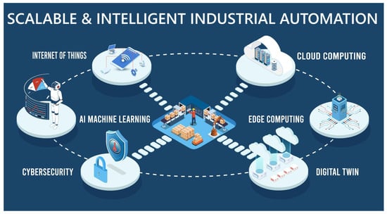
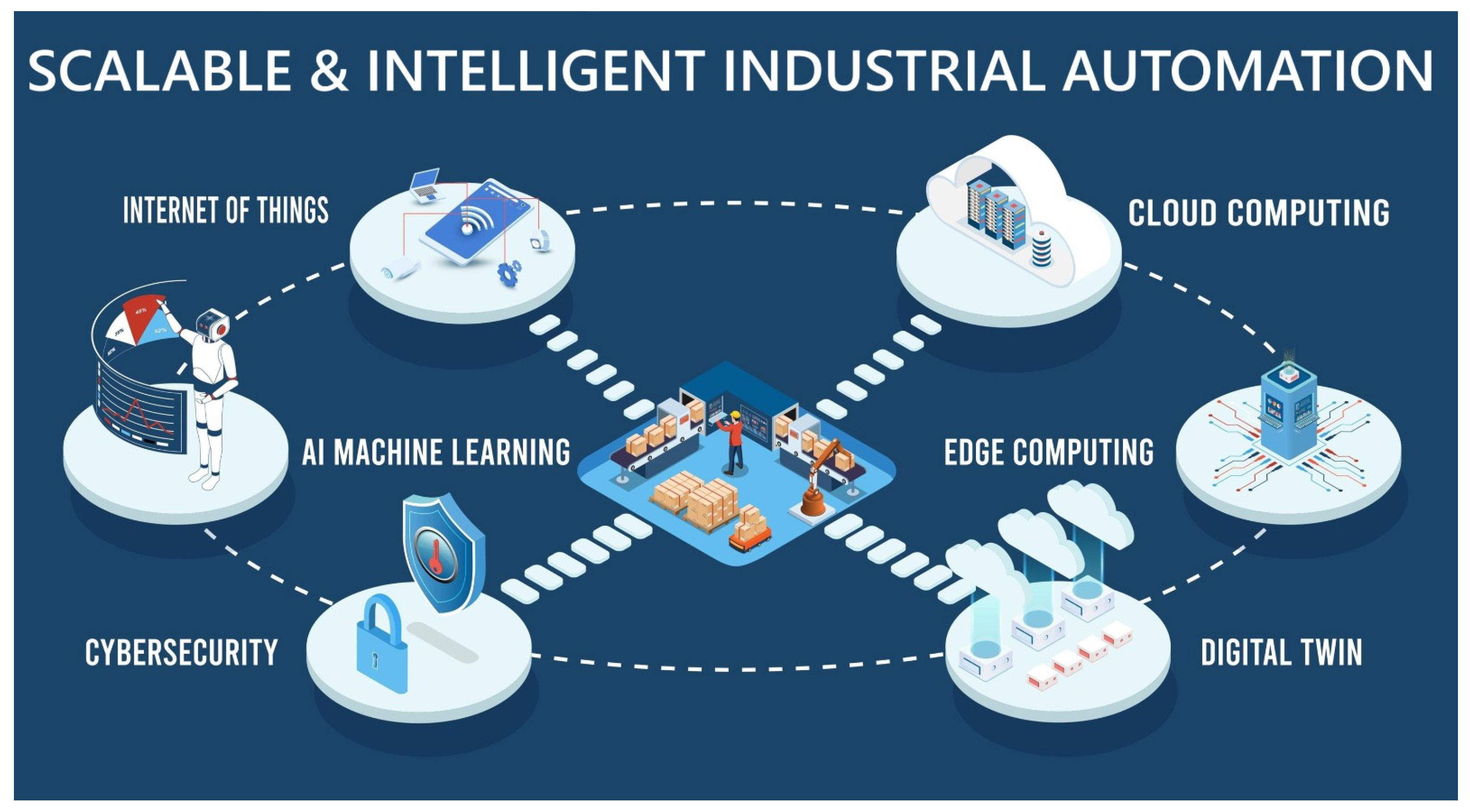
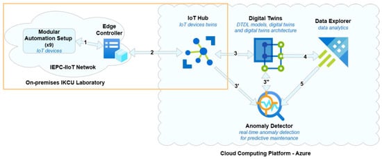
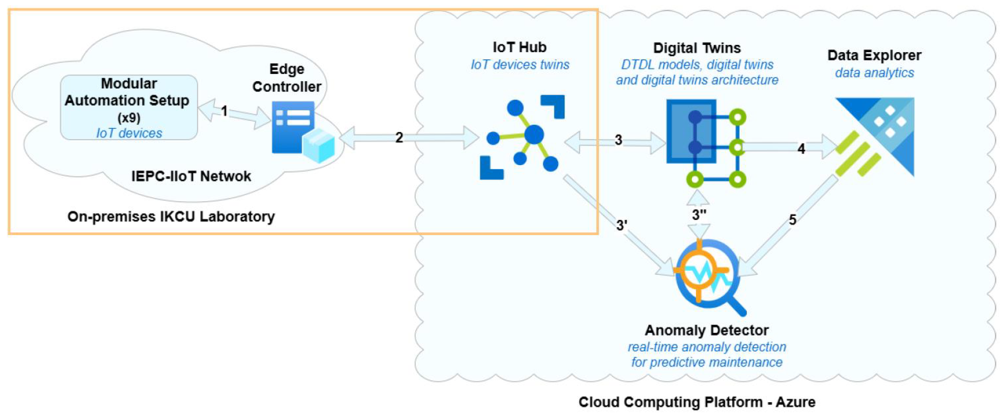
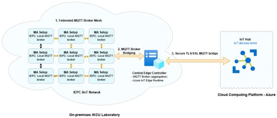
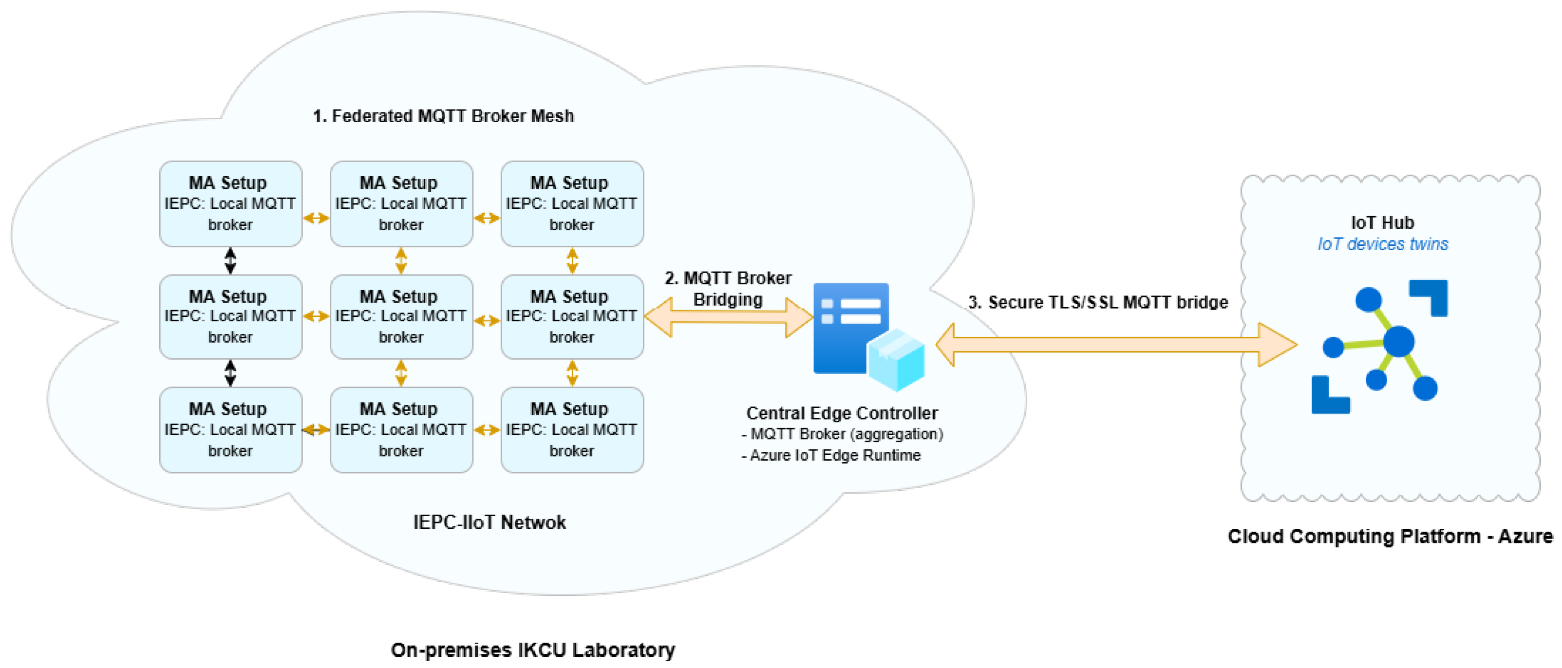
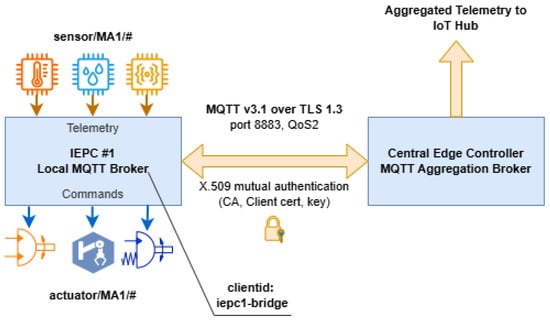
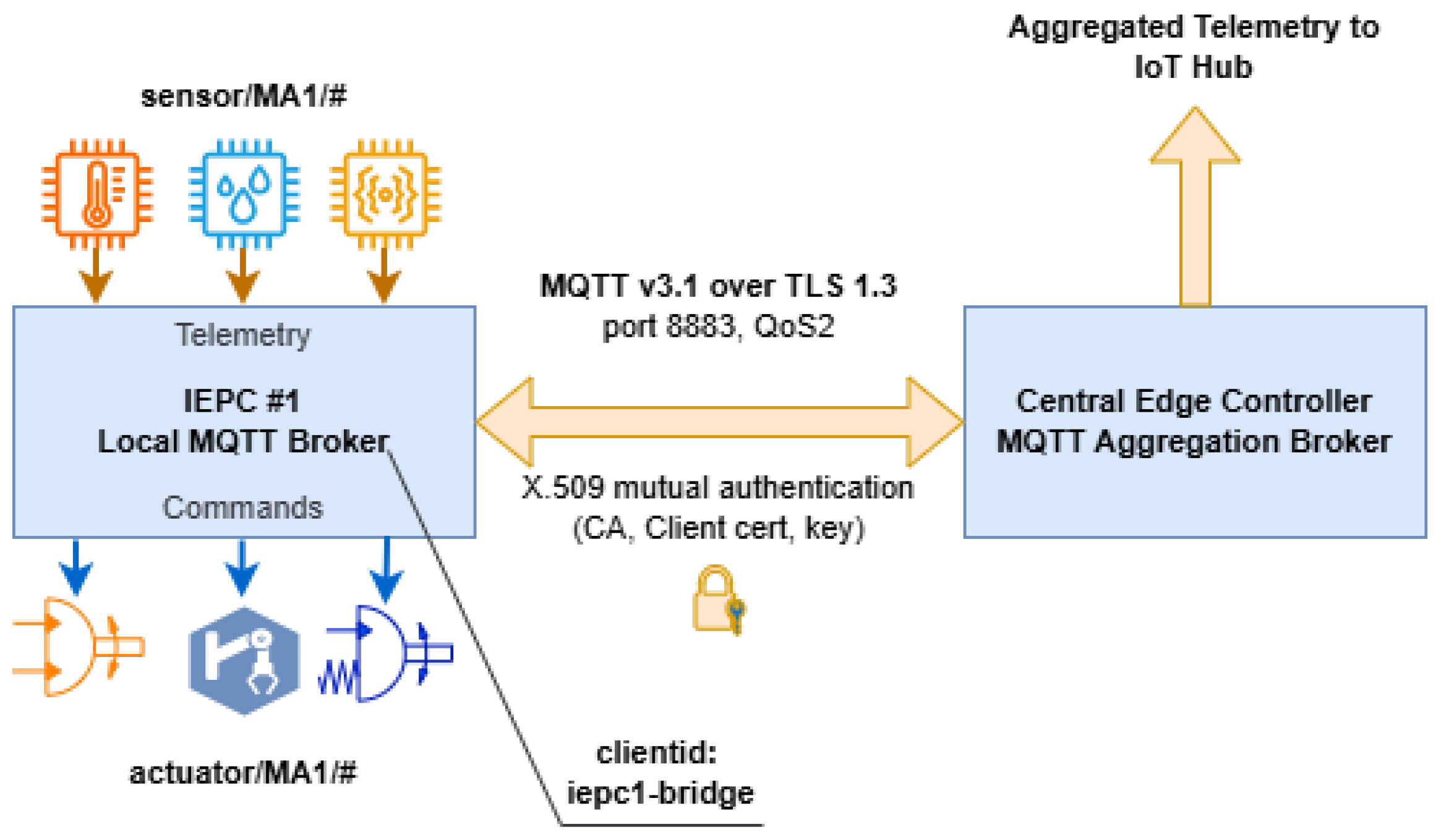
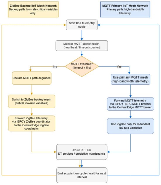
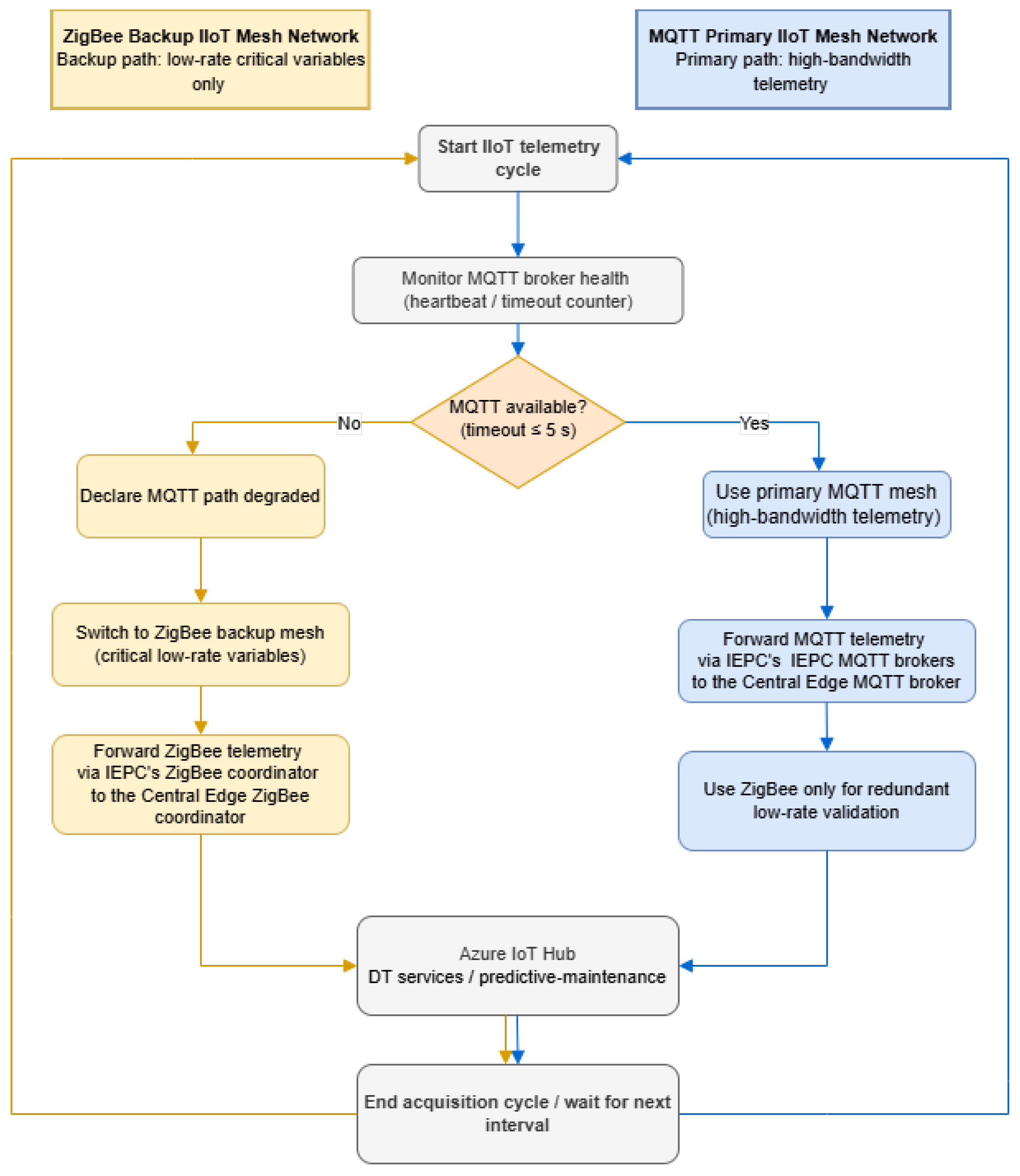
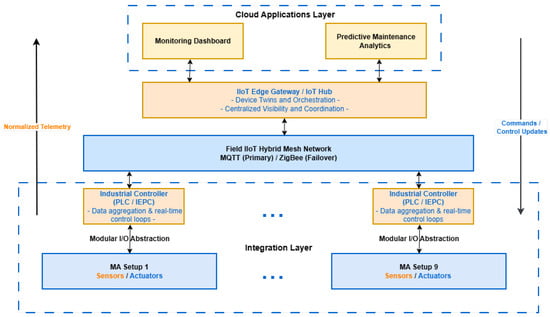
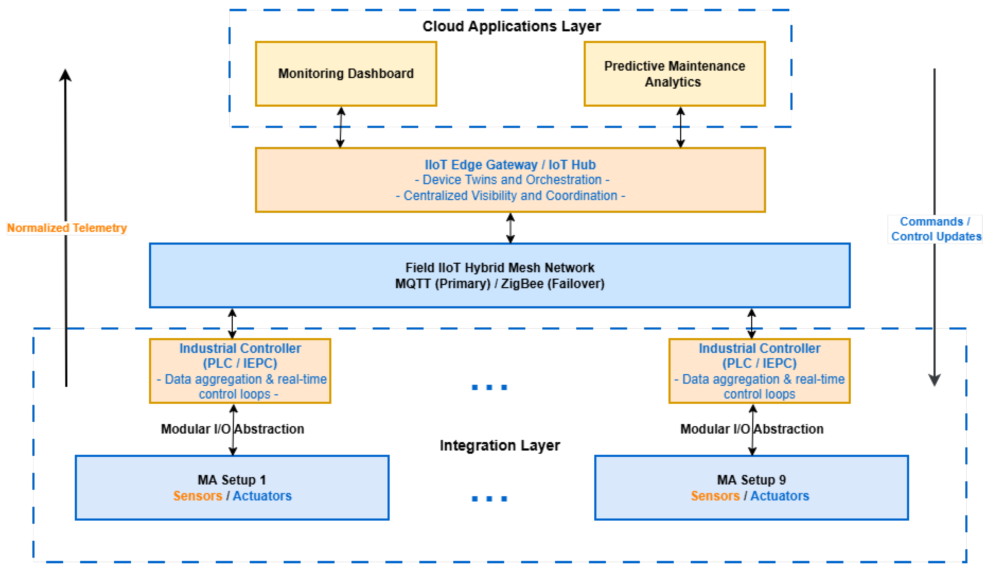
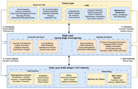
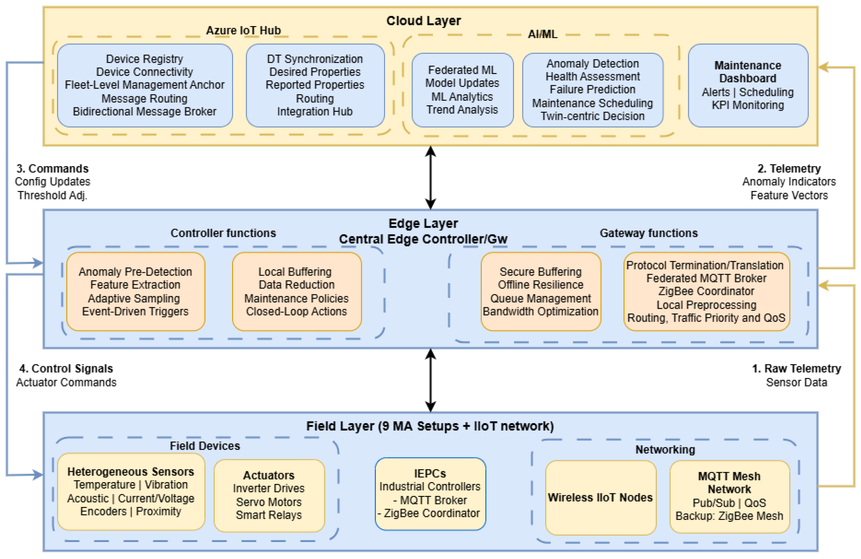
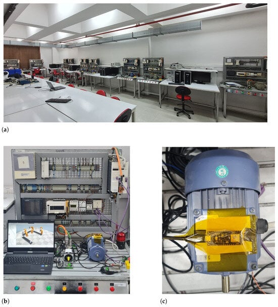
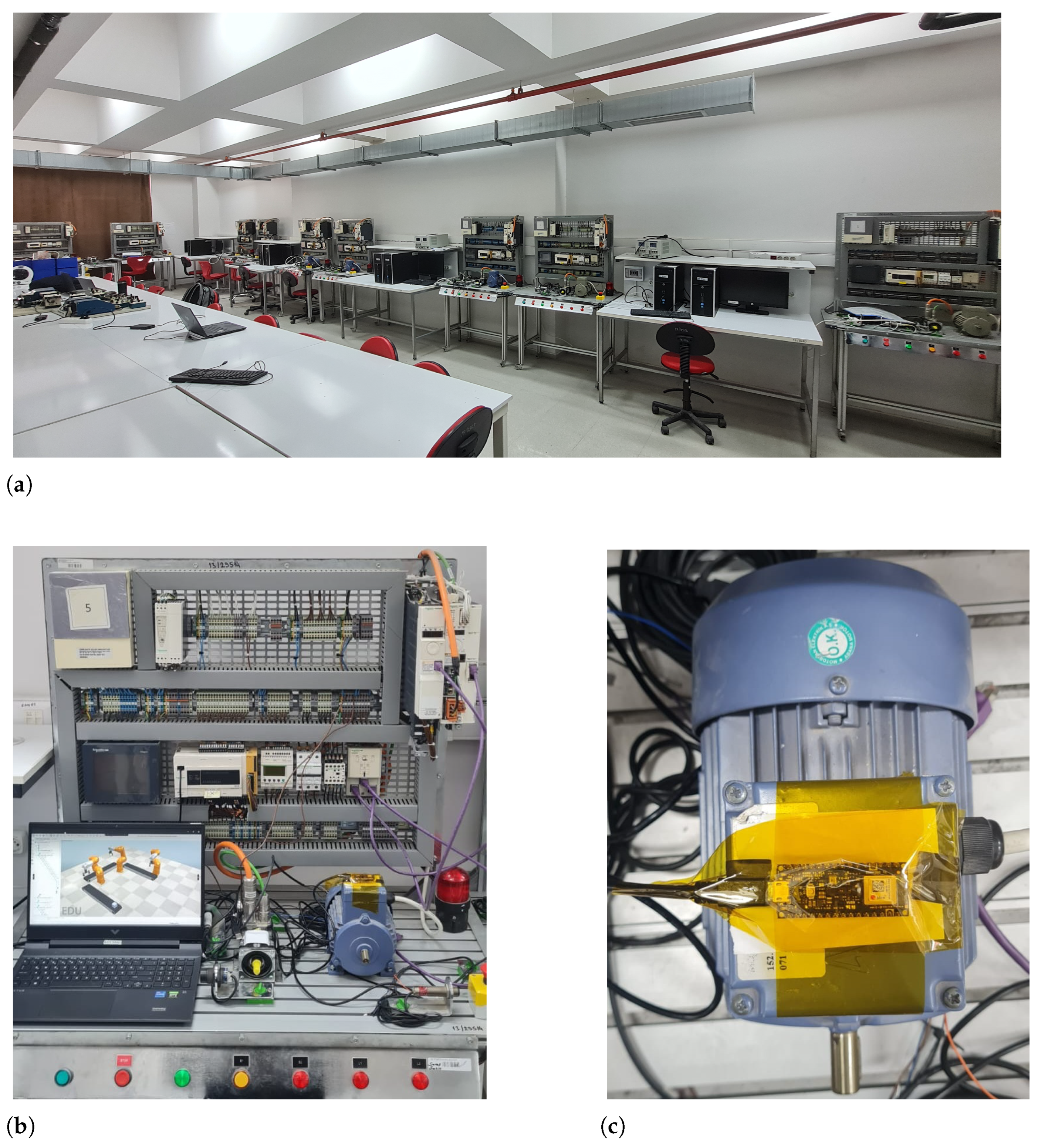
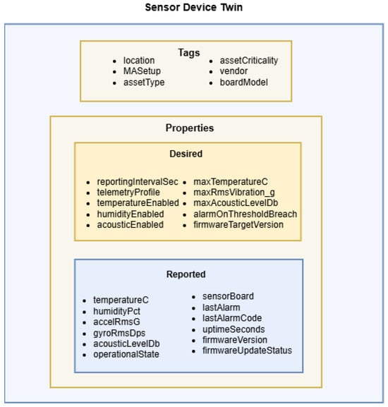
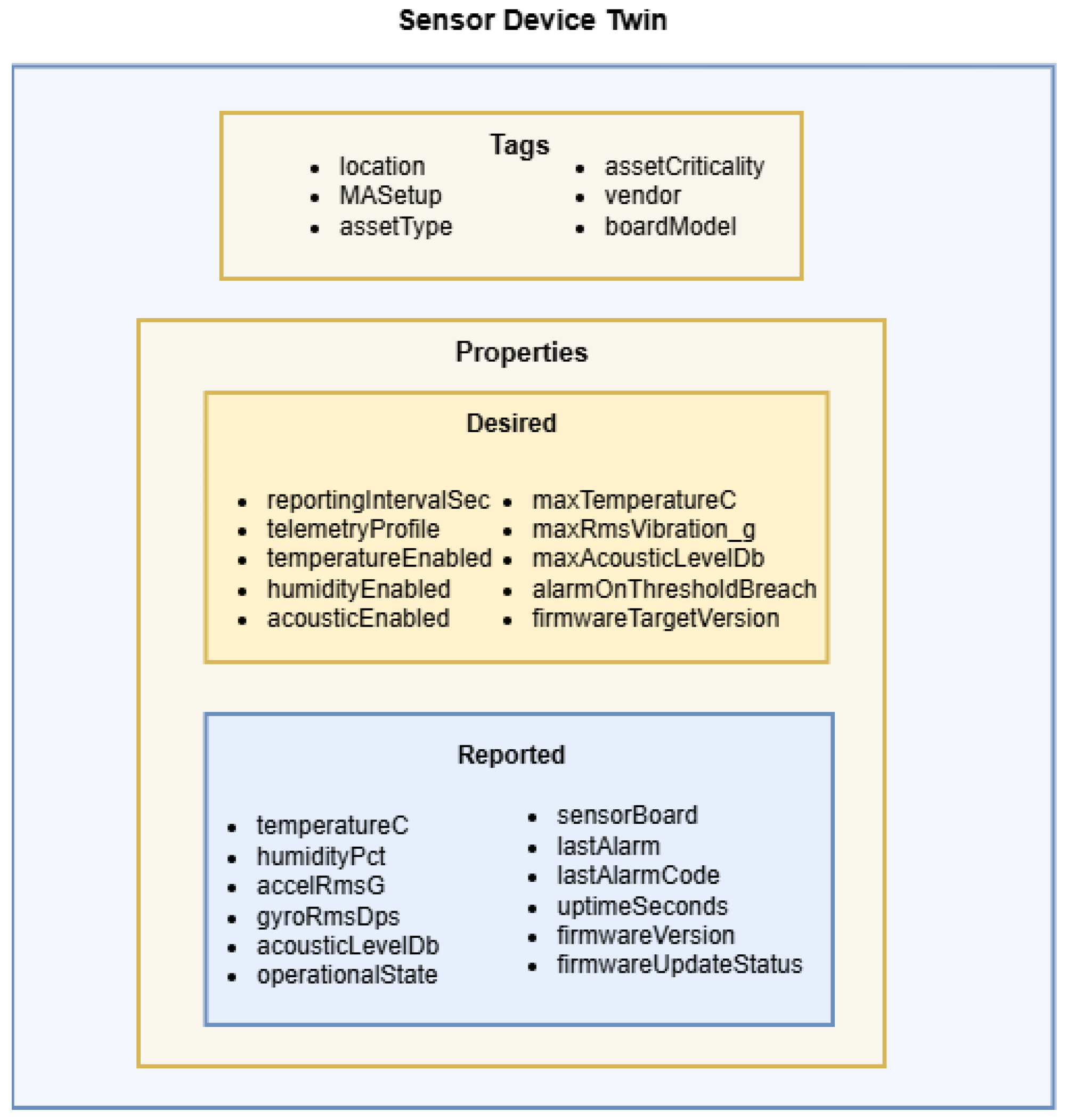
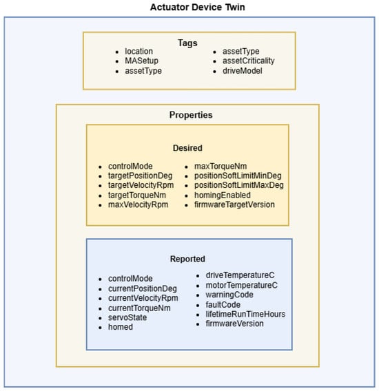
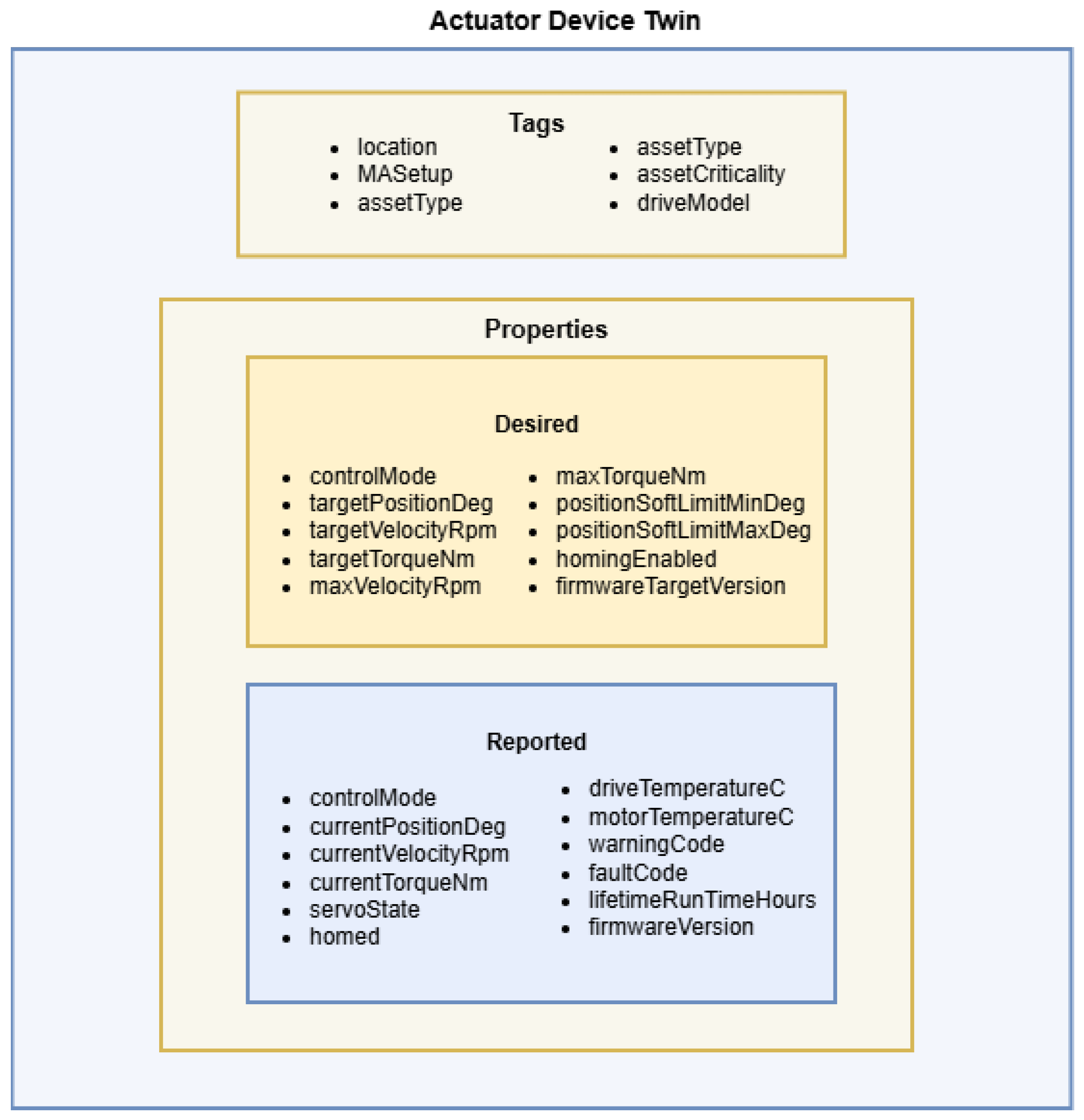
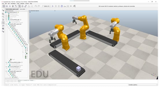
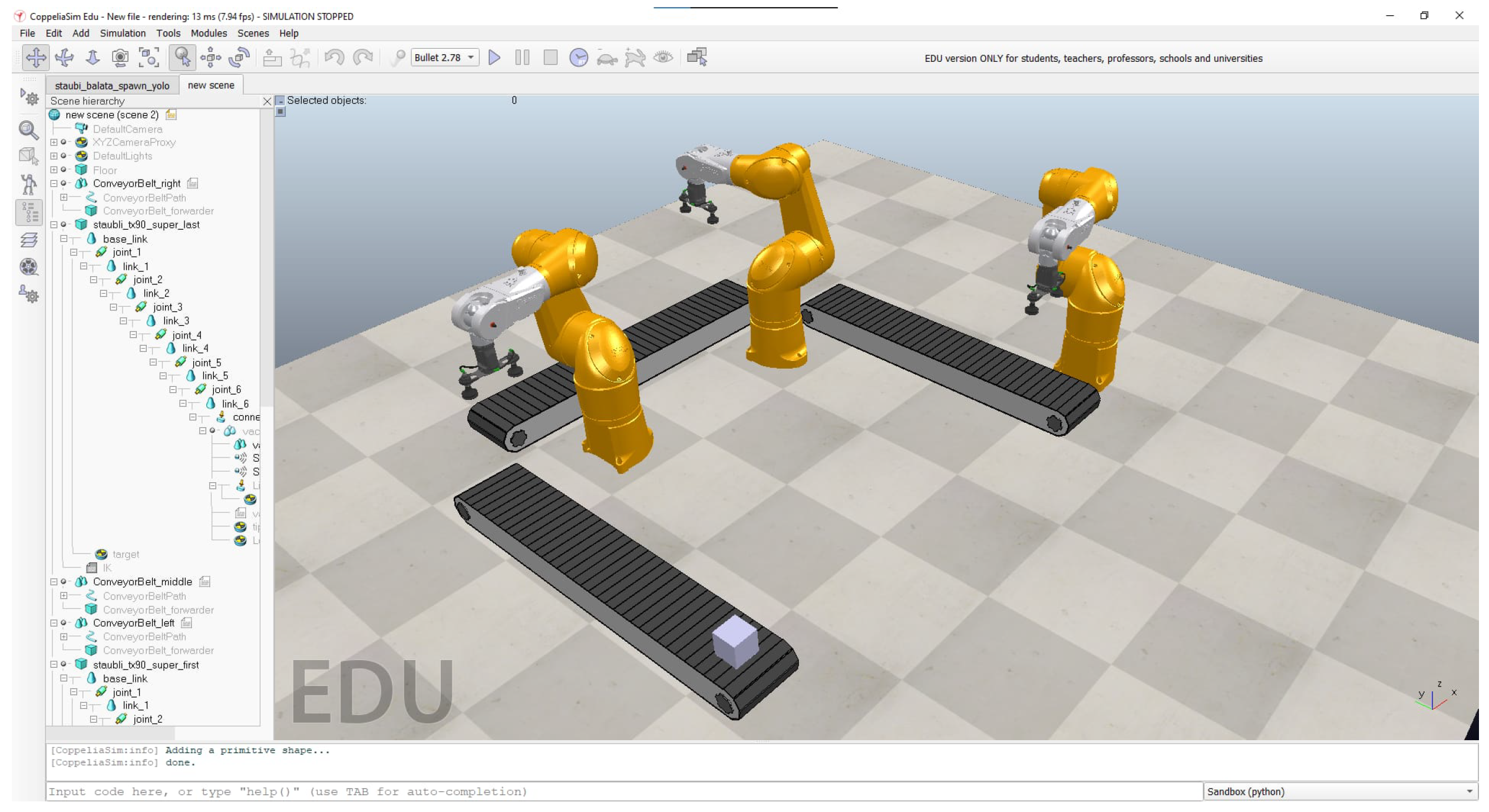
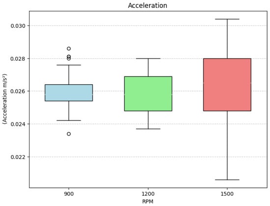
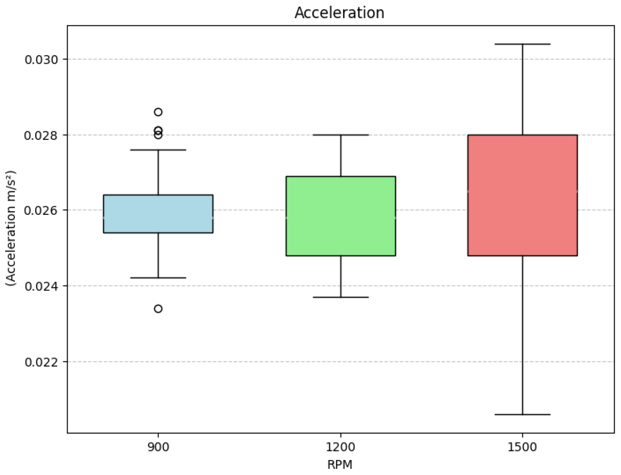
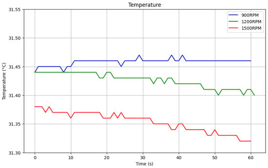
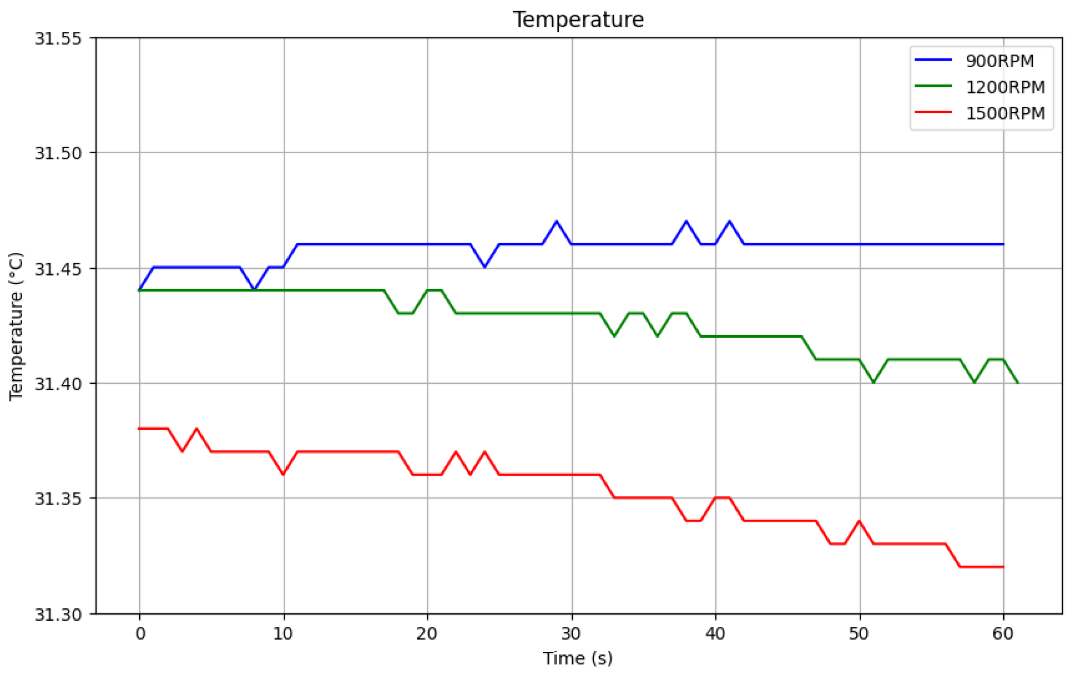
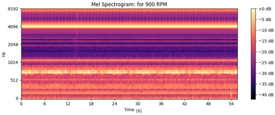
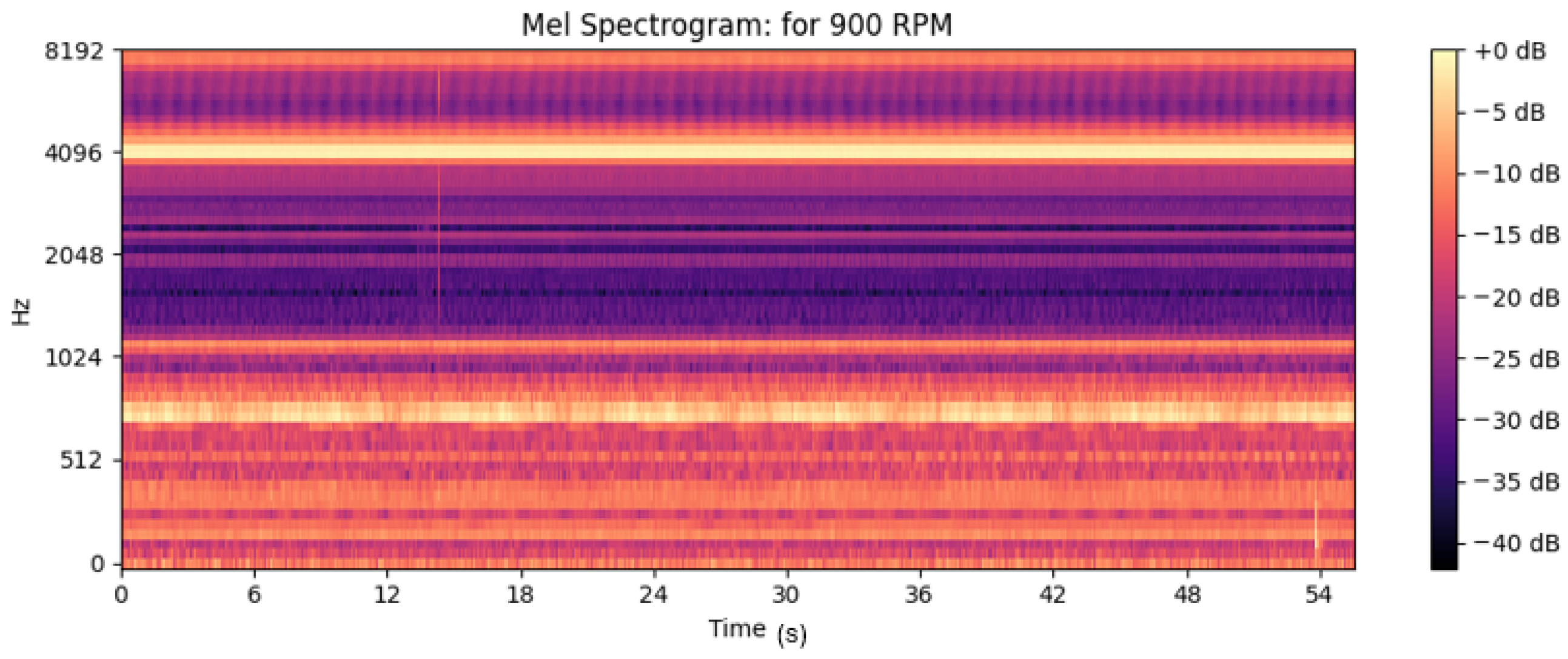
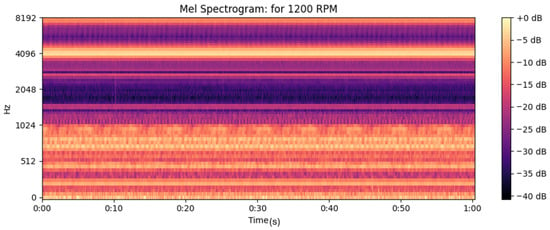
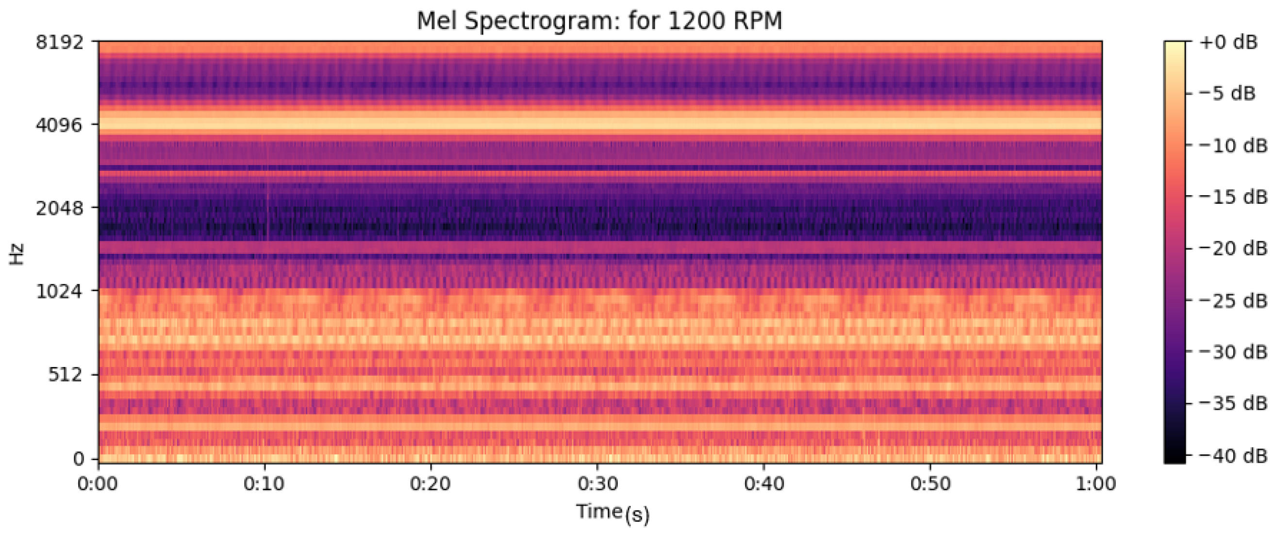
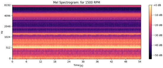
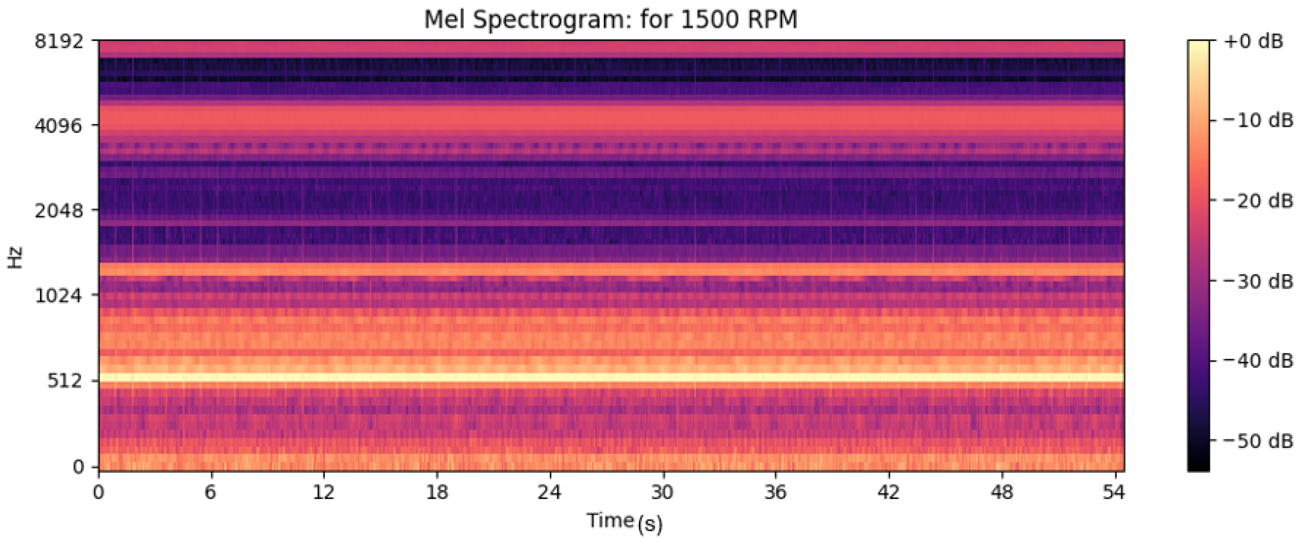

Disclaimer/Publisher’s Note: The statements, opinions and data contained in all publications are solely those of the individual author(s) and contributor(s) and not of MDPI and/or the editor(s). MDPI and/or the editor(s) disclaim responsibility for any injury to people or property resulting from any ideas, methods, instructions or products referred to in the content. |
© 2026 by the authors. Licensee MDPI, Basel, Switzerland. This article is an open access article distributed under the terms and conditions of the Creative Commons Attribution (CC BY) license.