


Abstract
A method for the second-harmonic generation (SHG) in optical fibers by exploiting the third-order nonlinearity under an external electric field is proposed. The analysis begins with the electric polarization vector of the SHG, and the analytical solution for the SHG is presented. When fiber birefringence is neglected, a mode-field matching condition is introduced. The nonlinearity-induced shift in propagation constant is provided based on Gaussian approximation. For a specific case, the power of SHG is calculated. The results show that the SHG power scales quadratically with the nonlinear coefficient. Reducing the effective area of the fiber and increasing the nonlinear coefficient can enhance the SHG power by 1–2 orders of magnitude. Since phase matching strongly affects the SHG process, optimizing the fiber design is crucial. Additionally, the polarization state of SHG is shown to have the same as the equivalent optical field of the injected fundamental wave. This work demonstrates potential for distributed sensing of electric fields and lightning events in high-voltage power grids using optical fibers.
1. Introduction
Second-harmonic generation (SHG) in optical fibers doubles the frequency of incident laser light to achieve wavelength conversion and to produce new wavelengths. This all-fiber approach offers advantages such as high beam quality, high brightness, and a compact design. Consequently, it has been widely used in applications including novel light sources, biomedical imaging, laser processing, and industrial sensing. However, due to the intrinsic rotational symmetry of optical fibers, they exhibit no second-order nonlinearity, which presents a fundamental obstacle to efficient SHG.
In 1986, Japanese scientists U. Osterberg. W. Margulis and others, first observed SHG in quartz fibers. They used UV exposure to break the core’s symmetry, creating a periodic second-order nonlinearity that converted 1064 nm light to 532 nm [1,2]. This breakthrough disproved the long held belief that SHG cannot exist in centrosymmetric quartz fibers. This discovery breaks the traditional cognition that quartz fiber (intrinsic centrosymmetry) cannot produce SHG. After that, the SHG in the optical fiber moves in the direction of the increasing along the optical fiber. In 1988, M. A. Saifi and M. J. Andrejco studied the effect of doping, such as germanium, phosphorus, and fluorine, and the conversion efficiency of 1.5% was achieved [3]. In 1990, E. V. Anoikin et al. studied the effect of γ-ray irradiation on SHG in optical fibers [4] and found that the conversion efficiency of γ-ray-irradiated optical fibers was significantly improved (20 times higher). In 1994, E. M. Dianov et al. found that the fiber doped with Er3+ can easily tune the grating to the mode structure of laser radiation [5]. In the same year, P. G. Kazansky et al. reported that the effective quadratic nonlinearity of polarized germanosilicate fibers is as high as 0.2 pm/v [6]. In 1995, P. G. Kazansky et al. applied a kilovolt DC electric field to the silicate optical fiber at a high temperature (~300 °C). After cooling, it formed a stable and stronger one, up to 1 pm/v, which was 1–2 orders of magnitude higher than that of the UV induction method [7]. In 1999, V. Pruneri et al. made second-order nonlinear grating in D-shaped germanosilicate fiber [8] and obtained a second harmonic with power up to 6.8 mW. Because the efficiency of nonlinear polarization is directly related to phase matching, researchers have put forward many schemes in phase matching. In 2015, C. Daengngam et al. prepared a layer of spatially periodic nonlinear film on quartz fiber [9] for the SHG, which is 15 times stronger than the taper of uniform nonlinear coating. In 2016, A. Elzahaby et al. proposed a frequency-doubling method using the cladding mode as the pump mode [10], and the efficiency was as high as 0.14%. In 2019, T. Cheng et al., using TeO2-Bi2O3-ZnO-Na2O glass as the substrate [11], prepared a step index tellurite fiber with a loss of 0.02 dB/m at 1545 nm, achieving a conversion efficiency of up to 1.15% at 20 mW. In 2022, Xin Zeng et al. proposed using phase doubling to solve a long-term challenge in the power scaling of single-frequency lasers [12]. In the same year, G. Q. Ngo et al. proposed a method of coating MoS2 in fiber cladding to increase the [13]. In 2023, W. A. Gemechu et al. realized the experiment of efficient SHG by cascading multi-segment polarized optical fibers [14]. In 2024, Xiaoyu Chen et al. realized multi-wavelength SHG based on self-phase modulation broadband supercontinuum spectrum by using double-clad high nonlinear fiber and femtosecond laser [15], and the frequency-doubling efficiency reached 1.34 × 10⁻⁴. To sum up, it can be seen that the main goal is still to enhance , whether it is through UV exposure, γ-ray irradiation, doping modification (germanium, phosphorus, fluorine, etc.), thermal polarization, or guiding the light of the core layer to the cladding coated with high material through the tilted grating.
Although the lowest-order nonlinearity in optical fibers is of the third order, and does not directly produce SHG, can the third-order nonlinearity be harnessed to produce SHG under certain conditions? The work in this paper demonstrates that when an external electric field coexists with an optical wave in a fiber, two distinct electro-optic effects emerge. The first is a Kerr-like effect, in which the optical frequency remains unchanged, and the dielectric tensor is proportional to the square of the external electric field. The second effect is the SHG from the fundamental wave under the external field, where the amplitude and polarization state of the SHG are proportional to the strength of the applied electric field. Formally, this latter effect can be categorized as a first-order electro-optic interaction in its functional dependence. However, it is fundamentally distinct from the conventional Pockels effect and cannot be simply classified as either a pure first- or second-order electro-optic phenomenon.
The SHG via the third-order nonlinearity of optical fibers under an external electric field holds potential for distributed electric field sensing in power grids. It is well known that excessively high local electric fields within power cables or high-voltage transformer windings can induce partial discharge, leading to localized damage. Consequently, distributed electric field measurement is a critical challenge in power systems. Conventional sensing techniques, based on crystals such as lithium niobate or bismuth germanate, are inherently limited to point measurements. While distributed sensing currently relies primarily on optical backscattering techniques in fibers, the question of whether fiber parameters modified by an electric field can be exploited for truly distributed electric field mapping remains an open and active topic in the industry.
2. The Electric Polarization Vector of the SHG by Third-Order Nonlinearity Under an External Electric Field
The nonlinearity of optical fibers mainly originates from the third-order susceptibility . At this time, the nonlinear polarization can be written as,
where represents the dielectric constant in vacuum, and denotes the first-order electric susceptibility of the isotropic fiber. For the nonlinear component in Formula (1), considering the light is transverse wave, it is not difficult to prove
where is the component of the third-order nonlinear susceptibility tensor.
The polarization vector can be divided into a linear part and a nonlinear part, , and considering that the linear part can be rewritten as the dielectric constant
since , when the medium is isotropic and the loss is very small, and is the refractive index.
Hereinafter, due to the frequent coexistence of quantities related to fundamental frequency light and SHG light in this article, for ease of distinction, subscript 0 is used to denote quantities related to fundamental frequency light, while subscript 2 is used to denote quantities related to SHG light. Considering the fundamental frequency light injected into the fiber as
where is the angular frequency of the fundamental frequency light; and are the amplitudes of the two polarization components of the fundamental frequency light at a certain local time, ; and , , and are the phase at a certain local time and the transmission constant of the two polarization components, respectively. The external electric field usually consists of three components, but since there is no longitudinal component in the light field, the longitudinal electric field has no effect on the light field. Only the transverse electric field needs to be considered. In this case, the external electric field is also written as two polarization components, . Due to the slow variation rate of the external electric field, much lower than the optical frequency, it can be regarded as a direct current. When the light field interacts with an external electric field, the electric field strength in the optical fiber follows the superposition principle,
Substituting Equation (5) into Equation (2), after calculation, the fundamental frequency term, SHG term, and third harmonic term can be obtained. Due to the low power of the newly generated SHG light, it will not produce nonlinearity again. Therefore, it can be processed according to a linear system (positive frequency and negative frequency are processed separately). To ensure that the transmission of light follows the positive direction of z, and for the fiber with low birefringence , the negative frequency polarization vector of the SHG is taken as , and
According to Equation (3), the electric displacement vector of the SHG can be calculated as
where is the refractive index of the material when . Since both and are functions of the horizontal axis , on the other hand, the two polarization components are not the same, resulting in anisotropy.
3. The Wave Equation Satisfied by SHG and Its Solutions
In optical fibers there is the Helmholtz equation
For the SHG, considering Equation (7), , one can get that
where is the wave number of the SHG in vacuum. Due to the weak power of SHG by the third-order nonlinearity of optical fibers, the SHG light will not generate nonlinearity again. Due to being very small (on the order of 10−22 V2/m2), , it can be inferred that , so that
Equation (10) is the wave equation satisfied by SHG, which is a non-homogeneous active equation, including a homogeneous equation on its left and there is an active term on its right. Therefore, in addition to including horizontal fields and a wave propagation term , their amplitudes should also vary accordingly. So, it sets up that
where is the amplitude distribution of the SHG along the longitudinal direction. Note that it may be a complex number, including the variation in amplitude and phase. It should be noted that due to the different active terms in the two polarization directions, the two polarization components of are different, that is . is the transverse distribution (mode field) of the SHG, and it does not vary with the polarization direction for low birefringence fibers; the transmission constant is that when only the light of the second-harmonic wave is injected, which is not the transmission constant of the SHG generated by nonlinearity. As will be seen later, the transmission constant of SHG light generated by fiber nonlinearity is not equal to the transmission constant of injecting light of the second-harmonic wave alone.
Consider the Laplace operator of the transverse component in the cylindrical coordinate system, substituting it into Equation (10), and can be obtained by
It is just the wave equation satisfied by the SHG caused by the external electric field. Solving Equation (12) is a complex process. Referring to Appendix A, there are two situations:
(i) If , realizing phase matching,
(ii) If , considering the actual use of optical fibers, , and taking into account , it can be concluded that
Finally, according to Equation (19), we obtain
(i) When phase matching is achieved,
(ii) In the case of the quasi-phase matching,
In Equation (16), let . Then, Equation (15) is obtained, indicating that Equation (16) can be considered as a general formula. It is known that the polarization state of the SHG caused by the external electric field is consistent with . The remaining question is how to find , , and . They correspond to three equations, respectively.
In these formulas, represent the refractive index distribution for fundamental frequency, second harmonic, and under an external electric field, and and have been obtained in Appendix B; and , , and represent the mode fields of fundamental frequency, second harmonic, and SHG under the external electric field, respectively; represent the transmission constants corresponding to the three situations.
4. Simulation Calculation for Application Scenarios
For the commonly used single-mode fiber, SMF-28 has the following main parameters: fiber core radius , relative refractive index difference , and at 1.55 wavelength. The Sellmeier formula is used
By calculating , , and separately, and , it can be concluded that the condition is satisfied. Using Gaussian approximation to solve Equations (17)–(20), we obtained , , and , respectively. Clearly, there is a phase mismatch . Although it is much smaller than , it is still on the order of 105 m−1. To achieve quasi-phase matching, it is necessary to carefully design the structure of the optical fiber and control the wavelength used.
According to expression (16) of the light field of SHG, we calculate the power of the SHG by injecting different fundamental frequency light powers. Under the assumption of Gaussian distribution, the optical power of each wavelength is
where subscripts correspond to the fundamental frequency and SHG. and , and , and , and and represent the optical power, mode spot radius, refractive index, and maximum electric field strength in the fiber core corresponding to the two wavelengths, respectively. By comparing the two equations and combining them with Equation (16), the following relationship can be derived between the two powers
When the input polarization state is not linear polarization, the expression of is very complex. To simplify, we only consider the simple case where the input polarization is linear and the direction of the external electric field is consistent with the direction of the polarization state. In this case,
Rewrite the third-order nonlinear susceptibility into nonlinear coefficients to obtain
where is the wave impedance in the vacuum. Equation (24) is a formula used to calculate the power of the SHG under the premise of injecting a single linear polarization state and applying an electric field in the same direction as the linear polarization.
Using Equation (24) for lightning scenarios, we assume the following parameters:
(i) For the high nonlinear fiber (HNLF) NL1050-Zero-2 type of NKT Corporation (Birkerød, Denmark) in Japan [16], W−1 m−1; and for standard single-mode optical fiber ;
(ii) The injected fundamental frequency light is continuous, with a power ;
(iii) The external electric field is the lightning field, uniformly distributed, with a magnitude close to the breakdown field ; ;
(iv) For high nonlinear fiber (HNLF), its mode-field diameter is (The diameter when the power drops down to 13%), and cross-sectional area are given in the manual. For the single-mode fiber (SMF), the effective cross-section is ;
(v) The refractive index of SHG is calculated using the Sellmeier formula as ;
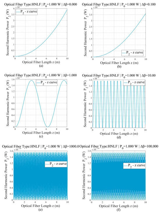
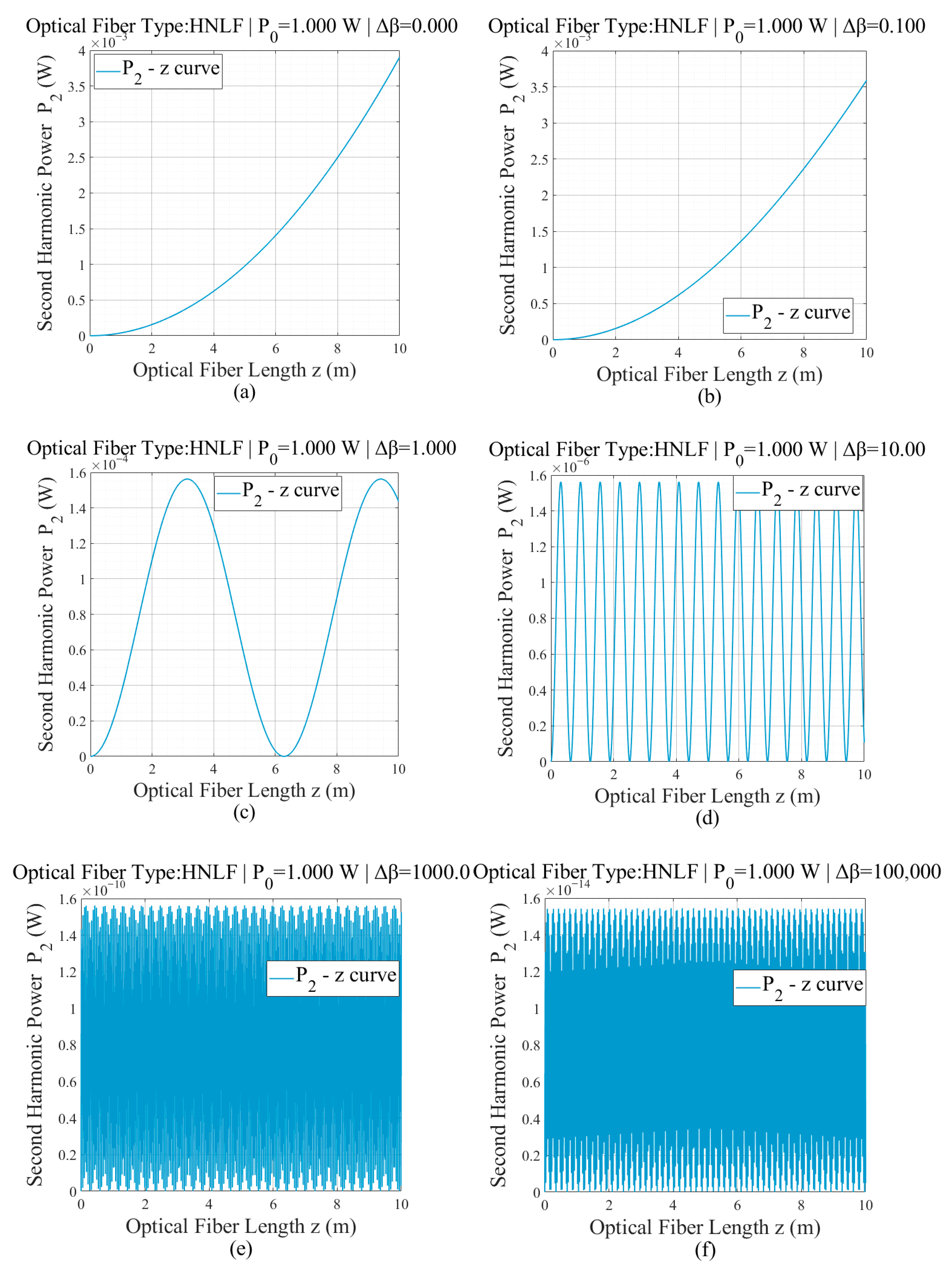
Using phase mismatch as a parameter, calculate the corresponding curves from 0, 0.1, 1, 10, 100, 1000, and 105 (m−1). Calculate the corresponding power curves separately, as following:
The calculation results for NL1050-Zero-2 type HNLF are shown in Figure 1. As shown in the figure, when the same external electric field is applied for a length of 10 m, the power of the SHG decreases rapidly with the increase in phase mismatch. During phase matching, the SHG power can reach the order of mW; however, at , the average power of the SHG was only on the order of fW. Therefore, phase matching is crucial for SHG.
Figure 1.
Relationship between the power of SHG and the length z of the external electric field in HNLF under different phase mismatches
(m−1) in a SMF. In the Figure: (a) , (b) , (c) , (d) , (e) , and (f) .
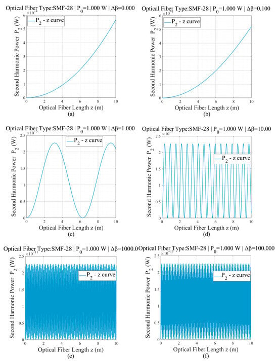
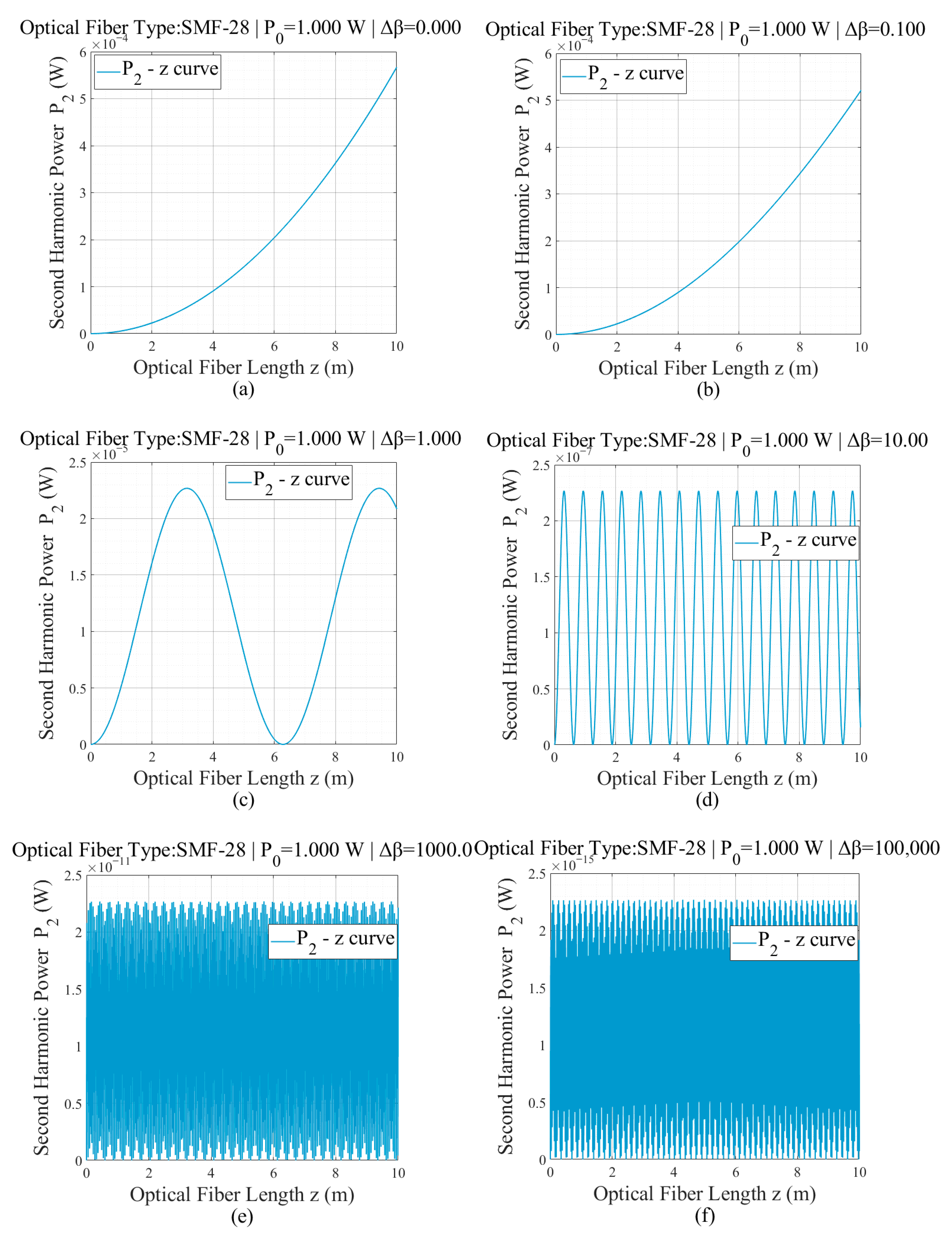
For the ordinary single-mode fiber SMF-28, the calculation results are shown in Figure 2. The pattern presented is the same as that of HNLF, but the overall output power decreases by 1–2 orders of magnitude.
Figure 2.
Relationship between the detected power of SHG and the length z of the external electric field under different phase mismatches (m−1) in a SMF. In the Figure: (a) , (b) , (c) , (d) , (e) , and (f) .
5. Conclusions
Compared with previous studies that obtained SHG by means of enhancement for , this paper proposes a different method of the SHG under external electric field without breaking the intrinsic center symmetry of the fiber. Once phase matching is achieved, the SHG can be obtained. In the presence of an external electric field, the third-order nonlinearity of an optical fiber can lead to second-harmonic generation (SHG). This paper presents a detailed theoretical analysis of the SHG mechanism, its key parameters, and its relationship with the external electric field. First, the second-harmonic polarization vector induced in the fiber under an external electric field is derived. Subsequently, using the Gaussian approximation method, an analytical expression for the electric field strength of the fundamental mode of the SHG is obtained. Finally, the relationship between the power of the SHG and the lightning electric field is discussed.
The analytical results indicate that the nonlinear coefficient of conventional optical fibers is too small, resulting in very weak SHG. By reducing the effective cross-sectional area of the fiber to enhance the nonlinear coefficient, the SHG power can be increased by 1 to 2 orders of magnitude. Furthermore, phase matching has a more pronounced impact on SHG efficiency. For every order of magnitude reduction in phase mismatch, the SHG power increases by two orders of magnitude. When perfect phase matching is achieved, the generated SHG power becomes proportional to the square of the fiber length. Therefore, optimizing the fiber structure to achieve phase matching is crucial. In addition, the polarization state of the SHG is identical to that of the equivalent optical field of the injected fundamental frequency light. This study demonstrates the potential application value of using optical fibers for measuring the distribution of lightning electric fields or high-voltage electric fields in power grids.
Author Contributions
Conceptualization, C.W.; Methodology, L.L.; Software, Z.H. and L.X.; Investigation, L.L. and C.W.; Data curation, Z.H. and L.X.; Writing—original draft, L.L. and K.W. All authors have read and agreed to the published version of the manuscript.
Funding
This research received no external funding.
Institutional Review Board Statement
Not applicable.
Informed Consent Statement
Not applicable.
Data Availability Statement
The original contributions presented in the study are included in the article, further inquiries can be directed to the corresponding author.
Conflicts of Interest
The authors declare no conflict of interest.
Appendix A. Solutions to the Wave Equation
In the wave Equation (12) we cannot yet consider as a slow variable, so the term cannot be ignored. To solve Equation (12), it is necessary to first solve the homogeneous Equation (A1):
where is the general solution of the homogeneous Equation (A1), but is the general solution that satisfies Equation (12); this is the mode field, which is not affected by the active term. This equation can be rewritten into two independent equations using the method of separating variables,
In Equations (A2) and (A3), is a constant introduced for the separation of variables method; subsequent calculations indicate that for actual optical fibers , so it can be assumed that . Equation (A2) indicates that due to the effect of an external electric field, the refractive index of the optical fiber has changed. If let ; then, . In this way, in the original equation will also be changed; let , and the original equation will be rewritten as
Therefore, Equation (A3) also needs to be modified accordingly; let , and substitute it into (A1) and simplify to obtain
For Equation (A5), it can be solved . At the position , there is no SHG, so we obtain
Returning to the non-homogeneous Equation (12), substitute (A6) into (12) and simplify to obtain
Note that is only related to and not to z. Next, we use the method of constant variation to find the specific solution of Equation (A7), and assuming that and at the position , the solution will be obtained
To calculate the integral of Equation (A8), two scenarios are considered:
(i) If , the phase matching is achieved. Then, Equation (A8) is transformed into
(ii) If , we can obtain
Equations (A9) and (A10) correspond to Equations (15) and (16) in the main text, respectively.
Appendix B. Using Mode-Spot Matching to Calculate the Change in Refractive Index
In the main text, is the key to determining the transmission constant of the SHG. This appendix studies how to use the mode-spot matching condition to obtain it.
In Equation (A7), there is a constant vector defined by the ratio , which must be independent of coordinates. For low birefringence fibers, the fundamental mode field is polarization-independent; its distribution is independent of the azimuth angle and can be written as , where is the mode spot radius of the fundamental mode, and is the electric field strength at the center of the fundamental mode and is a known quantity. From Equation (8), it can be inferred that , where represents the value of the equivalent electric field strength at the center of the optical fiber. For the SHG, the mode field of its fundamental mode is also a Gaussian function, , where is the mode spot radius of the fundamental mode of the SHG; it is possible to set (because it can be made 1 by changing the size of ), so that
To make it independent of coordinates, it must be , under Gaussian approximation this is called the mode spot matching condition that the fundamental and SHG need to satisfy, and , where is the radius of the fiber core. and () represent the mode spot radius of the fundamental frequency and SHG, and their corresponding normalized frequencies, respectively. From this, it can be concluded that . Due to , after simple calculations, it can be concluded that . Assuming that the relative refractive index difference does not vary significantly with wavelength, then
Using the Sellmeier Formula (20), the can be calculated; therefore, the Formula (A12) can be fully calculated.
References
- Osterberg, U.; Margulis, W. Dye laser pumped by Nd:YAG laser pulses frequency doubled in a glass optical fiber. Opt. Lett. 1986, 11, 516. [Google Scholar] [CrossRef] [Scilit] [PubMed]
- Osterberg, U.; Margulis, W. Experimental studies on efficient frequency doubling in glass optical fibers. Opt. Lett. 1987, 12, 57. [Google Scholar] [CrossRef] [Scilit] [PubMed]
- Saifi, M.A.; Andrejco, M.J. Second-harmonic generation in single-mode and multimode fibers. Opt. Lett. 1988, 13, 773. [Google Scholar] [CrossRef] [Scilit] [PubMed]
- Anoikin, E.V.; Dianov, E.M.; Kazansky, P.G.; Stepanov, D.Y. Photoinduced second-harmonic generation in gamma-ray-irradiated optical fiber. Opt. Lett. 1990, 15, 834. [Google Scholar] [CrossRef] [Scilit] [PubMed]
- Dianov, E.M.; Kornienko, L.S.; Rybaltovsky, A.O.; Chernov, P.V.; Yatsenko, Y.P. Photoinduced SHG in fibers doped with rare-earth ions. Opt. Lett. 1994, 19, 439. [Google Scholar] [CrossRef] [Scilit] [PubMed]
- Kazansky, P.G.; Dong, L.; Russell, P.S.J. High second-order nonlinearities in poled silicate fibers. Opt. Lett. 1994, 19, 701. [Google Scholar] [CrossRef] [Scilit] [PubMed]
- Kazansky, P.G.; Pruneri, V.; Russell, P.S.J. Blue-light generation by quasi-phase-matched frequency doubling in thermally poled optical fibers. Opt. Lett. 1995, 20, 843. [Google Scholar] [CrossRef] [Scilit] [PubMed]
- Pruneri, V.; Bonfrate, G.; Kazansky, P.G.; Richardson, D.J.; Broderick, N.G.; de Sandro, J.P.; Simonneau, C.; Vidakovic, P.; Levenson, J.A. Greater than 20%-efficient frequency doubling of 1532-nm nanosecond pulses in quasi-phase-matched germanosilicate optical fibers. Opt. Lett. 1999, 24, 208. [Google Scholar] [CrossRef] [Scilit] [PubMed]
- Daengngam, C.; Kandas, I.; Ashry, I.; Wang, A. Fabrication and characterization of periodically patterned silica fiber structures for enhanced second-order nonlinearity. Opt. Express 2015, 23, 8113. [Google Scholar] [CrossRef] [Scilit] [PubMed]
- Elzahaby, E.A.; Kandas, I.; Aly, M.H. Second harmonic generation in thin optical fibers via cladding modes. Opt. Express 2016, 24, 261599. [Google Scholar] [CrossRef] [Scilit]
- Cheng, T.; Xiao, Y.; Li, S.; Yan, X.; Zhang, X.; Suzuki, T.; Ohishi, Y. Highly efficient second-harmonic generation in a tellurite optical fiber. Opt. Lett. 2019, 44, 4686. [Google Scholar] [CrossRef] [Scilit]
- Zeng, X.; Cui, S.; Cheng, X.; Feng, Y. Spectral compression by phase doubling in second harmonic generation. Opt. Lett. 2022, 47, 15. [Google Scholar] [CrossRef] [Scilit]
- Ngo, G.Q.; Najafidehaghani, E.; Gan, Z.; Khazaee, S.; Siems, M.P.; George, A.; Schartner, E.P.; Nolte, S.; Ebendorff-Heidepriem, H.; Pertsch, T. In-fibre second-harmonic generation with embedded two-dimensional materials. Nat. Photonics 2022, 16, 769. [Google Scholar] [CrossRef] [Scilit]
- Gemechu, W.A.; Minoni, U.; Modotto, D.; Tonello, A.; Couderc, V. Efficient SHG through cascaded optically poled fibers. Opt. Lett. 2023, 48, 1. [Google Scholar] [CrossRef] [Scilit] [PubMed]
- Chen, X.; Zhou, X.; Yan, X.; Zhang, X.; Suzuki, T.; Ohishi, Y.; Cheng, T. Multi-wavelength second-harmonic generation in a double-clad high nonlinear fiber induced by multiple phase-matching. Opt. Lett. 2024, 49, 3190. [Google Scholar] [CrossRef] [Scilit] [PubMed]
- KTN Photonics Co. Technical Manual of NL1050-Zero-2 Fiber. 2025. Available online: https://www.nktphotonics.com/products/optical-fibers-and-modules/nonlinear-photonic-crystal-fibers/ (accessed on 18 January 2026).
Disclaimer/Publisher’s Note: The statements, opinions and data contained in all publications are solely those of the individual author(s) and contributor(s) and not of MDPI and/or the editor(s). MDPI and/or the editor(s) disclaim responsibility for any injury to people or property resulting from any ideas, methods, instructions or products referred to in the content. |
© 2026 by the authors. Licensee MDPI, Basel, Switzerland. This article is an open access article distributed under the terms and conditions of the Creative Commons Attribution (CC BY) license.