


Abstract
Thin-walled parts are widely used in the automotive manufacturing industry due to their lightweight characteristics and high structural efficiency. However, it is difficult to accurately measure machining errors in key regions due to the feature deformation. To improve the online measurement accuracy of complex thin-walled parts, a machining error measurement approach based on multi-constraint point cloud registration is proposed. To address the low overlap and complex geometric features among multi-segment measured point clouds, a point cloud stitching method based on hole boundary features is developed to acquire complete measured point clouds. Meanwhile, a point cloud surface extraction method based on normal neighborhood searching is developed to acquire model point clouds. Since different regions of thin-walled parts require different geometric tolerances, a registration model integrating multiple locating and assembly constraints is proposed to satisfy the requirements for optimal point cloud registration. A measurement system composed of a line-structured light sensor and a six-axis robotic arm is developed to validate the proposed method. Experimental results show that the proposed approach reduces the overall dimensional error of point cloud stitching by approximately 70–86% and decreases the point number deviation between upper and lower surfaces by more than 98%. Furthermore, the measurement accuracy in locating holes and key assembly regions is improved to 0.05 mm and 2 mm, representing improvements of approximately 96.3% and 23.9% compared with registration methods without multi-constraint conditions, and approximately 95.3% and 14.5% compared with commonly used multi-constraint registration methods.
1. Introduction
In the automotive manufacturing industry, thin-walled parts such as front wheel housings offer advantages including high structural efficiency, low density, and high material utilization, which effectively reduce vehicle weight and improve fuel economy. However, these thin-walled parts are prone to feature deformation during the manufacturing process [1]. At present, the inspection of thin-walled parts mainly relies on manual measurement using dedicated fixtures, which involves high measurement costs and fails to satisfy the requirements for inspection flexibility and efficiency under the increasingly prevalent small-batch and multi-variant production modes in the automotive industry [2].
In recent years, non-contact three-dimensional laser measurement techniques have enabled accurate acquisition of three-dimensional surface coordinates by computing the time of flight or phase shift of laser signals [3]. Owing to the high aspect ratio characteristics of thin-walled parts, where the thickness is much smaller than the length and width, geometric surface information can be effectively acquired through surface scanning [4], thereby providing a reliable data basis for the measurement and analysis of machining errors.
After acquiring the geometric surface information of thin-walled parts, existing research commonly utilized point cloud registration-based methods for machining error measurement. By minimizing the fitting error between the measured point cloud and the reference model point cloud, this approach enables accurate evaluation of the global shape deviation of thin-walled parts [5,6]. However, local regions of thin-walled parts, such as assembly holes, boundary bending areas, and locating datum surfaces, are usually subject to more stringent geometric tolerance requirements [7,8]. Therefore, when applying point cloud registration methods to machining error measurement of thin-walled parts, it is necessary not only to quantify the global morphological deviation but also to introduce region-specific geometric constraints for key feature areas, including hole centers, assembly datum surfaces, and boundary contours, so as to ensure that the registration results accurately reflect the true error distribution in these critical regions.
At present, multi-constraint registration methods mainly focus on restricting the degrees of freedom during registration, aligning key geometric features, or ensuring the rationality of the global error distribution [9,10,11]. However, it is shown that thin-walled parts often suffer from assembly errors during the assembly process due to factors such as locating inaccuracies, clamping forces, and deformation of assembly surfaces [12,13,14]. These assembly-induced errors are superimposed on machining errors generated in the manufacturing stage, thereby degrading the overall assembly accuracy of thin-walled parts. Nevertheless, these aspects have not yet been systematically incorporated into multi-constraint registration frameworks.
In order to address the machining error measurement of thin-walled parts in automotive production line scenarios, a machining error measurement approach is proposed for thin-walled parts based on multi-constraint point cloud registration. The main contributions of this research are summarized as follows:
- (1)
- In order to acquire complete measured point cloud, a point cloud stitching method based on hole boundary features is proposed. In this method, hole point clouds are extracted by analyzing local normal distributions, and coarse alignment of multi-segment thin-walled part point clouds is achieved using hole boundary features. On this basis, fine registration is further performed using the ICP algorithm to improve stitching accuracy, enabling high-precision stitching of point cloud data with low overlap and complex geometric features.
- (2)
- In order to acquire model point cloud, a point cloud surface extraction method based on normal neighborhood searching is developed. By unifying point normals and performing neighborhood searching along the normal directions, the upper and lower surfaces of the model point cloud are accurately separated, providing high-quality input data for subsequent registration with measured point clouds.
- (3)
- In order to measuring the machining errors under industrial assembly conditions, a multi-constraint registration model integrating profile deviation constraint, locating hole constraint, and regional machining error constraint is constructed. Solved using a particle swarm optimization (PSO) algorithm, it achieves optimal registration and minimal matching error while satisfying all constraints.
2. Related Work
2.1. Point Cloud Stitching Methods
For large-scale or geometrically complex parts, a single scan is often insufficient to cover the entire surface. Therefore, local point clouds are typically acquired from multiple viewpoints and stitched to generate a complete three-dimensional model. Existing point cloud stitching methods can generally be classified into two categories: methods relying on external assistance and methods based on intrinsic point cloud features.
External-assistance-based stitching methods estimate the relative poses between point clouds by utilizing hardware system parameters, environmental markers, or multi-sensor information [15,16,17]. These methods usually exhibit high stitching accuracy and robustness; however, they require complex preliminary setup and are not well suited for production environments with high flexibility requirements. In contrast, feature-based stitching methods rely on geometric features, such as the shape or surface normal of point clouds to register [18,19,20], offering greater generality and adaptability. Nevertheless, such methods typically require sufficient overlap between measured point clouds. When the overlap is limited or the distribution of surface features is non-uniform, both the registration accuracy and convergence stability deteriorate. Therefore, due to the low-overlap characteristics of thin-walled part point clouds, it is necessary to adjust and improve stitching strategies based on their geometric features.
2.2. Point Cloud Surface Extraction Methods
Thin-walled parts typically exhibit high aspect ratio characteristics, where the thickness is much smaller than the length and width. As a result, most geometric feature information can be acquired by scanning only a single surface. In contrast, model point clouds generated from three-dimensional CAD models generally contain double-layer surface structures. To achieve accurate registration with measured point clouds, it is necessary to extract the surface form the model point clouds to separate the target surface corresponding to the measured data from the double-layer point cloud.
Existing surface extraction methods can be broadly categorized into methods based on normal consistency and geometric constraints, and methods based on local surface fitting and region growing. Methods based on normal information and geometric constraints segment different surfaces by exploiting point normal directions, inter-point distances, and local continuity [21,22,23]. These methods are simple to implement and computationally efficient. However, when the inter-layer distance of thin-walled parts is small and surface normals are prone to cross-layer flipping, the extraction results tend to be unstable. Local surface fitting and region growing methods fit local planes or surfaces and expand regions using growth strategies [24,25,26]. Although these methods offer generality and adaptability to local geometry, their performance is sensitive to the selection of initial seed points and neighborhood thresholds. In cases of strong curvature variation or extremely small inter-layer spacing, regions may propagate in incorrect directions. Therefore, it is necessary to improve surface extraction strategies by considering the specific characteristics of thin-walled part point clouds to satisfy the requirements of subsequent high-precision registration and machining error evaluation.
2.3. Multi-Constraint Registration Methods
Multi-constraint registration methods extend conventional point cloud registration by introducing multiple geometric or process-related constraints. By constructing composite objective functions, these methods enable the control of specific regions, particular mating relationships, or the overall allowance distribution. Existing approaches can be mainly categorized into region-weighting-based methods and allowance-uniformity-based methods.
The optimization process is guided by partitioning the measured point cloud into different functional regions and assigning corresponding weights in region weighting based methods, thereby enforcing region-wise priorities during registration [27,28,29]. These methods can effectively improve the registration accuracy in critical regions and are suitable for applications with stringent local feature requirements. However, their performance strongly depends on the accuracy of region segmentation, and the weight design often requires empirical tuning. When region boundaries are ambiguous or the actual error distribution is complex, the registration results tend to be unstable. Allowance-uniformity-based methods focus on introducing global constraints, such as envelope constraints, datum surface alignment, and allowance uniformity, to regulate the overall geometric relationship through global optimization strategies, leading to a more consistent allowance distribution [30,31,32]. These methods show global consistency and robustness, and are effective in controlling overall shape deviations of rigid parts. Nevertheless, they are limited in accurately capturing local deformations or abrupt feature variations.
However, thin-walled parts are often subject to locating deviations, clamping-induced deformations, and local coordination errors during fixturing and assembly, resulting in complex assembly relationships and significant error superposition. Consequently, conventional methods struggle to simultaneously ensure high alignment accuracy in critical regions and global geometric rationality. Therefore, for machining error measurement of thin-walled parts, it is necessary to introduce multi-constraint mechanisms that explicitly reflect the mating constraints between the part and fixtures, so as to enhance registration accuracy and engineering applicability.
3. Methodology
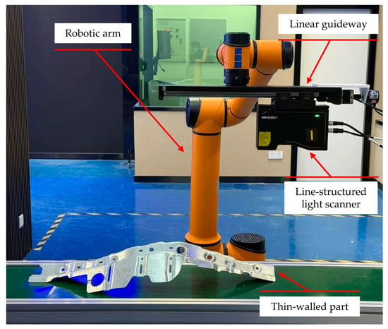
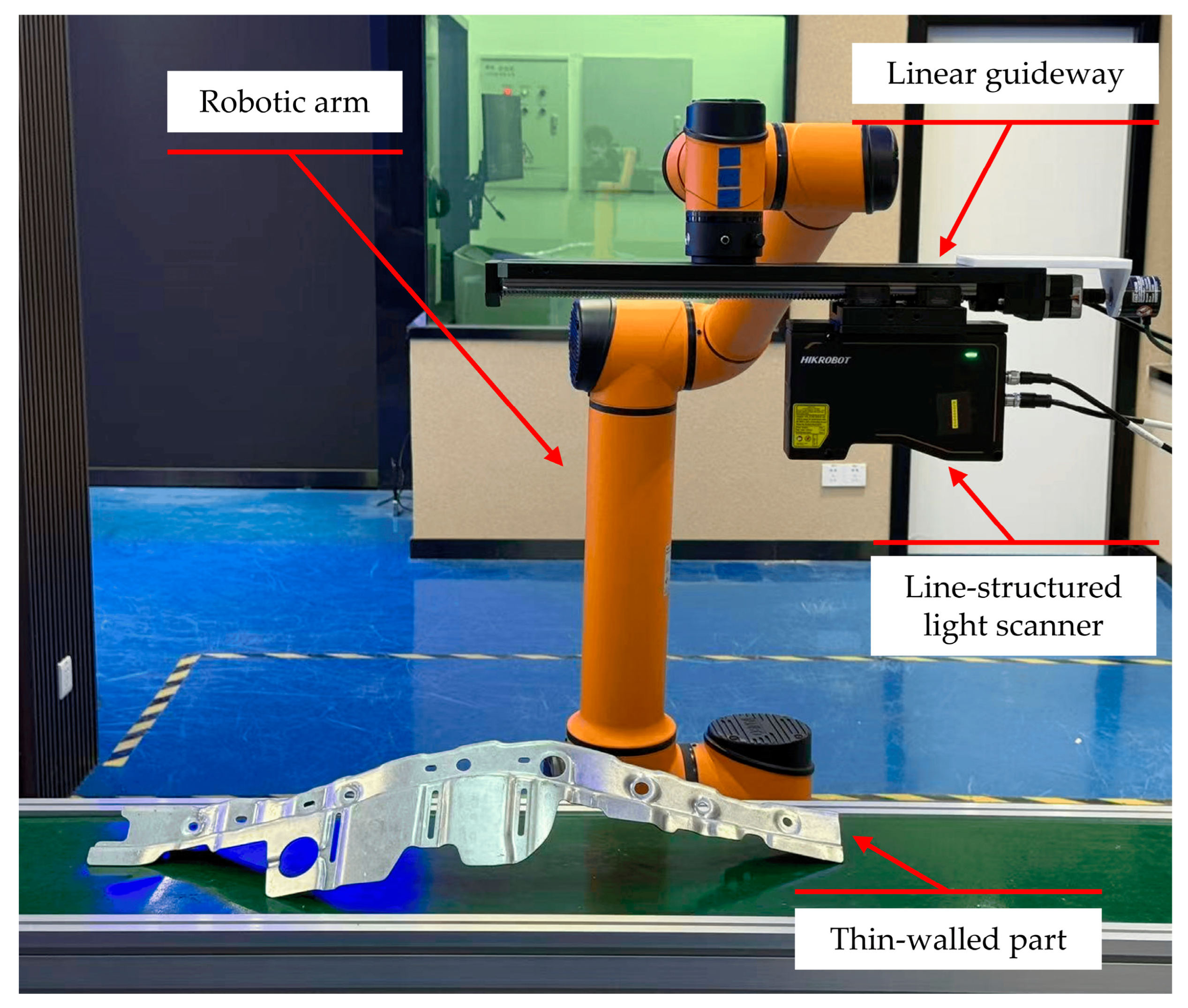
A thin-walled part machining error measurement system based on line-structured light is established in this research, as shown in Figure 1. The system consists of a six-axis robotic arm, a precision linear guide, and a line-structured light sensor. During the measurement process, the six-axis robotic arm positions the line-structured light sensor and the precision linear guide at designated locations, after which the precision linear guide drives the line-structured light sensor to perform surface scanning.
Figure 1.
A thin-walled part machining error measurement system based on line-structured light scanner.
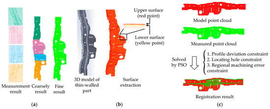
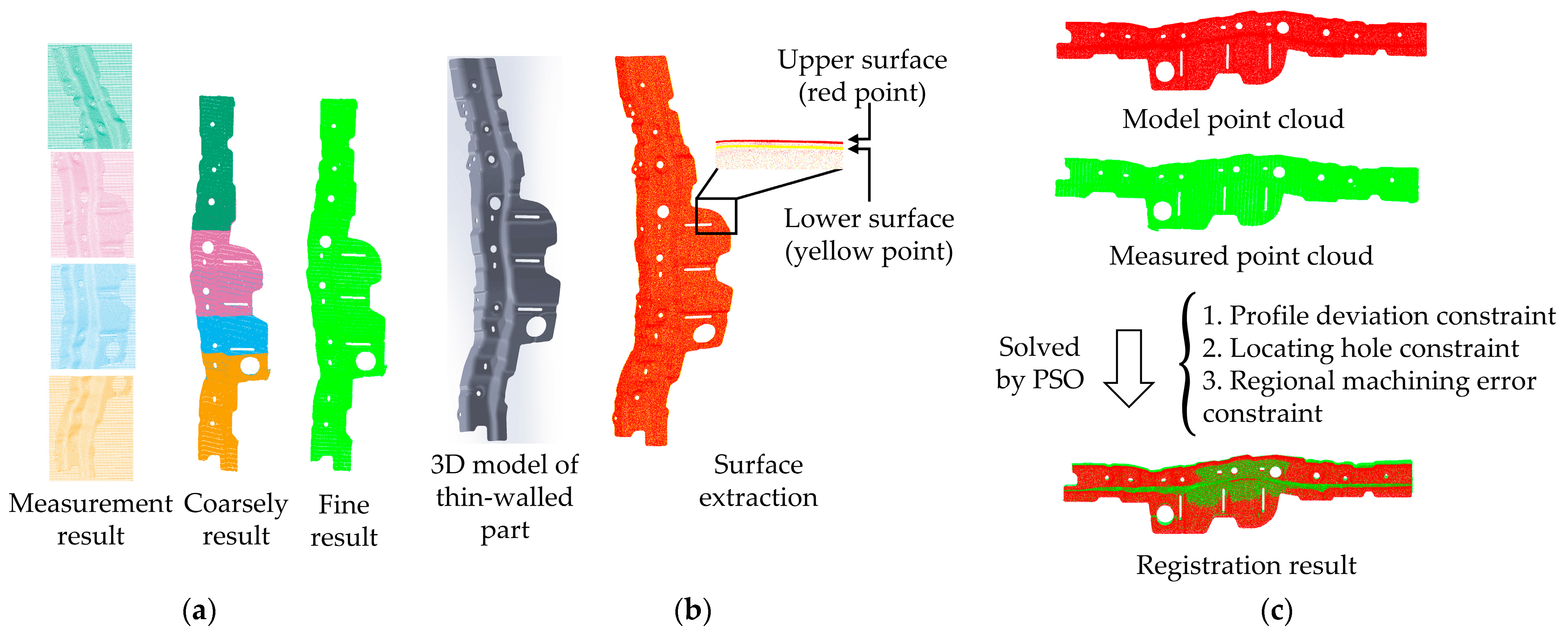
To address the machining error measurement of thin-walled parts in automotive production line scenarios, this research proposes a multi-constraint point cloud registration method for machining error measurement of thin-walled parts, as illustrated in Figure 2. To acquire the complete measured point cloud, a point cloud stitching method based on hole boundary features is employed to stitch multiple segments of thin-walled part point clouds, as shown in Figure 2a. The multi-segment point clouds are coarsely aligned through hole boundary feature matching, followed by fine registration using the Iterative Closest Point (ICP) algorithm to improve stitching accuracy. To generate a model point cloud corresponding to the measured data, a point cloud surface extraction method based on normal neighborhood search is applied to extract the target surface from the standard thin-walled part model, as shown in Figure 2b. By unifying point normals and performing neighborhood searching along the normal directions, the upper and lower surfaces of the model point cloud are effectively separated. Considering the locating and assembly relationships between thin-walled parts and fixtures, a multi-constraint objective function integrating profile deviation constraint, locating hole constraint, and regional machining error constraint is constructed, as shown in Figure 2c, and is solved using a PSO algorithm.
Figure 2.
A multi-constraint point cloud registration method for machining error measurement of thin-walled parts: (a) Point cloud stitching method based on hole boundary features; (b) Point cloud surface extraction method based on normal neighborhood search; (c) Multi-constraint point cloud registration.
3.1. Point Cloud Stitching Method Based on Hole Boundary Features
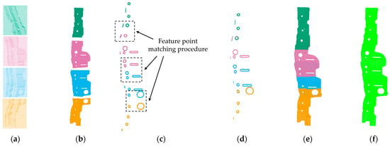
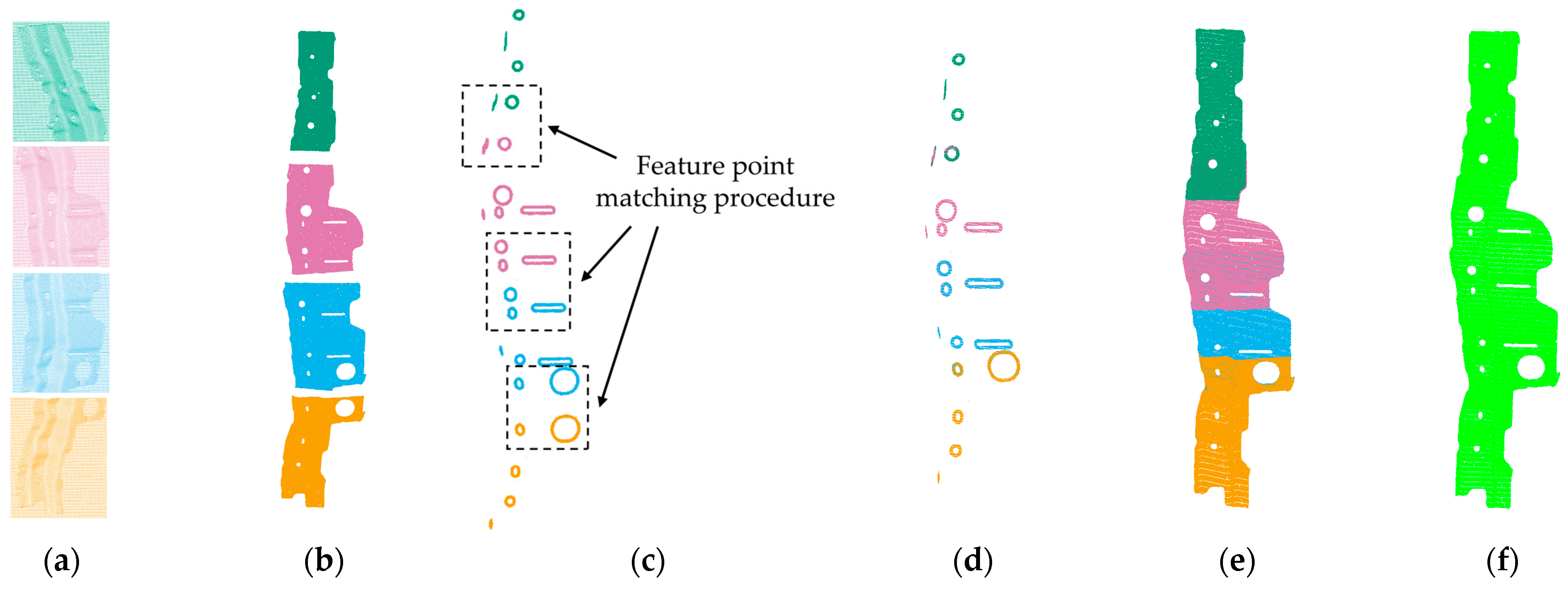
Due to the large dimensions and complex geometries of thin-walled parts, a single scan is often insufficient to cover the entire surface. Consequently, multiple scans from different viewpoints are required, and the acquired point clouds must be stitched to form a complete measured dataset. For complex thin-walled parts with high aspect ratios and significant curvature variations, large viewpoint differences result in low overlap between point clouds and indistinct geometric features, making it difficult to establish stable feature correspondences and leading to unreliable initial registration. In order to address the point cloud stitching problem of thin-walled parts under the low overlap conditions and complex structures, this research proposes a measurement point cloud stitching method based on hole boundary features, as illustrated in Figure 3.
Figure 3.
Point cloud stitching method based on hole boundary features. (a) Measurement result; (b) Denoised measured point cloud; (c) Extracted feature point cloud; (d) Feature point matching results, in which matched point cloud pairs are determined by combining the number of feature correspondences and normal consistency; (e) Coarse result; (f) Fine result.
The proposed method consists of two stages: coarse stitching and fine stitching. In the coarse stitching stage, point cloud data of the thin-walled part are first acquired using the measurement system, as shown in Figure 3a. The multiple sets of point cloud data obtained from the system are then denoised, and noise introduced during the measurement process is removed using a statistical filtering algorithm, as illustrated in Figure 3b.
After point cloud pre-processing, the local normal distribution of each point cloud is first computed. Subsequently, hole boundary feature points are extracted using a method based on local normal distribution analysis and boundary clustering, as shown in Figure 3c. Specifically, the normal vector of each point in the point cloud is estimated by local neighborhood plane fitting. After obtaining the normal vectors, whether a point belongs to a boundary is determined according to the angular distribution of its neighboring points within the plane perpendicular to the normal direction. For an arbitrary point in the point cloud, the direction vector to each neighboring point is defined as:
Project the direction vector onto the normal plane perpendicular to point to obtain the projected vector :
Calculate the polar angle of the projection vector:
After obtaining the polar angles, calculate the adjacent polar angle difference and determine the maximum polar angle difference :
The maximum polar angle difference is used to identify hole boundary points: if exceeds the threshold , the point is classified as a hole boundary point. The threshold defines the maximum allowable angular gap in the projected local neighborhood, reflecting the expected continuity of surface sampling in non-boundary regions. Based on empirical observations of the sensor’s typical sampling density, is set to 90°, which reliably distinguishes hole boundary points from interior surface points.
After extracting the hole boundary points of each point cloud, candidate point cloud pairs for coarse registration are selected based on the proportion of boundary point counts and normal consistency, as illustrated in Figure 3d. Let and denote the sets of hole boundary points of two point clouds, respectively. Their quantity ratio is defined as:
where is defined as the ratio of the numbers of hole boundary points between the two point clouds. When , the two point clouds are considered comparable in terms of hole boundary feature quantity, where and are the minimum and maximum allowable ratios, respectively. The ratio thresholds and are defined to accommodate variations in the number of detected hole boundary points caused by viewpoint changes and partial occlusions. Based on empirical observations of the sensor’s sampling characteristics, and are set to [0.8, 1.25], ensuring comparability of hole boundary feature quantities while minimizing the risk of mismatched point cloud pairs.
In addition, to quantify the consistency of normal distributions between the two sets of boundary points, the normal consistency error is defined as:
where and are points in the two-hole boundary point sets and , respectively, and is the unit normal vector of a point. When the normal consistency error is smaller than the maximum allowable normal deviation , the two point clouds are considered consistent in terms of hole boundary normal distribution and can be selected as candidate point cloud pairs for subsequent coarse stitching. The normal consistency threshold is set to accommodate expected measurement noise and local normal estimation errors. Its value is empirically chosen based on the sensor’s sampling density and surface roughness, providing a balance between robustness against noise and the ability to discriminate inconsistent point clouds.
For each selected point cloud pair, the initial rotation and translation matrices are obtained through global matching of geometric features, and the estimated transformation is applied to the corresponding point clouds to achieve preliminary stitching of the multi-segment data, as shown in Figure 3e. After determining the candidate point cloud pairs to be stitched, point correspondences are established based on their hole boundary feature points, and the initial rotation matrix and translation vector are solved. Let the matched point pairs be denoted as ; the coarse registration can then be formulated as a classical rigid transformation least-squares problem:
In the fine stitching stage, the ICP algorithm is employed to iteratively refine the registration results by minimizing the point-to-point distance error within local neighborhoods, thereby achieving high-precision fine registration between point clouds. As a result, a complete measured point cloud for subsequent registration is obtained, as shown in Figure 3f.
It should be noted that the proposed coarse stitching strategy assumes the presence of reliable locating hole boundary features, which are commonly available in automotive thin-walled parts due to assembly and positioning requirements. This assumption enables robust registration under low-overlap conditions but may limit the direct applicability of the method to parts lacking such geometric features.
3.2. Point Cloud Surface Extraction Method Based on Normal Neighborhood Search
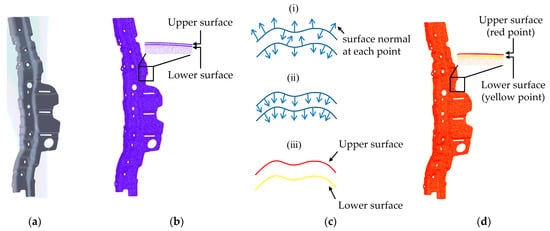
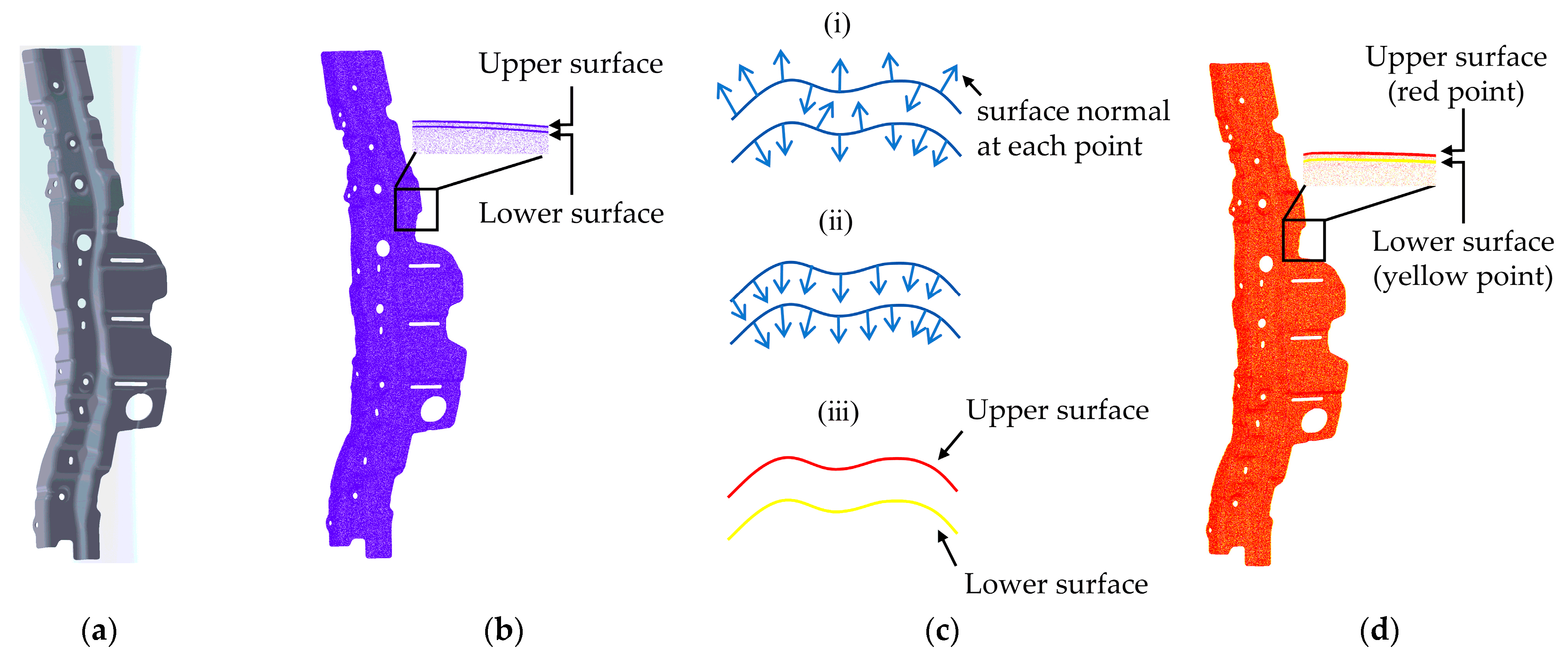
The primary geometric features of thin-walled parts are mainly distributed over large-area surfaces, and complete dimensional information can be obtained by scanning only these surfaces during measurement. Since the acquired measured point clouds exhibit a single-layer structure, it is necessary to extract the corresponding single-layer surface point cloud from the point cloud converted from the three-dimensional model of the thin-walled part for registration. To this end, this research proposes a point cloud surface extraction method based on normal neighborhood searching, which effectively avoids the influence of normal flipping on surface extraction and thereby improves the accuracy and robustness of surface extraction for complex thin-walled structures, as illustrated in Figure 4.
Figure 4.
Point Cloud Surface Extraction Method Based on Normal Neighborhood Search: (a) 3D model of thin-walled part; (b) Model point cloud converted from the 3D model; (c) Surface extraction procedure; (i) Normal vector estimation for each point; (ii) Normal vector unification; (iii) Neighborhood searching along the normal direction; (d) Extracted model point cloud.
First, the 3D model of the thin-walled part is obtained, as shown in Figure 4a. The 3D model is then converted into point cloud data. Since 3D modeling software typically employs solid modeling, the resulting model point cloud contains both upper and lower surface layers, forming a double-layer point cloud structure, as illustrated in Figure 4b.
To satisfy the requirements of subsequent point cloud registration, a surface extraction method based on normal neighborhood searching is employed to extract the corresponding single-layer surface point cloud from the double-layer point cloud, as shown in Figure 4c. First, a conventional local neighborhood plane fitting approach is used to estimate the normal vectors of points in the model point cloud. Specifically, for each point, a least-squares plane is fitted to its neighboring point set, and the normal vector of the fitted plane is taken as the initial normal estimate, as illustrated in Figure 4(ci). In this research, the initial normal vector of each point is estimated by fitting a plane to its neighboring points .
Due to the characteristics of thin-walled structures, such as small thickness and complex curvature variations, normal flipping may occur in certain regions during local surface fitting. To eliminate the interference caused by normal inversion, a global normal orientation unification is performed on the computed point cloud. By analyzing the overall geometric configuration of the thin-walled part, a global reference direction is defined, and the normals of points on the upper and lower surfaces are consistently adjusted to a unified orientation. This process ensures the spatial consistency of normal vectors across the entire point cloud, as illustrated in Figure 4(cii). In this research, the direction of the external coordinate system of the measurement setup is selected as the global reference direction for normal unification.
After normal unification, a normal-guided neighborhood search is performed along the normal direction of each point to determine its layer affiliation within the thin-walled structure. If neighboring points are detected along the normal direction of a given point, the point is classified as belonging to the upper surface; otherwise, it is identified as part of the lower surface, as illustrated in Figure 4(ciii). In this research, a k-d tree-based spatial neighborhood search method is employed, and a normal direction constraint is incorporated to guide the search. The normal search distance is defined as , and the normal-guided neighborhood set is constructed accordingly:
Based on the results of the neighborhood search, the layer affiliation of each point within the thin-walled structure is determined. If , it indicates that neighboring points exist along the normal direction of the point, and the point is classified as belonging to the upper surface. Conversely, if , it implies that no neighboring points are detected along the normal direction, and the point is identified as part of the lower surface. As a result, the model point cloud corresponding to the measured point cloud is finally obtained, as shown in Figure 4d.
3.3. Multi-Constraint Point Cloud Registration
To accurately evaluate the machining errors of thin-walled parts, it is necessary to register the stitched measured point cloud with the corresponding model point cloud. Conventional point cloud registration methods usually minimize only point-to-point or point-to-surface distance metrics. However, thin-walled parts often exhibit global deformation during forming and assembly processes, experience shifts in locating datums, and present different accuracy requirements across functional regions. Under these conditions, registration based solely on global shape consistency is insufficient to reliably characterize the actual machining errors. Therefore, this research proposes a novel machining error measurement method for thin-walled parts based on multi-constraint point cloud registration. A registration model that integrates profile deviation constraint, locating hole constraint, and regional machining error constraint is constructed to obtain an optimal registration result that satisfies assembly relationships and geometric tolerance requirements.
Profile deviation constraint: Due to the influence of manufacturing processes such as stamping, deformation may exist between thin-walled parts and the nominal model. To minimize dimensional deviations caused by shape inconsistency, the classical ICP method is directly adopted as the evaluation criterion, and an objective optimization function is constructed based on the distances between corresponding nearest points. For any point on the measured point cloud, find a point on the model point cloud such that the Euclidean distance between the registered and is minimized:
where , , with and denoting the rotation matrix and translation vector to be estimated, respectively.
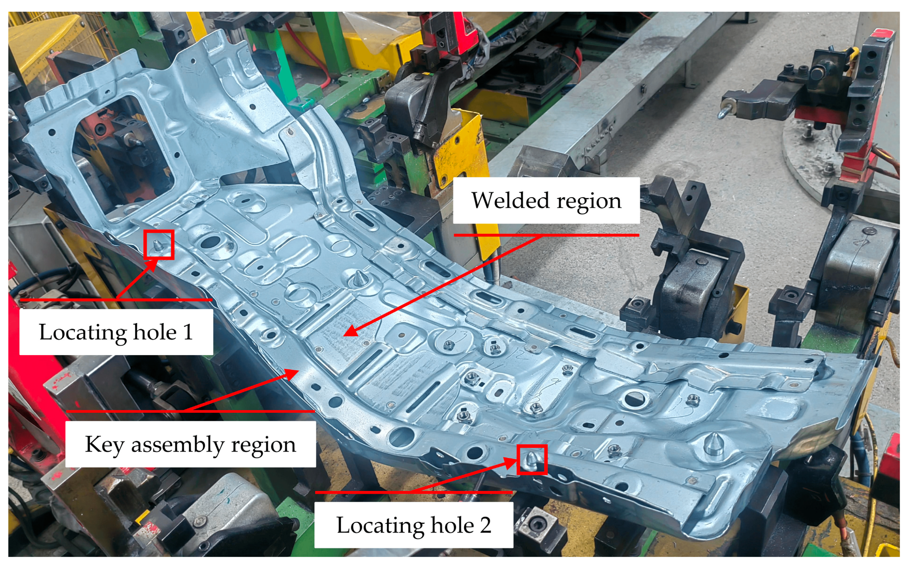
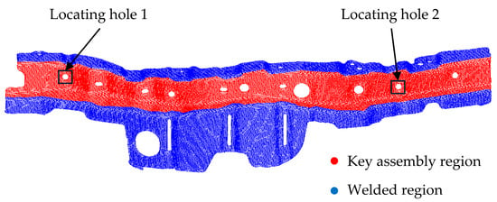
Locating hole constraint: Thin-walled parts are generally constrained by locating holes during the assembly process; therefore, accurate alignment of the locating holes constitutes a fundamental requirement when assembly constraints are taken into account. As shown in Figure 5, the locating holes are located at both ends of the thin-walled part. Using the locating hole feature extraction method described in Section 3.1, the centroid coordinates of the surface locating holes are extracted from the measured point cloud and denoted as , while the corresponding centroid coordinates are extracted from the model point cloud and denoted as . is the number of locating holes. The locating-hole constraint equation can thus be defined as:
Figure 5.
Assembly site for thin-walled parts.
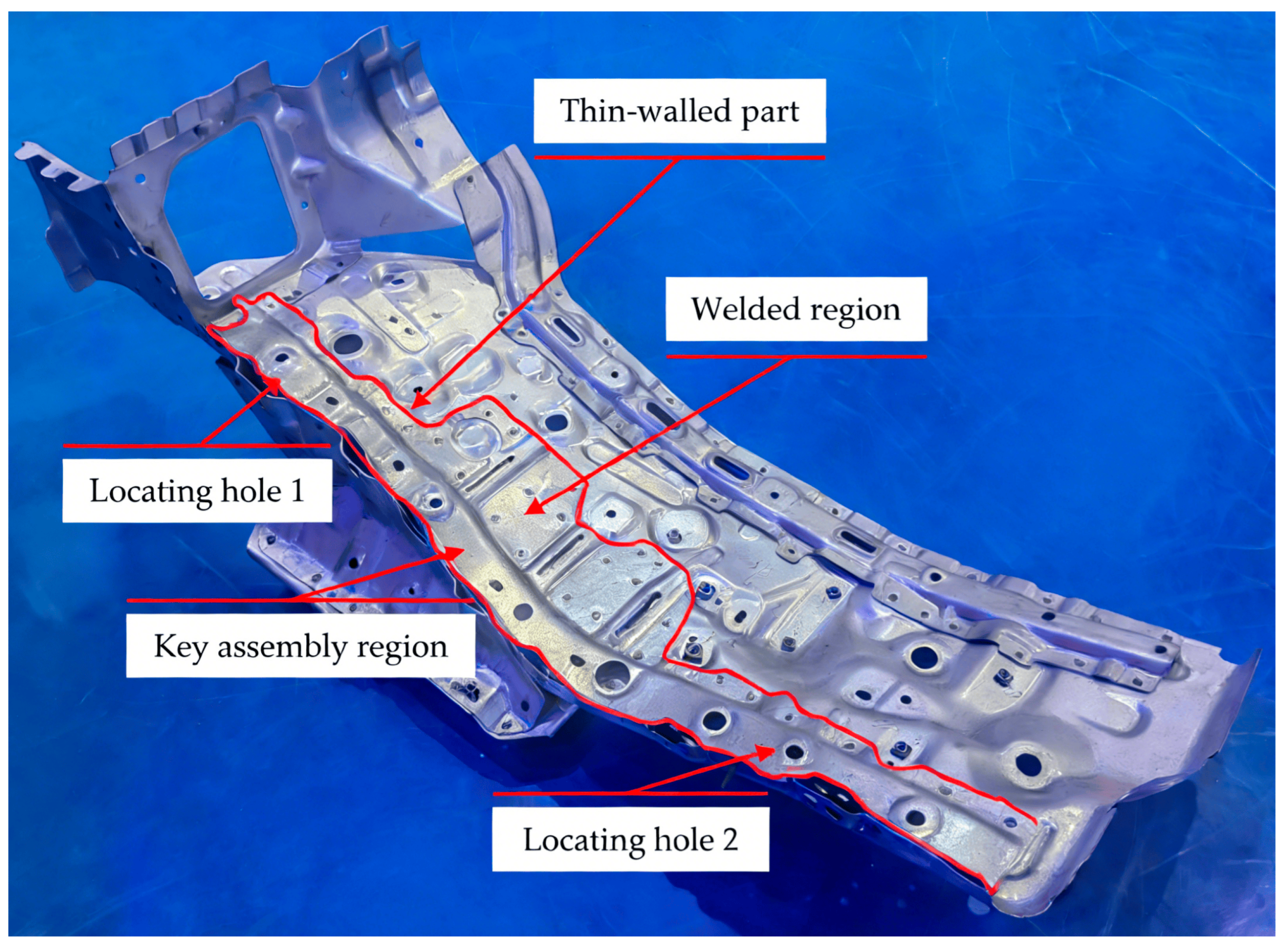
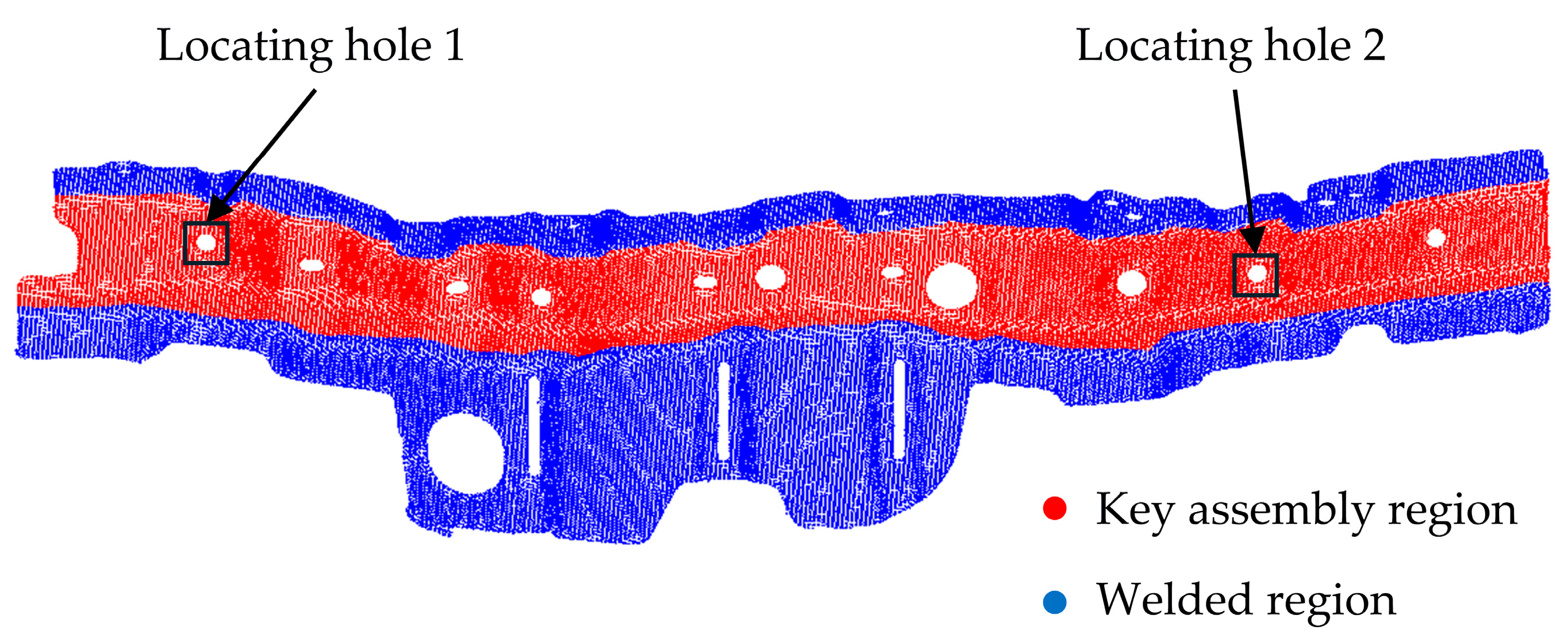
Regional machining error constraint: During the welding and assembly process, thin-walled parts can be categorized into welded region and key assembly region according to whether they participate directly in assembly. Different regions impose different requirements on assembly accuracy, and the machining error in each region should be maintained below the allowable maximum machining error during assembly. In this research, the point cloud of the thin-walled part is divided into a welded region point cloud and a key assembly region point cloud, as illustrated in Figure 6.
Figure 6.
The assembled component.
The division of the thin-walled part into the welded region and the key assembly region is guided by the assembly semantics provided in the CAD model rather than purely data-driven clustering. Specifically, the key assembly region is defined as the set of functional features that directly participate in assembly positioning and tolerance control, such as locating holes, mating surfaces, and their adjacent neighborhoods. The remaining areas, which mainly undergo welding-induced deformation and do not directly determine assembly accuracy, are classified as the welded region. In the current implementation, the region labeling is performed in a semi-manual manner based on CAD assembly annotations and engineering knowledge, and the corresponding labels are transferred to the measured point cloud via nearest-neighbor mapping. The final region division is shown in Figure 7.
Figure 7.
Regional division of thin-walled part.
This process is only required once for a given part and does not affect the subsequent registration optimization. Therefore, the proposed regional constraint formulation is not restricted to the investigated component. For other thin-walled parts with welded structures, the same principle can be applied by identifying assembly-critical features from CAD models or assembly specifications and treating them as key regions with stricter error constraints.
The constraint equations for each region can be defined as:
where is the number of points in the corresponding region; is the coordinate of the i-th point in the measured point cloud; is the coordinate of the i-th point in the model point cloud; is the normal vector at point ; and are the machining errors of the i-th point in the key assembly region and the welded region, respectively; and are the allowable maximum machining errors for the key assembly region and the welded region, respectively.
By integrating the three constraints involved in the multi-constraint registration process, the objective function is defined as:
The objective function constitutes a nonlinear constrained optimization problem, which would incur high computational complexity if solved directly. To improve the practical implementability and computational efficiency of the algorithm, the constraints are transformed into penalty functions. In this research, a sigmoid-type penalty function is adopted. Compared with conventional linear and ReLU-based penalty functions, the sigmoid function allows the penalty intensity to be flexibly controlled by adjusting the steepness parameter . This property enables intelligent optimization algorithms to perform a more efficient global search on a continuous and smooth cost surface, thereby significantly improving the convergence stability and accuracy of the registration optimization. The objective function with the incorporated penalty term is formulated as:
where and are the weighting coefficients for the key assembly region and the welded region, respectively, with ; and are the numbers of points in the key assembly region and the welded region, respectively; and is the penalty function, which transforms the regional machining error constraints and into penalty terms in the objective function. When or does not satisfy the constraint requirements, the penalty function returns a large value, thereby guiding the optimization search back to the feasible region.
To obtain the optimal transformation matrix that satisfies the multiple geometric constraints across different regions, the constrained registration objective function is solved using the particle swarm optimization (PSO) algorithm. PSO is a global optimization method based on swarm intelligence, which searches for the optimal solution by simulating the cooperation and information sharing among individuals in a swarm. Owing to its inherent parallelism and ease of implementation, PSO offers fast convergence and is well-suited for solving nonlinear, high-dimensional, and complex optimization problems.
The computational cost of the PSO-based registration method is mainly determined by the number of particles and the number of iterations . For a typical point cloud with approximately 10,000 points, the registration process with and completes within 20 min on a standard desktop CPU. While PSO generally requires higher computational resources than gradient-based methods, it is robust to local minima and does not require analytical gradients, making it particularly suitable for complex multi-constraint registration tasks. Moreover, the algorithm is highly parallelizable since the fitness evaluation of each particle is independent, which can further accelerate computation on multi-core or GPU platforms.
First, based on the properties of rotation-translation matrices, create a six-dimensional search particle X comprising translation vectors along the , and axes and rotation vectors . The six-dimensional search particle X and its search range are as follows:
where , , , , and are the search bounds for , , , , and , respectively.
After establishing the six-dimensional search particles, the fitness vector for each particle X is:
To reflect the varying importance of different constraints, normalization and weighting are introduced. The particle fitness expression is defined as follows:
Based on practical measurement experience, among the three constraint conditions, the locating hole constraint is the most key, followed by the regional machining error constraint, while the profile deviation constraint is the least key. Accordingly, the weighting coefficients satisfy , with .
After establishing the particle fitness expression, create the PSO model with the particle count set to . The particle update formula after each iteration is:
where and are the velocities of the i-th particle at iterations and , respectively. and are the positions of the i-th particle at iterations and , respectively. refers to the historical optimal position of the i-th particle, and refers to the global optimal position. denotes the inertia weight. and denote the learning factors that control particle self-learning and swarm learning, respectively. and denote random numbers in the interval 0~1.
To ensure that particle swarm optimization balances global exploration and local convergence during the search process while obtaining the global optimum solution, this research employs an adaptive parameter adjustment strategy based on the sine function:
where is the current iteration index of the particle at the -th iteration, and is the maximum number of iterations. The inertia weight bounds , and . The cognitive learning factor is gradually decreased with iterations, whereas the social learning factor is gradually increased; and the inertia weight is decreased as the iteration proceeds. This adaptive regulation mechanism enables particles to maintain strong exploration capability in the early stage and enhanced convergence capability in the later stage, thereby improving the global optimization performance.
As the number of iterations increases, population diversity decreases. To avoid getting stuck in local optima, we establish the population diversity expression :
where denotes the mean position of all particles. When the population diversity falls below the specified threshold , perturbation particles are generated and added to the population.
After the iteration is complete, convert the final optimized parameters into the transformation matrix :
where , and are the rotation matrices about the , , and axes, respectively, and , and are the translation matrices along the , and axes, respectively.
4. Experiments and Analysis
In this section, the effectiveness of the proposed multi-constraint registration method is validated. The experimental data processing platform is based on an Intel (R) Core (TM) i7-14700HX processor with the Windows 11-x64 operating system. The algorithm is implemented in C++ using Visual Studio 2022 and compiled with the third-party PCL version 1.14.1.
4.1. Data Collection and Preliminary Processing
First, a thin-walled part machining error measurement system based on line-structured light scanner is employed to acquire point cloud data. The six-axis robotic arm used in the system is an AUBO-i10, and its detailed specifications are listed in Table 1. The line-structured light scanner is an MV-DP3300, with detailed parameters provided in Table 2. The specifications of the linear guideway are summarized in Table 3. During the measurement process, a computer controls the six-axis robotic arm to position the line-structured light scanner and the linear guideway at predefined locations; subsequently, the linear guideway, also controlled by the computer, drives the scanner to perform scanning, and the point cloud data transmitted by the scanner are then acquired.
Table 1.
Specifications of six-axis robotic arm.
Table 2.
Specifications of line-structured light scanner.
Table 3.
Specifications of linear guideway.
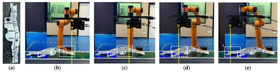
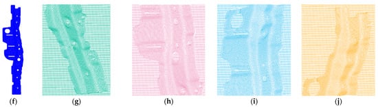
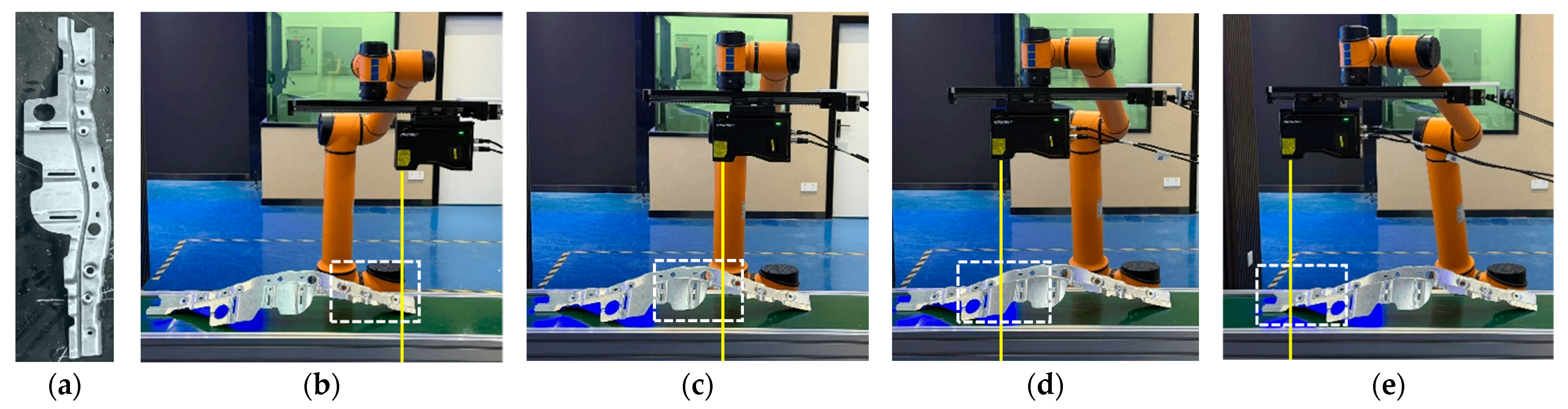
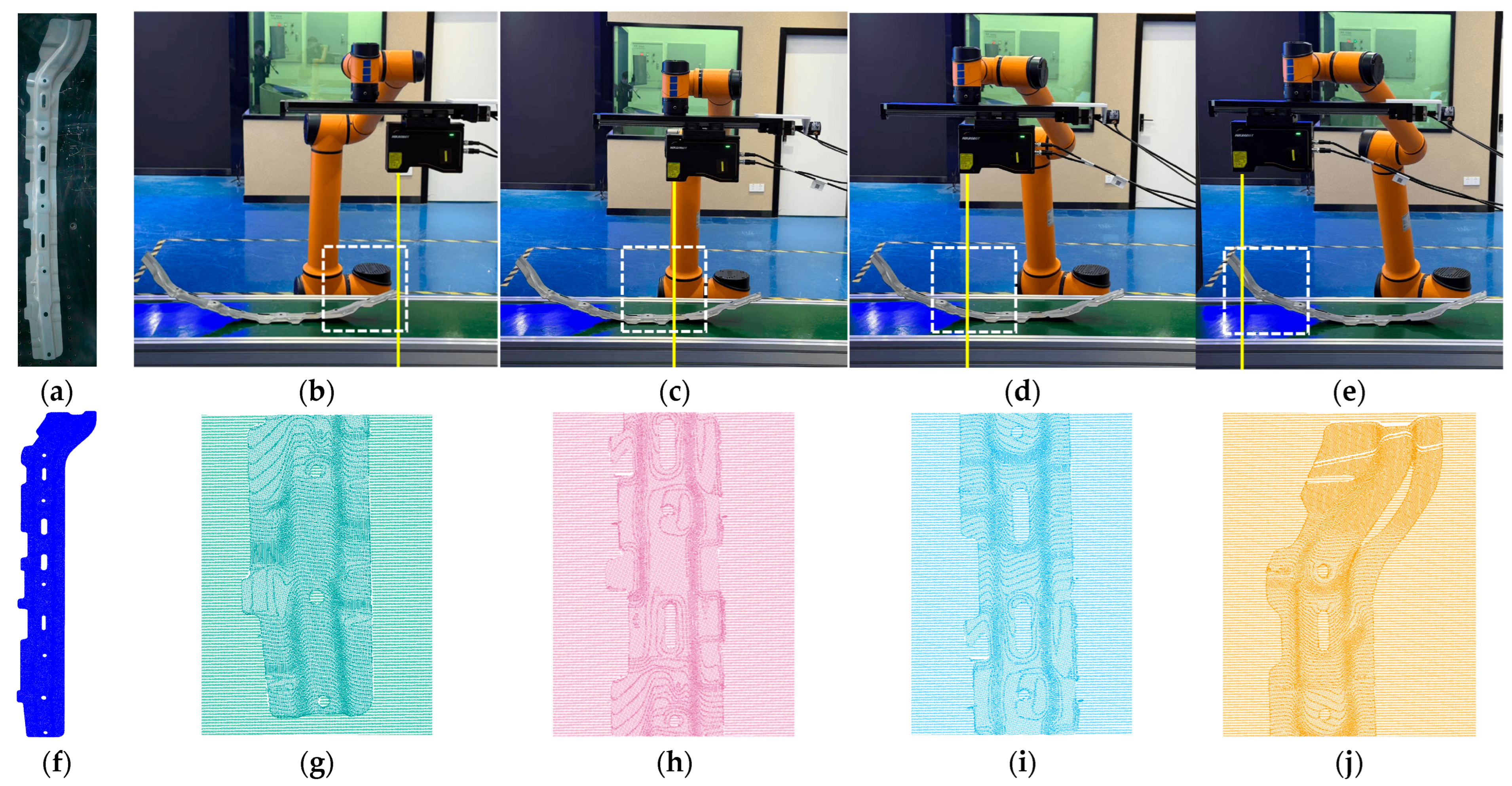
The experimental data used in this research were obtained from physical samples of typical thin-walled structural components provided by an automotive parts manufacturing enterprise. To ensure the repeatability and reliability of the experimental data, each thin-walled component was independently scanned multiple times, as illustrated in Figure 8, Figure 9 and Figure 10. The processed sets of measurement point clouds were subsequently used as input data for point cloud surface extraction, point cloud stitching, and registration experiments.
Figure 8.
Measurement Process of Thin-Walled Part 1: (a) Physical specimen of thin-walled part 1; (b–e) Measurement process, the yellow indicator line represents the laser line position, and the white dashed border indicates the scanning range for each scan; (f) Model point cloud of thin-walled part 1; (g–j) Point clouds acquired during the measurement process.
Figure 9.
Measurement Process of Thin-Walled Part 2: (a) Physical specimen of thin-walled part 2; (b–e) Measurement process, the yellow indicator line represents the laser line position, and the white dashed border indicates the scanning range for each scan; (f) Model point cloud of thin-walled part 2; (g–j) Point clouds acquired during the measurement process.
Figure 10.
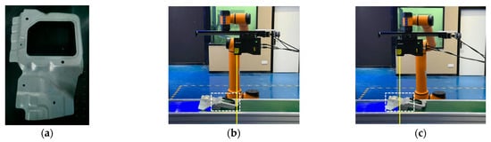
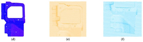
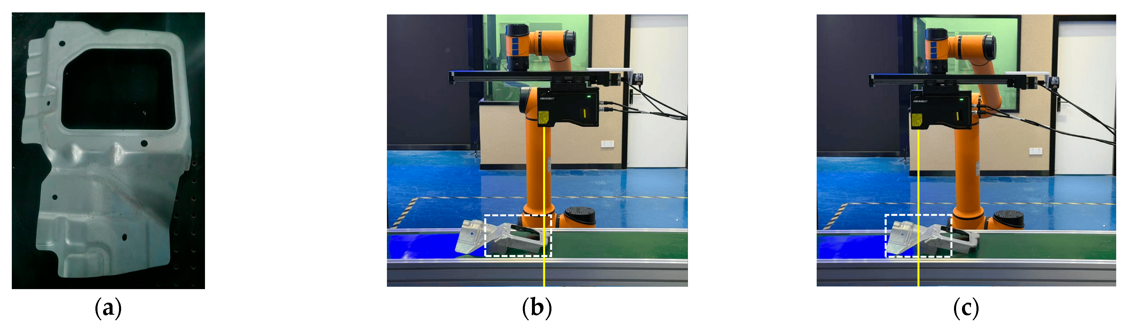
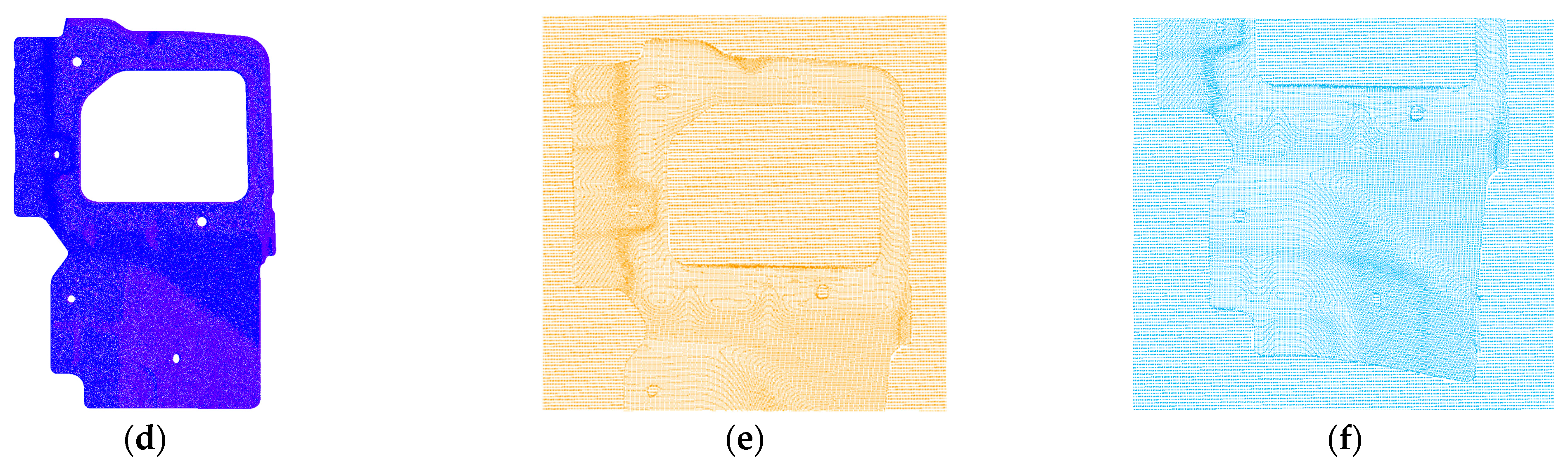
Measurement Process of Thin-Walled Part 3: (a) Physical specimen of thin-walled part 3; (b,c) Measurement process, the yellow indicator line represents the laser line position, and the white dashed border indicates the scanning range for each scan; (d) Model point cloud of thin-walled part 3; (e,f) Point clouds acquired during the measurement process.
4.2. Comparative Experiment
4.2.1. Validation of the Point Cloud Stitching Method
The point cloud stitching method proposed in Section 3.1 was applied to multiple sets of point cloud data acquired from scanning. During the point cloud preprocessing stage, a statistical outlier removal filter was employed to denoise the raw point clouds, with the number of neighboring points set to and the standard deviation threshold set to . In the normal estimation stage, K-nearest neighbor (KNN) search was used to perform local plane fitting for normal computation, with the neighborhood size set to . During the extraction of hole boundary feature points, the maximum polar angle difference threshold was set to . For the matching and screening of candidate point cloud pairs, the boundary point ratio thresholds were set to and , and the maximum allowable normal deviation threshold was set to .
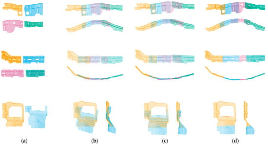
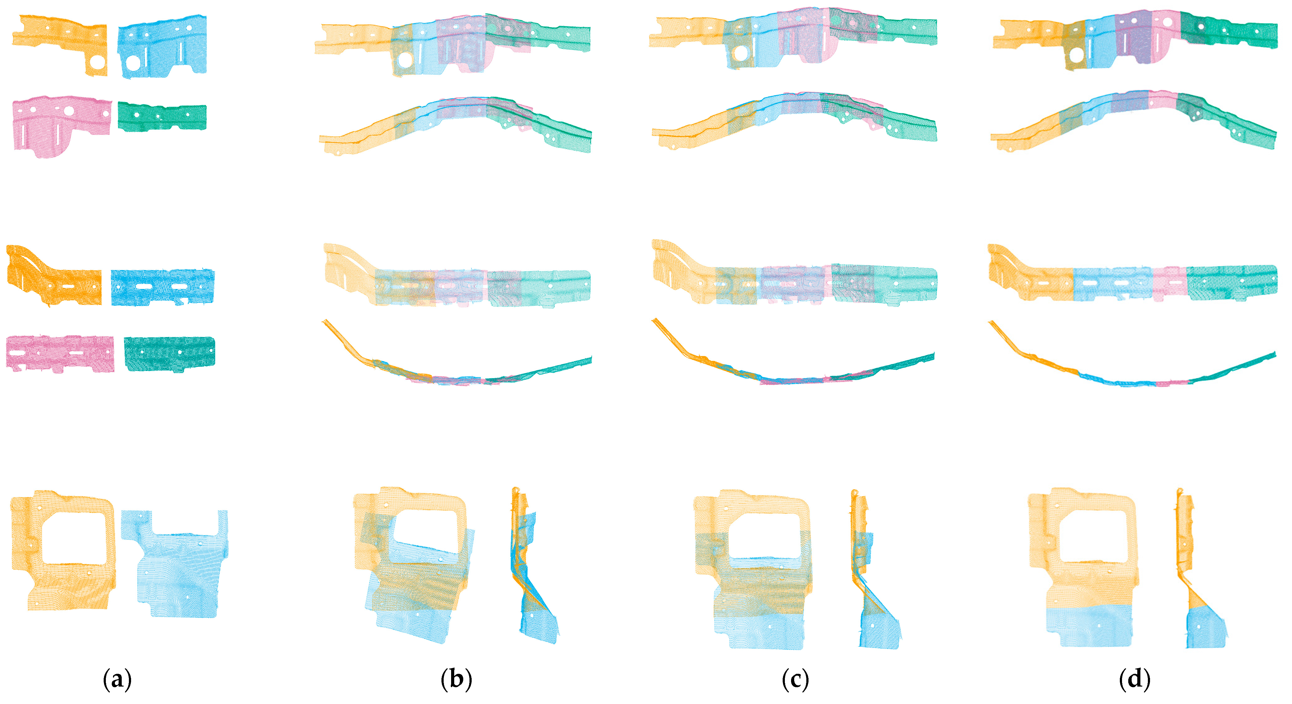
To validate the advantages of the proposed point cloud stitching method for thin-walled part point cloud stitching, this research selected two representative point cloud stitching methods, FPFH-SAC-IA-ICP and SHOT-RANSAC-ICP, as comparative methods, as shown in Figure 11.
Figure 11.
Results of thin-walled parts 1, 2, and 3 using different point cloud stitching methods: (a) Denoised partial measured point clouds; (b) FPFH-SAC-IA-ICP method; (c) SHOT-RANSAC-ICP method; (d) Proposed method.
The point cloud dimensions obtained using different stitching methods are summarized in Table 4. Compared with the FPFH-SAC-IA-ICP method and SHOT-RANSAC-ICP method, the proposed method achieves reductions of approximately 70.8%, 77.1% and 86.2% in overall dimensional error for the three thin-walled parts, respectively, resulting in improved geometric consistency and global accuracy.
Table 4.
Point cloud dimensions by different stitching methods (mm).
4.2.2. Validation of the Point Cloud Surface Extraction Method
After stitching the measured point clouds, the surface extraction method described in Section 3.2 was employed to segment the model point clouds of different thin-walled parts. The model point clouds were generated by converting the corresponding 3D models, with the total number of points set to approximately 1,000,000. For normal estimation, a K-nearest neighbor search with was adopted. To unify point normals, the negative Z-axis of the external coordinate system of the measurement system was selected as the global reference direction . Based on the actual thickness of the thin-walled parts, the normal-guided search distance was set to .
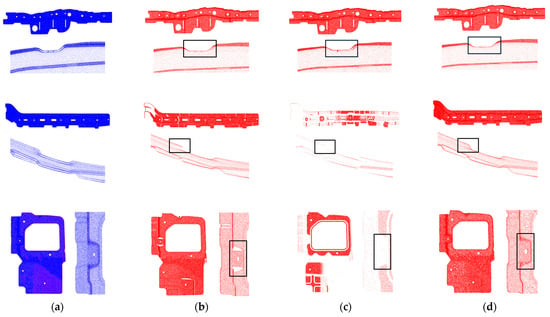
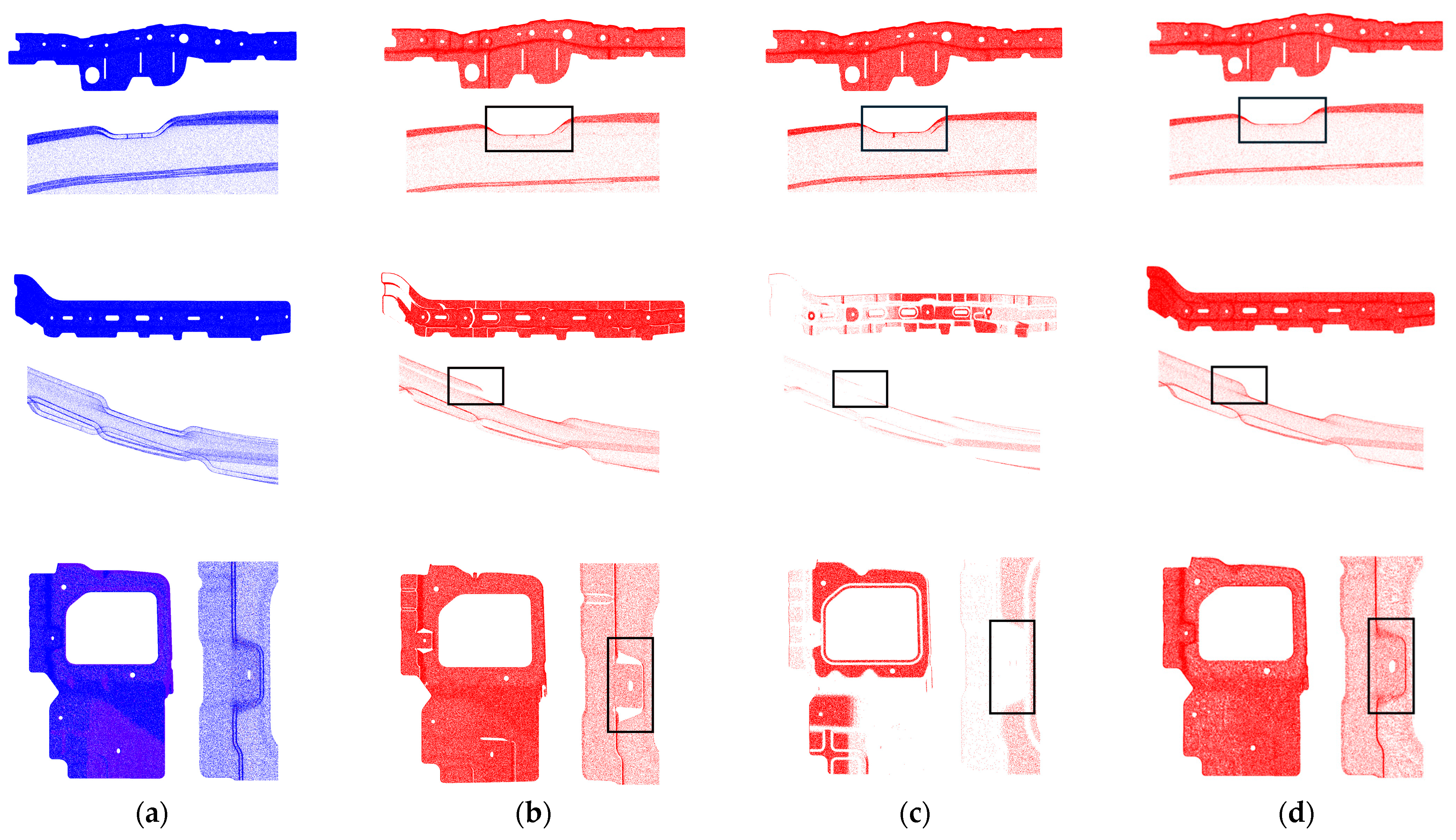
To validate the advantages of the proposed point cloud surface extraction method for thin-walled part surface extraction, this research selected two representative surface extraction methods, Normal-based Region Growing and RANSAC Plane, as comparative methods, as shown in Figure 12, where the extracted upper surface point clouds are presented.
Figure 12.
Results of thin-walled parts 1, 2 and 3 using different point cloud surface extraction methods: (a) Point cloud generated from 3D model; (b) Normal-based Region Growing method; (c) RANSAC Plane method; (d) Proposed method, the black border highlights regions with complex curvature changes, which better illustrate the extraction results.
The numbers of points in the upper and lower surface point clouds obtained by each method are listed in Table 5. As shown, compared with the Normal-based Region Growing method and RANSAC Plane method, the proposed surface extraction method maintains the difference in point counts between the upper and lower surfaces of the three sets of thin-walled part data within 200 points, achieving a reduction of over 98% compared to conventional methods and significantly improving the consistency and stability of upper and lower surface extraction for thin-walled parts.
Table 5.
Number of points on the upper and lower surfaces by different extraction methods.
4.2.3. Validation of the Multi-Constraint Registration Method
In practical implementation, the multi-constraint registration is performed with a particle swarm optimization (PSO) solver. Distance constraints for particle translation and rotation are applied to ±10 mm and ±10° to prevent physically infeasible solutions and maintain registration stability. Based on engineering requirements, the maximum allowable machining errors for key assembly region and welded region are set to and , respectively. The particle number is set to 50, which ensures sufficient swarm diversity for global search while keeping the computational cost within acceptable limits for industrial applications.The inertia weight is adaptively adjusted to encourage broad exploration in early iterations and more focused local exploitation as convergence progresses.Cognitive and social learning factors and are tuned to gradually shift the emphasis from individual particle experience to collective swarm intelligence, thereby accelerating convergence without premature stagnation.The maximum iteration count is selected based on preliminary experiments, which show that most particles approach the optimal solution well before reaching this limit.
The weights of the form deviation, locating hole, and regional machining error constraints (, , ) are chosen to reflect their relative engineering importance.A sensitivity analysis was conducted by perturbing each weight within a ±10% range while keeping the others fixed.The results indicate that such moderate variations lead to only minor changes in the final registration error and do not affect the convergence behavior or the optimal transformation, demonstrating that the proposed registration framework is not overly sensitive to precise weight tuning and exhibits robust performance with respect to parameter selection.
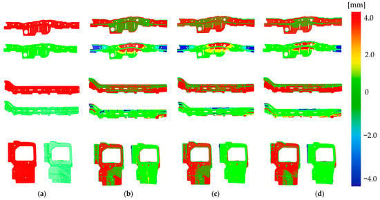
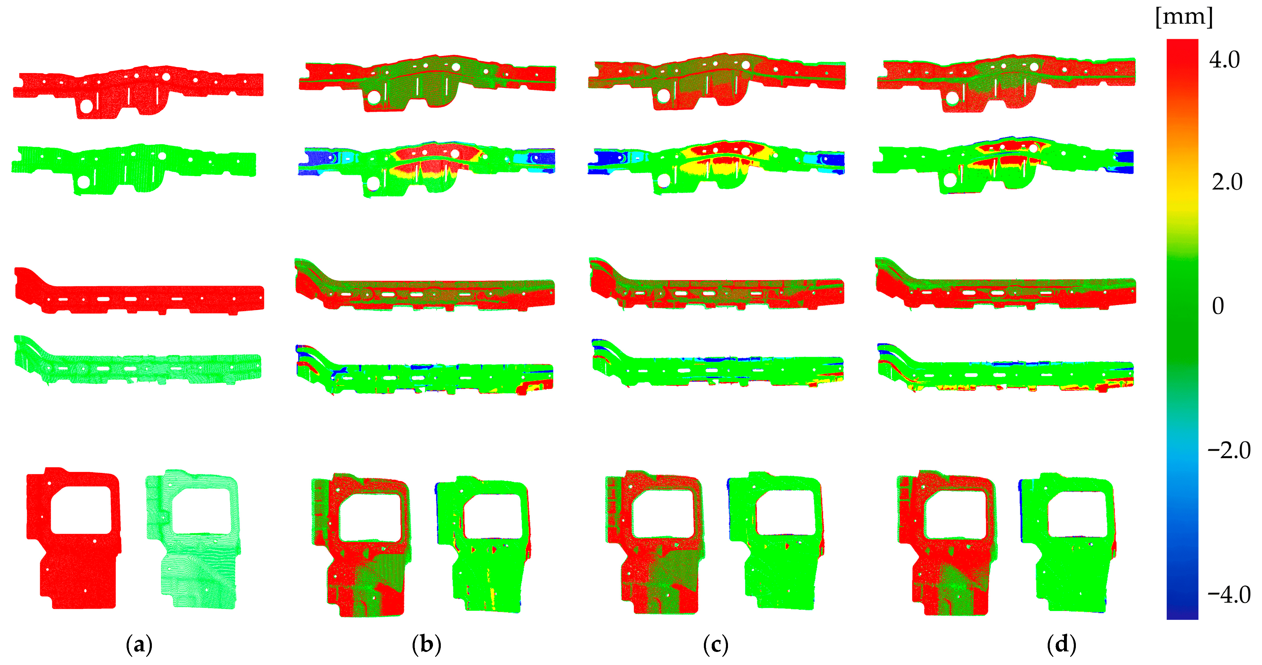
To validate the advantages of the proposed multi-constraint registration method in machining error evaluation of thin-walled parts, two comparative registration strategies were considered, as shown in Figure 13.
Figure 13.
Results of thin-walled parts 1, 2 and 3 using different point cloud registration methods: (a) Model point cloud and measured point cloud before registration; (b) SGO-PSO method; (c) GF-MCR method; (d) Proposed method.
The first method is a classical registration method without multi-constraint conditions, namely SGO-PSO (Single Global Objective PSO), in which all point pairs are treated uniformly and optimized using a single global objective function solved by particle swarm optimization (PSO), without distinguishing different functional regions or imposing region-specific error constraints. This method is introduced to explicitly evaluate the contribution of multi-constraint modeling to machining error assessment.
The second method is a commonly used multi-constraint registration method based on geometric feature constraints, referred to as GF-MCR (Geometric Feature Multi-Constraint Registration), in which stable structural primitives such as lines and planes are extracted from the point clouds, and geometric consistency conditions are imposed to guide the registration transformation. For example, line features can be used to handle scale issues and coarse alignment, while planar features provide fine adjustment of rotation and translation. This method is introduced to explicitly evaluate the advantages of the proposed multi-constraint registration method over other commonly used multi-constraint registration approaches in the machining error assessment of thin-walled parts.
In the figure, the red point clouds represent the model point clouds, and the green point clouds represent the measured point clouds. To illustrate the machining error distribution, the registration results were evaluated using a color-coded error map: red and yellow indicate regions where the positive deviation exceeds or approaches the allowable threshold, blue and cyan indicate regions where the negative deviation exceeds or approaches the threshold, and green indicates regions that satisfy the machining error requirements.
To further evaluate the effectiveness of the proposed multi-constraint registration method, the mean regional machining error obtained by different point cloud registration methods is defined as follows:
The mean machining errors of different regions obtained by various registration methods are listed in Table 6. As shown in the table, the proposed multi-constraint registration method outperforms the SGO-PSO and GF-MCR methods across all functional regions, with particularly significant improvements observed in key assembly feature regions. In the locating hole region, the measurement accuracy of the three thin-walled parts is improved to 0.016 mm, 0.045 mm, and 0.038 mm, respectively, representing improvements of 96.3% and 95.3% compared with the SGO-PSO and GF-MCR methods. This demonstrates a substantial enhancement in the alignment accuracy of locating hole features. In the key assembly regions, the measurement accuracy achieved by the proposed method is improved to within 2 mm, corresponding to improvements of approximately 23.9% and 14.5% over the SGO-PSO and GF-MCR methods, respectively. Meanwhile, in welded regions, the proposed method maintains a comparable accuracy level to conventional methods, without any noticeable degradation in measurement performance.
Table 6.
Mean processing error by different registration methods (mm).
Overall, these results demonstrate that the proposed multi-constraint registration method can significantly enhance registration accuracy in function-critical regions while preserving overall geometric consistency, indicating strong potential for practical engineering applications.
5. Conclusions
This research proposes a multi-constraint point cloud registration framework for machining error measurement of thin-walled parts, and its effectiveness is validated through comprehensive experiments. The proposed approach systematically addresses key challenges in industrial measurement scenarios, including low-overlap multi-view point cloud stitching, interference caused by double-layer surfaces in model point clouds, and region-specific positioning and assembly requirements of thin-walled parts. Experimental results show that the point cloud stitching method based on hole boundary features reduces the overall dimensional error of point cloud stitching by approximately 70–86%, while the point cloud surface extraction method based on normal neighborhood searching decreases the point number deviation between upper and lower surfaces by more than 98%. Furthermore, by adopting a registration model integrating multiple locating and assembly constraints, the measurement accuracy in locating holes and key assembly regions is improved to 0.05 mm and 2 mm, representing improvements of approximately 96.3% and 23.9% compared with registration methods without multi-constraint conditions, and approximately 95.3% and 14.5% compared with commonly used multi-constraint registration methods.
From an engineering application perspective, the proposed multi-constraint point cloud registration framework provides a feasible and reliable solution for online machining error measurement of complex thin-walled parts in industrial environments. The method enables stable and accurate error evaluation under challenging conditions, including limited point cloud overlap, complex geometric characteristics, and strict functional tolerance requirements. When integrated with a line-structured light sensor and a six-axis robotic system, the proposed approach exhibits strong adaptability to automated measurement workflows and on-site inspection scenarios. As a result, it shows considerable potential for enhancing quality control efficiency, reducing reliance on manual inspection, and supporting intelligent manufacturing and digital quality assurance in the automotive and other precision manufacturing industries.
In addition to the validated automotive application scenario, the proposed approach shows potential applicability to other thin-walled structures and industrial domains, such as aerospace components. Since the point cloud stitching method based on hole boundary features, the point cloud surface extraction method based on normal neighborhood searching, and the registration model integrating multiple locating and assembly constraints are not inherently limited to a specific part geometry or manufacturing process, the proposed approach can be extended to thin-walled parts with different geometric features and assembly requirements through appropriate parameter adjustment. Future work will focus on further investigating such extensions and validating the proposed method in broader industrial application scenarios.
Author Contributions
Conceptualization, F.H., C.S. and D.F.; methodology, F.H., C.S. and D.F.; software, F.H., C.S. and D.F.; validation, F.H., C.S. and D.F.; formal analysis, F.H., C.S. and D.F.; investigation, C.S. and D.F.; resources, F.H., C.S. and D.F.; data curation, C.S. and D.F.; writing—original draft preparation, C.S.; writing—review and editing, F.H., C.S. and D.F.; visualization, C.S. and D.F.; supervision, F.H. and J.X.; project administration, F.H., C.S., D.F. and J.X.; funding acquisition, F.H. and J.X. All authors have read and agreed to the published version of the manuscript.
Funding
This research received no external funding.
Institutional Review Board Statement
Not applicable.
Informed Consent Statement
Not applicable.
Data Availability Statement
The original contributions presented in the research are included in the article, further inquiries can be directed to the corresponding author.
Conflicts of Interest
The authors declare no conflicts of interest.
References
- Wang, H.; Zhou, M.-X.; Zheng, W.-Z.; Shi, Z.-B.; Li, H.-W. 3D Machining Allowance Analysis Method for the Large Thin-Walled Aerospace Component. Int. J. Precis. Eng. Manuf. 2017, 18, 399–406. [Google Scholar] [CrossRef] [Scilit]
- Chen, H.; Ji, K.; Zhang, W.; Zhang, C.; Fu, J.; Zhao, P. High Precision Ultrasonic Measurement Method for Thin-Walled Parts. NDT E Int. 2024, 145, 103122. [Google Scholar] [CrossRef] [Scilit]
- Wang, Y.; Liu, Y.; Chen, H.; Xie, Q.; Zhang, K.; Wang, J. Combined Measurement Based Wing-Fuselage Assembly Coordination via Multiconstraint Optimization. IEEE Trans. Instrum. Meas. 2022, 71, 7005316. [Google Scholar] [CrossRef] [Scilit]
- Del Sol, I.; Rivero, A.; de Lacalle, L.N.L.; Gamez, A.J. Thin-Wall Machining of Light Alloys: A Review of Models and Industrial Approaches. Materials 2019, 12, 2012. [Google Scholar] [CrossRef] [Scilit] [PubMed]
- Li, X.; Li, W.; Jiang, H.; Zhao, H. Automatic Evaluation of Machining Allowance of Precision Castings Based on Plane Features from 3D Point Cloud. Comput. Ind. 2013, 64, 1129–1137. [Google Scholar] [CrossRef] [Scilit]
- Dong, Y.; Xu, B.; Liao, T.; Yin, C.; Tan, Z. Application of Local-Feature-Based 3-D Point Cloud Stitching Method of Low-Overlap Point Cloud to Aero-Engine Blade Measurement. IEEE Trans. Instrum. Meas. 2023, 72, 1008913. [Google Scholar] [CrossRef] [Scilit]
- Aiger, D.; Mitra, N.J.; Cohen-Or, D. 4-Points Congruent Sets for Robust Pairwise Surface Registration. ACM Trans. Graph. 2008, 27, 1–10. [Google Scholar] [CrossRef] [Scilit]
- Liu, C.; Jin, K.; Zhao, Y.; Liu, X.; Sun, J.; Li, X.; Tang, Q. A Flexible Fixture System with Integrated Position Optimization for Large Thin-Walled Component Assembly. Robot. Comput.-Integr. Manuf. 2025, 93, 102929. [Google Scholar] [CrossRef] [Scilit]
- Lv, R.; Liu, H.; Wang, Z.; Zhu, D. WPMAVM: Weighted plus-and-Minus Allowance Variance Minimization Algorithm for Solving Matching Distortion. Robot. Comput.-Integr. Manuf. 2022, 76, 102320. [Google Scholar] [CrossRef] [Scilit]
- Sun, J.; Gong, Y.; Liu, M.; Liang, C.; Zhao, Y. A Uniform Allowance Matching Method for Point Cloud Based on the Edge Extraction under De-Shaping Center. Alex. Eng. J. 2022, 61, 12965–12976. [Google Scholar] [CrossRef] [Scilit]
- Yang, J.; Zhang, J.; Song, T.; Ding, H. A Point Cloud Registration Algorithm Considering Multi-Allowance Constraints for Robotic Milling of Complex Parts. Robot. Comput.-Integr. Manuf. 2025, 92, 102885. [Google Scholar] [CrossRef] [Scilit]
- Bao, Y.; Wang, B.; He, Z.; Kang, R.; Guo, J. Recent Progress in Flexible Supporting Technology for Aerospace Thin-Walled Parts: A Review. Chin. J. Aeronaut. 2022, 35, 10–26. [Google Scholar] [CrossRef] [Scilit]
- Draz, U.; Hussain, S. Machining-Induced Geometric Errors in Thin-Walled Parts—A Review of Mitigation Strategies and Development of Application Guidelines. Int. J. Adv. Manuf. Technol. 2025, 136, 4175–4214. [Google Scholar] [CrossRef] [Scilit]
- Ma, L.; Liu, Z.; Feng, C.; Zhang, B.; Pang, M.; Feng, Q.; Wang, Y. Investigation on Forming Process and Product Properties of Laser Wire-Feed Additive Manufacturing for High-Quality Metal Thin-Walled Parts. J. Mater. Eng. Perform. 2025, 34, 11755–11764. [Google Scholar] [CrossRef] [Scilit]
- Xu, H.; Yu, L.; Hou, J.; Fei, S. Automatic Reconstruction Method for Large Scene Based on Multi-Site Point Cloud Stitching. Measurement 2019, 131, 590–596. [Google Scholar] [CrossRef] [Scilit]
- Kang, G.; Zhang, Q.; Wu, J.; Zhang, H. Pose Estimation of a Non-Cooperative Spacecraft without the Detection and Recognition of Point Cloud Features. Acta Astronaut. 2021, 179, 569–580. [Google Scholar] [CrossRef] [Scilit]
- Yu, G.; Huang, Y.; Cheng, Y. Three-Dimensional Point Cloud Stitching Method in Infrared Images of High-Voltage Cables. Coatings 2024, 14, 1079. [Google Scholar] [CrossRef] [Scilit]
- Yang, H.; Shi, J.; Carlone, L. TEASER: Fast and Certifiable Point Cloud Registration. IEEE Trans. Robot. 2021, 37, 314–333. [Google Scholar] [CrossRef] [Scilit]
- Sun, L. Practical, Fast and Robust Point Cloud Registration for Scene Stitching and Object Localization. IEEE Access 2022, 10, 3962–3978. [Google Scholar] [CrossRef] [Scilit]
- Zeng, W.; Su, G.; Su, Z.; Li, R.; Chen, J. Research on Point Cloud Registration and Stitching Fusion Algorithm Based on GCN-PRFNet. IEEE Access 2025, 13, 43384–43397. [Google Scholar] [CrossRef] [Scilit]
- Yang, L.; Li, Y.; Li, X.; Meng, Z.; Luo, H. Efficient Plane Extraction Using Normal Estimation and RANSAC from 3D Point Cloud. Comput. Stand. Interfaces 2022, 82, 103608. [Google Scholar] [CrossRef] [Scilit]
- Hou, F.; Wang, C.; Wang, W.; Qin, H.; Qian, C.; He, Y. Iterative Poisson Surface Reconstruction (iPSR) for Unoriented Points. ACM Trans. Graph. 2022, 41, 1–13. [Google Scholar] [CrossRef] [Scilit]
- Mura, C.; Wyss, G.; Pajarola, R. Robust Normal Estimation in Unstructured 3D Point Clouds by Selective Normal Space Exploration. Vis. Comput. 2018, 34, 961–971. [Google Scholar] [CrossRef] [Scilit]
- Leng, X.; Xiao, J.; Wang, Y. A Multi-scale Plane-detection Method Based on the Hough Transform and Region Growing. Photogramm. Rec. 2016, 31, 166–192. [Google Scholar] [CrossRef] [Scilit]
- Zhao, R.; Pang, M.; Liu, C.; Zhang, Y. Robust Normal Estimation for 3D LiDAR Point Clouds in Urban Environments. Sensors 2019, 19, 1248. [Google Scholar] [CrossRef] [Scilit]
- Ebrahimi, A.; Czarnuch, S. Automatic Super-Surface Removal in Complex 3D Indoor Environments Using Iterative Region-Based RANSAC. Sensors 2021, 21, 3724. [Google Scholar] [CrossRef] [Scilit]
- Gao, Y.; Du, Z.; Li, M.; Dong, W. An Automated Approach for Machining Allowance Evaluation of Casting Parts. Int. J. Comput. Integr. Manuf. 2019, 32, 1043–1052. [Google Scholar] [CrossRef] [Scilit]
- Wu, P.; Li, W.; Yan, M. Point Cloud Registration Algorithm Based on the Volume Constraint. J. Intell. Fuzzy Syst. 2020, 38, 197–206. [Google Scholar] [CrossRef] [Scilit]
- Wang, Z.; Yin, M.; Dong, J.; Zheng, H.; Ou, D.; Xie, L.; Yin, G. Multi-View Point Clouds Registration Method Based on Overlap-Area Features and Local Distance Constraints for the Optical Measurement of Blade Profiles. IEEE/ASME Trans. Mechatron. 2022, 27, 2729–2739. [Google Scholar] [CrossRef] [Scilit]
- Wang, X.; Zhang, X.; Zhu, L. Avoid the Influence of Error Point Cloud Registration Homogenization on the Evaluation of Blade Machining Allowance Distribution. Precis. Eng. 2025, 93, 470–480. [Google Scholar] [CrossRef] [Scilit]
- Wu, H.; Wang, Y.; Zhang, H.; Yuan, X.; Zhou, X. Rigid Shape Matching for 3-D Robotic Grinding Measurement with Applications to Blades. IEEE Trans. Instrum. Meas. 2021, 70, 3517309. [Google Scholar] [CrossRef] [Scilit]
- Kang, C.; Geng, C.; Lin, Z.; Zhang, S.; Zhang, S.; Wang, S. Point Cloud Registration Method Based on Geometric Constraint and Transformation Evaluation. Sensors 2024, 24, 1853. [Google Scholar] [CrossRef] [Scilit]

Disclaimer/Publisher’s Note: The statements, opinions and data contained in all publications are solely those of the individual author(s) and contributor(s) and not of MDPI and/or the editor(s). MDPI and/or the editor(s) disclaim responsibility for any injury to people or property resulting from any ideas, methods, instructions or products referred to in the content. |
© 2026 by the authors. Licensee MDPI, Basel, Switzerland. This article is an open access article distributed under the terms and conditions of the Creative Commons Attribution (CC BY) license.