


Abstract
The advancement of robotics has expanded applications across various sectors, increasing the need for reliable mapping and navigation in unfamiliar environments. Simultaneous Localization and Mapping (SLAM) enables mobile robots to estimate their position while constructing an environmental map, while RGB-D SLAM combines visual and depth information for three-dimensional perception. This study implements and evaluates an RGB-D SLAM system using a Microsoft Kinect for Xbox 360 integrated with the Robot Operating System (ROS) on a differential-drive mobile robot. The system was evaluated through Gazebo simulations and real-world experiments under four conditions: tidy indoor, cluttered indoor, dynamic indoor, and outdoor environments. The system successfully generated 2-D octomaps and 3-D meshes across the tested conditions. Quantitative evaluation showed that the selected RTAB-Map configuration, with a queue size of 20 and an odometry maximum rate of 10, resulted in mean memory-update and data-compression times of 56.9 s and 10.6 s, respectively. The Kinect exhibited an effective mapping range of approximately 1–3 m, with a blind region below 1 m. The results demonstrate the feasibility of combining a low-cost RGB-D sensor with ROS-based SLAM for practical 2-D and 3-D mapping while also highlighting limitations associated with occlusion, dynamic objects, and sensor range.
1. Introduction
Advancements in robotics technology have significantly increased public interest and accelerated the integration of robotic systems into various aspects of daily life [1,2]. These systems have notably enhanced efficiency across industries such as manufacturing and agriculture [3,4]. As highly adaptable platforms, robots can execute programmed tasks with increasing levels of complexity and capability [5].
The Robot Operating System (ROS) provides an open-source framework designed to facilitate robotics software development [6]. Its modular structure, comprising more than 6800 packages, supports robot communication, hardware integration, and component interaction [7]. ROS has been widely adopted across domains such as autonomous transportation, space exploration, urban services, and agricultural automation [8]. A central feature of ROS is its ability to support Simultaneous Localization and Mapping (SLAM), enabling autonomous navigation by accurately determining position and modeling the environment [9,10].
SLAM has evolved considerably, incorporating diverse approaches such as particle swarm methods, image-based techniques, and nonlinear estimation to enhance mapping precision and efficiency [11,12]. Researchers continue to refine SLAM systems to improve robustness, scalability, and adaptability across environments [13]. Among these, Visual SLAM has emerged as a particularly effective approach for perceiving and modeling surroundings [14].
Visual SLAM leverages cameras as primary sensing tools, using methods such as multiview geometry and feature extraction to estimate pose and orientation [15,16]. Depending on the application, monocular, stereo, or RGB-D cameras may be employed [17]. RGB-D cameras combine visual and depth information, enabling real-time depth perception and three-dimensional (3D) environmental reconstruction [18]. This has made RGB-D SLAM a powerful method for creating accurate and comprehensive maps that support advanced navigation and interaction capabilities [19,20,21]. High-quality 3D mapping is essential for robots to effectively avoid obstacles, operate in unstructured environments, and perform complex tasks [22].
Despite these advances, practical RGB-D SLAM implementations for low-cost, resource-constrained mobile robots remain challenging due to sensor limitations and computational requirements. Previous studies have evaluated RTAB-Map and other RGB-D SLAM approaches mainly through algorithmic comparisons or ground-truth-based trajectory accuracy using benchmark datasets and robotic platforms [23,24,25]. However, less attention has been given to the practical implementation and characterization of RTAB-Map using a low-cost Kinect for Xbox 360 on a differential-drive robot, particularly with simultaneous generation of 3-D mesh and 2-D occupancy maps under diverse real-world conditions. Therefore, the main contribution of this work is an implementation-oriented evaluation of a low-cost RGB-D SLAM system that integrates sensing, computation, and robot motion within a ROS framework and systematically characterizes its computational configuration, point-cloud parameters, and practical sensing range. The system uses a Kinect for Xbox 360 and a standard laptop as the processing unit, and its mapping performance is evaluated in a simulation and under four real-world conditions: tidy indoor, cluttered indoor, dynamic indoor, and outdoor environments. Both 3-D mesh and 2-D occupancy maps are generated to characterize the resulting environmental representation.
The remainder of this paper is organized as follows: Section 2 describes the system architecture and design, followed by the proposed RGB-D SLAM framework. Section 3 presents experimental results and evaluates the system’s performance. Finally, Section 4 concludes the paper and discusses potential future directions.
2. Materials and Methods
2.1. System Architecture and Design
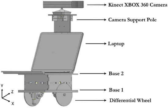
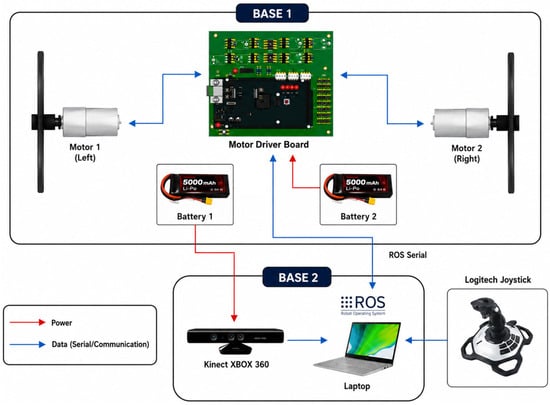
The mobile robot was custom-designed to serve as a stable and effective platform for RGB-D SLAM research. The design focused on functional requirements, component integration, and sensor placement optimization. The key specifications of the platform are summarized in Table 1. The mechanical structure is built upon a two-tiered chassis constructed from acrylic sheets (3 mm and 6 mm thick). This material was selected for its favorable strength-to-weight ratio, ease of fabrication, and electrical insulation properties. The dual-base design provides a functional separation of subsystems: the lower base (Base 1) houses the locomotion system, including motors and power electronics, while the upper base (Base 2) supports the primary computational unit (a laptop) and the sensor mast.
Table 1.
Robot platform specifications.
A critical design feature is the elevated mounting of the Kinect camera. The sensor is positioned at a height of 560 mm on a support pole at the front of the robot. This strategic placement provides a more top-down perspective, which is crucial for high-quality 3D mapping. It maximizes the sensor’s field of view, reduces occlusions from ground-level objects and the robot’s own chassis, and improves the ability to capture the geometry of taller objects, thereby enhancing the overall completeness of the map [26]. The overall design of the robot is shown in Figure 1.
Figure 1.
Mechanical design of the robot.
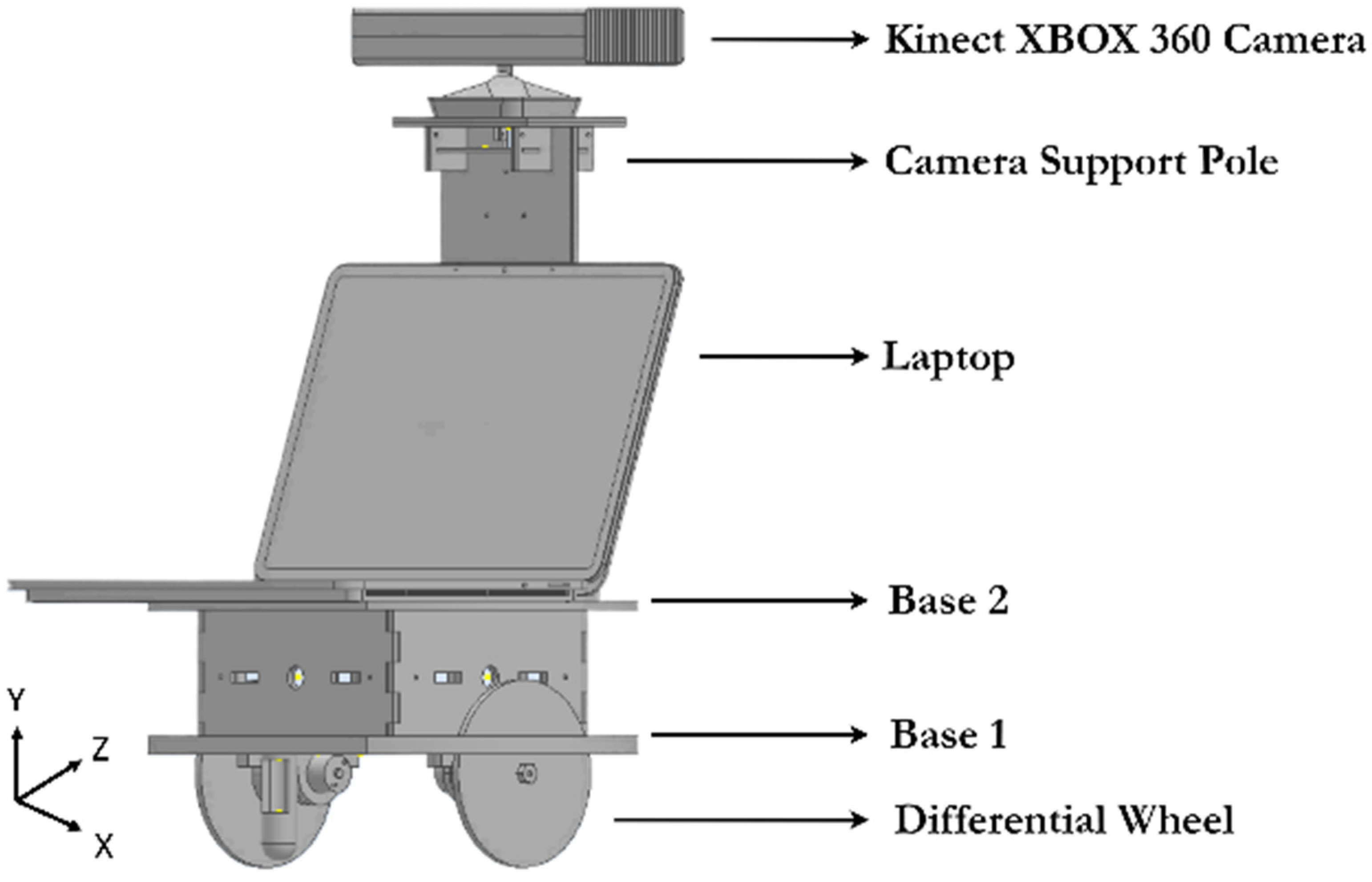
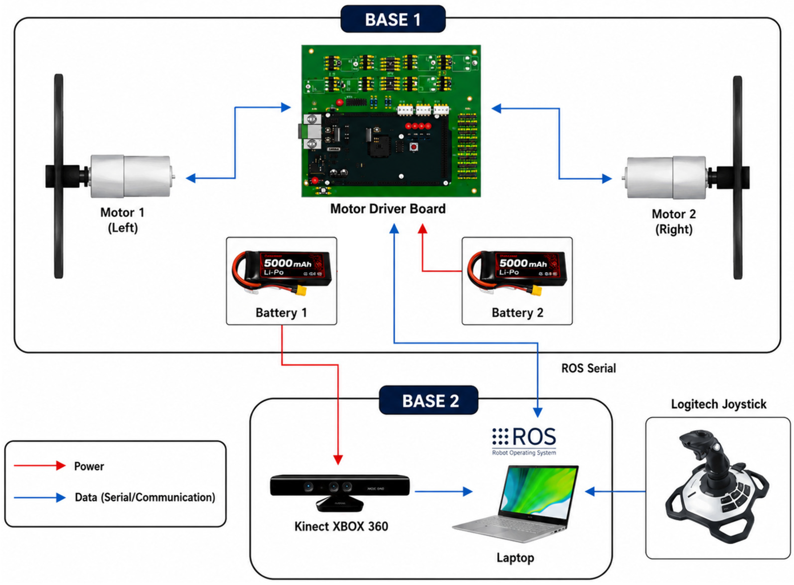
The integrated electronic system is centered around an Arduino Mega microcontroller, which is responsible for low-level motion control. It receives velocity commands and translates them into Pulse-Width Modulation (PWM) signals for the motor drivers. A custom-designed Printed Circuit Board (PCB) integrates the Arduino with MOSFET-based motor drivers and power distribution circuitry, ensuring reliable operation. The complete electronic wiring and data flow diagram is presented in Figure 2.
Figure 2.
Electronic design of a robot.
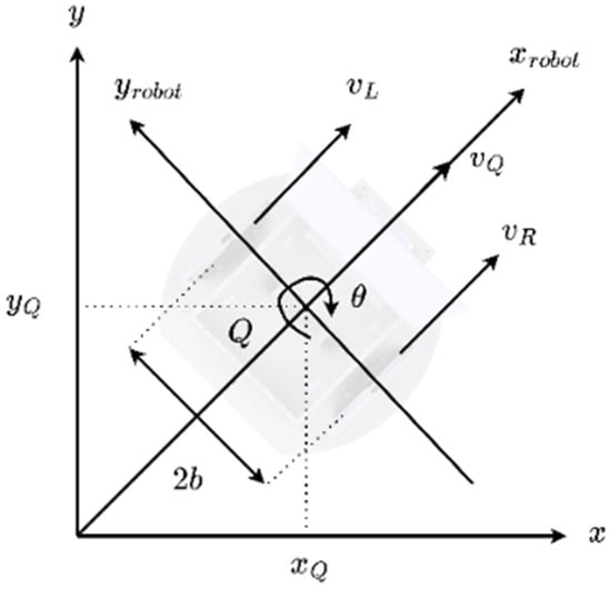
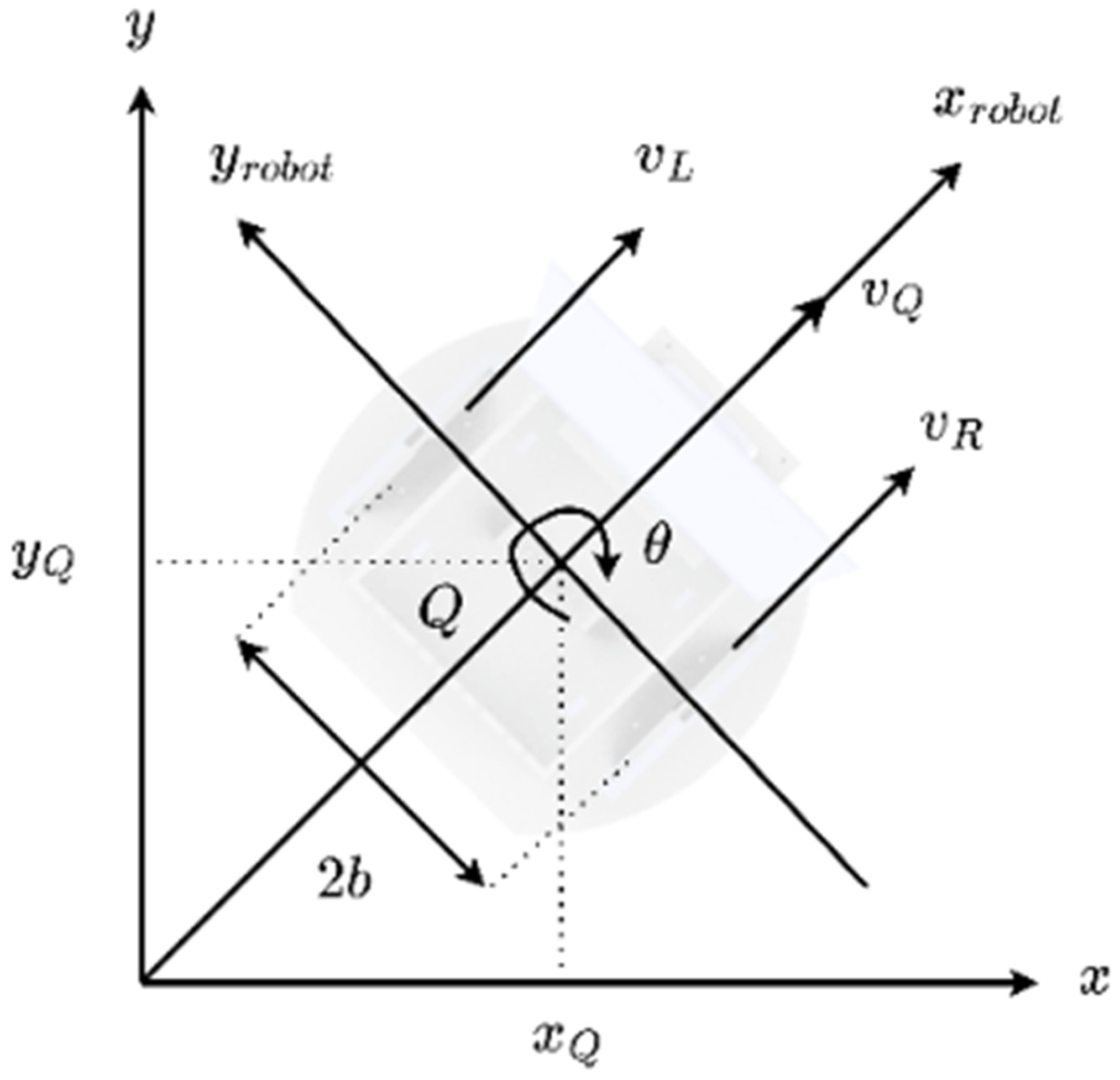
Locomotion is achieved through a differential-drive mechanism, which uses two independently driven wheels for propulsion and steering. The large wheel diameter (230 mm) provides stability and effective traversal over minor surface irregularities [27]. Caster wheels are included for additional support. The kinematic model of the differential drive, which relates the wheel velocities to the robot’s linear and angular velocities, is depicted in Figure 3. Let r denote the wheel radius, ωR(t) and ωL(t) denote the angular velocities of the right and left wheels, respectively, and 2b denote the distance between the two drive wheels, as illustrated in Figure 3. The corresponding linear velocities of the right and left wheels are given as
Figure 3.
Cartesian plane of the differential robot.
The linear velocity of the robot at its instantaneous center point is obtained from the average of the two wheel velocities,
whereas the angular velocity of the robot is determined by the difference between the right- and left-wheel velocities,
Equation (4) indicates that the robot rotates when the two drive wheels operate at different linear velocities, while equal wheel velocities result in zero angular velocity. The forward velocity of the robot can also be related to its translational motion in the global Cartesian frame as
where x(t) and y(t) denote the robot position in the global frame and θ(t) represents its heading angle.
2.2. RGB-D SLAM Framework
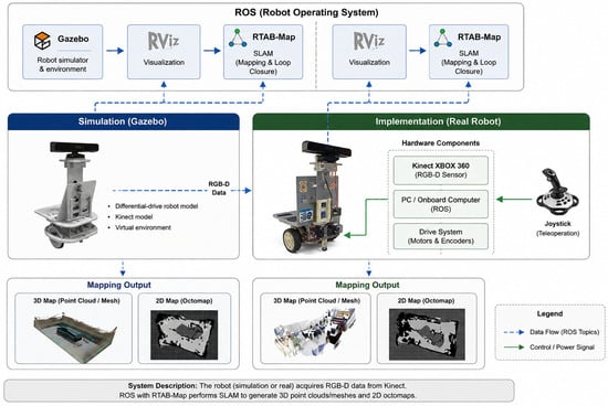
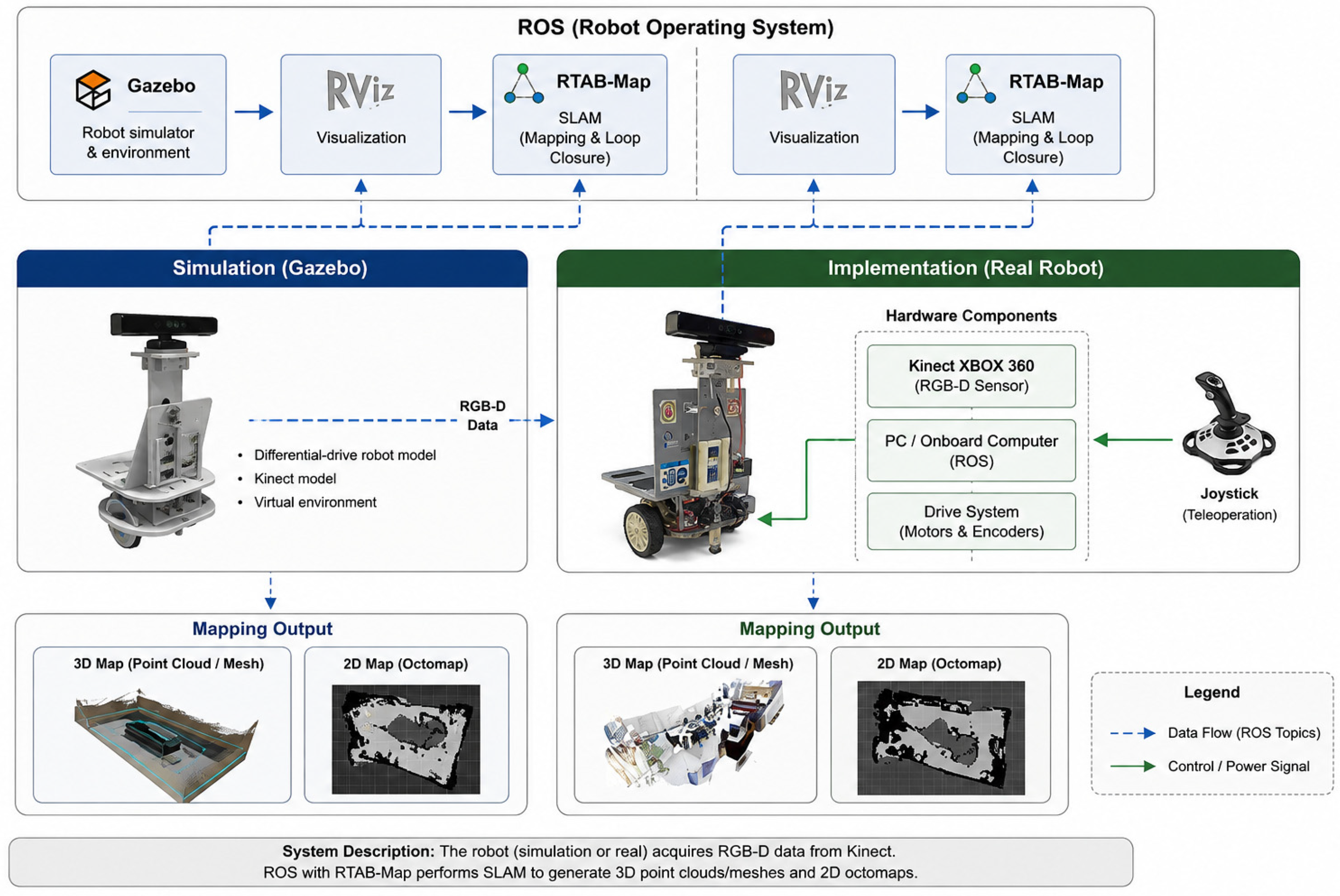
To develop the mapping process, this study integrates the RGB-D SLAM algorithm with the ROS robotic framework. The mapping process consists of two stages: simulation and implementation. Figure 4 provides a systematic description of the design flow of the mapping system, illustrating the tools and outputs for each stage.
Figure 4.
RGB-D SLAM system.
The mapping system is built upon ROS Noetic running on an Ubuntu 20.04 operating system. The ROS serves as the central middleware, providing a structured communication architecture that facilitates data flow between the sensor, the control system, and the SLAM algorithm [28]. The core of the mapping process is the RTAB-Map (Real-Time Appearance-Based Mapping) package, a graph-based SLAM approach optimized for RGB-D sensors [29].
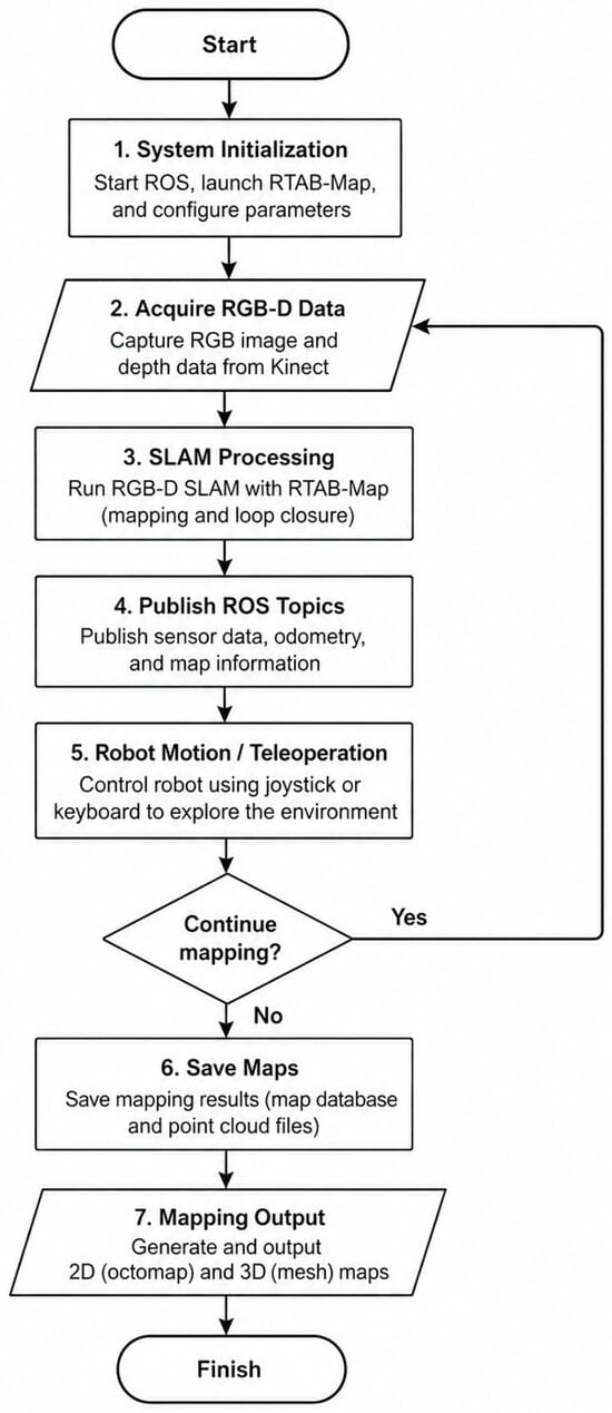
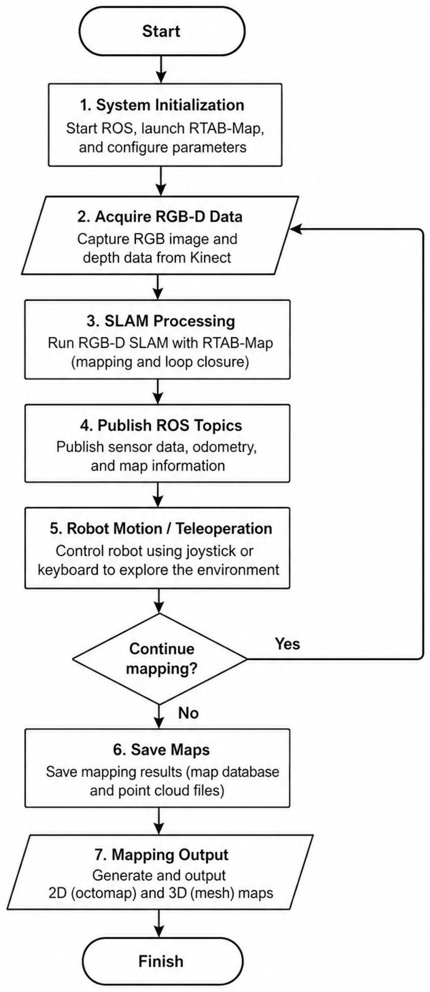
RGB-D SLAM design involves numerous steps. The system is initialized by checking the camera’s status, taking pictures, and using ROS commands. The robot uses the XBOX 360 camera to take images and measure distances. The SLAM algorithm then processes this data. The mapping process is depicted in a flowchart, as seen in Figure 5. This process generates two primary types of environmental representations that are visualized using the ROS tool RViz. The first is a 3D Mesh Map, which is a high-fidelity geometric representation of the environment constructed by aggregating point-cloud data, providing a detailed visualization of object shapes and surfaces. The second, intended for navigation, is a 2D Occupancy Grid (octomap), which is generated by projecting the 3D data. The system uses an octomap where each cell holds a probability value indicating its state: occupied (black), free (white/gray), or unknown (transparent).
Figure 5.
Flowchart of RGB-D SLAM system design.
2.3. Experimental Setup
A two-phase experimental protocol was designed to systematically evaluate the performance of the RGB-D SLAM system, corresponding to the two stages outlined in Figure 4. The initial phase was a simulation conducted in a virtual environment to establish a performance baseline and understand the system’s operational mechanisms under ideal conditions. Using the Gazebo 3D robot simulator, a virtual map of the “student room” at the UGM (Universitas Gadjah Mada) laboratory, with dimensions of 10 m × 15 m, was created. This stage aimed to verify the functionality of the ROS communication pipeline, the RTAB-Map algorithm, and the visualization tools. The robot’s 3D model was loaded into the Gazebo world, and its mapping process was visualized in RViz, which displayed the point-cloud data captured by the virtual camera. The robot was manually navigated throughout the entire virtual space using the teleop ROS package, which translates keyboard inputs into velocity commands.
Following the successful simulation, the second phase involved deploying the physical robot for real-world implementation in and around the laboratory at UGM. For this stage, the robot was manually operated using a Logitech joystick connected to the onboard laptop. Joystick inputs were processed by a ROS node and transmitted via ROS serial to the Arduino microcontroller, which in turn generated PWM signals to control the motors. The system’s performance and robustness were evaluated under four distinct environmental conditions: a tidy indoor room to serve as a baseline, a cluttered indoor room to test performance with multiple static occlusions, an indoor room with a dynamic person walking through to assess resilience to non-static elements, and an outdoor courtyard to challenge the system with variable ambient lighting and less uniform surfaces [30]. To thoroughly analyze the algorithm’s refinement capabilities, a consistent data collection method was used for each scenario: two complete mapping runs were conducted. The first run established an initial map, while the second was performed to evaluate the system’s ability to improve map consistency and accuracy by filling occluded regions and correcting for drift through loop closure detection.
3. Results and Discussion
3.1. Simulation Performance in an Idealized Environment
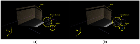
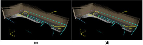
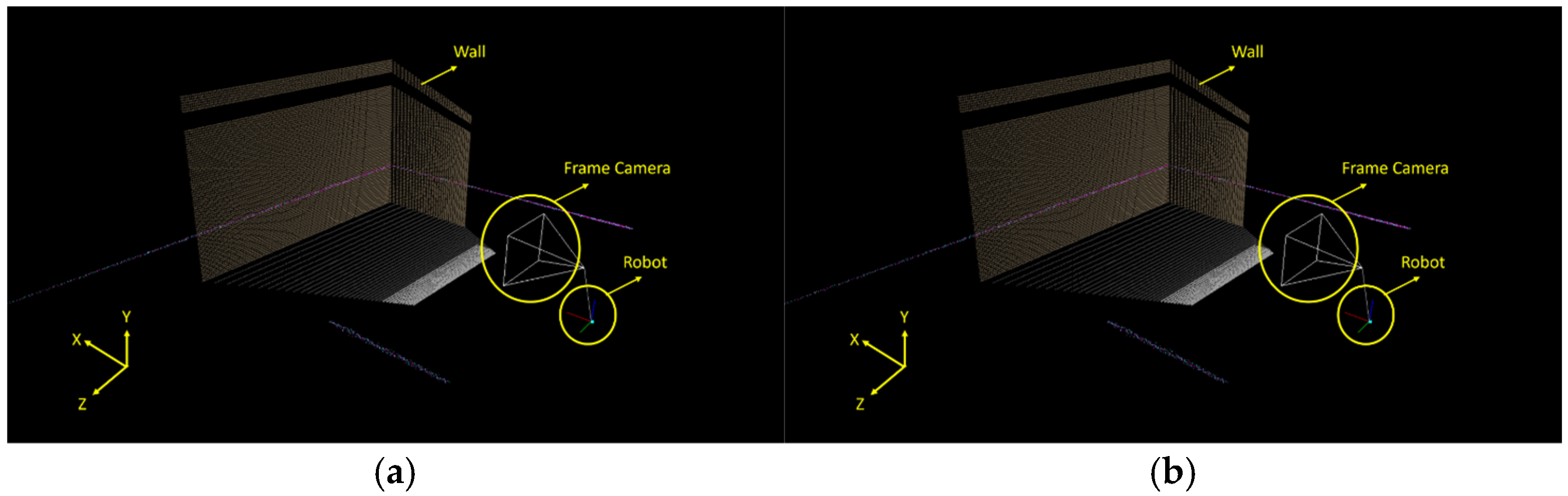
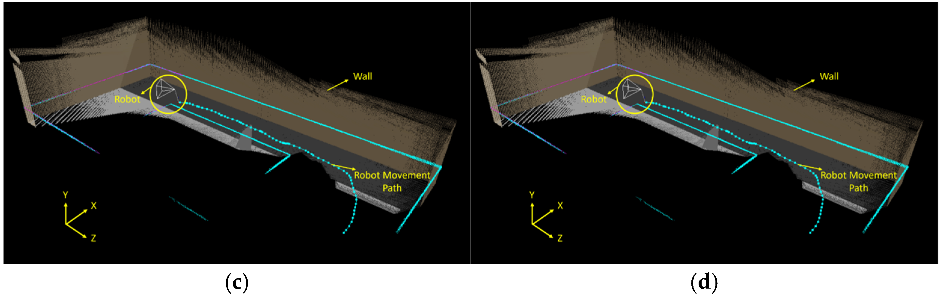
The Gazebo simulation was first conducted to verify the basic operation of the RGB-D SLAM system in a controlled environment. The simulated laboratory had dimensions of 10 m × 15 m, and the system successfully generated a 3-D representation of the environment during robot motion. Figure 6 shows the progressive development of the 3-D map, starting from the initial observation and continuing through partial mapping until the complete room was reconstructed.
Figure 6.
Sequential visualization of the 3D mapping process within the Gazebo simulation: (a) initial room image, (b) room mapping process, (c) half-room mapped, and (d) entire room mapped.
The simulation also indicates that complete mapping depends on the robot trajectory because the RGB-D sensor observes only a limited field of view. Therefore, the robot needs to move through an appropriate path to expose the relevant surfaces to the sensor. This consideration becomes more important in real-world experiments, where obstacles, object occlusion, and sensor-range limitations can further affect the mapping process.
3.2. Quantitative Analysis of RGB-D SLAM Configurations and Mapping Performance
To complement the visual assessment of the generated maps, quantitative analyses were performed on the computational configuration, point-cloud parameters, and sensing characteristics of the RGB-D SLAM system. These analyses provide objective measurements of the system configuration and operating conditions used in the subsequent mapping experiments. First, the computational performance of RTAB-Map was evaluated by varying the queue size and maximum odometry rate. Nine parameter combinations were tested, and the mean memory-update and data-compression times were recorded, as summarized in Table 2.
Table 2.
Computational performance of different RTAB-Map configurations.
The results show that the processing times varied with both parameters. The lowest mean memory-update time was 53.4 s, obtained with a queue size of 50 and a maximum odometry rate of zero, while the lowest mean data-compression time was 10.1 s, obtained with a queue size of 5 or 50 at a maximum odometry rate of zero. The configuration of queue size = 20 and maximum odometry rate = 10 was selected for the subsequent mapping experiments. Under this configuration, the mean memory-update and data-compression times were 56.9 s and 10.6 s, respectively. The selection was based on the overall experimental evaluation of the tested configurations rather than on the minimum value of a single processing metric.
The point-cloud reconstruction parameters were then evaluated by varying the maximum depth and voxel size. Three maximum-depth values (2, 5, and 10 m) and three voxel sizes (0.001, 0.01, and 0.1 m) were tested. The main results are summarized in Table 3.
Table 3.
Point-cloud configuration evaluation.
Based on the experimental comparison, a maximum depth of 10 m and a voxel size of 0.001 m were selected for the subsequent 3-D mapping experiments. The selected voxel size provided a denser point-cloud representation, while the maximum-depth setting allowed a larger portion of the observed scene to be reconstructed.
The sensing characteristics of the Kinect were also evaluated by varying the distance between the sensor and the observed environment. The robot was tested at distances from 1 to 8 m, while an additional rotational test was performed with the target located at approximately 1.5 m. The resulting characteristics are summarized in Table 4.
Table 4.
Quantitative characteristics of the Kinect sensing range.
The results indicate that the practical mapping range of the Kinect was approximately 1–3 m, whereas distances below 1 m represented a blind region. In the rotational test, the point-cloud representation remained relatively clear during the second and third scans at approximately 1.5 m, while further repeated rotations resulted in increasingly blurred observations. These measurements provide an objective characterization of the sensing conditions under which the RGB-D SLAM system was evaluated.
3.3. Real-World Mapping Performance Across Diverse Conditions
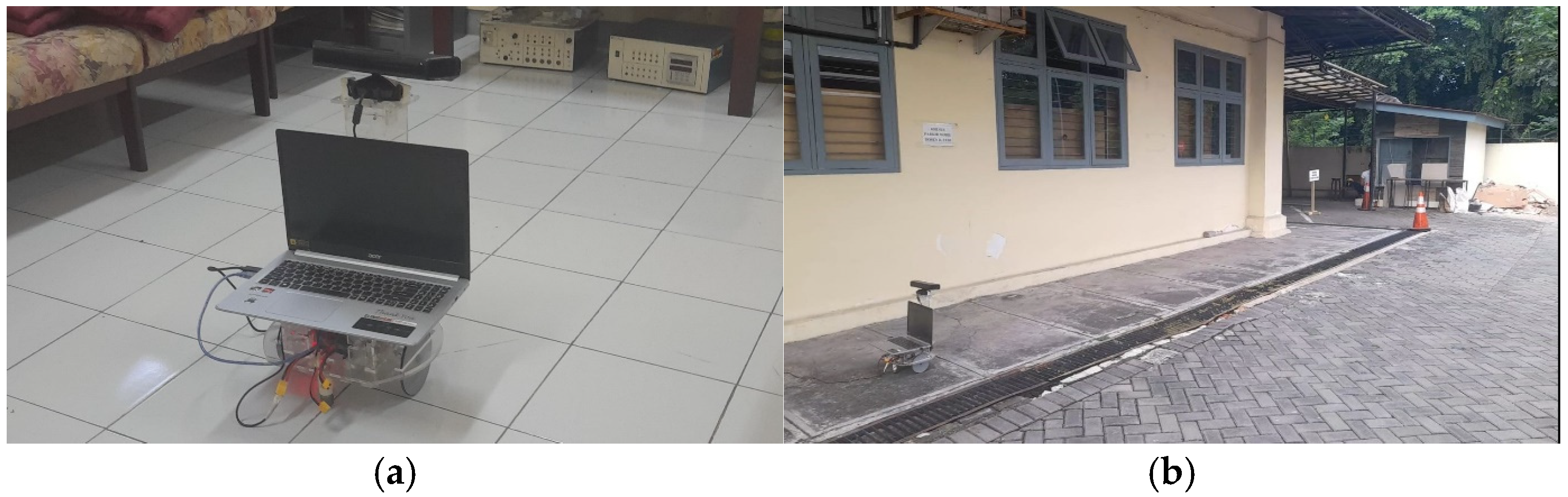
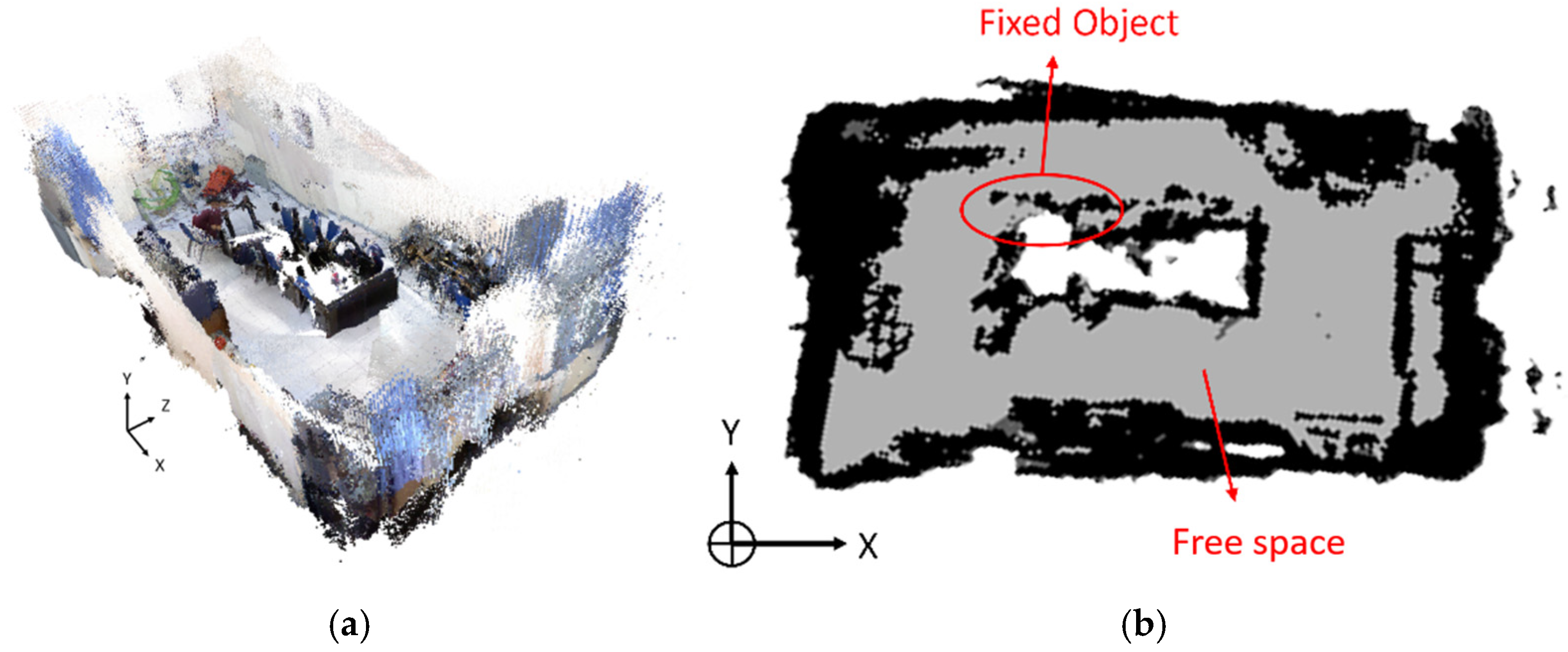
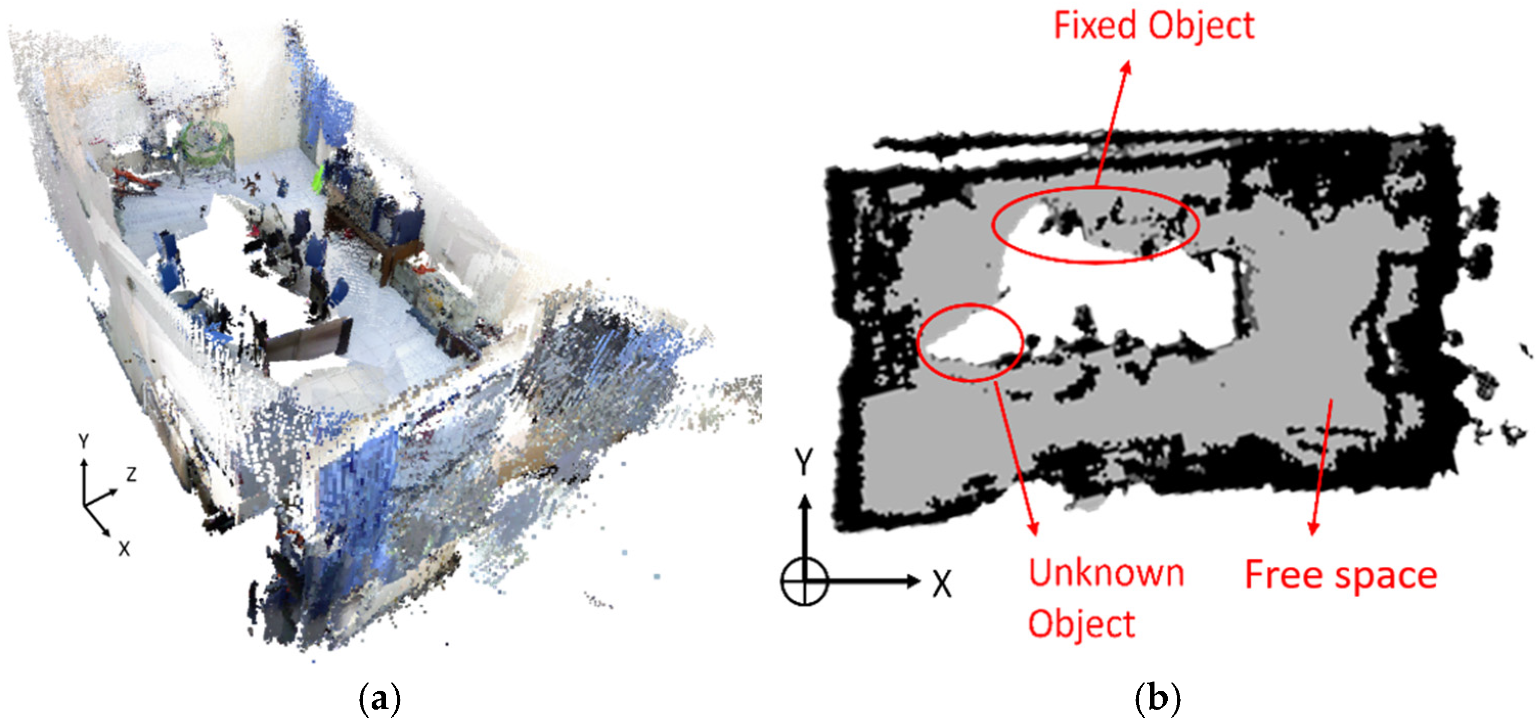
The real-world experiments were conducted in both indoor and outdoor environments to evaluate the mapping performance of the RGB-D SLAM system under different environmental conditions. The experimental setup is shown in Figure 7. Four conditions were considered: tidy indoor, cluttered indoor, indoor with moving objects, and outdoor environments. The tidy indoor condition provided a relatively unobstructed scene, whereas the cluttered indoor condition introduced static objects that caused partial occlusion. The dynamic indoor condition included a moving person, while the outdoor condition represented a more open environment with fewer nearby structural features. The experiments were conducted under the naturally occurring illumination conditions at each test location, which were not quantitatively measured. Each scenario was tested twice using the same mapping procedure. The first run established the initial map, while the second run provided additional observations from the environment to examine the consistency and completeness of the resulting maps. The mapping results presented in Figure 8, Figure 9, Figure 10 and Figure 11 correspond to the second run for each scenario, as indicated in the respective figure captions.
Figure 7.
Real-world robot testing environments: (a) indoor and (b) outdoor.
Figure 8.
Mapping results in the tidy indoor environment (second run): (a) 3-D mesh and (b) 2-D octomap.
Figure 9.
Mapping results in the cluttered indoor environment (second run): (a) 3-D mesh and (b) 2-D octomap.
Figure 10.
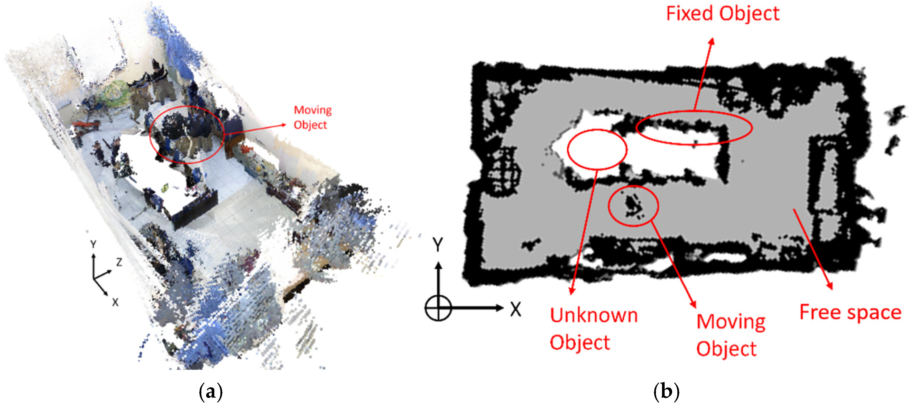
Mapping results in the indoor environment with moving objects (second run): (a) 3-D mesh and (b) 2-D octomap.
Figure 11.
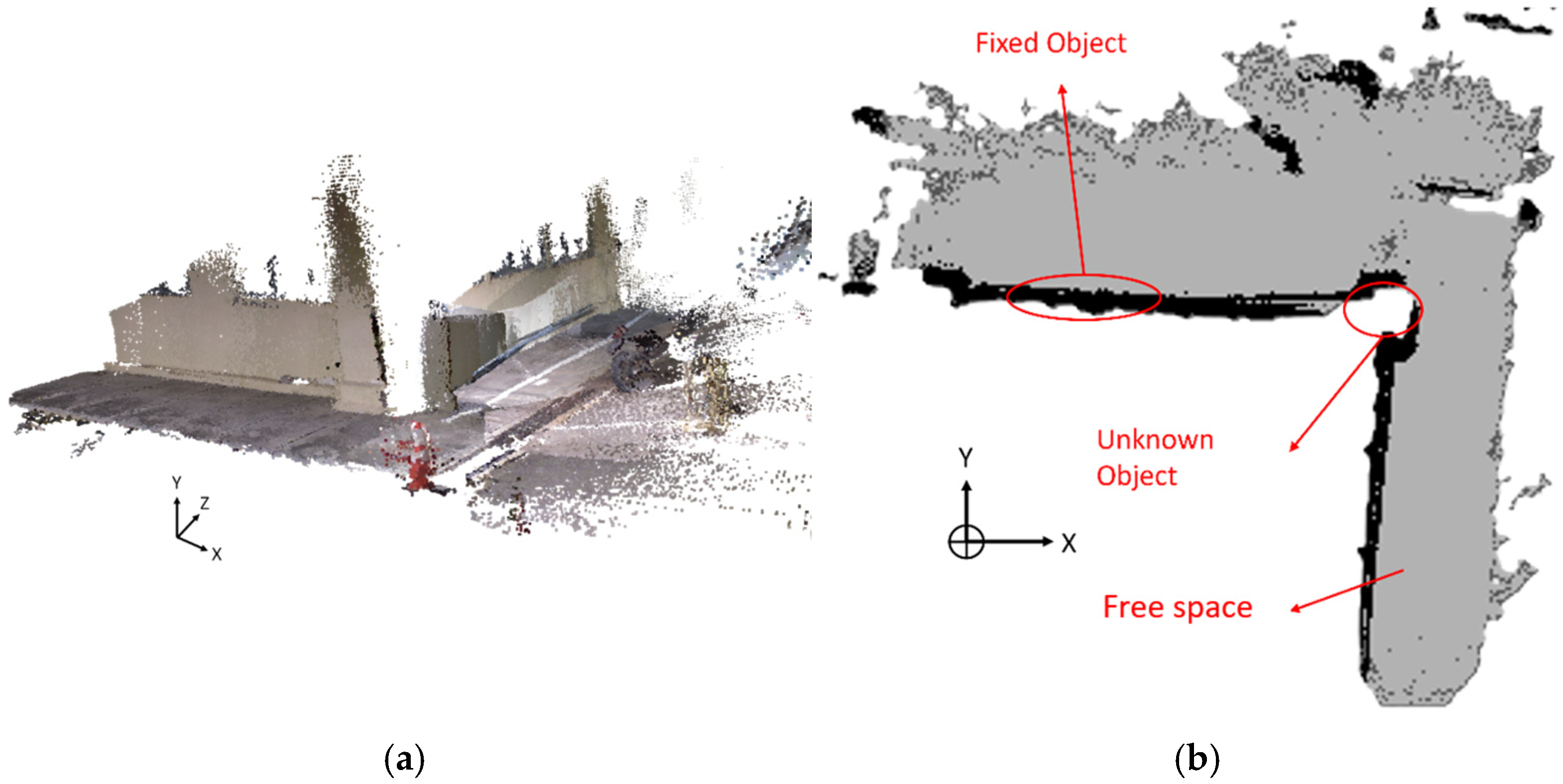
Mapping results in the outdoor environment (second run): (a) 3-D mesh and (b) 2-D octomap.
- (1)
- Indoor Tidy Environment
The tidy indoor environment represents a relatively unobstructed condition with clearly visible walls and surrounding structures. The resulting 3-D mesh and 2-D octomap from the second mapping run are shown in Figure 8. The 3-D mesh provides a spatial representation of the room, while the 2-D octomap clearly represents the main boundaries and occupied regions. Only limited unidentified regions can be observed in the map. The results demonstrate that the RGB-D SLAM system was able to reconstruct the main structures of the indoor environment under relatively favorable conditions. The result also provides a reference for assessing the effects of additional clutter and dynamic objects in the subsequent experiments.
In the 2-D occupancy maps, black regions represent occupied space, gray regions represent free or traversable space, and white regions represent unknown or unobserved areas. The annotations “Fixed Object,” “Moving Object,” and “Unknown Object” indicate stationary structures, transient objects, and regions that could not be sufficiently observed or classified, respectively. Numerical occupancy probabilities were not recorded in the original experiments and are therefore not reported.
- (2)
- Indoor Cluttered Environment
The cluttered indoor environment introduced additional objects that partially obstructed the sensor’s view. As shown in Figure 9, the second mapping run produced a more complete representation of the environment, particularly in regions that were previously affected by occlusion. The presence of an unknown region in the 2-D octomap also illustrates that some parts of the environment remained unobserved.
The difference between the mapping runs indicates the benefit of obtaining observations from different viewpoints. When the robot revisited previously mapped areas, additional surfaces that were not visible during the first pass could be observed and incorporated into the map. This result is consistent with the experimentally determined sensing characteristics in Section 3.2, where the effective Kinect mapping range was approximately 1–3 m. Thus, objects that obstruct the sensor or surfaces located outside the effective sensing range can result in incomplete map regions.
- (3)
- Indoor Environment with Moving Objects
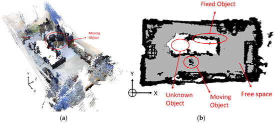
The dynamic indoor experiment was conducted to examine the effect of moving objects on the generated map. Figure 10 shows the resulting 3-D mesh and 2-D octomap from the second mapping run. The moving object is visible in both representations, while an additional unknown region is present in the 2-D map. Compared with the tidy and cluttered environments, the dynamic environment introduces temporal changes that cannot be represented as purely static structures. The presence of the moving object in the resulting map indicates that observations of transient objects can be incorporated into the reconstructed environment when they remain within the sensor’s field of view during mapping. Therefore, the experiment demonstrates both the capability of the system to continue mapping in the presence of motion and a limitation associated with dynamic objects: transient structures may appear as artifacts in the resulting map.
- (4)
- Outdoor Environment
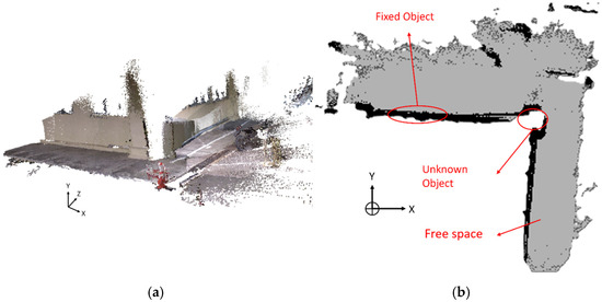
The outdoor experiment evaluated the system under a less structured environment with open space and outdoor objects. The resulting 3-D mesh and 2-D octomap are shown in Figure 11. The system successfully reconstructed the main building boundaries, the road region, and several surrounding structures. However, some regions remained unidentified, as indicated by the unknown object region in the 2-D octomap.
The outdoor result should be interpreted together with the Kinect sensing characteristics reported in Section 3.2. The experimentally determined effective mapping range of approximately 1–3 m limits the amount of environmental information that can be captured when relevant structures are located farther from the robot. In addition, outdoor scenes contain fewer nearby structural features than the indoor environments, which can make continuous spatial reconstruction more challenging. Nevertheless, the generated 3-D and 2-D maps demonstrate that the proposed RGB-D SLAM implementation can operate in the tested outdoor environment.
Overall, the real-world experiments demonstrate that the RGB-D SLAM system was able to generate 2-D and 3-D maps under tidy, cluttered, dynamic, and outdoor conditions. The results also show that mapping completeness depends on environmental occlusion, object motion, and the practical sensing range of the RGB-D sensor. Rather than providing a single accuracy value, the experiments characterize the behavior of the system across different environmental conditions, while the quantitative configuration and sensing results in Section 3.2 provide objective measurements supporting these observations.
The visualization results also reveal several practical limitations of the implemented system. Mapping may become incomplete when objects occlude the sensor’s view or when structures are located beyond the effective sensing range of approximately 1–3 m. Dynamic objects may also be incorporated into the map when they remain within the sensing area for a sufficient period. In outdoor environments, unobserved regions and reduced map completeness may occur because of the larger and less structured surroundings. These cases represent practical limitations of the current implementation and motivate future improvements using higher-performance RGB-D sensors, semantic segmentation, and sensor fusion.
3.4. Comparison with Related Study
To further position the proposed implementation, its characteristics and quantitative results were compared with representative RGB-D SLAM studies as summarized in Table 5. It should be noted that the reported metrics were obtained using different datasets, trajectories, sensors, and evaluation protocols; therefore, they should not be interpreted as direct performance benchmarks. Instead, the comparison highlights the differences in experimental objectives and evaluation methodologies.
Table 5.
Comparison with related RGB-D SLAM implementations.
Acosta-Amaya et al. [23] investigated RTAB-Map and ORB-SLAM2 on a ROS-compatible mobile robotic platform and demonstrated the capability of RTAB-Map to generate dense three-dimensional maps from RGB-D data. However, the study primarily focused on qualitative mapping performance and did not report trajectory-error metrics. Merzlyakov and Macenski [24] quantitatively evaluated several visual SLAM methods using public benchmark datasets and reported an average ATE RMSE of 0.287 m for RTAB-Map on the TUM RGB-D Pioneer dataset, with an execution duration of 7 min 13 s. Caminal et al. [25] evaluated RTAB-Map using Kinect RGB-D datasets and reported an average ATE RMSE of 0.125 m across the evaluated sequences.
In contrast, the present study focuses on the practical implementation of RTAB-Map using a Kinect Xbox 360 mounted on a differential-drive mobile robot. Rather than emphasizing trajectory-accuracy benchmarking, this work investigates mapping performance under simulation and four real-world environmental conditions. In addition, quantitative analyses of RTAB-Map configuration parameters, processing times, point-cloud settings, and Kinect sensing characteristics were conducted to provide objective evidence supporting the mapping results.
Although direct numerical comparison is not possible due to the absence of ground-truth trajectory measurements, the results demonstrate that the proposed low-cost RGB-D SLAM implementation can generate consistent 2-D and 3-D maps while providing quantitative computational and sensor-characterization analyses that are rarely reported in implementation-oriented studies.
4. Conclusions
This study implemented an RGB-D SLAM system on a differential-drive mobile robot using a Microsoft Kinect for Xbox 360 and ROS. Simulation and real-world experiments demonstrated the ability of the system to generate both 2-D octomaps and 3-D meshes in tidy indoor, cluttered indoor, dynamic indoor, and outdoor environments. The quantitative evaluation showed that the selected RTAB-Map configuration (queue size = 20 and odometry maximum rate = 10) resulted in mean memory-update and data-compression times of 56.9 s and 10.6 s, respectively. The Kinect sensor exhibited an effective mapping range of approximately 1–3 m, with a blind region below 1 m. The results indicate that low-cost RGB-D sensing combined with RTAB-Map can provide practical environmental mapping for mobile robotic applications, while mapping completeness remains affected by occlusion, dynamic objects, and sensor-range limitations. Future work will focus on improving robot mobility, evaluating higher-performance RGB-D sensors, and integrating semantic segmentation or sensor-fusion techniques to enhance mapping performance in dynamic environments.
Author Contributions
Conceptualization, F. and H.M.; methodology, P.M.R. and R.A.; software, F., P.M.R., and R.A.; validation, M.J.; formal analysis, P.B.; investigation, F., P.M.R., R.A., and H.M.; resources, F. and H.M.; data curation, P.M.R. and R.A.; writing—original draft preparation, F. and H.M.; writing—review and editing, F., H.M., and M.J.; visualization, F., P.M.R., and R.A.; supervision, M.J. and P.B.; project administration, M.J.; funding acquisition, P.B. All authors have read and agreed to the published version of the manuscript.
Funding
This study was funded by Lodz University of Technology.
Institutional Review Board Statement
Not applicable.
Informed Consent Statement
Not applicable.
Data Availability Statement
The data presented in this study are available on request from the corresponding author. The data are not publicly available due to privacy restrictions.
Acknowledgments
During the preparation of this study, the authors used ChatGPT 5.6 Luna to improve readability and language. After using this tool/service, the authors reviewed and edited the content as needed and took full responsibility for the content of the publication.
Conflicts of Interest
The authors declare no conflicts of interest.
References
- Akmal, M.D.; Al Tahtawi, A.R.; Wijayanto, K.; Wahab, F. Trajectory Tracking Control Design for Mobile Robot Using Interval Type-2 Fuzzy Logic. J. Fuzzy Syst. Control 2024, 2, 67–73. [Google Scholar] [CrossRef] [Scilit]
- Irsyadi, F.; Hendry, J.; Saputro, J.S.; Sasongko, A.B.; Gumay, M.H. Improved Indoor Localization Mechanism for Automated Guided Robots Using Bluetooth Beacons. J. Electr. Electron. Inf. Commun. Technol. 2025, 7, 34–38. [Google Scholar] [CrossRef] [Scilit]
- Licardo, J.T.; Domjan, M.; Orehovački, T. Intelligent Robotics—A Systematic Review of Emerging Technologies and Trends. Electronics 2024, 13, 542. [Google Scholar] [CrossRef] [Scilit]
- Campilho, R.D.S.G.; Silva, F.J.G. Industrial Process Improvement by Automation and Robotics. Machines 2023, 11, 1011. [Google Scholar] [CrossRef] [Scilit]
- Tong, Y.; Liu, H.; Zhang, Z. Advancements in Humanoid Robots: A Comprehensive Review and Future Prospects. IEEE/CAA J. Autom. Sin. 2024, 11, 301–328. [Google Scholar] [CrossRef] [Scilit]
- Nwankwo, L.; Fritze, C.; Bartsch, K.; Rueckert, E. ROMR: A ROS-based open-source mobile robot. HardwareX 2023, 14, e00426. [Google Scholar] [CrossRef] [Scilit] [PubMed]
- Albonico, M.; Đorđević, M.; Hamer, E.; Malavolta, I. Software engineering research on the Robot Operating System: A systematic mapping study. J. Syst. Softw. 2023, 197, 111574. [Google Scholar] [CrossRef] [Scilit]
- Macenski, S.; Moore, T.; Lu, D.V.; Merzlyakov, A.; Ferguson, M. From the desks of ROS maintainers: A survey of modern & capable mobile robotics algorithms in the robot operating system 2. Robot. Auton. Syst. 2023, 168, 104493. [Google Scholar] [CrossRef] [Scilit]
- Gupta, A.; Fernando, X. Simultaneous Localization and Mapping (SLAM) and Data Fusion in Unmanned Aerial Vehicles: Recent Advances and Challenges. Drones 2022, 6, 85. [Google Scholar] [CrossRef] [Scilit]
- Fahmizal, F.; Pratikno, M.S.; Isnianto, H.N.; Mayub, A.; Maghfiroh, H.; Anugrah, P. Control and Navigation of Differential Drive Mobile Robot with PID and Hector SLAM: Simulation and Implementation. J. Ilm. Tek. Elektro Komput. Inform. 2024, 10, 594–607. [Google Scholar] [CrossRef] [Scilit]
- Zhang, J.; Han, F.; Han, D.; Yang, J.; Zhao, W.; Li, H. Integration of Sonar and Visual-Inertial Systems for SLAM in Underwater Environments. IEEE Sens. J. 2024, 24, 16792–16804. [Google Scholar] [CrossRef] [Scilit]
- Yang, L.; Li, P.; Qian, S.; Quan, H.; Miao, J.; Liu, M.; Hu, Y.; Memetimin, E. Path Planning Technique for Mobile Robots: A Review. Machines 2023, 11, 980. [Google Scholar] [CrossRef] [Scilit]
- Al-Tawil, B.; Hempel, T.; Abdelrahman, A.; Al-Hamadi, A. A review of visual SLAM for robotics: Evolution, properties, and future applications. Front. Robot. AI 2024, 11, 1–18. [Google Scholar] [CrossRef] [Scilit] [PubMed]
- Zhao, Y.L.; Hong, Y.T.; Huang, H.P. Comprehensive Performance Evaluation between Visual SLAM and LiDAR SLAM for Mobile Robots: Theories and Experiments. Appl. Sci. 2024, 14, 3945. [Google Scholar] [CrossRef] [Scilit]
- Chen, L.; Li, G.; Xie, W.; Tan, J.; Li, Y.; Pu, J.; Chen, L.; Gan, D.; Shi, W. A Survey of Computer Vision Detection, Visual SLAM Algorithms, and Their Applications in Energy-Efficient Autonomous Systems. Energies 2024, 17, 5177. [Google Scholar] [CrossRef] [Scilit]
- Islam, Q.U.; Ibrahim, H.; Chin, P.K.; Lim, K.; Abdullah, M.Z. MVS-SLAM: Enhanced multiview geometry for improved semantic RGBD SLAM in dynamic environment. J. Field Robot. 2024, 41, 109–130. [Google Scholar] [CrossRef] [Scilit]
- Zhang, J.; Yuan, L.; Ran, T.; Peng, S.; Tao, Q.; Xiao, W.; Cui, J. A dynamic detection and data association method based on probabilistic models for visual SLAM. Displays 2024, 82, 102663. [Google Scholar] [CrossRef] [Scilit]
- Li, J.; Gao, W.; Wu, Y.; Liu, Y.; Shen, Y. High-quality indoor scene 3D reconstruction with RGB-D cameras: A brief review. Comput. Vis. Media 2022, 8, 369–393. [Google Scholar] [CrossRef] [Scilit]
- Tychola, K.A.; Tsimperidis, I.; Papakostas, G.A. On 3D Reconstruction Using RGB-D Cameras. Digital 2022, 2, 401–421. [Google Scholar] [CrossRef] [Scilit]
- Khan, M.S.A.; Hussian, D.; Khan, S.; Rehman, F.U.; Aqeel, A.B.; Khan, U.S. Implementation of SLAM by using a Mobile Agribot in a Simulated Indoor Environment in Gazebo. In Proceedings of the 2021 International Conference on Robotics and Automation in Industry, ICRAI 2021, Rawalpindi, Pakistan, 26–27 October 2021; pp. 1–4. [Google Scholar] [CrossRef] [Scilit]
- Sahili, A.R.; Hassan, S.; Sakhrieh, S.M.; Mounsef, J.; Maalouf, N.; Arain, B.; Taha, T. A Survey of Visual SLAM Methods. IEEE Access 2023, 11, 139643–139677. [Google Scholar] [CrossRef] [Scilit]
- Wijayathunga, L.; Rassau, A.; Chai, D. Challenges and Solutions for Autonomous Ground Robot Scene Understanding and Navigation in Unstructured Outdoor Environments: A Review. Appl. Sci. 2023, 13, 9877. [Google Scholar] [CrossRef] [Scilit]
- Acosta-Amaya, G.A.; Cadavid-Jimenez, J.M.; Jimenez-Builes, J.A. Three-Dimensional Location and Mapping Analysis in Mobile Robotics Based on Visual SLAM Methods. J. Robot. 2023, 2023, 6630038. [Google Scholar] [CrossRef] [Scilit]
- Merzlyakov, A.; MacEnski, S. A Comparison of Modern General-Purpose Visual SLAM Approaches. IEEE Int. Conf. Intell. Robot. Syst. 2021, 2, 9190–9197. [Google Scholar] [CrossRef] [Scilit]
- Caminal, I.; Casas, J.R.; Royo, S. SLAM-based 3D Outdoor Reconstructions from LIDAR Data. In Proceedings of the 2018 International Conference on 3D Immersion (IC3D), Brussels, Belgium, 5–6 December 2018; pp. 1–8. [Google Scholar]
- Mishra, D.K.; Thomas, A.; Kuruvilla, J.; Kalyanasundaram, P.; Prasad, K.R.; Haldorai, A. Design of mobile robot navigation controller using neuro-fuzzy logic system. Comput. Electr. Eng. 2022, 101, 108044. [Google Scholar] [CrossRef] [Scilit]
- Tao, Y.; Gao, C.; Shi, Y.; Li, M.; Zhang, M.; Liu, D. Analysis of Motion Characteristics and Stability of Mobile Robot Based on a Transformable Wheel Mechanism. Appl. Sci. 2022, 12, 12348. [Google Scholar] [CrossRef] [Scilit]
- Zhao, J.; Liu, S.; Li, J. Research and Implementation of Autonomous Navigation for Mobile Robots Based on SLAM Algorithm under ROS. Sensors 2022, 22, 4172. [Google Scholar] [CrossRef] [Scilit] [PubMed]
- Li, L.; Schulze, L.; Kalavadia, K. Promising SLAM Methods for Automated Guided Vehicles and Autonomous Mobile Robots. Procedia Comput. Sci. 2024, 232, 2867–2874. [Google Scholar] [CrossRef] [Scilit]
- Jabłoński, M.; Borkowski, P. Correction Mechanism for Balancing Driving Torques in an Opencast Mining Stacker with an Induction Motor and Converter Drive System. Energies 2022, 15, 1282. [Google Scholar] [CrossRef] [Scilit]

Disclaimer/Publisher’s Note: The statements, opinions and data contained in all publications are solely those of the individual author(s) and contributor(s) and not of MDPI and/or the editor(s). MDPI and/or the editor(s) disclaim responsibility for any injury to people or property resulting from any ideas, methods, instructions or products referred to in the content. |
© 2026 by the authors. Licensee MDPI, Basel, Switzerland. This article is an open access article distributed under the terms and conditions of the Creative Commons Attribution (CC BY) license.