


Abstract
Vanadium redox flow batteries (VRBs) have gained widespread adoption for large-scale energy storage applications, owing to their modular design and long operational lifespan. However, pump faults can severely disrupt electrolyte circulation, resulting in insufficient electrolyte supply, uneven ion concentration distribution, and abnormal electrochemical polarization, which compromise system performance and safety. The operation of VRBs involves the coupling of multiple physical processes, which makes fault analysis particularly challenging. To address this problem, a multiphysics-coupled model is developed using the COMSOL Multiphysics platform based on the conservation laws of momentum, charge, and mass. The model describes the coupled mechanisms among the flow field, concentration field, and electrochemical field. The model is validated through experiments conducted on a small-scale VRB system. Simulation results demonstrate that different pump fault types lead to distinct variations in vanadium ion concentration distribution, potential and overpotential distribution inside the stack, and current density inside the stack. These findings offer predictive insight into the performance degradation associated with pump faults and provide a foundation for the development of accurate fault diagnosis strategies.
1. Introduction
As fossil fuel resources continue to deplete, there is a growing consensus on the necessity of transitioning to renewable, green, and clean energy sources to achieve sustainable socio-economic and environmental development [1,2]. To mitigate the challenges posed by the variability of natural conditions on grid stability, the development of distributed power generation systems and the integration of energy storage technologies have become crucial strategies for facilitating the incorporation of renewable energy into power grids [3,4]. Vanadium redox flow batteries (VRBs) are increasingly deployed in large-scale energy storage systems due to their excellent scalability, long cycle life, and decoupled energy and power design [5,6].
However, the intricate architecture of these systems renders them susceptible to various malfunctions, such as pump failures arising from prolonged operation [7,8]. Without timely fault diagnosis and mitigation, these failures can lead to accelerated performance degradation, safety hazards, and even catastrophic system shutdowns [9]. Therefore, there is an urgent need to develop a robust and physically interpretable model that accurately captures the internal states of the battery system.
Electrochemical models, grounded in the principles of mass, energy, and momentum conservation, offer a comprehensive analysis of the charge–discharge mechanisms in VRBs. By formulating a series of nonlinear partial differential equations, these models accurately depict the operational states of VRBs [10]. Early research primarily focused on the overall performance metrics of VRBs. For instance, Blanc et al. [11] developed the electrochemical model capable of predicting stack voltage, vanadium ion concentration variations, and internal losses under diverse operating conditions. The study introduces an innovative strategy to enhance VRB performance by minimizing the power required for electrolyte circulation. As research evolves, the significance of multiphysics coupling effects became increasingly evident. Ozgoli et al. [12] established a comprehensive chemical model that integrates the interactions among electric fields, flow dynamics, and mechanical stresses. Xiong et al. [13] develop a multiphysics, multi-timescale electro–thermal–flow coupled model to capture the intricate interdependencies within VRB systems. To address the challenges posed by extreme temperatures, Rao et al. [14] propose a physics-based VRB model capable of calculating variations in ohmic, activation, and mass transfer overpotentials across a broad temperature spectrum. Given the complexity inherent in simulating VRB internal electrochemical behaviors, some studies have aimed to simplify modeling approaches. Khaki et al. [15] introduce a streamlined mathematical model to estimate the usable capacity of VRBs, facilitating the assessment of state of charge (SOC) and state of health (SOH). To further advance large-scale applications, elaborating internal energy and mass transfer mechanisms remains crucial. Sun et al. [16] develop a coupled electrochemical–thermal mass transfer model to represent internal reactions and heat transfer processes within VRBs. Zorrilla et al. [17] construct a three-dimensional VRB model, providing an in-depth analysis of how varying proton and vanadium concentrations influence half-cell performance, thereby offering potential solutions to mitigate electrolyte imbalance. In summary, these modeling endeavors have significantly propelled the understanding of VRB systems, playing a pivotal role in their design, analysis, control, and fault diagnosis.
Previous studies have predominantly focused on capturing the internal dynamics of VRBs under normal operating conditions. However, pump faults, one of the most common and detrimental faults in practical VRB systems, have received limited attention regarding their internal electrochemical mechanisms. Compared with previous VRB multiphysics models, the novelty of this work can be summarized as follows:
- Pump-fault boundary conditions are introduced into an established three-dimensional flow–concentration–electrochemical coupled model. Instead of proposing a completely new governing equation system, this work extends the existing multiphysics modeling framework to pump-fault conditions by changing the electrolyte flow-rate boundary condition on the faulty side.
- The internal field redistribution under insufficient electrolyte supply is analyzed in detail. The model reveals the highly non-uniform variations in vanadium-ion concentration, potential, overpotential, and current-density distributions inside the stack, which are difficult to measure directly in experiments.
- The relationship between internal electrochemical variations and external voltage abnormalities is clarified. The results provide a physical explanation for performance degradation under pump-fault conditions and offer a mechanistic basis for future pump-fault detection and safe operation of VRB systems.
Therefore, this study focuses on pump-fault mechanism analysis and internal field evolution rather than the development of a complete fault-diagnosis algorithm. The proposed model is simulated using the COMSOL Multiphysics platform and validated through experiments conducted on a small-scale VRB setup.
2. Experimental
2.1. VRB Reactions
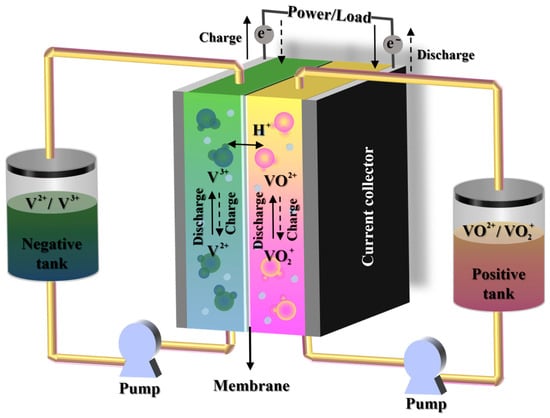
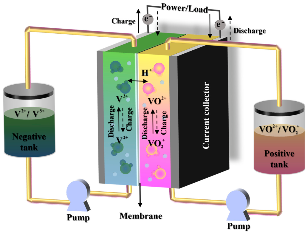
During the operation of a VRB, positive and negative electrolytes are circulated through the respective electrodes within the cell stack by peristaltic pumps. Protons migrate across the proton exchange membrane (PEM), generating internal current and maintaining charge balance within the electrolytes, thereby facilitating the charging–discharging process. The standard electrode potential is approximately +1.004 V for the positive electrode and −0.26 V for the negative electrode, resulting in the standard potential difference of about 1.26 V. The schematic diagram of VRB operation is illustrated in Figure 1. Its geometric parameters are detailed in Table 1.
Figure 1.
Scheme diagram of VRB operation.
Table 1.
VRB geometric parameters.
The positive and negative electrode reaction equations during the charging and discharging processes of the VRB are shown as follows:
During the operation, critical components are susceptible to various failure modes, with pump malfunction being among the most prevalent and detrimental. Such faults usually manifest as abnormal pipeline pressure, electrolyte flow rate, and stack voltage. A pump fault can cause significant electrolyte flow imbalance, leading to inadequate supply on the affected side. Prolonged operation under these conditions may result in localized electrolyte starvation within the cell stack. The positive electrode potential is substantially higher than that of the negative electrode. Insufficient reactant supply can cause non-uniform concentration distribution, local potential gradients, and abnormal electrochemical polarization inside the stack, which may accelerate performance degradation if the fault persists. This scenario poses serious risks to the safe operation of the VRB. Additionally, pump faults can induce abrupt changes in ion concentration within the electrodes, leading to localized currents and elevated potential gradients.
2.2. Assumptions
To streamline computational processes, the multiphysics-coupled pump fault model for VRBs developed is based on the following assumptions:
- The model assumes a static, isothermal environment with a uniform temperature set at 298.15 K, approximating room temperature;
- Side reactions, such as hydrogen and oxygen evolution, are not considered in the model;
- The proton exchange membrane is assumed to be selectively permeable, allowing only protons to pass through;
- The transient charging–discharging processes are simplified to a steady-state conditions;
- The electrolyte is modeled as a diluted solution, enabling the use of the Nernst–Planck equation to describe ion transport phenomena.
These assumptions were adopted to reduce computational complexity and to focus on the primary internal field variations induced by pump faults. The present study mainly investigates the early-stage internal flow, concentration, and electrochemical field distributions after pump faults, rather than the complete transient evolution or long-term degradation process. In the small-scale short-duration experiments conducted in this work, no obvious gas evolution or carbon corrosion was observed. Therefore, side reactions were neglected in the current model.
The steady-state assumption is used to describe the quasi-steady spatial distribution of internal fields after the electrolyte flow rate decreases. Under pump-fault conditions, reducing the flow-rate boundary condition can capture the main spatial non-uniformity of flow velocity, vanadium-ion concentration, potential, overpotential, and current density caused by insufficient electrolyte supply. Similar simplifications have been adopted in previous VRB numerical studies when the main objective was to analyze flow-field distribution, mass transport, and electrochemical behavior rather than long-term degradation. For example, He et al. [18] developed a three-dimensional VRB numerical model to investigate flow-field and electrode optimization while simplifying side reactions. Xiong et al. [19] also used a three-dimensional VRB model to analyze internal flow and electrochemical distributions under different flow-field and electrode deformation conditions. In addition, Puleston et al. [20] reviewed VRB modeling studies and pointed out that side reactions and degradation effects are generally more relevant to long-term performance decay and lifetime estimation. Nevertheless, under severe or prolonged pump-fault conditions, side reactions and transient degradation may become significant and will be considered in future work. It should also be noted that the dilute-solution approximation may not fully capture the non-ideal behavior of concentrated VRB electrolytes, such as activity-coefficient effects and ion–ion interactions. In this work, this assumption is adopted to simplify the ion-transport model and to focus on the primary internal field redistribution caused by pump faults. Therefore, the present model is mainly applicable to short-term pump-fault analysis under the electrolyte concentration used in this study. For higher-concentration electrolytes or long-term operation, non-ideal electrolyte effects should be further considered.
In addition, vanadium crossover through the membrane is not considered in the present model. This simplification is adopted because the present study focuses on short-term pump-fault-induced internal field variations rather than long-term self-discharge or capacity-fading behavior. As reported by Knehr et al. [21], vanadium crossover is an important factor affecting self-discharge and long-term capacity decay in VRBs. However, within the short fault duration considered in this work, the influence of crossover is expected to be limited compared with the dominant effect of electrolyte flow interruption. The effect of vanadium crossover will be further considered in future transient degradation modeling.
2.3. Flow Field Submodel
The VRB pump fault model is grounded in a comprehensive set of partial differential equations, including the conservation of momentum, charge, and mass, as well as electrochemical reaction and reaction kinetics equations. Using COMSOL Multiphysics 6.1, we constructed a multiphysics-coupled model comprising three interrelated submodels: the flow field, concentration field, and electrochemical field. The simulation results provide a theoretical basis for analyzing the internal mechanisms of pump faults.
In the flow field model, the electrolyte velocity is determined by solving the momentum conservation equations. This velocity field directly influences the convective transport term in the concentration field model, establishing a coupling between the two. Furthermore, the diffusion term in the concentration field model is linked to the ionic current density in the electrochemical field model through the effective diffusion coefficient. This interconnection ensures a cohesive representation of the physical phenomena occurring within the VRB under pump fault conditions [22].
The flow field within the VRB under pump fault conditions is modeled using the fluid flow module in COMSOL multiphysics. The model captures the free flow behavior of the electrolyte within both the porous electrodes and the serpentine flow channels by applying the momentum conservation equations. Given the low Reynolds number associated with laminar flow in the porous electrodes, Darcy’s law is employed to describe the fluid motion in these regions. Conversely, the higher Reynolds number in the serpentine flow channels necessitates the use of the incompressible steady-state Navier–Stokes equations to accurately model the electrolyte flow dynamics.
where represents the flow rate of the electrolyte, ρ represents the density of the electrolyte, and P indicates the absolute pressure of the electrolyte.
Darcy’s law applies at the macroscopic scale and the Navier–Stokes equations at the microscopic scale. To ensure continuity of mass at the interface between the porous electrode and the serpentine flow channel in the VRB model, the Brinkman equation is employed as an interface coupling approach. This method effectively bridges the macroscopic Darcy’s law, applicable to porous media, and the microscopic Navier–Stokes equations, suitable for free-flow regions. By incorporating viscous shear effects, the Brinkman equation facilitates a smooth transition between the two flow regimes, ensuring accurate representation of the flow dynamics across the interface.
where u denotes the intrinsic viscosity of the electrolyte, u* represents the effective viscosity within the porous medium. In the Brinkman equation, the viscous term associated with the porous medium can often be neglected due to its relatively minor contribution, allowing for the retention of only the pressure and Darcy terms in the momentum equation [23]. The permeability S of the porous electrode is characterized using the Carman–Kozeny equation, which relates permeability to the structural properties of the porous medium. The equation is expressed as:
where dp is the diameter of the particles comprising the porous medium, SCK represents the fitting constant in the Carman-Kozeny equation, it is set to 5.55 in the paper, and δ represents the porosity of the porous electrode.
2.4. Concentration Field Submodel
The concentration field submodel primarily describes the three mass transfer processes of migration, convection, and diffusion of four vanadium ion species (V2+, V3+, VO2+, VO2+), sulfate ions (SO42−), hydrogen ions (H+), and water molecules within the electrolyte, mainly through the conservation of matter equation. Since the presence of both the electric field and the ion concentration gradient inside a VRB, the transport behavior of each ion can be effectively described by the Nernst–Planck equation, which accounts for diffusion, convection, and electromigration processes.
where the first term on the right-hand side represents electromigration, the second term accounts for convective transport due to the bulk movement of the electrolyte, and the third term describes diffusion resulting from concentration gradients. is the diffusion coefficient of species i, ei is the charge number of species i, F is the Faraday’s constant, R is the universal gas constant, T is the operating temperature, is the gradient of electric field intensity variation, is the fluid velocity vector, ci is the concentration of species i, and is the concentration flux of ionic species i (i = 2, 3, 4, 5). It is refined by Bruggeman’s theory and expressed as:
In accordance with the principle of electroneutrality, the total positive and negative charges within the electrolyte must be balanced. This condition implies that the concentration of one ionic species can be deduced from the concentrations of the others, thereby reducing computational complexity. In this model, the concentration of sulfate ions is calculated based on the concentrations of other charged species present in the system. The electroneutrality condition is mathematically represented as:
2.5. Electrochemical Field Submodel
The electrochemical field model characterizes the conversion mechanisms between electrical and chemical energy during the charging and discharging processes of VRBs. The submodel is grounded in the principles of charge conservation, electrochemical reaction kinetics, and reaction dynamics. The charge conservation equation is expressed as:
where and denote the current density of electrons and ions, respectively, is the electrical conductivity of electrons, and is the electronic and ionic potential, respectively, and is the valence state of species i.
The redox reactions of vanadium ions occurring on the surfaces of porous electrodes during the charging and discharging processes of VRBs are characterized using the Butler–Volmer equation.
where A is the specific surface area of the porous electrode, and are the standard rate constants in (1) and (2), respectively, and are the transfer coefficients of the positive and negative electrodes, respectively, they are set to 0.5 in the paper, and and are the overpotential of the positive and negative electrodes, respectively, as calculated by:
where and are the open-circuit voltage in (1) and (2), respectively. They can be expressed by the Nernst equation as:
where and are the open-circuit voltage in (1) and (2), is the proton concentration, respectively.
2.6. Numerical Details
In the paper, a multiphysics coupled fault model for a VRB is developed using COMSOL Multiphysics®, employing the finite element method (FEM) for numerical simulations. The model parameters are derived from laboratory-scale battery specifications and supplemented with data from relevant literature sources, as detailed in Table 2. The geometric configuration incorporates a serpentine flow field consistent with the experimental setup. The electrolyte flows into the porous electrode from the inlet and undergoes a sufficient redox reaction in the flow channel before exiting through the outlet. A total of 175,000 elements are used in the model to perform the simulations. The relative errors of all the approximate solutions are set to within 10−3. To verify the mesh independence of the numerical results, a mesh sensitivity analysis was performed using three different mesh levels. The coarse, medium, and fine meshes contained approximately 92,000, 175,000, and 268,000 elements, respectively. The terminal voltage, maximum vanadium-ion concentration, and peak overpotential were selected as representative indicators for comparison. The relative differences between the medium and fine meshes were less than 1% for the terminal voltage and less than 3% for the internal-field variables, indicating that further mesh refinement had only a limited influence on the numerical results. Therefore, the medium mesh with approximately 175,000 elements was adopted in this work to balance numerical accuracy and computational cost.
Table 2.
VRB simulation model parameters.
During the simulation, the relative tolerance of the nonlinear solver was set to 10−3. The solution was considered converged when the residuals of the governing equations satisfied the prescribed tolerance and the monitored physical quantities, including terminal voltage and maximum concentration, no longer changed significantly with further iterations.
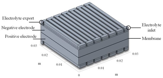
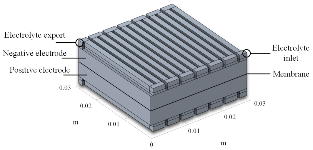
To simulate pump fault conditions, the electrolyte flow rate on the fault side is set to 0.1 mL·min−1, representing a significant deviation from normal operating conditions. The three-dimensional geometry of the multiphysics coupled fault model is illustrated in Figure 2.
Figure 2.
Model geometry appearance.
2.7. Model Validation
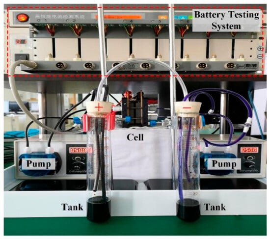
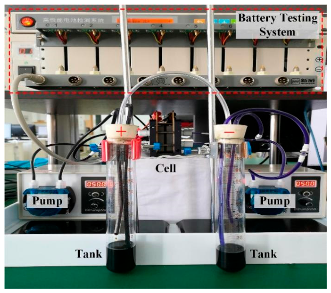
The experimental platform for VRB is established, as depicted in Figure 3. The platform consists of a single-cell system, a high-precision battery test system (BTS-4008T-5V12A) and a host computer. The battery system includes a single cell (LSB-2-FSS), peristaltic pumps (BT100M-YZ1515X), a proton exchange membrane (Nafion 117), 200 mL tanks, 1.7 M vanadium electrolyte, 0.09 m × 0.09 m end plates, serpentine channel, 0.03 m × 0.03 m porous electrodes, and 0.08 m × 0.06 m gaskets. The VRB system is provided by Wuhan Zhisheng New Energy Co., Ltd., Wuhan, China.
Figure 3.
VRB experimental platform.
All experiments are conducted at room temperature 298.15 K (25 °C). The cycling protocol involves charging at a current density of 50 mA/cm2 until reaching a terminal voltage of 1.7 V, followed by discharging at the same current density to a terminal voltage of 0.8 V.
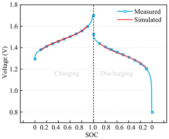
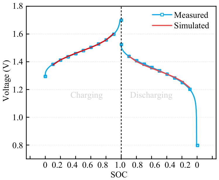
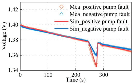
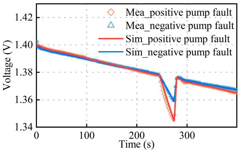
Figure 4 illustrates the comparison between measured and simulated results, which indicates that the proposed model exhibits a high degree of accuracy. During the charging and discharging, the average relative error between the measured and simulated data remains below 1%, demonstrating the model’s effectiveness in capturing the electrochemical behavior of the VRB. To further validate the model under pump-fault conditions, voltage responses under positive and negative pump faults were also compared with experimental measurements. As shown in Figure 5, the simulated voltage agrees well with the measured voltage during both positive and negative pump-fault conditions. The maximum voltage errors are 0.0143 V and 0.0142 V under the positive and negative pump-fault conditions, respectively. These results demonstrate that the proposed model can effectively capture the external voltage response of the VRB under abnormal electrolyte supply. In the experiments, pump faults were produced by controlling the electrolyte flow rate through the peristaltic pumps. Due to the limitations of the present small-scale experimental platform, pressure data were not measured in this work.
Figure 4.
Measured and simulated voltage during charging and discharging.
Figure 5.
Measured and simulated voltage during positive and negative pump faults.
3. Results and Discussion
In the event of a pump fault within a VRB system, a rapid increase in cell voltage is typically observed. This phenomenon is primarily attributed to the significant reduction in electrolyte flow rate, leading to uneven ion concentration distributions within the cell stack. Consequently, the primary redox reactions become concentrated near the electrolyte inlet, resulting in pronounced variations in interfacial potentials and the emergence of localized regions with abnormally high current densities. These localized increases in current density further exacerbate potential gradients between the solid and liquid phases, potentially inducing additional electrochemical stress. Prolonged operation under such fault conditions can precipitate severe degradation of the VRB system, including potential shutdowns and structural damage to the cell stack. Therefore, subsequent study will provide an in-depth analysis of the internal effects of pump failures on the VRB stack, aiming to elucidate the underlying mechanisms.
In this section, the concentration, potential, overpotential, and current-density distributions are selected as the main indicators for interpreting the internal mechanism of pump faults. These variables directly reflect the electrolyte supply state, ion transport behavior, electrochemical polarization, and reaction localization inside the stack. Therefore, the following analysis focuses on the physical meaning of these field variations and their relationship with pump-fault-induced voltage abnormalities.
3.1. Effect of Vanadium Ion Concentration Distribution
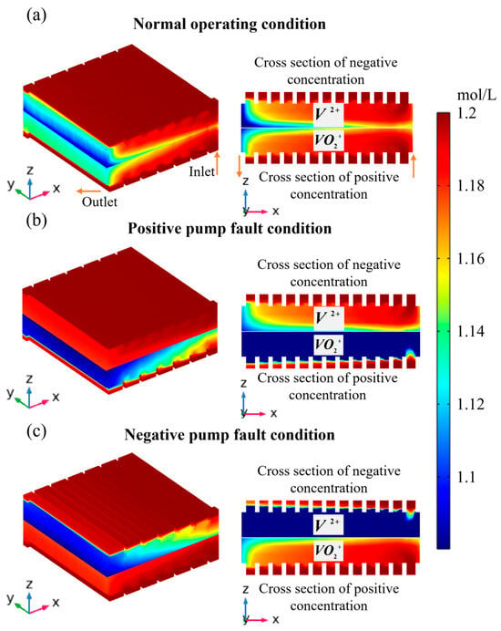
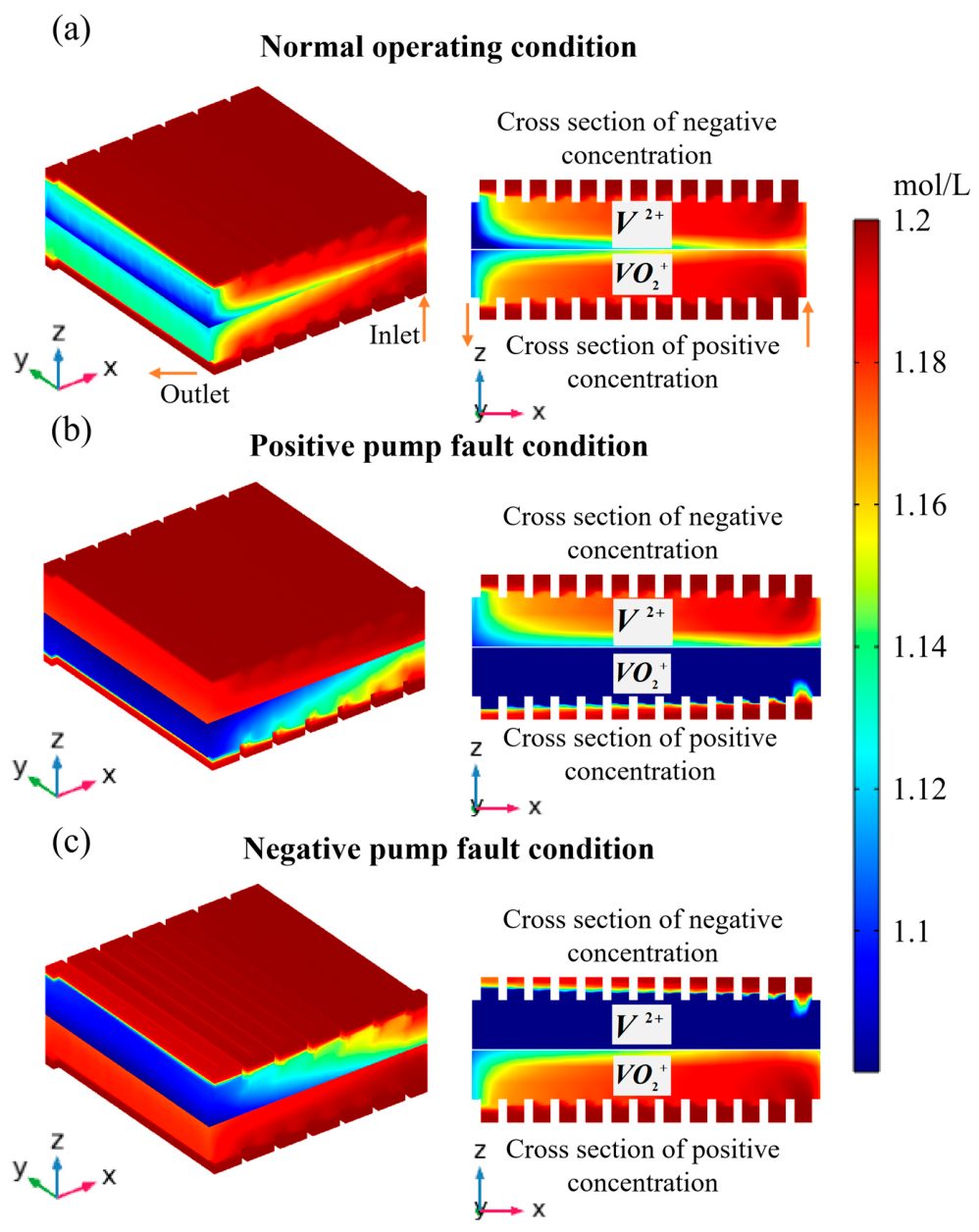
When a pump fault occurs during the operation of the VRB, the electrolyte supply on the affected side becomes insufficient. Despite this, redox reactions continue within the cell stack under the influence of the external current. This leads to the near depletion of certain vanadium ions and results in an uneven distribution of electrolyte concentrations. Taking the discharging as an example, Figure 6 illustrates the concentration distributions of V2+ and VO2+ under three typical conditions: normal operation, positive pump fault, and negative pump fault. Under the normal condition, the electrolyte flows into the stack through the inlet. Here, V2+ is oxidized to V3+, and VO2+ is reduced to VO2+. Due to the progression of reactions along the flow path, higher concentrations of V2+ and VO2+ are observed near the inlet, while lower concentrations are found near the outlet, as depicted in Figure 6a. The reaction proceeds more thoroughly near the outlet, and near the inlet it has not yet had time to react. Thus, there is a gradual increase in the concentration of V2+ and VO2+ from the left (outlet) to the right (inlet) of the cross-section of Figure 6a. In the case of a positive pump fault, the reduction reactions in the positive electrode persist, leading to the complete conversion of VO2+ to VO2+. Subsequently, VO2+ continues to be reduced to V3+, resulting in the near-total depletion of VO2+, with only minimal residual concentrations near the electrolyte inlet. Conversely, during a negative pump fault, the oxidation reactions in the negative electrode proceed, causing the complete transformation of V2+ to V3+. Further oxidation of V3+ to VO2+ ensues, leading to the near-complete exhaustion of V2+, with only trace amounts remaining near the electrolyte inlet.
Figure 6.
Concentration distribution of V2+ and VO2+ under different conditions: (a) normal operation; (b) positive pump fault; (c) negative pump fault.
These scenarios underscore the critical effect of pump fault on the electrolyte composition and distribution within the VRB.
The vanadium-ion concentration distribution is a direct indicator of electrolyte supply and reactant consumption inside the stack. Under pump-fault conditions, insufficient electrolyte flow weakens convective transport and causes a more pronounced concentration gradient in the electrode. Therefore, the local concentration variation shown in Figure 6 reflects the degree of reactant depletion and mass-transfer limitation caused by the pump fault. This concentration non-uniformity provides the basis for the subsequent changes in potential, overpotential, and current-density distribution.
3.2. Effect of Potential Distribution Inside the Stack
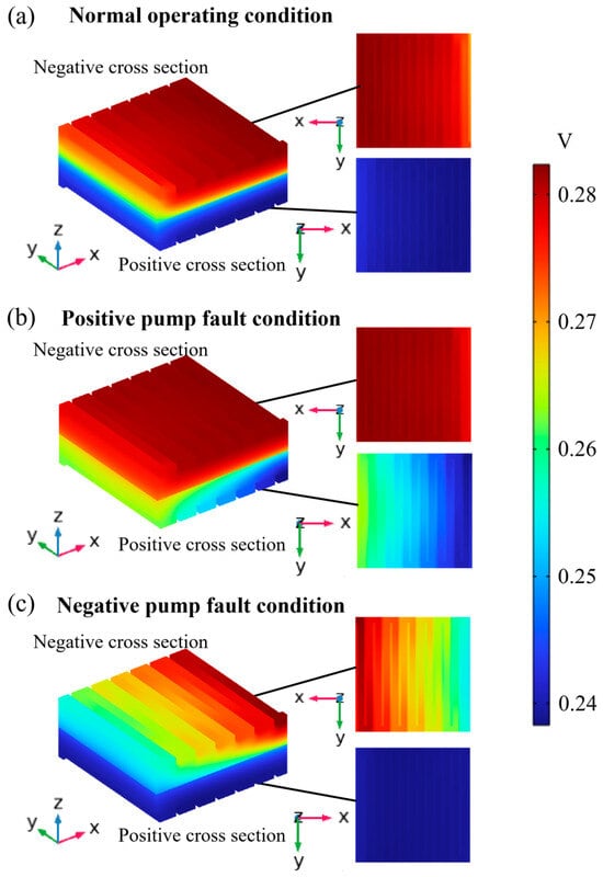
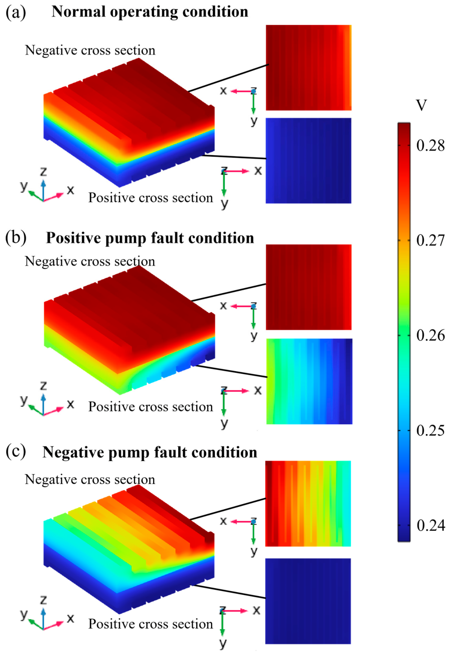
Figure 7 illustrates the potential distribution during discharging under pump fault conditions in a VRB. The imbalance in ion concentrations on the faulty side leads to uneven interfacial potential distribution within the electrolyte. Consequently, the internal reactions within the cell stack become more localized. These reactions predominantly occur near the proton exchange membrane. As a result, significant potential variations are observed in regions adjacent to the membrane at the electrolyte inlet. The potential variation within a single cell range between 0.2 V and 0.5 V. On the side of the electrolyte inlet that is farther from the membrane, reactants are more abundant compared to other regions. During charging, if a positive pump fault occurs, the equilibrium potential of the positive electrode reaction is lower near the membrane. Conversely, in the event of a negative pump fault, the equilibrium potential of the negative electrode reaction is higher near the membrane. Similarly, during discharge, a positive pump fault results in a higher equilibrium potential of the positive electrode reaction near the membrane. In contrast, a negative pump fault leads to a lower equilibrium potential of the negative electrode reaction in the same region.
Figure 7.
Potential distribution under different conditions during the discharging: (a) normal operation; (b) positive pump fault; (c) negative pump fault.
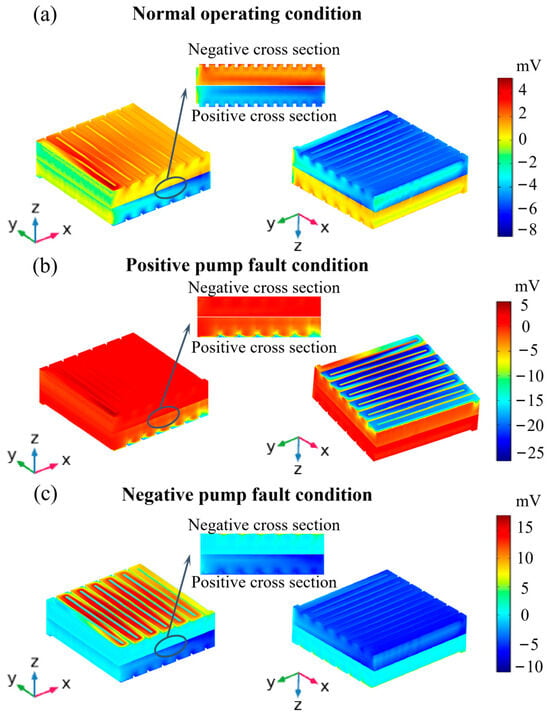
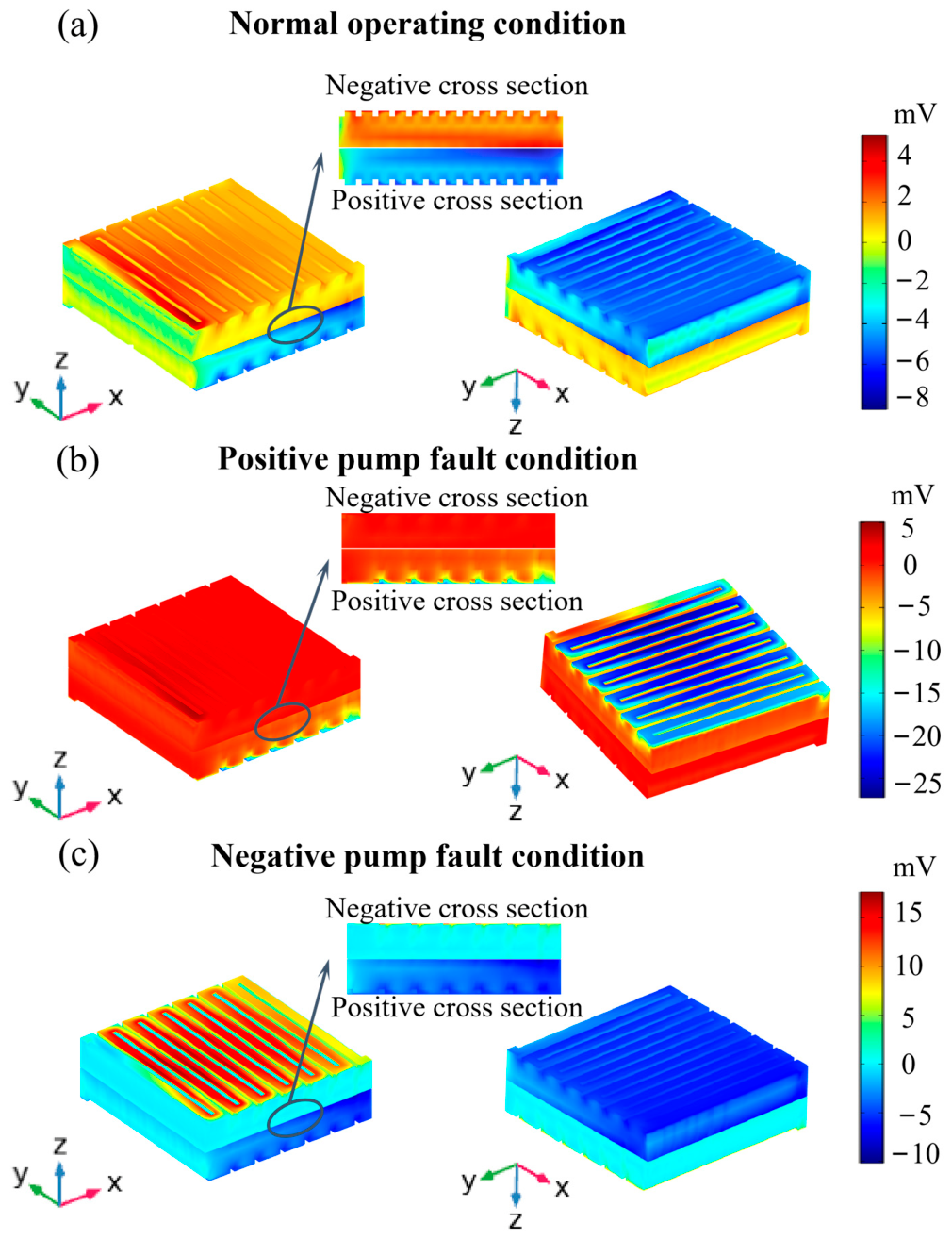
Figure 8 illustrates the overpotential distribution during discharging under pump-fault conditions. Under a positive pump fault, insufficient electrolyte supply on the positive side causes severe local reactant depletion, resulting in enhanced electrochemical polarization near the membrane and electrolyte inlet. Under a negative pump fault, the depletion of V2+ on the negative side also changes the local equilibrium potential and overpotential distribution. These results indicate that pump faults mainly induce localized electrochemical polarization near the main reaction region, rather than a uniform increase in overpotential throughout the whole electrode.
Figure 8.
Overpotential distribution under different conditions during the discharging: (a) normal operation; (b) positive pump fault; (c) negative pump fault.
The potential and overpotential distributions further reveal the electrochemical polarization behavior induced by pump faults. When the electrolyte supply becomes insufficient, the uneven vanadium-ion concentration distribution changes the local equilibrium potential and increases the spatial difference between the solid-phase and liquid-phase potentials. As a result, the overpotential becomes locally enhanced near the main reaction region. Therefore, the overpotential distribution shown in Figure 8 can be regarded as an important indicator for identifying localized electrochemical stress and abnormal reaction behavior inside the stack.
To further evaluate the cell-level influence of pump faults, the global overpotential was calculated by spatially averaging the overpotential over the active electrode region. Although the local overpotential near the electrolyte inlet reaches a relatively high value, the corresponding cell-level overpotential is much smaller. The global overpotential values are 0.6 mV and 2.1 mV under the negative and positive pump-fault conditions, respectively. This result indicates that pump faults mainly cause localized electrochemical polarization near the electrolyte inlet, while their influence on the overall cell voltage is much smaller than the local peak overpotential. Therefore, the local overpotential distribution reflects the internal fault mechanism, whereas the global overpotential provides a more direct link to the measurable cell-level voltage response.
3.3. Effect of Current Density Inside the Stack
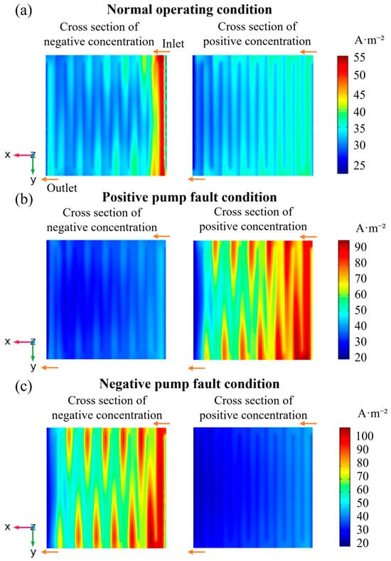
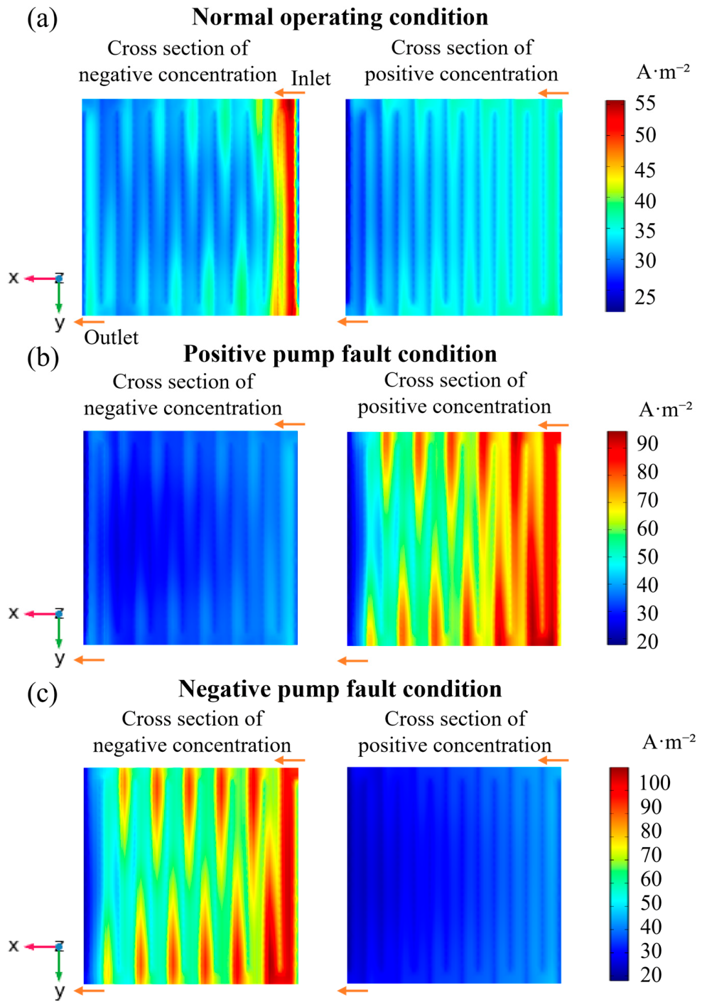
Figure 9 illustrates the current density distribution during discharging under various pump fault conditions in a VRB. The redox reaction current density of vanadium ions within the porous electrodes is influenced by the overpotentials at both the positive and negative electrodes. Under pump fault conditions, reactions tend to concentrate near the electrolyte inlet. This localization leads to abnormal overpotentials, resulting in significantly elevated current densities in regions adjacent to the membrane along the electrolyte flow direction. Conversely, areas farther from the membrane and closer to the electrolyte outlet exhibit relatively stable current densities.
Figure 9.
Current density distribution under different conditions during the discharging: (a) normal operation; (b) positive pump fault; (c) negative pump fault.
The current-density distribution reflects the spatial localization of electrochemical reactions under pump-fault conditions. Due to insufficient electrolyte supply, the redox reaction tends to concentrate in regions where reactants are still available, resulting in a highly non-uniform current-density distribution. This phenomenon indicates that pump faults not only affect the overall voltage response but also change the internal reaction pathway inside the stack. Therefore, the current-density distribution is a key physical indicator for understanding reaction localization and possible performance degradation under pump faults.
These findings emphasize the critical impact of pump faults on the electrochemical behavior in the VRB.
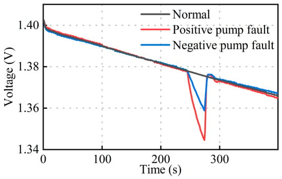
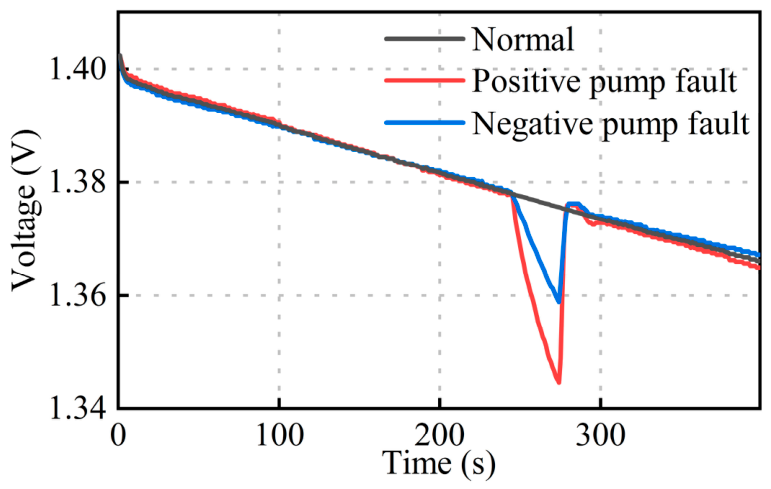
To provide a clearer comparison of the voltage responses under different pump-fault modes, the voltage–time curves under positive and negative pump-fault conditions are shown in Figure 10. It can be observed that both pump-fault modes lead to abnormal voltage variation, but the positive pump fault produces a more pronounced voltage deviation than the negative pump fault. This result indicates that insufficient electrolyte supply on the positive side has a stronger influence on the overall voltage response of the VRB. The voltage–time curves provide a measurable cell-level response that supports the internal field analysis shown in Figure 8 and Figure 9.
Figure 10.
Voltage–time curves under normal, positive and negative pump fault.
4. Conclusions
Reliability of VRB systems is compromised by potential faults in peristaltic pumps, which are critical for maintaining electrolyte circulation. The complex interplay of electrochemical, fluidic, and thermal phenomena in VRBs complicates the analysis and diagnosis of such pump-related faults. To address these challenges, a comprehensive multiphysics model is developed using the COMSOL Multiphysics 6.1. The model is grounded in the fundamental conservation laws of momentum, charge, and mass, enabling the simulation of the coupled behavior of the flow field, concentration field, and electrochemical reactions within the VRB system. The model’s accuracy is validated through experiments conducted on a small-scale VRB platform.
The simulation results show that pump faults mainly affect VRB performance by weakening electrolyte supply and convective mass transport inside the stack. Under pump-fault conditions, the vanadium-ion concentration becomes more unevenly distributed, indicating local reactant depletion and concentration polarization. This concentration redistribution further changes the potential and overpotential distributions, resulting in localized electrochemical polarization near the main reaction region. Meanwhile, the current-density distribution becomes more non-uniform, suggesting that the electrochemical reaction tends to concentrate in limited regions when electrolyte supply is insufficient.
These findings indicate that the external voltage abnormality caused by pump faults is closely related to the internal redistribution of concentration, potential, overpotential, and current density. Therefore, the proposed model provides a physical explanation for pump-fault-induced performance degradation and helps bridge the relationship between measurable external responses and unmeasurable internal electrochemical states.
Although this study does not propose a complete diagnostic algorithm, the obtained results provide a physical basis for pump-fault detection. In practical VRB systems, measurable variables such as stack voltage, electrolyte flow rate, and pipeline pressure can be used as candidate indicators. Therefore, these variables should be continuously monitored during operation to identify abnormal electrolyte circulation in time. Once abnormal voltage variation, flow-rate reduction, or pressure fluctuation is detected, timely inspection of the pump and electrolyte circulation system is recommended to reduce the risk of further performance degradation. Future work will further combine these measurable features with data-driven or model-based methods to establish a complete pump-fault diagnosis framework.
Author Contributions
Conceptualization, L.L. and X.Z.; methodology, S.W.; software, L.L., X.L. and J.J.; validation, H.M., T.W., J.J. and H.L.; formal analysis, C.L.; investigation, L.L.; resources, B.X.; data curation, J.L.; writing—original draft preparation, H.M., L.L., X.Z., T.W. and J.L.; writing—review and editing, S.W., B.X., J.W., X.L., H.L., C.L. and J.J.; visualization, X.L. and J.W.; supervision, H.L.; project administration, B.X. and H.M.; funding acquisition, B.X. and H.M. All authors have read and agreed to the published version of the manuscript.
Funding
This research was funded by the National Natural Science Foundation of China (No. 52177221) and Power China Renewable Energy Co., Ltd. (DJ-PTZX-2024-01).
Institutional Review Board Statement
Not applicable.
Informed Consent Statement
Not applicable.
Data Availability Statement
The raw data supporting the conclusions of this article will be made available by the authors on request.
Conflicts of Interest
Authors Hengshan Mao, Tao Wang, Jun Liu, Jie Wang, Xiaojie Liu, and Haoji Liu were employed by Power China Renewable Energy Co., Ltd. Author Xunzhao Zheng was employed by North China Power Engineering Co., Ltd. of China Power Engineering Consulting Group. The remaining authors declare that the research was con-ducted in the absence of any commercial or financial relationships that could be construed as a potential conflict of interest.
References
- Wei, P.; Abid, M.; Adun, H.; Awoh, D.K.; Cai, D.; Zaini, J.H.; Bamisile, O. Progress in Energy Storage Technologies and Methods for Renewable Energy Systems Application. Appl. Sci. 2023, 13, 5626. [Google Scholar] [CrossRef] [Scilit]
- Chen, J.; Yan, T.; Zhang, Z.; Yang, J.; Zhang, M.; Mao, H.; Fan, H.; Hui, D. Analysis and Evaluation of a Fault-Tolerant Strategy for Module Vanadium Redox-Flow Batteries. J. Energy Eng. 2020, 146, 04020001. [Google Scholar] [CrossRef] [Scilit]
- Clavijo-Camacho, J.; Ruiz-Rodríguez, F.J.; Sánchez-Herrera, R.; Alamo, A.C. Advanced Distribution System Optimization: Utilizing Flexible Power Buses and Network Reconfiguration. Appl. Sci. 2024, 14, 10635. [Google Scholar] [CrossRef] [Scilit]
- Wei, J.; Sun, J.; Zhang, P.; Liu, Y.; Dai, T.; Sun, L.; Tie, Z.; Jin, Z. Energy Density Boosted Vanadium Colloid Flow Batteries Realized by a Reversible Nanoparticle Suspension-Dissolution Strategy. Adv. Funct. Mater. 2024, 34, 2314956. [Google Scholar] [CrossRef] [Scilit]
- Fetyan, A.; Benetho, B.P.; Alkindi, T.; Andisetiawan, A.; Bamgbopa, M.O.; Alhammadi, A.; El-Nagar, G.A. Performance Enhancement of Vanadium Redox Flow Battery with Novel Streamlined Design: Simulation and Experimental Validation. J. Energy Storage 2024, 99, 113397. [Google Scholar] [CrossRef] [Scilit]
- Chen, S.; Sun, C.; Zhang, H.; Yu, H.; Wang, W. Electrochemical Deposition of Bismuth on Graphite Felt Electrodes: Influence on Negative Half-Cell Reactions in Vanadium Redox Flow Batteries. Appl. Sci. 2024, 14, 3316. [Google Scholar] [CrossRef] [Scilit]
- Zou, T.; Shi, X.; Yu, L. Study on Energy Loss of 35 kW All Vanadium Redox Flow Battery Energy Storage System Under Closed-Loop Flow Strategy. J. Power Sources 2021, 490, 229514. [Google Scholar] [CrossRef] [Scilit]
- Guo, Z.; Ren, J.; Sun, J.; Liu, B.; Fan, X.; Zhao, T. A Bifurcate Interdigitated Flow Field with High Performance but Significantly Reduced Pumping Work for Scale-up of Redox Flow Batteries. J. Power Sources 2023, 564, 232757. [Google Scholar] [CrossRef] [Scilit]
- Trovò, A.; Saccardo, A.; Giomo, M.; Guarnieri, M. Thermal Modeling of Industrial-Scale Vanadium Redox Flow Batteries in High-Current Operations. J. Power Sources 2019, 424, 204–214. [Google Scholar] [CrossRef] [Scilit]
- Castro, M.T.; Del Rosario, J.A.D.; Chong, M.N.; Chuang, P.-Y.A.; Lee, J.; Ocon, J.D. Multiphysics Modeling of Lithium-Ion, Lead-Acid, and Vanadium Redox Flow Batteries. J. Energy Storage 2021, 42, 102982. [Google Scholar] [CrossRef] [Scilit]
- Blanc, C.; Rufer, A. Multiphysics and Energetic Modeling of a Vanadium Redox Flow Battery. In Proceedings of the 2008 IEEE International Conference on Sustainable Energy Technologies, Singapore, 24–27 November 2008; pp. 696–701. [Google Scholar]
- Ozgoli, H.A.; Elyasi, S.; Mollazadeh, M. Hydrodynamic and Electrochemical Modeling of Vanadium Redox Flow Battery. Mech. Ind. 2015, 16, 201. [Google Scholar] [CrossRef] [Scilit]
- Xiong, B.; Tang, J.; Li, Y.; Xie, C.; Wang, Z.; Zhang, X.; Beng Gooi, H. Design of A Two-Stage Control Strategy of Vanadium Redox Flow Battery Energy Storage Systems for Grid Application. IEEE Trans. Sustain. Energy 2022, 13, 2079–2091. [Google Scholar] [CrossRef] [Scilit]
- Rao, P.; Jayanti, S. Physics-Based Electrochemical Model of Vanadium Redox Flow Battery for Low-Temperature Applications. Batteries 2023, 9, 374. [Google Scholar] [CrossRef] [Scilit]
- Khaki, B.; Das, P. Voltage Loss and Capacity Fade Reduction in Vanadium Redox Battery by Electrolyte Flow Control. Electrochim. Acta 2022, 405, 139842. [Google Scholar] [CrossRef] [Scilit]
- Sun, K.; Qi, M.; Guo, X.; Wang, W.; Kong, Y.; Chen, L.; Yang, L.; Du, X. Research on Performance Optimization of Novel Sector-Shape All-Vanadium Flow Battery. Sustainability 2023, 15, 14520. [Google Scholar] [CrossRef] [Scilit]
- Zorrilla, F.; Montiel, M.; Mustata, R.; Losantos, R.; Valiño, L. Impact of Electrolyte Composition on the Mitigation of Electrolyte Imbalance in a Vanadium Redox Flow Battery: A 3D Multiphysics Model. J. Energy Storage 2025, 107, 114899. [Google Scholar] [CrossRef] [Scilit]
- He, Q.; Yu, J.; Guo, Z.; Sun, J.; Zhao, S.; Zhao, T.; Ni, M. Modeling of Vanadium Redox Flow Battery and Electrode Optimization with Different Flow Fields. e-Prime-Adv. Electr. Eng. Electron. Energy 2021, 1, 100001. [Google Scholar] [CrossRef] [Scilit]
- Xiong, B.; Li, Y.; Ding, Y.; Wang, J.; Wei, Z.; Zhao, J.; Ai, X.; Fang, J. Numerical Analysis of Vanadium Redox Flow Batteries Considering Electrode Deformation Under Various Flow Fields. J. Power Sources 2023, 564, 232814. [Google Scholar] [CrossRef] [Scilit]
- Puleston, T.; Clemente, A.; Costa-Castelló, R.; Serra, M. Modelling and Estimation of Vanadium Redox Flow Batteries: A Review. Batteries 2022, 8, 121. [Google Scholar] [CrossRef] [Scilit]
- Knehr, K.W.; Agar, E.; Dennison, C.R.; Kalidindi, A.R.; Kumbur, E.C. A Transient Vanadium Flow Battery Model Incorporating Vanadium Crossover and Water Transport Through the Membrane. J. Electrochem. Soc. 2012, 159, A1446–A1459. [Google Scholar] [CrossRef] [Scilit]
- Huang, Z.; Mu, A.; Wu, L.; Wang, H. Vanadium Redox Flow Batteries: Flow Field Design and Flow Rate Optimization. J. Energy Storage 2022, 45, 103526. [Google Scholar] [CrossRef] [Scilit]
- Sun, Z.W.; Duan, Z.N.; Bai, J.Q.; Wang, Y. Numerical Study of the Performance of All Vanadium Redox Flow Battery by Changing the Cell Structure. J. Energy Storage 2020, 29, 101370. [Google Scholar] [CrossRef] [Scilit]

Disclaimer/Publisher’s Note: The statements, opinions and data contained in all publications are solely those of the individual author(s) and contributor(s) and not of MDPI and/or the editor(s). MDPI and/or the editor(s) disclaim responsibility for any injury to people or property resulting from any ideas, methods, instructions or products referred to in the content. |
© 2026 by the authors. Licensee MDPI, Basel, Switzerland. This article is an open access article distributed under the terms and conditions of the Creative Commons Attribution (CC BY) license.